WO2023100508A1 - スイッチング電源装置、スイッチ制御装置、車載機器、及び車両 - Google Patents
スイッチング電源装置、スイッチ制御装置、車載機器、及び車両 Download PDFInfo
- Publication number
- WO2023100508A1 WO2023100508A1 PCT/JP2022/038734 JP2022038734W WO2023100508A1 WO 2023100508 A1 WO2023100508 A1 WO 2023100508A1 JP 2022038734 W JP2022038734 W JP 2022038734W WO 2023100508 A1 WO2023100508 A1 WO 2023100508A1
- Authority
- WO
- WIPO (PCT)
- Prior art keywords
- switch
- state
- power supply
- switching power
- control unit
- Prior art date
- Legal status (The legal status is an assumption and is not a legal conclusion. Google has not performed a legal analysis and makes no representation as to the accuracy of the status listed.)
- Ceased
Links
Images












Classifications
-
- B—PERFORMING OPERATIONS; TRANSPORTING
- B60—VEHICLES IN GENERAL
- B60R—VEHICLES, VEHICLE FITTINGS, OR VEHICLE PARTS, NOT OTHERWISE PROVIDED FOR
- B60R16/00—Electric or fluid circuits specially adapted for vehicles and not otherwise provided for; Arrangement of elements of electric or fluid circuits specially adapted for vehicles and not otherwise provided for
- B60R16/02—Electric or fluid circuits specially adapted for vehicles and not otherwise provided for; Arrangement of elements of electric or fluid circuits specially adapted for vehicles and not otherwise provided for electric constitutive elements
- B60R16/03—Electric or fluid circuits specially adapted for vehicles and not otherwise provided for; Arrangement of elements of electric or fluid circuits specially adapted for vehicles and not otherwise provided for electric constitutive elements for supply of electrical power to vehicle subsystems or for
-
- H—ELECTRICITY
- H02—GENERATION; CONVERSION OR DISTRIBUTION OF ELECTRIC POWER
- H02J—ELECTRIC POWER NETWORKS; CIRCUIT ARRANGEMENTS OR SYSTEMS FOR SUPPLYING OR DISTRIBUTING ELECTRIC POWER; SYSTEMS FOR STORING ELECTRIC ENERGY
- H02J7/00—Circuit arrangements for charging or discharging batteries or for supplying loads from batteries
- H02J7/855—Circuit arrangements for charging or discharging batteries or for supplying loads from batteries with circuits adapted for supplying loads from the battery
-
- H—ELECTRICITY
- H02—GENERATION; CONVERSION OR DISTRIBUTION OF ELECTRIC POWER
- H02M—APPARATUS FOR CONVERSION BETWEEN AC AND AC, BETWEEN AC AND DC, OR BETWEEN DC AND DC, AND FOR USE WITH MAINS OR SIMILAR POWER SUPPLY SYSTEMS; CONVERSION OF DC OR AC INPUT POWER INTO SURGE OUTPUT POWER; CONTROL OR REGULATION THEREOF
- H02M3/00—Conversion of DC power input into DC power output
- H02M3/02—Conversion of DC power input into DC power output without intermediate conversion into AC
- H02M3/04—Conversion of DC power input into DC power output without intermediate conversion into AC by static converters
- H02M3/10—Conversion of DC power input into DC power output without intermediate conversion into AC by static converters using discharge tubes with control electrode or semiconductor devices with control electrode
- H02M3/145—Conversion of DC power input into DC power output without intermediate conversion into AC by static converters using discharge tubes with control electrode or semiconductor devices with control electrode using devices of a triode or transistor type requiring continuous application of a control signal
- H02M3/155—Conversion of DC power input into DC power output without intermediate conversion into AC by static converters using discharge tubes with control electrode or semiconductor devices with control electrode using devices of a triode or transistor type requiring continuous application of a control signal using semiconductor devices only
-
- H—ELECTRICITY
- H02—GENERATION; CONVERSION OR DISTRIBUTION OF ELECTRIC POWER
- H02M—APPARATUS FOR CONVERSION BETWEEN AC AND AC, BETWEEN AC AND DC, OR BETWEEN DC AND DC, AND FOR USE WITH MAINS OR SIMILAR POWER SUPPLY SYSTEMS; CONVERSION OF DC OR AC INPUT POWER INTO SURGE OUTPUT POWER; CONTROL OR REGULATION THEREOF
- H02M3/00—Conversion of DC power input into DC power output
- H02M3/02—Conversion of DC power input into DC power output without intermediate conversion into AC
- H02M3/04—Conversion of DC power input into DC power output without intermediate conversion into AC by static converters
- H02M3/10—Conversion of DC power input into DC power output without intermediate conversion into AC by static converters using discharge tubes with control electrode or semiconductor devices with control electrode
- H02M3/145—Conversion of DC power input into DC power output without intermediate conversion into AC by static converters using discharge tubes with control electrode or semiconductor devices with control electrode using devices of a triode or transistor type requiring continuous application of a control signal
- H02M3/155—Conversion of DC power input into DC power output without intermediate conversion into AC by static converters using discharge tubes with control electrode or semiconductor devices with control electrode using devices of a triode or transistor type requiring continuous application of a control signal using semiconductor devices only
- H02M3/156—Conversion of DC power input into DC power output without intermediate conversion into AC by static converters using discharge tubes with control electrode or semiconductor devices with control electrode using devices of a triode or transistor type requiring continuous application of a control signal using semiconductor devices only with automatic control of output voltage or current, e.g. switching regulators
- H02M3/158—Conversion of DC power input into DC power output without intermediate conversion into AC by static converters using discharge tubes with control electrode or semiconductor devices with control electrode using devices of a triode or transistor type requiring continuous application of a control signal using semiconductor devices only with automatic control of output voltage or current, e.g. switching regulators including plural semiconductor devices as final control devices for a single load
-
- H—ELECTRICITY
- H02—GENERATION; CONVERSION OR DISTRIBUTION OF ELECTRIC POWER
- H02J—ELECTRIC POWER NETWORKS; CIRCUIT ARRANGEMENTS OR SYSTEMS FOR SUPPLYING OR DISTRIBUTING ELECTRIC POWER; SYSTEMS FOR STORING ELECTRIC ENERGY
- H02J2207/00—Details of circuit arrangements for charging or discharging batteries or supplying loads from batteries
- H02J2207/20—Charging or discharging characterised by the power electronics converter
-
- Y—GENERAL TAGGING OF NEW TECHNOLOGICAL DEVELOPMENTS; GENERAL TAGGING OF CROSS-SECTIONAL TECHNOLOGIES SPANNING OVER SEVERAL SECTIONS OF THE IPC; TECHNICAL SUBJECTS COVERED BY FORMER USPC CROSS-REFERENCE ART COLLECTIONS [XRACs] AND DIGESTS
- Y02—TECHNOLOGIES OR APPLICATIONS FOR MITIGATION OR ADAPTATION AGAINST CLIMATE CHANGE
- Y02B—CLIMATE CHANGE MITIGATION TECHNOLOGIES RELATED TO BUILDINGS, e.g. HOUSING, HOUSE APPLIANCES OR RELATED END-USER APPLICATIONS
- Y02B70/00—Technologies for an efficient end-user side electric power management and consumption
- Y02B70/10—Technologies improving the efficiency by using switched-mode power supplies [SMPS], i.e. efficient power electronics conversion e.g. power factor correction or reduction of losses in power supplies or efficient standby modes
Definitions
- the invention disclosed in this specification relates to a switching power supply device that steps down an input voltage to an output voltage, a switch control device, an in-vehicle device, and a vehicle.
- Patent Document 1 As a switching power supply with high efficiency at light load, a switching power supply with a fixed on-time control system is known (see Patent Document 1, for example).
- a switching power supply with a fixed on-time control system is characterized by a variable switching frequency depending on the state of the load.
- the noise frequency also fluctuates, so the effect of noise suppression means (for example, a filter circuit, etc.) for suppressing fixed-frequency noise may decrease. Therefore, it is desirable that the switching frequency of a switching power supply used in an environment where noise becomes a problem is fixed as much as possible.
- the load when the load can be in a state within the normal range and a state lighter than the normal range, not only when the load is within the normal range but also when the load is lighter than the normal range. Even if there is, normal switching control is required.
- a switching power supply device disclosed in this specification is a switching power supply device configured to step down an input voltage to an output voltage.
- the switching power supply includes a first switch having a first end connectable to the input voltage application end and a second end connectable to a first end of an inductor; and a second end of the first switch, the second end being connectable to a low voltage application end lower than the input voltage; a switch and a controller configured to control on/off of the second switch.
- the control unit has a first state in which the first switch is turned on and the second switch is turned off, and a second state in which the first switch is turned off and the second switch is turned on.
- the controller controls a first mode that repeats the first state, the second state, the third state, and the fourth state in a first period, and the first state in a second period that is longer than the first period. and a second mode that repeats the second state, the third state, and the fourth state.
- a switch control device is configured such that a first end is connectable to an input voltage applying end and a second end is connectable to a first end of an inductor. a first switch configured to be connected to a first end of the inductor and a second end of the first switch, and a second end applying a low voltage lower than the input voltage; A switch control device for controlling on/off of a second switch configured to be connectable to an end.
- the switch control device has a first state in which the first switch is turned on and the second switch is turned off, and a second state in which the first switch is turned off and the second switch is turned on.
- the switch control device has a first mode that repeats the first state, the second state, the third state, and the fourth state in a first period, and the second state in a second period that is longer than the first period. and a second mode in which one state, the second state, the third state, and the fourth state are repeated.
- An in-vehicle device includes the switching power supply device configured as described above or the switch control device configured as described above.
- a vehicle includes an on-vehicle device configured as described above, and a battery that supplies electric power to the on-vehicle device.
- normal switching control is easy even when the load is lighter than the normal range, and high efficiency is achieved. can be done.
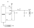
- FIG. 1 is a diagram showing the configuration of a switching power supply device according to the first embodiment.
- FIG. 2 is a timing chart showing the operation of the switching power supply device according to the first embodiment.
- FIG. 3 is a diagram showing the configuration of a switching power supply device according to the second embodiment.
- FIG. 4 is a time chart showing the operation of the switching power supply device according to the second embodiment.
- FIG. 5 is a diagram showing the configuration of a switching power supply device according to the third embodiment.
- FIG. 6 is a timing chart showing the operation of the switching power supply device according to the third embodiment.
- FIG. 7 is a diagram showing the configuration of a switching power supply device according to the fourth embodiment.
- FIG. 8 is a timing chart showing the operation of the switching power supply device according to the fourth embodiment.
- FIG. 1 is a diagram showing the configuration of a switching power supply device according to the first embodiment.
- FIG. 2 is a timing chart showing the operation of the switching power supply device according to the first embodiment.
- FIG. 3 is
- FIG. 9 is a diagram showing a first configuration example of a control unit according to the fifth embodiment.
- 10 is a timing chart showing the operation of the control unit shown in FIG. 9.
- FIG. FIG. 11 is a diagram showing a second configuration example of the control unit according to the fifth embodiment.
- 12 is a timing chart showing the operation of the controller shown in FIG. 11.
- FIG. 13 is a diagram illustrating a third configuration example of a control unit according to the fifth embodiment; 14 is a timing chart showing the operation of the controller shown in FIG. 13.
- FIG. 17 is a diagram illustrating a second configuration example of a control unit according to the sixth embodiment; 18 is a timing chart showing the operation of the control unit shown in FIG. 17;
- FIG. FIG. 19 is a diagram showing a first configuration example of a setting circuit according to the seventh embodiment.
- 20 is a timing chart showing the operation of the setting circuit shown in FIG. 19.
- FIG. 21 is a diagram showing a second configuration example of the setting circuit according to the seventh embodiment. 22 is a timing chart showing the operation of the setting circuit shown in FIG. 21.
- FIG. 23 is a diagram illustrating a first configuration example of a control unit according to the eighth embodiment;
- FIG. 24 is a timing chart showing the operation of the controller shown in FIG. 23.
- FIG. 25 is a diagram illustrating a second configuration example of a control unit according to the eighth embodiment; 26 is a timing chart showing the operation of the controller shown in FIG. 25.
- FIG. FIG. 27 is a diagram illustrating a third configuration example of a control unit according to the eighth embodiment; 28 is a timing chart showing the operation of the control unit shown in FIG. 27;
- FIG. 29 is a diagram illustrating a first configuration example of a control unit according to the ninth embodiment;
- FIG. 30 is a timing chart showing the operation of the controller shown in FIG. 29.
- FIG. FIG. 31 is a diagram showing a second configuration example of the control unit according to the ninth embodiment. 32 is a timing chart showing the operation of the controller shown in FIG. 31.
- FIG. FIG. 33 is a diagram illustrating a third configuration example of a control unit according to the ninth embodiment; 34 is a timing chart showing the operation of the controller shown in FIG. 33.
- FIG. 35 is an external view showing one configuration example of the vehicle.
- a MOS transistor is defined as a gate structure that includes a layer made of a conductor or a semiconductor such as polysilicon with a low resistance value, an insulating layer, and a P-type, N-type, or intrinsic semiconductor.
- layer refers to a transistor consisting of at least three layers. In other words, the structure of the gate of a MOS transistor is not limited to a three-layer structure of metal, oxide, and semiconductor.
- the reference voltage means a voltage that is constant in an ideal state, and is actually a voltage that can slightly fluctuate due to temperature changes and the like.
- a constant voltage means a voltage that is constant in an ideal state, and is actually a voltage that can slightly fluctuate due to temperature changes and the like.
- a constant current means a current that is constant in an ideal state, and is actually a current that can slightly fluctuate due to temperature changes and the like.
- FIG. 1 is a diagram showing the configuration of a switching power supply device according to the first embodiment.
- a switching power supply device 1A (hereinafter referred to as "switching power supply device 1A") according to the first embodiment is a switching power supply device for stepping down an input voltage VIN to an output voltage VOUT. , a second switch SW2, an inductor L1, an output capacitor C1, and an output feedback section FB1.
- the switching power supply device 1A may be configured to operate in a continuous current mode when the load is light, or may be configured to have a reverse current prevention function and operate in a discontinuous current mode when the load is light.
- the control unit CNT1 controls on/off of the first switch SW1 and the second switch SW2 based on the output of the output feedback unit FB1.
- the control unit CNT1 is a switch control device that controls ON/OFF of the first switch SW1 and the second switch SW2.
- the first switch SW1 is configured so that a first end can be connected to the application end of the input voltage VIN, and a second end is configured so that it can be connected to the first end of the inductor L1.
- the first switch SW1 conducts/disconnects a current path from the terminal to which the input voltage VIN is applied to the inductor L1.
- a P-channel MOS transistor, an N-channel MOS transistor, or the like can be used as the first switch SW1.
- the switching power supply 1A may be provided with a bootstrap circuit or the like to generate a voltage higher than the input voltage VIN.
- a first end of the second switch SW2 is configured to be connectable to the first end of the inductor L1 and a second end of the first switch SW1, and a second end is configured to be connectable to the ground potential application end.
- the second switch SW2 conducts/disconnects a current path from the ground potential application end to the inductor L1.
- an N-channel MOS transistor or the like can be used as the second switch SW2.
- a pulse-like switch voltage VSW is generated at the connection node between the first switch SW1 and the second switch SW2.
- the inductor L1 and the output capacitor C1 smooth the pulse-like switch voltage VSW to generate the output voltage VOUT, and supply the output voltage VOUT to the application terminal of the output voltage VOUT.
- a load LD1 is connected to the application terminal of the output voltage VOUT, and the output voltage VOUT is supplied to the load LD1.
- the output feedback unit FB1 generates and outputs a feedback signal according to the output voltage VOUT.
- the output feedback unit FB1 for example, a resistance voltage dividing circuit or the like that divides the output voltage VOUT by resistance to generate a feedback signal can be used. Further, for example, the output feedback unit FB1 may be configured to acquire the output voltage VOUT and output the output voltage VOUT itself as a feedback signal.
- the output feedback unit FB1 is configured to generate and output a feedback signal corresponding to the current flowing through the inductor L1 (hereinafter referred to as "inductor current IL") in addition to the feedback signal corresponding to the output voltage VOUT. good too.
- Current mode control is enabled by the output feedback section FB1 also generating a feedback signal according to the inductor current IL.
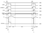
- FIG. 2 is a timing chart showing the operation of the switching power supply 1A.
- the control unit CNT1 sets the length of the first state ST1 according to the feedback signal output from the output feedback unit FB1.
- the control unit CNT1 turns on the first switch SW1 and turns off the second switch SW2.
- the switch voltage VSW becomes a value obtained by adding the forward voltage of the body diode of the first switch SW1 to the input voltage VIN, and then becomes substantially the same value as the input voltage VIN.
- the inductor current IL increases over time.
- control unit CNT1 switches the state of control from the first state ST1 to the second state ST2.
- the control unit CNT1 turns off the first switch SW1 and turns on the second switch SW2.
- the switch voltage VSW becomes substantially the same value as the ground potential GND.
- the inductor current IL decreases over time.
- the control unit CNT1 terminates the second state ST2 and switches the state of control from the second state ST2 to the third state ST3.
- a determination unit (not shown) that determines whether the inductor current IL has decreased to a predetermined value may be provided separately from the control unit CNT1 or may be incorporated in the control unit CNT1. In addition, in this embodiment, the predetermined value is set to zero.
- the control unit CNT1 turns off the first switch SW1 and the second switch SW2.
- the connection node between the first switch SW1 and the second switch SW2 is in a high impedance state, and the switch voltage VSW has substantially the same value as the output voltage VOUT.
- the inductor current IL becomes zero.
- the periodic signal S1 is a signal in which pulses are generated at a fixed period Tfix.
- the periodic signal S1 may be a signal generated inside the control unit CNT1, or a signal generated outside the control unit CNT1 and acquired by the control unit CNT1.
- control unit CNT1 ends the third state ST3 and switches the control state from the third state ST3 to the fourth state ST4.
- the control unit CNT1 turns off the first switch SW1 and turns on the second switch SW2.
- the switch voltage VSW becomes substantially the same value as the ground potential GND.
- the inductor current IL flows from the terminal to which the output voltage VOUT is applied toward the connection node between the first switch SW1 and the second switch SW2, and the amount of current increases over time.
- the inductor current IL is regenerated. The regenerative energy of the inductor current IL is released when switching from the fourth state ST4 to the first state ST1, so that the switch voltage VSW sharply rises when switching from the fourth state ST4 to the first state ST1.
- control unit CNT1 ends the fourth state ST4 and switches the control state from the fourth state ST4 to the first state ST1.
- the control unit CNT1 repeats the first state ST1, the second state ST2, the third state ST3, and the fourth state ST4 at a fixed period Tfix. Between the first state ST1 and the second state ST2, and between the fourth state ST4 and the first state ST1, there is a dead time period in which both the first switch SW1 and the second switch SW2 are turned off. It is desirable to have When a dead time period is provided between the first state ST1 and the second state ST2 and between the fourth state ST4 and the first state ST1, the fixed period Tfix is set to the first state ST1, the first state ST1 and the first state ST1. The dead time provided between the second state ST2, the second state ST2, the third state ST3, the fourth state ST4, and the dead time provided between the fourth state ST4 and the first state ST1 are summed up. Match the period.
- the switching power supply 1A Since the switching power supply 1A operates at the fixed period Tfix and has a configuration in which no loss occurs in the third state ST3, high efficiency can be achieved without varying the switching frequency.
- the length of the first state ST1 is shortened and the length of the third state ST3 is lengthened. Therefore, the switching power supply device 1A greatly improves efficiency when the load LD1 is light. can be made
- the second switch SW2 may be configured so that the second end can be connected to a low voltage application end that is lower than the input voltage VIN and other than the ground potential.
- FIG. 3 is a diagram showing the configuration of a switching power supply device according to the second embodiment.
- a switching power supply device 1B (hereinafter referred to as "switching power supply device 1B") according to the second embodiment has a configuration in which a switch SW3 is added to the switching power supply device 1A.
- the switch SW3 is connected in parallel with the switch SW2. That is, the first end of switch SW3 is connected to the first end of switch SW2, and the second end of switch SW3 is connected to the second end of switch SW2.
- an N-channel MOS transistor or the like can be used as the third switch SW3.
- the control unit CNT1 controls ON/OFF of the third switch SW3 in addition to ON/OFF of the first switch SW1 and the second switch SW2.
- the switch SW3 has at least one of ON resistance (resistance between the first terminal and the second terminal in the ON state) and capacitance (parasitic capacitance between the first terminal and the second terminal) smaller than the switch SW2. .
- FIG. 4 is a timing chart showing the operation of the switching power supply 1B.
- the operation of the switching power supply 1B differs from that of the switching power supply 1A in that the control unit CNT1 turns off the second switch SW2 in the fourth state ST4.
- the controller CNT1 turns on the third switch SW3 instead of the second switch SW2.
- the switching power supply 1B can make the loss in the fourth state ST4 smaller than the switching power supply 1A.
- the control unit CNT1 turns off the third switch SW3.
- the switching power supply 1B operates at the fixed period Tfix and has a configuration in which no loss occurs in the third state ST3, so high efficiency can be achieved without varying the switching frequency.
- the load LD1 is light
- the length of the first state ST1 is short and the length of the third state ST3 is long. Therefore, the switching power supply device 1B greatly improves efficiency when the load LD1 is light. can be made
- control unit CNT1 may turn on both the second switch SW2 and the third switch SW3.
- the second end of the second switch SW2 and the second end of the third switch SW3 are configured to be connectable to a low voltage application end that is lower than the input voltage VIN and other than the ground potential.
- FIG. 5 is a diagram showing the configuration of a switching power supply device according to the third embodiment.
- a switching power supply device 1C (hereinafter referred to as "switching power supply device 1C") according to the third embodiment has a configuration in which a switch SW3, a capacitor C2, and a switch SW4 are added to the switching power supply device 1A.
- a first end of the switch SW3 is connected to a connection node between the first switch SW1 and the second switch SW2.
- a second end of the switch SW3 is connected to a first end of the capacitor C2 and a first end of the fourth switch SW4.
- a second end of the capacitor C2 and a second end of the fourth switch SW4 are connected to the ground potential.
- an N-channel MOS transistor or the like can be used as the third switch SW3.
- an N-channel MOS transistor or the like can be used as the fourth switch SW4.
- the control unit CNT1 controls ON/OFF of the third switch SW3 and the fourth switch SW4 in addition to ON/OFF of the first switch SW1 and the second switch SW2.
- the switch SW3 has at least one of ON resistance (resistance between the first terminal and the second terminal in the ON state) and capacitance (parasitic capacitance between the first terminal and the second terminal) smaller than the switch SW2. . Note that unlike the present embodiment, the switch SW3 may have the same on-resistance and capacity as the switch SW2.
- the switch SW4 is a switch for discharging the capacitor C2. When the switch SW4 is turned on, both ends of the capacitor C2 are short-circuited and the capacitor C2 is discharged.
- FIG. 6 is a timing chart showing the operation of the switching power supply 1C.
- the operation of the switching power supply 1C is basically the same as that of the switching power supply 1B.
- ON/OFF control of the fourth switch SW4 by the controller CNT1 is added.
- the controller CNT1 complementarily controls on/off of the third switch SW3 and on/off of the fourth switch SW4. That is, the control unit CNT1 turns on the fourth switch SW4 in the first state ST1, the second state ST2, and the third state ST3, and turns off the fourth switch SW4 in the fourth state ST4.
- the switch voltage SW exceeds the input voltage VIN by the parasitic capacitance between the first and second terminals of the first switch SW1 and the first terminal of the third switch SW3. and the parasitic capacitance between the second terminal and the capacitance C2.
- the value of the switch voltage SW in the fourth state ST4 can be adjusted by the capacitance value of the capacitor C2. That is, it is possible to adjust how the switch voltage VSW rises when the state is switched from the fourth state ST4 to the first state ST1 by the capacitance value of the capacitor C2.
- control unit CNT1 in the semiconductor integrated circuit device and using the capacitor C2 as an external component of the semiconductor integrated circuit device, it becomes easier to adjust the value of the switch voltage SW in the fourth state ST4.
- the switching power supply 1C operates at the fixed period Tfix and has a configuration in which loss does not occur in the third state ST3, so high efficiency can be achieved without varying the switching frequency.
- the load LD1 is light
- the length of the first state ST1 is short and the length of the third state ST3 is long. Therefore, the switching power supply device 1C greatly improves efficiency when the load LD1 is light. can be made
- the second terminal of the second switch SW2, the second terminal of the capacitor C2, and the second terminal of the fourth switch SW4 are at a low voltage lower than the input voltage VIN and other than the ground potential. It may be configured to be connectable to the application end.
- FIG. 7 is a diagram showing the configuration of a switching power supply device according to the fourth embodiment.
- a switching power supply device 1D (hereinafter referred to as "switching power supply device 1D") according to the fourth embodiment has a configuration in which a capacitor C2 is added to the switching power supply device 1A.
- a first end of the capacitor C2 is connected to a connection node between the first switch SW1 and the second switch SW2.
- the control unit CNT1 controls the voltage VA applied to the second terminal of the switch SW3.
- the control unit CNT1 sets the voltage VA to HIGH level (for example, the same value as the output voltage VOUT) in the third state ST3, and sets the voltage VA to LOW level (for example, the same value as the output voltage VOUT) in the first state ST1, the second state ST2, and the fourth state ST4.
- it is set to the ground potential (GND).
- the switching power supply 1D operates at the fixed cycle Tfix and has a configuration in which no loss occurs in the third state ST3, so high efficiency can be achieved without varying the switching frequency.
- the load LD1 is light
- the length of the first state ST1 is short and the length of the third state ST3 is long. Therefore, the switching power supply device 1D greatly improves efficiency when the load LD1 is light. can be made
- the second end of the second switch SW2 may be configured to be connectable to a low voltage application end that is lower than the input voltage VIN and other than the ground potential.
- Each control unit CNT1 of the switching power supply devices according to the first to fourth embodiments described above shortens the length of the first state ST1 as the load LD1 is lighter. That is, in the switching power supply devices according to the first to fourth embodiments, the lighter the load LD1 is, the narrower the pulse width of the control signal for controlling the switch SW1 becomes, making it difficult to generate the control signal.
- the switching power supply according to the fifth embodiment is a switching power supply that can solve the above problems of the switching power supply according to the first to fourth embodiments.
- the control unit CNT1 changes the first state ST1, the second state ST2, the third state ST3, and the fourth state ST4 at fixed intervals when the load LD1 is in the first range (normal load state). repeat. Therefore, the switching power supply according to the fifth embodiment can fix the switching frequency when the load LD1 is in the first range.
- the control unit CNT1 When the load LD1 is in the second range (light load state), which is lighter than the first range, the control unit CNT1 according to the fifth embodiment lengthens the cycle as the load LD1 is lighter to increase the cycle in the first state ST1. 2 state ST2, 3rd state ST3, and 4th state ST4 are repeated. Therefore, the switching power supply according to the fifth embodiment suppresses narrowing of the pulse width of the control signal for controlling the switch SW1 when the load LD1 is in the second range. In other words, the switching power supply according to the fifth embodiment facilitates normal switching control even when the load LD1 is in a light load state.
- the control unit CNT1 according to the fifth embodiment provides a dead time period DT between the fourth state ST4 and the first state ST1 during which the first switch SW1 and the second switch SW2 are turned off. Then, the control unit CNT1 according to the fifth embodiment determines the length of the dead time period DT and the fourth state ST4 so as to start the first state ST at the zero-crossing point of the inductor current IL when there is no component variation. Set each length to a fixed value. As a result, the switching power supply device according to the fifth embodiment can reduce the loss when the first switch SW1 is turned on, so that the efficiency can be further improved.
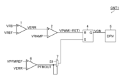
- FIG. 9 is a diagram showing a first configuration example of the control unit CNT1 according to the fifth embodiment.
- FIG. 10 is a timing chart showing the operation of the control unit CNT1 shown in FIG.
- the control unit CNT1 shown in FIG. 9 includes an error amplifier 1, a PWM (Pulse Width Modulation) comparator 2, an AND gate 3, a latch circuit 4, a driver 5, a PFM (Pulse Frequency Modulation) comparator 6, and a selector 7. , a delay circuit 8 , a zero-cross point detection circuit 9 , and a latch circuit 10 .
- an RS flip-flop is used as an example of the latch circuit 4
- a D flip-flop is used as an example of the latch circuit 10.
- the latch circuit 4 will be described as the RS flip-flop 4 and the latch circuit 10 will be described as the D flip-flop 10 .
- the error amplifier 1 outputs an error signal VERR corresponding to the difference between the feedback signal VFB output from the output feedback section FB1 and the reference voltage VREF.
- the PWM comparator 2 outputs a PWM signal VPWM, which is the comparison result between the error signal VERR and the ramp voltage VRAMP.
- the AND gate 3 outputs a reset signal RST, which is the AND of the PWM signal VPWM and the delay signal ONDLY.
- the delay signal ONDLY will be described later.
- the driver 5 controls the first switch SW1 and the second switch SW2 based on the on-time setting voltage VON.
- the PFM comparator 6 outputs a signal VPFMOUT corresponding to the difference between the feedback signal VFB output from the output feedback section FB1 and the reference voltage VPFMREF.
- the signal VPFMOUT pulses when the output voltage VOUT goes below a certain value.
- the selector 7 selects either the periodic signal S1 or the signal VPFMOUT and supplies it to the set terminal (S terminal) of the RS flip-flop 4 .
- the selector 7 selects the periodic signal S1 when the light load mode signal LCMMODE is at low level.
- the selector 7 selects the signal VPFMOUT when the light load mode signal LCMMODE is at high level.
- the light load mode signal LCMMODE will be described later.
- a delay circuit 8 generates a delay signal ONDLY by delaying the on-time setting voltage VON by a first predetermined time.
- a delay circuit 8 generates a delay signal LCMDLY by delaying the on-time setting voltage VON by a second predetermined time. The second predetermined time is longer than the first predetermined time.
- a zero-crossing point detection circuit 9 detects the zero-crossing point of the inductor current IL and outputs a zero-crossing point detection signal ZX.
- the zero-cross point detection signal ZX output from the zero-cross point detection circuit 9 becomes high level when the inductor current IL decreases from positive and reaches the zero-cross point.
- the D flip-flop 10 holds the delayed signal LCMDLY in synchronization with the zero-cross point detection signal ZX, and outputs an inverted signal of the held delayed signal LCMDLY.
- the inverted signal of the delayed signal LCMDLY held by the D flip-flop 10 is the aforementioned light load mode signal LCMMODE.
- the load LD1 is in a light load state when the time from the start of the first state ST1 to the detection of the zero cross point of the inductor current IL is less than a certain value (second predetermined time). I judge.
- the control unit CNT1 shown in FIG. 9 uses the delay signal ONDLY to set the length of the first state ST1 to the minimum time (first predetermined time) when the load LD1 is in the light load state. This prevents the length of the first state ST1 from becoming too short, thereby facilitating normal switching control.
- FIG. 11 is a diagram showing a second configuration example of the control unit according to the fifth embodiment.
- 12 is a timing chart showing the operation of the controller shown in FIG. 11.
- the description of the same parts as in the first configuration example will be omitted as appropriate.
- a control unit CNT1 shown in FIG. 11 includes an error amplifier 1, a PWM comparator 2, an RS flip-flop 4, a driver 5, a PFM comparator 6, and a selector 7.
- the PWM signal VPWM becomes the reset signal RST.
- the selector 7 selects the periodic signal S1 when the signal VPFMOUT is at low level.
- the selector 7 selects the signal VPFMOUT when the signal VPFMOUT is at high level.
- the control unit CNT1 shown in FIG. 11 determines that the load LD1 is in a light load state when the error signal VERR exceeds the reference voltage VPFMREF.
- FIG. 13 is a diagram illustrating a third configuration example of a control unit according to the fifth embodiment; 14 is a timing chart showing the operation of the controller shown in FIG. 13. FIG. Note that, in this configuration example, the description of the same parts as in the second configuration example will be omitted as appropriate.
- the control unit CNT1 shown in FIG. 13 has an AND gate 3 and a delay circuit 8 added to the control unit CNT1 shown in FIG.
- the AND gate 3 and the delay circuit 8 are the same as in the first configuration example except that the delay circuit 8 generates only the delay signal ONDLY.
- the control unit CNT1 shown in FIG. 13 determines that the load LD1 is in a light load state when the error signal VERR exceeds the reference voltage VPFMREF.
- the control unit CNT1 shown in FIG. 13 uses the delay signal ONDLY to set the length of the first state ST1 to the minimum time (first predetermined time) when the load LD1 is in the light load state. This prevents the length of the first state ST1 from becoming too short, thereby facilitating normal switching control.
- the switching power supply device according to the fifth embodiment is a switching power supply device obtained by improving the switching power supply device according to the first embodiment as described above. However, similar improvements can be made to the switching power supply devices according to the second to fourth embodiments. Also, the switching power supply device according to the fifth embodiment can be modified in the same manner as the modifications described in the first to fourth embodiments.
- Each control unit CNT1 of the switching power supply devices according to the first to fifth embodiments described above increases the length of the first state ST1 as the load LD1 becomes heavier. That is, in the switching power supply devices according to the first to fifth embodiments, the heavier the load LD1 is, the thicker the pulse width of the control signal for controlling the switch SW1 becomes, making it difficult to control within the fixed period Tfix. Become.
- the switching power supply according to the sixth embodiment is a switching power supply that can solve the above problems of the switching power supply according to the first to fifth embodiments.
- the switching power supply according to the sixth embodiment is a switching power supply obtained by improving the switching power supply according to the first embodiment. Therefore, in the sixth embodiment, descriptions of the same configurations and operations as in the first embodiment will be omitted.
- the control unit CNT1 repeats the first state ST1, the second state ST2, the third state ST3, and the fourth state ST4 at a fixed cycle based on the periodic signal S1. Therefore, the switching power supply according to the sixth embodiment can fix the switching frequency in synchronization with the periodic signal S1.
- the control unit CNT1 according to the sixth embodiment masks the periodic signal S1 until the zero cross point of the inductor current IL is detected. Therefore, the control unit CNT1 according to the sixth embodiment operates without synchronizing with the periodic signal S1 when the load LD1 is in a heavy load state that is heavier than the normal load state. As a result, the switching power supply according to the sixth embodiment facilitates normal switching control even when the load LD1 is in a heavy load state.
- the control unit CNT1 according to the sixth embodiment provides a dead time period DT between the fourth state ST4 and the first state ST1 during which the first switch SW1 and the second switch SW2 are turned off. Then, the control unit CNT1 according to the sixth embodiment determines the length of the dead time period DT and the fourth state ST4 so as to start the first state ST at the zero-crossing point of the inductor current IL when there is no component variation. Set each length to a fixed value. As a result, the switching power supply device according to the sixth embodiment can reduce the loss when the first switch SW1 is turned on, so that the efficiency can be further improved.
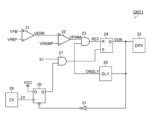
- FIG. 15 is a diagram showing a first configuration example of the control unit CNT1 according to the sixth embodiment.
- 16 is a timing chart showing the operation of the control unit CNT1 shown in FIG. 15.
- FIG. 15 is a diagram showing a first configuration example of the control unit CNT1 according to the sixth embodiment.
- 16 is a timing chart showing the operation of the control unit CNT1 shown in FIG. 15.
- the 15 includes an error amplifier 21, a PWM comparator 22, an AND gate 23, a latch circuit 24, a driver 25, a latch circuit 26, an AND gate 27, a delay circuit 28, and a zero cross check.
- An output circuit 29 , a latch circuit 30 and a NOT gate 31 are provided.
- RS flip-flops are used as an example of the latch circuit 24, and D flip-flops are used as examples of the latch circuits 26 and 30, respectively. Therefore, in the following description, the latch circuit 24 is described as the RS flip-flop 24, the latch circuit 26 is described as the D flip-flop 26, and the latch circuit 30 is described as the D flip-flop 30.
- the error amplifier 21 outputs an error signal VERR corresponding to the difference between the feedback signal VFB output from the output feedback section FB1 and the reference voltage VREF.
- the PWM comparator 22 outputs a PWM signal VPWM, which is the comparison result between the error signal VERR and the ramp voltage VRAMP.
- the AND gate 23 outputs a reset signal RST that is the logical product of the PWM signal VPWM and the delay signal ONDLY.
- the delay signal ONDLY will be described later.
- the RS flip-flop 24 delays the signal supplied to the set terminal (S terminal) inside the RS flip-flop 4 to generate the delay signal LON2DLY.
- the RS flip-flop 4 generates and outputs an on-time setting voltage VON that is set by the delay signal LON2DLY and reset by the reset signal RST.
- the driver 25 controls the first switch SW1 and the second switch SW2 based on the on-time setting voltage VON.
- the D flip-flop 26 holds the voltage VCC supplied to the D terminal in synchronization with the periodic signal S1.
- the value of voltage VCC supplied to the D terminal of D flip-flop 26 is set to a value processed as a high level signal in AND gate 27 .
- the D flip-flop 26 is cleared by a logic inversion signal of the on-time setting voltage VON output from the NOT gate 31 .
- the AND gate 27 supplies the logical product of the output of the D flip-flop 26 and the output of the D flip-flop 30 to the set terminal (S terminal) of the RS flip-flop 24 .
- the delay circuit 28 generates a delay signal ONDLY by delaying the on-time setting voltage VON by a predetermined time.
- a zero-crossing point detection circuit 29 detects the zero-crossing point of the inductor current IL and outputs a zero-crossing point detection signal ZX.
- the zero-cross point detection signal ZX output from the zero-cross point detection circuit 29 becomes high level when the inductor current IL decreases from positive and reaches the zero-cross point.
- the D flip-flop 30 holds the voltage VCC supplied to the D terminal in synchronization with the zero-cross point detection signal ZX.
- the value of voltage VCC supplied to the D terminal of D flip-flop 26 is set to a value processed as a high level signal in AND gate 27 .
- the D flip-flop 30 is cleared by a logic inversion signal of the on-time setting voltage VON output from the NOT gate 31 .
- the NOT gate 31 supplies the logically inverted signal of the on-time setting voltage VON to each clear terminal of the D flip-flops 26 and 30 .
- the control unit CNT1 shown in FIG. 15 starts the fourth state ST1 when the zero-cross point of the inductor current IL is detected.
- the switching frequency can be changed according to the magnitude of the load. That is, it is possible to improve load responsiveness under heavy loads.
- FIG. 17 is a diagram illustrating a second configuration example of a control unit according to the sixth embodiment; 18 is a timing chart showing the operation of the control unit shown in FIG. 17; FIG. In addition, in this configuration example, the description of the same parts as in the first configuration example will be omitted as appropriate.
- the control unit CNT1 shown in FIG. 17 has a configuration obtained by removing the D flip-flop 26 from the control unit CNT1 shown in FIG.
- the AND gate 27 supplies the logical product of the periodic signal S1 and the output of the D flip-flop 30 to the set terminal (S terminal) of the RS flip-flop 24 .
- the control unit CNT1 shown in FIG. The fourth state ST4 is started when the next pulse is generated.
- the switching frequency can be changed by a multiple of the frequency of the periodic signal S1. That is, the switching frequency can be discrete and limited.
- the switching power supply device according to the sixth embodiment is a switching power supply device obtained by improving the switching power supply device according to the first embodiment as described above. However, similar improvements can be made to the switching power supply devices according to the second to fifth embodiments. Also, the switching power supply device according to the sixth embodiment can be modified in the same manner as the modifications described in the first to fifth embodiments.
- Each control unit CNT1 of the switching power supply devices according to the first to sixth embodiments described above makes the length of the fourth state ST4 constant. Therefore, in the switching power supply devices according to the first to sixth embodiments, when the input voltage VIN fluctuates, the regenerative energy of the inductor current IL stored in the fourth state ST4 is no longer appropriate for soft switching of the switch SW1. . In other words, in the switching power supply devices according to the first to sixth embodiments, the efficiency drops when the input voltage VIN fluctuates.
- the switching power supply according to the seventh embodiment is a switching power supply that can solve the above problems of the switching power supply according to the first to sixth embodiments.
- the switching power supply according to the seventh embodiment is a switching power supply obtained by improving the switching power supply according to the first embodiment. Therefore, in the seventh embodiment, descriptions of the same configurations and operations as in the first embodiment will be omitted.
- the control unit CNT1 according to the seventh embodiment repeats the first state ST1, the second state ST2, the third state ST3, and the fourth state ST4 at fixed intervals. Therefore, the switching power supply device according to the seventh embodiment can fix the switching frequency.
- the controller CNT1 according to the seventh embodiment lengthens the length of the fourth state ST4 as the input voltage VIN increases.
- the switch voltage VSW becomes higher than the input voltage VIN at the end of the dead time period DT, which will be described later, preventing the current from flowing from the inductor L1 to the terminal to which the input voltage VIN is applied via the parasitic diode of the first switch SW1. It becomes possible. Therefore, the switching power supply device according to the seventh embodiment can achieve high efficiency regardless of the value of the input voltage VIN.
- the control unit CNT1 according to the seventh embodiment provides a dead time period DT between the fourth state ST4 and the first state ST1 during which the first switch SW1 and the second switch SW2 are turned off. Then, the control unit CNT1 according to the seventh embodiment sets the length of the dead time period DT to a fixed value so that the first state ST is started at the zero-crossing point of the inductor current IL when there is no component variation. , the length of the fourth state ST4 when the input voltage VIN is a constant value is set to a fixed value. As a result, the switching power supply device according to the seventh embodiment can reduce the loss when the first switch SW1 is turned on, so that the efficiency can be further improved.
- FIG. 19 is a diagram showing a first configuration example of a setting circuit according to the seventh embodiment. 20 is a timing chart showing the operation of the setting circuit shown in FIG. 19. FIG. 19
- a first configuration example of the control unit CNT1 according to the seventh embodiment includes a setting circuit shown in FIG.
- the setting circuit shown in FIG. 19 includes a current source 41 , a capacitor 42 , a short-circuit switch 43 , a voltage source 44 and a comparator 45 .
- the current source 41 outputs a current that is inversely proportional to the input voltage VIN.
- the capacitor 42 is charged by the current source 41. During charging of the capacitor 42, the charging voltage VCAP of the capacitor 42 rises with a slope inversely proportional to the input voltage VIN.
- the short-circuit switch 43 is turned on when the charging voltage VCAP of the capacitor 42 exceeds the constant voltage VC, and short-circuits both ends of the capacitor 42 to discharge the capacitor 42 .
- the voltage source 44 outputs a constant voltage VC.
- a comparator 45 outputs a voltage VST4 that is the result of comparison between the capacitor charging voltage VCAP and the constant voltage VC.
- the fourth state is the period during which the voltage VST4 is at high level.
- FIG. 21 is a diagram showing a second configuration example of the setting circuit according to the seventh embodiment. 22 is a timing chart showing the operation of the setting circuit shown in FIG. 21.
- FIG. 21 is a diagram showing a second configuration example of the setting circuit according to the seventh embodiment. 22 is a timing chart showing the operation of the setting circuit shown in FIG. 21.
- a second configuration example of the control unit CNT1 according to the seventh embodiment includes a setting circuit shown in FIG.
- the setting circuit shown in FIG. 21 includes a current source 41 , a capacitor 42 , a short-circuit switch 43 , a voltage source 44 and a comparator 45 .
- the current source 41 outputs a constant current.
- the capacitor 42 is charged by the current source 41. During charging of the capacitor 42, the charging voltage VCAP of the capacitor 42 rises with a constant slope.
- the short-circuit switch 43 is turned on when the charging voltage VCAP of the capacitor 42 exceeds the variable voltage VV, and short-circuits both ends of the capacitor 42 to discharge the capacitor 42 .
- the voltage source 44 outputs a variable voltage VV proportional to the input voltage VIN.
- a comparator 45 outputs a voltage VST4 that is the result of comparison between the capacitor charging voltage VCAP and the variable voltage VV.
- the period during which the voltage VST4 is at high level is the fourth state.
- the switching power supply device according to the seventh embodiment is a switching power supply device obtained by improving the switching power supply device according to the first embodiment as described above. However, similar improvements can be made to the switching power supply devices according to the second to sixth embodiments. Also, the switching power supply device according to the seventh embodiment can be modified in the same manner as the modifications described in the first to sixth embodiments.
- Each control unit CNT1 of the switching power supply devices according to the fifth to eighth embodiments described above sets the length of the dead time period DT to a fixed value.
- the length of the dead time period DT deviates from an appropriate length due to variations in components, and there is a possibility that the loss increases when the switch SW1 turns on, resulting in a decrease in efficiency.
- the switching power supply according to the eighth embodiment is a switching power supply that can solve the above problems of the switching power supply according to the fifth to seventh embodiments.
- the switching power supply according to the eighth embodiment is a switching power supply obtained by improving the switching power supply according to the first embodiment. Therefore, in the eighth embodiment, descriptions of the same configurations and operations as in the first embodiment will be omitted.
- the control unit CNT1 according to the eighth embodiment repeats the first state ST1, the second state ST2, the third state ST3, and the fourth state ST4 at fixed intervals. Therefore, the switching power supply device according to the eighth embodiment can fix the switching frequency.
- the control unit CNT1 according to the eighth embodiment provides a dead time period DT between the fourth state ST4 and the first state ST1 during which the first switch SW1 and the second switch SW2 are turned off. Then, the control unit CNT1 according to the eighth embodiment sets the length of the fourth state ST4 to a fixed value. Also, the control unit CNT1 according to the eighth embodiment adjusts the length of the dead time period. As a result, the switching power supply device according to the eighth embodiment can reduce the loss when the first switch SW1 is turned on even if there are variations in the characteristics of the components. Therefore, the switching power supply device according to the eighth embodiment can achieve even higher efficiency even when there are variations in the characteristics of the components.
- FIG. 23 is a diagram showing a first configuration example of the control unit CNT1 according to the eighth embodiment. 24 is a timing chart showing the operation of the control unit CNT1 shown in FIG. 23.
- FIG. 23 is a diagram showing a first configuration example of the control unit CNT1 according to the eighth embodiment. 24 is a timing chart showing the operation of the control unit CNT1 shown in FIG. 23.
- the control unit CNT1 shown in FIG. 23 includes a latch circuit 51, a delay circuit 52, a zero current switch delay circuit 53, a driver 54, a zero cross point detection circuit 55, a latch circuit 56, and an up/down counter 57.
- a latch circuit 51 an RS flip-flop is used as an example of the latch circuit 51
- a D flip-flop is used as an example of the latch circuit 56.
- the latch circuit 51 will be described as the RS flip-flop 51 and the latch circuit 56 will be described as the D flip-flop 56 .
- the RS flip-flop 51 generates and outputs a signal LON2 which is set by the set signal SET supplied to the set terminal (S terminal) and reset by the reset signal RST supplied to the reset terminal (R terminal).
- the periodic signal S1 is used as the set signal SET
- the PWM signal VPWM generated by the same method as the example shown in FIG. 9 is used as the reset signal RST.
- the delay circuit 52 generates a delay signal LON2DLY that delays the rising edge of the signal LON2 for a predetermined time and does not delay the falling edge of the signal LON2.
- the predetermined time is the length of the fourth state ST4.
- the zero-current switch delay circuit 53 generates the on-time setting voltage VON by delaying the delay signal LON2DLY by a variable time.
- the above variable time is the length of the dead time period DT.
- the above variable time lengthens as the count value of the up/down counter 57 increases.
- the driver 54 controls the first switch SW1 and the second switch SW2 based on the on-time setting voltage VON.
- a zero-crossing point detection circuit 55 detects the zero-crossing point of the inductor current IL and outputs a zero-crossing point detection signal ZX.
- the zero-cross point detection signal ZX output from the zero-cross point detection circuit 55 becomes high level when the inductor current IL is negative, and becomes low level when the inductor current IL is not negative.
- the D flip-flop 56 holds the zero-cross point detection signal ZX in synchronization with the on-time setting voltage VON, and outputs an inverted signal of the held zero-cross point detection signal ZX.
- the inverted signal of the zero-cross point detection signal ZX held by the D flip-flop 56 is the signal ZCSCAL.
- a delay signal LON2DLY is supplied to the clear terminal of the D flip-flop 56 .
- the D flip-flop 56 is cleared when the delay signal LON2DLY is at low level, and the D flip-flop 56 is not cleared when the delay signal LON2DLY is at high level.
- the up/down counter 57 decrements the count value by one if the signal ZCSCAL is high level at the rising edge of the on-time setting voltage VON, and decrements the count value if the signal ZCSCAL is low level at the rising edge of the on-time setting voltage VON. is incremented by one.
- FIG. 25 is a diagram showing a second configuration example of the control unit CNT1 according to the eighth embodiment.
- 26 is a timing chart showing the operation of the control unit CNT1 shown in FIG. 25.
- FIG. 25 the description of the same parts as in the first configuration example will be omitted as appropriate.
- the control unit CNT1 shown in FIG. 25 removes the zero cross point detection circuit 55 from the control unit CNT1 shown in FIG. It is a configuration.
- the comparator 59 supplies the comparison result between the switch voltage VSW and the reference voltage VREF0 output from the voltage source 58 to the D terminal of the D flip-flop 56.
- the control unit CNT1 shown in FIG. 25 extends the length of the next dead time period DT if the switch voltage VSW is lower than the reference voltage VREF0 at the end of the dead time period DT, and increases the switch voltage at the end of the dead time period DT. If VSW is greater than the reference voltage VREF0, the length of the next dead time period DT is shortened. Therefore, the control unit CNT1 shown in FIG. 25 can bring the turn-on timing of the first switch SW1 closer to the zero-crossing point of the inductor current IL.
- FIG. 27 is a diagram showing a third configuration example of the control unit CNT1 according to the eighth embodiment. 28 is a timing chart showing the operation of the control unit CNT1 shown in FIG. 27.
- FIG. 27 is a diagram showing a third configuration example of the control unit CNT1 according to the eighth embodiment. 28 is a timing chart showing the operation of the control unit CNT1 shown in FIG. 27.
- the control unit CNT1 shown in FIG. 27 includes a latch circuit 51, a delay circuit 52, a driver 54, a zero cross point detection circuit 60, a NOT gate 61, a latch circuit 62, and an AND gate 63.
- an RS flip-flop is used as an example of the latch circuit 51
- a D flip-flop is used as an example of the latch circuit 62.
- the latch circuit 51 will be described as the RS flip-flop 51 and the latch circuit 62 will be described as the D flip-flop 62 .
- the RS flip-flop 51 generates and outputs a signal LON2 which is set by the set signal SET supplied to the set terminal (S terminal) and reset by the reset signal RST supplied to the reset terminal (R terminal).
- the periodic signal S1 is used as the set signal SET
- the PWM signal VPWM generated by the same method as the example shown in FIG. 9 is used as the reset signal RST.
- the delay circuit 52 generates a delayed signal LON2DLY by delaying the signal LON2 by a predetermined time.
- the predetermined time is the length of the fourth state ST4.
- a zero-crossing point detection circuit 60 detects the zero-crossing point of the inductor current IL and outputs a zero-crossing point detection signal ZX.
- the zero-cross point detection signal ZX output from the zero-cross point detection circuit 60 becomes high level when the inductor current IL is negative, and becomes low level when the inductor current IL is not negative.
- the NOT gate 61 inverts the zero-cross point detection signal ZX output from the zero-cross point detection circuit 60 .
- the D flip-flop 62 holds the voltage VCC supplied to the D terminal in synchronization with the inverted signal of the zero-cross point detection signal ZX, and outputs the held voltage VCC.
- the value of the voltage VCC supplied to the D terminal of the D flip-flop 62 is set to a value processed as a high level signal in the AND gate 63 .
- the AND gate 63 generates the on-time setting voltage VON, which is the logical AND of the delay signal LON2DLY and the output of the D flip-flop 62 .
- the driver 54 controls the first switch SW1 and the second switch SW2 based on the on-time setting voltage VON.
- the control unit CNT1 shown in FIG. 27 starts the first state ST1 at the zero cross point of the inductor current IL. Therefore, the control unit CNT1 shown in FIG. 27 can substantially match the timing at which the first switch SW1 is turned on with the zero cross point of the inductor current IL.
- the switching power supply device according to the eighth embodiment is a switching power supply device obtained by improving the switching power supply device according to the first embodiment as described above. However, similar improvements can be made to the switching power supply devices according to the second to seventh embodiments. Also, the switching power supply device according to the eighth embodiment can be modified in the same manner as the modifications described in the first to seventh embodiments.
- Each control unit CNT1 of the switching power supply devices according to the fifth, sixth and eighth embodiments described above sets the length of the fourth state ST4 to a fixed value. Further, in each control unit CNT1 of the switching power supply device according to the seventh embodiment described above, the length of the fourth state ST4 is constant unless the input voltage VIN fluctuates. Therefore, in the switching power supply devices according to the fifth to eighth embodiments, the length of the fourth state ST4 deviates from an appropriate length due to variations in components, and the loss increases when the switch SW1 is turned on, resulting in a decrease in efficiency. may decrease.
- the switch voltage VSW at the end of the dead time period DT becomes higher than the input voltage VIN.
- the switch voltage VSW at the end of the dead time period DT becomes higher than the input voltage VIN, current flows from the inductor L1 through the parasitic diode of the first switch SW1 to the terminal to which the input voltage VIN is applied, resulting in a drop in efficiency. do.
- the switching power supply according to the ninth embodiment is a switching power supply that can solve the above problems of the switching power supply according to the fifth to eighth embodiments.
- the switching power supply according to the ninth embodiment is an improved switching power supply according to the first embodiment. Therefore, in the ninth embodiment, descriptions of the same configurations and operations as in the first embodiment will be omitted.
- the control unit CNT1 according to the ninth embodiment repeats the first state ST1, the second state ST2, the third state ST3, and the fourth state ST4 at fixed intervals. Therefore, the switching power supply device according to the ninth embodiment can fix the switching frequency.
- the control unit CNT1 according to the ninth embodiment provides a dead time period DT between the fourth state ST4 and the first state ST1 during which the first switch SW1 and the second switch SW2 are turned off. Then, the control unit CNT1 according to the ninth embodiment sets the length of the dead time period DT to a fixed value. Also, the control unit CNT1 according to the ninth embodiment adjusts the length of the fourth state. As a result, the switching power supply device according to the ninth embodiment can reduce the loss when the first switch SW1 is turned on even if there are variations in the characteristics of the components. Therefore, the switching power supply device according to the ninth embodiment can achieve even higher efficiency even when there are variations in the characteristics of the components.
- FIG. 29 is a diagram showing a first configuration example of the control unit CNT1 according to the ninth embodiment.
- 30 is a timing chart showing the operation of the control unit CNT1 shown in FIG. 29.
- FIG. 29 is a diagram showing a first configuration example of the control unit CNT1 according to the ninth embodiment.
- the control unit CNT1 shown in FIG. 29 includes a latch circuit 71, a delay circuit 72, a zero current switch delay circuit 73, a driver 74, a voltage source 75, a comparator 76, a latch circuit 77, and an up/down counter 78.
- a latch circuit 71 is used as an example of the latch circuit 71
- a D flip-flop is used as an example of the latch circuit 77.
- the latch circuit 71 will be described as the RS flip-flop 71 and the latch circuit 77 will be described as the D flip-flop 77 .
- the RS flip-flop 71 generates and outputs a signal LON2 which is set by the set signal SET supplied to the set terminal (S terminal) and reset by the reset signal RST supplied to the reset terminal (R terminal).
- the periodic signal S1 is used as the set signal SET
- the PWM signal VPWM generated by the same method as the example shown in FIG. 9 is used as the reset signal RST.
- the delay circuit 72 generates a delayed signal LON2DLY by delaying the signal LON2 by a variable time.
- the above variable time is the length of the fourth state ST4.
- the above variable time lengthens as the count value of the up/down counter 78 increases.
- the zero-current switch delay circuit 73 generates the on-time setting voltage VON by delaying the delay signal LON2DLY by a predetermined time.
- the predetermined time is the length of the dead time period DT.
- the driver 74 controls the first switch SW1 and the second switch SW2 based on the on-time setting voltage VON.
- a voltage source 75 outputs a reference voltage VREF1.
- the comparator 76 supplies the comparison result between the switch voltage VSW and the reference voltage VREF1 to the D terminal of the D flip-flop 77 .
- the D flip-flop 77 holds the comparison result of the comparator 76 in synchronization with the on-time setting voltage VON, and outputs the held comparison result of the comparator 76 .
- the comparison result of the comparator 76 held by the D flip-flop 77 is the signal TchCAL.
- a delay signal LON2DLY is supplied to the clear terminal of the D flip-flop 77 .
- the D flip-flop 77 is cleared when the delay signal LON2DLY is at low level, and the D flip-flop 77 is not cleared when the delay signal LON2DLY is at high level.
- the up-down counter 78 decrements the count value by 1 if the signal TchCAL is high level at the rising edge of the on-time setting voltage VON, and decrements the count value if the signal TchCAL is low level at the rising edge of the on-time setting voltage VON. is incremented by one.
- the control unit CNT1 shown in FIG. 29 increases the length of the fourth state ST4 if the switch voltage VSW is lower than the reference voltage VREF1 at the end of the dead time period DT, and the switch voltage VSW is reduced at the end of the dead time period DT. If it is higher than the reference voltage VREF1, the length of the fourth state ST4 is shortened. Therefore, the control unit CNT1 shown in FIG. 29 can bring the switch voltage VSW at the timing when the first switch is turned on closer to the reference voltage VREF1.
- FIG. 31 is a diagram showing a second configuration example of the control unit CNT1 according to the ninth embodiment. 32 is a timing chart showing the operation of the control unit CNT1 shown in FIG. 31.
- FIG. 31 is a diagram showing a second configuration example of the control unit CNT1 according to the ninth embodiment. 32 is a timing chart showing the operation of the control unit CNT1 shown in FIG. 31.
- the control unit CNT1 shown in FIG. 31 has a configuration in which a zero-cross point detection circuit 79 and a NOT gate 80 are added to the control unit CNT1 shown in FIG.
- a zero-crossing point detection circuit 79 detects the zero-crossing point of the inductor current IL and outputs a zero-crossing point detection signal ZX.
- the zero-cross point detection signal ZX output from the zero-cross point detection circuit 79 becomes high level when the inductor current IL is negative, and becomes low level when the inductor current IL is not negative.
- NOT gate 80 inverts zero-cross point detection signal ZX.
- the D flip-flop 77 holds the comparison result of the comparator 76 in synchronization with the inversion of the zero-cross point detection signal ZX, and outputs the held comparison result of the comparator 76 .
- the control unit CNT1 shown in FIG. 31 lengthens the length of the fourth state ST4 if the switch voltage VSW is lower than the reference voltage VREF1 at the zero-crossing point of the inductor current IL, and increases the length of the fourth state ST4 so that the switch voltage VSW is lower than the reference voltage at the zero-crossing point of the inductor current IL. If it is greater than VREF1, the length of the fourth state ST4 is shortened. Therefore, the control unit CNT1 shown in FIG. 31 can bring the switch voltage VSW at the timing when the first switch is turned on closer to the reference voltage VREF1.
- FIG. 33 is a diagram showing a third configuration example of the control unit CNT1 according to the ninth embodiment.
- 34 is a timing chart showing the operation of the control unit CNT1 shown in FIG. 33.
- a control unit CNT1 shown in FIG. 33 has a configuration in which a voltage source 81, a comparator 82, a latch circuit 83, an EXOR gate 84, and an AND gate 85 are added to the control unit CNT1 shown in FIG.
- a D flip-flop is used as an example of the latch circuit 83.
- the latch circuit 83 will be described as a D flip-flop 83.
- the comparator 82 supplies the comparison result between the switch voltage VSW and the reference voltage VREF2 to the D terminal of the D flip-flop 83.
- the D flip-flop 83 holds the comparison result of the comparator 82 in synchronization with the on-time setting voltage VON, and outputs the held comparison result of the comparator 82 .
- a delay signal LON2DLY is supplied to the clear terminal of the D flip-flop 83 .
- the D flip-flop 83 is cleared when the delay signal LON2DLY is at low level, and the D flip-flop 83 is not cleared when the delay signal LON2DLY is at high level.
- the EXOR gate 84 generates a signal ACTIVE which is an inverted signal of the exclusive OR of the output of the D flip-flop 77 and the output of the D flip-flop 83 and outputs it to the up/down counter 78 .
- the up/down counter 78 does not count when the signal ACTIVE is at low level. Further, the up-down counter 78 decrements the count value by one when the signal ACTIVE is at high level and the signal DOWN is at high level at the rising edge of the on-time setting voltage VON. Further, the up-down counter 78 increments the count value by one when the signal ACTIVE is at high level and the signal DOWN is at low level at the rising edge of the on-time setting voltage VON. Note that at the timing when the up/down counter 78 increments the count value by one in FIG. 34, the signal DOWN seems to be at high level.
- the switch voltage VSW sharply rises with a slight delay from the rising edge of the on-time setting voltage VON. Therefore, at the timing when the up/down counter 78 increments the count value by one in FIG. 34, the switch voltage VSW is still less than the reference voltage VREF1 and the signal DOWN is at low level.
- the control unit CNT1 shown in FIG. 33 increases the length of the fourth state ST4 if the switch voltage VSW is lower than the reference voltage VREF1 at the end of the dead time period DT, and the switch voltage VSW is reduced at the end of the dead time period DT. If it is higher than the reference voltage VREF2, the length of the fourth state ST4 is shortened. Therefore, the control unit CNT1 shown in FIG. 33 can bring the switch voltage VSW at the timing when the first switch is turned on close to the range between the reference voltage VREF1 and the reference voltage VREF2.
- the switching power supply according to the ninth embodiment is a switching power supply obtained by improving the switching power supply according to the first embodiment as described above. However, similar improvements can be made to the switching power supply devices according to the second to eighth embodiments. Also, the switching power supply device according to the ninth embodiment can be modified in the same manner as the modifications described in the first to eighth embodiments.
- FIG. 35 is an external view showing a configuration example of a vehicle in which on-vehicle equipment is mounted.
- the vehicle X of this configuration example is equipped with onboard devices X11 to X17 and a battery (not shown) that supplies power to these onboard devices X11 to X17.
- the switching control circuit 1 When any of the first to ninth switching power supply devices described above is installed in vehicle X, it is required to suppress radiation noise in the AM band so as not to adversely affect the reception of AM radio broadcasts. Therefore, it is desirable that the switching control circuit 1 generates a voltage of 1.8 MHz or more and 2.1 MHz or less at the connection node of the first switch SW1 and the second switch SW2 at least when the load LD1 is in the normal load state. . That is, it is desirable that the switching control circuit 1 sets the frequency (switching frequency) of the switch voltage VSW to 1.8 MHz or more and 2.1 MHz or less. This is because if the switching frequency is less than 1.8 MHz, radiation noise in the AM band increases, and if the switching frequency is greater than 2.1 MHz, the switching loss exceeds the allowable range.
- the in-vehicle device X11 is an engine control unit that performs engine-related controls (injection control, electronic throttle control, idling control, oxygen sensor heater control, auto-cruise control, etc.).
- the in-vehicle device X12 is a lamp control unit that controls lighting and extinguishing of HID [high intensity discharged lamp] and DRL [daytime running lamp].
- the in-vehicle device X14 is a body control unit that performs controls related to the movement of the vehicle X (ABS [anti-lock brake system] control, EPS [electric power steering] control, electronic suspension control, etc.).
- ABS anti-lock brake system
- EPS electric power steering
- electronic suspension control etc.
- the in-vehicle device X15 is a security control unit that controls driving such as door locks and security alarms.
- In-vehicle equipment X16 is electronic equipment that is built into vehicle X at the factory shipment stage as standard equipment or manufacturer options, such as wipers, electric door mirrors, power windows, electric sunroofs, electric seats, and air conditioners.
- the in-vehicle device X17 is an electronic device that the user arbitrarily attaches to the vehicle X, such as an in-vehicle A/V [audio/visual] device, a car navigation system, and an ETC [Electronic Toll Collection System].
- each of the first to ninth switching power supply devices described above can be incorporated in any one of the on-vehicle devices X11 to X17.
- the set value of the fixed period Tfix may be changeable. By changing the period of the periodic signal S1, the set value of the fixed period Tfix can be changed.
- the switching power supply device (1A to 1D) is a switching power supply device configured to step down an input voltage to an output voltage, and a first terminal is connectable to the application terminal of the input voltage.
- a first switch (SW1) having a second end configured to be connectable to a first end of an inductor (L1); and a first end having a first end of the inductor and a second end of the first switch.
- a second switch configured to be connectable to and having a second end configured to be connectable to a low voltage application end lower than the input voltage; turning on/off the first switch and the second switch; a control unit (CNT1) configured to control a second state in which the second switch is turned off and the second switch is turned on; a third state in which the first switch and the second switch are turned off; a fourth state in which the voltage of the connection node with the two switches is lowered; and a first mode in which the first state, the second state, the third state, and the fourth state are repeated in a first period. , and a second mode in which the first state, the second state, the third state, and the fourth state are repeated in a second cycle longer than the first cycle (first configuration). .
- the switching power supply device having the first configuration described above facilitates normal switching control even in a light load state, and can achieve high efficiency.
- the controller controls the first state, the second state, the third state, and the fourth state in each of the first mode and the second mode. , the first state, the second state, the third state, and the fourth state (second configuration).
- the switching power supply device having the second configuration can suppress loss when the first switch is turned on.
- the controller controls the first state, the second state, the third state, and the fourth state in the first mode at a fixed cycle. may be repeated (third configuration).
- the switching power supply device having the third configuration can suppress fluctuations in the switching frequency.
- the control unit executes the first mode when the load of the switching power supply device is within the first range, and when the load is lighter than the first range.
- the configuration (fourth configuration) may be such that the second mode is executed when the range is within a certain second range.
- the switching power supply device having the fourth configuration executes the second mode in a light load state, normal switching control is easy even in a light load state.
- control unit may be configured to lengthen the second cycle as the load is lighter in the second mode (fifth configuration).
- the switching power supply device having the fifth configuration makes it easier to perform normal switching control when the load is light.
- the A configuration when the time from the start of the first state to the detection of the zero-crossing point of the current flowing through the inductor is less than a predetermined value, the A configuration (sixth configuration) may be employed in which it is determined that the load is within the second range.
- the switching power supply having the sixth configuration can determine whether or not the load of the switching power supply is within the second range with a simple configuration.
- the A configuration (seventh configuration) may be employed in which it is determined that the load is within the second range.
- the switching power supply device having the seventh configuration can determine whether or not the load of the switching power supply device is within the second range with a simple configuration.
- control unit sets the length of the first state to the minimum time when the load is within the second range (eighth configuration ).
- the control unit sets the dead time period for turning off the first switch and the second switch to the fourth state and the first state. and the first state is initiated at a zero-crossing point of the current flowing through the inductor (ninth configuration).
- the switching power supply device having the above ninth configuration can reduce the loss when the first switch is turned on, so that the efficiency can be further improved.
- the controller turns off the first switch and turns on the second switch in the fourth state (the tenth configuration). configuration).
- the switching power supply device having the tenth configuration can realize the fourth state by simple control.
- a third switch configured to be connectable in parallel to the second switch and having at least one of on-resistance and capacitance smaller than that of the second switch (SW3) wherein the control unit is configured to control on/off of the third switch, and the control unit turns off the first switch and turns on the third switch in the fourth state A configuration (eleventh configuration) may be used.
- the switching power supply device having the seventh configuration can reduce the loss in the fourth state.
- a third switch (SW3) whose first end is configured to be connectable to the first end of the inductor and the second end of the first switch; , a capacitor (C2) having a first end connected to the second end of the third switch and a second end connectable to the low voltage application end, wherein the control unit 3 switches are configured to control on/off, and the control unit turns off the first switch and turns on the third switch in the fourth state (twelfth configuration).
- the switching power supply device having the eighth configuration adjusts the capacitance value of the capacitor to adjust how the connection node voltage between the first switch and the second switch rises immediately after the fourth state ends. be able to.
- a fourth switch configured to be connectable in parallel to the capacitor
- the control section is configured to control on/off of the fourth switch.
- the control unit may be configured to complementarily control on/off of the third switch and on/off of the fourth switch (a thirteenth configuration).
- the switching power supply device having the thirteenth configuration can appropriately discharge the capacity.
- the first end is configured to be connectable to the first end of the inductor and the second end of the first switch, and the second end has a variable voltage.
- a capacitor (C2) configured to be connectable to an application terminal, wherein the control unit is configured to control the variable voltage, the control unit turns off the first switch in the fourth state;
- a configuration (14th configuration) may be employed in which a potential difference is generated between the first end and the second end of the capacitor by controlling the variable voltage.
- the switching power supply device having the fourteenth configuration described above adjusts the value of the variable voltage in the fourth state to control the rise of the connection node voltage between the first switch and the second switch immediately after the end of the fourth state. can be adjusted.
- a voltage of 1.8 MHz or more and 2.1 MHz or less is generated at a connection node between the first switch and the second switch.
- a configuration (a fifteenth configuration) may be used.
- the switching power supply device having the fifteenth configuration can suppress radiation noise in the AM band in the first mode. Further, the switching power supply device having the fifteenth configuration can keep the switching loss within an allowable range.
- the switch control device (CNT1) is configured so that the first end can be connected to the input voltage application end, and the second end is configured to be connectable to the first end of the inductor (L1). and a first switch (SW1) having a first end connectable to a first end of the inductor and a second end of the first switch, a second end being lower than the input voltage.
- a switch control device for controlling on/off of a second switch (SW2) configured to be connectable to a voltage application terminal, wherein the first switch is turned on and the second switch is turned off.
- the switch control device having the sixteenth configuration described above facilitates normal switching control even in a light load state, and can achieve high efficiency.
- the in-vehicle equipment (X11 to X17) includes the switching power supply device having any one of the first to fifteenth configurations or the switch control device having the sixteenth configuration (seventeenth configuration). is.
- the switching power supply device or the switch control device provided in the vehicle-mounted device having the above 17th configuration facilitates normal switching control even in a light load state, and can achieve high efficiency.
- the vehicle (X) has a configuration (18th configuration) including the vehicle-mounted device of the seventeenth configuration and a battery that supplies power to the vehicle-mounted device.
- the switching power supply device or switch control device provided in the vehicle which is the eighteenth configuration, facilitates normal switching control even in a light load state, and can achieve high efficiency.
Landscapes
- Engineering & Computer Science (AREA)
- Power Engineering (AREA)
- Mechanical Engineering (AREA)
- Dc-Dc Converters (AREA)
Abstract
Description
図1は、第1実施形態に係るスイッチング電源装置の構成を示す図である。第1実施形態に係るスイッチング電源装置1A(以下、「スイッチング電源装置1A」という)は、入力電圧VINを出力電圧VOUTに降圧するスイッチング電源装置であって、制御部CNT1と、第1スイッチSW1と、第2スイッチSW2と、インダクタL1と、出力コンデンサC1と、出力帰還部FB1と、を備える。スイッチング電源装置1Aは、軽負荷時に電流連続モードで動作する構成であってもよく、逆流防止機能を有し軽負荷時に電流不連続モードで動作する構成であってもよい。
第2実施形態において、第1実施形態と同様の構成及び動作については説明を省略する。図3は、第2実施形態に係るスイッチング電源装置の構成を示す図である。第2実施形態に係るスイッチング電源装置1B(以下、「スイッチング電源装置1B」という)は、スイッチング電源装置1AにスイッチSW3を追加した構成である。
第3実施形態において、第2実施形態と同様の構成及び動作については説明を省略する。図5は、第3実施形態に係るスイッチング電源装置の構成を示す図である。第3実施形態に係るスイッチング電源装置1C(以下、「スイッチング電源装置1C」という)は、スイッチング電源装置1AにスイッチSW3、容量C2、及びスイッチSW4を追加した構成である。
第4実施形態において、第3実施形態と同様の構成及び動作については説明を省略する。図7は、第4実施形態に係るスイッチング電源装置の構成を示す図である。第4実施形態に係るスイッチング電源装置1D(以下、「スイッチング電源装置1D」という)は、スイッチング電源装置1Aに容量C2を追加した構成である。
上述した第1~第4実施形態に係るスイッチング電源装置の各制御部CNT1は、負荷LD1が軽負荷であるほど第1状態ST1の長さを短くしている。つまり、第1~第4実施形態に係るスイッチング電源装置では、負荷LD1が軽負荷であるほどスイッチSW1を制御するための制御信号のパルス幅が細くなり、当該制御信号の生成が困難になる。
図9は、第5実施形態に係る制御部CNT1の第1構成例を示す図である。図10は、図9に示す制御部CNT1の動作を示すタイミングチャートである。
図11は、第5実施形態に係る制御部の第2構成例を示す図である。図12は、図11に示す制御部の動作を示すタイミングチャートである。なお、本構成例において第1構成例と同様の部分については適宜説明を省略する。
図13は、第5実施形態に係る制御部の第3構成例を示す図である。図14は、図13に示す制御部の動作を示すタイミングチャートである。なお、本構成例において第2構成例と同様の部分については適宜説明を省略する。
第5実施形態に係るスイッチング電源装置は、上述した通り第1実施形態に係るスイッチング電源装置を改良したスイッチング電源装置である。しかしながら、第2~第4実施形態に係るスイッチング電源装置に対しても同様の改良を実施することができる。また、第5実施形態に係るスイッチング電源装置に対して、第1~第4実施形態において説明した変形例と同様の変形を実施することもできる。
上述した第1~第5実施形態に係るスイッチング電源装置の各制御部CNT1は、負荷LD1が重負荷であるほど第1状態ST1の長さを長くしている。つまり、第1~第5実施形態に係るスイッチング電源装置では、負荷LD1が重負荷であるほどスイッチSW1を制御するための制御信号のパルス幅が太くなり、固定周期Tfix内での制御が困難になる。
図15は、第6実施形態に係る制御部CNT1の第1構成例を示す図である。図16は、図15に示す制御部CNT1の動作を示すタイミングチャートである。
図17は、第6実施形態に係る制御部の第2構成例を示す図である。図18は、図17に示す制御部の動作を示すタイミングチャートである。なお、本構成例において第1構成例と同様の部分については適宜説明を省略する。
第6実施形態に係るスイッチング電源装置は、上述した通り第1実施形態に係るスイッチング電源装置を改良したスイッチング電源装置である。しかしながら、第2~第5実施形態に係るスイッチング電源装置に対しても同様の改良を実施することができる。また、第6実施形態に係るスイッチング電源装置に対して、第1~第5実施形態において説明した変形例と同様の変形を実施することもできる。
上述した第1~第6実施形態に係るスイッチング電源装置の各制御部CNT1は、第4状態ST4の長さを一定にしている。そのため、第1~第6実施形態に係るスイッチング電源装置では、入力電圧VINが変動すると、第4状態ST4において蓄えられるインダクタ電流ILの回生エネルギーがスイッチSW1のソフトスイッチングに対して適切な量でなくなる。つまり、第1~第6実施形態に係るスイッチング電源装置では、入力電圧VINが変動すると、効率が低下する。
図19は、第7実施形態に係る設定回路の第1構成例を示す図である。図20は、図19に示す設定回路の動作を示すタイミングチャートである。
図21は、第7実施形態に係る設定回路の第2構成例を示す図である。図22は、図21に示す設定回路の動作を示すタイミングチャートである。
第7実施形態に係るスイッチング電源装置は、上述した通り第1実施形態に係るスイッチング電源装置を改良したスイッチング電源装置である。しかしながら、第2~第6実施形態に係るスイッチング電源装置に対しても同様の改良を実施することができる。また、第7実施形態に係るスイッチング電源装置に対して、第1~第6実施形態において説明した変形例と同様の変形を実施することもできる。
上述した第5~第8実施形態に係るスイッチング電源装置の各制御部CNT1は、デッドタイム期間DTの長さを固定値に設定している。第5~第7実施形態に係るスイッチング電源装置では、部品のばらつきによってデッドタイム期間DTの長さが適切な長さから外れ、スイッチSW1がターンオンしたときの損失が大きくなって効率が低下するおそれがある。
図23は、第8実施形態に係る制御部CNT1の第1構成例を示す図である。図24は、図23に示す制御部CNT1の動作を示すタイミングチャートである。
図25は、第8実施形態に係る制御部CNT1の第2構成例を示す図である。図26は、図25に示す制御部CNT1の動作を示すタイミングチャートである。なお、本構成例において第1構成例と同様の部分については適宜説明を省略する。
図27は、第8実施形態に係る制御部CNT1の第3構成例を示す図である。図28は、図27に示す制御部CNT1の動作を示すタイミングチャートである。
第8実施形態に係るスイッチング電源装置は、上述した通り第1実施形態に係るスイッチング電源装置を改良したスイッチング電源装置である。しかしながら、第2~第7実施形態に係るスイッチング電源装置に対しても同様の改良を実施することができる。また、第8実施形態に係るスイッチング電源装置に対して、第1~第7実施形態において説明した変形例と同様の変形を実施することもできる。
上述した第5、第6、及び第8実施形態に係るスイッチング電源装置の各制御部CNT1は、第4状態ST4の長さを固定値に設定している。また、上述した第7実施形態に係るスイッチング電源装置の各制御部CNT1では、入力電圧VINが変動しなければ第4状態ST4の長さは一定である。このため、第5~第8実施形態に係るスイッチング電源装置では、部品のばらつきによって第4状態ST4の長さが適切な長さから外れ、スイッチSW1がターンオンしたときの損失が大きくなって効率が低下するおそれがある。特に、第4状態ST4の長さが長すぎて第4状態ST4においてインダクタL1に蓄えられる回生エネルギーが過大になると、デッドタイム期間DTの終了時点でのスイッチ電圧VSWが入力電圧VINより大きくなる。このようにデッドタイム期間DTの終了時点でのスイッチ電圧VSWが入力電圧VINより大きくなると、電流がインダクタL1から第1スイッチSW1の寄生ダイオードを介して入力電圧VINの印加端に流れて効率が低下する。
図29は、第9実施形態に係る制御部CNT1の第1構成例を示す図である。図30は、図29に示す制御部CNT1の動作を示すタイミングチャートである。
図31は、第9実施形態に係る制御部CNT1の第2構成例を示す図である。図32は、図31に示す制御部CNT1の動作を示すタイミングチャートである。
図33は、第9実施形態に係る制御部CNT1の第3構成例を示す図である。図34は、図33に示す制御部CNT1の動作を示すタイミングチャートである。
第9実施形態に係るスイッチング電源装置は、上述した通り第1実施形態に係るスイッチング電源装置を改良したスイッチング電源装置である。しかしながら、第2~第8実施形態に係るスイッチング電源装置に対しても同様の改良を実施することができる。また、第9実施形態に係るスイッチング電源装置に対して、第1~第8実施形態において説明した変形例と同様の変形を実施することもできる。
次に、先に説明したスイッチング電源装置1の用途例について説明する。図35は、車載機器を搭載した車両の一構成例を示す外観図である。本構成例の車両Xは、車載機器X11~X17と、これらの車載機器X11~X17に電力を供給するバッテリ(不図示)と、を搭載している。
なお、本発明の構成は、上記実施形態のほか、発明の主旨を逸脱しない範囲で種々の変更を加えることが可能である。上記実施形態は、全ての点で例示であって、制限的なものではないと考えられるべきであり、本発明の技術的範囲は、上記実施形態の説明ではなく、特許請求の範囲によって示されるものであり、特許請求の範囲と均等の意味及び範囲内に属する全ての変更が含まれると理解されるべきである。
2、22 PWMコンパレータ
3、23、27、63、82、85 ANDゲート
4、24、51、71 ラッチ回路
5、25、54、74 ドライバ
6 PFMコンパレータ
7 セレクタ
8、28、52、72 遅延回路
9、29、55、60、79 ゼロクロス点検出回路
10、26、30、56、62、77、83 ラッチ回路
31、61、80 NOTゲート
41 電流源
42 キャパシタ
43 短絡スイッチ
44、58、75、80、81 電圧源
45、59、76、82 コンパレータ
53、73 ゼロカレントスイッチ遅延回路
57、78 アップダウンカウンタ
84 EXORゲート
1A~1D 第1~第4実施形態に係るスイッチング電源装置
C1 出力コンデンサ
C2 容量
CNT1 制御部
FB1 出力帰還部
L1 インダクタ
LD1 負荷
SW1~SW4 第1~第4スイッチ
X 車両
X11~X17 車載機器
Claims (18)
- 入力電圧を出力電圧に降圧するよう構成されるスイッチング電源装置であって、
第1端が前記入力電圧の印加端に接続可能に構成され、第2端がインダクタの第1端に接続可能に構成される第1スイッチと、
第1端が前記インダクタの第1端及び前記第1スイッチの第2端に接続可能に構成され、第2端が前記入力電圧よりも低い低電圧の印加端に接続可能に構成される第2スイッチと、
前記第1スイッチ及び前記第2スイッチのオン/オフを制御するよう構成される制御部と、
を備え、
前記制御部は、
前記第1スイッチをオン状態にし、前記第2スイッチをオフ状態にする第1状態と、
前記第1スイッチをオフ状態にし、前記第2スイッチをオン状態にする第2状態と、
前記第1スイッチ及び前記第2スイッチをオフ状態にする第3状態と、
前記第3状態よりも前記第1スイッチと前記第2スイッチとの接続ノードの電圧を低くする第4状態と、
を有し、
第1周期で前記第1状態、前記第2状態、前記第3状態、及び前記第4状態を繰り返す第1モードと、
前記第1周期よりも長い第2周期で前記第1状態、前記第2状態、前記第3状態、及び前記第4状態を繰り返す第2モードと、を有する、スイッチング電源装置。 - 前記制御部は、前記第1モード及び前記第2モードそれぞれにおいて、前記第1状態、前記第2状態、前記第3状態、及び前記第4状態を、前記第1状態、前記第2状態、前記第3状態、及び前記第4状態の順で繰り返す、請求項1に記載のスイッチング電源装置。
- 前記制御部は、前記第1モードにおいて、前記第1状態、前記第2状態、前記第3状態、及び前記第4状態を、固定周期で繰り返す、請求項1又は請求項2に記載のスイッチング電源装置。
- 前記制御部は、前記スイッチング電源装置の負荷が第1範囲であるときに前記第1モードを実行し、前記負荷が前記第1範囲より軽負荷である第2範囲であるときに前記第2モードを実行する、請求項3に記載のスイッチング電源装置。
- 前記制御部は、前記第2モードにおいて、前記負荷が軽いほど前記第2周期を長くする、請求項4に記載のスイッチング電源装置。
- 前記制御部は、前記第1状態の開始時点から前記インダクタを流れる電流のゼロクロス点を検出するまでの時間が一定値未満であるとき前記負荷が前記第2範囲であると判定する、請求項4又は請求項5に記載のスイッチング電源装置。
- 前記制御部は、前記出力電圧に基づく帰還信号と第1基準電圧との誤差を示す誤差信号が第2基準電圧を超えているとき前記負荷が前記第2範囲であると判定する、請求項4又は請求項5に記載のスイッチング電源装置。
- 前記制御部は、前記負荷が前記第2範囲であるときに前記第1状態の長さを最小時間に設定する、請求項6または請求項7に記載のスイッチング電源装置。
- 前記制御部は、
前記第1スイッチ及び前記第2スイッチをオフ状態にするデッドタイム期間を前記第4状態と前記第1状態との間に設け、
前記インダクタを流れる電流のゼロクロス点において前記第1状態を開始する、請求項1~8のいずれか一項に記載のスイッチング電源装置。 - 前記制御部は、前記第4状態において前記第1スイッチをオフ状態にし、前記第2スイッチをオン状態にする、請求項1~9のいずれか一項に記載のスイッチング電源装置。
- 前記第2スイッチに並列接続可能に構成され、前記第2スイッチよりもオン抵抗及び容量の少なくとも一方が小さい第3スイッチを備え、
前記制御部は、前記第3スイッチのオン/オフを制御するよう構成され、
前記制御部は、前記第4状態において前記第1スイッチをオフ状態にし、前記第3スイッチをオン状態にする、請求項1~10のいずれか一項に記載のスイッチング電源装置。 - 第1端が前記インダクタの第1端及び前記第1スイッチの第2端に接続可能に構成される第3スイッチと、
第1端が前記第3スイッチの第2端に接続され、第2端が前記低電圧の印加端に接続可能に構成される容量と、
を備え、
前記制御部は、前記第3スイッチのオン/オフを制御するよう構成され、
前記制御部は、前記第4状態において前記第1スイッチをオフ状態にし、前記第3スイッチをオン状態にする、請求項1~9のいずれか一項に記載のスイッチング電源装置。 - 前記容量に並列接続可能に構成される第4スイッチを備え、
前記制御部は、前記第4スイッチのオン/オフを制御するよう構成され、
前記制御部は、前記第3スイッチのオン/オフと前記第4スイッチのオン/オフとを相補的に制御する、請求項12に記載のスイッチング電源装置。 - 第1端が前記インダクタの第1端及び前記第1スイッチの第2端に接続可能に構成され、第2端が可変電圧の印加端に接続可能に構成される容量を備え、
前記制御部は、前記可変電圧を制御するよう構成され、
前記制御部は、前記第4状態において前記第1スイッチをオフ状態にし、前記可変電圧の制御により前記容量の第1端と第2端との間に電位差を生じさせる、請求項1~9のいずれか一項に記載のスイッチング電源装置。 - 前記第1モードにおいて、前記第1スイッチと前記第2スイッチとの接続ノードに、1.8MHz以上2.1MHz以下の電圧を発生させる、請求項1~14のいずれか一項に記載のスイッチング電源装置。
- 第1端が入力電圧の印加端に接続可能に構成され、第2端がインダクタの第1端に接続可能に構成される第1スイッチのオン/オフと、第1端が前記インダクタの第1端及び前記第1スイッチの第2端に接続可能に構成され、第2端が前記入力電圧よりも低い低電圧の印加端に接続可能に構成される第2スイッチのオン/オフと、を制御するスイッチ制御装置であって、
前記第1スイッチをオン状態にし、前記第2スイッチをオフ状態にする第1状態と、
前記第1スイッチをオフ状態にし、前記第2スイッチをオン状態にする第2状態と、
前記第1スイッチ及び前記第2スイッチをオフ状態にする第3状態と、
前記第3状態よりも前記第1スイッチと前記第2スイッチとの接続ノードの電圧を低くする第4状態と、
を有し、
第1周期で前記第1状態、前記第2状態、前記第3状態、及び前記第4状態を繰り返す第1モードと、
前記第1周期よりも長い第2周期で前記第1状態、前記第2状態、前記第3状態、及び前記第4状態を繰り返す第2モードと、を有する、スイッチ制御装置。 - 請求項1~15のいずれか一項に記載のスイッチング電源装置又は請求項16に記載のスイッチ制御装置を備える、車載機器。
- 請求項17に記載の車載機器と、
前記車載機器に電力を供給するバッテリと、
を備える、車両。
Priority Applications (4)
| Application Number | Priority Date | Filing Date | Title |
|---|---|---|---|
| CN202280079563.7A CN118339754A (zh) | 2021-12-03 | 2022-10-18 | 开关电源装置、开关控制装置、车载设备和车辆 |
| JP2023564787A JPWO2023100508A1 (ja) | 2021-12-03 | 2022-10-18 | |
| DE112022005776.9T DE112022005776T5 (de) | 2021-12-03 | 2022-10-18 | Schaltnetzteilvorrichtung, schaltersteuervorrichtung, fahrzeugmontiertes gerät und fahrzeug |
| US18/731,904 US20240322690A1 (en) | 2021-12-03 | 2024-06-03 | Switching power supply device, switch control device, vehicle-mounted appliance, and vehicle |
Applications Claiming Priority (2)
| Application Number | Priority Date | Filing Date | Title |
|---|---|---|---|
| JP2021197254 | 2021-12-03 | ||
| JP2021-197254 | 2021-12-03 |
Related Child Applications (1)
| Application Number | Title | Priority Date | Filing Date |
|---|---|---|---|
| US18/731,904 Continuation US20240322690A1 (en) | 2021-12-03 | 2024-06-03 | Switching power supply device, switch control device, vehicle-mounted appliance, and vehicle |
Publications (1)
| Publication Number | Publication Date |
|---|---|
| WO2023100508A1 true WO2023100508A1 (ja) | 2023-06-08 |
Family
ID=86611825
Family Applications (1)
| Application Number | Title | Priority Date | Filing Date |
|---|---|---|---|
| PCT/JP2022/038734 Ceased WO2023100508A1 (ja) | 2021-12-03 | 2022-10-18 | スイッチング電源装置、スイッチ制御装置、車載機器、及び車両 |
Country Status (5)
| Country | Link |
|---|---|
| US (1) | US20240322690A1 (ja) |
| JP (1) | JPWO2023100508A1 (ja) |
| CN (1) | CN118339754A (ja) |
| DE (1) | DE112022005776T5 (ja) |
| WO (1) | WO2023100508A1 (ja) |
Families Citing this family (1)
| Publication number | Priority date | Publication date | Assignee | Title |
|---|---|---|---|---|
| US12445052B2 (en) * | 2023-06-08 | 2025-10-14 | Novatek Microelectronics Corp. | Power converting device and control method thereof |
Citations (4)
| Publication number | Priority date | Publication date | Assignee | Title |
|---|---|---|---|---|
| JP2010027709A (ja) * | 2008-07-16 | 2010-02-04 | Toshiba Corp | 半導体装置 |
| JP2011142761A (ja) * | 2010-01-08 | 2011-07-21 | Toshiba Corp | Dc−dcコンバータ |
| JP2016513949A (ja) * | 2013-03-14 | 2016-05-16 | カルホーン・ベントン・エイチ. | 単一インダクタ・マルチ出力(simo)dc−dcコンバータ回路のための方法及び装置 |
| JP2016174453A (ja) * | 2015-03-16 | 2016-09-29 | 株式会社東芝 | Dc/dcコンバータ |
Family Cites Families (8)
| Publication number | Priority date | Publication date | Assignee | Title |
|---|---|---|---|---|
| US7652457B2 (en) * | 2005-09-30 | 2010-01-26 | St-Ericsson Sa | Switching regulator circuit including an inductor shunt switch |
| KR100912945B1 (ko) * | 2007-04-16 | 2009-08-20 | (주)제이디에이테크놀로지 | 직류/직류 변환기 |
| JP4613986B2 (ja) | 2008-07-28 | 2011-01-19 | 日本テキサス・インスツルメンツ株式会社 | スイッチング電源装置 |
| US8779745B2 (en) * | 2010-03-01 | 2014-07-15 | National Semiconductor Corporation | Three-quarter bridge power converters for wireless power transfer applications and other applications |
| US9859793B2 (en) * | 2014-01-07 | 2018-01-02 | Endura Technologies LLC | Switched power stage with inductor bypass and a method for controlling same |
| JP6569122B2 (ja) * | 2015-08-05 | 2019-09-04 | 株式会社オートネットワーク技術研究所 | 車載充電システム |
| JP6594199B2 (ja) * | 2015-12-28 | 2019-10-23 | ローム株式会社 | スイッチングレギュレータ |
| US20230198397A1 (en) * | 2020-06-04 | 2023-06-22 | Rohm Co., Ltd. | Switching power supply device, switch control device, vehicle-mounted appliance, and vehicle |
-
2022
- 2022-10-18 CN CN202280079563.7A patent/CN118339754A/zh active Pending
- 2022-10-18 JP JP2023564787A patent/JPWO2023100508A1/ja active Pending
- 2022-10-18 WO PCT/JP2022/038734 patent/WO2023100508A1/ja not_active Ceased
- 2022-10-18 DE DE112022005776.9T patent/DE112022005776T5/de active Pending
-
2024
- 2024-06-03 US US18/731,904 patent/US20240322690A1/en active Pending
Patent Citations (4)
| Publication number | Priority date | Publication date | Assignee | Title |
|---|---|---|---|---|
| JP2010027709A (ja) * | 2008-07-16 | 2010-02-04 | Toshiba Corp | 半導体装置 |
| JP2011142761A (ja) * | 2010-01-08 | 2011-07-21 | Toshiba Corp | Dc−dcコンバータ |
| JP2016513949A (ja) * | 2013-03-14 | 2016-05-16 | カルホーン・ベントン・エイチ. | 単一インダクタ・マルチ出力(simo)dc−dcコンバータ回路のための方法及び装置 |
| JP2016174453A (ja) * | 2015-03-16 | 2016-09-29 | 株式会社東芝 | Dc/dcコンバータ |
Also Published As
| Publication number | Publication date |
|---|---|
| US20240322690A1 (en) | 2024-09-26 |
| DE112022005776T5 (de) | 2024-09-12 |
| CN118339754A (zh) | 2024-07-12 |
| JPWO2023100508A1 (ja) | 2023-06-08 |
Similar Documents
| Publication | Publication Date | Title |
|---|---|---|
| JP7280165B2 (ja) | スイッチング電源装置 | |
| US10589636B2 (en) | Current mode control type switching power supply device | |
| JP6013036B2 (ja) | 電源装置、並びに、これを用いた車載機器及び車両 | |
| US10355589B2 (en) | Switching regulator | |
| CN105450016B (zh) | 电流模式控制型开关电源装置 | |
| JP2021150990A (ja) | 過電流保護回路 | |
| JPWO2019181201A1 (ja) | スイッチング制御回路 | |
| US20240322690A1 (en) | Switching power supply device, switch control device, vehicle-mounted appliance, and vehicle | |
| JP6307398B2 (ja) | 電流モード制御型スイッチング電源装置 | |
| JP2014003814A (ja) | 電源装置、並びに、これを用いた車載機器及び車両 | |
| JP7731780B2 (ja) | スイッチング電源装置 | |
| JP7100499B2 (ja) | 半導体装置 | |
| JP6101439B2 (ja) | 電源装置、並びに、これを用いた車載機器及び車両 | |
| WO2023100509A1 (ja) | スイッチング電源装置、スイッチ制御装置、車載機器、及び車両 | |
| JP2023083099A (ja) | スイッチング電源装置 | |
| JP2023083100A (ja) | スイッチング電源装置 | |
| JP6967421B2 (ja) | スイッチ装置 | |
| WO2021246302A1 (ja) | スイッチング電源装置、スイッチ制御装置、車載機器、及び車両 | |
| JP7281318B2 (ja) | スイッチング制御回路 | |
| JP6329047B2 (ja) | 電流モード制御型スイッチング電源装置 | |
| JP6764492B2 (ja) | 電流モード制御型スイッチング電源装置 | |
| JP7445521B2 (ja) | スイッチング電源装置 | |
| JP6307399B2 (ja) | 電流モード制御型スイッチング電源装置 | |
| JP6553226B2 (ja) | 電流モード制御型スイッチング電源装置 | |
| JP2018088830A (ja) | 電流モード制御型スイッチング電源装置 |
Legal Events
| Date | Code | Title | Description |
|---|---|---|---|
| 121 | Ep: the epo has been informed by wipo that ep was designated in this application |
Ref document number: 22900942 Country of ref document: EP Kind code of ref document: A1 |
|
| ENP | Entry into the national phase |
Ref document number: 2023564787 Country of ref document: JP Kind code of ref document: A |
|
| WWE | Wipo information: entry into national phase |
Ref document number: 202280079563.7 Country of ref document: CN |
|
| 122 | Ep: pct application non-entry in european phase |
Ref document number: 22900942 Country of ref document: EP Kind code of ref document: A1 |