WO2023100017A1 - フレキシブルバッテリ管理システム及び電子機器 - Google Patents
フレキシブルバッテリ管理システム及び電子機器 Download PDFInfo
- Publication number
- WO2023100017A1 WO2023100017A1 PCT/IB2022/061115 IB2022061115W WO2023100017A1 WO 2023100017 A1 WO2023100017 A1 WO 2023100017A1 IB 2022061115 W IB2022061115 W IB 2022061115W WO 2023100017 A1 WO2023100017 A1 WO 2023100017A1
- Authority
- WO
- WIPO (PCT)
- Prior art keywords
- flexible battery
- battery
- flexible
- sensor
- film
- Prior art date
- Legal status (The legal status is an assumption and is not a legal conclusion. Google has not performed a legal analysis and makes no representation as to the accuracy of the status listed.)
- Ceased
Links
Images


























Classifications
-
- H—ELECTRICITY
- H01—ELECTRIC ELEMENTS
- H01M—PROCESSES OR MEANS, e.g. BATTERIES, FOR THE DIRECT CONVERSION OF CHEMICAL ENERGY INTO ELECTRICAL ENERGY
- H01M50/00—Constructional details or processes of manufacture of the non-active parts of electrochemical cells other than fuel cells, e.g. hybrid cells
- H01M50/20—Mountings; Secondary casings or frames; Racks, modules or packs; Suspension devices; Shock absorbers; Transport or carrying devices; Holders
- H01M50/247—Mountings; Secondary casings or frames; Racks, modules or packs; Suspension devices; Shock absorbers; Transport or carrying devices; Holders specially adapted for portable devices, e.g. mobile phones, computers, hand tools or pacemakers
-
- H—ELECTRICITY
- H01—ELECTRIC ELEMENTS
- H01M—PROCESSES OR MEANS, e.g. BATTERIES, FOR THE DIRECT CONVERSION OF CHEMICAL ENERGY INTO ELECTRICAL ENERGY
- H01M10/00—Secondary cells; Manufacture thereof
- H01M10/42—Methods or arrangements for servicing or maintenance of secondary cells or secondary half-cells
- H01M10/44—Methods for charging or discharging
-
- H—ELECTRICITY
- H01—ELECTRIC ELEMENTS
- H01M—PROCESSES OR MEANS, e.g. BATTERIES, FOR THE DIRECT CONVERSION OF CHEMICAL ENERGY INTO ELECTRICAL ENERGY
- H01M10/00—Secondary cells; Manufacture thereof
- H01M10/42—Methods or arrangements for servicing or maintenance of secondary cells or secondary half-cells
- H01M10/48—Accumulators combined with arrangements for measuring, testing or indicating the condition of cells, e.g. the level or density of the electrolyte
-
- H—ELECTRICITY
- H01—ELECTRIC ELEMENTS
- H01M—PROCESSES OR MEANS, e.g. BATTERIES, FOR THE DIRECT CONVERSION OF CHEMICAL ENERGY INTO ELECTRICAL ENERGY
- H01M10/00—Secondary cells; Manufacture thereof
- H01M10/42—Methods or arrangements for servicing or maintenance of secondary cells or secondary half-cells
- H01M10/48—Accumulators combined with arrangements for measuring, testing or indicating the condition of cells, e.g. the level or density of the electrolyte
- H01M10/486—Accumulators combined with arrangements for measuring, testing or indicating the condition of cells, e.g. the level or density of the electrolyte for measuring temperature
-
- H—ELECTRICITY
- H01—ELECTRIC ELEMENTS
- H01M—PROCESSES OR MEANS, e.g. BATTERIES, FOR THE DIRECT CONVERSION OF CHEMICAL ENERGY INTO ELECTRICAL ENERGY
- H01M50/00—Constructional details or processes of manufacture of the non-active parts of electrochemical cells other than fuel cells, e.g. hybrid cells
- H01M50/20—Mountings; Secondary casings or frames; Racks, modules or packs; Suspension devices; Shock absorbers; Transport or carrying devices; Holders
- H01M50/233—Mountings; Secondary casings or frames; Racks, modules or packs; Suspension devices; Shock absorbers; Transport or carrying devices; Holders characterised by physical properties of casings or racks, e.g. dimensions
- H01M50/238—Flexibility or foldability
-
- H—ELECTRICITY
- H01—ELECTRIC ELEMENTS
- H01M—PROCESSES OR MEANS, e.g. BATTERIES, FOR THE DIRECT CONVERSION OF CHEMICAL ENERGY INTO ELECTRICAL ENERGY
- H01M50/00—Constructional details or processes of manufacture of the non-active parts of electrochemical cells other than fuel cells, e.g. hybrid cells
- H01M50/20—Mountings; Secondary casings or frames; Racks, modules or packs; Suspension devices; Shock absorbers; Transport or carrying devices; Holders
- H01M50/284—Mountings; Secondary casings or frames; Racks, modules or packs; Suspension devices; Shock absorbers; Transport or carrying devices; Holders with incorporated circuit boards, e.g. printed circuit boards [PCB]
-
- H—ELECTRICITY
- H01—ELECTRIC ELEMENTS
- H01M—PROCESSES OR MEANS, e.g. BATTERIES, FOR THE DIRECT CONVERSION OF CHEMICAL ENERGY INTO ELECTRICAL ENERGY
- H01M10/00—Secondary cells; Manufacture thereof
- H01M10/05—Accumulators with non-aqueous electrolyte
- H01M10/052—Li-accumulators
- H01M10/0525—Rocking-chair batteries, i.e. batteries with lithium insertion or intercalation in both electrodes; Lithium-ion batteries
-
- H—ELECTRICITY
- H01—ELECTRIC ELEMENTS
- H01M—PROCESSES OR MEANS, e.g. BATTERIES, FOR THE DIRECT CONVERSION OF CHEMICAL ENERGY INTO ELECTRICAL ENERGY
- H01M10/00—Secondary cells; Manufacture thereof
- H01M10/42—Methods or arrangements for servicing or maintenance of secondary cells or secondary half-cells
- H01M10/425—Structural combination with electronic components, e.g. electronic circuits integrated to the outside of the casing
- H01M2010/4271—Battery management systems including electronic circuits, e.g. control of current or voltage to keep battery in healthy state, cell balancing
-
- H—ELECTRICITY
- H01—ELECTRIC ELEMENTS
- H01M—PROCESSES OR MEANS, e.g. BATTERIES, FOR THE DIRECT CONVERSION OF CHEMICAL ENERGY INTO ELECTRICAL ENERGY
- H01M2220/00—Batteries for particular applications
- H01M2220/30—Batteries in portable systems, e.g. mobile phone, laptop
-
- Y—GENERAL TAGGING OF NEW TECHNOLOGICAL DEVELOPMENTS; GENERAL TAGGING OF CROSS-SECTIONAL TECHNOLOGIES SPANNING OVER SEVERAL SECTIONS OF THE IPC; TECHNICAL SUBJECTS COVERED BY FORMER USPC CROSS-REFERENCE ART COLLECTIONS [XRACs] AND DIGESTS
- Y02—TECHNOLOGIES OR APPLICATIONS FOR MITIGATION OR ADAPTATION AGAINST CLIMATE CHANGE
- Y02E—REDUCTION OF GREENHOUSE GAS [GHG] EMISSIONS, RELATED TO ENERGY GENERATION, TRANSMISSION OR DISTRIBUTION
- Y02E60/00—Enabling technologies; Technologies with a potential or indirect contribution to GHG emissions mitigation
- Y02E60/10—Energy storage using batteries
Definitions
- One aspect of the present invention relates to flexible battery management systems and electronic devices.
- one embodiment of the present invention is not limited to the above technical field, and relates to a semiconductor device, a display device, a light-emitting device, a recording device, a driving method thereof, or a manufacturing method thereof.
- Patent Literature Mobile devices such as smartphones and tablets are equipped with a flexible display that follows a movable housing (see Patent Document 2).
- Patent Document 2 Mobile devices such as smartphones and tablets are equipped with a flexible display that follows a movable housing (see Patent Document 2).
- Patent Document 1 JP-A-2016-110640
- Patent Document 2 JP-A-2016-075884
- the secondary battery of Patent Document 1 described above preferably has flexibility when the smartwatch is deformed by an external force, but the above deformation is a slight deformation when the smartwatch is worn. , The secondary battery was fixed to the smart watch along with the plate. Further, the lithium-ion battery of Patent Document 2 is fixed at a position overlapping the non-movable housing.
- an object of one embodiment of the present invention is to provide a safe charging environment for a flexible battery that can follow movement of a housing.
- Another object of one embodiment of the present invention is to provide a lithium-ion battery that is suitable for the flexible battery.
- one aspect of the present invention is a sensor that detects movement of the flexible battery, and a charging control circuit that has a function of starting or stopping charging of the flexible battery based on a signal from the sensor. and when the sensor detects that the flexible battery is in the deployed first configuration and when the sensor detects that the flexible battery is in the curved second configuration, the charging control circuit is used to extend the flexible battery.
- a flexible battery management system that initiates battery charging.
- the charge control circuit preferably has a voltage measurement circuit.
- the charge control circuit preferably has a current measurement circuit.
- the charging control circuit preferably has a temperature sensor.
- Another aspect of the present invention includes a housing, a flexible battery that can follow the movement of the housing, a sensor that detects the movement of the flexible battery, and a signal from the sensor to stop or charge the flexible battery. when the sensor detects that the flexible battery is in the deployed first configuration and when the sensor detects that the flexible battery is in the bent second configuration; An electronic device that initiates charging of a flexible battery using a charging control circuit.
- the cover portion is positioned outside the housing and the flexible battery is installed within the cover portion.
- the cover preferably has a function of sliding with respect to the housing.
- a space be provided inside the housing and the sensor be installed in the space.
- the senor is preferably a switch, an angular velocity sensor, or a magnetic sensor.
- the housing can be bent via the hinge portion and the sensor is installed in the hinge portion.
- the senor preferably has an extension/contraction sensor.
- the radius of curvature of the flexible battery is 5 mm or more.
- one aspect of the present invention it is possible to provide a system that manages a safe charging environment for a flexible battery that can follow the movement of a housing. Furthermore, one aspect of the present invention can provide a lithium ion battery suitable for the flexible battery.
- FIG. 1A and 1B are perspective views of electronic devices having a flexible battery of one embodiment of the present invention.
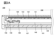
- 2A and 2B are cross-sectional views of electronic devices having a flexible battery of one embodiment of the present invention.
- FIG. 3 is a cross-sectional view of an electronic device having a flexible battery of one embodiment of the invention.
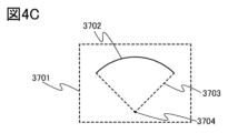
- 4A to 4C are diagrams illustrating the radius of curvature of the flexible battery of one embodiment of the present invention.
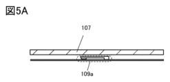
- 5A-5C are cross-sectional views illustrating flexible batteries and sensors according to one aspect of the present invention.
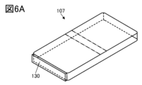
- 6A is a perspective view of a flexible battery or the like of one embodiment of the present invention
- FIG. 6B is a perspective view of a circuit board
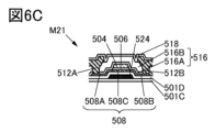
- FIG. 6C is a cross-sectional view of a semiconductor element.
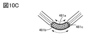
- FIGS. 10B and 10C are cross-sectional views of an electronic device or the like including a flexible battery of one embodiment of the present invention.
- 11A to 11C are perspective views of electronic devices and the like including the flexible battery of one embodiment of the present invention.
- 12A and 12B are cross-sectional views showing a flexible battery of one form of the present invention.
- FIG. 13A is a cross-sectional view showing a negative electrode of one embodiment of the present invention
- FIG. 13B is a top view showing a negative electrode of one embodiment of the present invention
- 14A is a cross-sectional view showing a positive electrode according to one embodiment of the present invention
- FIG. 14B is a top view showing a positive electrode according to one embodiment of the present invention
- 15A is a plan view showing the exterior body of one embodiment of the present invention
- FIG. 15B is a diagram showing the exterior body of one embodiment of the present invention
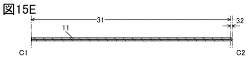
- FIGS. 15C to 15E show the exterior body of one embodiment of the present invention.
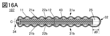
- FIG. 16C is a diagram illustrating how to bend the exterior body of one embodiment of the present invention.
- FIG. 17A is a schematic perspective view of the exterior body of one embodiment of the present invention
- FIG. 17B is a cross-sectional view of the exterior body of one embodiment of the present invention.
- 18A to 18E are schematic cross-sectional views showing an exterior body of one embodiment of the present invention.
- 19A to 19E are schematic cross-sectional views showing an exterior body of one embodiment of the present invention.
- FIG. 20 is a cross-sectional view showing an exterior body of one embodiment of the present invention.
- 21A and 21B are top views showing an exterior body of one embodiment of the present invention.
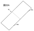
- 22A to 22C are top views showing an exterior body of one embodiment of the present invention.
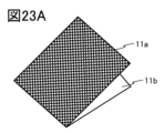
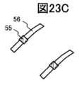
- FIG. 23A-23D are top views of a flexible battery of one embodiment of the present invention
- FIG. 23E is a cross-sectional view of a flexible battery of one embodiment of the present invention
- 24A and 24B are cross-sectional views showing an exterior body of one embodiment of the present invention.
- FIG. 25 is a flow showing a method for producing a positive electrode active material by a coprecipitation method of one embodiment of the present invention.
- 26A to 26C are flow charts showing a method for manufacturing a positive electrode active material by a solid-phase method of one embodiment of the present invention.
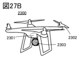
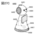
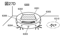
- 27A to 27D illustrate an electronic device of one embodiment of the present invention.
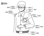
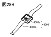
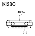
- 28A to 28D illustrate an electronic device of one embodiment of the present invention.
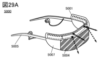
- 29A to 29C are diagrams illustrating electronic devices of one embodiment of the present invention.
- 30A to 30C are diagrams illustrating electronic devices of one embodiment of the present invention.
- a flexible battery is a battery with mobility, and specifically refers to a battery that can follow a movable housing while being sandwiched between the housings.
- a positive electrode active material refers to a compound containing a transition metal and oxygen, which is capable of intercalating and deintercalating Li.
- a compound is sometimes called a composite oxide. Therefore, the positive electrode active material does not contain carbonic acid, hydroxyl groups, and the like adsorbed after the positive electrode active material is produced.
- the positive electrode active material does not include electrolytes, organic solvents, binders, conductive materials, or compounds derived from these that adhere to the positive electrode active material.
- the interface between a region where a transition metal (eg, Co, Ni, Mn, Fe) that is oxidized and reduced with Li intercalation and deintercalation exists and a region where it does not exist is defined as the surface of the positive electrode active material.
- the surface layer portion refers to a region within 50 nm from the surface toward the inside, vertically or substantially vertically from the surface.
- Subsurface is synonymous with near-surface, near-surface region or shell.
- a region deeper than the surface layer of the positive electrode active material is called a bulk. Bulk is synonymous with internal or core.
- the covering portion of the positive electrode active material includes the portion formed by depositing decomposition products of the electrolytic solution due to charging and discharging. The covering portion does not have to cover all of the positive electrode active material.
- An electronic device 100 of one embodiment of the present invention includes at least a housing 101, a display portion 102, a power button 103, a button 104, a speaker 105, a microphone 106, a flexible battery 107, and a sensor 109, and the housing 101 is a hinge portion. 119 can be used to move.
- the display portion 102 is a region where display can be visually recognized, and includes a display and the like.
- FIG. 2A is a cross-sectional view of the unfolded configuration, and the cross-sectional view corresponds to a portion of the microphone 106 side shown in FIG. 1A.
- the flexible battery 107 is also deployed following the housing 101 .
- the flexible battery 107 shown in FIG. 2A is sometimes referred to as a straight configuration flexible battery.
- FIGS. 2A and 2B the housing 101 is bent using the hinge portion 119 (referred to as a second form).
- FIG. 2B is a cross-sectional view of the folded form, and since FIG. 2B shows the appearance of the flexible battery 107, the display and the like are omitted.
- FIG. 2B when housing 101 is folded, flexible battery 107 is also folded.
- the flexible battery 107 shown in FIG. 2B may be referred to as a curved flexible battery, a bent flexible battery, or the like.
- electronic device 100 of one embodiment of the present invention changes from the first mode to the second mode by controlling the position of housing 101. It is possible to grasp the transitional form or the intermediate form from the first form to the second form. Of course, it is also possible to grasp a form in which the second form transitions to the first form, or an intermediate form from the second form to the first form. Since these transitional forms and intermediate forms are distinguished from the first and second forms and the housing 101 takes the same form, they are collectively referred to as the third form.
- the electronic device of the present invention has a flexible battery as described above.
- the charging of the flexible battery 107 is performed in the first mode and the second mode, and is managed so as not to be performed in the third mode. Specifically, using the sensor 109 or the like, charging is started after it is confirmed that the flexible battery 107 is in the first form or the second form, and when it is confirmed to be in the third state It is preferable that the electronic device 100 is equipped with a system that manages to stop charging.
- the electronic device 100 of one embodiment of the present invention include a system that detects the first to third embodiments using the sensor 109 . If the sensor 109 can detect the first mode and the second mode, which are modes for starting charging, it can recognize that the sensor is in the third mode, which is another mode, and stops charging. can do. Further, if the sensor 109 can detect the third mode, which is the mode in which charging is stopped, it can be grasped as the first mode or the second mode, which are other modes, and charging can be started. can do.
- the sensor 109 it is preferable to install the sensor 109 in a region that overlaps with the hinge portion 119 when viewed from the top, because the movement of the electronic device 100 can be easily grasped.
- the sensor 109 since the installation position can be determined depending on the function of the sensor 109 , the sensor 109 does not necessarily have to be installed in the region overlapping the hinge portion 119 .
- the sensor 109 may be installed on either the housing 101 or the hinge portion 119 in a cross-sectional view.
- protective member 150 is preferably provided on the display surface side of housing 101 so as to overlap display unit 102 .
- a light-transmitting protective member 150 is preferably used for a region overlapping with the display portion 102 so that the display portion 102 is visible.
- a space 149 is located in a region surrounded by the housing 101 and the protection member 150 .
- a display panel 151 , an optical member 152 positioned over the display panel 151 , and a touch sensor panel 153 positioned over the optical member 152 are provided in the space 149 in a region overlapping with the display portion 102 .
- the protective member 150, the display panel 151, the optical member 152, and the touch sensor panel 153 are preferably fixed to each other with an adhesive layer.
- a polarizing plate, a circularly polarizing plate, or the like can be used as the optical member 152 .
- a portion of the display panel 151 is folded back in a region outside the display unit 102, and an FPC (Flexible Printed Circuit) 158 is connected to the folded portion. be able to. It is preferable that an IC 159 is mounted on the FPC 158 .
- the FPC 158 is connected to terminals provided on the printed circuit board 160 .
- the electronic device 100 preferably has a cover portion 120 located outside the housing 101 in addition to the housing 101.
- FIG. The cover portion 120 preferably has a function (referred to as a sliding function) to be displaced relative to the housing 101 .
- the flexible battery 107 is preferably positioned within the cover portion 120 as shown in FIG. 2B. With such a configuration, the flexible battery 107 can easily follow the movement of the housing 101, which is preferable.
- a second battery 170 may be arranged in the space 149 .
- the second battery 170 may not be a flexible battery, and may be fixed to the housing 101 .
- a mobile information terminal that can be used as a smart phone, a tablet, or the like is exemplified.
- a specific example of the flexible battery 107 is a lithium ion battery. Lithium ion batteries are suitable as batteries for personal digital assistants because of their high output or high capacity.
- the electronic device 100 of one embodiment of the present invention can be bent. ), and the housing 101 , the display unit 102 , and the flexible battery 107 can move according to the hinge portion 119 . Further, the housing 101 can be opened and closed according to the hinge portion 119 , and the display portion 102 and the flexible battery 107 can follow the movement of the housing 101 . Although parts other than the flexible battery 107 are omitted in FIG. 2B, the position of the flexible battery 107 inside the cover part 120 makes it easier to follow the movement of the housing 101, which is preferable.
- the cover section 120 slides with respect to the housing 101, and the second display section 102b can be confirmed from the slid portion. and preferred. Even in the state of being folded in two, the user can visually recognize a simple display such as a time display or notification display of mail reception on the second display portion 102b.
- the back surface of the display unit 102 can be used for the second display unit 102b. That is, the second display section 102b can be the same as the display section 102.
- the second display section 102b may be a separate display section from the display section 102.
- the cover part 120 is partly fixed to the housing 101, but is not fixed to the part overlapping the hinge part 119 and the second display part 102b. Specifically, a portion of the housing 101 located on the back surface of the electronic device 100 and the cover portion 120 need only be fixed, and the cover portion 120 is fixed to the housing in the portion overlapping with the hinge portion 119 and the second display portion 102b. It is sufficient if it is held so as to be slidable with respect to the body 101 . Furthermore, the cover part 120 may be detachable from the housing 101 .
- the hinge portion 119 which is also referred to as a connecting portion, has a structure in which a plurality of columnar bodies 119a are overlapped and connected in the overlapping region as shown in FIG. 2B.
- the hinge portion 119 can have various forms without being limited to this structure.
- the hinge portion 119 preferably has a mechanism that allows the display portion 102 and the flexible battery 107 to be bent without being stretched or contracted.
- hinge portion 119 is positioned so as to overlap the center of flexible battery 107, but the present invention is not limited to this.
- hinge portion 119 may be arranged at a position shifted from the center of flexible battery 107 .
- Flexible battery 107 can be bent in a region overlapping hinge portion 119 .
- the flexible battery 107 can also take the above first to third forms.
- the flexible battery 107 preferably has a radius of curvature of 5 mm or more, preferably 10 mm or more, more preferably 10 mm or more and 60 mm or less.
- FIG. 4A On a plane 3701 obtained by cutting a curved surface 3700, a part of a curve 3702 included in the curved surface 3700 is approximated to an arc of a circle, the radius of the circle is defined as the radius of curvature 3703, and the center of the circle is defined as the center of curvature 3704. do.
- a top view of curved surface 3700 is shown in FIG. 4B.
- FIG. 4C shows a cross-sectional view of curved surface 3700 cut by plane 3701 .
- the radius of curvature of the curve that appears in the cross section differs depending on the angle of the plane with respect to the curved surface or the cutting position. Let it be the radius of curvature.
- the cross-sectional shape of the flexible battery 107 is not limited to a circular arc shape, and may be a shape having a partial circular arc.
- a shape with a partial arc may result in a shape in which the curved surface has multiple centers of curvature.
- the flexible battery 107 should be bent in a range where the curvature radius of the curved surface with the smallest curvature radius among the curvature radii at each of the plurality of curvature centers is 5 mm or more, preferably 10 mm or more, and more preferably 10 mm or more and 60 mm or less. can be done.
- the flexible battery 107 capable of following the movement of the housing 101 should be charged in the first or second mode, and should not be charged in the third mode, in order to ensure safety. and That is, using the sensor 109 or the like, charging is started when the flexible battery 107 is confirmed to be in the first or second state, and charging is started when it is confirmed to be in the third state. Stop.
- Such charging of the flexible battery 107 can be controlled by a charging control circuit.
- the flexible battery 107 is charged in the first mode or the second mode and is not charged in the third mode. can be controlled.
- the state of charge (SOC) of the flexible battery 107 may be known. Even in the second mode, charging may be stopped when the charging rate is 85% or more, preferably 90% or more. The SOC can be grasped by the charge control circuit.
- the flexible battery 107 that can follow the movement of the housing 101 may be discharged in any of the first to third modes.
- one embodiment of the present invention can provide a safe charging environment for the flexible battery 107 that can follow the movement of the housing.
- the display portion 102 illustrated in FIG. 1 can perform display using a flexible display.
- a flexible display can be used for the display panel 151 shown in FIG. 2A.
- a flexible display preferably has a plurality of light-emitting devices arranged in a matrix as display elements, and the plurality of light-emitting devices are sandwiched between flexible films.
- the light-emitting element it is preferable to use an EL device (also referred to as an EL element) such as an organic light-emitting diode (OLED) or a quantum-dot light-emitting diode (QLED).
- OLED organic light-emitting diode
- QLED quantum-dot light-emitting diode
- Examples of light-emitting materials that EL devices have include fluorescent materials that emit fluorescence, phosphorescent materials that emit phosphorescence, inorganic compounds (such as quantum dot materials), and substances that exhibit thermally activated delayed fluorescence (thermally activated delayed fluorescence: TADF) materials) and the like.
- LEDs, such as micro LED can also be used as a light emitting device.
- the flexible display is thin, and even if it is installed in the housing 101, a sufficient space can be secured inside the housing 101. - ⁇ Therefore, the degree of freedom regarding installation of the sensor 109 can be increased.
- FIG. 1A illustrates a case where the sensor 109 is installed in a region overlapping with the hinge portion 119 in top view, but it may be installed in a region where the movement of the flexible battery 107 can be detected.
- the form detected as the movement of the flexible battery 107 may include the first form and the second form, and does not necessarily include the first to third forms.
- FIG. 5A shows a cross-sectional view corresponding to the first form of the electronic device 100 when the push switch 109a is used as the sensor 109. As shown in FIG. Note that FIG. 5A omits parts other than the flexible battery 107 and the sensor 109a.
- the electronic device 100 has a flexible battery 107 in the cover portion 120, and has a push switch 109a in the housing 101, for example, the space 149 or the like.
- the push switch 109a is preferably positioned so as to overlap the area where the flexible battery 107 is bent. Depending on the movement of flexible battery 107, a signal from push switch 109a can be obtained.
- a push switch 109a that turns on when the flexible battery 107 is not bent as shown in FIG. 5A is used, a signal based on the turning on can be obtained.
- the push switch 109a is turned off, and a signal based on the turning off can be obtained.
- a signal obtained from the push switch 109a can be input to a charging control circuit or the like to control the charging of the flexible battery 107 to be stopped or started.
- the sensor 109 can use the angular velocity sensor 109b.
- angular velocity sensors 109b1 and 109b2 it is preferable to install angular velocity sensors 109b1 and 109b2 in housing 101, typically in space 149, or in cover part 120, as shown in FIG. 5B.
- Angular velocity sensor 109b1 may be positioned so as to overlap the first area divided by hinge portion 119
- angular velocity sensor 109b2 may be positioned so as to overlap the second area divided by hinge portion 119. Since the angular velocity changes according to the movement of the flexible battery 107, the change can be input to a charge control circuit or the like to control the charging of the flexible battery 107 to be stopped or started.
- the sensor 109 can use a magnetic sensor 109c.
- a magnetic sensor it is preferable to install a magnet 109c2 in the housing 101 and a magnetic sensor, typically a 3D magnetic sensor 109c1, in the cover section 120 as shown in FIG. 5C.
- both the 3D magnetic sensor 109c1 and the magnet 109c2 may be installed in the housing 101, typically in the space 149.
- FIG. Since the applied magnetic field changes according to the movement of the flexible battery 107, the change can be input to a control circuit or the like to control the charging of the flexible battery 107 to stop or start.
- FIG. 6A A perspective view of the flexible battery 107 is shown in FIG. 6A.
- the region overlapping with the hinge portion 119 is indicated by a dashed line in accordance with FIG. 1A.
- a circuit board 130 is electrically connected to the flexible battery 107, and a structure in which the flexible battery 107 and the circuit board 130 are integrated may be referred to as a battery pack.
- a perspective view of the circuit board 130 is shown in FIG. 6B.
- a charging control circuit 135 is installed on the circuit board 130 .
- the charge control circuit 135 has a control circuit and the like, is electrically connected to the sensor 109 and can receive a signal and the like from the sensor 109 .
- the charging control circuit 135 has a function of stopping charging to the flexible battery 107 or starting charging based on a signal from the sensor 109 or the like. Specifically, charging can be started by turning on a switching element included in the charging control circuit 135, and can be stopped by turning off the switching element.
- a transistor may be used as the switching element.
- FIG. 6C shows the structure of a transistor M21 that can be used as a circuit element such as a switching element included in the charging control circuit 135. As shown in FIG.
- the transistor M21 is formed, for example, on the insulating film 501C.
- the transistor M21 has a semiconductor film 508 located over the insulating film 501C.
- a semiconductor containing a group 14 element for example, can be used for the semiconductor film 508 .
- a semiconductor containing silicon can be used for the semiconductor film 508
- typically polysilicon can be used for the semiconductor film 508 .
- single crystal silicon can be used for the semiconductor film 508 .
- a metal oxide can be used for the semiconductor film 508, and typically an oxide semiconductor can be used. Specifically, an oxide semiconductor containing indium, an oxide semiconductor containing indium, gallium, and zinc, or an oxide semiconductor containing indium, gallium, zinc, and tin can be used for the semiconductor film.
- a compound semiconductor containing silicon and oxygen can be used for the semiconductor film 508, and typically a SiC semiconductor can be used.
- a compound semiconductor containing gallium and nitrogen can be used for the semiconductor film 508, and typically a GaN semiconductor can be used.
- Transistor M21 comprises conductive layer 504, conductive layer 512A and conductive layer 512B.
- the conductive layer 504 has a region overlapping with the region 508C of the semiconductor film 508, and the conductive layer 504 has a gate function.
- a region 508C corresponds to a channel formation region.
- the conductive layer 512A has one of the function of the source electrode and the function of the drain electrode, and the conductive layer 512B has the other of the function of the source electrode and the function of the drain electrode.
- Semiconductor film 508 has regions 508A and 508B, which may be referred to as impurity regions, source regions and drain regions. Region 508A is electrically connected to conductive layer 512A and region 508B is electrically connected to conductive layer 512B.
- Insulating film 506 comprises a region sandwiched between semiconductor film 508 and conductive layer 504 .
- the insulating film 506 has a function of a gate insulating film.
- the insulating layer 516 is provided to cover the conductive layer 504 .
- the insulating layer 516 has a structure in which a first insulating layer 516A and a second insulating layer 516B are stacked.
- the conductive layer 524 can be used for the back gate of the transistor, and the conductive layer 524 can be provided below the semiconductor film 508 .
- a structure in which gates are positioned above and below a semiconductor film is sometimes called a dual gate structure.
- the conductive layer 524 has a region that sandwiches the semiconductor film 508 with the conductive layer 504 .
- Conductive layer 524 has the function of a gate.
- the insulating film 501D is sandwiched between the semiconductor film 508 and the conductive layer 524 and has a function of a gate insulating film.
- An insulating layer 518 is provided to cover the conductive layers 512A and 512B.
- Such a charging control circuit 135 has a function of managing charging of the flexible battery 107, and specifically can stop charging and start charging.
- the charge control circuit 135 can also function as a protection circuit by using the function of stopping charging.
- the electronic device 100 may have a plurality of batteries, and at least one of the plurality of batteries may be the flexible battery 107 .
- FIG. 1A and 1B show an example in which the display surface of the display unit 102 is bent on the inside, but it is not particularly limited. You may apply the structure bent so that it may become. Depending on the structure of the hinge portion 119, a structure that is bent both inside and outside the display surface may be applied.
- the electronic device 100 equipped with such a flexible display is extremely lightweight, and the electronic device 100 with excellent portability can be realized.
- the flexible battery 107 as the secondary battery of the electronic device 100
- the electronic device 100 can be partially folded, and the size can be reduced. In other words, the electronic device 100 with excellent portability can be realized.
- FIG. 7A shows an example of a flexible battery management system 10 in accordance with one aspect of the present invention.
- Flexible battery management system 10 includes charging control circuitry 135 , flexible battery 107 and sensor 109 .
- Charging control circuit 135 is electrically connected to flexible battery 107 .
- the charge control circuit 135 is electrically connected to the positive and negative electrodes of the flexible battery 107, respectively.
- the flexible battery 107 may be provided with a positive terminal such as a positive lead or a positive tab.
- a negative electrode the flexible battery 107 may be provided with a negative terminal such as a negative lead or a negative tab.
- the charging control circuit 135 is electrically connected to the positive terminal and the negative terminal.
- Sensor 109 has a function of detecting the state of flexible battery 107 . Specifically, it has a function of detecting the movement of the flexible battery 107 that follows the movement of the housing. Sensor 109 is electrically connected to charge control circuit 135 .
- the charge control circuit 135 shown in FIG. 7A has at least a voltage measurement circuit 15, a current measurement circuit 16, and a control circuit 18.
- FIG. 7A Furthermore, the charge control circuit 135 has a first switch 35 and a second switch 36 electrically connected to the control circuit 18 .
- a first switch 35 functions to stop charging in case of overcharge and a second switch 36 functions to stop discharging in case of overdischarge. Based on the signal from sensor 109 , first switch 35 can be used to stop charging flexible battery 107 .
- the charge control circuit 135 shown in FIG. 7B further has a temperature sensor 20 unlike that shown in FIG. 7A.
- the voltage measurement circuit 15 is electrically connected to the positive and negative electrodes of the flexible battery 107, respectively, as shown in FIGS. 7A and 7B.
- the voltage measurement circuit 15 may be electrically connected to the positive terminal and the negative terminal.
- the voltage measurement circuit 15 has a function of measuring the voltage (referred to as terminal voltage) of the flexible battery 107, for example, the terminal voltage (referred to as charging voltage) while the flexible battery 107 is being charged. .
- the voltage measuring circuit 15 may have a function of measuring terminal voltage (discharge voltage) when the flexible battery 107 is discharging.
- the voltage measurement circuit 15 can provide the measured voltage value to the control circuit 18 . If the measured voltage value is an analog value, the analog value may be digitally converted and supplied to the control circuit 18 . That is, the voltage measurement circuit 15 may have a circuit that converts an analog value into a digital value, and this circuit can use an analog-to-digital conversion circuit (ADC).
- ADC analog-to-digital conversion circuit
- the configuration of the ADC includes a delta-sigma modulation type, a parallel comparison type (also referred to as a flash type), a pipeline type, and the like.
- the ⁇ modulation type is suitable for the voltage measurement circuit 15 because of its high resolution.
- ⁇ Measurement Example 1 of Voltage Vb1> A measurement example 1 of the voltage Vb1 between the positive electrode and the negative electrode of the flexible battery 107 will be described with reference to FIG. 8A. Only the voltage measurement circuit 15 is shown in the charging control circuit 135 of FIG. 8A, and the others are omitted. The voltage measurement circuit 15 can directly measure the voltage Vb1 between the positive and negative electrodes of the flexible battery 107 as shown in FIG. 8A.
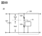
- the voltage measurement circuit 15 can also measure the resistance-divided voltage Vb1. Only the voltage measurement circuit 15 is shown in the charge control circuit 135 of FIG. 8B, and the others are omitted. In FIG. 8B, voltage Vb1 is divided into voltages Vb2 and Vb3 by resistive element 122 and resistive element 123, and voltage measurement circuit 15 can measure voltage Vb3, for example. Voltage measurement circuit 15 is electrically connected between the negative electrode of flexible battery 107 and resistor element 122 and resistor element 123 to enable measurement of voltage Vb3.
- the voltage measurement circuit 15 measures the voltage obtained by dividing the voltage between the positive electrode and the negative electrode of the flexible battery 107 by resistance
- the voltage measurement circuit 15 or the control circuit 18 measures the voltage of the flexible battery 107 from the resistance-divided voltage.
- a voltage Vb1 between the positive and negative electrodes may be estimated.
- the current measurement circuit 16 is electrically connected to the positive terminal of the flexible battery 107 as shown in FIGS. 7A and 7B, and a resistance element is positioned between the connection points to measure the potential difference across the resistance element. Note that the current measurement circuit 16 may be electrically connected to the positive terminal.
- the current measurement circuit 16 has a function of measuring currents flowing through the positive and negative electrodes of the flexible battery 107, and may have a function of measuring, for example, a current (charging current) when the flexible battery 107 is being charged. preferable.
- the current measurement circuit 16 may have a function of measuring the current (discharge current) when the flexible battery 107 is discharging in addition to the charging current.
- Current measurement circuit 16 can provide the measured current value to control circuit 18 .
- the measured current value is an analog value, but the analog value may be converted into a digital value and supplied to the control circuit 18, and the analog-to-digital conversion circuit (ADC) described above can be used.
- ADC analog-to-digital conversion circuit
- Sensor 109 is electrically connected to control circuit 18 as shown in FIGS. 7A and 7B. Again, the sensor 109 has a function of detecting the state of the flexible battery 107 . Specifically, it has a function of detecting the movement of the flexible battery 107 that follows the movement of the housing.
- the control circuit 18 shown in FIGS. 7A and 7B has the function of controlling the start and stop of charging of the flexible battery 107 . Furthermore, the control circuit 18 preferably has an arithmetic function, a detection function, a determination function, or the like.
- the calculation function can calculate data indicating battery characteristics of the flexible battery 107 from values given from the voltage measurement circuit 15 or the like.
- the determination function of the control circuit 18 can determine when charging should be stopped based on the signal obtained from the sensor 109 .
- the control circuit 18 has a function of stopping charging based on the signal obtained from the sensor 109 .
- Charging the flexible battery 107 may use constant current-constant voltage (CC-CV) charging.
- CC-CV charging constant current charging is performed, and after the charging voltage reaches the upper limit value in constant current charging, constant voltage charging is performed.
- the charging condition from the start of charging to the stop of charging is constant current charging.
- the voltage changes after the charging is stopped and then resumed, which makes it easy to grasp the SOC (rate of charge).
- the charge control circuit 135 preferably has a function as a coulomb counter.
- the charge control circuit 135 can calculate the integrated electric quantity of the flexible battery 107 using the current measurement circuit 16 and the control circuit 18 .
- the charge capacity and discharge capacity of the flexible battery 107 can be calculated from the calculated amount of electricity.
- control circuit 18 may have a function of analyzing the SOC using the calculated charge capacity and discharge capacity.
- control circuit 18 a CPU (Central Processing Unit), MCU (Micro Controller Unit), or the like can be used.
- control circuit 18 preferably has a storage circuit 19 in addition to the CPU or MCU.
- a temperature sensor 20 shown in FIG. 7B can measure the operating temperature of the flexible battery 107 .
- the temperature sensor 20 only needs to be able to measure a range from low temperature to high temperature.
- the temperature sensor 20 is preferably installed so as to be in contact with the exterior body of the flexible battery 107 or a housing outside the exterior body.
- the usage temperature information obtained from the temperature sensor 20 is useful. Also, even when the flexible battery 107 is used in the same temperature range, the temperature sensor 20 can detect an abnormality when the battery is abnormal due to the movement.
- a flexible battery management system 10B shown in FIG. 9 is an example in which a charging control circuit 135 is electrically connected to an assembled battery, that is, m flexible batteries 107 connected in series.
- FIG. 9 shows an example of a flexible battery management system 10B in which m is an integer of 4 or more. 107(1), flexible battery 107(2), flexible battery 107(3), and flexible battery 107(m).
- the charging control circuit 135 may be divided into m charging control circuits 135(m), but it is preferable that they are shared as shown in FIG.
- voltages and the like of the m flexible batteries 107 can be measured using the m voltage measurement circuits 15 connected respectively.
- the voltage measurement circuits 15 may be shared without being divided into m voltage measurement circuits 15 as shown in FIG. Using the total voltage of m flexible batteries 107 connected in series (for example, in FIG. 9, the voltage between the positive electrode of flexible battery 107(1) and the negative electrode of flexible battery 107(m))) etc. may be measured.
- the flexible battery 107 of one embodiment of the present invention can be folded in two or more, for example, in three. By increasing the number of hinges 119, it can be folded in three.
- hinge portion 119 may be provided with a ratchet mechanism, a slip stopper, or the like so that the bending angle can be adjusted as appropriate.
- the flexible battery 107 of one embodiment of the present invention has high reliability against repeated deformation, and thus can be suitably used for such a foldable device.
- FIG. 10A is a top view of an electronic device 100A of one embodiment of the present invention, showing a mode (first mode) in which the display portion 102 is unfolded.
- FIG. 10B is a side view for explaining the structure of the electronic device 100A, and the arrow indicates the direction of display. As shown in FIGS. 10A and 10B, it has a first housing 101a and a second housing 101b, which are connected to the hinge portion 119A. Using hinge portion 119A, first housing 101a and second housing 101b can be moved.
- FIG. 10C is a side view illustrating hinge portion 119A shown in FIG. 10B.
- An electronic device 100A of one embodiment of the present invention includes a display portion 102 and an arithmetic device 410 positioned outside the display portion 102 as shown in FIG. 10A. Further, the display unit 102 is provided with a flexible display, a touch panel 422 which is input means for detecting a finger touched by a user and supplying an operation command, and a flexible battery 107A (broken line portion). Flexible battery 107A can apply the same configuration as flexible battery 107 shown in the above embodiment.
- the bending information and the operation instruction of the electronic device 100A are supplied to the arithmetic unit 410, and the image information based on the signals is supplied to the flexible display and displayed on the display unit 102.
- the flexible battery 107 is held by the first housing 101a, the second housing 101b, and the like.
- the hinge portions 119A form pairs and are installed on opposite sides. By bending the hinge portion 119A, the first housing 101a and the second housing 101b can be moved, and the flexible battery 107 can be moved following the housings.
- the flexible display and touch panel 422 can also move following the first housing 101a and the second housing 101b. In order to move the flexible battery 107A following the housing, the flexible battery 107 should be placed in the center of the electronic device 100A as seen from the side as shown in FIG. 10B.
- a support shaft, an elastic body, or the like can be used for the hinge portion 119A.
- the hinge portion 119A preferably has a configuration in which an elastic body 481c is positioned between the first stretch sensor 481a and the second stretch sensor 481b.
- one of the pair of expansion and contraction sensors supplies a signal that detects extension and a signal that the other detects contraction to the charging control circuit 135 electrically connected to the flexible battery 107A.
- the detected signal may be supplied to the arithmetic unit 410 shown in FIG. 10A and the like. By comparing these signals, bending information of the electronic device 100A can be obtained. It is possible to control the stop or start of charging of the flexible battery 107 based on the information.
- the flexible battery 107A of one embodiment of the present invention preferably has a radius of curvature of 5 mm or more, preferably 10 mm or more, more preferably 10 mm or more and 60 mm or less.
- the flexible battery 107A of one embodiment of the present invention can be folded in two or more, for example, in three. By increasing the number of hinge portions 119A, it can be folded in three.
- the hinge portion 119A may be provided with a ratchet mechanism, a slip stopper, or the like so that the bending angle can be appropriately adjusted.
- the flexible battery 107A of one embodiment of the present invention has high reliability against repeated deformation, and thus can be suitably used for such a foldable device.
- This embodiment can be implemented by appropriately combining at least part of it with other embodiments described herein.
- FIG. 11A is a perspective view illustrating the structure of an electronic device 100B of one embodiment of the present invention.
- deployed is shown.
- FIG. 11B shows a state (third mode) in which the display section 102 is being bent.
- FIG. 11C shows a form (second form) in which the display section 102 is folded.
- first housing 101a and second housing 101b there are two sets of first housing 101a and second housing 101b.
- the second housing 101b is positioned so as to overlap with the first housing 101a, and can sandwich the flexible battery 107B and the like.
- Two sets of the first housing 101a and the second housing 101b are connected to the hinge portion 119B.
- the hinge portion 119B the two sets of the first housing 101a and the second housing 101b can be moved.
- the flexible battery 107B is preferably placed in the center of the electronic device 100B when viewed from the side.
- a space is located in an area surrounded by the first housing 101a and the second housing 101b.
- a sensor can be installed in the space.
- the display unit 102 is bent so as to be visible outside.
- one embodiment of the present invention is not limited to this.
- the display unit 102 may be folded so as to be hidden inside.
- the electronic device 100B shown in FIGS. 11A to 11C has a flexible display in addition to the flexible battery 107 in the display portion 102.
- FIG. Furthermore, the electronic device 100B has a first housing 101a and a second housing 101b. The first housing 101a and the second housing 101b are connected via a hinge portion 119B.
- the first housing 101a and the second housing 101b are preferably made of a material having lower flexibility than the flexible battery 107B. Further, when the first housing 101a and the second housing 101b are made of a light-shielding material, the driving circuit of the electronic device 100B can be arranged, and the driving circuit is irradiated with external light. can be suppressed.
- the first housing 101a and the second housing 101b can be made of plastic, metal, alloy, rubber, or the like.
- the use of plastic, rubber, or the like is preferable because it is possible to obtain a support panel that is lightweight and resistant to breakage.
- silicone rubber, stainless steel, or aluminum may be used for the first housing 101a and the second housing 101b.
- flexible battery 107 can be charged in the first embodiment shown in FIG. 11A and the second embodiment shown in FIG. 11C, and charging of flexible battery 107 is stopped in the embodiment shown in FIG. 11B. .
- the flexible display can be folded either by bending the display surface inward (inward bending) or by bending the display surface outward (outward bending).
- the display section 102 can be bent inward to prevent the display section 102 from being scratched or soiled.
- the flexible battery 107B of one embodiment of the present invention preferably has a radius of curvature of 5 mm or more, preferably 10 mm or more, more preferably 10 mm or more and 60 mm or less.
- the flexible battery 107B of one embodiment of the present invention can be folded in two or more, for example, in three. By increasing the number of hinge portions 119B, it can be folded in three.
- hinge portion 119B may be provided with a ratchet mechanism, a slip stopper, or the like so that the bending angle can be appropriately adjusted.
- the flexible battery 107 of one embodiment of the present invention has high reliability against repeated deformation, and thus can be suitably used for such a foldable device.
- This embodiment can be implemented by appropriately combining at least part of it with other embodiments described herein.
- the cross-sectional view shown in FIG. 12A shows a state (first state) in which the flexible battery 107 is straight.
- the cross-sectional view shown in FIG. 12B shows a state (second state or third state) in which flexible battery 107 is bent.
- Flexible battery 107 can also remain bent.
- the flexible battery 107 can alternate between the straight state shown in FIG. 12A and the bent state shown in FIG. 12B.
- the state in which flexible battery 107 is bent as in FIG. 12B may be described as having a bent portion.
- the bending position can be positioned at the central portion of the flexible battery 107, or can be positioned at a position other than the central portion.
- the flexible battery 107 has a negative electrode 301 and a positive electrode 331, and has a structure in which the negative electrode 301 and the positive electrode 331 are laminated (sometimes referred to as a laminated structure or a laminated electrode).
- the number of layers of the negative electrodes 301 and the number of layers of the positive electrodes 331 may be equal, but the number of layers of the negative electrodes 301 may differ from the number of layers of the positive electrodes 331 .
- the number of laminated layers of the negative electrode 301 may be larger than the number of laminated layers of the positive electrode 331 .
- FIG. 12A shows a configuration in which the area of the negative electrode 301 and the area of the positive electrode 331 are equal.
- the area of the negative electrode 301 and the area of the positive electrode 331 may be the same, but the area of the negative electrode 301 may be different from the area of the positive electrode 331 .
- the negative electrode 301 and the positive electrode 331 move corresponding to the positional deviation. If the negative electrode 301 and the positive electrode 331 are adjacent to each other, the adjacent negative electrode 301 and the positive electrode 331 may rub against each other.
- Flexible battery 107 of one embodiment of the present invention has buffer layer 305 positioned at least between adjacent negative electrode 301 and positive electrode 331 in order to reduce friction between adjacent negative electrode 301 and positive electrode 331 .
- the flexible battery 107 has a structure in which the buffer layer 305 wraps the active material layer of the negative electrode 301 or wraps the active material layer of the positive electrode 331 . By wrapping one of the active material layers with the buffer layer 305, friction between the negative electrode 301 and the positive electrode 331 can be reduced.
- the flexible battery 107 preferably has a structure in which the buffer layer 305 wraps the active materials and the like in the negative electrode 301 and the positive electrode 331 .
- a graphene compound, graphene, or carbon fiber can be used for the buffer layer 305, and even if the graphene compound, graphene, or carbon fiber is attached to the active material layer, the above-described friction during movement can be suppressed. .
- Graphene compounds and the like will be described later.
- the buffer layer 305 can exhibit electrical conductivity if it is made of, for example, a carbon material, and can exhibit insulating properties depending on the ratio of oxygen or the like contained therein.
- the negative electrode 301 includes a current collector 302 (sometimes referred to as a negative electrode current collector) and an active material layer 303 (sometimes referred to as a negative electrode active material layer).
- the positive electrode 331 includes a current collector 332 (sometimes referred to as a positive electrode current collector) and an active material layer 333 (sometimes referred to as a positive electrode active material layer). An ordinal number is sometimes given to distinguish the current collectors from each other.
- the buffer layer 305 exhibits conductivity
- the flexible battery 107 with a separator may be used. Further, when the buffer layer 305 exhibits insulating properties, the buffer layer 305 can function as a separator, so that the flexible battery 107 can eliminate the need for a separator, which is preferable.
- FIG. 13A shows a cross-sectional view of the negative electrode 301
- FIG. 13B shows a top view of the negative electrode 301.
- the cross-sectional view of FIG. 13A corresponds to the position marked with a dotted line in FIG. 13B.
- a negative electrode 301 has a current collector 302 and an active material layer 303 .
- the active material layer 303 is preferably formed on two surfaces (one surface and the other surface) of the current collector 302 . Forming the active material layer 303 on two sides is referred to as a double-sided formation structure or a double-sided coating structure.
- the active material layer 303 may be formed on either one side or the other side of the current collector 302 . Forming the active material layer 303 on one side is referred to as a single-sided formation structure or a single-sided coating structure.
- the current collector 302 and the active material layer 303 are wrapped with the buffer layer 305.
- the buffer layer 305 envelops the current collector 302 and the active material layer 303 .
- the buffer layer 305 preferably has a property of being flexible and easily deformable. Further, it is expected that the mechanical strength of the electrode or the like provided with the buffer layer 305 is increased.
- graphene is one atomic layer of carbon arranged and has a ⁇ bond between carbon atoms. That is, graphene includes carbon, has a shape such as a sheet shape (also referred to as a plate shape), and has a two-dimensional structure formed of six-membered carbon rings. The two-dimensional structure formed by the six-membered carbon rings may be called a carbon sheet.
- graphene in which two to 100 layers are stacked is sometimes called multilayer graphene.
- Graphene and multi-layer graphene have, for example, a length of 50 nm or more and 100 ⁇ m or less, preferably 800 nm or more and 50 ⁇ m or less, in a longitudinal direction or in a plane.
- graphene compounds are described.
- a compound having graphene or multilayer graphene as a basic skeleton is called a “graphene compound” (also referred to as “graphene compound”).
- Other graphene compounds include graphene oxide, multilayer graphene oxide, reduced graphene oxide, reduced multilayer graphene oxide, graphene quantum dots, and the like, which will be described later.
- a graphene compound is, for example, a compound in which graphene or multilayer graphene is modified with an atom other than carbon or an atomic group having an atom other than carbon.
- graphene or multilayer graphene may be a compound modified with an atomic group mainly composed of carbon such as an alkyl group or an alkylene group. Note that an atomic group that modifies graphene or multilayer graphene is sometimes referred to as a substituent, a functional group, a specific group, or the like.
- modification refers to an atomic group having an atom other than carbon, or an atom other than carbon to graphene, multilayer graphene, graphene compound, or graphene oxide (described later) by substitution reaction, addition reaction, or other reaction.
- substitution reaction addition reaction, or other reaction.
- a graphene compound is, for example, one that contains carbon, has a shape such as a sheet shape, and has a two-dimensional structure formed of six-membered carbon rings.
- the two-dimensional structure formed by the six-membered carbon rings may be called a carbon sheet.
- graphene oxide examples include graphene or multilayer graphene modified with oxygen or oxygen-containing functional groups.
- oxygen-containing functional group include an epoxy group, a carbonyl group such as a carboxyl group, a hydroxyl group, a lactol group, and the like.
- a graphene compound modified with oxygen or a functional group containing oxygen is sometimes called graphene oxide.
- graphene oxide also includes multi-layered graphene oxide. Graphene oxide can exhibit insulating properties.
- ⁇ Terminated with fluorine> As the graphene compound, a material obtained by terminating graphene with fluorine may be used.
- Graphene oxide can be obtained by oxidizing the above graphene or multi-graphene.
- graphene oxide can be obtained by separating the layers of graphite oxide.
- Graphite oxide can be obtained by oxidizing graphite.
- graphene oxide may be further modified with the above atoms or atomic groups.
- Methods for producing graphene oxide include various synthesis methods such as Hummers method, modified Hummers method, and oxidation of graphite.
- the Hummers method and the modified Hummers method are methods of forming graphite oxide by oxidizing graphite such as flake graphite.
- the formed graphite oxide is a mixture of carbonyl, carboxy, hydroxyl, lactol, and other functional groups that are formed by oxidizing graphite in places, impairing the crystallinity of graphite and increasing the distance between layers. It's becoming Therefore, graphene oxide can be obtained by separating the layers easily by ultrasonic treatment or the like.
- a solution of potassium permanganate in sulfuric acid or the like is added to the graphite powder for an oxidation reaction to form a mixed solution containing graphite oxide.
- Graphite oxide has functional groups such as an epoxy group, a carbonyl group, a carboxy group, and a hydroxyl group due to oxidation of graphite carbon. Therefore, the interlayer distance of graphene oxide is longer than that of graphite.
- the graphite oxide having a long interlayer distance can be cleaved to separate graphene oxide, and a dispersion containing graphene oxide can be formed. .
- the obtained graphene oxide may contain elements such as sulfur and nitrogen, for example.
- the concentration of sulfur in the graphene compound of one embodiment of the present invention is preferably 5% or less, more preferably 3% or less.
- the graphene compound of one embodiment of the present invention may have, for example, 10 ppm or more and 5% or less, or 100 ppm or more and 3% or less, or 0.1% or more and 3% or less of sulfur.
- the concentration of sulfur contained in the graphene compound can be evaluated using, for example, elemental analysis such as XPS.
- the graphene compound of one embodiment of the present invention may contain, for example, 0.1% or more and 3% or less of nitrogen.
- RGO Reduced Graphene Oxide
- RGO may be written as "rGO” as shown in Non-Patent Document 1. Note that in RGO, all the oxygen contained in graphene oxide is not eliminated and part of oxygen or an atomic group containing oxygen remains in a state of being bonded to carbon in some cases.
- RGO may have functional groups such as epoxy groups, carbonyl groups such as carboxyl groups, or hydroxyl groups.
- the reduced graphene oxide preferably has a portion where the carbon concentration is higher than 80 atomic % and the oxygen concentration is higher than or equal to 2 atomic % and lower than or equal to 15 atomic %. With such carbon concentration and oxygen concentration, the conductivity of the reduced graphene oxide can be increased.
- the reduced graphene oxide preferably has an intensity ratio G/D of 1 or more between the G band and the D band in a Raman spectrum. Reduced graphene oxide with such an intensity ratio can be highly conductive.
- graphene oxide may be reduced by heat treatment or by using a reducing agent, for example.
- Reduced graphene oxide includes, for example, carbon and oxygen, has a shape such as a sheet, and has a two-dimensional structure formed of six-membered carbon rings.
- pores can be provided in the graphene compound in some cases.
- Pores in the graphene compound may correspond to regions through which carrier ions, specifically lithium ions, can pass. Having such holes facilitates the insertion and desorption of carrier ions, and can improve the rate characteristics of the battery.
- Pores provided in a portion of the carbon sheet are sometimes referred to as voids, defects or voids.
- the graphene compound may have pores provided by a plurality of carbon atoms and one or more fluorine atoms.
- the plurality of carbon atoms are preferably cyclically bonded, and one or more of the plurality of cyclically bonded carbon atoms are preferably terminated with the fluorine.
- Fluorine has high electronegativity and tends to be negatively charged. The proximity of the positively charged lithium ions causes interaction, stabilizes the energy, and lowers the barrier energy for carrier ions, specifically lithium ions, to pass through the pores. Therefore, since the pores of the graphene compound contain fluorine, carrier ions can easily pass through even small pores and the graphene compound can have excellent conductivity.
- the graphene compound may have a five-membered ring made of carbon, or a multi-membered ring of seven or more members made of carbon, in addition to the six-membered ring made of carbon.
- a region through which ions can pass may occur in the vicinity of the multi-membered ring of seven or more.
- a region through which ions can pass can be regarded as the hole.
- Examples of ions include carrier ions, specifically lithium ions.
- Other examples of the above-mentioned ions include ions of alkali metals other than lithium, anions possessed by the electrolyte, cations, and the like.
- the graphene compound may be in the form of a single sheet in which a plurality of graphene compounds are partially overlapped. Alternatively, a plurality of graphene compounds may be gathered to form a sheet shape. Since the graphene compound has a planar shape, surface contact is possible. Such a graphene compound may be referred to as a graphene compound sheet or a graphene compound net as described above.
- the graphene compound sheet has, for example, a region with a thickness of 0.33 nm or more and 100 ⁇ m or less, more preferably 0.34 nm or more and 10 ⁇ m or less.
- a graphene compound sheet may have an ion-passable region, for example, between adjacent graphene compounds. Therefore, the graphene compound sheet may have excellent ion conductivity. Alternatively, the graphene compound sheet may easily adsorb ions. Again, examples of ions include carrier ions, specifically lithium ions. Further, examples of the ions described above include ions of alkali metals other than lithium, anions possessed by the electrolyte, cations, and the like.
- the graphene compound sheet can be deformed when an external force is applied due to the slipping of the graphene compounds that overlap each other in a plane, and cracks and the like are unlikely to occur in some cases.
- Such a graphene compound sheet may be modified with atoms other than carbon, atomic groups having atoms other than carbon, or atomic groups mainly composed of carbon such as alkyl groups. Further, each of the plurality of layers of the graphene compound sheet may be modified with different atoms or atomic groups.
- Graphene compounds may have high conductivity even if they are thin, and surface contact can increase the contact area between graphene compounds or between the graphene compounds and an active material. Therefore, even if the amount per volume is small, the conductive path can be efficiently formed.
- a graphene compound can also be used as an insulator.
- a graphene compound sheet can be used as a sheet-like insulator.
- graphene oxide may have higher insulating properties than a non-oxidized graphene compound.
- the graphene compound modified with an atomic group can have improved insulating properties depending on the type of the modified atomic group.
- a graphene compound can be manufactured using a spray drying method, a coating method, or the like.
- a graphene oxide dispersion is used as a raw material and a graphene compound sheet is manufactured by a spray drying method will be described.
- the graphene oxide contained in the graphene oxide dispersion may be multi-layered graphene oxide, and the graphene oxide dispersion may contain graphene oxide or graphene oxide and multi-layered graphene oxide.
- a polar solvent is preferably used as the solvent for the graphene oxide dispersion.
- Polar solvents selected from, for example, water, methanol, ethanol, acetone, tetrahydrofuran (THF), dimethylformamide (DMF), 1-methyl-2-pyrrolidone (NMP) and dimethylsulfoxide (DMSO), ethylene glycol, diethylene glycol, and glycerin.
- THF tetrahydrofuran
- DMF dimethylformamide
- NMP 1-methyl-2-pyrrolidone
- DMSO dimethylsulfoxide
- a graphene compound including graphene oxide can be obtained by forming a plurality of graphene oxide films over a substrate or a plate by a spray drying method. When a plurality of graphene compounds overlap each other during film formation, a graphene compound sheet can be produced.
- the film thickness of the graphene compound or the graphene compound sheet can be controlled by adjusting the film formation time, the concentration of the dispersion liquid, or the like. Suitable for fabrication.
- FIGS. 14A and 14B show details of the positive electrode 331.
- 14A shows a cross-sectional view of the positive electrode 331
- FIG. 14B shows a top view of the positive electrode 331.
- the cross-sectional view of FIG. 14A corresponds to the position marked with a dotted line in FIG. 14B.
- a positive electrode 331 has a current collector 332 and an active material layer 333 .
- the active material layer 333 is preferably formed on two surfaces (one surface and the other surface) of the current collector 332 .
- forming the active material layer 333 on two sides is referred to as a double-sided formation structure or a double-sided coating structure.
- the active material layer 333 may be formed on either one surface or the other surface of the current collector 332 .
- forming the active material layer 333 on one side is referred to as a single-sided formation structure or a single-sided coating structure.
- the current collector 332 and the active material layer 333 are wrapped with the buffer layer 305 .
- the buffer layer 305 envelops the current collector 332 and the active material layer 333 .
- the flexible battery 107 of one embodiment of the present invention can be easily moved because the buffer layer 305 reduces friction when the flexible battery 107 is repeatedly bent.
- the buffer layer 305 can be flexible and easily deformable, and can increase the mechanical strength of the positive electrode and the like.
- a flexible battery having a cushioning material as in the present embodiment is preferable because of its high safety and durability.
- the surface of the exterior body has a corrugated shape.
- the wavy shape includes a shape having unevenness on the surface, and the protrusions preferably exist continuously in one direction. It is more preferable that the intervals between the continuous projections have periodicity, and it is even more preferable that the heights of the continuous projections are uniform.
- the corrugated outer body as described above can be deformed so that the period and height of the protrusions change, thereby relieving the bending stress and preventing damage to the outer body. can be done.
- the electrode having the laminated structure bends with the position of the tab or the like as a fixing point and a fulcrum, and the corrugated outer package can be deformed so as to follow this bending.
- the exterior body On one side of the exterior body corresponding to the position where the end of the electrode of the laminated structure is shifted, it is preferable to have a space between the end of the electrode and the inner wall of the exterior body, specifically inside the exterior body.
- This space allows the stacked battery to be displaced when the flexible battery is bent, and prevents the ends of the stacked electrodes from coming into contact with the inner wall of the outer package. With such a space, even when the thickness of the laminated electrode is large, the edge of the laminated electrode is prevented from coming into contact with the inner wall of the outer package, thereby preventing damage to the outer package.
- the flexible battery can be safely bent and stretched even if the thickness of the laminated electrodes is greater than 400 ⁇ m, 500 ⁇ m or more, or 1 mm or more.
- the space can prevent damage to the exterior and other components even when the thickness of the electrodes in the laminated structure is extremely thin, ie, 1 ⁇ m or more and 400 ⁇ m or less.
- the thickness of the electrodes of the laminated structure there is no limitation on the thickness of the electrodes of the laminated structure, but the required capacity of the electronic device in which the flexible battery is mounted, or the thickness according to the space given for mounting. do it.
- the thickness of the negative electrode or the positive electrode is 1 mm or less, preferably 400 ⁇ m or less, more preferably 200 ⁇ m or less, and even more preferably 100 ⁇ m or less.
- the total thickness of the negative electrode, positive electrode, and separator is, for example, 10 mm or less, preferably 5 mm or less, more preferably 4 mm or less, and even more preferably 3 mm or less.
- the surface of the exterior body located above the electrodes of the laminated structure and the back surface of the exterior body located below the electrodes of the laminated structure are convex. Displacement is preferred. Specifically, the position of the protrusion on the surface of the package positioned above the electrode of the laminated structure and the position of the protrusion on the back of the package positioned below the electrode of the laminated structure do not overlap, that is, are shifted. It should be formed as follows. Note that the projection on the back surface of the exterior body refers to a region that protrudes on the side opposite to the electrodes of the laminated structure. Since the convexity has periodicity, the deviation can be described as being 180 degrees out of phase. Such a corrugated outer body is preferable because a space can be formed at a position where the distance between the electrode having the laminated structure and the outer body is the longest.
- the electrode having the laminated structure can be sandwiched between the exterior bodies that are folded in two.
- folding the exterior body in two it is preferable to shift the convex phases as described above. It is preferable that the phases of the convexes are shifted by 180 degrees. It is preferable to apply pressure and heat so that the folds of the outer packaging are flattened.
- FIG. 15A is a plan view of 10 illustrated below.
- FIG. 15B is a view seen from the direction indicated by the arrow in FIG. 15A.
- 15C, 15D, and 15E are schematic cross-sectional views taken along cutting lines A1-A2, B1-B2, and C1-C2 in FIG. 15A, respectively.
- the flexible battery 107 is electrically connected to the exterior body 11, the battery 12 with a laminated structure housed inside the exterior body 11, and the battery 12 with a laminated structure, and a current collector extending outside the exterior body 11. 13a and current collector 13b.
- an electrolyte is sealed inside the exterior body 11 .
- the exterior body 11 has a corrugated shape and is folded in two so as to sandwich the battery 12 having a laminated structure.
- the exterior body 11 has a pair of portions 31 overlapping with the battery 12 having a laminated structure, a bent portion 32 , and a pair of joint portions 33 and 34 .
- the pair of joint portions 33 are band-shaped portions extending in a direction substantially perpendicular to the bent portion 32 and are provided with the portion 31 interposed therebetween.
- the joint portion 34 is a belt-like portion located on the opposite side of the bent portion 32 with the portion 31 interposed therebetween.
- the portion 31 can also be said to be an area surrounded by the bent portion 32 and the pair of joint portions 33 and 34 .
- FIG. 15A and the like show an example in which the joint portion 34 sandwiches part of the current collector 13a and the current collector 13b.
- the surface of at least the portion 31 of the exterior body 11 has a wavy shape in which unevenness is repeated in the direction in which the pair of joint portions 33 extends.
- the portion 31 has a wavy shape in which the ridge lines 21 and the valley lines 22 are alternately repeated.
- a ridgeline 21 connecting the tops of the convex portions is indicated by a dashed line
- a valley line 22 connecting the bottoms of the valleys is indicated by a broken line.
- the length of the joint 33 in the extension direction of the exterior body 11 is longer than the length of the joint 33 in the direction parallel to the extension direction through the joint 34 , the portion 31 , and the bent portion 32 .
- the portion of the bent portion 32 located closest to the joint portion 34 is located on the joint portion 34 side by a distance L1. positioned.
- the laminated structure battery 12 has a structure in which at least positive electrodes and negative electrodes are alternately laminated.
- the battery 12 having a laminated structure may also be referred to as an electrode laminate. Moreover, you may have a separator between a positive electrode and a negative electrode.
- the battery 12 having a laminated structure can increase the capacity of the flexible battery 107 as the number of laminated layers increases.
- the above embodiments can be referred to.
- the thickness of the laminated battery 12 is, for example, 200 ⁇ m or more and 9 mm or less, preferably 400 ⁇ m or more and 3 mm or less, more preferably 500 ⁇ m or more and 2 mm or less, and typically about 1.5 mm.
- a space 25 is provided inside the exterior body 11 between the end of the battery 12 having a laminated structure and the bent portion 32 .
- the length of the joint 33 of the space 25 in the direction parallel to the extending direction is defined as the distance d0.
- the distance d0 can also be rephrased as the distance between the end of the battery 12 having a laminated structure and the inner surface located at the bent portion 32 of the outer package 11 .
- the exterior body 11 and the current collector 13a (and the current collector 13b) extending inside and outside the exterior body 11 are joined. Therefore, the battery 12 having the laminated structure is fixed in position relative to the exterior body 11 .
- the current collector 13a is one of the negative electrode current collector and the positive electrode current collector of the battery 12 having a laminated structure
- the current collector 13b is the other of the negative electrode current collector and the positive electrode current collector. Note that one and the other are examples and may be read interchangeably.
- tabs using metal foil or the like may be installed.
- the outer casing 11 and the tab are joined at the joints 34 , and similarly, the battery 12 having a laminated structure is fixed in position relative to the outer casing 11 .
- the portion 31 of the exterior body 11 has a region in which the closer to the bent portion 32, the longer the convex period and the smaller the convex height.
- the flexible battery 107 is manufactured to have such an exterior body, and the space 25 is formed inside the exterior body 11 .
- the pair of portions 31 that overlap with the battery 12 of the laminated structure are preferably opposed so that the phases of the protrusions are shifted by 180 degrees.
- FIG. 16A is a schematic cross-sectional view showing a simplified part of the configuration of the flexible battery 107.
- a pair of portions 31 included in the exterior body 11 are distinguished and shown as portions 31a and 31b, respectively.
- the ridgeline of each portion is distinguished as ridgeline 21a and ridgeline 21b
- the valley line is distinguished as ridgeline 22a and valleyline 22b.
- the laminated battery 12 has a structure in which five electrodes 43 are laminated.
- the electrode 43 corresponds to the negative electrode and positive electrode in the above embodiments. Furthermore, at the junction 34 , the position of the laminated battery 12 relative to the exterior body 11 is fixed.
- a space 25 is provided near the bent portion 32 inside the exterior body 11 .
- the distance between the end portion of the electrode 43 on the bent portion 32 side and the inner wall of the exterior body 11 when the exterior body 11 is not bent is defined as a distance d0.
- a neutral plane of the flexible battery 107 is defined as a neutral plane C. As shown in FIG. Here, it is assumed that the neutral plane C coincides with the neutral plane of the central electrode 43 among the five electrodes 43 of the battery 12 having a laminated structure.
- FIG. 16B is a schematic cross-sectional view of flexible battery 107 bent in an arc around point O.
- the flexible battery 107 is bent so that the portion 31a is on the outside and the portion 31b is on the inside.
- the outer portion 31a is deformed such that the height of the protrusion is small and the period of the protrusion is long. That is, the interval between the ridge lines 21a and the interval between the valley lines 22b of the inner portion 31a are widened.
- the inner portion 31b is deformed so that the height of the protrusion is large and the period of the protrusion is shortened. That is, the interval between the ridge lines 21b after bending and the interval between the valley lines 22b after bending of the portion 31b located inside are narrowed.
- the battery 12 having a laminated structure deforms such that the plurality of electrodes 43 are displaced relative to each other.
- the stress applied to the battery 12 having a laminated structure is relieved, and the flexible battery 107 can be bent without damaging the battery 12 having a laminated structure.
- each electrode 43 itself is shown as not elongated by bending. By making the thickness of the electrode 43 sufficiently small with respect to the curvature radius of bending, the stress applied to each electrode 43 itself can be reduced.
- the ends of the electrodes 43 positioned outside the neutral plane C are displaced toward the joint 34 .
- the ends of the electrodes 43 located inside the neutral plane C are shifted toward the bent portion 32 .
- the distance between the end portion of the innermost electrode 43 on the bent portion 32 side and the inner wall of the exterior body 11 is reduced from the distance d0 to the distance d1.
- the amount of relative displacement between the electrode 43 located on the neutral plane C and the electrode 43 located on the innermost side is defined as a distance d2.
- the distance d1 will match the value obtained by subtracting the distance d2 from the distance d0.
- the electrode 43 located inside the neutral plane C of the battery 12 having a laminated structure is positioned on the inner wall of the outer package 11. Therefore, the following considers how much distance d0 is necessary.
- FIG. 16C the curve corresponding to the neutral plane C is indicated by a dashed line, and the curve corresponding to the innermost surface of the battery 12 in the laminated structure is indicated by a solid line as a curve B.
- FIG. 16C the curve corresponding to the neutral plane C is indicated by a dashed line, and the curve corresponding to the innermost surface of the battery 12 in the laminated structure is indicated by a solid line as a curve B.
- Curve C is an arc of radius r0 and curve B is an arc of radius r1 .
- t coincides with a value obtained by multiplying the thickness of the battery 12 with a laminated structure by 1/2.
- Curve C and curve B have the same arc length.
- the arc angle of curve C is ⁇
- the arc angle of curve B is ⁇ + ⁇ .
- the distance d2 which is the amount of deviation of the curve B from the end of the curve C, is calculated as follows.
- the distance d2 can be estimated from the thickness of the battery 12 with a laminated structure and the bending angle, and does not depend on the length of the battery 12 with a laminated structure or the radius of curvature of bending.
- the distance d0 of the space 25 may be set to a value equal to or greater than t.times..theta.
- the distance d0 of the space 25 should be ⁇ t/6 or more.
- d0 when used by bending 60 degrees, d0 should be ⁇ t/3 or more, and when used by bending 90 degrees, d0 may be ⁇ t/2 or more, and used by bending 180 degrees. In this case, d0 should be set to ⁇ t or more.
- the maximum possible bending angle of the flexible battery 107 can be 180 degrees. Therefore, in such applications, if the distance d0 is set to a length of ⁇ t or more, preferably a length larger than ⁇ t, it can be used for any device. For example, when the flexible battery 107 is used by being bent in two, the flexible battery 107 can be incorporated into various electronic devices that are used by bending the flexible battery 107 in a V-shape or a U-shape.
- the distance d0 of the space 25 should be 2 ⁇ t or more in order to correspond to bending 360 degrees. Also, when winding more than one turn, the distance d0 of the space 25 should be set to an appropriate value accordingly. Further, when deforming the flexible battery 107 into a bellows shape, the distance d0 of the space 25 may be set to an appropriate value according to the direction and angle of the bent portion of the flexible battery 107 and the number of bent portions.
- a flexible film to be the exterior body 11 is prepared.
- metal film metals or alloys that can be used as metal foils, such as aluminum, stainless steel, nickel steel, gold, silver, copper, titanium, chromium, iron, tin, tantalum, niobium, molybdenum, zirconium, and zinc, can be used.
- Insulator films include plastic films made of organic materials, hybrid material films containing organic materials (organic resins or fibers, etc.) and inorganic materials (ceramics, etc.), carbon-containing inorganic films (carbon films, graphite films, etc.).
- a single layer film selected from or a laminated film composed of a plurality of these can be used.
- a metal film is easy to emboss, and when embossed to form projections, the surface area of the film that is exposed to the outside air increases, so that it has excellent heat dissipation effects.
- processing such as embossing is applied to the flexible film to form the exterior body 11 having a corrugated shape.
- the convex portions and concave portions of the film can be formed by pressing (for example, embossing).
- the protrusions and recesses formed in the film by embossing form a closed space with a variable volume of the space that makes the film part of the wall of the sealing structure. It can be said that this closed space is formed by the film having a bellows structure or a bellows structure.
- the sealing structure using the film has the effect of waterproofing and dustproofing.
- the method is not limited to embossing, which is a type of press working, and may be a method capable of forming a relief on a part of the film.
- a combination thereof, such as embossing and other pressing may be performed on a single film.
- a single film may be embossed a plurality of times.
- the convex portion of the film can be hollow semicircular, hollow semielliptical, hollow polygonal, or hollow irregular.
- a hollow polygonal shape it is possible to reduce stress concentration at the corners by having more corners than a triangle, which is preferable.
- FIG. 17A An example of a schematic perspective view of the exterior body 11 formed in this manner is shown in FIG. 17A.
- the exterior body 11 has a wavy shape in which a plurality of ridge lines 21 and trough lines 22 are alternately arranged on the surface that is to be the outside of the flexible battery 107 .
- adjacent ridge lines 21 and valley lines 22 are preferably arranged at regular intervals.
- a portion of the exterior body 11 is bent so as to sandwich the battery 12 having a laminated structure prepared in advance (FIG. 17B).
- the width of the protruding portion is determined by considering the thickness of the battery 12 having a laminated structure. be long enough.
- FIG. 17B shows an example in which the pair of portions 31 sandwiching the battery 12 with the laminated structure are positioned such that the phases of the respective waves are shifted by 180 degrees. That is, the exterior body 11 is bent so that the ridge lines 21 and the valley lines 22 of the pair of portions 31 overlap each other.
- FIG. 18A is a diagram schematically showing a cross section of the exterior body 11.
- FIG. 18B to 18E respectively show cross-sectional shapes of the bent portion 32 when the points P1 to P4 shown in FIG. 18A are the bending positions.
- the lower surface corresponds to the outer surface of the flexible battery 107 since the case where the exterior body 11 is folded in the direction indicated by the arrow shown in FIG. 18A will be described below. Therefore, in FIG. 18A, valley lines 22 project upward, and ridge lines 21 project downward.
- the area surrounded by the bent portion 32 is hatched.
- two positions where the periodicity of the waves of the exterior body 11 collapses are set as boundaries, and a region sandwiched between these boundaries is defined as a bent portion 32 .
- 18B to 18E and the like since the shape of the bent portion 32 is exaggerated, the circumference may not be drawn correctly.
- a point P1 is a point that coincides with the valley line 22 .
- the bent portion 32 can be formed into a substantially circular arc shape.
- the phases of the opposing waves can be shifted by 180 degrees.
- a point P2 is a point that coincides with the edge line 21 . As shown in FIG. 18C, even when bent at point P2, the bent portion 32 can have a substantially arc shape. Also, by bending at the point P2, the phases of the opposing waves can be shifted by 180 degrees.
- a point P3 is a point between the ridge line 21 and the valley line 22 and closer to the ridge line 21 than the midpoint between them. As shown in FIG. 18D, the deviation from the ridge line 21 or the valley line 22 causes the shape of the bent portion 32 to be distorted rather than vertically symmetrical. Further, by bending at the point P3, it is possible to bend so that the ridge lines of the opposing waves, the trough lines, and the ridge lines and the trough lines do not coincide with each other.
- a point P4 is a point that coincides with the midpoint between the ridge line 21 and the valley line 22 .
- the bent portion 32 has a very distorted shape. Specifically, the bent portion 32 tends to have a shape that protrudes upward or downward. Therefore, it is difficult to secure a large distance between the battery 12 having a laminated structure and the inner wall of the exterior body 11 on the side opposite to the projecting portion.
- FIGS. 18B, 18C, and 18D all of them have one ridgeline 21 between the valley line 22 closest to the bent portion 32 of the portion 31 and the bent portion 32. is mentioned.
- FIG. 18B shows an example in which the boundary of the bent portion 32 coincides with the ridge line 21 of the wave.
- the flexible battery 107 when the flexible battery 107 is folded, it is important to separate the outermost electrode of the laminate from the inner wall of the exterior body 11 . You can increase the distance.
- FIG. 18E there is no ridgeline 21 between the valley line 22 of the portion 31 closest to the bent portion 32 and the bent portion 32 on the lower surface side. Therefore, it is difficult to form a wide space in the thickness direction in the bent portion 32 and its vicinity.
- the portion of the exterior body 11 that becomes the bent portion 32 has a flat shape without having a wave shape.
- a part of the exterior body 11 may be flattened by sandwiching it between molds 91 and 92 having flat surfaces and applying pressure or applying pressure while applying heat. .
- FIG. 19B shows a schematic cross-sectional view of the exterior body 11 partially flattened in this manner.
- a portion of the exterior body 11 is flattened so as to connect the ridgelines 21 to each other.
- FIG. 19C shows a schematic cross-sectional view when the exterior body 11 is bent with the central point P5 of the formed flat portion as the bending position. As shown in FIG. 19C, by forming the flattened exterior body 11 into the bent portion 32, a wider space than that in FIG. 19B can be formed.
- FIGS. 19D and 19E show examples of flattening in a wider range than in FIG. 19C. 19B, a portion of the exterior body 11 is flattened so as to connect the ridgelines 21 together.
- a wide space with a uniform thickness direction can be formed.
- a sheet made of a flexible base material is prepared.
- a laminate having a heat seal layer on one side or both sides of a metal film is used.
- a heat-sealable resin film containing polypropylene, polyethylene, or the like is used for the adhesive layer.
- a metal sheet having nylon resin on the surface of an aluminum foil and a lamination of an acid-resistant polypropylene film and a polypropylene film on the back surface of the aluminum foil is used as the sheet.
- a film of a desired size is prepared by cutting this sheet.
- the film is embossed.
- a film having an uneven shape can be produced.
- the film has a visible wavy pattern by having a plurality of uneven portions.
- the order is not particularly limited, and the embossing may be performed before cutting the sheet and then cutting. Alternatively, the sheet may be cut after being folded and thermocompression bonded.
- FIG. 20 is a cross-sectional view showing an example of embossing.
- embossing is a type of press work, and refers to a process in which an embossing roll having an uneven surface is brought into pressure contact with a film to form unevenness corresponding to the unevenness of the embossing roll on the film.
- the embossing roll is a roll having a pattern engraved on its surface.
- FIG. 20 is an example of embossing on both sides of the film. Also, it is a method of forming a film having a convex portion having a top portion on one surface side.
- FIG. 20 shows the film 90 sandwiched between an embossing roll 95 in contact with one surface of the film and an embossing roll 96 in contact with the other surface, and the film 90 being sent out in the film traveling direction 60. showing.
- a pattern is formed on the film surface by pressure or heat.
- a pattern may be formed on the film surface by both pressure and heat.
- a metal roll, a ceramics roll, a plastic roll, a rubber roll, an organic resin roll, a wood roll, or the like can be appropriately used as the embossing roll.
- embossing is performed using an embossing roll 96 that is an embossing roll with a male handle and an embossing roll 95 with a female handle.
- the male handle embossing roll 96 has a plurality of protrusions 96a.
- the projections correspond to the projections formed on the film to be processed.
- the female handle embossing roll 95 has a plurality of protrusions 95a.
- the adjacent projections 95a form recesses that fit into the projections formed on the film by the projections 96a provided on the embossing roll 96 with a male handle.
- the convex portions and the flat portions can be continuously formed. As a result, a pattern can be formed on the film 90 .
- FIGS. 21A and 21B are top views showing the finished shape when embossing is performed twice while changing the direction of the film 90.
- the film 90 is embossed in a first direction, and then the film 90 is embossed in a second direction rotated 90 degrees from the first direction, resulting in FIGS. 21A and 21B.
- a film 61 having the embossed shape shown (which can be referred to as a cross-corrugated shape) can be obtained.
- the film 61 having crossed wave shapes shown in FIG. 21A shows the external shape used when producing a flexible battery with one sheet of film 61, and can be used by folding it in half along the dashed line.
- a plurality of films (film 62, film 63) having crossed wave shapes shown in FIG. 62 and film 63 can be overlapped and used.
- the film can be processed without being cut, it is excellent in mass productivity.
- the film may be processed by pressing against the film a pair of embossing plates having an uneven surface, for example, without being limited to the processing using the embossing rolls. At this time, one side of the embossed plate may be flat, and may be processed in multiple steps.
- the exterior body on one side of the flexible battery and the exterior body on the other side have the same embossed shape.
- the configuration of the battery is not limited to this.
- the flexible battery may have an embossed shape on one side of the flexible battery and a non-embossed shape on the other side of the flexible battery.
- the exterior body on one side of the flexible battery and the exterior body on the other side may have different embossed shapes.
- a flexible battery that has an embossed exterior on one surface of the flexible battery and does not have an embossed exterior on the other surface will be described with reference to FIGS. 22 to 24 .
- a sheet made of a flexible base material is prepared.
- a laminate having an adhesive layer (also referred to as a heat seal layer) on one or both surfaces of a metal film is used.
- a heat-sealable resin film containing polypropylene, polyethylene, or the like is used for the adhesive layer.
- a metal sheet having nylon resin on the surface of an aluminum foil and a lamination of an acid-resistant polypropylene film and a polypropylene film on the back surface of the aluminum foil is used as the sheet. This sheet is cut to prepare a film 90 shown in FIG. 22A.
- a part of the film 90 (film 90a) is embossed, and the film 90b is not embossed.
- a film 61 shown in FIG. 22B is produced in this way. As shown in FIG. 22B, the surface of the film 61a is uneven to form a visible pattern, but the surface of the film 61b is not uneven. Moreover, there is a boundary between the film 61a with the irregularities and the film 61b without the irregularities.
- the embossed portion of the film 61 is film 61a, and the non-embossed portion is film 61b.
- the same unevenness may be formed over the entire surface, or two or more different unevennesses may be formed depending on the location of the film 61a.
- two or more different types of unevenness there is a boundary between these different unevennesses.
- the entire surface of the film 90 of FIG. 22A may be embossed.
- the embossing of the film 61 may form the same unevenness over the entire surface, or may form two or more different unevennesses depending on the location of the film 61 .
- a film 61a having an uneven surface and a film 61b having no uneven surface may be prepared.
- embossing is performed after cutting the sheet
- the order is not particularly limited, and the embossing may be performed before cutting the sheet, and then cut to obtain the state shown in FIG. 22B.
- the sheet may be cut after being folded and thermocompression bonded.
- a part of the film 90 (the film 90a) is provided with unevenness on both sides to form a pattern to form the film 61, the film 61 is folded at the center to overlap the two ends, and the three sides are folded.
- the structure is sealed with an adhesive layer.
- the film 61 is called an exterior body 11 .
- the exterior body 11 (the exterior body 11a and the exterior body 11b) is folded at the portion indicated by the dotted line in FIG. 22B to obtain the state shown in FIG. 23A.
- a positive electrode 52, a separator 53, and a negative electrode 54 are shown in FIG. 23B.
- a positive electrode current collector 64, a separator 65, and a negative electrode active material layer 59 were formed on a part of the surface, and a positive electrode active material layer 58 forming a flexible battery was formed on a part of the surface.
- a stack of negative electrode current collectors 66 is prepared.
- one lamination combination of the positive electrode current collector 64 on which the positive electrode active material layer 58 is formed, the separator 65, and the negative electrode current collector 66 on which the negative electrode active material layer 59 is formed is used.
- a plurality of combinations may be stacked and housed in the exterior body in order to increase the capacity of the flexible battery.
- the lead electrode 56 is also called a lead terminal, and is provided to lead the positive or negative electrode of the flexible battery to the outside of the exterior film.
- Aluminum is used for the positive electrode lead, and nickel-plated copper is used for the negative electrode lead.
- the positive electrode lead and the projecting portion of the positive electrode current collector 64 are electrically connected by ultrasonic welding or the like.
- the negative electrode lead and the projecting portion of the negative electrode current collector 66 are electrically connected by ultrasonic welding or the like.
- thermocompression bonding the shape of the film in this state is also referred to as bag-like.
- the sealing layer 55 provided on the lead electrodes is also melted to fix between the lead electrodes and the package 11 .
- a desired amount of electrolytic solution is dripped into the inside of the bag-like exterior body 11 .
- the peripheral edge of the exterior body 11 that has not been thermocompression-bonded is thermocompression-bonded for sealing.
- the outer package of the obtained flexible battery 40 has a pattern having unevenness on the surface of the film 90 . Also, the area between the dotted line and the edge in FIG. 23D is the thermocompression bonding area 17, and the area also has an uneven pattern on the surface. Although the unevenness of the thermocompression bonding region 17 is smaller than that of the central portion, the stress applied when the flexible battery is bent can be relaxed.
- FIG. 23E shows an example of a cross section cut along the dashed line AB in FIG. 23D.
- the unevenness of the exterior body 11 a differs between the region overlapping the positive electrode current collector 64 and the thermocompression bonding region 17 .
- the positive electrode current collector 64, the positive electrode active material layer 58, the separator 65, the negative electrode active material layer 59, and the negative electrode current collector 66 stacked in this order are attached to the folded outer package 11. It is sandwiched and sealed with an adhesive layer 30 at the end portion, and the electrolyte solution 50 is contained in the other space inside the folded outer package 11 .
- FIG. 24A shows the battery 12 in laminated structure inside the battery, the embossed film 61a covering the upper surface of the battery, the unembossed film 61b covering the lower surface of the battery and the embossed film 61b covering the lower surface of the battery.
- the laminated structure of the positive electrode current collector on which the positive electrode active material layer is formed, the separator, the negative electrode current collector on which the negative electrode active material layer is formed, etc., and the electrolytic solution are collectively shown as the laminated structure inside the battery. is shown as a battery 12 of .
- T is the thickness of the laminated structure battery 12 inside the battery
- t1 is the sum of the embossed depth of the embossed film 61a covering the upper surface of the battery and the thickness of the film
- t2 covers the lower surface of the battery.
- the film thickness of the unembossed film 61b and the sum of the embossing depth and film thickness of the embossed film 61b are shown.
- the thickness of the entire flexible battery is T+t 1 +t 2 . Therefore, it is necessary to satisfy T>t 1 +t 2 in order to make the volume ratio of the battery 12 portion of the laminated structure inside the battery to 50% or more of the entire flexible battery.
- the film is provided with a layer made of polypropylene on the side to which the film is attached, and only the thermocompression-bonded portion becomes the adhesive layer 30.
- FIG. 23E shows an example in which the lower side of the exterior body 11 is fixed and crimped.
- the upper side is greatly bent and a step is formed. Therefore, when a plurality of, for example, eight or more combinations of the above-described layers are provided between the bent armor 11, the step increases and the armor 11a is formed. too much stress on the upper side of the
- a step may be provided on the lower film so that there is no misalignment at the ends, and the film may be pressure-bonded at the center so as to equalize the stress.
- the misalignment may be corrected by cutting out this area and aligning the edge of the upper film with the edge of the lower film.
- the negative electrode has a negative electrode active material layer and a negative electrode current collector.
- the negative electrode active material layer may have a negative electrode active material, and may further have a conductive material and a binder.
- a metal foil for example, can be used as the current collector.
- a negative electrode can be formed by applying a slurry onto a metal foil and drying it. In addition, you may add a press after drying. The negative electrode is obtained by forming an active material layer on a current collector.
- a slurry is a material liquid used to form an active material layer on a current collector, and includes an active material, a binder, and a solvent, preferably further mixed with a conductive material.
- the slurry may be called electrode slurry or active material slurry, and may be called negative electrode slurry when forming a negative electrode active material layer.
- a carbon material or an alloy material can be used as the negative electrode active material.
- carbon materials examples include graphite (natural graphite, artificial graphite), graphitizable carbon (soft carbon), non-graphitizable carbon (hard carbon), carbon fiber (carbon nanotube), graphene, carbon black, and the like. can.
- Graphite includes artificial graphite, natural graphite, and the like.
- artificial graphite include mesocarbon microbeads (MCMB), coke-based artificial graphite, and pitch-based artificial graphite.
- Spherical graphite having a spherical shape can be used as the artificial graphite.
- MCMB may have a spherical shape and are preferred.
- MCMB is also relatively easy to reduce its surface area and may be preferred.
- natural graphite include flake graphite and spherical natural graphite.
- Graphite exhibits a potential as low as that of lithium metal when lithium ions are inserted into graphite (at the time of formation of a lithium-graphite intercalation compound) (0.05 V or more and 0.3 V or less vs. Li/Li + ). Accordingly, a lithium-ion battery using graphite can exhibit a high operating voltage. Furthermore, graphite is preferable because it has advantages such as relatively high capacity per unit volume, relatively small volume expansion, low cost, and high safety compared to lithium metal.
- Non-graphitizable carbon can be obtained, for example, by firing a synthetic resin such as a phenolic resin or a plant-derived organic substance.
- the non-graphitizable carbon contained in the negative electrode active material of the lithium ion battery of one embodiment of the present invention has a (002) plane spacing of 0.34 nm or more and 0.50 nm or less as measured by X-ray diffraction (XRD). , and more preferably 0.35 nm or more and 0.42 nm or less.
- the negative electrode active material can use an element capable of undergoing charge/discharge reaction by alloying/dealloying reaction with lithium.
- an element capable of undergoing charge/discharge reaction by alloying/dealloying reaction with lithium for example, materials containing at least one of silicon, tin, gallium, aluminum, germanium, lead, antimony, bismuth, silver, zinc, cadmium, indium, etc. can be used.
- Such an element has a larger capacity than carbon, and silicon in particular has a high theoretical capacity of 4200 mAh/g. Therefore, it is preferable to use silicon for the negative electrode active material. Compounds containing these elements may also be used.
- elements capable of undergoing charge-discharge reactions by alloying/dealloying reactions with lithium, compounds containing such elements, and the like are sometimes referred to as alloy-based materials.
- SiO refers to silicon monoxide, for example.
- SiO can be represented as SiO x .
- x preferably has a value of 1 or close to 1.
- x is preferably 0.2 or more and 1.5 or less, and preferably 0.3 or more and 1.2 or less.
- titanium dioxide TiO2
- lithium titanium oxide Li4Ti5O12
- lithium-graphite intercalation compound LixC6
- niobium pentoxide Nb2O5
- dioxide Oxides such as tungsten (WO 2 ) and molybdenum dioxide (MoO 2 ) can be used.
- Li 2.6 Co 0.4 N exhibits a large discharge capacity (900 mAh/g, 1890 mAh/cm 3 ) and is preferred.
- lithium ions are included in the negative electrode active material, it can be combined with materials such as V 2 O 5 and Cr 3 O 8 that do not contain lithium ions as the positive electrode active material, which is preferable. Note that even when a material containing lithium ions is used as the positive electrode active material, a nitride of lithium and a transition metal can be used as the negative electrode active material by preliminarily desorbing the lithium ions contained in the positive electrode active material.
- a material that causes a conversion reaction can also be used as the negative electrode active material.
- transition metal oxides such as cobalt oxide (CoO), nickel oxide (NiO), and iron oxide (FeO) that do not form an alloy with lithium may be used as the negative electrode active material.
- oxides such as Fe2O3 , CuO, Cu2O , RuO2 and Cr2O3 , sulfides such as CoS0.89 , NiS and CuS, and Zn3N2 , Cu 3 N, Ge 3 N 4 and other nitrides, NiP 2 , FeP 2 and CoP 3 and other phosphides, and FeF 3 and BiF 3 and other fluorides.
- one type of negative electrode active material can be used from among the negative electrode active materials shown above, but a plurality of types can also be used in combination. For example, a combination of a carbon material and silicon or a combination of a carbon material and silicon monoxide can be used.
- ⁇ Binder> As the binder, it is preferable to use rubber materials such as styrene-butadiene rubber (SBR), styrene-isoprene-styrene rubber, acrylonitrile-butadiene rubber, butadiene rubber, and ethylene-propylene-diene copolymer. Fluororubber can also be used as the binder.
- SBR styrene-butadiene rubber
- styrene-isoprene-styrene rubber acrylonitrile-butadiene rubber
- butadiene rubber butadiene rubber
- Fluororubber can also be used as the binder.
- a binder it is preferable to use, for example, a water-soluble polymer.
- Polysaccharides for example, can be used as the water-soluble polymer.
- cellulose derivatives such as carboxymethyl cellulose (CMC), methyl cellulose, ethyl cellulose, hydroxypropyl cellulose, diacetyl cellulose, regenerated cellulose, starch, and the like can be used. Further, it is more preferable to use these water-soluble polymers in combination with the aforementioned rubber material.
- a material having a particularly excellent viscosity adjusting effect may be used in combination with another material.
- rubber materials are excellent in adhesive strength and elasticity, but on the other hand, it may be difficult to adjust the viscosity when they are mixed with a solvent. In such a case, for example, it is preferable to mix with a material having a particularly excellent viscosity-adjusting effect.
- a water-soluble polymer may be used as a material having a particularly excellent viscosity-adjusting effect.
- the aforementioned polysaccharides such as carboxymethyl cellulose (CMC), methyl cellulose, ethyl cellulose, hydroxypropyl cellulose and diacetyl cellulose, cellulose derivatives such as regenerated cellulose, or starch are used. be able to.
- the solubility of cellulose derivatives such as carboxymethyl cellulose can be increased by using a salt such as a sodium salt or an ammonium salt of carboxymethyl cellulose, and the effect as a viscosity modifier can be easily exhibited.
- the increased solubility can also enhance dispersibility with the active material or other constituents when preparing the electrode slurry.
- cellulose and cellulose derivatives used as binders for electrodes also include salts thereof.
- the water-soluble polymer stabilizes the viscosity by dissolving in water, and can stably disperse the active material and other materials combined as a binder, such as styrene-butadiene rubber, in the aqueous solution.
- a binder such as styrene-butadiene rubber
- it since it has a functional group, it is expected to be stably adsorbed on the surface of the active material.
- many cellulose derivatives such as carboxymethyl cellulose are materials having functional groups such as hydroxyl groups or carboxyl groups, and due to the presence of functional groups, the macromolecules interact with each other, and the surface of the active material may be widely covered. Be expected.
- the binder that covers the surface of the active material or is in contact with the surface forms a film, it is expected to function as a passivation film to suppress the decomposition of the electrolytic solution.
- the "passive film” is a film with no electrical conductivity or a film with extremely low electrical conductivity. WHEREIN: The decomposition
- the conductive material is also called a conductive agent or a conductive aid, and a carbon material is used.
- a conductive agent or a conductive aid
- a carbon material is used.
- Active material layers such as the positive electrode active material layer and the negative electrode active material layer preferably contain a conductive material.
- the conductive material for example, carbon black such as acetylene black and furnace black can be used.
- carbon black such as acetylene black and furnace black
- graphite such as artificial graphite and natural graphite can be used.
- Carbon fibers such as carbon nanofibers and carbon nanotubes can be used as the conductive material.
- the graphene or the graphene compound described in the above embodiment can be used.
- one or more of the above materials can be mixed and used.
- carbon fibers for example, carbon fibers such as mesophase pitch-based carbon fibers and isotropic pitch-based carbon fibers can be used.
- Carbon nanofibers, carbon nanotubes, or the like can be used as carbon fibers.
- Carbon nanofibers or carbon nanotubes can be produced, for example, by vapor deposition.
- metal powder or metal fiber such as copper, nickel, aluminum, silver, gold, etc., conductive ceramic material, or the like may be used.
- the content of the conductive material with respect to the total amount of the active material layer is preferably 1 wt % or more and 10 wt % or less, more preferably 1 wt % or more and 5 wt % or less.
- graphene or a graphene compound Unlike a granular conductive material such as carbon black that makes point contact with an active material, graphene or a graphene compound enables surface contact with low contact resistance. and the graphene or graphene compound can improve electrical conductivity. Therefore, the ratio of the active material in the active material layer can be increased. Thereby, the discharge capacity of the battery can be increased.
- a minute space refers to, for example, a region between a plurality of active materials.
- ⁇ Current collector> As the current collector, metals such as stainless steel, gold, platinum, zinc, iron, copper, aluminum, and titanium, and alloys thereof, which are highly conductive and do not alloy with carrier ions such as lithium, can be used. .
- the shape of the current collector can be appropriately used such as a sheet shape, a mesh shape, a punching metal shape, an expanded metal shape, and the like.
- a current collector having a thickness of 5 ⁇ m or more and 30 ⁇ m or less is preferably used.
- the negative electrode current collector it is preferable to use a material that does not alloy with carrier ions such as lithium.
- the positive electrode has a positive electrode active material layer and a positive electrode current collector.
- the positive electrode active material layer contains a positive electrode active material and may further contain at least one of a conductive material and a binder.
- As the positive electrode current collector, conductive material, and binder those described in [Negative electrode] can be used.
- a metal foil for example, can be used as the current collector.
- the positive electrode can be formed by applying a slurry onto a metal foil and drying it. In addition, you may add a press after drying.
- the positive electrode is obtained by forming an active material layer on a current collector.
- a slurry is a material liquid used to form an active material layer on a current collector, and includes an active material, a binder, and a solvent, preferably further mixed with a conductive material.
- the slurry may be called electrode slurry or active material slurry, and may be called positive electrode slurry when forming a positive electrode active material layer.
- any one or more of a composite oxide having a layered rock salt structure, a composite oxide having an olivine structure, and a composite oxide having a spinel structure can be used.
- any one or more of lithium cobalt oxide, nickel-cobalt-lithium manganate, nickel-cobalt-lithium aluminum oxide, and nickel-manganese-lithium aluminum oxide can be used as the composite oxide having a layered rock salt structure.
- the composition formula can be represented as LiM1O 2 (M1 is one or more selected from nickel, cobalt, manganese, and aluminum), but the coefficients of the composition formula are not limited to integers.
- lithium cobaltate for example, lithium cobaltate to which magnesium and fluorine are added can be used. Moreover, it is preferable to use lithium cobaltate to which magnesium, fluorine, aluminum and nickel are added.
- the composite oxide having an olivine structure one or more of lithium iron phosphate, lithium manganese phosphate, lithium cobalt phosphate, and lithium iron manganese phosphate can be used.
- the composition formula can be expressed as LiM2PO 4 (M2 is one or more selected from iron, manganese, and cobalt), but the coefficients of the composition formula are not limited to integers.
- It can also be used as a complex oxide with a spinel structure such as LiMn 2 O 4 .
- electrolytes examples of electrolytes are described below.
- a liquid electrolyte also referred to as an electrolytic solution
- electrolyte containing a solvent and an electrolyte dissolved in the solvent
- the electrolyte is not limited to a liquid electrolyte (electrolytic solution) that is liquid at room temperature, and a solid electrolyte can also be used.
- an electrolyte electrolyte (semi-solid electrolyte) containing both a liquid electrolyte that is liquid at room temperature and a solid electrolyte that is solid at room temperature can be used. Note that when a solid electrolyte or a semi-solid electrolyte is used for a bendable battery, the flexibility of the battery can be maintained by providing a structure in which the electrolyte is included in a part of the laminate inside the battery.
- liquid electrolyte that is, an electrolytic solution
- EC ethylene carbonate
- PC propylene carbonate
- PC butylene carbonate
- chloroethylene carbonate vinylene carbonate
- vinylene carbonate ⁇ -butyrolactone
- ⁇ -valerolactone dimethyl carbonate
- DMC diethyl carbonate
- EMC ethyl methyl carbonate
- methyl formate methyl acetate, ethyl acetate, methyl propionate, ethyl propionate, propyl propionate, methyl butyrate, 1,3-dioxane, 1,4- one of dioxane, dimethoxyethane (DME), dimethylsulfoxide, diethyl ether, methyldiglyme, acetonitrile, benzonitrile, tetrahydrofuran, sulfolane, sultone, etc., or two or more of these in any combination and ratio
- Ionic liquids consist of cations and anions, including organic cations and anions.
- Organic cations include aliphatic onium cations such as quaternary ammonium, tertiary sulfonium, and quaternary phosphonium cations, and aromatic cations such as imidazolium and pyridinium cations.
- a monovalent amide anion a monovalent methide anion, a fluorosulfonate anion, a perfluoroalkylsulfonate anion, a tetrafluoroborate anion, a perfluoroalkylborate anion, a hexafluorophosphate anion, or a perfluoro Alkyl phosphate anions and the like are included.
- alkali metal ions such as lithium ions, sodium ions, and potassium ions
- alkaline earth metal ions such as calcium ions, strontium ions, barium ions, beryllium ions, and magnesium ions are used as carrier ions.
- the electrolyte contains a lithium salt.
- Lithium salts such as LiPF6 , LiClO4 , LiAsF6, LiBF4 , LiAlCl4 , LiSCN , LiBr, LiI , Li2SO4 , Li2B10Cl10 , Li2B12Cl12 , LiCF3SO3 , LiC4F9SO3 , LiC ( CF3SO2 ) 3 , LiC( C2F5SO2 ) 3 , LiN( CF3SO2 ) 2 , LiN ( C4F9SO2 ) ( CF3SO2 ), LiN(C 2 F 5 SO 2 ) 2 and the like can be used.
- Examples of the organic solvent described in this embodiment include ethylene carbonate (EC), ethylmethyl carbonate (EMC), and dimethyl carbonate (DMC), and these ethylene carbonate, ethylmethyl carbonate, and dimethyl carbonate
- EC ethylene carbonate
- EMC ethylmethyl carbonate
- DMC dimethyl carbonate
- EC ethylene carbonate
- EMC ethylmethyl carbonate
- DMC dimethyl carbonate
- x: y: 100-x-y (where 5 ⁇ x ⁇ 35 and 0 ⁇ y ⁇ 65.) can be used.
- the electrolytic solution is highly purified so that the content of particulate dust or elements other than constituent elements of the electrolytic solution (hereinafter also simply referred to as “impurities”) is small.
- the weight ratio of impurities to the electrolytic solution is preferably 1% or less, preferably 0.1% or less, and more preferably 0.01% or less.
- vinylene carbonate (VC), propane sultone (PS ), tert-butylbenzene (TBB), fluoroethylene carbonate (FEC), lithium bis(oxalate)borate (LiBOB), or dinitrile compounds of succinonitrile or adiponitrile may be added.
- concentration of the additive may be, for example, 0.1 wt % or more and 5 wt % or less with respect to the solvent.
- the electrolyte has a polymer material that can be gelled, thereby increasing the safety against liquid leakage and the like.
- gelled polymer materials include silicone gel, acrylic gel, acrylonitrile gel, polyethylene oxide gel, polypropylene oxide gel, and fluoropolymer gel.
- Polymers having a polyalkylene oxide structure such as polyethylene oxide (PEO), PVDF, polyacrylonitrile, and copolymers containing them can be used as the polymer material.
- PVDF-HFP which is a copolymer of PVDF and hexafluoropropylene (HFP)
- the formed polymer may also have a porous geometry.
- separator If the electrolyte contains an electrolytic solution, a separator is placed between the positive and negative electrodes.
- separators include fibers containing cellulose such as paper, non-woven fabrics, glass fibers, ceramics, or synthetic materials using nylon (polyamide), polyimide, vinylon (polyvinyl alcohol fiber), polyester, acrylic, polyolefin, and polyurethane. Those formed of fibers or the like can be used. It is preferable that the separator is processed into a bag shape and positioned so as to enclose either the positive electrode or the negative electrode.
- the separator may have a multilayer structure.
- an organic material film such as polypropylene or polyethylene can be coated with a ceramic material, a fluorine material, a polyamide material, a polyimide material, or a mixture thereof.
- the ceramic material for example, aluminum oxide particles, silicon oxide particles, or the like can be used.
- PVDF, polytetrafluoroethylene, or the like can be used as the fluorine-based material.
- polyamide-based material for example, nylon, aramid (meta-aramid, para-aramid) and the like can be used.
- Coating with a ceramic-based material improves oxidation resistance, so deterioration of the separator during high-voltage charging and discharging can be suppressed, and the reliability of the battery can be improved.
- the separator and the electrode are more likely to adhere to each other, and the output characteristics can be improved.
- Coating with a polyamide-based material, particularly aramid improves heat resistance and thus improves the safety of the battery.
- both sides of a polypropylene film may be coated with a mixed material of aluminum oxide and aramid.
- a polypropylene film may be coated with a mixed material of aluminum oxide and aramid on the surface thereof in contact with the positive electrode, and coated with a fluorine-based material on the surface thereof in contact with the negative electrode.
- the safety of the battery can be maintained even if the thickness of the entire separator is thin, so that the capacity per unit volume of the battery can be increased.
- a film made of a material such as polyethylene, polypropylene, polycarbonate, ionomer, or polyamide is provided with a highly flexible metal thin film or metal foil made of aluminum, stainless steel, titanium, copper, nickel, or the like.
- a film having a three-layer structure in which an insulating synthetic resin film such as a polyamide-based resin or a polyester-based resin is provided on a metal thin film as the outer surface of the exterior body can be used.
- a film having such a multilayer structure can be called a laminate film.
- the laminate film may be called an aluminum (aluminum) laminate film, a stainless steel laminate film, a titanium laminate film, a copper laminate film, a nickel laminate film, or the like.
- the material or thickness of the metal layer of the laminate film may affect the flexibility of the battery. It is preferable to use, for example, an aluminum laminate film having a polypropylene layer, an aluminum layer, and nylon as an exterior body used for a battery that is excellent in flexibility (bendable).
- the thickness of the aluminum layer is preferably 50 ⁇ m or less, more preferably 40 ⁇ m or less, more preferably 30 ⁇ m or less, and more preferably 20 ⁇ m or less. If the aluminum layer is thinner than 10 ⁇ m, pinholes in the aluminum layer may degrade the gas barrier properties, so the thickness of the aluminum layer is preferably 10 ⁇ m or more.
- This embodiment can be used in appropriate combination with any of the other embodiments.
- the production method 1 uses a coprecipitation method. Specifically, a coprecipitation apparatus is used to prepare a coprecipitation precursor in which Co, Ni, and Mn are present, and Li salt is added to the coprecipitation precursor. are mixed and then heated, and then a calcium compound (calcium carbonate) is added and further heated.
- a coprecipitation apparatus is used to prepare a coprecipitation precursor in which Co, Ni, and Mn are present, and Li salt is added to the coprecipitation precursor. are mixed and then heated, and then a calcium compound (calcium carbonate) is added and further heated.
- a cobalt source, a nickel source, and a manganese source are prepared, an alkaline aqueous solution is prepared as an aqueous solution 893 , and a chelating agent is prepared as an aqueous solution 892 and an aqueous solution 894 .
- An aqueous solution 890 is prepared by mixing a cobalt source, a nickel source, and a manganese source.
- a mixed solution 901 is prepared by mixing an aqueous solution 890 and an aqueous solution 892 . The mixture 901, the aqueous solution 893, and the aqueous solution 894 are reacted to produce a compound containing at least nickel, cobalt, and manganese.
- the reaction may be described as a neutralization reaction, an acid-base reaction, or a co-precipitation reaction, and the compound containing at least nickel, cobalt, and manganese (the nickel compound in FIG. 25) is a nickel-cobalt-manganese compound. Sometimes referred to as a precursor. Note that the reaction caused by performing the treatment surrounded by the dashed line in FIG. 25 can also be called a coprecipitation reaction.
- a cobalt aqueous solution is prepared as a cobalt source.
- Cobalt aqueous solution cobalt sulfate (e.g. CoSO 4 ), cobalt chloride (e.g. CoCl 2 ) or cobalt nitrate (e.g. Co(NO 3 ) 2 ), cobalt acetate (e.g. C 4 H 6 CoO 4 ), cobalt alkoxide, or organic cobalt
- Aqueous solutions containing complexes or hydrates thereof may be mentioned.
- Organic acids of cobalt such as cobalt acetate, or hydrates thereof may also be used.
- organic acid as used herein includes citric acid, oxalic acid, formic acid, and butyric acid.
- an aqueous solution in which these are dissolved using pure water can be used. Since the cobalt aqueous solution exhibits acidity, it can be described as an acidic aqueous solution.
- Nickel aqueous solution A nickel aqueous solution is prepared as a nickel source.
- nickel aqueous solution nickel sulfate, nickel chloride, nickel nitrate, or an aqueous solution of these hydrates can be used.
- Organic acid salts of nickel such as nickel acetate, or aqueous solutions of these hydrates can also be used.
- An aqueous solution of nickel alkoxide or an organic nickel complex can also be used.
- a manganese aqueous solution is prepared as a manganese source.
- a manganese salt such as manganese sulfate, manganese chloride, manganese nitrate, or an aqueous solution of these hydrates can be used.
- Organic acid salts of manganese such as manganese acetate, or aqueous solutions of these hydrates can also be used.
- Aqueous solutions of manganese alkoxides or organomanganese complexes can also be used.
- the aqueous solution 890 may be prepared by preparing the aqueous cobalt solution, the aqueous nickel solution, and the aqueous manganese solution, and then mixing them, or the aqueous solution 890 may be produced by mixing nickel sulfate, cobalt sulfate, and manganese sulfate, and then mixing them with water. 890 may be made. In the present embodiment, desired amounts are weighed and nickel sulfate, cobalt sulfate, and manganese sulfate are mixed to prepare an aqueous solution 890 in which nickel sulfate, cobalt sulfate, and manganese sulfate are mixed.
- Aqueous solution 890 is mixed with aqueous solution 892 to prepare mixed solution 901 .
- the aqueous solutions 892 and 894 are aqueous solutions that function as chelating agents, but are not particularly limited, and pure water may be used as the aqueous solutions 892 and 894 .
- Alkaline aqueous solutions include aqueous solutions with sodium hydroxide, potassium hydroxide, lithium hydroxide or ammonia.
- aqueous solution in which these are dissolved using pure water can be used.
- An aqueous solution obtained by dissolving a plurality of kinds selected from sodium hydroxide, potassium hydroxide, and lithium hydroxide in pure water may be used.
- the pH of the reaction system is set to 9.0 or more and 12.0 or less, preferably 10.5 or more and 11.5 or less.
- the aqueous solution 894 is placed in a reaction tank and the mixed solution 901 and the aqueous solution 893 are added dropwise to the reaction tank (also referred to as a reaction vessel)
- the pH of the aqueous solution in the reaction tank is preferably maintained within the range of the above conditions. The same applies to the case where the aqueous solution 893 is placed in the reaction tank and the aqueous solution 894 and the mixed liquid 901 are added dropwise.
- the dropping rate (also referred to as liquid feeding rate) of the aqueous solution 893, the aqueous solution 894, or the mixed liquid 901 is preferably 0.1 mL/min or more and 0.8 mL/min or less, which is preferable because the pH condition is easily controlled.
- the stirring means has a stirrer or stirring blades. Two or more and six or less stirring blades can be provided. For example, when four stirring blades are used, they are preferably arranged in a cross shape when viewed from above.
- the rotation speed of the stirring means is preferably 800 rpm or more and 1200 rpm or less.
- the temperature of the reactor is adjusted to 50°C or higher and 90°C or lower. Dropping of the aqueous solution 893, the aqueous solution 894, or the mixed liquid 901 is preferably started after the temperature is reached.
- the inside of the reaction vessel is preferably an inert atmosphere.
- a nitrogen atmosphere it is preferable to introduce nitrogen gas at a flow rate of 0.5 L/min or more and 2 L/min.
- a reflux condenser allows nitrogen gas to be vented from the reactor and water to be returned to the reactor.
- the filtered compound containing at least nickel, cobalt, and manganese may be further dried. For example, it is dried at 60° C. or higher and 120° C. or lower under vacuum or reduced pressure for 0.5 hours or more and 12 hours or less. A compound containing nickel, cobalt and manganese can be obtained in this way. In FIG. 25, compounds containing nickel, cobalt, and manganese are referred to as nickel compounds.
- the compound containing at least nickel, cobalt, and manganese obtained by the above reaction is obtained as secondary particles in which primary particles are aggregated.
- primary particles refer to particles (lumps) of the smallest unit that do not have grain boundaries when observed with a SEM (scanning electron microscope) at a magnification of, for example, 5,000.
- SEM scanning electron microscope
- primary particles refer to the smallest unit particles surrounded by grain boundaries.
- the secondary particles refer to particles (particles independent of others) that are aggregated so that the primary particles share a part of the grain boundary (periphery of the primary particles) and are not easily separated. That is, secondary particles may have grain boundaries.
- Lithium compounds include lithium hydroxide (eg LiOH), lithium carbonate (eg Li 2 CO 3 (melting point 723° C.)), or lithium nitrate (eg LiNO 3 ).
- lithium hydroxide eg LiOH
- lithium carbonate eg Li 2 CO 3 (melting point 723° C.)
- lithium nitrate eg LiNO 3
- a positive electrode active material with a high nickel content is more susceptible to cation mixing than lithium cobalt oxide, and thus the first heating must be performed at a low temperature. Therefore, it is preferable to use a material with a low melting point.
- the lithium concentration of the positive electrode active material 400 which will be described later, may be appropriately adjusted at this stage.
- the molar ratio to the nickel compound compound containing nickel, cobalt, and manganese
- a mixture 904 is obtained by mixing a compound containing nickel, cobalt, and manganese with a lithium compound.
- a mortar or a stirring mixer is used for mixing.
- An electric furnace for example, a rotary kiln furnace can be used as a baking apparatus for performing the first heating.
- the first heating temperature is preferably higher than 400°C and 1050°C or lower. Moreover, the time for the first heating is preferably 1 hour or more and 20 hours or less.
- the powder is crushed or pulverized in a mortar to make the particle size uniform, and then recovered. Furthermore, it may be classified using a sieve. In addition, when collecting the material that has been heated, it is preferable to move the material from the crucible to the mortar and then collect it, since impurities will not be mixed into the material.
- An electric furnace or a rotary kiln furnace can be used as a baking apparatus for performing the second heating.
- the second heating temperature is preferably higher than 400°C and 1050°C or lower. Moreover, the time for the second heating is preferably 1 hour or more and 20 hours or less.
- the second heating is preferably performed in an oxygen atmosphere, particularly preferably while supplying oxygen. For example, 10 L/min per 1 L of internal volume of the furnace. Further, specifically, the heating is preferably performed while the container containing the mixture 904 is covered.
- the powder is crushed or pulverized in a mortar to make the particle size uniform, and then recovered. Furthermore, it may be classified using a sieve.
- ⁇ Calcium compound> Then, the obtained mixture 905 and the compound 910 are mixed.
- a calcium compound is used as the compound 910 .
- Calcium compounds include calcium oxide, calcium carbonate (melting point 825° C.), or calcium hydroxide.
- calcium carbonate (CaCO 3 ) is used as the compound 910 .
- the amount of the compound 910 it is desirable to add calcium in a range of 0.5 atm % or more and 3 atm % or less with respect to the compound containing nickel, cobalt, and manganese.
- the third heating temperature is at least higher than the first heating temperature, preferably higher than 662° C. and 1050° C. or lower. Moreover, the time of the third heating is shorter than that of the second heating, and is preferably 0.5 hours or more and 20 hours or less.
- the third heating is preferably performed in an oxygen atmosphere, particularly preferably while supplying oxygen. For example, 10 L/min per 1 L of internal volume of the furnace. Further, specifically, it is preferable to heat the container in which the mixture 905 is put with a lid.
- the powder is crushed or pulverized in a mortar to make the particle size uniform, and then recovered. Furthermore, it may be classified using a sieve.
- the positive electrode active material 400 can be manufactured.
- the positive electrode active material 400 obtained in the above steps is NCM, and contains calcium in the regions of the primary particles or the regions of the secondary particles.
- a process of mixing a lithium compound and a calcium compound with a nickel compound that is a coprecipitate precursor and heating may be used. In that case, the third heating may be unnecessary.
- the heating after adding the calcium compound (calcium carbonate) is performed at a temperature at which the primary particles do not melt and calcium does not diffuse into the primary particles.
- the lower limit temperature for heating after adding the calcium compound (calcium carbonate) is preferably 662° C. of the eutectic point. By heating at 662 ° C. or higher after adding the calcium compound (calcium carbonate), calcium carbonate and lithium carbonate are melted. It diffuses inside the next particle and is scattered. In this way, calcium-added lithium nickel-cobalt-manganese can be obtained. Calcium may exist inside the nickel-cobalt-lithium manganate, or may exist in a state of covering it. The coating state is sometimes referred to as the nickel-cobalt-lithium manganate coating having calcium.
- the procedure for adding the calcium compound has been described, but an aluminum compound may be added instead of the calcium compound.
- the timing of adding the aluminum compound may be the same timing as the calcium compound, or the aluminum compound may be added when the coprecipitate precursor is produced.
- nickel-cobalt-manganese lithium to which aluminum is added can be obtained.
- Aluminum may exist inside the nickel-cobalt-lithium manganate, or may exist in a state of covering it. The coating state is sometimes referred to as the nickel-cobalt-lithium manganate cladding having aluminum.
- an aluminum compound may be added in addition to the calcium compound.
- the timing of adding the aluminum compound may be the same as or different from the timing of adding the calcium compound. If different, for example the aluminum compound may be added when the coprecipitate precursor is produced.
- This embodiment can be used in appropriate combination with any of the other embodiments.
- a method 2 for manufacturing a positive electrode active material that can be applied to the above embodiments will be described with reference to FIGS. 26A to 26C.
- the manufacturing method 2 uses a solid-phase method, and is characterized by specifically performing annealing and initial heating.
- Step S11 In step S11 shown in FIG. 26A, a lithium source (Li source) and a transition metal M source (M source) are prepared as starting materials of lithium and transition metal M, respectively.
- Li source Li source
- M source transition metal M source
- the lithium source it is preferable to use a compound containing lithium.
- a compound containing lithium for example, lithium carbonate, lithium hydroxide, lithium nitrate, lithium fluoride, or the like can be used.
- the lithium source preferably has a high purity, and for example, a material with a purity of 99.99% or higher is preferably used.
- the transition metal M can be selected from elements listed in Groups 4 to 13 of the periodic table, and for example, one or more selected from manganese, cobalt, and nickel is used.
- the transition metal M when only cobalt is used, when only nickel is used, when two kinds of cobalt and manganese are used, when two kinds of cobalt and nickel are used, or when three kinds of cobalt, manganese and nickel are used.
- LCO lithium cobalt oxide
- NCM nickel-cobalt-lithium manganate
- the transition metal M source it is preferable to use a compound containing the transition metal M.
- oxides or hydroxides of the metals exemplified as the transition metal M can be used.
- Cobalt oxide, cobalt hydroxide, and the like can be used as the cobalt source.
- Manganese oxide, manganese hydroxide, or the like can be used as a manganese source.
- nickel source nickel oxide, nickel hydroxide, or the like can be used.
- aluminum source aluminum oxide, aluminum hydroxide, or the like can be used.
- the transition metal M source preferably has a high purity, for example, a purity of 3N (99.9%) or higher, preferably 4N (99.99%) or higher, more preferably 4N5 (99.995%) or higher, further preferably 5N (99.999%) or more is preferably used.
- Impurities in the positive electrode active material can be controlled by using a high-purity material.
- the transition metal M source is highly crystalline, for example having single crystal grains.
- TEM transmission electron microscope
- STEM scanning transmission electron microscope
- HAADF-STEM high angle scattering annular dark field scanning transmission electron microscope
- ABF- ABF- There is judgment by STEM (annular bright-field scanning transmission electron microscope) image, or judgment by X-ray diffraction (XRD), electron beam diffraction, neutron beam diffraction, and the like.
- the method for evaluating the crystallinity described above can be applied not only to the transition metal M source, but also to other crystallinity evaluations.
- the two or more transition metal M sources when using two or more transition metal M sources, it is preferable to prepare the two or more transition metal M sources at a ratio (mixing ratio) that allows the two or more transition metal sources to form a layered rock salt type crystal structure.
- Step S12 the lithium source and the transition metal M source are pulverized and mixed to produce a mixed material. Grinding and mixing can be dry or wet. The wet method is preferred because it can be pulverized into smaller pieces.
- a solvent if the method is wet. Examples of solvents that can be used include ketones such as acetone, alcohols such as ethanol and isopropanol, ethers, dioxane, acetonitrile, and N-methyl-2-pyrrolidone (NMP). It is more preferable to use an aprotic solvent that is less likely to react with lithium. In this embodiment, dehydrated acetone with a purity of 99.5% or more is used.
- the lithium source and the transition metal M source are mixed with dehydrated acetone with a purity of 99.5% or more and with a water content of 10 ppm or less, followed by pulverization and mixing.
- dehydrated acetone with the above purity, possible impurities can be reduced.
- a ball mill, a bead mill, or the like can be used as means for mixing.
- a ball mill it is preferable to use aluminum oxide balls or zirconium oxide balls as grinding media. Zirconium oxide balls are preferable because they emit less impurities.
- the peripheral speed should be 100 mm/s or more and 2000 mm/s or less in order to suppress contamination from the media. In this embodiment, the peripheral speed is 838 mm/s (rotational speed: 400 rpm, ball mill diameter: 40 mm).
- Step S13 the mixed material is heated.
- the heating temperature is preferably 800°C or higher and 1100°C or lower, more preferably 900°C or higher and 1000°C or lower, and even more preferably about 950°C. If the temperature is too low, decomposition and melting of the lithium source and transition metal M source may be insufficient. On the other hand, if the temperature is too high, defects may occur due to evaporation of lithium from the lithium source and/or excessive reduction of the metal used as the transition metal M source. For example, when cobalt is used as the transition metal M, excessive reduction of cobalt changes the valence of cobalt from trivalent to divalent, which may induce oxygen defects and the like.
- the heating time is preferably 1 hour or more and 100 hours or less, preferably 2 hours or more and 20 hours or less.
- the heating rate is preferably 80° C./h or more and 250° C./h or less, although it depends on the reaching temperature of the heating temperature. For example, when heating at 1000° C. for 10 hours, the temperature should be raised at 200° C./h.
- Heating is preferably carried out in an atmosphere with little water such as dry air, for example, in an atmosphere with a dew point of -50°C or lower, more preferably -80°C or lower. In this embodiment mode, heating is performed in an atmosphere with a dew point of -93°C.
- concentrations of impurities such as CH 4 , CO, CO 2 and H 2 in the heating atmosphere should each be 5 ppb (parts per billion) or less.
- Heating is preferably performed in an atmosphere containing oxygen.
- an atmosphere containing oxygen for example, there is a method of continuously introducing dry air into the reaction chamber.
- the flow rate of dry air is preferably 10 L/min.
- the process by which oxygen continues to be introduced into the reaction chamber and is flowing through the reaction chamber is referred to as flow.
- the heating is performed in an oxygen containing atmosphere
- a non-flowing approach is also acceptable.
- the reaction chamber may be decompressed and then filled with oxygen to prevent the oxygen from entering or exiting the reaction chamber. This is called purging.
- the reaction chamber may be evacuated to -970 hPa and then filled with oxygen to 50 hPa.
- Cooling after heating may be natural cooling, but it is preferable that the cooling time from the specified temperature to room temperature is within 10 hours or more and 50 hours or less. However, cooling to room temperature is not necessarily required, and cooling to a temperature that the next step allows is sufficient.
- Heating in this step may be performed by a rotary kiln or a roller hearth kiln. Heating by a rotary kiln can be performed while stirring in either a continuous system or a batch system.
- the crucible or sheath used for heating is preferably made of a highly heat-resistant material such as alumina (aluminum oxide), mullite/cordierite, magnesia, or zirconia.
- alumina aluminum oxide
- mullite/cordierite mullite/cordierite
- magnesia or zirconia
- the purity of the crucible or sheath made of alumina is 99% or more, preferably 99.5% or more.
- a crucible made of aluminum oxide with a purity of 99.9% is used.
- the crucible or sheath is heated with a lid. Volatilization of materials can be prevented.
- the material may be pulverized and sieved as necessary.
- it may be recovered after being moved from the crucible to a mortar.
- a mortar made of aluminum oxide is a material that does not easily release impurities.
- a mortar made of aluminum oxide or zirconium oxide with a purity of 90% or higher, preferably 99% or higher is used. Note that the same heating conditions as in step S13 can be applied to the later-described heating process other than step S13.
- a composite oxide (LiMO 2 ) having a transition metal M can be obtained in step S14 shown in FIG. 26A.
- the oxide is called a cobalt-containing composite oxide and represented by LiCoO2.
- the composite oxide may be produced by the coprecipitation method.
- a composite oxide may also be produced by a hydrothermal method.
- step S15 the composite oxide is heated. Since the composite oxide is first heated, the heating in step S15 may be called initial heating. Alternatively, since the heating is performed before step S20 described below, it may be called preheating or pretreatment.
- lithium Due to the initial heating, lithium is desorbed from part of the surface layer of the composite oxide as described above. In addition, the effect of increasing the crystallinity of the interior can be expected. Impurities may be mixed in the lithium source and/or the transition metal M prepared in step S11 or the like. It is possible to reduce impurities from the composite oxide completed in step 14 by initial heating.
- the initial heating has the effect of smoothing the surface of the composite oxide.
- smooth surface refers to a state in which the complex oxide has little unevenness, the overall composite oxide is rounded, and the corners are further rounded. Furthermore, a state in which there are few foreign substances adhering to the surface is called smooth. Foreign matter is considered to be a cause of unevenness, and it is preferable that foreign matter does not adhere to the surface.
- This initial heating does not require the provision of a lithium compound source.
- the additive element A source may not be prepared.
- the heating conditions described in step S13 can be selected and implemented. Supplementing the heating conditions, the heating temperature in this step should be lower than the temperature in step S13 in order to maintain the crystal structure of the composite oxide. Also, the heating time in this step is preferably shorter than the time in step S13 in order to maintain the crystal structure of the composite oxide. For example, heating may be performed at a temperature of 700° C. to 1000° C. for 2 hours to 20 hours.
- the effect of increasing the crystallinity of the interior is, for example, the effect of relieving strain, misalignment, etc. resulting from the difference in shrinkage of the composite oxide produced in step S13.
- Heating in step S13 may cause a temperature difference between the surface and the inside of the composite oxide. Differences in temperature can induce differential shrinkage. It is also considered that the difference in shrinkage occurs due to the difference in fluidity between the surface and the inside due to the temperature difference.
- the energy associated with the differential shrinkage gives differential internal stress to the composite oxide.
- the difference in internal stress is also called strain, and the energy is sometimes called strain energy. It is considered that the internal stress is removed by the initial heating in step S15, and in other words the strain energy is homogenized by the initial heating in step S15. When the strain energy is homogenized, the strain of the composite oxide is relaxed. Therefore, the surface of the composite oxide may become smooth after step S15. It is also called surface-improved. In other words, after step S15, the shrinkage difference occurring in the composite oxide is relaxed, and the surface of the composite oxide becomes smooth.
- the differential shrinkage may cause micro-shifts, such as crystal shifts, in the composite oxide. It is preferable to perform this step also in order to reduce the deviation. Through this step, it is possible to uniform the misalignment of the composite oxide. If the deviation is made uniform, the surface of the composite oxide may become smooth. It is also called that the crystal grains are aligned. In other words, after step S15, it is considered that the deviation of crystals and the like generated in the composite oxide is alleviated and the surface of the composite oxide becomes smooth.
- a complex oxide having a smooth surface can be said to have a surface roughness of at least 10 nm or less when surface irregularity information is quantified from measurement data in one section of the complex oxide.
- One cross section is a cross section obtained, for example, when observing with a scanning transmission electron microscope (STEM).
- step S14 a composite oxide containing lithium, transition metal M, and oxygen synthesized in advance may be used. In this case, steps S11 to S13 can be omitted.
- step S15 By performing step S15 on a complex oxide synthesized in advance, a complex oxide with a smooth surface can be obtained.
- initial heating may reduce the amount of lithium in the composite oxide.
- Lithium in which the additional element A has been reduced which will be described in the next step S20, etc., may easily enter the composite oxide.
- the additive element A may be added to the composite oxide having a smooth surface within the range where a layered rock salt type crystal structure can be obtained.
- the additive element A can be added evenly. Therefore, it is preferable to add the additive element A after the initial heating. The step of adding the additive element A will be described with reference to FIGS. 26B and 26C.
- step S21 shown in FIG. 26B an additive element A source (A source) to be added to the composite oxide is prepared.
- a lithium source may be prepared together with the additive element A source.
- Additive element A includes nickel, cobalt, magnesium, calcium, chlorine, fluorine, aluminum, manganese, titanium, zirconium, yttrium, vanadium, iron, chromium, niobium, lanthanum, hafnium, zinc, silicon, sulfur, phosphorus, boron, and arsenic can be used. Further, one or a plurality of elements selected from bromine and beryllium can be used as the additive element. However, since bromine and beryllium are elements that are toxic to living organisms, it is preferable to use the additive elements described above.
- the additive element A source can be called a magnesium source.
- Magnesium fluoride, magnesium oxide, magnesium hydroxide, magnesium carbonate, or the like can be used as the magnesium source.
- the additive element A source can be called a fluorine source.
- the fluorine source include lithium fluoride, magnesium fluoride, aluminum fluoride, titanium fluoride, cobalt fluoride, nickel fluoride, zirconium fluoride, vanadium fluoride, manganese fluoride, iron fluoride, and chromium fluoride.
- niobium fluoride, zinc fluoride, calcium fluoride, sodium fluoride, potassium fluoride, barium fluoride, cerium fluoride, lanthanum fluoride, sodium aluminum hexafluoride, or the like can be used.
- lithium fluoride is preferable because it has a relatively low melting point of 848° C. and is easily melted in a heating step to be described later.
- Magnesium fluoride can be used as both a fluorine source and a magnesium source. Lithium fluoride can also be used as a lithium source. Another lithium source that can be used in step S21 is lithium carbonate.
- the fluorine source may be a gas, and fluorine, carbon fluoride, sulfur fluoride, oxygen fluoride, or the like may be used and mixed in the atmosphere in the heating step described later. Also, a plurality of fluorine sources as described above may be used.
- lithium fluoride is prepared as a fluorine source
- magnesium fluoride is prepared as a fluorine source and a magnesium source.
- the amount of lithium fluoride increases, there is a concern that the amount of lithium becomes excessive and the cycle characteristics deteriorate.
- the term “near” means a value larger than 0.9 times and smaller than 1.1 times the value.
- the amount of magnesium added is preferably more than 0.1 atomic % and 3 atomic % or less, more preferably 0.5 atomic % or more and 2 atomic % or less, and 0.5 atomic % or more1 Atomic % or less is more preferable.
- the amount of magnesium added is 0.1 atomic % or less, the initial discharge capacity is high, but the discharge capacity drops sharply as the charge and discharge are repeated so as to increase the depth of charge.
- the amount of magnesium added is more than 0.1 atomic % and 3 atomic % or less, both initial discharge characteristics and charge/discharge cycle characteristics are good even after repeated charge/discharge with a high charge depth.
- the amount of magnesium added exceeds 3 atomic %, both the initial discharge capacity and the charge/discharge cycle characteristics tend to gradually deteriorate.
- step S22 shown in FIG. 26B the magnesium source and the fluorine source are pulverized and mixed. This step can be performed by selecting from the pulverization and mixing conditions described in step S12.
- a heating step may be performed after step S22, if necessary.
- the heating process can be performed by selecting from the heating conditions described in step S13.
- the heating time is preferably 2 hours or longer, and the heating temperature is preferably 800° C. or higher and 1100° C. or lower.
- step S23 shown in FIG. 26B the material pulverized and mixed as described above can be recovered to obtain the additive element A source (A source).
- the additive element A source shown in step S23 has a plurality of starting materials and can be called a mixture.
- the median diameter (D50) is preferably 600 nm or more and 20 ⁇ m or less, more preferably 1 ⁇ m or more and 10 ⁇ m or less. Even when one kind of material is used as the additive element A source, the median diameter (D50) is preferably 600 nm or more and 20 ⁇ m or less, more preferably 1 ⁇ m or more and 10 ⁇ m or less.
- Such a pulverized mixture makes it easier to uniformly adhere the mixture to the surface of the composite oxide when mixed with the composite oxide in a later step.
- the mixture is uniformly adhered to the surface of the composite oxide, it is preferable because fluorine and magnesium are easily distributed or diffused uniformly in the surface layer of the composite oxide after heating.
- a region in which fluorine and magnesium are distributed can also be called a surface layer portion. If there is a region that does not contain fluorine and magnesium in the surface layer, it may be difficult to form an O3' type crystal structure, which will be described later, in a charged state.
- fluorine may be chlorine, and it can be read as halogen as containing these.
- the surface layer portion in which such fluorine and magnesium are distributed refers to a region within 50 nm, preferably within 35 nm, more preferably within 20 nm, and still more preferably within 10 nm, from the surface toward the inside, vertically or substantially vertically from the surface. .
- Step S21 A process different from that in FIG. 26B will be described with reference to FIG. 26C.
- step S21 shown in FIG. 26C four types of additive element A sources to be added to the composite oxide are prepared. That is, FIG. 26C differs from FIG. 26B in the type of additive element A source.
- a lithium source may be prepared together with the additive element A source.
- a magnesium source (Mg source), a fluorine source (F source), a nickel source (Ni source), and an aluminum source (Al source) are prepared as four types of additive element A sources. Note that the magnesium source and fluorine source can be selected from the compounds and the like described in FIG. 26B. As a nickel source, nickel oxide, nickel hydroxide, or the like can be used. Aluminum oxide, aluminum hydroxide, and the like can be used as the aluminum source.
- Steps S22 and S23 shown in FIG. 26C are the same as the steps described in FIG. 26B.
- step S31 shown in FIG. 26A the composite oxide and the additive element A source (A source) are mixed.
- the mixing in step S31 is preferably carried out under the condition that the number of revolutions is lower or the time is shorter than the mixing in step S12 so as not to destroy the composite oxide.
- the conditions for the dry method are milder than those for the wet method.
- a ball mill, bead mill, or the like can be used for mixing.
- zirconium oxide balls it is preferable to use, for example, zirconium oxide balls as media.
- dry mixing is performed at 150 rpm for 1 hour using a ball mill using zirconium oxide balls with a diameter of 1 mm.
- the mixing is performed in a dry room with a dew point of -100°C or higher and -10°C or lower.
- step S32 of FIG. 26A the mixed materials are recovered to obtain a mixture 903.
- a method of adding lithium fluoride as a fluorine source and magnesium fluoride as a magnesium source to a composite oxide that has undergone initial heating afterward is described.
- the invention is not limited to the above method.
- a magnesium source, a fluorine source, and the like can be added to the lithium source and the transition metal M source at the stage of step S11, ie, the stage of the starting material of the composite oxide.
- LiMO 2 doped with magnesium and fluorine can be obtained by heating in step S13. In this case, there is no need to separate the steps S11 to S14 from the steps S21 to S23. It can be said that it is a simple and highly productive method.
- a composite oxide to which magnesium and fluorine are added in advance may also be used. If a composite oxide to which magnesium and fluorine are added is used, steps S11 to S32 and step S20 can be omitted. It can be said that it is a simple and highly productive method.
- a magnesium source and a fluorine source or a magnesium source, a fluorine source, a nickel source, and an aluminum source may be further added according to step S20 to the composite oxide to which magnesium and fluorine have been added in advance.
- step S33 shown in FIG. 26A the mixture 903 is heated.
- the heating conditions described in step S13 can be selected and implemented.
- the heating time is preferably 2 hours or more.
- the heating temperature is supplemented here.
- the lower limit of the heating temperature in step S33 must be at least the temperature at which the reaction between the composite oxide (LiMO 2 ) and the additive element A source proceeds.
- the temperature at which the reaction proceeds may be any temperature at which interdiffusion of elements possessed by LiMO 2 and the additive element A source occurs, and may be lower than the melting temperature of these materials. Taking oxides as an example, it is known that solid-phase diffusion occurs from 0.757 times the melting temperature T m (Tamman temperature T d ). Therefore, the heating temperature in step S33 may be 500° C. or higher.
- the reaction proceeds more easily.
- the eutectic point of LiF and MgF2 is around 742°C, so the lower limit of the heating temperature in step S33 is preferably 742°C or higher.
- a mixture 903 obtained by mixing LiCoO 2 :LiF:MgF 2 100:0.33:1 (molar ratio) has an endothermic peak near 830° C. in differential scanning calorimetry (DSC measurement). is observed. Therefore, the lower limit of the heating temperature is more preferably 830° C. or higher.
- the upper limit of the heating temperature is less than the decomposition temperature of LiMO 2 (the decomposition temperature of LiCoO 2 is 1130° C.). At temperatures near the decomposition temperature, there is concern that LiMO 2 will decompose, albeit in a very small amount. Therefore, it is more preferably 1000° C. or lower, more preferably 950° C. or lower, and even more preferably 900° C. or lower.
- the heating temperature in step S33 is preferably 500° C. or higher and 1130° C. or lower, more preferably 500° C. or higher and 1000° C. or lower, even more preferably 500° C. or higher and 950° C. or lower, and further preferably 500° C. or higher and 900° C. or lower. preferable.
- the temperature is preferably 742°C or higher and 1130°C or lower, more preferably 742°C or higher and 1000°C or lower, even more preferably 742°C or higher and 950°C or lower, and even more preferably 742°C or higher and 900°C or lower.
- the temperature is preferably 800° C. to 1100° C., preferably 830° C.
- step S33 is preferably higher than that in step S13.
- some materials such as LiF which is a fluorine source may function as a flux.
- the heating temperature can be lowered to below the decomposition temperature of the composite oxide (LiMO 2 ), for example, 742 ° C. or higher and 950 ° C. or lower, and the additive element A including magnesium is distributed in the surface layer, and good characteristics are obtained.
- a positive electrode active material can be produced.
- LiF has a lower specific gravity in a gaseous state than oxygen
- LiF may volatilize due to heating, and the volatilization reduces LiF in the mixture 903 .
- the function as a flux is weakened. Therefore, it is necessary to heat while suppressing volatilization of LiF.
- LiF is not used as a fluorine source or the like, there is a possibility that Li on the surface of LiMO 2 reacts with F in the fluorine source to generate LiF and volatilize. Therefore, even if a fluoride having a higher melting point than LiF is used, it is necessary to similarly suppress volatilization.
- the mixture 903 in an atmosphere containing LiF, that is, to heat the mixture 903 in a state where the partial pressure of LiF in the heating furnace is high. Such heating can suppress volatilization of LiF in the mixture 903 .
- the heating in this step is preferably performed so that the mixtures 903 do not adhere to each other. If the mixture 903 adheres to each other during heating, the contact area with oxygen in the atmosphere is reduced, and the diffusion path of the additive element A (e.g., fluorine) is inhibited, so that the additive element A (e.g., magnesium and fluorine) distribution may deteriorate.
- the additive element A e.g., fluorine
- the additive element A for example, fluorine
- the additive element A for example, fluorine
- heating by a rotary kiln it is preferable to heat by controlling the flow rate of the oxygen-containing atmosphere in the kiln. For example, it is preferable to reduce the flow rate of the oxygen-containing atmosphere, or to stop the flow of the atmosphere after first purging the atmosphere and introducing the oxygen atmosphere into the kiln.
- Flowing oxygen may evaporate the fluorine source, which is not preferable for maintaining smoothness of the surface.
- the mixture 903 can be heated in an atmosphere containing LiF, for example, by placing a lid on the container containing the mixture 903 .
- the heating time varies depending on conditions such as the heating temperature, the size of LiMO 2 in step S14, and the composition. Lower temperatures or shorter times may be more preferable for smaller LiMO 2 than for larger LiMO 2 .
- the heating temperature is preferably 600° C. or higher and 950° C. or lower, for example.
- the heating time is, for example, preferably 3 hours or longer, more preferably 10 hours or longer, and even more preferably 60 hours or longer.
- the cooling time after heating is, for example, 10 hours or more and 50 hours or less.
- the heating temperature is preferably 600° C. or higher and 950° C. or lower.
- the heating time is, for example, preferably 1 hour or more and 10 hours or less, more preferably about 2 hours.
- the cooling time after heating is, for example, 10 hours or more and 50 hours or less.
- Step S34 shown in FIG. 26A the heated material is collected and, if necessary, pulverized to obtain positive electrode active material 500.
- step S34 shown in FIG. At this time, it is preferable to further screen the recovered positive electrode active material 500 .
- the positive electrode active material 500 of one embodiment of the present invention can be manufactured.
- the positive electrode active material of one embodiment of the present invention has a smooth surface.
- This embodiment can be used in combination with other embodiments.
- FIG. 9 An example of mounting a flexible battery, which is one embodiment of the present invention, in an electronic device will be described.
- electronic devices that implement a flexible battery include television devices (also called televisions or television receivers), monitors for computers, digital cameras, digital video cameras, digital photo frames, mobile phones (mobile phones, mobile Also called a telephone device), a portable game machine, a personal digital assistant, a sound reproducing device, a large game machine such as a pachinko machine, and the like.
- Portable information terminals include notebook personal computers, tablet terminals, electronic book terminals, mobile phones, and the like.
- FIG. 27A shows an example of a mobile phone.
- a mobile phone 2100 includes a display unit 2102 incorporated in a housing 2101, operation buttons 2103, an external connection port 2104, a speaker 2105, a microphone 2106, and the like. Note that the mobile phone 2100 has a flexible battery 2107 . Since the flexible battery 2107 can be bent, it can be mounted in a bendable region of the mobile phone 2100 .
- the mobile phone 2100 is capable of running a variety of applications such as mobile telephony, e-mail, text viewing and composition, music playback, Internet communication, computer games, and the like.
- the operation button 2103 can have various functions such as time setting, power on/off operation, wireless communication on/off operation, manner mode execution/cancellation, and power saving mode execution/cancellation.
- the operating system installed in the mobile phone 2100 can freely set the functions of the operation buttons 2103 .
- mobile phone 2100 is capable of performing short-range wireless communication that is standardized. For example, by intercommunicating with a headset capable of wireless communication, hands-free communication is also possible.
- the mobile phone 2100 also has an external connection port 2104, and can directly exchange data with another information terminal via a connector. Also, charging can be performed via the external connection port 2104 . Note that the charging operation may be performed by wireless power supply without using the external connection port 2104 .
- mobile phone 2100 preferably has a sensor.
- a sensor for example, a fingerprint sensor, a pulse sensor, a body sensor such as a body temperature sensor, a touch sensor, a pressure sensor, an acceleration sensor, or the like is preferably mounted.
- FIG. 27B is an unmanned aerial vehicle 2300 with multiple rotors 2302 .
- Unmanned aerial vehicle 2300 may also be referred to as a drone.
- Unmanned aerial vehicle 2300 has flexible battery 2301, a camera 2303, and an antenna (not shown), which is an aspect of the present invention.
- Unmanned aerial vehicle 2300 can be remotely operated via an antenna.
- Flexible battery 2301 is bendable and can be mounted in bendable areas of unmanned aerial vehicle 2300 .
- FIG. 27C shows an example of a robot.
- a robot 6400 shown in FIG. 27C includes a flexible battery 6409, an illumination sensor 6401, a microphone 6402, an upper camera 6403, a speaker 6404, a display unit 6405, a lower camera 6406 and an obstacle sensor 6407, a moving mechanism 6408, an arithmetic device, and the like.
- the flexible battery 6409 is bendable and can be mounted on bendable areas of the robot 6400 as well.
- a microphone 6402 has a function of detecting a user's speech, environmental sounds, and the like. Also, the speaker 6404 has a function of emitting sound. Robot 6400 can communicate with a user using microphone 6402 and speaker 6404 .
- the display unit 6405 has a function of displaying various information.
- the robot 6400 can display information desired by the user on the display unit 6405 .
- the display portion 6405 may include a touch panel. Further, the display unit 6405 may be a detachable information terminal, and by installing it at a fixed position of the robot 6400, charging and data transfer are possible.
- An upper camera 6403 and a lower camera 6406 have a function of capturing images around the robot 6400 .
- the obstacle sensor 6407 can detect the presence or absence of an obstacle in the direction in which the robot 6400 moves forward using the movement mechanism 6408 .
- the robot 6400 uses an upper camera 6403, a lower camera 6406, and an obstacle sensor 6407 to recognize the surrounding environment and can move safely.
- the robot 6400 includes a flexible battery 6409 according to one embodiment of the present invention and a semiconductor device or an electronic component in its internal region.
- FIG. 27D shows an example of a cleaning robot.
- the cleaning robot 6300 has a display unit 6302 located on the upper surface of the housing 6301, a plurality of cameras 6303 located on the side surfaces, a brush 6304, an operation button 6305, a flexible battery 6306, various sensors, and the like.
- the cleaning robot 6300 is equipped with tires, a suction port, and the like.
- the cleaning robot 6300 can run by itself, detect dust 6310, and suck the dust from a suction port provided on the bottom surface.
- the flexible battery 6306 is bendable and can be mounted in bendable areas of the cleaning robot 6300 as well.
- the cleaning robot 6300 can analyze the image captured by the camera 6303 and determine the presence or absence of obstacles such as walls, furniture, and steps. Further, when an object such as wiring that is likely to get entangled in the brush 6304 is detected by image analysis, the rotation of the brush 6304 can be stopped.
- the cleaning robot 6300 includes a flexible battery 6306, which is one embodiment of the present invention, and a semiconductor device or an electronic component in its internal area.
- FIG. 28A shows an example of a wearable device.
- Wearable devices use flexible batteries as power sources.
- wearable devices that can be charged not only by wires with exposed connectors but also by wireless charging are being developed. Desired.
- the flexible battery that is one embodiment of the present invention can be mounted on a glasses-type device 4000 as shown in FIG. 28A.
- the glasses-type device 4000 has a frame 4000a and a display section 4000b.
- the spectacles-type device 4000 that is lightweight, has a good weight balance, and can be used continuously for a long time can be obtained.
- a flexible battery can be bent and can be mounted on a curved portion.
- the headset device 4001 can be equipped with a flexible battery that is one embodiment of the present invention.
- the headset type device 4001 has at least a microphone section 4001a, a flexible pipe 4001b, and an earphone section 4001c.
- a flexible battery can be provided in the flexible pipe 4001b or in the earphone portion 4001c.
- a flexible battery can be bent and can be mounted on a curved portion.
- the flexible battery that is one embodiment of the present invention can be mounted in the device 4002 that can be attached directly to the body.
- a flexible battery 4002b can be provided within a thin housing 4002a of the device 4002. FIG.
- a flexible battery can be bent and can be mounted on a curved portion.
- the flexible battery that is one embodiment of the present invention can be mounted on the device 4003 that can be attached to clothes.
- a flexible battery 4003b can be provided in a thin housing 4003a of the device 4003.
- FIG. A flexible battery can be bent and can be mounted on a curved portion.
- the belt-type device 4006 can be equipped with a flexible battery that is one embodiment of the present invention.
- the belt-type device 4006 has a belt portion 4006a and a wireless power supply receiving portion 4006b, and a flexible battery can be mounted in the inner region of the belt portion 4006a.
- a flexible battery can be bent and can be mounted on a curved portion.
- the wristwatch-type device 4005 can be equipped with a flexible battery that is one embodiment of the present invention.
- a wristwatch-type device 4005 has a display portion 4005a and a belt portion 4005b, and a flexible battery can be provided in the display portion 4005a or the belt portion 4005b.
- a flexible battery can be bent and can be mounted on a curved portion.
- the display portion 4005a can display not only the time but also various information such as an incoming mail or a phone call.
- the wristwatch-type device 4005 is a wearable device that is directly wrapped around the arm, it may be equipped with a sensor for measuring the user's pulse, blood pressure, and the like. It is possible to accumulate data on the amount of exercise and health of the user and manage the health.
- FIG. 28B shows a perspective view of the wristwatch-type device 4005 removed from the arm.
- FIG. 28C shows how the flexible battery 913 is built in the inner region.
- the flexible battery 913 is provided so as to overlap with the display portion 4005a, can have high density and high capacity, and is small and lightweight. Flexible battery 913 can be bent and can be mounted on a curved portion.
- FIG. 28D shows an example of a wireless earphone. Although a wireless earphone having a pair of main bodies 4100a and 4100b is illustrated here, they are not necessarily a pair.
- Main bodies 4100 a and 4100 b have driver units 4101 , antennas 4102 and flexible batteries 4103 .
- a display portion 4104 may be provided.
- Flexible battery 4103 can be bent and can be mounted on a curved portion.
- Case 4110 has flexible battery 4111 . Moreover, it is preferable to have a board on which circuits such as a wireless IC and a charging control IC are mounted, and a charging terminal. Further, it may have a display portion, buttons, and the like. Flexible battery 4111 can be bent and can be mounted on a curved portion.
- the main bodies 4100a and 4100b can wirelessly communicate with other electronic devices such as smartphones. As a result, sound data and the like sent from other electronic devices can be reproduced by the main bodies 4100a and 4100b. Also, if the main bodies 4100a and 4100b have microphones, the sound acquired by the microphones can be sent to another electronic device, and the sound data processed by the electronic device can be sent back to the main bodies 4100a and 4100b for reproduction. As a result, it can be used as a translator, for example.
- the flexible battery 4111 included in the case 4110 can charge the flexible battery 4103 included in the main body 4100a.
- Flexible battery 4111 and flexible battery 4103 can be bent and can be mounted on a curved portion.
- FIG. 29A is a perspective view of an eyeglass-type device 5000.
- FIG. 29C is a perspective view of an eyeglass-type device 5000.
- the glasses-type device 5000 has a function as a so-called mobile information terminal, and can execute various programs and reproduce various contents by connecting to the Internet.
- the glasses-type device 5000 has a function of displaying augmented reality content in AR mode.
- the glasses-type device 5000 may also have a function of displaying virtual reality content in VR mode.
- the glasses-type device 5000 may have a function of displaying content of alternative reality (SR) or mixed reality (MR).
- SR alternative reality
- MR mixed reality
- a spectacles-type device 5000 includes a housing 5001, an optical member 5004, a wearing tool 5005, a light shielding portion 5007, and the like.
- the housing 5001 preferably has a cylindrical shape.
- the spectacles-type device 5000 has a configuration that can be worn on the user's head.
- the housing 5001 of the spectacles-type device 5000 is worn on the user's head above the peripheral line of the head passing through the eyebrows and ears.
- a housing 5001 is fixed to an optical member 5004 .
- the optical member 5004 is fixed to the mounting fixture 5005 via the light shielding portion 5007 or via the housing 5001 .
- the glasses-type device 5000 has a display device 5021, a reflector 5022, a flexible battery 5024, and a system section.
- the display device 5021 , the reflector 5022 , the flexible battery 5024 , and the system section are each preferably provided inside the housing 5001 .
- the system unit can include a control unit, a storage unit, a communication unit, a sensor, and the like, which the glasses-type device 5000 has. Further, it is preferable that the system section is provided with a charging circuit, a power supply circuit, and the like.
- the flexible battery 5024 can be bent and can be mounted on curved sections.
- FIG. 29B shows each part of the spectacles-type device 5000 in FIG. 29A.
- FIG. 29B is a schematic diagram for explaining the details of each part of the spectacles-type device 5000 shown in FIG. 29A.
- a flexible battery 5024, a system section 5026, and a system section 5027 are provided along the tube in a tube-shaped housing 5001.
- FIG. A system unit 5025 is provided along the flexible battery 5024 and the like.
- the housing 5001 preferably has a shape of a curved cylinder.
- the flexible battery 5024 can be efficiently installed in the housing 5001, the space in the housing 5001 can be efficiently used, and the flexible battery 5024 can be used. In some cases, the volume of battery 5024 can be increased.
- the housing 5001 has a cylindrical shape, for example, and has a shape such that the axis of the cylinder extends along, for example, a part of an approximately elliptical shape.
- the cross section of the tube is, for example, substantially elliptical.
- the cross section of the tube has, for example, a part that is elliptical.
- a portion having an elliptical cross-section is positioned on the side facing the head when the device is worn.
- the cross section of the cylinder may have a portion that is partially polygonal (triangular, quadrangular, pentagonal, etc.).
- the housing 5001 is curved along the user's forehead. Further, the housing 5001 is positioned, for example, along the forehead.
- the housing 5001 may be configured by combining two or more cases. For example, a configuration in which an upper case and a lower case are combined can be used. Further, for example, it is possible to adopt a configuration in which an inner case (the side to be worn by the user) and an outer case are combined. Moreover, it is good also as a structure which combined three or more cases.
- electrodes can be provided in a portion that touches the forehead, and electroencephalograms can be measured using the electrodes.
- an electrode may be provided in a portion that touches the forehead, and information such as sweat of the user may be measured by the electrode.
- a plurality of flexible batteries 5024 may be installed inside the housing 5001 .
- the flexible battery 5024 is preferable because it can have a shape that follows a curved cylinder.
- the flexible battery has flexibility, it is possible to increase the degree of freedom of installation inside the housing.
- a flexible battery 5024, a system unit, and the like are installed inside the cylindrical housing.
- the system section is configured on, for example, a plurality of circuit boards.
- a plurality of circuit boards and flexible batteries are connected using connectors, wiring, and the like. Since the flexible battery has flexibility, it can be installed while avoiding connectors, wiring, and the like.
- the flexible battery 5024 may be provided inside the mounting tool 5005 in addition to the inside of the housing 5001 .
- the housing 5001 has a movable first portion 5102 and a non-movable second portion 5103 .
- Figures 30A-30C show examples of head-mounted devices.
- 30A and 30B show a head-mounted device 5100 having a band-shaped fitting 5105, and the head-mounted device 5100 is connected via a cable 5120 to a terminal 5150 shown in FIG. 30C.
- FIG. 30A shows a state in which the first portion 5102 is closed
- FIG. 30B shows a state in which the first portion 5102 is opened.
- the first portion 5102 has a shape that covers not only the front but also the sides of the face when closed. As a result, the field of view of the user can be shielded from external light, thereby enhancing the sense of realism and immersion. For example, depending on the content displayed, the user's sense of fear can be heightened.
- the wearing tool 5105 has a band-like shape. As a result, it is less likely to shift compared to the configuration shown in FIG. 30A, etc., and is suitable for enjoying content with a relatively large amount of exercise, such as attractions.
- a flexible battery 5107 or the like may be built in the occipital region of the wearing tool 5105 .
- the center of gravity of the head-mounted device 5100 can be adjusted, and the feeling of wearing can be improved. can.
- a flexible battery 5108 having flexibility may be installed inside the wearing tool 5105 having a band-like shape.
- the example shown in FIG. 30A shows an example in which two flexible batteries 5108 are installed inside a mounting tool 5105.
- FIG. By using a flexible battery having flexibility, it is possible to form a shape along a curved band shape, which is preferable.
- the harness 5105 also has a portion 5106 that covers the user's forehead or forehead. By having the portion 5106, it is possible to make it more difficult to shift.
- electrodes can be provided in the portion 5106 or the portion of the housing 5101 that touches the forehead, and electroencephalograms can be measured using the electrodes.
Landscapes
- Chemical & Material Sciences (AREA)
- Chemical Kinetics & Catalysis (AREA)
- Electrochemistry (AREA)
- General Chemical & Material Sciences (AREA)
- Engineering & Computer Science (AREA)
- Manufacturing & Machinery (AREA)
- Life Sciences & Earth Sciences (AREA)
- Biophysics (AREA)
- Computer Hardware Design (AREA)
- Materials Engineering (AREA)
- Charge And Discharge Circuits For Batteries Or The Like (AREA)
Priority Applications (4)
| Application Number | Priority Date | Filing Date | Title |
|---|---|---|---|
| US18/713,462 US20250046937A1 (en) | 2021-11-30 | 2022-11-18 | Flexible battery management system and electronic device |
| CN202280077804.4A CN118302897A (zh) | 2021-11-30 | 2022-11-18 | 柔性电池管理系统及电子设备 |
| KR1020247020158A KR20240113511A (ko) | 2021-11-30 | 2022-11-18 | 플렉시블 배터리 관리 시스템 및 전자 기기 |
| JP2023564270A JPWO2023100017A1 (https=) | 2021-11-30 | 2022-11-18 |
Applications Claiming Priority (2)
| Application Number | Priority Date | Filing Date | Title |
|---|---|---|---|
| JP2021-194832 | 2021-11-30 | ||
| JP2021194832 | 2021-11-30 |
Publications (1)
| Publication Number | Publication Date |
|---|---|
| WO2023100017A1 true WO2023100017A1 (ja) | 2023-06-08 |
Family
ID=86611606
Family Applications (1)
| Application Number | Title | Priority Date | Filing Date |
|---|---|---|---|
| PCT/IB2022/061115 Ceased WO2023100017A1 (ja) | 2021-11-30 | 2022-11-18 | フレキシブルバッテリ管理システム及び電子機器 |
Country Status (5)
| Country | Link |
|---|---|
| US (1) | US20250046937A1 (https=) |
| JP (1) | JPWO2023100017A1 (https=) |
| KR (1) | KR20240113511A (https=) |
| CN (1) | CN118302897A (https=) |
| WO (1) | WO2023100017A1 (https=) |
Citations (5)
| Publication number | Priority date | Publication date | Assignee | Title |
|---|---|---|---|---|
| JP2016075884A (ja) * | 2014-02-28 | 2016-05-12 | 株式会社半導体エネルギー研究所 | 電子機器 |
| JP2016110640A (ja) * | 2014-11-28 | 2016-06-20 | 株式会社半導体エネルギー研究所 | 電子機器 |
| JP2017017032A (ja) * | 2015-07-03 | 2017-01-19 | 株式会社半導体エネルギー研究所 | リチウムイオン蓄電池及び電子機器 |
| JP2020123569A (ja) * | 2019-01-30 | 2020-08-13 | 本田技研工業株式会社 | 着用可能なセンサ及び処理/送信デバイス用の集積プラットフォームとしての可撓性電池 |
| JP2021100005A (ja) * | 2019-04-29 | 2021-07-01 | 株式会社半導体エネルギー研究所 | 電子機器 |
-
2022
- 2022-11-18 JP JP2023564270A patent/JPWO2023100017A1/ja active Pending
- 2022-11-18 US US18/713,462 patent/US20250046937A1/en active Pending
- 2022-11-18 KR KR1020247020158A patent/KR20240113511A/ko active Pending
- 2022-11-18 CN CN202280077804.4A patent/CN118302897A/zh active Pending
- 2022-11-18 WO PCT/IB2022/061115 patent/WO2023100017A1/ja not_active Ceased
Patent Citations (5)
| Publication number | Priority date | Publication date | Assignee | Title |
|---|---|---|---|---|
| JP2016075884A (ja) * | 2014-02-28 | 2016-05-12 | 株式会社半導体エネルギー研究所 | 電子機器 |
| JP2016110640A (ja) * | 2014-11-28 | 2016-06-20 | 株式会社半導体エネルギー研究所 | 電子機器 |
| JP2017017032A (ja) * | 2015-07-03 | 2017-01-19 | 株式会社半導体エネルギー研究所 | リチウムイオン蓄電池及び電子機器 |
| JP2020123569A (ja) * | 2019-01-30 | 2020-08-13 | 本田技研工業株式会社 | 着用可能なセンサ及び処理/送信デバイス用の集積プラットフォームとしての可撓性電池 |
| JP2021100005A (ja) * | 2019-04-29 | 2021-07-01 | 株式会社半導体エネルギー研究所 | 電子機器 |
Also Published As
| Publication number | Publication date |
|---|---|
| JPWO2023100017A1 (https=) | 2023-06-08 |
| US20250046937A1 (en) | 2025-02-06 |
| CN118302897A (zh) | 2024-07-05 |
| KR20240113511A (ko) | 2024-07-22 |
Similar Documents
| Publication | Publication Date | Title |
|---|---|---|
| JP7626886B2 (ja) | リチウムイオン二次電池 | |
| JP7487259B2 (ja) | 二次電池 | |
| TWI794681B (zh) | 正極活性物質的製造方法及二次電池 | |
| JP2019032954A (ja) | 正極活物質の作製方法、および二次電池 | |
| JP7237221B2 (ja) | リチウムイオン二次電池 | |
| US20250015298A1 (en) | Secondary battery and electronic device | |
| WO2023100017A1 (ja) | フレキシブルバッテリ管理システム及び電子機器 | |
| US20250239619A1 (en) | Flexible battery and electronic device | |
| KR102962248B1 (ko) | 양극 활물질, 양극 활물질의 제작 방법, 및 이차 전지 |
Legal Events
| Date | Code | Title | Description |
|---|---|---|---|
| 121 | Ep: the epo has been informed by wipo that ep was designated in this application |
Ref document number: 22900752 Country of ref document: EP Kind code of ref document: A1 |
|
| WWE | Wipo information: entry into national phase |
Ref document number: 202280077804.4 Country of ref document: CN |
|
| WWE | Wipo information: entry into national phase |
Ref document number: 18713462 Country of ref document: US |
|
| ENP | Entry into the national phase |
Ref document number: 2023564270 Country of ref document: JP Kind code of ref document: A |
|
| ENP | Entry into the national phase |
Ref document number: 20247020158 Country of ref document: KR Kind code of ref document: A |
|
| NENP | Non-entry into the national phase |
Ref country code: DE |
|
| 122 | Ep: pct application non-entry in european phase |
Ref document number: 22900752 Country of ref document: EP Kind code of ref document: A1 |