WO2023095870A1 - 亜鉛めっき鋼板 - Google Patents
亜鉛めっき鋼板 Download PDFInfo
- Publication number
- WO2023095870A1 WO2023095870A1 PCT/JP2022/043522 JP2022043522W WO2023095870A1 WO 2023095870 A1 WO2023095870 A1 WO 2023095870A1 JP 2022043522 W JP2022043522 W JP 2022043522W WO 2023095870 A1 WO2023095870 A1 WO 2023095870A1
- Authority
- WO
- WIPO (PCT)
- Prior art keywords
- less
- steel sheet
- content
- retained austenite
- galvanized steel
- Prior art date
Links
Images

Classifications
-
- C—CHEMISTRY; METALLURGY
- C22—METALLURGY; FERROUS OR NON-FERROUS ALLOYS; TREATMENT OF ALLOYS OR NON-FERROUS METALS
- C22C—ALLOYS
- C22C38/00—Ferrous alloys, e.g. steel alloys
-
- C—CHEMISTRY; METALLURGY
- C22—METALLURGY; FERROUS OR NON-FERROUS ALLOYS; TREATMENT OF ALLOYS OR NON-FERROUS METALS
- C22C—ALLOYS
- C22C38/00—Ferrous alloys, e.g. steel alloys
- C22C38/18—Ferrous alloys, e.g. steel alloys containing chromium
- C22C38/40—Ferrous alloys, e.g. steel alloys containing chromium with nickel
- C22C38/58—Ferrous alloys, e.g. steel alloys containing chromium with nickel with more than 1.5% by weight of manganese
-
- C—CHEMISTRY; METALLURGY
- C21—METALLURGY OF IRON
- C21D—MODIFYING THE PHYSICAL STRUCTURE OF FERROUS METALS; GENERAL DEVICES FOR HEAT TREATMENT OF FERROUS OR NON-FERROUS METALS OR ALLOYS; MAKING METAL MALLEABLE, e.g. BY DECARBURISATION OR TEMPERING
- C21D8/00—Modifying the physical properties by deformation combined with, or followed by, heat treatment
- C21D8/02—Modifying the physical properties by deformation combined with, or followed by, heat treatment during manufacturing of plates or strips
-
- C—CHEMISTRY; METALLURGY
- C21—METALLURGY OF IRON
- C21D—MODIFYING THE PHYSICAL STRUCTURE OF FERROUS METALS; GENERAL DEVICES FOR HEAT TREATMENT OF FERROUS OR NON-FERROUS METALS OR ALLOYS; MAKING METAL MALLEABLE, e.g. BY DECARBURISATION OR TEMPERING
- C21D9/00—Heat treatment, e.g. annealing, hardening, quenching or tempering, adapted for particular articles; Furnaces therefor
- C21D9/46—Heat treatment, e.g. annealing, hardening, quenching or tempering, adapted for particular articles; Furnaces therefor for sheet metals
Definitions
- the present invention relates to galvanized steel sheets. This application claims priority based on Japanese Patent Application No. 2021-191746 filed in Japan on November 26, 2021, the content of which is incorporated herein.
- Dual phase steel sheets composed of a composite structure of soft ferrite and hard martensite, as well as transformation induced plasticity (TRIP), are steel sheets that combine high strength and excellent workability.
- TRIP steel plate utilizing the has been conventionally proposed.
- the sum of the area ratios of ferrite and bainitic ferrite is 20% or more and 80% or less, the area ratio of retained austenite is more than 10% and 40% or less, and the area of tempered martensite
- the percentage of retained austenite is more than 0% and 50% or less, and the proportion of retained austenite with an aspect ratio of 0.5 or less is 75% or more in area ratio and the aspect ratio is 0.5 or less.
- Disclosed is a high-strength cold-rolled steel sheet having a structure in which the ratio of those present in ferrite grain boundaries with an orientation difference of 40 ° or more is 50% or more in terms of area ratio, and the average KAM value of the bcc phase is 1 ° or less. It is
- steel sheets used in automobiles are required to have excellent impact resistance properties, that is, properties that make it difficult for fractures to occur in localized large strain regions caused by impact deformation.
- Patent Document 1 it is necessary to further improve ductility and impact resistance.
- An object of the present invention is to provide a galvanized steel sheet having high strength and excellent ductility and impact resistance properties.
- a galvanized steel sheet according to an aspect of the present invention includes a steel sheet and a galvanized layer disposed on the steel sheet, and the chemical composition of the steel sheet is, in mass%, C: 0.150 to 0.350%, Si: 0.100 to 2.500%, Mn: 1.50-4.50%, sol.
- Chemical composition of the steel sheet constituting the galvanized steel sheet according to the present embodiment is, in mass%, C: 0.150 to 0.350%, Si: 0.100 to 2.500%, Mn: 1.50. ⁇ 4.50%, sol. Al: 0.010 to 1.000%, P: 0.100% or less, S: 0.030% or less, N: 0.100% or less, O: 0.010% or less, and the balance: Fe and impurities including.
- C 0.150 to 0.350%
- Si 0.100 to 2.500%
- Mn 1.50. ⁇ 4.50%
- P 0.100% or less
- S 0.030% or less
- N 0.100% or less
- O 0.010% or less
- Fe and impurities including Each element will be described in detail below.
- C 0.150-0.350% C is an element necessary to obtain desired strength. If the C content is less than 0.150%, desired strength cannot be obtained. Therefore, the C content should be 0.150% or more.
- the C content is preferably 0.170% or more, 0.180% or more, or 0.200% or more.
- the C content should be 0.350% or less.
- the C content is preferably 0.330% or less and 0.300% or less.
- Si 0.100-2.500%
- Si has the effect of stabilizing retained austenite and improving ductility.
- Si has the effect of making steel sound by deoxidizing (suppressing the occurrence of defects such as blowholes in steel). If the Si content is less than 0.100%, the above effects cannot be obtained. Therefore, the Si content is set to 0.100% or more.
- the Si content is preferably 0.500% or more or 0.700% or more.
- the Si content exceeds 2.500%, the weldability of the galvanized steel sheet deteriorates. Therefore, the Si content should be 2.500% or less.
- the Si content is preferably 2.000% or less, 1.800% or less or 1.500% or less.
- Mn 1.50-4.50%
- Mn is an element that concentrates in carbides in the hot-rolled sheet structure, delays dissolution during heating, and stabilizes retained austenite by remaining as a Mn-enriched portion after dissolving the carbides. If the Mn content is less than 1.50%, the retained austenite stabilizing effect due to the concentration of Mn in the carbide cannot be obtained. and the area ratio of retained austenite having a crystal grain size of 0.3 to 2.0 ⁇ m (hereinafter sometimes referred to as “30° grain boundary retained austenite area ratio”) is defined as the desired amount. Can not do it. Therefore, the Mn content should be 1.50% or more.
- the Mn content is preferably 1.80% or more, 2.00% or more or 2.30% or more.
- the Mn content should be 4.50% or less.
- the Mn content is preferably 4.30% or less, 4.00% or less, 3.80% or less or 3.50% or less.
- sol. Al 0.010-1.000% Al has the effect of making steel sound by deoxidizing, and also has the effect of controlling ferrite transformation. sol. If the Al content is less than 0.010%, the above effects cannot be obtained. Therefore, sol. Al content shall be 0.010% or more. sol. The Al content is preferably 0.030% or more, 0.050% or more, 0.080% or more or 0.100% or more. On the other hand, sol. If the Al content exceeds 1.000%, cluster-like precipitated alumina is produced, and the ductility of the galvanized steel sheet is deteriorated. Therefore, sol. Al content is 1.000% or less. sol. The Al content is preferably 0.800% or less, 0.600% or less, 0.400% or less or 0.200% or less. In addition, sol. Al means acid-soluble Al, and indicates solid-solution Al present in steel in a solid-solution state.
- P 0.100% or less
- P is an element generally contained in steel as an impurity, and its content is preferably as low as possible.
- the P content is set to 0.100% or less.
- the P content is preferably 0.080% or less, 0.060% or less or 0.040% or less.
- the P content is preferably 0%, it may be 0.001% or more from the viewpoint of refining cost.
- S 0.030% or less S is an element generally contained in steel as an impurity, and the lower the content, the better. If the S content exceeds 0.030%, the ductility of the galvanized steel sheet is significantly reduced. Therefore, the S content should be 0.030% or less.
- the S content is preferably 0.020% or less or 0.010% or less. Although the S content is preferably 0%, it may be 0.0001% or more from the viewpoint of refining cost.
- N 0.100% or less
- N is an element generally contained in steel as an impurity, and its content is preferably as low as possible. If the N content exceeds 0.100%, the ductility of the galvanized steel sheet is remarkably lowered. Therefore, the N content should be 0.100% or less.
- the N content is preferably 0.080% or less, 0.060% or less or 0.040% or less. Although the N content is preferably 0%, it may be 0.0001% or more from the viewpoint of refining cost.
- O 0.010% or less
- O is an element that, when contained in a large amount in steel, forms coarse oxides that act as starting points for fracture, and causes brittle fracture and hydrogen-induced cracking. If the O content exceeds 0.010%, brittle fracture and hydrogen-induced cracking are likely to occur. Therefore, the O content is set to 0.010% or less.
- the O content is preferably 0.008% or less, 0.006% or less or 0.004% or less.
- the O content may be 0.0005% or more, or 0.001% or more in order to disperse a large number of fine oxides when deoxidizing molten steel.
- the rest of the chemical composition of the steel sheet that constitutes the galvanized steel sheet according to the present embodiment may be Fe and impurities.
- impurities refers to ores used as raw materials, scraps, or impurities that are mixed from the manufacturing environment, etc., and/or those that are allowed within a range that does not adversely affect the galvanized steel sheet according to the present embodiment. do.
- the chemical composition of the steel sheet according to the present embodiment may contain the following elements as optional elements instead of part of Fe.
- the lower limit of the content when these optional elements are not included is 0%.
- the optional elements are described in detail below.
- Ti 0.001-0.200% Ti precipitates in steel as carbides or nitrides, and has the effect of refining the metal structure due to the pinning effect and increasing the strength of the galvanized steel sheet through precipitation strengthening.
- the Ti content is preferably 0.001% or more.
- the Ti content is set to 0.200% or less.
- Nb 0.001-0.025%
- Nb is an element that finely precipitates in steel as carbides and nitrides and improves the strength of steel by precipitation strengthening.
- the Nb content is preferably 0.001% or more.
- the Nb content is set to 0.025% or less.
- V 0.001 to 0.100%
- Nb is an element that finely precipitates in steel as carbides and nitrides and improves the strength of steel by precipitation strengthening.
- the V content is preferably 0.001% or more.
- the V content is set to 0.100% or less.
- B 0.0001 to 0.0100% B has the effect of increasing the hardenability of the galvanized steel sheet.
- the B content is preferably 0.0001% or more.
- the B content is set to 0.0100% or less.
- Cu 0.01-2.00%
- Cu has the effect of increasing the hardenability of the galvanized steel sheet and the effect of increasing the strength of the galvanized steel sheet by being precipitated as carbides in the steel at low temperatures.
- the Cu content is preferably 0.01% or more.
- the Cu content is set to 2.00% or less.
- Cr 0.01-2.00% Cr has the effect of increasing the hardenability of the galvanized steel sheet. In order to reliably obtain this effect, it is preferable to set the Cr content to 0.01% or more. However, if the Cr content exceeds 2.00%, the chemical conversion treatability of the galvanized steel sheet is remarkably lowered. Therefore, the Cr content should be 2.00% or less.
- Mo 0.001-1.00%
- Mo has the effect of increasing the hardenability of the galvanized steel sheet and the effect of increasing the strength of the galvanized steel sheet by being precipitated as carbides in the steel.
- the Mo content is preferably 0.001% or more.
- Mo content shall be 1.00% or less.
- Ni 0.01-2.00%
- Ni has the effect of increasing the hardenability of the galvanized steel sheet.
- the Ni content is preferably 0.01% or more.
- the Ni content is set to 2.00% or less.
- Ca 0.0005-0.0200%
- Ca has the effect of increasing the ductility of the galvanized steel sheet by adjusting the shape of inclusions in the steel to a preferable shape.
- the Ca content is preferably 0.0005% or more.
- the Ca content is set to 0.0200% or less.
- Mg 0.0005-0.0200%
- Mg has the effect of increasing the ductility of the galvanized steel sheet by adjusting the shape of inclusions in the steel to a preferred shape. In order to reliably obtain this effect, it is preferable to set the Mg content to 0.0005% or more. However, if the Mg content exceeds 0.0200%, inclusions are excessively formed in the steel, degrading the ductility of the galvanized steel sheet. Therefore, the Mg content is set to 0.0200% or less.
- REM 0.0005-0.1000% REM has the effect of increasing the ductility of the galvanized steel sheet by adjusting the shape of inclusions in the steel to a preferred shape.
- the REM content is preferably 0.0005% or more.
- the REM content is set to 0.1000% or less.
- REM refers to a total of 17 elements consisting of Sc, Y and lanthanoids, and the REM content refers to the total content of these elements. In the case of lanthanides, they are industrially added in the form of mischmetals.
- Bi 0.0005 to 0.0200% Moreover, Bi has the effect of increasing the ductility of the galvanized steel sheet by refining the solidification structure. In order to more reliably obtain the effect of this action, the Bi content is preferably 0.0005% or more. However, if the Bi content exceeds 0.0200%, the above effect is saturated, which is economically undesirable. Therefore, the Bi content should be 0.0200% or less.
- Zr, Co, Zn and W 0.0005 to 1.0000% in total Sn: 0.0005-0.100% Zr, Co, Zn and W, and Sn are elements effective in increasing the strength of steel sheets.
- the total content of Zr, Co, Zn and W is preferably 0.0005% or more, or the Sn content is preferably 0.0005% or more.
- the inventors have confirmed that even if the total content of Zr, Co, Zn and W is 1.0000% or less, the effect of the galvanized steel sheet according to this embodiment is not impaired. Therefore, one or more of Zr, Co, Zn and W may be contained in a total amount of 1.0000% or less.
- the inventors have confirmed that even if 0.100% or less of Sn is contained, the effect of the galvanized steel sheet according to the present embodiment is not impaired. If a large amount of Sn is contained, flaws may occur during hot rolling, so the Sn content is made 0.100% or less.
- the chemical composition of the steel sheet described above may be measured by a general analytical method. For example, it may be measured using ICP-AES (Inductively Coupled Plasma-Atomic Emission Spectrometry).
- sol. Al can be measured by ICP-AES using the filtrate obtained by thermally decomposing the sample with acid.
- C and S can be measured using a combustion-infrared absorption method, N can be measured using an inert gas fusion-thermal conductivity method, and O can be measured using an inert gas fusion-nondispersive infrared absorption method.
- the analysis of the chemical composition is performed after mechanically grinding 150 ⁇ m or more of the front and back surfaces of the steel sheet including the galvanized layer on the surface of the galvanized steel sheet.
- the metal structure at the 1 ⁇ 4 position of the plate thickness from the surface of the steel sheet is in area %, ferrite: 2.0 to 25.0%, Bainite: 10.0% or less, tempered martensite: more than 60.0% and 93.0% or less; Retained austenite: 5.0% or more,
- the area ratio of the retained austenite, which is in contact with the 30° grain boundary, has a Mn concentration of 1.2 times or more the average Mn concentration, and has a crystal grain size of 0.3 to 2.0 ⁇ m, is 3.0%. That's it.
- the position of 1/4 of the plate thickness from the surface of the steel plate is a region from 1/8 of the plate thickness from the surface of the steel plate constituting the galvanized steel plate to 3/8 of the plate thickness from the surface. indicates that The reason why the metallographic structure at this position is defined is that the metallographic structure at this position shows the typical metallographic structure of the steel sheet. Each rule will be explained below.
- Ferrite area ratio 2.0 to 25.0% Ferrite is a structure formed when fcc transforms to bcc at a relatively high temperature. Desired ductility cannot be obtained as the area ratio of ferrite is less than 2.0%. Therefore, the area ratio of ferrite is set to 2.0% or more. Preferably, it is 5.0% or more, 8.0% or more, or 10.0% or more. On the other hand, if the ferrite area ratio exceeds 25.0%, the desired strength cannot be obtained. Therefore, the area ratio of ferrite is set to 25.0% or less. Preferably, it is 23.0% or less, 20.0% or less, or 18.0% or less.
- Bainite 10.0% or less Bainite is a structure composed of fine crystal grains and carbides. If the area ratio of bainite exceeds 10.0%, desired strength and ductility cannot be obtained. Therefore, the area ratio of bainite is set to 10.0% or less. It is preferably 7.0% or less, 5.0% or less, or 3.0% or less. Since the area ratio of bainite is preferably as small as possible, it may be 0%.
- Tempered martensite more than 60.0% and 93.0% or less Tempered martensite is a structure that increases the strength and ductility of galvanized steel sheets. If the area ratio of tempered martensite is 60.0% or less, desired strength and ductility cannot be obtained. Therefore, the area ratio of tempered martensite is set to more than 60.0%. Preferably, it is 63.0% or more, 65.0% or more, 68.0% or more, 70.0% or more, or 75.0% or more. On the other hand, if the area ratio of tempered martensite exceeds 93.0%, desired ductility cannot be obtained. Therefore, the area ratio of tempered martensite is set to 93.0% or less. Preferably, it is 90.0% or less, 85.0% or less, or 80.0% or less.
- Retained austenite 5.0% or more Retained austenite is a metal structure that exists as a face-centered cubic lattice even at room temperature. Retained austenite has the effect of increasing the ductility of galvanized steel sheets by transformation-induced plasticity (TRIP). Desired ductility cannot be obtained as the area ratio of retained austenite is less than 5.0%. Therefore, the area ratio of retained austenite is set to 5.0% or more. Preferably, it is 8.0% or more or 10.0% or more. In order to obtain a large amount of retained austenite, it is necessary to contain a large amount of alloying elements such as C, so the area ratio of retained austenite may be 20.0% or less. Preferably, it is 18.0% or less or 15.0% or less.
- TRIP transformation-induced plasticity
- the steel sheet according to the present embodiment may contain less than 5.0% of fresh martensite and pearlite in total as a residual structure.
- the area ratio of each tissue is measured by the following method. First, from the galvanized steel sheet, in the thickness cross section parallel to the rolling direction, the 1/4 position of the thickness from the surface of the steel sheet (area from 1/8 depth to 3/8 depth from the surface) and the width A test piece is taken so that the metal structure can be observed at the direction center position.
- an EBSD analyzer composed of a thermal field emission scanning electron microscope (JSM-7001F manufactured by JEOL) and an EBSD detector (DVC5 type detector manufactured by TSL) is used.
- the degree of vacuum in the EBSD analysis apparatus is 9.6 ⁇ 10 ⁇ 5 Pa or less
- the acceleration voltage is 15 kV
- the irradiation current level is 13
- the electron beam irradiation level is 62.
- a Grain Average Image Quality map (GAIQ map) is then obtained using the "Grain Average Misorientation" function.
- GAIQ map a region surrounded by grain boundaries with a crystal orientation difference of 15° or more is defined as a crystal grain.
- the maximum value of the "Grain Average Image Quality value (GAIQ value)" of the region extracted as ferrite is I ⁇
- the region where the GAIQ value exceeds I ⁇ / 2 is extracted as bainite
- the GAIQ value is I ⁇ / 2 or less.
- a region where is extracted as tempered martensite By calculating the area ratio of the extracted bainite region and the area ratio of the tempered martensite region, the area ratios of bainite and tempered martensite are obtained.
- the area ratio of the remaining tissue is obtained by subtracting the area ratio of the above tissue from 100%.
- a method such as buffing using alumina particles with a particle size of 0.1 ⁇ m or less or Ar ion sputtering may be used.
- the area ratio of retained austenite that is in contact with the 30° grain boundary has a Mn concentration of 1.2 times or more the average Mn concentration, and has a crystal grain size of 0.3 to 2.0 ⁇ m: 3.0% or more
- the retained austenite can be rephrased as retained austenite satisfying the following conditions (I) to (III).
- (II) The Mn concentration is 1.2 times or more the average Mn concentration.
- the crystal grain size is 0.3 to 2.0 ⁇ m. If the area ratio of retained austenite satisfying the above conditions (I) to (III) (area ratio of retained austenite at 30° grain boundaries) is less than 3.0%, the impact resistance of the galvanized steel sheet deteriorates. Therefore, the area ratio of the retained austenite is set to 3.0% or more. It is preferably 4.0% or more or 5.0% or more. Although the upper limit is not particularly defined, the area ratio of the retained austenite may be 20.0% or less.
- the area ratio of the retained austenite is measured by the following method. First, a test piece is collected and processed in the same manner as when measuring the tissue area ratio. The measurement position is the 1/4 position of the plate thickness from the surface of the steel plate (the region of 1/8 depth from the surface to 3/8 depth from the surface) and the center position in the width direction of the plate. Next, the 30° grain boundary is specified using the "Grain Orientation Spread” function installed in the software "OIM Analysis (registered trademark)" attached to the EBSD analysis device. Next, using the "Phase Map” function installed in "OIM Analysis (registered trademark)", a region with a crystal structure of fcc, that is, retained austenite is specified. Thereby, the retained austenite in contact with the 30° grain boundary is specified (condition (I)). The retained austenite in contact with the 30° grain boundary also includes retained austenite present on the 30° grain boundary.
- the retained austenite in contact with the 30° grain boundary also includes retained austenite present on the 30
- An electron probe microanalyzer (EPMA) is used to measure the Mn concentration in the measurement region where the above measurement was performed. Measurement conditions are an accelerating voltage of 15 kV and a magnification of 5000 times to obtain a Mn concentration distribution image. More specifically, the measurement interval is 0.4 ⁇ m, and the Mn concentration is measured at 40,000 or more locations. The average value of Mn concentrations obtained from all measurement points is regarded as the average Mn concentration. Also, among the retained austenite in contact with the 30° grain boundary in the measurement region, retained austenite having a Mn concentration of 1.2 times or more the average Mn concentration is specified (condition (II)).
- the crystal grain size of the retained austenite is obtained by calculating the equivalent circle diameter of the retained austenite that satisfies the conditions (I) and (II) in the above measurement area. Thereby, retained austenite having a crystal grain size of 0.3 to 2.0 ⁇ m is specified (condition (III)).
- the area ratio of retained austenite that satisfies the conditions (I) to (III) in the measurement region it is in contact with the 30 ° grain boundary, and the Mn concentration is 1.2 times or more the average Mn concentration, Also, the area ratio of retained austenite having a grain size of 0.3 to 2.0 ⁇ m is obtained.
- the galvanized steel sheet according to the present embodiment has a galvanized layer on at least one surface of the steel sheet described above.
- the galvanized layer may be a hot-dip galvanized layer, a hot-dip zinc alloy-plated layer, and an alloyed zinc-plated layer and an alloyed zinc-alloyed layer obtained by subjecting these to an alloying treatment.
- additive elements such as Al may also be included.
- the amount of the plating layer applied is not particularly limited, and may be a general amount of adhesion.
- the Fe content of the hot-dip galvanized layer is preferably 3.0% by mass or less in order to increase the adhesion between the steel sheet surface and the hot-dip galvanized layer.
- the hot-dip galvanized layer and the hot-dip galvanized layer are Al, Ag, B, Be, Bi, Ca, Cd, Co, Cr, Cs, Cu, Ge, Hf, Zr, I, K, La, Li, Mg, One or more of Mn, Mo, Na, Nb, Ni, Pb, Rb, Sb, Si, Sn, Sr, Ta, Ti, V, W, Zr and REM are used to improve the corrosion resistance and formability of the galvanized steel sheet. may be contained within a range that does not inhibit the In particular, Ni, Al and Mg are effective in improving the corrosion resistance of steel sheets.
- the hot-dip galvanized layer or the hot-dip zinc alloy-plated layer may be an alloyed zinc-plated layer or an alloyed zinc alloy-plated layer that has undergone an alloying treatment.
- the hot-dip galvanized layer or the hot-dip galvanized layer is alloyed, from the viewpoint of improving the adhesion between the steel sheet surface and the alloyed galvanized layer, the galvannealed layer or the galvannealed zinc alloyed layer after the alloying treatment.
- the Fe content of the layer is preferably between 7.0 and 13.0% by weight.
- the Fe content in the galvanized layer can be obtained by the following method. Only the galvanized layer is removed by dissolution using a 5% by volume HCl aqueous solution containing an inhibitor. By measuring the Fe content in the resulting solution using ICP-AES (Inductively Coupled Plasma-Atomic Emission Spectrometry), the Fe content (% by mass) in the galvanized layer can be obtained.
- ICP-AES Inductively Coupled Plasma-Atomic Emission Spectrometry
- the galvanized steel sheet according to this embodiment may have a tensile strength of 1180 MPa or more. If the tensile strength is 1180 MPa or more, it can contribute to the weight reduction of the vehicle body. Although the upper limit of the tensile strength is not particularly defined, it may be 1780 MPa or less. Moreover, the product (TS ⁇ El) of the tensile strength (TS) and the total elongation (El) may be 16500 MPa ⁇ % or more. If TS ⁇ El is 16500 MPa ⁇ % or more, it can be determined that the galvanized steel sheet has high strength and excellent ductility. Although the upper limit of TS ⁇ El is not particularly defined, it may be 26000 MPa ⁇ % or less.
- the tensile strength and total elongation are measured by a tensile test according to JIS Z 2241:2011.
- the test piece shall be JIS Z 2241:2011 No. 5 test piece.
- a tensile test piece is taken from a quarter portion from the edge in the width direction of the sheet, and the direction perpendicular to the rolling direction is taken as the longitudinal direction.
- the galvanized steel sheet according to the present embodiment may have an impact absorption energy of more than 1.0 kJ during a three-point bending test. If the impact absorption energy in the three-point bending test exceeds 1.0 kJ, it can be determined that the galvanized steel sheet has excellent impact resistance. Although the upper limit is not specified, it may be 3.0 kJ or less, 2.5 kJ or less, or 2.0 kJ or less.
- the impact absorption energy during the three-point bending test is measured by the following method.
- a test piece having a length of 800 mm or longer is taken from a galvanized steel sheet, and a hat-shaped test piece having a cross section shown in FIG. 1 is prepared. Note that the unit in FIG. 1 is mm.
- the specimen shown in FIG. 1 is obtained by spot-welding a 60 mm ⁇ 80 mm hat member fabricated by bending a galvanized steel sheet using a press brake and a closing plate fabricated from the galvanized steel sheet.
- the hat member and the closing plate are fastened by spot welding at intervals of 40 mm so that the nugget diameter ⁇ 5 ⁇ t / 2 (t is the plate thickness) and the center between the spots is located at the center position in the longitudinal direction of the test body. do.
- the plate thickness of the galvanized steel sheet according to the present embodiment is not particularly limited, but may be 0.6 to 8.0 mm. By setting the plate thickness of the galvanized steel sheet to 0.6 mm or more, it is possible to suppress the rolling load from becoming excessive, and to easily perform hot rolling. Further, by setting the plate thickness to 8.0 mm or less, the metal structure described above can be easily obtained.
- the temperature of the slab and the temperature of the steel plate in this embodiment refer to the surface temperature of the slab and the surface temperature of the steel plate.
- (1) Heat a slab having the above chemical composition to a temperature of 1220° C. or higher.
- (2) Rolling in the final three stages of rough rolling is performed in a temperature range of 1100° C. or higher with a rolling reduction of 20% or higher.
- (3) After completion of rough rolling and before start of finish rolling, hold in a temperature range of 1000° C. or higher for more than 50 seconds.
- Set the finish rolling completion temperature FT to a temperature range of T1 (° C.) ⁇ 80° C.
- CT ⁇ TC (C/0.45+ C ⁇ )/0.0019 [1]
- C ⁇ 0.015 ⁇ Mn+0.041 ⁇ Si+0.671 [2] (6)
- T After winding, hold at a post-winding holding temperature T that satisfies the winding temperature CT ⁇ 50 ° C. and Tc (° C.) or less for a time t C (h) or more represented by the following formula [3].
- . t C ⁇ a(T ⁇ p) 2 +q ⁇ /3600 [3]
- a, p, and q in the above formula [3] are represented by the following formulas [4] to [6], and T is the holding temperature after winding.
- Element symbols in the following formula indicate the content of each element in mass %.
- FT in the following formula [6] indicates the finish rolling completion temperature
- T1 is represented by the above formula (A).
- a ⁇ 1.516 ⁇ C+0.0464 ⁇ Mn+0.5257 ⁇ Si+531.2 ⁇ B [4]
- p 680 ⁇ 195 ⁇ C+23 ⁇ Si ⁇ 24 ⁇ Mn [5] (7)
- Annealing is performed so as to satisfy the following conditions (a) to (f).
- the average heating rate in the temperature range from 600°C to Ac 1 +10°C is 10.0°C/s or less.
- Ac 1 is obtained by the following formula (B).
- Element symbols in the following formulas indicate the content of each element in mass %, and 0 is substituted when the element is not contained.
- the galvanized steel sheet according to the present embodiment can be stably manufactured by the manufacturing method in which the above steps are closely and inseparably controlled. Each step will be described below.
- a slab to be subjected to hot rolling is preferably heated to a temperature range of 1220°C or higher.
- the steel sheet temperature may be varied or may be kept constant. It is preferable to maintain the above temperature range for 30 minutes or more.
- a slab may be cast by a method such as ordinary continuous casting, ingot casting, or thin slab casting.
- continuous casting the cast slab may be cooled to a low temperature once, then heated again and then hot rolled, or the cast slab may be hot rolled directly after casting without cooling to a low temperature.
- Scrap may be used as the raw material.
- those obtained by subjecting them to hot working or cold working can be used.
- the width of the slab in a temperature range of 1200°C or higher with a reduction ratio of 10% or higher.
- the area ratio of retained austenite at the 30° grain boundary can be made 5% or more, and the impact resistance can be further improved.
- the detailed mechanism is unknown, by performing this slab width reduction, as a result, the retained austenite area ratio of the 30° grain boundary can be further increased.
- the reduction ratio of the slab width reduction is (1-w1/w0) ⁇ 100 (%), where w0 is the width direction length of the slab before reduction and w1 is the width direction length of the slab after reduction.
- Examples of methods for performing slab width reduction include a method of rolling a slab using rolls installed so that the rotation axis is perpendicular to the surface of the slab, and a method of sequentially pressing from the slab width direction. be done.
- Examples of methods for maintaining the above temperature range include a method of heating in a heating furnace after completion of rough rolling, a method of induction heating, and a method of using a heat insulating cover. Further, in the holding, the temperature of the steel sheet may be constant in the temperature range of 1000° C. or higher, or may be varied.
- the finish rolling completion temperature FT is set to a temperature range of T1 (° C.) ⁇ 80 ° C. or higher, the cumulative reduction rate in the temperature range of T1 (° C.) or higher is set to 75% or more, and the final two-stage rolling is accumulated. It is preferable to set the rolling reduction to 20% or more.
- prior austenite grains can be controlled to be equiaxed by recovery and recrystallization. As a result, the retained austenite area ratio of the 30° grain boundary can be increased.
- the cumulative rolling reduction in the final two-stage rolling is 20% or more, there is no problem even if it is high. resulting in reduced productivity. For this reason, the cumulative reduction in the final two stages is preferably less than 60%.
- the average cooling rate in the temperature range from the finish rolling completion temperature FT to 650°C is 10°C/s or more.
- the average cooling rate refers to a value obtained by dividing the temperature drop width of the steel sheet from the start of cooling to the completion of cooling by the required time from the start of cooling to the completion of cooling.
- Winding (6) Holding after winding Winding is performed at a winding temperature CT that satisfies 500° C. or more and the temperature T C (° C.) or less represented by the above formulas [1] and [2]. preferably. Furthermore, after winding, it is held at a post-winding holding temperature T that satisfies the winding temperature CT ⁇ 50 ° C. and Tc (° C.) or less for the time t C (h) or more represented by the above formula [3]. is preferred.
- the pearlite fraction in the stage before annealing can be controlled within a desired range, and Mn enrichment in cementite in pearlite can be promoted.
- the holding after winding may be carried out by suppressing heat removal using a heat insulating furnace or a heat insulating cover.
- the end surface temperature of the side surface of the coil is measured with a radiation thermometer at the timing when the coil surface is exposed, and the obtained temperature is regarded as the holding temperature T held after winding. Just do it.
- pickling and cold rolling may be performed by a conventional method.
- the cumulative rolling reduction should be 50% or more.
- the average heating rate in the temperature range of 600° C. to Ac 1 +10° C. is preferably 10.0° C./s or less. .
- cementite can be spheroidized while promoting recrystallization of ferrite.
- the retained austenite area ratio of the 30° grain boundary can be further increased.
- the average heating rate in the above temperature range is 5.0° C./s or less.
- the average heating rate refers to a value obtained by dividing the temperature rise range of the steel sheet from the start of heating to the end of heating by the time required from the start of heating to the end of heating.
- a desired amount of ferrite and tempered martensite can be obtained by performing the first soaking in a temperature range of Ac 1 °C or higher.
- a desired amount of ferrite can be obtained by performing the first soaking in a temperature range of 900° C. or less.
- the average cooling rate to the temperature range of 700 to 600° C. is preferably 20.0° C./s or less.
- the ferrite-austenite interface can be grown toward the austenite side and can be grown to the vicinity of the carbide, and as a result, the area ratio of retained austenite at the 30° grain boundary can be further increased. More preferably, the average cooling rate up to the above temperature range is 10.0° C./s or less.
- the ferrite grain boundaries can be moved with a weak driving force, and the ferrite grain boundaries can be pinned by the spherical carbide.
- the retained austenite area ratio of the 30° grain boundary can be further increased. If the second soaking temperature is higher than 600°C, it may not be possible to obtain a desired amount of retained austenite area ratio at the 30° grain boundary. If the second soaking temperature is lower than 400°C, excessive bainite may be produced. If the holding time is outside the above range, the desired amount of retained austenite area ratio at the 30° grain boundary may not be obtained.
- the powdering resistance of the plating layer is significantly deteriorated. This is because if heat treatment is performed for 80 seconds or more in a temperature range of 480 ° C. or higher after immersion in the plating bath, the alloying reaction between the coating and the steel sheet proceeds excessively, and the structure in the coating layer changes to the ⁇ phase, which has excellent ductility. This is because the ductility changes from the phase to the ⁇ phase with inferior ductility. Therefore, from the viewpoint of ensuring powdering resistance, it is desirable to perform the second soaking before immersion in the plating bath.
- a hot-dip galvanized layer is formed on the surface of the steel sheet by a conventional method.
- the plating bath temperature should be 440 to 470° C. and the immersion time should be 5 seconds or less.
- the plating bath is preferably a hot-dip galvanizing bath containing 0.08 to 0.20% by mass of Al, but may contain other impurities such as Fe, Si, Mg, Mn, Cr, Ti and Pb.
- the coating weight of plating should be 25 to 75 g/m 2 per side.
- the steel sheet on which the hot-dip galvanized layer is formed may be subjected to an alloying treatment to form an alloyed zinc-coated layer or an alloyed zinc alloy-coated layer.
- the alloying temperature is lower than 460°C, the alloying speed is slowed down, which not only impairs productivity but also causes irregularities in the alloying process.
- the holding time at 460° C. or higher is preferably less than 80 seconds.
- the alloying temperature exceeds 600° C., the alloying progresses excessively, which may deteriorate the plating adhesion of the steel sheet.
- the alloying temperature is preferably 600° C. or lower.
- Cooling (second cooling) after second soaking (and after plating layer formation) Subsequently, it is preferable to cool to a temperature range of over 100°C and 300°C or less. A desired amount of retained austenite can be obtained by cooling under these conditions.
- a steel having the chemical composition shown in Table 1 was melted, and a slab having a thickness of 240 to 300 mm was produced by continuous casting.
- the galvanized steel sheets hot-dip galvanized steel sheet, hot-dip galvanized steel sheet, galvannealed steel sheet or zinc alloyed steel sheet
- Tables 4A to 4C are manufactured under the manufacturing conditions shown in Tables 2A to 3C.
- An alloy-plated steel sheet was obtained.
- pickling and cold rolling were performed by a conventional method. In the cold rolling, the cumulative rolling reduction was set to 50% or more.
- the holding time at the alloying temperature was less than 80 seconds.
- the third soaking treatment it was cooled to room temperature.
- the obtained galvanized steel sheet was subjected to metallographic observation, tensile test, and three-point bending test by the methods described above.
- the measurement results obtained are shown in Tables 4A to 4C.
- the impact absorption energy during the three-point bending test exceeded 1.0 kJ, it was judged to be a galvanized steel sheet with excellent impact resistance properties and passed. On the other hand, when the impact absorption energy in the three-point bending test was 1.0 kJ or less, it was determined that the galvanized steel sheet did not have excellent impact resistance properties and was rejected.
- the galvanized steel sheets according to the examples of the present invention have high strength as well as excellent ductility and impact resistance properties.
- the retained austenite area ratio at the 30° grain boundary was 5.0% or more, and the impact absorption energy of 1.7 kJ or more was obtained. I understand.
- the galvanized steel sheet according to the comparative example does not have any one or more of the above characteristics.
Abstract
この亜鉛めっき鋼板は、鋼板と、前記鋼板上に配された亜鉛めっき層とを備える亜鉛めっき鋼板であって、鋼板の表面から板厚の1/4深さにおける金属組織が、面積%で、フェライト:2.0~25.0%、ベイナイト:10.0%以下、焼き戻しマルテンサイト:60.0%超、93.0%以下、残留オーステナイト:5.0%以上を含み、30°粒界に接し、且つ、Mn濃度が平均Mn濃度の1.2倍以上であり、且つ、結晶粒径が0.3~2.0μmである前記残留オーステナイトの面積率が3.0%以上である。
Description
本発明は、亜鉛めっき鋼板に関する。
本願は、2021年11月26日に、日本に出願された特願2021-191746号に基づき優先権を主張し、その内容をここに援用する。
本願は、2021年11月26日に、日本に出願された特願2021-191746号に基づき優先権を主張し、その内容をここに援用する。
近年、地球環境保護の観点から、多くの分野において炭酸ガス排出量の削減が取り組まれている。自動車メーカーにおいても、低燃費化を目的とした車体軽量化の技術開発が盛んに行われている。しかし、乗員の安全確保のために耐衝突特性の向上にも重点が置かれるため、車体軽量化は容易ではない。
車体軽量化と耐衝突特性とを両立させるべく、高強度鋼板を用いて部材を薄肉化することが検討されている。このため、高い強度と優れた加工性とを兼備する鋼板が強く望まれている。これらの要求に応えるべく、幾つかの技術が従来から提案されている。自動車部材には様々な加工様式があるため、要求される成形性は適用される部材により異なるが、その中でも延性は加工性の重要な指標として位置付けられている。
高い強度と優れた加工性とを兼備する鋼板として、軟質なフェライトと硬質なマルテンサイトとの複合組織で構成されるDual Phase鋼板(DP鋼板)、並びに、変態誘起塑性(TRIP:Transformation Induced Plasticity)を活用したTRIP鋼板が従来から提案されている。
例えば、特許文献1には、フェライト及びベイニティックフェライトの面積率の総和が20%以上80%以下であり、残留オーステナイトの面積率が10%超40%以下であり、焼戻マルテンサイトの面積率が0%超50%以下であり、残留オーステナイトのうち、アスペクト比が0.5以下であるものの割合が、面積比で75%以上であり、アスペクト比が0.5以下である残留オーステナイトのうち、方位差40°以上のフェライト粒界に存在するものの割合が、面積比で50%以上であり、bcc相の平均KAM値が1°以下である組織を有する、高強度冷延鋼板が開示されている。
一般的に、鋼板を高強度化すると、衝撃変形において生じる局所的な大ひずみ領域において破断が生じやすくなる。そのため、自動車に使用される鋼板には、衝撃変形において生じる局所的な大ひずみ領域において破断が生じ難い特性、すなわち耐衝撃特性に優れることが要求される。
しかしながら、本発明者らが検討した結果、特許文献1においては、延性および耐衝撃特性をより高める必要があることを知見した。
本発明は、上記実情に鑑みてなされた。本発明は、高い強度、並びに、優れた延性および耐衝撃特性を有する亜鉛めっき鋼板を提供することを目的とする。
本発明の要旨は以下の通りである。
(1)本発明の一態様に係る亜鉛めっき鋼板は、鋼板と、前記鋼板上に配された亜鉛めっき層とを備え、前記鋼板の化学組成が、質量%で、
C :0.150~0.350%、
Si:0.100~2.500%、
Mn:1.50~4.50%、
sol.Al:0.010~1.000%、
P :0.100%以下、
S :0.030%以下、
N :0.100%以下、
O :0.010%以下、
Ti:0~0.200%、
Nb:0~0.025%、
V :0~0.100%、
B :0~0.0100%、
Cu:0~2.00%、
Cr:0~2.00%、
Mo:0~1.00%、
Ni:0~2.00%、
Ca:0~0.0200%、
Mg:0~0.0200%、
REM:0~0.1000%、
Bi:0~0.0200%、
Zr、Co、ZnおよびWのうち1種または2種以上:合計で0~1.0000%、並びに
Sn:0~0.100%を含有し、
残部がFeおよび不純物からなり、
前記鋼板の表面から板厚の1/4位置における金属組織が、
面積%で、
フェライト:2.0~25.0%、
ベイナイト:10.0%以下、
焼き戻しマルテンサイト:60.0%超、93.0%以下、
残留オーステナイト:5.0%以上を含み、
30°粒界に接し、且つ、Mn濃度が平均Mn濃度の1.2倍以上であり、且つ、結晶粒径が0.3~2.0μmである前記残留オーステナイトの面積率が3.0%以上である。
(2)上記(1)に記載の亜鉛めっき鋼板は、前記鋼板の前記化学組成が、質量%で、
Ti:0.001~0.200%、
Nb:0.001~0.025%、
V :0.001~0.100%、
B :0.0001~0.0100%、
Cu:0.01~2.00%、
Cr:0.01~2.00%、
Mo:0.001~1.00%、
Ni:0.01~2.00%、
Ca:0.0005~0.0200%、
Mg:0.0005~0.0200%、
REM:0.0005~0.1000%、
Bi:0.0005~0.0200%、
Zr、Co、ZnおよびWのうち1種または2種以上:合計で0.0005~1.0000%、並びに
Sn:0.0005~0.100%
からなる群のうち1種または2種以上を含有してもよい。
本発明に係る上記態様によれば、高い強度、並びに、優れた延性および耐衝撃特性を有する亜鉛めっき鋼板を提供することができる。
以下、本実施形態に係る亜鉛めっき鋼板を構成する鋼板の化学組成および金属組織について、より具体的に説明する。ただし、本発明は本実施形態に開示の構成のみに制限されることなく、本発明の趣旨を逸脱しない範囲で種々の変更が可能である。
以下に「~」を挟んで記載する数値限定範囲には、下限値および上限値がその範囲に含まれる。「未満」または「超」と示す数値には、その値が数値範囲に含まれない。以下の説明において、鋼板の化学組成に関する%は特に指定しない限り質量%である。
化学組成
本実施形態に係る亜鉛めっき鋼板を構成する鋼板の化学組成は、質量%で、C:0.150~0.350%、Si:0.100~2.500%、Mn:1.50~4.50%、sol.Al:0.010~1.000%、P:0.100%以下、S:0.030%以下、N:0.100%以下、O:0.010%以下、並びに、残部:Feおよび不純物を含む。以下に各元素について詳細に説明する。
本実施形態に係る亜鉛めっき鋼板を構成する鋼板の化学組成は、質量%で、C:0.150~0.350%、Si:0.100~2.500%、Mn:1.50~4.50%、sol.Al:0.010~1.000%、P:0.100%以下、S:0.030%以下、N:0.100%以下、O:0.010%以下、並びに、残部:Feおよび不純物を含む。以下に各元素について詳細に説明する。
C:0.150~0.350%
Cは、所望の強度を得るために必要な元素である。C含有量が0.150%未満では、所望の強度を得ることができない。したがって、C含有量は0.150%以上とする。C含有量は、好ましくは0.170%以上、0.180%以上または0.200%以上である。
一方、C含有量が0.350%超では、亜鉛めっき鋼板の延性が劣化し、所望のTS×Elを得ることができない。したがって、C含有量は0.350%以下とする。C含有量は、好ましくは0.330%以下、0.300%以下である。
Cは、所望の強度を得るために必要な元素である。C含有量が0.150%未満では、所望の強度を得ることができない。したがって、C含有量は0.150%以上とする。C含有量は、好ましくは0.170%以上、0.180%以上または0.200%以上である。
一方、C含有量が0.350%超では、亜鉛めっき鋼板の延性が劣化し、所望のTS×Elを得ることができない。したがって、C含有量は0.350%以下とする。C含有量は、好ましくは0.330%以下、0.300%以下である。
Si:0.100~2.500%
Siは、残留オーステナイトを安定化させ、延性を向上させる作用を有する。また、Siは脱酸により鋼を健全化する(鋼にブローホールなどの欠陥が生じることを抑制する)作用を有する。Si含有量が0.100%未満では上記作用による効果を得ることができない。そのため、Si含有量は0.100%以上とする。Si含有量は、好ましくは0.500%以上または0.700%以上である。
一方、Si含有量が2.500%超では、亜鉛めっき鋼板の溶接性が劣化する。したがって、Si含有量は2.500%以下とする。Si含有量は、好ましくは2.000%以下、1.800%以下または1.500%以下である。
Siは、残留オーステナイトを安定化させ、延性を向上させる作用を有する。また、Siは脱酸により鋼を健全化する(鋼にブローホールなどの欠陥が生じることを抑制する)作用を有する。Si含有量が0.100%未満では上記作用による効果を得ることができない。そのため、Si含有量は0.100%以上とする。Si含有量は、好ましくは0.500%以上または0.700%以上である。
一方、Si含有量が2.500%超では、亜鉛めっき鋼板の溶接性が劣化する。したがって、Si含有量は2.500%以下とする。Si含有量は、好ましくは2.000%以下、1.800%以下または1.500%以下である。
Mn:1.50~4.50%
Mnは、熱延板組織中の炭化物に濃化し、加熱中の溶解を遅延させるとともに、炭化物溶解後にMn濃化部として残存することで、残留オーステナイトを安定化する元素である。Mn含有量が1.50%未満では、炭化物中へのMn濃化による残留オーステナイト安定化効果を得ることができず、30°粒界に接し、且つ、Mn濃度が平均Mn濃度の1.2倍以上であり、且つ、結晶粒径が0.3~2.0μmである残留オーステナイトの面積率(以下、「30°粒界の残留オーステナイト面積率」と記載する場合がある)を所望量とすることができない。したがって、Mn含有量は1.50%以上とする。Mn含有量は、好ましくは1.80%以上、2.00%以上または2.30%以上である。
一方、Mn含有量が4.50%超では、熱延板組織中の炭化物にMnが過度に濃化し、焼鈍時の炭化物溶解が遅延する結果、所望の強度を得ることができない。したがって、Mn含有量は4.50%以下とする。Mn含有量は、好ましくは4.30%以下、4.00%以下、3.80%以下または3.50%以下である。
sol.Al:0.010~1.000%
Alは、脱酸により鋼を健全化する作用を有するとともに、フェライト変態を制御する作用を有する。sol.Al含有量が0.010%未満では上記作用による効果を得ることができない。したがって、sol.Al含有量は、0.010%以上とする。sol.Al含有量は、好ましくは0.030%以上、0.050%以上、0.080%以上または0.100%以上である。
一方、sol.Al含有量が1.000%超では、クラスタ状に析出したアルミナが生成し、亜鉛めっき鋼板の延性が劣化する。そのため、sol.Al含有量は1.000%以下とする。sol.Al含有量は、好ましくは0.800%以下、0.600%以下、0.400%以下または0.200%以下である。
なお、sol.Alとは酸可溶性Alを意味し、固溶状態で鋼中に存在する固溶Alのことを示す。
P:0.100%以下
Pは、一般的に不純物として鋼中に含有される元素であり、その含有量は低い程好ましい。特に、P含有量が0.100%超であると亜鉛めっき鋼板の加工性および溶接性の劣化が著しくなり、また耐衝撃特性も劣化する。そのため、P含有量は0.100%以下とする。P含有量は、好ましくは0.080%以下、0.060%以下または0.040%以下である。
P含有量は0%であることが好ましいが、精錬コストの観点から、0.001%以上としてもよい。
Pは、一般的に不純物として鋼中に含有される元素であり、その含有量は低い程好ましい。特に、P含有量が0.100%超であると亜鉛めっき鋼板の加工性および溶接性の劣化が著しくなり、また耐衝撃特性も劣化する。そのため、P含有量は0.100%以下とする。P含有量は、好ましくは0.080%以下、0.060%以下または0.040%以下である。
P含有量は0%であることが好ましいが、精錬コストの観点から、0.001%以上としてもよい。
S:0.030%以下
Sは、一般的に不純物として鋼中に含有される元素であり、その含有量は低い程好ましい。S含有量が0.030%超では、亜鉛めっき鋼板の延性が著しく低下する。したがって、S含有量は0.030%以下とする。S含有量は、好ましくは0.020%以下または0.010%以下である。
S含有量は0%であることが好ましいが、精錬コストの観点から、0.0001%以上としてもよい。
Sは、一般的に不純物として鋼中に含有される元素であり、その含有量は低い程好ましい。S含有量が0.030%超では、亜鉛めっき鋼板の延性が著しく低下する。したがって、S含有量は0.030%以下とする。S含有量は、好ましくは0.020%以下または0.010%以下である。
S含有量は0%であることが好ましいが、精錬コストの観点から、0.0001%以上としてもよい。
N:0.100%以下
Nは、一般的に不純物として鋼中に含有される元素であり、その含有量は低い程好ましい。N含有量が0.100%超では、亜鉛めっき鋼板の延性が著しく低下する。したがって、N含有量は0.100%以下とする。N含有量は、好ましくは0.080%以下、0.060%以下または0.040%以下である。
N含有量は0%であることが好ましいが、精錬コストの観点から、0.0001%以上としてもよい。
Nは、一般的に不純物として鋼中に含有される元素であり、その含有量は低い程好ましい。N含有量が0.100%超では、亜鉛めっき鋼板の延性が著しく低下する。したがって、N含有量は0.100%以下とする。N含有量は、好ましくは0.080%以下、0.060%以下または0.040%以下である。
N含有量は0%であることが好ましいが、精錬コストの観点から、0.0001%以上としてもよい。
O:0.010%以下
Oは、鋼中に多く含まれると破壊の起点となる粗大な酸化物を形成し、脆性破壊および水素誘起割れを引き起こす元素である。O含有量が0.010%超であると、脆性破壊および水素誘起割れが発生し易くなる。そのため、O含有量は0.010%以下とする。O含有量は、好ましくは0.008%以下、0.006%以下または0.004%以下である。
溶鋼の脱酸時に微細な酸化物を多数分散させるために、O含有量は0.0005%以上、または0.001%以上としてもよい。
Oは、鋼中に多く含まれると破壊の起点となる粗大な酸化物を形成し、脆性破壊および水素誘起割れを引き起こす元素である。O含有量が0.010%超であると、脆性破壊および水素誘起割れが発生し易くなる。そのため、O含有量は0.010%以下とする。O含有量は、好ましくは0.008%以下、0.006%以下または0.004%以下である。
溶鋼の脱酸時に微細な酸化物を多数分散させるために、O含有量は0.0005%以上、または0.001%以上としてもよい。
本実施形態に係る亜鉛めっき鋼板を構成する鋼板の化学組成の残部は、Feおよび不純物であってもよい。本実施形態において、不純物とは、原料としての鉱石、スクラップ、または製造環境等から混入されるもの、および/または本実施形態に係る亜鉛めっき鋼板に悪影響を与えない範囲で許容されるものを意味する。
本実施形態に係る鋼板の化学組成は、Feの一部に代えて、下記元素を任意元素として含有してもよい。これらの任意元素を含有させない場合の含有量の下限は0%である。以下、任意元素について詳細に説明する。
Ti:0.001~0.200%
Tiは、鋼中に炭化物または窒化物として析出し、ピン止め効果による金属組織の微細化、および析出強化によって亜鉛めっき鋼板の強度を高める作用を有する。この効果を確実に得るためには、Ti含有量は0.001%以上とすることが好ましい。
一方、Ti含有量が0.200%超であると、フェライトの過剰析出により、亜鉛めっき鋼板の強度が劣化する。そのため、Ti含有量は0.200%以下とする。
Tiは、鋼中に炭化物または窒化物として析出し、ピン止め効果による金属組織の微細化、および析出強化によって亜鉛めっき鋼板の強度を高める作用を有する。この効果を確実に得るためには、Ti含有量は0.001%以上とすることが好ましい。
一方、Ti含有量が0.200%超であると、フェライトの過剰析出により、亜鉛めっき鋼板の強度が劣化する。そのため、Ti含有量は0.200%以下とする。
Nb:0.001~0.025%
Nbは、炭化物および窒化物として鋼中に微細析出し、析出強化により鋼の強度を向上させる元素である。この効果を確実に得るためには、Nb含有量は0.001%以上とすることが好ましい。
しかし、Nb含有量が0.025%超であると、亜鉛めっき鋼板の延性が劣化する。そのため、Nb含有量は0.025%以下とする。
Nbは、炭化物および窒化物として鋼中に微細析出し、析出強化により鋼の強度を向上させる元素である。この効果を確実に得るためには、Nb含有量は0.001%以上とすることが好ましい。
しかし、Nb含有量が0.025%超であると、亜鉛めっき鋼板の延性が劣化する。そのため、Nb含有量は0.025%以下とする。
V:0.001~0.100%
Vは、Nbと同様に、炭化物および窒化物として鋼中に微細析出し、析出強化により鋼の強度を向上させる元素である。この効果を確実に得るためには、V含有量は0.001%以上とすることが好ましい。
しかし、V含有量が0.100%超であると、亜鉛めっき鋼板の延性が劣化する。そのため、V含有量は0.100%以下とする。
Vは、Nbと同様に、炭化物および窒化物として鋼中に微細析出し、析出強化により鋼の強度を向上させる元素である。この効果を確実に得るためには、V含有量は0.001%以上とすることが好ましい。
しかし、V含有量が0.100%超であると、亜鉛めっき鋼板の延性が劣化する。そのため、V含有量は0.100%以下とする。
B:0.0001~0.0100%
Bは、亜鉛めっき鋼板の焼入れ性を高める作用を有する。この効果を確実に得るためには、B含有量は0.0001%以上とすることが好ましい。
しかし、B含有量が0.0100%超では、亜鉛めっき鋼板の延性が著しく低下する。そのため、B含有量は0.0100%以下とする。
Bは、亜鉛めっき鋼板の焼入れ性を高める作用を有する。この効果を確実に得るためには、B含有量は0.0001%以上とすることが好ましい。
しかし、B含有量が0.0100%超では、亜鉛めっき鋼板の延性が著しく低下する。そのため、B含有量は0.0100%以下とする。
Cu:0.01~2.00%
Cuは、亜鉛めっき鋼板の焼入れ性を高める作用および低温で鋼中に炭化物として析出して亜鉛めっき鋼板の強度を高める作用を有する。これらの効果を確実に得るためには、Cu含有量は0.01%以上とすることが好ましい。
しかし、Cu含有量が2.00%超であると、スラブの粒界割れが生じる場合がある。したがって、Cu含有量は2.00%以下とする。
Cuは、亜鉛めっき鋼板の焼入れ性を高める作用および低温で鋼中に炭化物として析出して亜鉛めっき鋼板の強度を高める作用を有する。これらの効果を確実に得るためには、Cu含有量は0.01%以上とすることが好ましい。
しかし、Cu含有量が2.00%超であると、スラブの粒界割れが生じる場合がある。したがって、Cu含有量は2.00%以下とする。
Cr:0.01~2.00%
Crは、亜鉛めっき鋼板の焼入性を高める作用を有する。この効果を確実に得るためには、Cr含有量を0.01%以上とすることが好ましい。
しかし、Cr含有量が2.00%超では、亜鉛めっき鋼板の化成処理性が著しく低下する。したがって、Cr含有量は2.00%以下とする。
Crは、亜鉛めっき鋼板の焼入性を高める作用を有する。この効果を確実に得るためには、Cr含有量を0.01%以上とすることが好ましい。
しかし、Cr含有量が2.00%超では、亜鉛めっき鋼板の化成処理性が著しく低下する。したがって、Cr含有量は2.00%以下とする。
Mo:0.001~1.00%
Moは、亜鉛めっき鋼板の焼入性を高める作用および鋼中に炭化物として析出して亜鉛めっき鋼板の強度を高める作用を有する。これらの効果を確実に得るためには、Mo含有量を0.001%以上とすることが好ましい。
しかし、Mo含有量を1.00%超としても上記作用による効果は飽和して経済的に好ましくない。したがって、Mo含有量は1.00%以下とする。
Moは、亜鉛めっき鋼板の焼入性を高める作用および鋼中に炭化物として析出して亜鉛めっき鋼板の強度を高める作用を有する。これらの効果を確実に得るためには、Mo含有量を0.001%以上とすることが好ましい。
しかし、Mo含有量を1.00%超としても上記作用による効果は飽和して経済的に好ましくない。したがって、Mo含有量は1.00%以下とする。
Ni:0.01~2.00%
Niは、亜鉛めっき鋼板の焼入性を高める作用を有する。この効果を確実に得るためには、Ni含有量は0.01%以上とすることが好ましい。
しかし、Niは高価な元素であるため、多量に含有させることは経済的に好ましくない。したがって、Ni含有量は2.00%以下とする。
Niは、亜鉛めっき鋼板の焼入性を高める作用を有する。この効果を確実に得るためには、Ni含有量は0.01%以上とすることが好ましい。
しかし、Niは高価な元素であるため、多量に含有させることは経済的に好ましくない。したがって、Ni含有量は2.00%以下とする。
Ca:0.0005~0.0200%
Caは、鋼中の介在物の形状を好ましい形状に調整することにより、亜鉛めっき鋼板の延性を高める作用を有する。この効果を確実に得るためには、Ca含有量を0.0005%以上とすることが好ましい。
しかし、Ca含有量が0.0200%超であると、鋼中に介在物が過剰に生成され、亜鉛めっき鋼板の延性が劣化する。そのため、Ca含有量は0.0200%以下とする。
Caは、鋼中の介在物の形状を好ましい形状に調整することにより、亜鉛めっき鋼板の延性を高める作用を有する。この効果を確実に得るためには、Ca含有量を0.0005%以上とすることが好ましい。
しかし、Ca含有量が0.0200%超であると、鋼中に介在物が過剰に生成され、亜鉛めっき鋼板の延性が劣化する。そのため、Ca含有量は0.0200%以下とする。
Mg:0.0005~0.0200%
Mgは、鋼中の介在物の形状を好ましい形状に調整することにより、亜鉛めっき鋼板の延性を高める作用を有する。この効果を確実に得るためには、Mg含有量を0.0005%以上とすることが好ましい。
しかし、Mg含有量が0.0200%超であると、鋼中に介在物が過剰に生成され、亜鉛めっき鋼板の延性が劣化する。そのため、Mg含有量は0.0200%以下とする。
Mgは、鋼中の介在物の形状を好ましい形状に調整することにより、亜鉛めっき鋼板の延性を高める作用を有する。この効果を確実に得るためには、Mg含有量を0.0005%以上とすることが好ましい。
しかし、Mg含有量が0.0200%超であると、鋼中に介在物が過剰に生成され、亜鉛めっき鋼板の延性が劣化する。そのため、Mg含有量は0.0200%以下とする。
REM:0.0005~0.1000%
REMは、鋼中の介在物の形状を好ましい形状に調整することにより、亜鉛めっき鋼板の延性を高める作用を有する。この効果を確実に得るためには、REM含有量を0.0005%以上とすることが好ましい。
しかし、REM含有量が0.1000%超であると、鋼中に介在物が過剰に生成され、亜鉛めっき鋼板の延性が劣化する。そのため、REM含有量は0.1000%以下とする。
ここで、REMは、Sc、Yおよびランタノイドからなる合計17元素を指し、上記REMの含有量は、これらの元素の合計含有量を指す。ランタノイドの場合、工業的にはミッシュメタルの形で添加される。
REMは、鋼中の介在物の形状を好ましい形状に調整することにより、亜鉛めっき鋼板の延性を高める作用を有する。この効果を確実に得るためには、REM含有量を0.0005%以上とすることが好ましい。
しかし、REM含有量が0.1000%超であると、鋼中に介在物が過剰に生成され、亜鉛めっき鋼板の延性が劣化する。そのため、REM含有量は0.1000%以下とする。
ここで、REMは、Sc、Yおよびランタノイドからなる合計17元素を指し、上記REMの含有量は、これらの元素の合計含有量を指す。ランタノイドの場合、工業的にはミッシュメタルの形で添加される。
Bi:0.0005~0.0200%
また、Biは、凝固組織を微細化することにより、亜鉛めっき鋼板の延性を高める作用を有する。この作用による効果をより確実に得るためには、Bi含有量は0.0005%以上とすることが好ましい。
しかし、Bi含有量が0.0200%超であると、上記作用による効果は飽和してしまい、経済的に好ましくない。したがって、Bi含有量は0.0200%以下とする。
また、Biは、凝固組織を微細化することにより、亜鉛めっき鋼板の延性を高める作用を有する。この作用による効果をより確実に得るためには、Bi含有量は0.0005%以上とすることが好ましい。
しかし、Bi含有量が0.0200%超であると、上記作用による効果は飽和してしまい、経済的に好ましくない。したがって、Bi含有量は0.0200%以下とする。
Zr、Co、ZnおよびWのうち1種または2種以上:合計で0.0005~1.0000%
Sn:0.0005~0.100%
Zr、Co、ZnおよびW、並びに、Snは鋼板の高強度化に有効な元素である。この効果を確実に得るためには、Zr、Co、ZnおよびWの含有量の合計を0.0005%以上とする、またはSn含有量を0.0005%以上とすることが好ましい。
本発明者らは、Zr、Co、ZnおよびWを合計で1.0000%以下含有させても、本実施形態に係る亜鉛めっき鋼板の効果は損なわれないことを確認している。そのため、Zr、Co、ZnおよびWのうち1種または2種以上を合計で1.0000%以下含有させてもよい。
また、本発明者らは、0.100%以下のSnを含有させても本実施形態に係る亜鉛めっき鋼板の効果は損なわれないことを確認している。Snを多量に含有させると熱間圧延時に疵が発生する場合があるため、Sn含有量は0.100%以下とする。
上述した鋼板の化学組成は、一般的な分析方法によって測定すればよい。例えば、ICP-AES(Inductively Coupled Plasma-Atomic Emission Spectrometry)を用いて測定すればよい。なお、sol.Alは、試料を酸で加熱分解した後の濾液を用いてICP-AESによって測定すればよい。CおよびSは燃焼-赤外線吸収法を用い、Nは不活性ガス融解-熱伝導度法を用い、Oは不活性ガス融解-非分散型赤外線吸収法を用いて測定すればよい。
なお、機械研削により、亜鉛めっき鋼板表面の亜鉛めっき層を含む鋼板表裏面150μm以上を研削してから化学組成の分析を行う。
なお、機械研削により、亜鉛めっき鋼板表面の亜鉛めっき層を含む鋼板表裏面150μm以上を研削してから化学組成の分析を行う。
鋼板の金属組織
次に、本実施形態に係る亜鉛めっき鋼板を構成する鋼板の金属組織について説明する。
本実施形態に係る鋼板は、鋼板の表面から板厚の1/4位置における金属組織が、
面積%で、
フェライト:2.0~25.0%、
ベイナイト:10.0%以下、
焼き戻しマルテンサイト:60.0%超、93.0%以下、
残留オーステナイト:5.0%以上を含み、
30°粒界に接し、且つ、Mn濃度が平均Mn濃度の1.2倍以上であり、且つ、結晶粒径が0.3~2.0μmである前記残留オーステナイトの面積率が3.0%以上である。
次に、本実施形態に係る亜鉛めっき鋼板を構成する鋼板の金属組織について説明する。
本実施形態に係る鋼板は、鋼板の表面から板厚の1/4位置における金属組織が、
面積%で、
フェライト:2.0~25.0%、
ベイナイト:10.0%以下、
焼き戻しマルテンサイト:60.0%超、93.0%以下、
残留オーステナイト:5.0%以上を含み、
30°粒界に接し、且つ、Mn濃度が平均Mn濃度の1.2倍以上であり、且つ、結晶粒径が0.3~2.0μmである前記残留オーステナイトの面積率が3.0%以上である。
本実施形態において、鋼板の表面から板厚の1/4位置とは、亜鉛めっき鋼板を構成する鋼板の表面から板厚の1/8深さ~表面から板厚の3/8深さの領域のことを示す。この位置における金属組織を規定する理由は、この位置における金属組織が鋼板の代表的な金属組織を示すからである。
以下、各規定について説明する。
以下、各規定について説明する。
フェライトの面積率:2.0~25.0%
フェライトは比較的高温でfccがbccに変態したときに生成する組織である。フェライトの面積率が2.0%未満であると、所望の延性を得ることができない。そのため、フェライトの面積率は2.0%以上とする。好ましくは、5.0%以上、8.0%以上または10.0%以上である。
一方、フェライトの面積率が25.0%超であると、所望の強度を得ることができない。そのため、フェライトの面積率は25.0%以下とする。好ましくは、23.0%以下、20.0%以下または18.0%以下である。
フェライトは比較的高温でfccがbccに変態したときに生成する組織である。フェライトの面積率が2.0%未満であると、所望の延性を得ることができない。そのため、フェライトの面積率は2.0%以上とする。好ましくは、5.0%以上、8.0%以上または10.0%以上である。
一方、フェライトの面積率が25.0%超であると、所望の強度を得ることができない。そのため、フェライトの面積率は25.0%以下とする。好ましくは、23.0%以下、20.0%以下または18.0%以下である。
ベイナイト:10.0%以下
ベイナイトは微細な結晶粒と炭化物とからなる組織である。ベイナイトの面積率が10.0%超であると、所望の強度および延性を得ることができない。そのため、ベイナイトの面積率は10.0%以下とする。好ましくは7.0%以下、5.0%以下または3.0%以下である。ベイナイトの面積率は少ない程好ましいため、0%としてもよい。
ベイナイトは微細な結晶粒と炭化物とからなる組織である。ベイナイトの面積率が10.0%超であると、所望の強度および延性を得ることができない。そのため、ベイナイトの面積率は10.0%以下とする。好ましくは7.0%以下、5.0%以下または3.0%以下である。ベイナイトの面積率は少ない程好ましいため、0%としてもよい。
焼き戻しマルテンサイト:60.0%超、93.0%以下
焼き戻しマルテンサイトは、亜鉛めっき鋼板の強度および延性を高める組織である。焼き戻しマルテンサイトの面積率が60.0%以下であると、所望の強度および延性を得ることができない。そのため、焼き戻しマルテンサイトの面積率は60.0%超とする。好ましくは、63.0%以上、65.0%以上、68.0%以上、70.0%以上または75.0%以上である。
一方、焼き戻しマルテンサイトの面積率が93.0%超であると、所望の延性を得ることができない。そのため、焼き戻しマルテンサイトの面積率は93.0%以下とする。好ましくは、90.0%以下、85.0%以下または80.0%以下である。
焼き戻しマルテンサイトは、亜鉛めっき鋼板の強度および延性を高める組織である。焼き戻しマルテンサイトの面積率が60.0%以下であると、所望の強度および延性を得ることができない。そのため、焼き戻しマルテンサイトの面積率は60.0%超とする。好ましくは、63.0%以上、65.0%以上、68.0%以上、70.0%以上または75.0%以上である。
一方、焼き戻しマルテンサイトの面積率が93.0%超であると、所望の延性を得ることができない。そのため、焼き戻しマルテンサイトの面積率は93.0%以下とする。好ましくは、90.0%以下、85.0%以下または80.0%以下である。
残留オーステナイト:5.0%以上
残留オーステナイトは室温でも面心立方格子として存在する金属組織である。残留オーステナイトは、変態誘起塑性(TRIP)により亜鉛めっき鋼板の延性を高める作用を有する。残留オーステナイトの面積率が5.0%未満であると、所望の延性を得ることができない。そのため、残留オーステナイトの面積率は5.0%以上とする。好ましくは、8.0%以上または10.0%以上である。
多量の残留オーステナイトを得るにはC等の合金元素を多量に含有させる必要があるため、残留オーステナイトの面積率は20.0%以下としてもよい。好ましくは、18.0%以下または15.0%以下である。
残留オーステナイトは室温でも面心立方格子として存在する金属組織である。残留オーステナイトは、変態誘起塑性(TRIP)により亜鉛めっき鋼板の延性を高める作用を有する。残留オーステナイトの面積率が5.0%未満であると、所望の延性を得ることができない。そのため、残留オーステナイトの面積率は5.0%以上とする。好ましくは、8.0%以上または10.0%以上である。
多量の残留オーステナイトを得るにはC等の合金元素を多量に含有させる必要があるため、残留オーステナイトの面積率は20.0%以下としてもよい。好ましくは、18.0%以下または15.0%以下である。
本実施形態に係る鋼板は、残部組織として、合計で5.0%未満のフレッシュマルテンサイトおよびパーライトを含んでいてもよい。
各組織の面積率は以下の方法により測定する。
まず、亜鉛めっき鋼板から、圧延方向に平行な板厚断面で、鋼板の表面から板厚の1/4位置(表面から1/8深さ~表面から3/8深さの領域)且つ板幅方向中央位置における金属組織が観察できるように試験片を採取する。
まず、亜鉛めっき鋼板から、圧延方向に平行な板厚断面で、鋼板の表面から板厚の1/4位置(表面から1/8深さ~表面から3/8深さの領域)且つ板幅方向中央位置における金属組織が観察できるように試験片を採取する。
上記試験片の断面を#600から#1500の炭化珪素ペーパーを使用して研磨した後、粒度1~6μmのダイヤモンドパウダーをアルコール等の希釈液または純水に分散させた液体を使用して鏡面に仕上げる。次に、室温においてアルカリ性溶液を含まないコロイダルシリカを用いて研磨し、サンプルの表層に導入されたひずみを除去する。サンプル断面の長手方向の任意の位置において、長さ50μm、表面から板厚の1/8深さ~表面から板厚の3/8深さの領域を、0.1μmの測定間隔で電子線後方散乱回折法により測定して結晶方位情報を得る。
測定には、サーマル電界放射型走査電子顕微鏡(JEOL製JSM-7001F)とEBSD検出器(TSL製DVC5型検出器)とで構成されたEBSD解析装置を用いる。この際、EBSD解析装置内の真空度は9.6×10⁻⁵Pa以下、加速電圧は15kV、照射電流レベルは13、電子線の照射レベルは62とする。
得られた結晶方位情報から、EBSD解析装置に付属のソフトウェア「OIM Analysis(登録商標)」に搭載された「Phase Map」機能を用いて、結晶構造がfccである領域を特定する。この領域を残留オーステナイトと判定し、その面積率を算出することで残留オーステナイトの面積率を得る。
次に、「OIM Analysis(登録商標)」に搭載された「Grain Orientation Spread」機能を用いて、結晶方位差が15°以上である境界を結晶粒界とみなす条件下で、「Grain Orientation Spread」が1°以下の領域をフェライトとして抽出する。抽出したフェライトの面積率を算出することで、フェライトの面積率を得る。
続いて、「Grain Average Misorientation」機能を用いて、Grain Average Image Qualityマップ(GAIQマップ)を得る。得られたGAIQマップにおいて、結晶方位差が15°以上の粒界で囲まれた領域を結晶粒と定義する。フェライトとして抽出された領域の「Grain Average Image Quality値(GAIQ値)」の最大値をIαとしたとき、GAIQ値がIα/2超となる領域をベイナイトとして抽出し、GAIQ値がIα/2以下となる領域を焼き戻しマルテンサイトとして抽出する。抽出したベイナイトの領域の面積率および焼き戻しマルテンサイトの領域の面積率を算出することで、ベイナイトおよび焼き戻しマルテンサイトのそれぞれの面積率を得る。
残部組織の面積率は、100%から上記組織の面積率を差し引くことで得る。
残部組織の面積率は、100%から上記組織の面積率を差し引くことで得る。
なお、観察面表層のコンタミ除去については、粒子径0.1μm以下のアルミナ粒子を用いたバフ研磨、あるいはArイオンスパッタリング等の手法を用いればよい。
30°粒界に接し、且つ、Mn濃度が平均Mn濃度の1.2倍以上であり、且つ、結晶粒径が0.3~2.0μmである残留オーステナイトの面積率:3.0%以上
上記残留オーステナイトは、下記条件(I)~(III)を満たす残留オーステナイトと換言することができる。
(I)30°粒界に接する。
(II)Mn濃度が平均Mn濃度の1.2倍以上である。
(III)結晶粒径が0.3~2.0μmである。
上記条件(I)~(III)を満たす残留オーステナイトの面積率(30°粒界の残留オーステナイト面積率)が3.0%未満であると、亜鉛めっき鋼板の耐衝撃特性が劣化する。そのため、上記残留オーステナイトの面積率は3.0%以上とする。好ましくは4.0%以上または5.0%以上である。
上限は特に規定しないが、上記残留オーステナイトの面積率は20.0%以下としてもよい。
上記残留オーステナイトは、下記条件(I)~(III)を満たす残留オーステナイトと換言することができる。
(I)30°粒界に接する。
(II)Mn濃度が平均Mn濃度の1.2倍以上である。
(III)結晶粒径が0.3~2.0μmである。
上記条件(I)~(III)を満たす残留オーステナイトの面積率(30°粒界の残留オーステナイト面積率)が3.0%未満であると、亜鉛めっき鋼板の耐衝撃特性が劣化する。そのため、上記残留オーステナイトの面積率は3.0%以上とする。好ましくは4.0%以上または5.0%以上である。
上限は特に規定しないが、上記残留オーステナイトの面積率は20.0%以下としてもよい。
上記残留オーステナイトの面積率は以下の方法により測定する。
まず、組織の面積率を測定するときと同様の方法により、試験片を採取、処理する。測定位置は鋼板の表面から板厚の1/4位置(表面から1/8深さ~表面から3/8深さの領域)且つ板幅方向中央位置とする。次に、EBSD解析装置に付属のソフトウェア「OIM Analysis(登録商標)」に搭載された「Grain Orientation Spread」機能を用いて、30°粒界を特定する。次に、「OIM Analysis(登録商標)」に搭載された「Phase Map」機能を用いて、結晶構造がfccである領域、すなわち残留オーステナイトを特定する。これにより、30°粒界に接する残留オーステナイトを特定する(条件(I))。なお、30°粒界に接する残留オーステナイトには、30°粒界上に存在する残留オーステナイトも含む。
まず、組織の面積率を測定するときと同様の方法により、試験片を採取、処理する。測定位置は鋼板の表面から板厚の1/4位置(表面から1/8深さ~表面から3/8深さの領域)且つ板幅方向中央位置とする。次に、EBSD解析装置に付属のソフトウェア「OIM Analysis(登録商標)」に搭載された「Grain Orientation Spread」機能を用いて、30°粒界を特定する。次に、「OIM Analysis(登録商標)」に搭載された「Phase Map」機能を用いて、結晶構造がfccである領域、すなわち残留オーステナイトを特定する。これにより、30°粒界に接する残留オーステナイトを特定する(条件(I))。なお、30°粒界に接する残留オーステナイトには、30°粒界上に存在する残留オーステナイトも含む。
上記測定を行った測定領域について、電子プローブマイクロアナライザ(EPMA)により、Mn濃度を測定する。測定条件は加速電圧を15kVとし、倍率を5000倍として、Mn濃度の分布像を得る。より具体的には、測定間隔を0.4μmとし、40000か所以上のMn濃度を測定する。全測定点から得られたMn濃度の平均値を平均Mn濃度とみなす。
また、測定領域内の30°粒界に接する残留オーステナイトのうち、Mn濃度が平均Mn濃度の1.2倍以上である残留オーステナイトを特定する(条件(II))。
また、測定領域内の30°粒界に接する残留オーステナイトのうち、Mn濃度が平均Mn濃度の1.2倍以上である残留オーステナイトを特定する(条件(II))。
上記測定領域のうち、条件(I)および条件(II)を満たす残留オーステナイトの円相当径を算出することで、前記残留オーステナイトの結晶粒径を得る。これにより、結晶粒径が0.3~2.0μmである残留オーステナイトを特定する(条件(III))。
上記測定領域内の条件(I)~(III)を満たす残留オーステナイトの面積率を算出することで、30°粒界に接し、且つ、Mn濃度が平均Mn濃度の1.2倍以上であり、且つ、結晶粒径が0.3~2.0μmである残留オーステナイトの面積率を得る。
亜鉛めっき層
本実施形態に係る亜鉛めっき鋼板は、上述した鋼板の少なくとも一方の表面に亜鉛めっき層を有する。亜鉛めっき層は、溶融亜鉛めっき層および溶融亜鉛合金めっき層、並びに、これらに合金化処理を施した合金化亜鉛めっき層および合金化亜鉛合金めっき層であってもよい。Zn以外にもAl等の添加元素を含んでもよい。また、当該めっき層の付着量は、特に制限されず一般的な付着量であってよい。
本実施形態に係る亜鉛めっき鋼板は、上述した鋼板の少なくとも一方の表面に亜鉛めっき層を有する。亜鉛めっき層は、溶融亜鉛めっき層および溶融亜鉛合金めっき層、並びに、これらに合金化処理を施した合金化亜鉛めっき層および合金化亜鉛合金めっき層であってもよい。Zn以外にもAl等の添加元素を含んでもよい。また、当該めっき層の付着量は、特に制限されず一般的な付着量であってよい。
亜鉛めっき層が溶融亜鉛めっき層の場合、鋼板表面と溶融亜鉛めっき層との密着性を高めるため、溶融亜鉛めっき層のFe含有量は3.0質量%以下が好ましい。
溶融亜鉛めっき層および溶融亜鉛合金めっき層は、Al、Ag、B、Be、Bi、Ca、Cd、Co、Cr、Cs、Cu、Ge、Hf、Zr、I、K、La、Li、Mg、Mn、Mo、Na、Nb、Ni、Pb、Rb、Sb、Si、Sn、Sr、Ta、Ti、V、W、Zr、REMの1種または2種以上を、亜鉛めっき鋼板の耐食性および成形性を阻害しない範囲で含有してもよい。特に、Ni、AlおよびMgは、鋼板の耐食性の向上に有効である。
溶融亜鉛めっき層および溶融亜鉛合金めっき層は、Al、Ag、B、Be、Bi、Ca、Cd、Co、Cr、Cs、Cu、Ge、Hf、Zr、I、K、La、Li、Mg、Mn、Mo、Na、Nb、Ni、Pb、Rb、Sb、Si、Sn、Sr、Ta、Ti、V、W、Zr、REMの1種または2種以上を、亜鉛めっき鋼板の耐食性および成形性を阻害しない範囲で含有してもよい。特に、Ni、AlおよびMgは、鋼板の耐食性の向上に有効である。
溶融亜鉛めっき層または溶融亜鉛合金めっき層は、合金化処理が施された、合金化亜鉛めっき層または合金化亜鉛合金めっき層であってもよい。溶融亜鉛めっき層または溶融亜鉛合金めっき層に合金化処理を施す場合、鋼板表面と合金化めっき層との密着性向上の観点から、合金化処理後の合金化亜鉛めっき層または合金化亜鉛合金めっき層のFe含有量を7.0~13.0質量%とすることが好ましい。溶融亜鉛めっき層または溶融亜鉛合金めっき層を有する鋼板に合金化処理を施すことで、めっき層中にFeが取り込まれ、Fe含有量が増量する。これにより、めっき層中のFe含有量を7.0質量%以上とすることができる。すなわち、Fe含有量が7.0質量%以上である亜鉛めっき層は、合金化亜鉛めっき層または合金化亜鉛合金めっき層である。
亜鉛めっき層中のFe含有量は、次の方法により得ることができる。インヒビターを添加した5体積%HCl水溶液を用いて亜鉛めっき層のみを溶解除去する。ICP-AES(Inductively Coupled Plasma-Atomic Emission Spectrometry)を用いて、得られた溶解液中のFe含有量を測定することで、亜鉛めっき層中のFe含有量(質量%)を得ることができる。
強度および延性
本実施形態に係る亜鉛めっき鋼板は、引張強さが1180MPa以上であってもよい。引張強さが1180MPa以上であれば、車体軽量化により寄与することができる。引張強さの上限は特に規定しないが、1780MPa以下としてもよい。
また、引張強さ(TS)と全伸び(El)との積(TS×El)は、16500MPa・%以上であってもよい。TS×Elが16500MPa・%以上であれば、高い強度を有し、且つ優れた延性を有する亜鉛めっき鋼板であると判断することができる。TS×Elの上限は特に規定しないが、26000MPa・%以下としてもよい。
本実施形態に係る亜鉛めっき鋼板は、引張強さが1180MPa以上であってもよい。引張強さが1180MPa以上であれば、車体軽量化により寄与することができる。引張強さの上限は特に規定しないが、1780MPa以下としてもよい。
また、引張強さ(TS)と全伸び(El)との積(TS×El)は、16500MPa・%以上であってもよい。TS×Elが16500MPa・%以上であれば、高い強度を有し、且つ優れた延性を有する亜鉛めっき鋼板であると判断することができる。TS×Elの上限は特に規定しないが、26000MPa・%以下としてもよい。
引張強さおよび全伸びは、JIS Z 2241:2011に準拠した引張試験により測定する。試験片はJIS Z 2241:2011の5号試験片とする。引張試験片の採取位置は、板幅方向の端部から1/4部分とし、圧延方向に垂直な方向を長手方向とすればよい。
耐衝撃特性
本実施形態に係る亜鉛めっき鋼板は、3点曲げ試験時の衝撃吸収エネルギーが1.0kJ超であってもよい。3点曲げ試験時の衝撃吸収エネルギーが1.0kJ超であれば、優れた耐衝撃特性を有する亜鉛めっき鋼板であると判断することができる。上限は特に規定しないが3.0kJ以下、2.5kJ以下または2.0kJ以下としてもよい。
本実施形態に係る亜鉛めっき鋼板は、3点曲げ試験時の衝撃吸収エネルギーが1.0kJ超であってもよい。3点曲げ試験時の衝撃吸収エネルギーが1.0kJ超であれば、優れた耐衝撃特性を有する亜鉛めっき鋼板であると判断することができる。上限は特に規定しないが3.0kJ以下、2.5kJ以下または2.0kJ以下としてもよい。
3点曲げ試験時の衝撃吸収エネルギーは以下の方法により測定する。
まず、亜鉛めっき鋼板から長さ800mm以上の試験片を採取し、図1に示す断面を有するハット形状の試験体を作成する。なお、図1における単位はmmである。図1に示す試験体は、亜鉛めっき鋼板に対し、プレスブレーキを用いた曲げ加工により作製した60mm×80mmのハット部材と、亜鉛めっき鋼板から作製したクロージングプレートとをスポット溶接することで得る。ハット部材とクロージングプレートとは、ナゲット径≧5×t/2(tは板厚)として、試験体の長手方向中央位置にスポット間中央が配置するように、40mm間隔でスポット溶接することで締結する。この試験体を、700mm間隔で設置された半径30mmの支持ロールの上に乗せ、7.2km/hの一定速度で、R=50mmのインパクターを接触させることで3点曲げ試験を行う。試験片が破断するまでの変位および荷重を求め、それらの積(変位×荷重)を算出することで、3点曲げ試験時の衝撃吸収エネルギーを得る。
まず、亜鉛めっき鋼板から長さ800mm以上の試験片を採取し、図1に示す断面を有するハット形状の試験体を作成する。なお、図1における単位はmmである。図1に示す試験体は、亜鉛めっき鋼板に対し、プレスブレーキを用いた曲げ加工により作製した60mm×80mmのハット部材と、亜鉛めっき鋼板から作製したクロージングプレートとをスポット溶接することで得る。ハット部材とクロージングプレートとは、ナゲット径≧5×t/2(tは板厚)として、試験体の長手方向中央位置にスポット間中央が配置するように、40mm間隔でスポット溶接することで締結する。この試験体を、700mm間隔で設置された半径30mmの支持ロールの上に乗せ、7.2km/hの一定速度で、R=50mmのインパクターを接触させることで3点曲げ試験を行う。試験片が破断するまでの変位および荷重を求め、それらの積(変位×荷重)を算出することで、3点曲げ試験時の衝撃吸収エネルギーを得る。
板厚
本実施形態に係る亜鉛めっき鋼板の板厚は特に限定されないが、0.6~8.0mmとしてもよい。亜鉛めっき鋼板の板厚を0.6mm以上とすることで、圧延荷重が過大となることを抑制でき、熱間圧延を容易に行うことができる。また、板厚を8.0mm以下とすることで、上述した金属組織を容易に得ることができる。
本実施形態に係る亜鉛めっき鋼板の板厚は特に限定されないが、0.6~8.0mmとしてもよい。亜鉛めっき鋼板の板厚を0.6mm以上とすることで、圧延荷重が過大となることを抑制でき、熱間圧延を容易に行うことができる。また、板厚を8.0mm以下とすることで、上述した金属組織を容易に得ることができる。
製造条件
本実施形態に係る亜鉛めっき鋼板の好適な製造方法では、以下の工程(1)~(7)を順次行う。なお、本実施形態におけるスラブの温度および鋼板の温度は、スラブの表面温度および鋼板の表面温度のことをいう。
(1)上述の化学組成を有するスラブを1220℃以上の温度に加熱する。
(2)1100℃以上の温度域で、20%以上の圧下率で粗圧延の最終3段の圧延を行う。
(3)粗圧延完了後且つ仕上げ圧延開始前に、1000℃以上の温度域で50秒超保持する。
(4)仕上げ圧延完了温度FTをT1(℃)-80℃以上の温度域とし、T1(℃)以上の温度域での累積圧下率を75%以上とし、最終2段の圧延の累積圧下率を20%以上とする。
なお、T1(℃)は下記式(A)により得られる。下記式中の元素記号は各元素の質量%での含有量を示し、当該元素を含有しない場合は0を代入する。
T1=937+168×Ti+3545×Nb+4500×B ・・・(A)
(5)500℃以上、且つ、下記式[1]および[2]により表される温度TC(℃)以下を満たす巻取り温度CTで巻取る。下記式中の元素記号は各元素の質量%での含有量を示す。
CT≦TC=(C/0.45+Cγθ)/0.0019 ・・・[1]
Cγθ=0.015×Mn+0.041×Si+0.671 ・・・[2]
(6)巻取り後、巻取り温度CT±50℃且つTc(℃)以下を満たす巻取り後保持温度Tで、下記式[3]により表される時間tC(h)以上の間保持する。
tC={a(T-p)2+q}/3600 ・・・[3]
なお、上記式[3]中のa、p、qは下記式[4]~[6]により表され、Tは巻取り後保持温度である。
下記式中の元素記号は各元素の質量%での含有量を示す。下記式[6]中のFTは仕上げ圧延完了温度を示し、T1は上記式(A)により表される。
a=-1.516×C+0.0464×Mn+0.5257×Si+531.2×B ・・・[4]
p=680-195×C+23×Si-24×Mn ・・・[5]

(7)下記条件(a)~(f)を満たすように焼鈍を行う。
(a)600℃~Ac1+10℃の温度域の平均加熱速度が10.0℃/s以下である。
なお、Ac1は下記式(B)により得られる。下記式中の元素記号は各元素の質量%での含有量を示し、当該元素を含有しない場合は0を代入する。
Ac1(℃)=727-32.7×C+14.9×Si+2×Mn-17×Cu-14.2×Ni+17.8×Cr+25.6×Mo ・・・(B)
(b)Ac1℃+30℃~900℃の最高加熱温度で1~1000秒間保持する(第一均熱処理)。
(c)700~600℃の温度域までの平均冷却速度が20.0℃/s以下である(第一冷却)。
(d)400~600℃の温度域で60~300秒間保持する(第二均熱処理)。その後、鋼板表面に溶融亜鉛めっき層を形成する。
(e)100℃超、300℃以下の温度域まで冷却する(第二冷却)。
(f)300~420℃の温度域で100~1000秒間保持する(第三均熱処理)。
本実施形態に係る亜鉛めっき鋼板の好適な製造方法では、以下の工程(1)~(7)を順次行う。なお、本実施形態におけるスラブの温度および鋼板の温度は、スラブの表面温度および鋼板の表面温度のことをいう。
(1)上述の化学組成を有するスラブを1220℃以上の温度に加熱する。
(2)1100℃以上の温度域で、20%以上の圧下率で粗圧延の最終3段の圧延を行う。
(3)粗圧延完了後且つ仕上げ圧延開始前に、1000℃以上の温度域で50秒超保持する。
(4)仕上げ圧延完了温度FTをT1(℃)-80℃以上の温度域とし、T1(℃)以上の温度域での累積圧下率を75%以上とし、最終2段の圧延の累積圧下率を20%以上とする。
なお、T1(℃)は下記式(A)により得られる。下記式中の元素記号は各元素の質量%での含有量を示し、当該元素を含有しない場合は0を代入する。
T1=937+168×Ti+3545×Nb+4500×B ・・・(A)
(5)500℃以上、且つ、下記式[1]および[2]により表される温度TC(℃)以下を満たす巻取り温度CTで巻取る。下記式中の元素記号は各元素の質量%での含有量を示す。
CT≦TC=(C/0.45+Cγθ)/0.0019 ・・・[1]
Cγθ=0.015×Mn+0.041×Si+0.671 ・・・[2]
(6)巻取り後、巻取り温度CT±50℃且つTc(℃)以下を満たす巻取り後保持温度Tで、下記式[3]により表される時間tC(h)以上の間保持する。
tC={a(T-p)2+q}/3600 ・・・[3]
なお、上記式[3]中のa、p、qは下記式[4]~[6]により表され、Tは巻取り後保持温度である。
下記式中の元素記号は各元素の質量%での含有量を示す。下記式[6]中のFTは仕上げ圧延完了温度を示し、T1は上記式(A)により表される。
a=-1.516×C+0.0464×Mn+0.5257×Si+531.2×B ・・・[4]
p=680-195×C+23×Si-24×Mn ・・・[5]
(a)600℃~Ac1+10℃の温度域の平均加熱速度が10.0℃/s以下である。
なお、Ac1は下記式(B)により得られる。下記式中の元素記号は各元素の質量%での含有量を示し、当該元素を含有しない場合は0を代入する。
Ac1(℃)=727-32.7×C+14.9×Si+2×Mn-17×Cu-14.2×Ni+17.8×Cr+25.6×Mo ・・・(B)
(b)Ac1℃+30℃~900℃の最高加熱温度で1~1000秒間保持する(第一均熱処理)。
(c)700~600℃の温度域までの平均冷却速度が20.0℃/s以下である(第一冷却)。
(d)400~600℃の温度域で60~300秒間保持する(第二均熱処理)。その後、鋼板表面に溶融亜鉛めっき層を形成する。
(e)100℃超、300℃以下の温度域まで冷却する(第二冷却)。
(f)300~420℃の温度域で100~1000秒間保持する(第三均熱処理)。
上記工程を密接不可分に制御した製造方法により、本実施形態に係る亜鉛めっき鋼板を安定的に製造することができる。
以下、各工程について説明する。
以下、各工程について説明する。
(1)スラブ加熱
熱間圧延に供するスラブは、1220℃以上の温度域に加熱することが好ましい。なお、1220℃以上の温度域では、鋼板温度を変動させてもよく、一定としてもよい。上記温度域では、30分以上保持することが好ましい。1220℃以上の温度に加熱することで、旧オーステナイト粒の形状および量を制御すること、および炭化物を十分に溶解させることができる。結果として、残留オーステナイトの面積率および30°粒界の残留オーステナイト面積率を高めることができる。
熱間圧延に供するスラブは、1220℃以上の温度域に加熱することが好ましい。なお、1220℃以上の温度域では、鋼板温度を変動させてもよく、一定としてもよい。上記温度域では、30分以上保持することが好ましい。1220℃以上の温度に加熱することで、旧オーステナイト粒の形状および量を制御すること、および炭化物を十分に溶解させることができる。結果として、残留オーステナイトの面積率および30°粒界の残留オーステナイト面積率を高めることができる。
なお、熱間圧延に先行するその他の製造工程は特に限定しない。高炉や電炉等による溶製に引き続き、各種の二次製錬を行い、次いで、通常の連続鋳造、インゴット法による鋳造、または薄スラブ鋳造などの方法でスラブを鋳造すればよい。連続鋳造の場合には、鋳造スラブを一度低温まで冷却したのち、再度加熱してから熱間圧延してもよいし、鋳造スラブを低温まで冷却せずに、鋳造後にそのまま熱延してもよい。原料にはスクラップを使用しても構わない。また、必要によってはそれらに熱間加工または冷間加工を加えたものを用いることができる。
上記加熱および保持の後は、1200℃以上の温度域で、10%以上の圧下率でスラブ幅圧下を行うことがより好ましい。10%以上の圧下率でスラブ幅圧下を行うことで、30°粒界の残留オーステナイト面積率を5%以上とすることができ、耐衝撃特性をより高めることができる。詳細なメカニズムは不明だが、このスラブ幅圧下を行うことで、結果として、30°粒界の残留オーステナイト面積率をより高めることができる。
なお、スラブ幅圧下の圧下率は、圧下前のスラブの幅方向長さをw0とし、圧下後のスラブの幅方向長さをw1としたとき、(1-w1/w0)×100(%)により表すことができる。スラブ幅圧下を行う方法としては、例えば、スラブの板面に対して回転軸が垂直になるように設置されたロールを用いてスラブを圧延する方法や、スラブ幅方向から順次プレスする方法が挙げられる。
(2)粗圧延
粗圧延では、最終3段の圧延を、1100℃以上の温度域で、且つ、各段20%以上の圧下率で行うことが好ましい。この条件で粗圧延を行うことで、再結晶により旧オーステナイト粒を等軸に制御することができる。結果として、30°粒界の残留オーステナイト面積率を高めることができる。また、圧下率は20%以上であれば高くても問題ないが、例えば60%以上とする場合には圧延荷重の増大からロールの損耗を引き起こし、生産性が低下する。このため、好ましくは、各段の圧下率は60%未満である。
粗圧延では、最終3段の圧延を、1100℃以上の温度域で、且つ、各段20%以上の圧下率で行うことが好ましい。この条件で粗圧延を行うことで、再結晶により旧オーステナイト粒を等軸に制御することができる。結果として、30°粒界の残留オーステナイト面積率を高めることができる。また、圧下率は20%以上であれば高くても問題ないが、例えば60%以上とする場合には圧延荷重の増大からロールの損耗を引き起こし、生産性が低下する。このため、好ましくは、各段の圧下率は60%未満である。
(3)粗圧延完了後且つ仕上げ圧延開始前の保持
粗圧延完了後且つ仕上げ圧延開始前に、1000℃以上の温度域で50秒超保持することが好ましい。この条件で保持を行うことで、旧オーステナイト粒の成長を促進することができる。結果として、30°粒界の残留オーステナイト面積率を高めることができる。
粗圧延完了後且つ仕上げ圧延開始前に、1000℃以上の温度域で50秒超保持することが好ましい。この条件で保持を行うことで、旧オーステナイト粒の成長を促進することができる。結果として、30°粒界の残留オーステナイト面積率を高めることができる。
上記温度域で保持する方法としては、例えば、粗圧延完了後に加熱炉、あるいは誘導加熱により加熱する方法や、保温カバーを使用する方法が挙げられる。また、上記保持では、1000℃以上の温度域で鋼板温度を一定としてもよく、変動させてもよい。
(4)仕上げ圧延
仕上げ圧延完了温度FTをT1(℃)-80℃以上の温度域とし、T1(℃)以上の温度域での累積圧下率を75%以上とし、最終2段の圧延の累積圧下率を20%以上とすることが好ましい。この条件で仕上げ圧延を行うことで、回復および再結晶により旧オーステナイト粒を等軸に制御することができる。結果として、30°粒界の残留オーステナイト面積率を高めることができる。また、最終2段の圧延における累積圧下率は20%以上であれば高くても問題ないが、例えば60%以上とする場合には低温域での高荷重の圧延となることから板形状の悪化を引き起こし、生産性が低下する。このため、好ましくは、最終2段の累積圧下率は60%未満である。
仕上げ圧延完了温度FTをT1(℃)-80℃以上の温度域とし、T1(℃)以上の温度域での累積圧下率を75%以上とし、最終2段の圧延の累積圧下率を20%以上とすることが好ましい。この条件で仕上げ圧延を行うことで、回復および再結晶により旧オーステナイト粒を等軸に制御することができる。結果として、30°粒界の残留オーステナイト面積率を高めることができる。また、最終2段の圧延における累積圧下率は20%以上であれば高くても問題ないが、例えば60%以上とする場合には低温域での高荷重の圧延となることから板形状の悪化を引き起こし、生産性が低下する。このため、好ましくは、最終2段の累積圧下率は60%未満である。
仕上げ圧延完了後、仕上げ圧延完了温度FT~650℃の温度域の平均冷却速度は10℃/s以上とすることがより好ましい。この条件で冷却することにより、高温域における粗大なフェライト形成を抑制することができる。結果として、30°粒界の残留オーステナイト面積率をより高めることができる。
なお、本実施形態において平均冷却速度とは、冷却開始時から冷却完了時までの鋼板の温度降下幅を、冷却開始時から冷却完了時までの所要時間で除した値のことをいう。
(5)巻取り
(6)巻取り後の保持
巻取りは、500℃以上、且つ、上記式[1]および[2]により表される温度TC(℃)以下を満たす巻取り温度CTで行うことが好ましい。更に、巻取り後、巻取り温度CT±50℃且つTc(℃)以下を満たす巻取り後保持温度Tで、上記式[3]により表される時間tC(h)以上の間保持することが好ましい。この条件で巻取りおよび巻取り後の保持を行うことで、焼鈍前の段階でのパーライト分率を所望の範囲に制御し、且つパーライト中のセメンタイトへのMn濃化を促進することができる。結果として、焼鈍後において30°粒界の残留オーステナイト面積率をより高めることができる。
なお、巻取り後保持は、保温炉や保温カバーを用いて抜熱を抑制することで行えばよい。コイルを炉外に排出し、あるいは保温カバーを外し、コイル表面が露出したタイミングでコイル側面側の端面温度を放射温度計により測定し、得られた温度を巻取り後保持の保持温度Tとみなせばよい。
巻取り後の保持を行った後は、必要に応じて、常法により酸洗および冷間圧延を行ってもよい。冷間圧延では、累積圧下率を50%以上とすればよい。
(7)焼鈍
(a)第一均熱処理前の加熱
第一均熱処理前の加熱において、600℃~Ac1+10℃の温度域の平均加熱速度は10.0℃/s以下とすることが好ましい。この条件で加熱することで、フェライトの再結晶を促進させつつ、セメンタイトを球状化することができる。結果として、30°粒界の残留オーステナイト面積率をより高めることができる。上記温度域における平均加熱速度は5.0℃/s以下とすることがより好ましい。
(a)第一均熱処理前の加熱
第一均熱処理前の加熱において、600℃~Ac1+10℃の温度域の平均加熱速度は10.0℃/s以下とすることが好ましい。この条件で加熱することで、フェライトの再結晶を促進させつつ、セメンタイトを球状化することができる。結果として、30°粒界の残留オーステナイト面積率をより高めることができる。上記温度域における平均加熱速度は5.0℃/s以下とすることがより好ましい。
なお、本実施形態において平均加熱速度とは、加熱開始時から加熱完了時までの鋼板の温度上昇幅を、加熱開始時から加熱完了時までの所要時間で除した値のことをいう。
(b)第一均熱処理
Ac1℃+30℃~900℃の最高加熱温度で1~1000秒間保持することが好ましい。Ac1℃以上の温度域で第一均熱処理を行うことで、所望量のフェライトおよび焼き戻しマルテンサイトを得ることができる。また、900℃以下の温度域で第一均熱処理を行うことで、所望量のフェライトを得ることができる。
Ac1℃+30℃~900℃の最高加熱温度で1~1000秒間保持することが好ましい。Ac1℃以上の温度域で第一均熱処理を行うことで、所望量のフェライトおよび焼き戻しマルテンサイトを得ることができる。また、900℃以下の温度域で第一均熱処理を行うことで、所望量のフェライトを得ることができる。
(c)第一均熱処理後の冷却(第一冷却)
上記均熱処理後、700~600℃の温度域までの平均冷却速度は20.0℃/s以下とすることが好ましい。この条件で冷却することで、フェライト-オーステナイト界面をオーステナイト側へ成長させ、炭化物近傍まで成長させることができるため、結果として30°粒界の残留オーステナイト面積率をより高めることができる。上記温度域までの平均冷却速度は10.0℃/s以下とすることがより好ましい。
上記均熱処理後、700~600℃の温度域までの平均冷却速度は20.0℃/s以下とすることが好ましい。この条件で冷却することで、フェライト-オーステナイト界面をオーステナイト側へ成長させ、炭化物近傍まで成長させることができるため、結果として30°粒界の残留オーステナイト面積率をより高めることができる。上記温度域までの平均冷却速度は10.0℃/s以下とすることがより好ましい。
(d)第二均熱処理
上記冷却後は、400~600℃の温度域で60~300秒間保持することが好ましい。この条件で第二均熱処理を行うことで、弱い駆動力でフェライト粒界を移動させ、球状炭化物によりフェライト粒界をピン止めすることができる。結果として、30°粒界の残留オーステナイト面積率をより高めることができる。第二均熱処理温度が600℃超であると、所望量の30°粒界の残留オーステナイト面積率を得ることができない場合がある。第二均熱処理温度が400℃未満であるとベイナイトが過剰に生成する場合がある。保持時間が上記範囲外である場合、所望量の30°粒界の残留オーステナイト面積率を得ることができない場合がある。
上記冷却後は、400~600℃の温度域で60~300秒間保持することが好ましい。この条件で第二均熱処理を行うことで、弱い駆動力でフェライト粒界を移動させ、球状炭化物によりフェライト粒界をピン止めすることができる。結果として、30°粒界の残留オーステナイト面積率をより高めることができる。第二均熱処理温度が600℃超であると、所望量の30°粒界の残留オーステナイト面積率を得ることができない場合がある。第二均熱処理温度が400℃未満であるとベイナイトが過剰に生成する場合がある。保持時間が上記範囲外である場合、所望量の30°粒界の残留オーステナイト面積率を得ることができない場合がある。
なお、第二均熱処理をめっき浴浸漬の後に行うと、めっき層の耐パウダリング性が著しく劣化する。これは、めっき浴浸漬後に480℃以上の温度域で80秒以上の熱処理を行うと、めっきと鋼板の間の合金化反応が過度に進行し、めっき層内の構造が、延性に優れるδ相から延性が劣位なΓ相に変化するためである。従って、耐パウダリング性確保の観点から、第二均熱処理はめっき浴浸漬の前に行うことが望ましい。
第二均熱処理の後は、常法により、鋼板表面に溶融亜鉛めっき層を形成する。例えば、めっき浴温は440~470℃とし、浸漬時間は5秒以下とすればよい。めっき浴は、Alを0.08~0.20質量%含有する溶融亜鉛めっき浴が好ましいが、その他、不純物としてFe、Si、Mg、Mn、Cr、TiおよびPb等を含有してもよい。また、めっきの目付量をガスワイピング等の公知の方法により制御することが好ましい。めっきの目付量は、片面あたり25~75g/m2とすればよい。
溶融亜鉛めっき層を形成した鋼板に対して、必要に応じて、合金化処理を行うことで、合金化亜鉛めっき層または合金化亜鉛合金めっき層を形成してもよい。その場合、合金化温度が460℃未満であると、合金化速度が遅くなり生産性を損なうばかりでなく、合金化処理むらが発生するので、合金化温度は460℃以上とすることが好ましい。また、460℃以上での保持時間は80秒未満とすることが好ましい。
一方、合金化温度が600℃を超えると、合金化が過度に進行して、鋼板のめっき密着性が劣化する場合がある。また、パーライト変態が促進されることで、所望の金属組織を得ることができない場合がある。したがって、合金化温度は600℃以下とすることが好ましい。
一方、合金化温度が600℃を超えると、合金化が過度に進行して、鋼板のめっき密着性が劣化する場合がある。また、パーライト変態が促進されることで、所望の金属組織を得ることができない場合がある。したがって、合金化温度は600℃以下とすることが好ましい。
(e)第二均熱処理後(且つめっき層形成後)の冷却(第二冷却)
続いて、100℃超、300℃以下の温度域まで冷却することが好ましい。この条件で冷却を行うことで、所望量の残留オーステナイトを得ることができる。
続いて、100℃超、300℃以下の温度域まで冷却することが好ましい。この条件で冷却を行うことで、所望量の残留オーステナイトを得ることができる。
(f)第三均熱処理
上記冷却後は、300~420℃の温度域で100~1000秒間保持することが好ましい。300℃以上の温度域で第三均熱処理を行うことで、残留オーステナイトを安定化し、室温における残留オーステナイトを確保することができる。また、420℃以下の温度域で第三均熱処理を行うことで、残留オーステナイトが分解し過ぎてしまうこと、およびベイナイトが過剰に生成することを抑制することができる。
上記冷却後は、300~420℃の温度域で100~1000秒間保持することが好ましい。300℃以上の温度域で第三均熱処理を行うことで、残留オーステナイトを安定化し、室温における残留オーステナイトを確保することができる。また、420℃以下の温度域で第三均熱処理を行うことで、残留オーステナイトが分解し過ぎてしまうこと、およびベイナイトが過剰に生成することを抑制することができる。
第三均熱処理後は、室温まで冷却すればよい。亜鉛めっき鋼板の平坦化および表面粗度の調整のために、必要に応じて調質圧延を行ってもよい。
次に、実施例により本発明の一態様の効果を更に具体的に説明するが、実施例での条件は、本発明の実施可能性および効果を確認するために採用した一条件例であり、本発明はこの一条件例に限定されるものではない。本発明は、本発明の要旨を逸脱せず、本発明の目的を達成する限りにおいて、種々の条件を採用し得るものである。
表1に示す化学組成を有する鋼を溶製し、連続鋳造により厚みが240~300mmのスラブを製造した。得られたスラブを用いて、表2A~表3Cに示す製造条件により、表4A~表4Cに示す亜鉛めっき鋼板(溶融亜鉛めっき鋼板、溶融亜鉛合金めっき鋼板、合金化亜鉛めっき鋼板または合金化亜鉛合金めっき鋼板)を得た。
なお、巻取り後の保持を行った後は、常法により酸洗および冷間圧延を行った。冷間圧延では、累積圧下率を50%以上とした。合金化温度での保持時間は80秒未満とした。また、第三均熱処理後は室温まで冷却した。
なお、巻取り後の保持を行った後は、常法により酸洗および冷間圧延を行った。冷間圧延では、累積圧下率を50%以上とした。合金化温度での保持時間は80秒未満とした。また、第三均熱処理後は室温まで冷却した。
得られた亜鉛めっき鋼板に対し、上述の方法により、金属組織観察、引張試験および3点曲げ試験を行った。得られた測定結果を表4A~表4Cに示す。
引張強さが1180MPa以上であった場合、高い強度を有する亜鉛めっき鋼板であるとして合格と判定した。一方、引張強さが1180MPa未満であった場合、高い強度を有する亜鉛めっき鋼板でないとして不合格と判定した。
引張強さ(TS)と全伸び(El)との積(TS×El)が16500MPa・%以上であった場合、高い強度を有し、且つ優れた延性を有する亜鉛めっき鋼板であるとして合格と判定した。一方、引張強さ(TS)と全伸び(El)との積(TS×El)が16500MPa・%未満であった場合、高い強度を有し、且つ優れた延性を有する亜鉛めっき鋼板でないとして不合格と判定した。
3点曲げ試験時の衝撃吸収エネルギーが1.0kJ超であった場合、優れた耐衝撃特性を有する亜鉛めっき鋼板であるとして合格と判定した。一方、3点曲げ試験時の衝撃吸収エネルギーが1.0kJ以下であった場合、優れた耐衝撃特性を有する亜鉛めっき鋼板でないとして不合格と判定した。

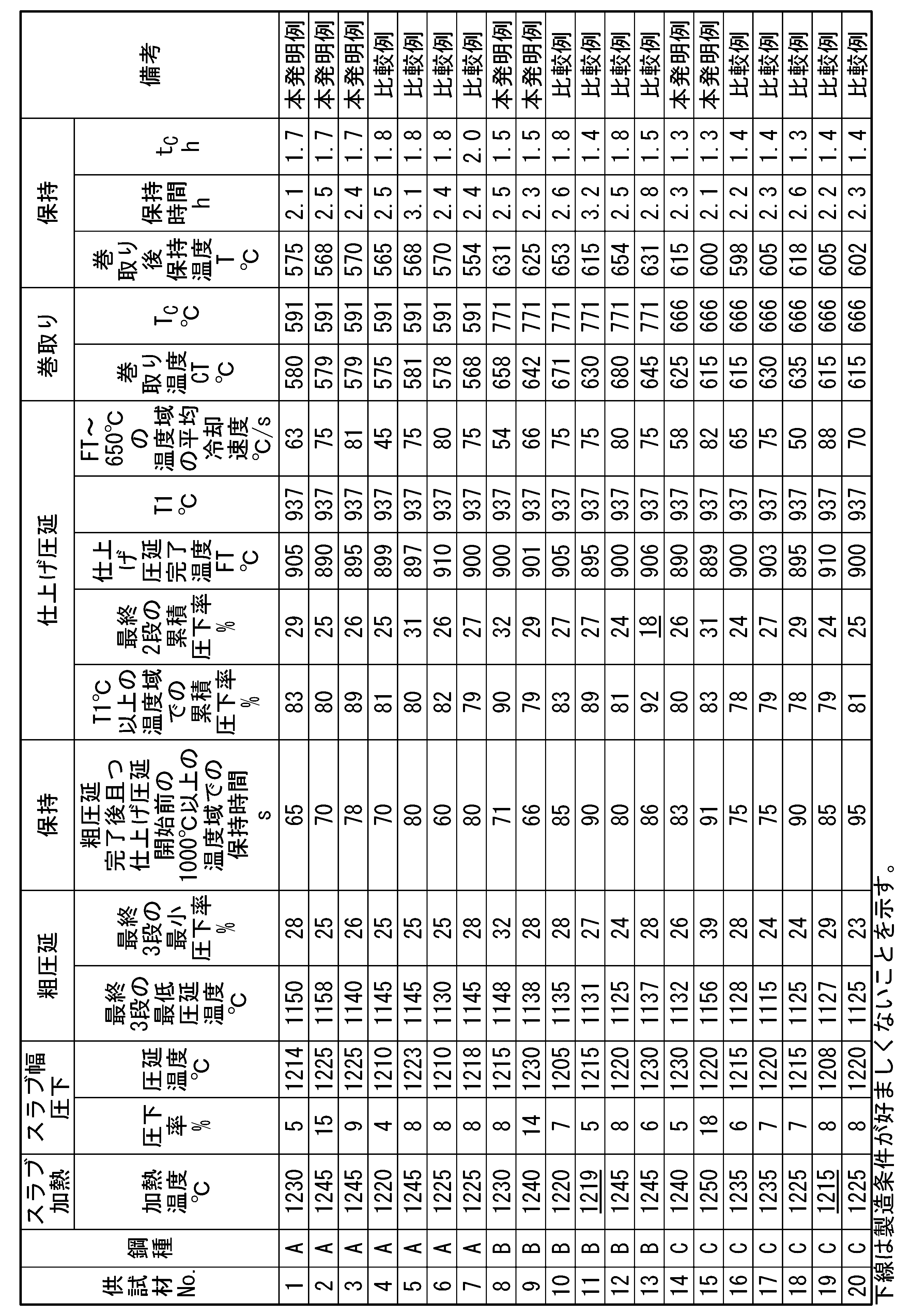


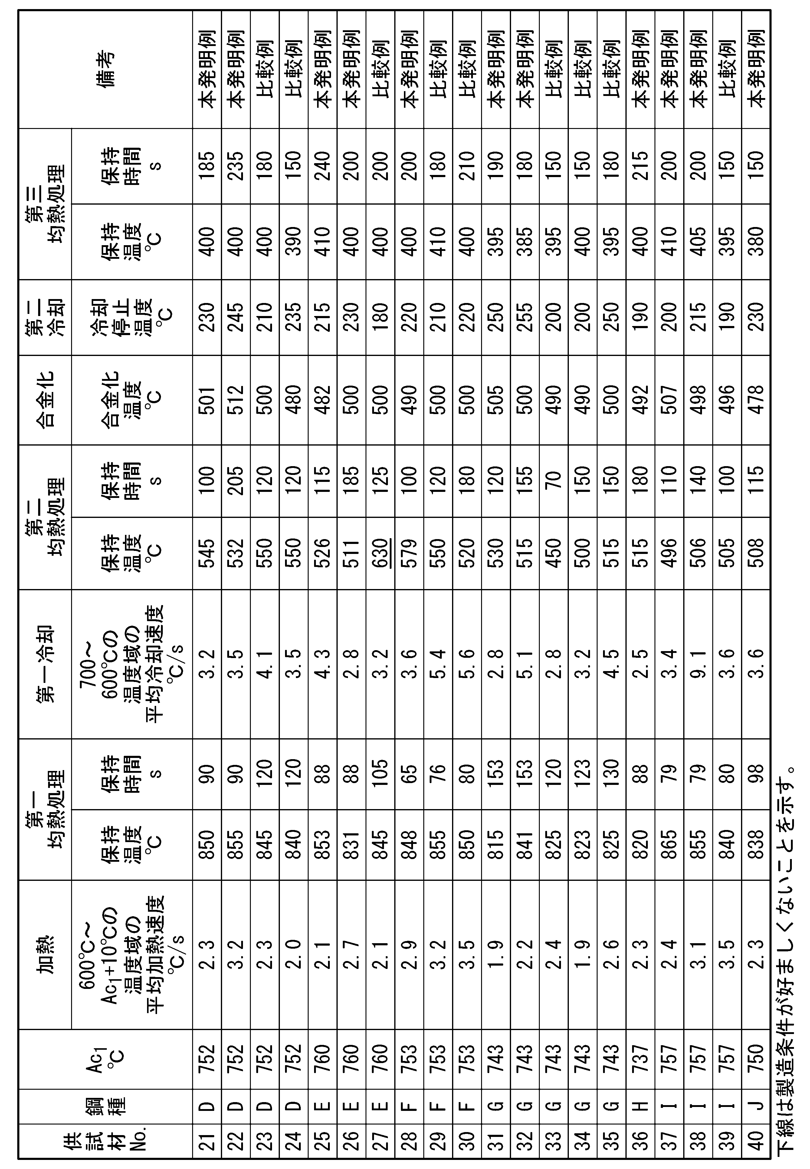


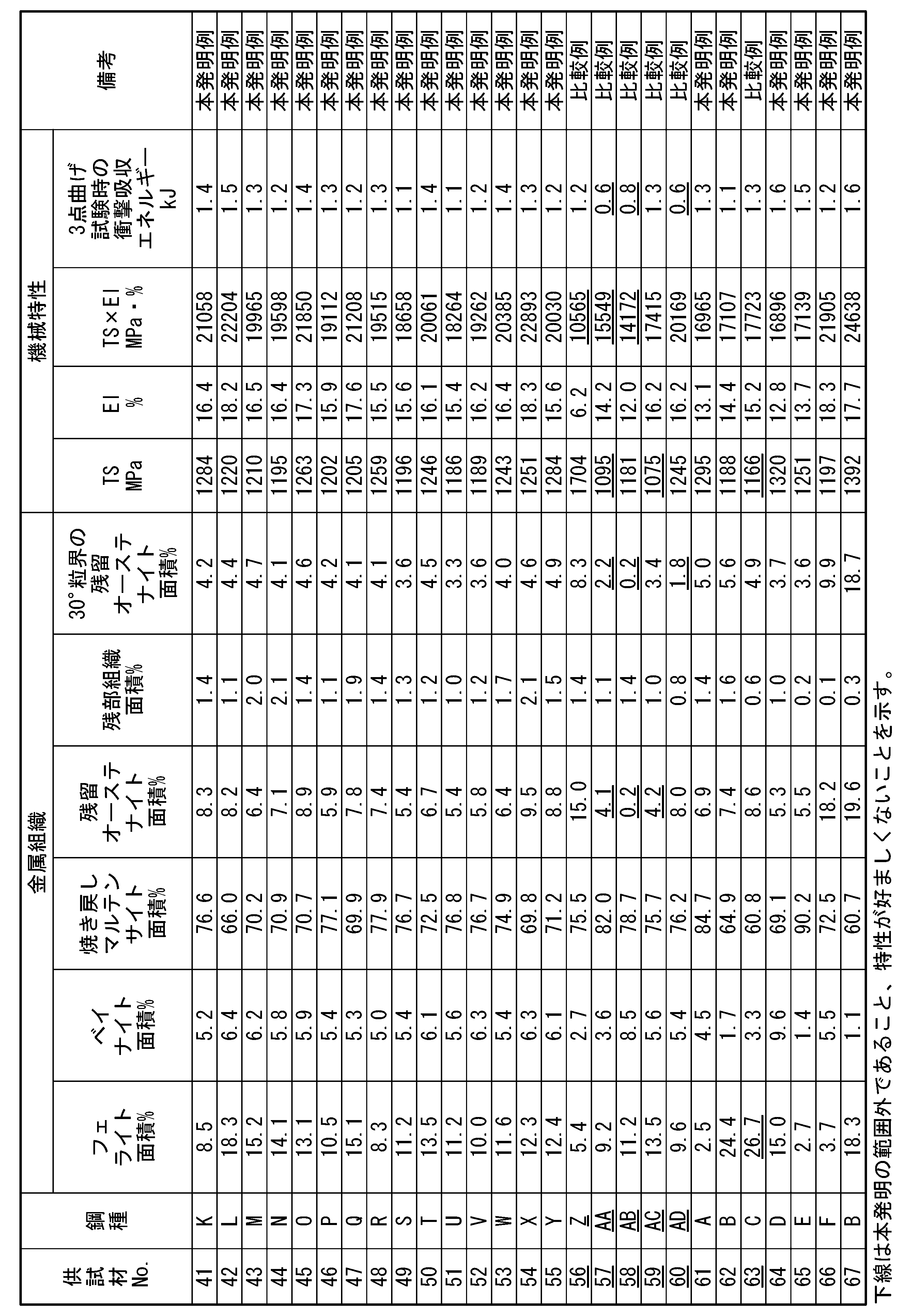
表4A~表4Cを見ると、本発明例に係る亜鉛めっき鋼板は、高い強度、並びに、優れた延性および耐衝撃特性を有することが分かる。また、10%以上の圧下率でスラブ幅圧下を行った本発明例は、30°粒界の残留オーステナイト面積率が5.0%以上であり、1.7kJ以上の衝撃吸収エネルギーが得られたことが分かる。
一方、比較例に係る亜鉛めっき鋼板は、上記特性のうちいずれか1つ以上を有さないことが分かる。
一方、比較例に係る亜鉛めっき鋼板は、上記特性のうちいずれか1つ以上を有さないことが分かる。
本発明に係る上記態様によれば、高い強度、並びに、優れた延性および耐衝撃特性を有する亜鉛めっき鋼板を提供することができる。
Claims (2)
- 鋼板と、前記鋼板上に配された亜鉛めっき層とを備える亜鉛めっき鋼板であって、前記鋼板の化学組成が、質量%で、
C :0.150~0.350%、
Si:0.100~2.500%、
Mn:1.50~4.50%、
sol.Al:0.010~1.000%、
P :0.100%以下、
S :0.030%以下、
N :0.100%以下、
O :0.010%以下、
Ti:0~0.200%、
Nb:0~0.025%、
V :0~0.100%、
B :0~0.0100%、
Cu:0~2.00%、
Cr:0~2.00%、
Mo:0~1.00%、
Ni:0~2.00%、
Ca:0~0.0200%、
Mg:0~0.0200%、
REM:0~0.1000%、
Bi:0~0.0200%、
Zr、Co、ZnおよびWのうち1種または2種以上:合計で0~1.0000%、並びに
Sn:0~0.100%を含有し、
残部がFeおよび不純物からなり、
前記鋼板の表面から板厚の1/4位置における金属組織が、
面積%で、
フェライト:2.0~25.0%、
ベイナイト:10.0%以下、
焼き戻しマルテンサイト:60.0%超、93.0%以下、
残留オーステナイト:5.0%以上を含み、
30°粒界に接し、且つ、Mn濃度が平均Mn濃度の1.2倍以上であり、且つ、結晶粒径が0.3~2.0μmである前記残留オーステナイトの面積率が3.0%以上である、ことを特徴とする亜鉛めっき鋼板。 - 前記鋼板の前記化学組成が、質量%で、
Ti:0.001~0.200%、
Nb:0.001~0.025%、
V :0.001~0.100%、
B :0.0001~0.0100%、
Cu:0.01~2.00%、
Cr:0.01~2.00%、
Mo:0.001~1.00%、
Ni:0.01~2.00%、
Ca:0.0005~0.0200%、
Mg:0.0005~0.0200%、
REM:0.0005~0.1000%、
Bi:0.0005~0.0200%、
Zr、Co、ZnおよびWのうち1種または2種以上:合計で0.0005~1.0000%、並びに
Sn:0.0005~0.100%
からなる群のうち1種または2種以上を含有することを特徴とする請求項1に記載の亜鉛めっき鋼板。
Applications Claiming Priority (2)
| Application Number | Priority Date | Filing Date | Title |
|---|---|---|---|
| JP2021-191746 | 2021-11-26 | ||
| JP2021191746 | 2021-11-26 |
Publications (1)
| Publication Number | Publication Date |
|---|---|
| WO2023095870A1 true WO2023095870A1 (ja) | 2023-06-01 |
Family
ID=86539608
Family Applications (1)
| Application Number | Title | Priority Date | Filing Date |
|---|---|---|---|
| PCT/JP2022/043522 WO2023095870A1 (ja) | 2021-11-26 | 2022-11-25 | 亜鉛めっき鋼板 |
Country Status (1)
| Country | Link |
|---|---|
| WO (1) | WO2023095870A1 (ja) |
Citations (5)
| Publication number | Priority date | Publication date | Assignee | Title |
|---|---|---|---|---|
| JPH1068046A (ja) * | 1996-08-27 | 1998-03-10 | Kawasaki Steel Corp | 冷延−焼鈍後の深絞り性と耐リジング性とに優れる熱延鋼板 |
| WO2013051160A1 (ja) * | 2011-10-07 | 2013-04-11 | Jfeスチール株式会社 | 成形性および耐衝撃性に優れた高強度溶融亜鉛めっき鋼板およびその製造方法 |
| WO2016157896A1 (ja) * | 2015-04-01 | 2016-10-06 | Jfeスチール株式会社 | 熱延鋼板およびその製造方法 |
| JP2017525847A (ja) * | 2014-07-03 | 2017-09-07 | アルセロールミタル | 強度、成形性が改善された高強度被覆鋼板の製造方法および得られた鋼板 |
| WO2019187124A1 (ja) * | 2018-03-30 | 2019-10-03 | 日本製鉄株式会社 | 溶融亜鉛めっき鋼板及び合金化溶融亜鉛めっき鋼板 |
-
2022
- 2022-11-25 WO PCT/JP2022/043522 patent/WO2023095870A1/ja unknown
Patent Citations (5)
| Publication number | Priority date | Publication date | Assignee | Title |
|---|---|---|---|---|
| JPH1068046A (ja) * | 1996-08-27 | 1998-03-10 | Kawasaki Steel Corp | 冷延−焼鈍後の深絞り性と耐リジング性とに優れる熱延鋼板 |
| WO2013051160A1 (ja) * | 2011-10-07 | 2013-04-11 | Jfeスチール株式会社 | 成形性および耐衝撃性に優れた高強度溶融亜鉛めっき鋼板およびその製造方法 |
| JP2017525847A (ja) * | 2014-07-03 | 2017-09-07 | アルセロールミタル | 強度、成形性が改善された高強度被覆鋼板の製造方法および得られた鋼板 |
| WO2016157896A1 (ja) * | 2015-04-01 | 2016-10-06 | Jfeスチール株式会社 | 熱延鋼板およびその製造方法 |
| WO2019187124A1 (ja) * | 2018-03-30 | 2019-10-03 | 日本製鉄株式会社 | 溶融亜鉛めっき鋼板及び合金化溶融亜鉛めっき鋼板 |
Similar Documents
| Publication | Publication Date | Title |
|---|---|---|
| JP6264507B2 (ja) | 高強度亜鉛めっき鋼板及びその製造方法 | |
| EP2762600B1 (en) | Hot-dip galvanized steel sheet and process for producing same | |
| US8657969B2 (en) | High-strength galvanized steel sheet with excellent formability and method for manufacturing the same | |
| CN114502759B (zh) | 热轧钢板 | |
| JP6897882B2 (ja) | 熱延鋼板およびその製造方法 | |
| EP3875615A1 (en) | Steel sheet, member, and method for manufacturing same | |
| JP6787532B2 (ja) | 熱延鋼板およびその製造方法 | |
| WO2020179292A1 (ja) | 熱延鋼板 | |
| WO2020179295A1 (ja) | 熱延鋼板 | |
| CN113227415B (zh) | 钢板、构件和它们的制造方法 | |
| JP7160199B2 (ja) | 鋼板 | |
| US20240052466A1 (en) | Steel sheet, member, and methods for manufacturing the same | |
| CN115768915A (zh) | 镀锌钢板、构件和它们的制造方法 | |
| JP7348574B2 (ja) | 熱延鋼板 | |
| JP7348573B2 (ja) | 熱延鋼板 | |
| JP7260825B2 (ja) | 熱延鋼板 | |
| WO2023095870A1 (ja) | 亜鉛めっき鋼板 | |
| JP7440804B2 (ja) | 熱間圧延鋼板 | |
| WO2023068369A1 (ja) | 鋼板 | |
| WO2023068368A1 (ja) | 鋼板 | |
| WO2023095866A1 (ja) | 熱延鋼板 | |
| WO2023189174A1 (ja) | ホットスタンプ成形体 | |
| WO2023095920A1 (ja) | 鋼部材及び鋼板 | |
| WO2023189183A1 (ja) | ホットスタンプ成形体 | |
| EP4130305A1 (en) | Steel sheet and method for producing same |
Legal Events
| Date | Code | Title | Description |
|---|---|---|---|
| 121 | Ep: the epo has been informed by wipo that ep was designated in this application |
Ref document number: 22898652 Country of ref document: EP Kind code of ref document: A1 |