WO2023095761A1 - ガラス振動板、振動子付きガラス振動板及び車両用振動板 - Google Patents
ガラス振動板、振動子付きガラス振動板及び車両用振動板 Download PDFInfo
- Publication number
- WO2023095761A1 WO2023095761A1 PCT/JP2022/043074 JP2022043074W WO2023095761A1 WO 2023095761 A1 WO2023095761 A1 WO 2023095761A1 JP 2022043074 W JP2022043074 W JP 2022043074W WO 2023095761 A1 WO2023095761 A1 WO 2023095761A1
- Authority
- WO
- WIPO (PCT)
- Prior art keywords
- glass
- vibrator
- plate structure
- glass plate
- mount
- Prior art date
- Legal status (The legal status is an assumption and is not a legal conclusion. Google has not performed a legal analysis and makes no representation as to the accuracy of the status listed.)
- Ceased
Links
Images















Classifications
-
- B—PERFORMING OPERATIONS; TRANSPORTING
- B60—VEHICLES IN GENERAL
- B60J—WINDOWS, WINDSCREENS, NON-FIXED ROOFS, DOORS, OR SIMILAR DEVICES FOR VEHICLES; REMOVABLE EXTERNAL PROTECTIVE COVERINGS SPECIALLY ADAPTED FOR VEHICLES
- B60J1/00—Windows; Windscreens; Accessories therefor
-
- B—PERFORMING OPERATIONS; TRANSPORTING
- B60—VEHICLES IN GENERAL
- B60J—WINDOWS, WINDSCREENS, NON-FIXED ROOFS, DOORS, OR SIMILAR DEVICES FOR VEHICLES; REMOVABLE EXTERNAL PROTECTIVE COVERINGS SPECIALLY ADAPTED FOR VEHICLES
- B60J1/00—Windows; Windscreens; Accessories therefor
- B60J1/08—Windows; Windscreens; Accessories therefor arranged at vehicle sides
- B60J1/12—Windows; Windscreens; Accessories therefor arranged at vehicle sides adjustable
- B60J1/16—Windows; Windscreens; Accessories therefor arranged at vehicle sides adjustable slidable
- B60J1/17—Windows; Windscreens; Accessories therefor arranged at vehicle sides adjustable slidable vertically
-
- H—ELECTRICITY
- H04—ELECTRIC COMMUNICATION TECHNIQUE
- H04R—LOUDSPEAKERS, MICROPHONES, GRAMOPHONE PICK-UPS OR LIKE ACOUSTIC ELECTROMECHANICAL TRANSDUCERS; ELECTRIC HEARING AIDS; PUBLIC ADDRESS SYSTEMS
- H04R1/00—Details of transducers, loudspeakers or microphones
- H04R1/02—Casings; Cabinets ; Supports therefor; Mountings therein
-
- H—ELECTRICITY
- H04—ELECTRIC COMMUNICATION TECHNIQUE
- H04R—LOUDSPEAKERS, MICROPHONES, GRAMOPHONE PICK-UPS OR LIKE ACOUSTIC ELECTROMECHANICAL TRANSDUCERS; ELECTRIC HEARING AIDS; PUBLIC ADDRESS SYSTEMS
- H04R7/00—Diaphragms for electromechanical transducers; Cones
- H04R7/02—Diaphragms for electromechanical transducers; Cones characterised by the construction
-
- H—ELECTRICITY
- H04—ELECTRIC COMMUNICATION TECHNIQUE
- H04R—LOUDSPEAKERS, MICROPHONES, GRAMOPHONE PICK-UPS OR LIKE ACOUSTIC ELECTROMECHANICAL TRANSDUCERS; ELECTRIC HEARING AIDS; PUBLIC ADDRESS SYSTEMS
- H04R7/00—Diaphragms for electromechanical transducers; Cones
- H04R7/02—Diaphragms for electromechanical transducers; Cones characterised by the construction
- H04R7/04—Plane diaphragms
Definitions
- the present invention relates to a glass diaphragm, a vibrator-equipped glass diaphragm, and a vehicle diaphragm.
- a desired sound can be obtained by vibrating an electronic device member, a vehicle window member, or an interior member of transportation machinery such as a vehicle with an exciter (vibrator, actuator).
- an exciter vibrator, actuator
- a technique for vibrating an openable door panel using such an exciter is applied.
- Patent Document 1 discloses an example in which a structure in which a plurality of exciters that electrically generate vibration are attached to the surface of a glass plate is incorporated into a door interior material. Further, in Patent Document 2, the vibration from the vibrator is transmitted to the vibration plate (glass substrate) via the vibration transmission part, one end of which is connected to an exciter. A configuration is disclosed in which a rod holding member is adhesively fixed to the surface of a glass substrate.
- an exciter hereinafter referred to as a vibrator
- the opening and closing of the door especially the impact caused by closing the door, may cause the vibration between the glass surface and the vibrator.
- a large stress tensile stress
- the vibrator is misaligned with respect to the glass surface, which causes problems such as deterioration of sound reproduction quality and the vibrator falling off the glass surface.
- the present invention provides a glass diaphragm, a vibrator-equipped glass diaphragm, and a vehicle vibration plate, which can suppress displacement and dropout of the vibrator even when a strong impact is applied to the glass diaphragm and can always hold the vibrator stably.
- the purpose is to provide a board.
- the present invention consists of the following configurations.
- a glass plate structure having a first main surface, a second main surface, and an end surface connecting the first main surface and the second main surface; a mounting portion fixed to a portion of the first main surface and a portion of the second main surface, respectively, and having a continuous structure including a portion facing the end surface; and a vibrator attachment portion to which a vibrator for vibrating the glass plate structure is attached to the mount portion.
- a vibrator-equipped glass diaphragm comprising the glass diaphragm according to (1) and a vibrator fixed to the vibrator mounting portion.
- a vehicle diaphragm wherein the vibrator-equipped glass diaphragm according to (2) is used for a vehicle window glass.
- the present invention even if a strong impact is applied to the glass diaphragm, it is possible to suppress the displacement and dropout of the vibrator, and to always hold the vibrator stably.
- FIG. 1 is a schematic plan view of a vibrator-equipped glass diaphragm.
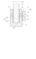
- FIG. 2 is a schematic cross-sectional view of the vibrator-equipped glass diaphragm shown in FIG. 1 taken along line II-II.
- FIG. 3A is an explanatory diagram showing how stress is generated when an impact is applied to the vibrator-equipped glass diaphragm.
- FIG. 3B is an explanatory diagram showing how stress is generated when an impact is applied to the vibrator-equipped glass diaphragm.
- FIG. 4A is a schematic cross-sectional view of a vibrator-equipped glass diaphragm, showing a modification in which the mount portion is joined to the glass plate structure.
- FIG. 4B is a schematic cross-sectional view of the vibrator-equipped glass diaphragm, showing a modification in which the mount portion is joined to the glass plate structure.
- FIG. 4C is a schematic cross-sectional view of the vibrator-equipped glass diaphragm, showing a modification in which the mount portion is joined to the glass plate structure.
- FIG. 4D is a schematic cross-sectional view of the vibrator-equipped glass diaphragm, showing a modification in which the mount portion is joined to the glass plate structure.
- FIG. 5 is a partial plan view of the vibrator-equipped glass diaphragm when the main part of FIG. 4C is viewed from the vibrator side.
- FIG. 5 is a partial plan view of the vibrator-equipped glass diaphragm when the main part of FIG. 4C is viewed from the vibrator side.
- FIG. 6A is a schematic cross-sectional view of a vibrator-equipped glass diaphragm, showing an arrangement example of a vibrator on a mount.
- FIG. 6B is a schematic cross-sectional view of a vibrator-equipped glass diaphragm, showing an arrangement example of a vibrator on a mount.
- FIG. 6C is a schematic cross-sectional view of a vibrator-equipped glass diaphragm, showing an arrangement example of the vibrator on the mount.
- FIG. 6D is a schematic cross-sectional view of a vibrator-equipped glass diaphragm, showing an arrangement example of the vibrator on the mount.
- FIG. 6A is a schematic cross-sectional view of a vibrator-equipped glass diaphragm, showing an arrangement example of a vibrator on a mount.
- FIG. 6B is a schematic cross-sectional view of a vibrator-equipped glass diaphragm, showing an arrangement example of a vibrator on a mount.
- FIG. 7A is a schematic cross-sectional view showing a configuration in which a vibrator is provided in a concave portion formed in a mount portion.
- FIG. 7B is a schematic cross-sectional view showing a configuration in which a vibrator is provided on a convex portion formed on the mount portion.
- FIG. 7C is a schematic cross-sectional view showing a configuration in which a vibrator is provided in a vibrator mounting portion including concave portions and convex portions formed in a mount portion.
- FIG. 8A is a schematic cross-sectional view showing the configuration of a vibrator mounting portion in which a vibrator is attached to a mount portion by screw connection.
- FIG. 8A is a schematic cross-sectional view showing the configuration of a vibrator mounting portion in which a vibrator is attached to a mount portion by screw connection.
- FIG. 8B is a schematic cross-sectional view showing the configuration of a vibrator mounting portion in which the vibrator is attached to the mount portion by screw connection.
- FIG. 9 is a schematic cross-sectional view showing another form of fixing the vibrator to the mount.
- FIG. 10 is a schematic cross-sectional view showing a state in which signal lines for driving the vibrator are accommodated in through holes formed in the mount section.
- FIG. 11 is a schematic cross-sectional view showing another form of fixing the vibrator to the mount.
- FIG. 12A is a schematic cross-sectional view showing the configuration of a mount section configured with a plurality of members.
- FIG. 12B is a schematic cross-sectional view showing another configuration of the mount section configured with a plurality of members.
- FIG. 12C is a schematic cross-sectional view showing another configuration of the mount section configured with a plurality of members.
- FIG. 12D is a schematic cross-sectional view showing another configuration of the mount section configured with a plurality of members.
- FIG. 13A is a schematic cross-sectional view showing a state in which a plurality of members forming a mount section are combined with each other in a spigot structure.
- FIG. 13B is a schematic cross-sectional view of a mount portion in which the recesses and protrusions shown in FIG. 13A have different shapes.
- 14A and 14B are schematic cross-sectional views showing the configuration of a mount portion having projecting pieces with different projecting heights.
- FIG. 15 is a schematic cross-sectional view showing the configuration of a mount formed by covering one end of the glass plate structure with a fiber composite material.
- FIG. 16A is a schematic plan view illustrating a glass plate structure on which mounts are arranged;
- FIG. 16B is a schematic plan view illustrating a glass plate structure on which mounts are arranged;
- FIG. 16C is a schematic plan view illustrating a glass plate structure on which mounts are arranged;
- FIG. 16D is a schematic plan view illustrating a glass plate structure on which mounts are arranged;
- FIG. 17 is a schematic cross-sectional view showing the configuration when the mount section has external threads.
- FIG. 18 is a schematic cross-sectional view showing a configuration in which the mount section has a plurality of external threads.
- FIG. 19 is a schematic plan view of a vibrator-equipped glass diaphragm according to Modification 1.
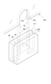
- FIG. 20 is an exploded perspective view of the glass plate structure and the mount shown in FIG. 19.
- FIG. 21 is a cross-sectional view taken along line XXI-XXI shown in FIG. 19.
- FIG. 22 is a cross-sectional view taken along line XXII-XXII shown in FIG. 19.
- FIG. 23 is a schematic plan view of a vibrator-equipped glass diaphragm according to Modification 2.
- FIG. 24 is an exploded perspective view of the glass plate structure and the mount shown in FIG. 23.
- FIG. 25 is a cross-sectional view taken along line XXV--XXV shown in FIG.
- FIG. 26 is a schematic cross-sectional view of a vibrator-equipped glass diaphragm in which the glass plate structure is laminated glass.
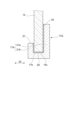
- FIG. 27 is a schematic cross-sectional view showing a conventional glass diaphra
- FIG. 1 is a schematic plan view of a vibrator-equipped glass diaphragm 100.
- FIG. A vibrator-equipped glass diaphragm 100 includes a glass diaphragm 11 and a vibrator 13 that generates vibration.
- the glass diaphragm 11 has a glass plate structure 15 and a mount portion 17 for fixing the vibrator 13 to the glass plate structure 15 .
- This vibrator-equipped glass diaphragm 100 vibrates the glass diaphragm 11 by driving the vibrator 13 to generate a desired sound.
- the vibrator 13 is a vibrating device that uses an object in contact with the vibrator body as a diaphragm and generates sound from the diaphragm.
- a known actuator such as an exciter can be used as the vibrator 13 .
- the vibrator-equipped glass diaphragm 100 when the vibrator-equipped glass diaphragm 100 is provided as a side window of a vehicle, the vibrator 13 is arranged on the connection portion 19 side with the lifting mechanism (not shown) below the belt line BL. Thereby, the sound generated from the glass plate structure 15 can be supplied into the passenger compartment.
- the application of the vibrator-equipped glass diaphragm 100 is not limited to this.
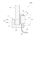
- FIG. 2 is a schematic cross-sectional view of the glass diaphragm 100 with vibrator shown in FIG. 1 taken along line II-II.
- the glass plate structure 15 has a first principal surface 15a, a second principal surface 15b, and an end surface 15c connecting the first principal surface 15a and the second principal surface 15b.
- the glass plate structure 15 is exemplified as a single glass plate (single plate glass), but other forms such as laminated glass may be used.
- the mounting portion 17 of this configuration includes a sandwiching portion 17a having a pair of projecting pieces 21a and 21b facing each other in a side view of the glass plate structure 15, and a portion facing the end surface 15c of the glass plate structure 15. It has a continuous structure including The inner surface of the protruding piece 21a is fixed to a portion of the first main surface 15a of the glass plate structure 15, and the inner surface of the protruding piece 21b is fixed to a portion of the second main surface 15b of the glass plate structure 15. be done.
- the end surface 15c of the glass plate structure 15 faces the bottom surface 17b between the pair of projecting pieces 21a and 21b.
- the mount portion 17 has at least one of the thickness from the first main surface 15a of the glass plate structure 15 and the thickness from the second main surface 15b of the glass plate structure 15, that is, the thickness of the glass plate structure 15. At least one of the thickness of the projecting piece 21a from the first main surface 15a and the thickness of the projecting piece 21b from the second main surface 15b of the glass plate structure 15 is preferably 30 mm or less, more preferably 25 mm or less. , 20 mm or less. As a result, it is possible to achieve a thin structure, reduce problems such as contact with external members, and easily realize space saving of the vibrator-equipped glass diaphragm 100 .
- the mount portion 17 is provided with a vibrator mounting portion 23 for mounting the vibrator 13 for vibrating the glass plate structure 15 .
- the vibrator mounting portion 23 shown here is preferably formed at a position overlapping at least a portion of the mount portion 17 facing the first main surface 15a in a plan view of the first main surface 15a of the glass plate structure 15. , is more preferably formed in a position overlapping all of them. In this case, the vibration from vibrator 13 can be transmitted to glass plate structure 15 with high efficiency.
- a first adhesive layer 25 is provided on at least a portion between the inner surface of the projecting piece 21 a of the mount portion 17 and the first main surface 15 a of the glass plate structure 15 .
- a second adhesive layer 27 is provided at least partially between the inner surface of the projecting piece 21 b and the second main surface 15 b of the glass plate structure 15 . The first adhesive layer 25 and the second adhesive layer 27 fix the glass plate structure 15 while sandwiching it between the sandwiching portions 17 a of the mount portion 17 .
- the mount portion 17 is formed in a U shape when the glass plate structure 15 is viewed from the side. Therefore, even if an impact is applied to the glass diaphragm 11 in the plate thickness direction of the glass plate structure 15, the tensile stress applied to the first adhesive layer 25 and the second adhesive layer 27 is relaxed.
- FIGS. 3A and 3B are explanatory diagrams showing how stress is generated when an impact is applied to the vibrator-equipped glass diaphragm 100.
- FIG. In the following description, the same parts or members are given the same reference numerals to simplify or omit the description.
- a large impact may occur when the door is opened and closed, especially when the door is closed.
- the tensile stress applied to the first adhesive layer 25 is reduced, and the tensile stress does not act on the second adhesive layer 27 . Therefore, even if the vibrator-equipped glass diaphragm 100 is subjected to an impact, the first adhesive layer 25 and the second adhesive layer 27 are less likely to be damaged such as cracks, and the mount portion 17 stably holds the vibrator 13. It becomes easier to adhere to the glass plate structure 15 .
- the above-described effect can be achieved either when an impact is applied to the vibrator-equipped glass diaphragm 100 when the door is opened, or when an impact is applied when the door is closed in a configuration in which the vibrator 13 is arranged on the opposite side of FIG. 3A.
- a similar effect can be obtained for As shown in FIG. 3B , when an impact in the direction of arrow D2 is applied to vibrator-equipped glass diaphragm 100 , compressive force Fc is generated from vibrator 13 toward mount portion 17 .
- This compressive force Fc is composed of a force fa pressing the vibrator 13 side projecting piece 21a of the mount portion 17 against the glass plate structure 15 via the first adhesive layer 25, and a projection formed integrally with the projecting piece 21a.
- the piece 21b becomes a force fb that pulls the glass plate structure 15 in the direction of the arrow D2 through the second adhesive layer 27 . Therefore, the tensile stress applied to the second adhesive layer 27 only needs to correspond to the force fb obtained by subtracting the force fa from the compressive force Fc. In addition, only compressive stress is applied to the first adhesive layer 25, which makes it difficult for the adhesive layer to break.
- the mount part 17 can be made of one or a plurality of materials selected from, for example, metal materials such as aluminum or aluminum alloys, titanium or titanium alloys, stainless steel, ceramics, glass, stone materials, wood, resin materials, fiber composite materials, and the like.
- resin materials include acrylic resins such as polymethyl methacrylate resin (PMMA), polycarbonate (PC), polyvinyl chloride (PVC), urethane, polybutylene terephthalate (PBT), nylon 66, polyphenylene sulfide (PPS), Polypropylene (PP), ABS resin, or the like can be used, and a structure having excellent moldability can be obtained.
- a fiber-reinforced plastic obtained by combining the above material with glass fiber, carbon fiber, or the like may be used. By using the above materials, it is possible to suppress the occurrence of cracks or the like in the mount portion 17 and obtain sufficient connection strength.
- fiber composite materials include reinforced fiber composite materials in which fiber materials such as aramid fibers and carbon fibers are arranged in a mesh and integrally molded with a resin material. By using a fiber composite material, it is possible to reduce the weight while maintaining the strength of the mount. In addition, fiber composite materials containing mesh-like fibrous materials have unique vibration transmission properties that reduce noise from the mount and provide good sound reproduction quality.
- the mount portion 17 preferably has a Young's modulus at 25° C. of 1 ⁇ 10 8 Pa or more, more preferably 50 ⁇ 10 8 Pa or more, and even more preferably 100 ⁇ 10 8 Pa or more. A higher Young's modulus of the mount portion 17 is more preferable, but the upper limit is preferably 1 ⁇ 10 12 Pa or less, for example.
- the longitudinal wave sound velocity value in the glass plate thickness direction in the mount portion 17 is preferably 2.0 ⁇ 10 3 m / s or more because the higher the reproducibility of the high frequency sound range when vibrating is improved, and 3.0 ⁇ 10 3 m/s or more is more preferable, and 4.0 ⁇ 10 3 m/s or more is even more preferable.
- the longitudinal wave sound velocity value is preferably 7.0 ⁇ 10 3 m/s or less.
- the longitudinal wave sound velocity value refers to the velocity at which the longitudinal wave propagates in the diaphragm.
- the longitudinal wave sound velocity value and Young's modulus can be measured by the ultrasonic pulse method or the like described in Japanese Industrial Standards (JIS R 1602-1995).
- Materials for the first adhesive layer 25 and the second adhesive layer 27 include a thermosetting adhesive, a photo-curable adhesive, a moisture-curable adhesive, an anaerobic-curable adhesive, a thermoplastic adhesive, and a two-liquid mixture.
- Various adhesives such as curable adhesives can be used.
- thermosetting adhesives the crosslink density can be increased by adjusting the types and ratios of the materials put into the adhesive, and the heat resistance, chemical resistance, and moisture resistance after curing can be improved.
- the bonding work time can be shortened because it can be instantly bonded by irradiating ultraviolet rays.
- the material of the first adhesive layer 25 and the second adhesive layer 27 may not be an adhesive, but may be a group of materials that adhere by thermoplasticizing a film material, such as polyvinyl butyral resin (PVB). , ethylene-vinyl acetate copolymer resin (EVA), urethane, silicone, and the like.
- PVB polyvinyl butyral resin
- EVA ethylene-vinyl acetate copolymer resin
- silicone silicone
- the materials for the first adhesive layer 25 and the second adhesive layer 27 are selected from the viewpoint of preventing cracking of the glass due to the difference in linear expansion during bonding with the glass in the operating temperature range (-40 ° C. to 90 ° C.). Those with low hardness are preferred. Therefore, the Young's modulus of the first adhesive layer 25 and the second adhesive layer 27 is preferably 0.01 MPa or more and 100 MPa or less.
- the thickness of the first adhesive layer 25 and the second adhesive layer 27 is preferably 1 ⁇ m or more, more preferably 20 ⁇ m or more, and even more preferably 50 ⁇ m or more. Also, the thickness of the first adhesive layer 25 and the second adhesive layer 27 is preferably 5 mm or less, more preferably 3 mm or less, and even more preferably 1.5 mm or less. When each adhesive layer is in the above range, sufficient bonding strength can be obtained while the mount portion 17 after bonding maintains parallelism with the main surface of the glass plate.
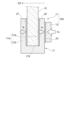
- FIG. 4A is a schematic cross-sectional view of a vibrator-equipped glass diaphragm 100A, showing a modification of the adhesive layer that bonds the mount portion 17 to the glass plate structure 15.
- FIG. A vibrator-equipped glass diaphragm 100A of this modification includes an end surface 15c of a glass plate structure 15 and a bottom surface 17b of a sandwiching portion 17a of a mount portion 17 facing the end surface 15c (corresponding to the bottom surface of the U-shaped mount portion 17). and has a third adhesive layer 29 at least partly between them.
- the glass plate structure 15 is bonded to the mount portion 17 in the plate thickness direction Dt, and is also attached to the surface direction Df of the first main surface 15a (second main surface 15b) perpendicular to the plate thickness direction. It is adhered to the mount portion 17 .
- the adhesive layers Ad may contain spacers.
- the spacer is made of a material comprising at least one of resin, metal, wood, ceramics, glass, and stone, and is more preferably a soft material such as rubber or gel.
- the third adhesive layer 29 bonds the mount portion 17 in the surface direction Df of the glass plate structure 15, so that the bonding strength can be increased against the external force acting in the surface direction Df. Further, since three surfaces of the glass plate structure 15 are fixed to the mount portion 17, the displacement of the mount portion 17 within the plane of the first principal surface 15a (second principal surface 15b) is restrained. As a result, a stronger bonding form can be obtained between the mount portion 17 and the glass plate structure 15 .
- FIG. 4B to 4D are schematic cross-sectional views of vibrator-equipped glass diaphragms 100B to 100D, showing modifications in which the mount portion 17 is joined to the glass plate structure 15.
- FIG. A vibrator-equipped glass diaphragm 100B shown in FIG. 4B has a through hole 30 penetrating through the glass plate structure 15 in the plate thickness direction Dt, and the through hole 30 is filled with an adhesive layer.
- Other configurations are the same as those of the vibrator-equipped glass diaphragm 100A shown in FIG. 4A described above.
- the through hole 30 is formed in a region overlapping the mount portion 17 in the plate thickness direction Dt. It is preferable to dispose the through-hole 30 and the vibrator 13 at positions that do not overlap in the plate thickness direction Dt because the vibration from the vibrator 13 can be easily transmitted to the glass plate structure 15 with high efficiency. In some cases, at least part of the vibrator 13 overlaps the through hole 30 in the plate thickness direction Dt due to restrictions on the installation space. It is sufficient if the above can be secured. Moreover, although the shape of the through-hole 30 is circular in plan view of the glass plate structure 15, it is not limited thereto.
- the glass plate structure 15 and the mount portion 17 are joined by the adhesive layer Ad filled inside the through hole 30, so that the anchor effect of the adhesive layer Ad in the through hole 30 can be obtained. , the mutual bonding strength can be further enhanced.
- FIG. 5 is a partial plan view of the vibrator-equipped glass diaphragm when the essential part of FIG. 4C is viewed from the vibrator 13 side.
- the glass plate structure 15 and the mount portion 17 are joined to each other by inserting the rod-like member 34 through the through holes 30 and 32 and filling the inside of the mount portion 17 and the inside of the through hole 30 with an adhesive layer Ad.
- the rod-shaped member 34 may be a round bar or a fastening member such as a bolt or rivet.
- the mount portion 17 having a U-shaped cross section perpendicular to the plate surface of the glass plate structure 15 can be mounted.
- the rod-like member 34 provides an anchoring effect to prevent slipping. Thereby, the bonding strength between the glass plate structure 15 and the mount portion 17 can be further increased.
- a fastening portion 24 for fastening the vibrator 13 is provided at one end of the rod-shaped member 34, and the vibrator 13 is fixed to the fastening portion 24.
- the configuration is similar to that shown.
- the fastening portion 24 may be a connection mechanism such as a screw or an adhesive layer for connecting to the vibrator 13, and the joining form is not limited.
- the rod-shaped member 34 and the vibrator 13 are integrally fixed by the fastening portion 24 . Therefore, the handling of the rod-shaped member 34 and the vibrator 13 can be improved, and the work of inserting the rod-shaped member 34 into the through hole 30 and the work of attaching the vibrator 13 to the mount portion 17 can be performed together. The joining process of each member can be simplified. Moreover, the rod-shaped member 34 not only prevents the mount portion 17 from falling off from the glass plate structure 15, but also has the effect of transmitting the vibration from the vibrator 13 to the glass plate structure 15 with high efficiency.
- Example of vibrator arrangement> 6A to 6D are schematic sectional views of vibrator-equipped glass diaphragms 100E, 100F, 100G, and 100H, respectively, showing other examples of arrangement of the vibrator 13 on the mount.
- the above-described third adhesive layer 29 is omitted.
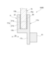
- a mounting portion 17A shown in FIG. 6A includes a sandwiching portion 17a having a pair of protruding pieces 21a and 21b (also referred to as glass-side protruding pieces) projecting from the bottom surface 17b (in the surface direction Df) facing each other, and a glass An anti-glass side protruding piece 17c extends in a direction (downward in FIG. 6A) opposite to the protruding direction of the side protruding pieces 21a and 21b.
- the mount portion 17A is formed in a small letter y shape (also referred to as a ⁇ shape) in a cross-sectional view (or side view) of the glass plate structure 15 .
- a glass plate structure 15 is sandwiched between the pair of glass-side projecting pieces 21a and 21b.
- a vibrator 13 is provided on the anti-glass side projecting piece 17c. As shown in FIG. 6A, the vibrator 13 is provided on the opposite side of the anti-glass-side protruding piece 17c to the glass plate structure 15 side with respect to the plate thickness direction Dt via a vibrator mounting portion (not shown). Alternatively, it may be provided on the opposite surface of the glass plate structure 15 side. If the vibrator 13 is provided only on the latter surface on the side of the glass plate structure 15, the thickness of the vibrator-equipped glass diaphragm can be reduced.
- the vibration from the vibrator 13 is evenly distributed to both the first main surface 15a and the second main surface 15b of the glass plate structure 15 from the pair of protruding pieces 21a and 21b. , the vibration is propagated isotropically and a homogeneous acoustic effect is obtained.
- the vibrator 13 may be arranged at a position straddling both the protruding piece 21a and the anti-glass side protruding piece 17c.
- a mounting portion 17B shown in FIG. 6B includes a sandwiching portion 17a having a pair of protruding pieces 21a and 21b (also referred to as glass-side protruding pieces) and a direction opposite to the protruding direction of the glass-side protruding pieces 21a and 21b (in FIG. 6B, and an anti-glass side protruding piece 17c extending downward).
- the anti-glass-side protruding piece 17c is provided at an intermediate position between the first main surface 15a and the second main surface 15b of the glass plate structure 15 in the plate thickness direction Dt. That is, the mount portion 17B is formed in the shape of a capital letter Y in a cross-sectional view (or side view) of the glass plate structure 15 .
- the anti-glass side protruding piece 17c has a through hole 36 penetrating in the plate thickness direction Dt.
- a shaft portion 38 b of a joint member 38 having a head portion 38 a and a shaft portion 38 b having a diameter smaller than that of the head portion 38 a and capable of being inserted into the through hole 36 is inserted into the through hole 36 .
- a male thread is formed at the tip of the shaft portion 38b, and by meshing with a female thread formed on the oscillator 13, the oscillator 13 may be fastened to the anti-glass side projecting piece 17c.
- an appropriate adhesive layer may be provided, or engaging portions for engaging with each other may be provided on both sides.
- the vibrator-equipped glass diaphragm 100F having this configuration, it is possible to suppress the protrusion of the vibrator 13 in the plate thickness direction Dt, and to obtain a sufficient space in the plate thickness direction Dt. As a result, it can be easily installed even in a narrow space such as the inside of a vehicle door, and the flexibility of installation can be improved.
- a third adhesive layer 29 may be provided between the bottom surface 17b on the base side of the glass-side projecting pieces 21a and 21b and the end surface 15c of the glass plate structure 15.
- a mounting portion 17C shown in FIG. 6C includes a sandwiching portion 17a having a pair of glass-side projecting pieces 21a and 21b projecting from the bottom surface 17b (in the surface direction Df) facing each other, and glass-side projecting pieces 21a and 21b. and a pair of anti-glass side protruding pieces 17c and 17d facing each other.
- the mount portion 17C is formed in an H shape when the glass plate structure 15 is viewed in cross section (or viewed from the side).
- the vibrator 13 is provided inside the mounting portion 17C sandwiched between the anti-glass side protruding piece 17c and the anti-glass side protruding piece 17d.
- the vibrator mounting portion (not shown) for receiving the vibrator 13 may be provided on the inner surface of either of the anti-glass side projecting pieces 17c and 17d.
- the vibration from the vibrator 13 is applied to both the first main surface 15a and the second main surface 15b of the glass plate structure 15, as in the case shown in FIG. 5A. Propagated isotropically, resulting in a homogenous sound effect. Since the vibrator 13 is arranged between the pair of protruding pieces 17c and 17d opposite to the glass side, the glass plate structure 15 does not have a portion protruding from the vibrator mounting portion when viewed from the side. As a result, protrusion from the glass plate structure 15 in the plate thickness direction Dt is suppressed, and the thickness of the vibrator-equipped glass diaphragm can be reduced.
- a mounting portion 17D shown in FIG. 6D includes a sandwiching portion 17a having a pair of glass-side protruding pieces 21a and 21b protruding (in the plane direction Df) from the bottom surface 17b described above, and the protruding directions of the glass-side protruding pieces 21a and 21b. has a base 17e extending in opposite directions.
- a vibrator 13 is provided on the base portion 17e of the mount portion 17D.
- a vibrator mounting portion (not shown) for receiving the vibrator 13 may be provided on either the surface of the base portion 17e facing the glass-side protruding piece 21a or the other surface of the base portion 17e facing the glass-side protruding piece 21b.
- the vibration from the vibrator 13 is applied to both the first main surface 15a and the second main surface 15b of the glass plate structure 15, as in the case shown in FIG. 6A. Propagated isotropically, resulting in a homogenous sound effect. Further, since the vibrator 13 is arranged on the thick base portion 17e, the vibration is transmitted more evenly. Note that the vibrator 13 may be arranged at a position straddling both the projecting piece 21a and the base portion 17e (or both the projecting piece 21b and the base portion 17e).
- FIG. 7A is a schematic cross-sectional view showing a configuration in which the vibrator 13 is provided in the concave portion 31 formed in the mount portion 17E.
- the vibrator mounting portion 23A of the mount portion 17E may include a concave portion (groove) 31 provided in the projecting piece 21a. The vibrator 13 is inserted into the recess 31 and attached to the mount portion 17E.
- At least a part of the vibrator mounting portion 23A has a recess 31, and the vibrator 13 is housed in this recess 31. Protrusion can be suppressed, and the thickness of the vibrator-equipped glass diaphragm can be reduced.
- FIG. 7B is a schematic cross-sectional view showing a configuration in which the vibrator 13 is provided on the convex portion 33 formed on the mount portion 17F.
- the vibrator mounting portion 23B of the mount portion 17F may include a convex portion 33 provided on the projecting piece 21a.
- the vibrator 13 is attached to the convex portion 33 .
- the vibration from the vibrator 13 is intensively propagated to the convex portion 33, and the vibration can be transmitted to the glass plate structure 15 efficiently.
- FIG. 7C is a schematic cross-sectional view showing a configuration in which the vibrator 13 is provided on the vibrator mounting portion 23C including the concave portion 31 and the convex portion 33 formed in the mount portion 17G.
- the vibrator mounting portion 23C of the mount portion 17G may be composed of a concave portion (groove) 31 and a convex portion 33 provided on the protruding piece 21a.
- this vibrator-equipped glass diaphragm 100K since the vibrator 13 has the protrusion 13a that engages with the recess 31, the protrusion 13a is inserted into the recess 31, and the vibrator 13 is attached to the mount 17G. Can be easily positioned to position.
- the vibrator mounting portions 23A, 23B, and 23C shown in FIGS. 7A to 7C may have a structure in which the vibrator 13 is joined to the mounting portions 17E, 17F, and 17G with an adhesive, and may be a plug-in type such as screw or taper fitting.
- a mechanical joining structure such as a connection, a caulking connection using a rivet or the like, a connection using a clamp, or the like may be used.
- FIGS. 8A and 8B are schematic cross-sectional views showing the configuration of a vibrator mounting portion in which the vibrator 13 is attached to the mount portion 17H by screw connection.
- a protruding piece 21a of the mount portion 17H is formed with a through hole 35 along the plate thickness direction Dt, and a female screw 37 is formed on the inner peripheral surface of the through hole 35.
- the vibrator 13 is formed to have a cylindrical portion, and a male thread 39 that meshes with the female thread 37 is formed on the outer peripheral surface of the cylinder.
- the vibrator 13 when the vibrator 13 is screwed to the through hole 35 of the mount portion 17H, the vibrator 13 having a thickness ts greater than the thickness tm of the protruding piece 21a in the plate thickness direction Dt is attached to the mount portion 17H. 17H is tightened and fixed.
- the mount portion 17H is reinforced by mechanical connection with the vibrator 13, and the bending rigidity of the whole is improved. Therefore, even if a large tensile stress occurs in the mount portion 17H due to an impact when the door is closed, for example, the mount portion 17H is less likely to deform.
- the vibrator 13 is shown in a cylindrical shape, but the cross section may have a T-shaped configuration or an L-shaped configuration. When the vibrator 13 has a T-shaped cross section, the outer edge of the vibrator 13 may have a concentric relationship with the outer edge of the cylinder in plan view of the glass plate structure 15 .
- Equation (1) the moment of inertia I of the projecting piece 21a of the mount portion 17H is expressed by Equation (1)
- Equation (2) the deflection (curvature radius ⁇ ) of the projecting piece 21a (21b) is expressed by Equation (2). be.
- the Young's modulus E and the geometrical moment of inertia I of the projecting piece 21a of the mount part 17H should be increased. .
- each of the above parameters is as follows.
- b width of the projecting piece 21a (see FIG. 1: width in the direction perpendicular to the surface direction Df and the plate thickness direction Dt)
- h thickness of projecting piece 21a (see FIG. 2: thickness in plate thickness direction Dt)
- M Bending moment generated in projecting piece 21a due to impact
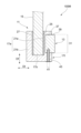
- FIG. 9 is a schematic cross-sectional view showing another form of fixing the vibrator 13 to the mount portion 17I.
- a circular concave portion 31 is formed in the projecting piece 21a of the mount portion 17I when viewed from the plate thickness direction Dt.
- a female thread 37 is formed on the side surface of the recess 31
- a male thread 39 is formed on the outer peripheral surface of the vibrator 13 .
- a through hole 41 is formed in the mount portion 17I so as to penetrate from the side surface of the recess 31 in the plane direction Df of the glass plate structure 15 .
- a set screw 43 is inserted into the through hole 41 .
- the set screw 43 fixes the vibrator 13 in the recess 31 by restricting loosening of the screw between the vibrator 13 and the mount portion 17I. With this configuration, it is possible to further suppress positional displacement and falling off of the vibrator 13 from the mount portion 17I.
- the through hole 41 may be a threaded hole having a female thread formed on the inner peripheral surface, or may be a circular hole having a constant diameter when viewed from the axial direction of the through hole 41, or a tapered hole whose diameter gradually decreases toward the recess 31 side. A hole having a shaped inner peripheral surface may also be used.
- the through hole 41 can be used for various purposes depending on the purpose.
- the set screw 43 is preferably a low head screw (slim head screw) having a flat and thin head.
- the set screw 43 may be a countersunk head screw or a truss head screw.
- the set screw 43 is a low-head screw, it is not necessary to taper the through hole 41 as in the case of a countersunk head screw, which improves workability. It can be improved and is desirable. Also, when the set screw 43 is a low-head screw, the screw head is prevented from protruding from the plate surface as in the case of a truss machine screw, and the surface after installation becomes nearly flush. This also applies to tapping screws 47 (FIG. 11) and fixing screws 51 (FIGS. 12A to 12D) described below.
- FIG. 10 is a schematic cross-sectional view showing a state in which a signal line 45 for driving the vibrator 13 is accommodated in a through hole 41 formed in the mount portion 17J.
- the through hole 41 may be used not only for fixing the vibrator 13 to the recess 31 but also as a hole for drawing out the signal line 45 or the like connected to the vibrator 13 to the outside of the mount portion 17J.
- this vibrator-equipped glass diaphragm 100N since the signal line 45 is housed in the through hole 41 in actual use, space can be saved, and (at least part of) the signal line 45 and external members It is possible to prevent damage to the signal line 45 due to the surrounding environment or the like.
- FIG. 11 is a schematic cross-sectional view showing another form of fixing the vibrator 13 to the mount portion 17K.
- the vibrator-equipped glass diaphragm 100P fixes the vibrator 13, which is screwed to the concave portion 31 of the projecting piece 21a of the mount portion 17K, by screwing the tapping screw 47 thereinto. According to this, it is not necessary to provide a through hole in advance in the mount portion 17K, and the vibrator 13 can be fixed by the tapping screw 47 as required depending on the usage conditions and the like.
- FIG. 12A is a schematic cross-sectional view showing a mount portion 17L configured with a plurality of members, more specifically, configured by assembling a plurality of members.
- the mount portion 17L faces the projecting piece 21a facing the first main surface 15a of the glass plate structure 15, the projecting piece 21b facing the second main surface 15b, and the end surface 15c. and a base 17e.
- the protruding piece 21b and the base portion 17e are integrally formed, and have an L shape when viewed in cross section (or when viewed from the side).
- the protruding piece 21a is configured separately from the protruding piece 21b and the base 17e, and one end of the protruding piece 21a is arranged on a surface extending along the bottom surface 17b of the base 17e.
- the base portion 17e and the projecting piece 21a may be screwed in the surface direction Df by a fixing screw 51, or may be joined only by an adhesive such as the first adhesive layer 25 and the second adhesive layer 27. Both adhesives may be used. As a result, the pair of protruding pieces 21a and 21b face each other to form the pinching portion 17a.
- the mount portion 17L shown here has the same concave portion 31 as the mount portion 17I shown in FIG. Also, the protruding piece 21a may be mechanically joined to the base 17e by means other than screwing.
- the mounting portion 17L is composed of a plurality of members, the width dimension of the sandwiching portion 17a can be freely adjusted, thereby improving the versatility. is easier, and workability is improved.
- the mounting portion 17L can be easily disassembled, and the mounting portion 17L can be easily removed from the glass plate structure 15.
- FIG. By including the L-shaped member, the number of mechanical joints required for a plurality of members can be reduced, and in this respect also workability can be improved.
- FIG. 12B, 12C, and 12D are schematic cross-sectional views showing the configuration of another mount portion configured with a plurality of members.
- the mounting portion 17M shown in FIG. 12B is formed such that the projecting piece 21a extends so as to cover the base portion 17e in plan view of the glass plate structure 15, and the fixing screw 51 extends from the projecting piece 21a in the plate thickness direction Dt. It is screwed toward the base 17e.
- a mounting portion 17N shown in FIG. 12C is formed by integrally forming a protruding piece 21a and a base portion 17e, and in a plan view of the glass plate structure 15, the protruding piece 21b extends so as to cover the base portion 17e.
- a fixing screw 51 is screwed from the projecting piece 21b toward the base portion 17e in the plate thickness direction Dt.
- a mount portion 17O shown in FIG. 12D is integrally formed with a projecting piece 21a and a base portion 17e, and one end of the projecting piece 21b is arranged on a surface extending along the bottom surface 17b of the base portion 17e.
- a fixing screw 51 is screwed from the base portion 17e toward the projecting piece 21b in the surface direction Df.
- mount portions 17M, 17N, and 17O also improve versatility and workability, and facilitate disassembly of the mount portions, similarly to the mount portion 17L shown in FIG. 12A.
- FIG. 13A is a schematic cross-sectional view showing a state in which a plurality of members forming the mount portion 17P1 are combined with each other in a spigot structure.
- a mounting portion 17P1 shown in FIG. 13A is obtained by omitting the fixing screw 51 from the configuration of the mounting portion 17L shown in FIG. 12A, and combines the protruding piece 21a and the base portion 17e with a fitting structure.
- a groove-shaped concave portion 81 is provided in the base portion 17e of the mount portion 17P1 , and a convex portion 83 that engages with the concave portion 81 is provided in the protruding piece 21a.
- the width dimension of the convex portion 83 gradually increases toward the tip on the side of the base portion 17e.
- the concave portion 81 has a shape in which the groove width widens toward the groove bottom so as to correspond to the width dimension of the convex portion 83 .
- the convex portion 83 and the concave portion 81 are formed by extending linearly along the depth direction (perpendicular to the paper surface) of FIG. 13A on the bottom surface 17b of the base portion 17e. That is, the convex portion 83 and the concave portion 81 are combined so as to engage with each other and slide freely in the longitudinal direction.
- the positioning accuracy and joint strength of both are enhanced.
- the base portion 17e and the projecting piece 21a can be joined together by sliding them to each other, thereby improving the workability of the assembly.
- the concave portion 81 and the convex portion 83 may have a configuration in which the convex portion is provided on the base portion 17e and the concave portion is provided on the protruding piece 21a. Also in this case, positioning accuracy, joint strength, and assembling workability can be improved in the same manner as described above.
- the protruding piece 21a is prevented from being displaced by the friction between the concave portion 81 and the convex portion 83, and is fixed to the glass plate structure 15 by the first adhesive layer 25, so that the protruding piece 21a is reliably prevented from coming off from the base portion 17e.
- the interface between the concave portion 81 and the convex portion 83 may be further fixed via an adhesive layer.
- the adhesive layer for example, the same material as the first adhesive layer 25 can be used.
- FIG. 13B is a schematic cross-sectional view of the mount portion 17P2 having a cross-sectional shape different from that of the concave portion 81 and the convex portion 83 shown in FIG. 13A.
- the protruding piece 21a is provided with a column portion 85 projecting from the tip of the base portion 17e side to the base portion 17e side, and a flange portion 87 provided at the tip portion of the column portion 85 and wider than the column portion 85.
- 85 and flange portion 87 constitute convex portion 84 .
- a concave portion 82 that engages with the convex portion 84 is provided in the base portion 17e.
- the projection 84 has a T-shape in a cross-sectional view perpendicular to its longitudinal direction, and is retained from the base 17e when engaged with the recess 82 .
- the flange portion 87 is not limited to the T-shape protruding from both sides of the column portion 85, and may have another shape such as an L-shape protruding from one side.
- the concave portion 82 has a cross-sectional shape corresponding to the column portion 85 and the flange portion 87 of the convex portion 84 .
- the base portion 17e and the protruding piece 21a are combined with a fitting structure.
- the projecting piece 21a may be provided with a concave portion
- the base portion 17e may be provided with a convex portion.
- the engagement between the convex portion 84 and the concave portion 82 is strengthened by the flange portion 87 having a T-shaped cross section or the like, and the base portion 17e and the projecting piece 21a can be assembled with high joint strength.
- the configurations shown in FIGS. 13A and 13B are based on the mount portion 17L shown in FIG. 12A, but are not limited to this, and can be applied between the protruding piece 21a or 21b and the base portion 17e shown in FIGS. 12B to 12D. You may Also, the projecting piece 21a or 21b and the base portion 17e may be fixed using the fixing screw 51 together.
- FIG. 14 is a schematic cross-sectional view showing the configuration of the mount portion 17Q in which the projecting pieces 21a and 21b have different projecting heights.
- the projecting pieces 21a and 21b of the mount portion 17Q have a projection height along the plate surface from the bottom surface 17b to the glass plate structure 15, and the projecting piece 21a is higher than the projecting piece 21b. That is, the mount portion 17Q has a J-shaped cross section in the plate thickness direction Dt.
- the length of the projecting piece 21b in the surface direction Df is shorter than the length of the projecting piece 21a in the surface direction Df. Interference with members is less likely to occur. Further, by making the protruding piece 21a longer than the protruding piece 21b, it is possible to expand the mounting area of the vibrator (not shown) and increase the options of vibrators that can be mounted. It is preferable to provide a third adhesive layer 29 between the bottom surface 17b of the mount portion 17Q facing the end surface 15c of the glass plate structure 15 and the end surface 15c of the glass plate structure 15. FIG. In this case, the bonding area between the mount portion 17Q and the glass plate structure 15 increases, and the bonding strength can be further improved.
- the mount portion may be formed with one or more through-holes within a range that does not reduce the bending strength more than necessary. Further, the mounting portion may be provided with a fastening mechanism such as a helisert for fastening with the actuator.
- FIG. 15 is a schematic cross-sectional view showing the configuration of a mount portion 17R formed by covering one end portion of the glass plate structure 15 with a fiber composite material.
- the mount portion 17R includes a fiber composite material layer 55 covering one end portion of the glass plate structure 15 and a support portion 57 joined to the surface of the fiber composite material layer 55 opposite to the glass plate structure 15 .
- a vibrator (not shown) is attached to the support portion 57 .
- the fiber composite material layer 55 is continuously provided to cover from the first main surface 15a of the glass plate structure 15 to the second main surface 15b via the end surface 15c.
- the mount portion 17R by using the fiber composite material layer 55 having a relatively high strength, it is possible to support the glass plate structure 15 with sufficient strength even if the thickness is reduced, thereby reducing the overall size and weight. I can do more.
- the mount portion can be arranged at any position on the glass plate structure 15, but is preferably arranged at a part of the outer edge or in the vicinity of the outer edge.
- the shape of the glass plate structure 15 in a plan view is not particularly limited, it is preferably a quadrangle, or a substantially quadrangle obtained by adding irregularities or curves to the quadrangle, for example.
- the mount portion can be arranged along the outer edge of one side of the square or approximately square. As described above, when the glass plate structure 15 is a side window (see FIG. 1), it is preferable to dispose the mount section and the vibrator below the beltline BL because they are not visible to the passenger.
- FIG. 16A, 16B, 16C, and 16D are schematic plan views illustrating the glass plate structure 15 on which the mount portions are arranged.
- the mount portion 17S shown in FIG. 16A is arranged continuously with an end face 15c on one side (lower side in FIG. 16A) of the glass plate structure 15. As shown in FIG. Since any outer edge surface of the mount portion 17S and the end surface 15c of the glass plate structure 15 are flush with each other, the mount portion 17S does not protrude from the glass plate structure 15, thereby preventing contact with surrounding members. interference can be suppressed.
- a part of the mount part 17S may be provided with one or a plurality of through holes 60 penetrating through the glass plate structure 15 in the plate thickness direction.
- the through hole 60 is not limited to a hole penetrating the entire mount portion 17S, and includes a hole that is recessed halfway in the thickness direction. If the mount portion 17S includes the through holes 60, weight reduction is possible.
- the mounting portion 17S is provided with a convex portion on the side of the glass plate structure 15, and when the convex portion and the through hole 60 are engaged with each other, the mounting portion 17S can be easily positioned on the glass plate structure 15. Bonding strength can be improved.
- the mount portion 17T shown in FIG. 16B is arranged continuously with the end surface 15c on another side different from the side on which the mount portion 17S shown in FIG. 16A is arranged. In this manner, the mount portion 17T can be arranged on any side of the glass plate structure 15 .
- the glass end facing surface facing the end surface 15c of the glass plate structure 15 matches the end surface position of one side where the mount portion 17U of the glass plate structure 15 is arranged.
- the end face position of the lower side of the vehicle window glass and the glass end facing surface of the mount portion 17U are aligned. Accordingly, the mounting portion 17U can be installed at a desired mounting position by a simple operation of covering the end surface 15c of the glass plate structure 15 with the mounting portion 17U.
- the glass plate structure 15 is formed in a U shape when viewed from above, and the vibrator 13 is arranged so as not to overlap the mount portion 17U in the plate thickness direction. That is, by arranging the U-shaped mount portion 17 ⁇ /b>U to surround the vibrator 13 , the vibrator 13 contacts the glass plate structure 15 .
- the vibration from the vibrator 13 is transmitted to the glass plate structure 15 without passing through the mount portion 17U. to obtain good sound reproduction quality.
- the mount portion 17V shown in FIG. 16D is formed in an annular shape when the glass plate structure 15 is viewed from above (a triangular shape is illustrated in FIG. 16D) so that the vibrator 13 does not overlap the mount portion 17V in the plate thickness direction. are placed.
- the annular mount portion 17V is arranged to surround the vibrator 13, and the vibrator 13 is in contact with the glass plate structure 15. As in the case of FIG. You get quality.
- the annular shape of the mount portion 17V can be arbitrarily determined.
- FIG. 17 is a schematic cross-sectional view showing the configuration when the mount portion 17W has external threads.
- the mount portion 17W has a convex portion 33.
- the convex portion 33 is a screw shaft having a male thread 61 formed on its outer peripheral surface.
- vibrator 13 has concave portion 63 .
- a female thread 65 is formed on the inner wall surface of the recess 31 .
- FIG. 18 is a schematic cross-sectional view showing the configuration when the mount portion 17X has a plurality of external threads.
- the mount portion 17X has a plurality of (for example, two) convex portions 33A and 33B.
- Male threads 61 are formed on the outer circumferences of the convex portions 33A and 33B, respectively.
- the vibrator 13 has a vibrator main body 67A and a pressing member 67B, each of which has a recess 63 with a female screw 65 formed on the inner wall surface thereof. After the vibrator main body 67 is screwed to one convex portion 33A, the holding member 67B is screwed to the other convex portion 33B. be pushed down.
- the vibrator body 67A is firmly fixed to the mount portion 17X.
- the vibration transmission efficiency is improved and good sound reproduction quality is obtained.
- the mount portion 17X may have a configuration in which different vibrators are attached to the plurality of convex portions 33A and 33B.
- FIG. 19 is a schematic plan view of a vibrator-equipped glass diaphragm 101 according to Modification 1.
- the glass plate structure 15B of Modification 1 has a notch portion 18 extending from the outer peripheral end face toward the center of gravity of the glass plate structure 15B in a region below the beltline BL.
- the notch portion 18 provided in the glass plate structure 15B is a U-shaped notch groove in a plan view of the first main surface 15a of the glass plate structure 15B.
- the mount portion 17Y has a pair of plate portions 48 and 49, which serve as the projecting pieces described above, and an engaging portion 50. As shown in FIG. The pair of plate portions 48 and 49 are arranged to sandwich one main surface 15a and the other main surface 15b of the glass plate structure 15B.
- the engaging portion 50 is provided between the pair of plate portions 48 and 49 .
- the plate portions 48 and 49 and the engaging portion 50 are constructed integrally.
- the mount portion 17Y may be an integrally molded product made of a resin material, or may be made by joining metal plate portions 48 and 49 with an engaging portion 50 made of a resin material.
- the pair of plate portions 48 and 49 are flat plate-shaped and arranged parallel to each other across a gap Wa having a width substantially equal to or slightly wider than the plate thickness of the glass plate structure 15B.
- the engagement portion 50 when the plate portions 48 and 49 are viewed in plan has a U-shape which is the same as the planar shape of the notch portion 18 when the glass plate structure 15B is viewed in plan. Therefore, when the engaging portion 50 of the mount portion 17Y is inserted along the notch portion 18 of the glass plate structure 15B and the mount portion 17Y is attached to the glass plate structure 15B, the engaging portion 50 is inserted into the notch portion. 18, and the mount portion 17Y is positioned with respect to the glass plate structure 15B.
- the groove width of the notch 18 and the width of the engaging portion 50 orthogonal to the direction of insertion into the notch 18 are preferably substantially equal widths Wb. In this case, rattling when the engaging portion 50 is inserted into the notch portion 18 can be suppressed.
- FIG. 21 is a cross-sectional view along line XXI-XXI shown in FIG. 22 is a cross-sectional view taken along line XXII-XXII shown in FIG. 19.
- FIG. 21 and 22 the mount portion 17Y is adhered to the glass plate structure 15B with the first adhesive layer 25 and the second adhesive layer 27.
- the first adhesive layer 25 and the second adhesive layer 27 are preferably provided on the entire surfaces of the plate portions 48 and 49 of the mount portion 17Y facing the glass plate structure 15B.
- a third adhesive layer may be provided at least partly between the mount portion 17Y and the end surface of the glass plate structure 15B.
- the notch portion may be provided in the process of forming the outer periphery of the glass plate structure 15B, or may be provided separately in a subsequent process. In the latter case, for example, a cutting tool such as an end mill may be used to cut from the outer peripheral end surface of the glass plate structure 15B toward the inner peripheral side, which is more difficult than drilling from the direction perpendicular to the plate surface. glass processing is facilitated.
- a cutting tool such as an end mill may be used to cut from the outer peripheral end surface of the glass plate structure 15B toward the inner peripheral side, which is more difficult than drilling from the direction perpendicular to the plate surface. glass processing is facilitated.
- the notch 18 has a groove shape along one direction, stress concentration can be reduced more easily than in the case of a circular hole.
- the bonding strength between the mount portion 17Y and the glass plate structure 15B is improved. Further, since the groove bottom of the cutout portion 18 and the tip of the engaging portion 50 have a semicircular curved surface shape, even if the engaging portion 50 abuts against the groove bottom, the force is dispersed and the glass plate structure is formed. 15B is less likely to be damaged.
- the cutout portion 18 shown here has a U-shape having an inner side surface in which opposing surfaces are parallel to each other, but is not limited to this.
- the cutout portion 18 may have, for example, a shape that widens from the center of gravity toward the outer peripheral end face in a plan view of the glass plate structure 15B.
- the notch 18 may have any shape as long as it is a groove that is cut closer to the beltline BL than the lower end parallel to the beltline BL in the outer periphery of the glass plate structure 15B.
- the shape of the engaging portion 50 is also made to correspond to the shape of the notch portion 18 . That is, the engaging portion 50 and the notch portion 18 may have any shape as long as the engaging portion 50 can be inserted into the notch portion 18 from the end face of the glass plate structure 15B.
- the vibrator mounting portion may overlap at least a portion of the first main surface 15a in plan view of the glass plate structure 15B. It may overlap the entire surface, and may not overlap the first major surface 15a.
- the vibrator mounting portion may be arranged to overlap a part or all of the notch portion 18, and the end surface 15c (see FIG. 2) of the glass plate structure 15B ) may be outside.
- the mounting portion 17Y can have various shapes such as the above-described Y-shape and H-shape in cross-sectional view of the glass plate structure 15B.
- FIG. 23 is a schematic plan view of a vibrator-equipped glass diaphragm 102 according to Modification 2.
- the glass plate structure 15C of Modified Example 2 is formed by extending from the end face, which is the outer periphery of the glass plate structure 15C, toward the center of gravity of the glass plate structure 15C. It has a cutout portion 20 that widens toward it.
- FIG. 24 is an exploded perspective view of the glass plate structure 15C and the mount portion 17Z shown in FIG. FIG. 24 omits the vibrator 13 .
- the notch portion 20 provided in the glass plate structure 15C has a wide groove portion 20a and an extension groove portion 20b.
- the wide groove portion 20a has a substantially circular shape in plan view of the first main surface 15a of the glass plate structure 15C.
- the extending groove portion 20b is formed from a portion of the wide groove portion 20a toward the end face of the glass plate structure 15C. That is, the wide groove portion 20a is formed at the tip of the extended groove portion 20b.
- the maximum groove width of the wide groove portion 20a is wider than the width perpendicular to the longitudinal direction of the extended groove portion 20b.
- the mount part 17Z has a pair of plate parts 48A, 49A and an engaging part 50A.
- the plate portions 48A and 49A are flat like the first modification, and are arranged parallel to each other so as to sandwich one main surface 15a and the other main surface 15b of the glass plate structure 15C.
- the engaging portion 50A is provided between the plate portions 48A and 49A.
- the shape of the engaging portion 50A is the same as the planar shape of the notch portion 20 provided in the glass plate structure 15C when the plate portion 49A is viewed from above.
- the plate portion 49A and the engaging portion 50A are configured integrally, and the plate portion 48A is configured separately from the plate portion 49A and the engaging portion 50A.
- the engaging portion 50A provided in the plate portion 49A is inserted into the notch portion 20 of the glass plate structure 11C from one main surface 15a side of the glass plate structure 11C in the plate thickness direction, the engaging portion 50A is engaged with the notch portion 20 of the glass plate structure 11C.
- the notch 20 engages with each other.
- the plate portion 48A is arranged on the other main surface 15b side of the glass plate structure 11C, and the plate portions 48A and 49A are joined by a fastening member such as a fixing screw 52 or the like.
- the first adhesive layer 25 and the second adhesive layer 27 are provided on the facing surfaces of the plate portion 48A and the plate portion 49A.
- the mount portion 17Z is fixed to the glass plate structure 11C with the glass plate structure 11C interposed therebetween in the plate thickness direction.
- the plate portions 48A and 49A and the engaging portion 50A of the mount portion 17Z may be integrally molded from a resin material.
- the plate portions 48A and 49A may be made of metal, and one plate portion 48A may be integrally formed with the engaging portion 50A made of a resin material.
- a third adhesive layer (see third adhesive layer 29 in FIG. 4) may be provided at least partly between the mount portion 17Z and the end surface of the glass plate structure 15C.
- the mounting portion 17Z may be configured such that the engaging portion 50A and the plate portion 48A are bonded together by an adhesive layer in addition to the fixing screw 52, and the engaging portion 50A and the plate portion 48A are connected without providing the fixing screw 52. may be adhered by an adhesive layer.
- FIG. 25 is a cross-sectional view taken along line XXV-XXV shown in FIG. Note that the cross section along line XXII-XXII shown in FIG. 23 is the same as that shown in FIG.
- the mount portion 17Z is adhered to the glass plate structure 15C by the first adhesive layer 25 and the second adhesive layer 27.
- the first adhesive layer 25 and the second adhesive layer 27 are preferably provided on the entire surfaces of the plate portions 47A and 49A of the mount portion 17Z.
- each planar shape of the notch portion 20 and the engagement portion 50A is obtained by pulling out the mount portion 17Z in the plate surface direction of the glass plate structure 11C, It becomes a shape that prevents rotation within the plate surface. Therefore, high strength of engagement between the mount portion 17Z and the glass plate structure 11C can be obtained.
- the mount portion 17Z when mounting the mount portion 17Z, it is not necessary to slide the mount portion 17Z in the plate surface direction of the glass plate structure 11C. Therefore, even if it is difficult to secure a working space for mounting, the mounting portion 17Z can be easily mounted to the glass plate structure 11C. Therefore, it is possible to expand the applicable targets to which the mount portion 17Z can be attached.
- the mount portion 17Z since the mount portion 17Z is fixed to the glass plate structure 11C by the adhesive and the fixing screw 52, it is less likely to change over time due to vibration or the like, and the bonding strength can be maintained more stably.
- the mounting portions 17Y and 17Z are provided on the end surfaces of the lower sides of the glass plate structures 15B and 15C. It may be provided below the belt line BL, and may be provided, for example, on the side surfaces (vehicle front or vehicle rear) of the glass plate structures 15B and 15C. In that case, the cutouts 18 and 20 are formed on the side surfaces of the glass plate structures 15B and 15C.
- the glass plate structure may be a single plate glass as described above, or may be a laminated glass.
- FIG. 26 is a schematic cross-sectional view of a vibrator-equipped glass diaphragm 100Q in which the glass plate structure is laminated glass.
- the glass plate structure 15 of the vibrator-equipped glass diaphragm 100 shown in FIG. 2 is replaced with the glass plate structure 15A of laminated glass.
- the configuration is the same as that of the vibrator-equipped glass diaphragm 100 . Since the glass plate structure 15A is made of laminated glass, it is possible to improve the sound reproduction performance due to the vibration from the vibrator 13 .
- a glass plate structure 15A made of laminated glass is formed by laminating a first glass plate 71 and a second glass plate 73 (hereinafter also referred to as a pair of glass plates 71 and 73). , including an intermediate layer 75 .
- the plate surface of the glass plate structure 15A may have any shape, and may be square, rectangular, parallelogram, trapezoidal, other polygonal, circular, elliptical, or a combination of these shapes depending on the application site. It's okay.
- the total thickness of the glass plate structure 15A is preferably 2 mm or more, more preferably 3 mm or more, and even more preferably 4 mm or more. As a result, necessary and sufficient strength can be obtained even when applied to vehicles and buildings.
- the intermediate layer 75 suppresses the resonance of the glass plates 71 and 73 or attenuates the shaking of the resonance of the glass plates 71 and 73 . Due to the presence of the intermediate layer 75, the glass plate structure 15A has a higher loss factor than the glass plate alone.
- the intermediate layer 75 that constitute the glass plate structure 15A for example, materials and physical properties disclosed in International Publication No. 2017/175682 (an intermediate layer made of a liquid layer, etc.) can be applied. .
- the glass plates 71 and 73 may be inorganic glass or organic glass.
- the organic glass PMMA-based resin, PC-based resin, PS-based resin, PET-based resin, PVC-based resin, cellulose-based resin, etc. can be used as general transparent resins.
- the resin material a resin material that can be molded into a flat plate shape or a curved plate shape is preferable.
- the composite material or fiber material a resin material compounded with a high-hardness filler, carbon fiber, Kevlar fiber, or the like is preferable.
- the intermediate layer 75 is preferably a fluid layer made of fluid such as liquid or liquid crystal, a gel-like body, or a solid film.
- fluid includes all fluids including liquids, such as liquids, semi-solids, mixtures of solid powders and liquids, and solid gels (jelly-like substances) impregnated with liquids. mean.
- a preferable material is a substance that satisfies any one of the following characteristics (1) to (3).
- the thickness of the intermediate layer 75 is 1 mm or less
- the compression storage modulus is 1.0 ⁇ 10 4 Pa or less at a temperature of 25° C.
- the compression storage modulus is compression at a temperature of 25° C. and 1 Hz. higher than the loss modulus.
- the fluidity of the intermediate layer 75 is suppressed and the loss factor is improved.
- the loss factor of the glass diaphragm is improved by increasing the thickness of the intermediate layer 75, there is a trade-off relationship in which the sound velocity value of the glass diaphragm 11 decreases as the intermediate layer 75 becomes thicker.
- the material of the intermediate layer 75 satisfies the characteristic (2), so that when the intermediate layer 75 is thin, the glass diaphragm has a higher loss factor and a high sound velocity value. .
- the material of the intermediate layer 75 includes polyvinyl butyral resin (PVB), ethylene-vinyl acetate copolymer resin (EVA), polyurethane, polyethylene terephthalate, polycarbonate, cycloolefin polymer (COP) and the like.
- PVB polyvinyl butyral resin
- EVA ethylene-vinyl acetate copolymer resin
- COP cycloolefin polymer
- a physically strengthened glass plate air-cooled tempered glass plate
- a chemically strengthened glass plate can be used for at least one of the glass plates of the single glass and laminated glass that constitute the glass plate structure. This is useful to prevent breakage of the glass sheet construction.
- a physically strengthened glass plate or a chemically strengthened glass plate as the glass plate positioned on the outermost surface of the glass plate structure 15A. is more preferably a physically strengthened glass plate or a chemically strengthened glass plate.
- the glass plate structure 15A may be flat or curved.
- the glass plate structure 15A may have, for example, a curved shape that curves (bends) according to the installation location. Also, although not shown, it may have a shape that includes both a planar portion and a curved portion. In other words, the glass plate structure 15A may have a three-dimensional shape having at least a portion thereof curved in a concave or convex shape. In this way, by forming a three-dimensional shape in accordance with the installation location, the appearance at the installation location can be improved, and the design can be enhanced.
- the vibrator 13 is connected to one main surface of the various glass plate structures described above via a mount portion 17, but a single plate region is provided in the laminated glass. , the vibrator 13 may be connected to the region of the single plate through the mount portion 17 . In other words, the outer edge of one of the pair of glass plates 71 and 73 of the glass plate assembly extends further outside than the other glass plate. Also, a sealing material (not shown) may be provided at the end of one of the glass plates and the intermediate layer. In that case, even if the sealing material seals the intermediate layer, the sealing material becomes a part of the bottom surface 17b, and the vibrator 13 is attached via the above-described mount portion 17 arranged so as to face the bottom surface 17b. good.
- the vibrator 13 since the vibrator 13 vibrates a single glass plate, it is possible to vibrate the glass diaphragm with improved energy efficiency compared to the case where the plurality of glass plates 71 and 73 are vibrated simultaneously. .
- the glass diaphragm of the vibrator-equipped glass diaphragm may be a vehicle window glass.
- a vehicle window glass made of a glass diaphragm may be a front side window, a rear side window, a windshield, a rear window, a roof glazing, a front quarter window, or the like in a vehicle.
- the glass diaphragm may be glass for the interior of the vehicle.
- interior glass include those provided in various interior materials such as dashboards, center consoles, ceilings, door trims, pillar lining panels, and sun visors.
- the glass diaphragm can be used as a vehicle window, a building window, a structural member, and a decorative board with improved water repellency, anti-snow, anti-icing, and antifouling properties due to sonic vibration.
- the vibrator-equipped glass diaphragm may be a vehicle-mounted or machine-mounted speaker.
- a glass diaphragm with a vibrator is used, for example, as a member for electronic equipment, such as a full-range speaker, a speaker for bass reproduction in the band of 15 Hz to 200 Hz, a large speaker with a diaphragm area of 0.2 m 2 or more, a flat speaker, a cylindrical speaker, Transparent speakers, cover glass for mobile devices that function as speakers, cover glass for TV displays, video screens, displays where video and audio signals are generated from the same surface, speakers for wearable displays, electronic displays, lighting fixtures, etc. Available.
- the speaker may be for music, alarm sound, or the like.
- the vibrator-equipped glass diaphragm may be configured as an active noise control diaphragm for noise reduction. Further, by providing a vibration detection element, it can function as a diaphragm for a microphone, a vibration sensor, or the like.
- this specification discloses the following matters.
- a glass plate structure having a first main surface, a second main surface, and an end surface connecting the first main surface and the second main surface; a mounting portion fixed to a portion of the first main surface and a portion of the second main surface, respectively, and having a continuous structure including a portion facing the end surface; and a vibrator attachment portion to which a vibrator for vibrating the glass plate structure is attached to the mount portion.
- the first main surface and the second main surface of the glass plate structure are partially fixed to the mount portion, and the vibrator attached to the mount portion vibrates the glass plate structure. As a result, the desired sound is generated from the glass plate structure.
- the vibrator since the first main surface and the second main surface of the glass plate structure are fixed to the mount portion, even if an impact is applied to the glass diaphragm in the plate thickness direction, the vibrator can be mounted. It can be securely supported without falling off from the part.
- the glass diaphragm according to (1) which has a second adhesive layer at least partially between the mount portion and the second main surface of the glass plate structure. According to this glass diaphragm, even when an impact is applied to the glass diaphragm in the plate thickness direction, the tensile stress applied to the first adhesive layer and the second adhesive layer is relaxed, and each adhesive layer is cracked due to tension. , etc., and the propagation of cracks can be prevented.
- At least one of the thickness of the mount portion from the first main surface of the glass plate structure and the thickness from the second main surface of the glass plate structure is 30 mm or less.
- the vibrator mounting portion is formed at a position overlapping at least a portion of the mount portion facing the first main surface in a plan view of the first main surface of the glass plate structure.
- the glass diaphragm according to any one of (1) to (4). According to this glass diaphragm, the vibration from the vibrator can be transmitted to the glass plate structure with high efficiency.
- the vibrator mounting portion is positioned closer to the first main surface than the end face of the glass plate structure in the mount portion.
- the glass diaphragm according to any one of (1) to (4), which is formed at an outer position. This glass diaphragm improves the degree of freedom in mounting the vibrator.
- the mount portion includes a pair of glass-side protruding pieces facing each other and a pair of non-glass-side protruding pieces extending in a direction opposite to the projecting direction of the glass-side protruding pieces in a cross-sectional view of the glass plate structure. formed in an H shape with The glass plate structure is supported between the pair of glass-side protruding pieces, The glass diaphragm according to (6), wherein the vibrator mounting portion is formed inside the pair of anti-glass-side protruding pieces. According to this glass diaphragm, the vibrator can be arranged at a position that does not overlap with the glass plate structure in the plate thickness direction.
- the mount portion includes a pair of glass-side protruding pieces facing each other and an anti-glass-side protruding piece extending in a direction opposite to the projecting direction of the glass-side protruding pieces in a cross-sectional view of the glass plate structure. formed in a Y shape, The glass plate structure is supported between the pair of glass-side protruding pieces, The glass diaphragm according to (6), wherein the vibrator mounting portion is formed on a surface of the non-glass-side protruding piece opposite to the glass plate structure side. According to this glass diaphragm, the vibrator can be arranged at a position that does not overlap with the glass plate structure in the plate thickness direction.
- the mount portion has a pair of glass-side protruding pieces facing each other and an engaging portion provided between the pair of glass-side protruding pieces in a cross-sectional view of the glass plate structure.
- the glass plate structure has a notch extending from the end face toward the center of gravity of the glass plate structure, The pair of glass-side protruding pieces sandwiches the glass plate structure in the plate thickness direction,
- the glass diaphragm according to any one of (1) to (8), wherein the engaging portion engages with the notch portion of the glass plate structure. According to this glass diaphragm, glass processing for attaching the mount portion to the glass plate structure is facilitated. In addition, stress concentration in the glass plate structure can be easily reduced.
- the notch includes an extended groove formed by extending from the end face toward the center of gravity of the glass plate structure and a wide groove formed at the tip of the extended groove and having a width wider than the extended groove.
- the through-hole can be used for various purposes by forming the through-hole penetrating the concave portion.
- the vibrator mounting portion according to any one of (11) to (13), wherein the vibrator mounting portion has a threaded hole with a female thread formed on its inner peripheral surface, or a screw shaft with a male thread formed on its outer peripheral surface.
- glass diaphragm According to this glass diaphragm, the vibrator can be detachably and firmly fixed to the mount portion by screwing the vibrator using the screw hole or the screw shaft.
- the glass plate structure is a laminated glass having a first glass plate, a second glass plate, and an intermediate layer sandwiched between the first glass plate and the second glass plate, ( The glass diaphragm according to any one of 1) to (20). According to this glass diaphragm, it is possible to improve the sound reproduction performance by the vibration from the vibrator.
- a vibrator-equipped glass diaphragm comprising the glass diaphragm according to any one of (1) to (21), and a vibrator fixed to the vibrator mounting portion. According to this vibrator-equipped glass diaphragm, vibration from the vibrator is transmitted to the glass plate structure through the mount portion, and desired sound is obtained from the glass plate structure.
- a vehicle diaphragm wherein the vibrator-equipped glass diaphragm according to (22) or (23) is used for a vehicle window glass. According to this vehicle diaphragm, it is possible to supply desired sound to the vehicle interior by using it as a vehicle window glass.
- a glass end facing surface of the mount portion that faces the end surface of the glass plate structure coincides with an end surface position of a lower side of the vehicle window glass when the vehicle window glass is mounted on a vehicle.
- Reference Signs List 11 Glass diaphragm 13 Vibrator 13a Projection 15, 15A, 15B, 15C Glass plate structure 15a First main surface 15b Second main surface 15c End surface 17, 17A, 17B, 17C, 17D, 17E, 17F, 17G, 17H , 17I, 17J, 17K, 17L, 17M, 17N, 17O, 17P 1 , 17P 2 , 17Q, 17R, 17S, 17T, 17U, 17V, 17W, 17X, 17Y, 17Z mount portion 17a sandwiching portion 17b bottom surface 17c anti-glass Side protruding piece 17d Anti-glass side protruding piece 17e Base 18, 20 Notch 19 Connecting portion 21a Glass side protruding piece (protruding piece) 21b glass side projecting piece (projecting piece) 23, 23A, 23B, 23C, 23D vibrator mounting portion 25 first adhesive layer 27 second adhesive layer 29 third adhesive layer 30 through-hole 31 concave portion 32 through-hole 33, 33A, 33B conve
Landscapes
- Engineering & Computer Science (AREA)
- Physics & Mathematics (AREA)
- Acoustics & Sound (AREA)
- Signal Processing (AREA)
- Mechanical Engineering (AREA)
- Multimedia (AREA)
- Diaphragms For Electromechanical Transducers (AREA)
Priority Applications (1)
| Application Number | Priority Date | Filing Date | Title |
|---|---|---|---|
| JP2023563679A JPWO2023095761A1 (https=) | 2021-11-24 | 2022-11-21 |
Applications Claiming Priority (4)
| Application Number | Priority Date | Filing Date | Title |
|---|---|---|---|
| JP2021-190405 | 2021-11-24 | ||
| JP2021190405 | 2021-11-24 | ||
| JP2022047289 | 2022-03-23 | ||
| JP2022-047289 | 2022-03-23 |
Publications (1)
| Publication Number | Publication Date |
|---|---|
| WO2023095761A1 true WO2023095761A1 (ja) | 2023-06-01 |
Family
ID=86539423
Family Applications (1)
| Application Number | Title | Priority Date | Filing Date |
|---|---|---|---|
| PCT/JP2022/043074 Ceased WO2023095761A1 (ja) | 2021-11-24 | 2022-11-21 | ガラス振動板、振動子付きガラス振動板及び車両用振動板 |
Country Status (2)
| Country | Link |
|---|---|
| JP (1) | JPWO2023095761A1 (https=) |
| WO (1) | WO2023095761A1 (https=) |
Cited By (2)
| Publication number | Priority date | Publication date | Assignee | Title |
|---|---|---|---|---|
| WO2025047362A1 (ja) * | 2023-08-30 | 2025-03-06 | Agc株式会社 | マウント付きガラス板 |
| WO2025249383A1 (ja) * | 2024-05-29 | 2025-12-04 | Agc株式会社 | ガラス振動板モジュール |
Citations (3)
| Publication number | Priority date | Publication date | Assignee | Title |
|---|---|---|---|---|
| WO2019172076A1 (ja) * | 2018-03-06 | 2019-09-12 | Agc株式会社 | スピーカー装置 |
| WO2021060214A1 (ja) * | 2019-09-27 | 2021-04-01 | Agc株式会社 | 振動装置 |
| JP2021147936A (ja) * | 2020-03-23 | 2021-09-27 | Agc株式会社 | ホルダ付きウインドウガラス |
-
2022
- 2022-11-21 JP JP2023563679A patent/JPWO2023095761A1/ja active Pending
- 2022-11-21 WO PCT/JP2022/043074 patent/WO2023095761A1/ja not_active Ceased
Patent Citations (3)
| Publication number | Priority date | Publication date | Assignee | Title |
|---|---|---|---|---|
| WO2019172076A1 (ja) * | 2018-03-06 | 2019-09-12 | Agc株式会社 | スピーカー装置 |
| WO2021060214A1 (ja) * | 2019-09-27 | 2021-04-01 | Agc株式会社 | 振動装置 |
| JP2021147936A (ja) * | 2020-03-23 | 2021-09-27 | Agc株式会社 | ホルダ付きウインドウガラス |
Cited By (2)
| Publication number | Priority date | Publication date | Assignee | Title |
|---|---|---|---|---|
| WO2025047362A1 (ja) * | 2023-08-30 | 2025-03-06 | Agc株式会社 | マウント付きガラス板 |
| WO2025249383A1 (ja) * | 2024-05-29 | 2025-12-04 | Agc株式会社 | ガラス振動板モジュール |
Also Published As
| Publication number | Publication date |
|---|---|
| JPWO2023095761A1 (https=) | 2023-06-01 |
Similar Documents
| Publication | Publication Date | Title |
|---|---|---|
| WO2023095761A1 (ja) | ガラス振動板、振動子付きガラス振動板及び車両用振動板 | |
| US11290807B2 (en) | Speaker device | |
| CN1164144C (zh) | 惯性振动式换能器 | |
| JP7511115B2 (ja) | 振動装置 | |
| JP7231071B2 (ja) | 振動板 | |
| CN1070017C (zh) | 装有扬声器的图像显示装置 | |
| EA000376B1 (ru) | Преобразователь колебаний | |
| JP2022172467A (ja) | 装置 | |
| WO2023243643A1 (ja) | ガラス振動板及び振動子付きガラス振動板 | |
| JP7715501B2 (ja) | 振動装置 | |
| WO2023063368A1 (ja) | エキサイタ付きガラス振動板、車両用振動板及び建築物用振動板 | |
| US20250115101A1 (en) | Glass diaphragm, exciter-attached glass diaphragm, method for producing glass diaphragm, and method for producing exciter-attached glass diaphragm | |
| US20250247652A1 (en) | Glass diaphragm and exciter-attached glass diaphragm | |
| US20250227418A1 (en) | Glass diaphragm module | |
| WO2023063370A1 (ja) | ガラス振動板、ガラス振動板の製造方法、エキサイタ付きガラス振動板、車両用振動板及び建築物用振動板 | |
| KR20060126957A (ko) | 라우드 스피커 | |
| WO2023199889A1 (ja) | ガラス振動板、及び振動子付きガラス振動板 | |
| WO2023195354A1 (ja) | ガラス振動板、及び振動子付きガラス振動板 | |
| WO2024024599A1 (ja) | ガラス振動板及び振動子付きガラス振動板 | |
| WO2023068311A1 (ja) | ガラス振動板、エキサイタ付きガラス振動板及び車両用窓ガラス | |
| WO2024057893A1 (ja) | ガラス振動板及び振動子付きガラス振動板 | |
| WO2023068310A1 (ja) | ガラス振動板、エキサイタ付きガラス振動板及び車両用窓ガラス | |
| US20240314478A1 (en) | Diaphragm with exciter, and vehicle window glass | |
| WO2023195528A1 (ja) | ガラス振動板及び振動子付きガラス振動板 | |
| WO2023008423A1 (ja) | 振動板、エキサイタ付振動板、及び車両用振動板 |
Legal Events
| Date | Code | Title | Description |
|---|---|---|---|
| 121 | Ep: the epo has been informed by wipo that ep was designated in this application |
Ref document number: 22898544 Country of ref document: EP Kind code of ref document: A1 |
|
| ENP | Entry into the national phase |
Ref document number: 2023563679 Country of ref document: JP Kind code of ref document: A |
|
| NENP | Non-entry into the national phase |
Ref country code: DE |
|
| 122 | Ep: pct application non-entry in european phase |
Ref document number: 22898544 Country of ref document: EP Kind code of ref document: A1 |