WO2023095296A1 - 光回線終端装置、光アクセスネットワークシステムおよび光通信方法 - Google Patents
光回線終端装置、光アクセスネットワークシステムおよび光通信方法 Download PDFInfo
- Publication number
- WO2023095296A1 WO2023095296A1 PCT/JP2021/043432 JP2021043432W WO2023095296A1 WO 2023095296 A1 WO2023095296 A1 WO 2023095296A1 JP 2021043432 W JP2021043432 W JP 2021043432W WO 2023095296 A1 WO2023095296 A1 WO 2023095296A1
- Authority
- WO
- WIPO (PCT)
- Prior art keywords
- transmission
- transfer
- transmission request
- virtual dynamic
- virtual
- Prior art date
- Legal status (The legal status is an assumption and is not a legal conclusion. Google has not performed a legal analysis and makes no representation as to the accuracy of the status listed.)
- Ceased
Links
Images






Classifications
-
- H—ELECTRICITY
- H04—ELECTRIC COMMUNICATION TECHNIQUE
- H04Q—SELECTING
- H04Q11/00—Selecting arrangements for multiplex systems
- H04Q11/0001—Selecting arrangements for multiplex systems using optical switching
- H04Q11/0062—Network aspects
- H04Q11/0067—Provisions for optical access or distribution networks, e.g. Gigabit Ethernet Passive Optical Network (GE-PON), ATM-based Passive Optical Network (A-PON), PON-Ring
-
- H—ELECTRICITY
- H04—ELECTRIC COMMUNICATION TECHNIQUE
- H04L—TRANSMISSION OF DIGITAL INFORMATION, e.g. TELEGRAPHIC COMMUNICATION
- H04L12/00—Data switching networks
- H04L12/28—Data switching networks characterised by path configuration, e.g. LAN [Local Area Networks] or WAN [Wide Area Networks]
- H04L12/44—Star or tree networks
-
- H—ELECTRICITY
- H04—ELECTRIC COMMUNICATION TECHNIQUE
- H04Q—SELECTING
- H04Q11/00—Selecting arrangements for multiplex systems
- H04Q11/0001—Selecting arrangements for multiplex systems using optical switching
- H04Q11/0062—Network aspects
- H04Q2011/0064—Arbitration, scheduling or medium access control aspects
-
- H—ELECTRICITY
- H04—ELECTRIC COMMUNICATION TECHNIQUE
- H04Q—SELECTING
- H04Q11/00—Selecting arrangements for multiplex systems
- H04Q11/0001—Selecting arrangements for multiplex systems using optical switching
- H04Q11/0062—Network aspects
- H04Q2011/0086—Network resource allocation, dimensioning or optimisation
Definitions
- the present disclosure relates to an optical line terminating device, an optical access network system, and an optical communication method that dynamically allocate bands in response to transmission requests from subscriber-side optical line terminating devices.
- the provision of broadband services based on the PON (Passive Optical Network) method is widespread.
- the ONU Optical Network Unit
- the OLT Optical Line Terminal
- a mechanism is used to avoid collision of data between ONUs on the optical fiber.
- the OLT periodically receives transmission requests from multiple ONUs, dynamically calculates the amount of transmission data for each ONU in response to the transmission requests, and operates a DBA (Dynamic Bandwidth Allocation) function that grants transmission permission. .
- the DBA controls to satisfy the SLA (Service Level Agreement) of each ONU.
- SLA and QoS are required for each service, such as when the service provider is different for each service, or when a part of the physical network is provided as a network slice, which is a logical network. It is conceivable that there will be a desire to control the policy of
- Patent Literature 1 discloses that a system that operates multiple DBAs includes a merging engine that integrates multiple transmission permissions generated by each DBA.
- the present disclosure has been made in view of the above, and aims to obtain an optical network terminal capable of reducing wasteful use of resources.
- the optical network terminal allocates to the transmission source of the transmission request according to the transmission request transmitted by the optical network terminal on the subscriber side A service control for generating a plurality of virtual dynamic bandwidth allocation units according to a service request, which is an optical line terminal on the side of a business operator that operates a plurality of virtual dynamic bandwidth allocation units that calculate bandwidth and output transmission permission. and, when a transmission request is received, the virtual dynamic bandwidth to which the received transmission request is transferred based on the transfer rule information indicating the correspondence relationship between the transmission source of the transmission request and the transfer destination virtual dynamic bandwidth allocation unit.
- 1 shows the correspondence relationship between a transfer control unit that selects an allocation unit and transfers a transmission request to the selected virtual dynamic bandwidth allocation unit, and a virtual dynamic bandwidth allocation unit that can be a transmission permission destination and a transmission permission transmission source; an aggregation control unit that aggregates transmission permissions output by the virtual dynamic bandwidth allocation unit based on aggregation rule information.
- the optical network equipment according to the present disclosure has the effect of being able to reduce wasteful use of resources.
- FIG. 1 is a diagram showing the configuration of an optical access network system according to a first embodiment
- FIG. A diagram showing an example of a format of a transmission request sent from the ONU shown in FIG. 1 to the OLT.
- a diagram showing a detailed functional configuration of the OLT shown in FIG. A diagram showing an example of a service request received by the OLT shown in FIG.
- a diagram showing an example of the transfer rule table shown in FIG. Diagram showing an example of the aggregation rule table shown in FIG.
- FIG. 4 is a diagram showing dedicated hardware for realizing the functions of the OLT and ONU according to the first to fourth embodiments; A diagram showing an example of a configuration for realizing the functions of the OLT and ONU according to Embodiments 1 to 4 using a CPU.
- FIG. 1 is a diagram showing the configuration of an optical access network system 1 according to the first embodiment.
- the optical access network system 1 has a plurality of ONUs 10-1 and 10-2, which are optical line terminal units on the subscriber side, and an OLT 30, which is an optical line terminal unit on the operator side.
- ONUs 10-1 and 10-2 which are optical line terminal units on the subscriber side
- OLT 30 which is an optical line terminal unit on the operator side.
- the optical access network system 1 is a PON system, and the OLT 30 and the ONUs 10 are connected by optical fibers. Although the transmitting/receiving units of the OLT 30 and ONU 10 are omitted in FIG. 1, the OLT 30 and ONU 10 may be connected by one optical fiber or may be connected by a plurality of optical fibers.
- the OLT 30 and ONU 10 construct a logical connection as well as a physical connection by optical fiber.
- the logical connection is called LLID.
- One ONU 10 may establish multiple LLIDs.
- the ONU 10-1 is connected to the OLT 30 via LLID11 and LLID12
- the ONU 10-2 is connected to the OLT 30 via LLID21 and LLID22.
- Each of the LLIDs 11, 12, 21, 22 has queues 111, 112, 121, 122, 211, 212, 221, 222 for accumulating data.
- queues 111 and 112 are connected to LLID 11 via frame reader 110
- queues 121 and 122 are connected to LLID 12 via frame reader 120
- queues 211 and 212 are connected to LLID 12 via frame reader 120.
- the queues 221 and 222 are connected to the LLID 22 via the frame reading section 220 .
- the ONU 10 transmits the amount of data in each queue 111, 112, 121, 122, 211, 212, 221, 222 to the OLT 30 as a transmission request.
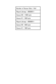
- FIG. 2 is a diagram showing an example of the format of a transmission request that the ONUs 10-1 and 10-2 shown in FIG. 1 transmit to the OLT 30.
- FIG. FIG. 2 shows the format of REPORT information, which is a transmission request specified by IEEE. As shown in FIG. 2, the transmission request includes the amount of data in each queue.
- the OLT 30 has an allocation control section 31 , a transmission request separating section 32 and a frame joining section 33 .
- the transmission request separating unit 32 of the OLT 30 separates the transmission request from the data mixed with the user data frame and the transmission request received by the OLT 30 and outputs the transmission request to the allocation control unit 31 .
- Allocation control unit 31 calculates the amount of data allocated to each LLID based on the received transmission request, and generates a transmission permission including the amount of allocated data.
- Allocation control section 31 outputs a transmission permission as a GATE frame.
- the frame joining unit 33 multiplexes the GATE frame including the transmission permission output from the allocation control unit 31 and the user data received from the network side, and transmits the multiplexed data to each LLID.
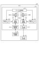
- FIG. 3 is a diagram showing the detailed functional configuration of the OLT 30 shown in FIG.
- the OLT 30 has an allocation control section 31 , a transmission request separating section 32 and a frame joining section 33 .
- the allocation control unit 31 includes a service control unit 311, a plurality of virtual DBAs 100A and 100B, a transfer rule table 312, an aggregation rule table 313, a transmission request analysis unit 314, a transfer control unit 315, and an aggregation control unit 316. , and a frame generator 317 .
- the virtual DBAs 100A and 100B will simply be referred to as virtual DBAs 100 when there is no need to distinguish between them.
- the service control unit 311 receives service requests from network service users.
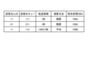
- FIG. 4 is a diagram showing an example of a service request received by the OLT 30 shown in FIG.
- the service request shown in FIG. 4 has ONUs 10-1 and 10-2 as connection destinations, the number of required priority classes is 1 to 8, the minimum guaranteed transmission delay is 1 ms, the guaranteed transmission delay is 2 ms, and the maximum guaranteed transmission delay is 1 ms. It is required to secure resources necessary to maintain service quality such as a bandwidth of 150 Mbps and an average usage bandwidth of 100 Mbps.
- the service control unit 311 can generate a plurality of virtual DBAs 100 according to service requests.
- the virtual DBA 100 may be a software program operating on a server, or may be a hardware module operating on a dedicated LSI.
- the service control unit 311 activates the virtual DBA 100A for QoS control of this service.
- Virtual DBA 100A establishes connections with ONU 10-1 and ONU 10-2 according to the service request, and allocates and secures LLIDs 11 and 21 and queues 111 and 211 for this service.
- service control unit 311 may allocate LLID 11 of ONU 10-1 and allocate unused queue 112, or allocate LLID 12. good too.
- the service control unit 311 can generate a transfer rule table 312 as transfer rule information and an aggregation rule table 313 as aggregation rule information based on the generation result of the virtual DBA 100 .
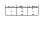
- FIG. 5 is a diagram showing an example of the transfer rule table 312 shown in FIG.
- the transfer rule table 312 shows the correspondence between the source of the transmission request and the virtual DBA 100 of the transfer destination. and transfer destination information indicating the virtual DBA 100 .
- the source information includes, for example, information specifying the logical link connected to the source of the transmission request and the queue provided for the logical link, and the transfer rule table 312 shown in FIG. It contains the number of the queue and the number of the destination virtual DBA 100 as transfer destination information.
- the queue 111 with LLID 11 is associated with the virtual DBA 100A
- the queue 211 with LLID 21 is associated with the virtual DBA 100A
- the queue 112 with LLID 11 is associated with the virtual DBA 100B.
- the transmission request analysis unit 314 analyzes the transmission request output by the transmission request separation unit 32 and outputs the analysis result to the transfer control unit 315 . Based on the analysis result, the transfer control unit 315 extracts the transmission request from the REPORT frame, extracts the LLID as the transmission source information, the information indicating the queue, and the information indicating the data amount of each queue from the transmission request. Based on the obtained information and the transfer rule table 312, the transfer destination virtual DBA 100 is selected. The transfer control unit 315 transfers the transmission request to the selected virtual DBA 100 . For example, when using the transfer rule table 312 shown in FIG. 5, the transfer control unit 315 selects the virtual DBA 100A when the transmission source information of the transmission request indicates the queue 111 of LLID 11, and sends the transmission request to the selected virtual DBA 100A. transfer.
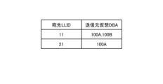
- FIG. 6 is a diagram showing an example of the aggregation rule table 313 shown in FIG.
- the aggregation rule table 313 shows the correspondence relationship between the destination of transmission permission and the virtual DBA 100 that can be the transmission source of transmission permission, and includes destination information for specifying the destination of transmission permission and destination information of the transmission permission source and destination information. and source information indicating the associated virtual DBA 100 . Since LLID11 is used by virtual DBA 100A and virtual DBA 100B, aggregation rule table 313 associates virtual DBAs 100A and 100B with LLID11 as transmission sources. Also, since LLID21 is used by virtual DBA 100A, aggregation rule table 313 associates virtual DBA 100A with LLID21 as a transmission source.
- the aggregation control unit 316 aggregates the transmission permission output by each of the virtual DBAs 100A and 100B for each destination. Specifically, the aggregation control unit 316 adds up the allocated resources calculated by the virtual DBA 100 associated with each LLID, and generates a transmission permission for each LLID. Aggregation control section 316 outputs the generated transmission permission to frame generation section 317 . Frame generating section 317 generates a GATE frame, which is a frame including the transmission permission after aggregation output by aggregation control section 316 , and outputs the generated GATE frame to frame joining section 33 .
- the OLT 30 upon receiving a transmission request, performs a , a virtual DBA 100 to which the received transmission request is to be transferred is selected, and the transmission request is transferred to the selected virtual DBA 100 . Therefore, it is possible to limit the virtual DBA 100 that performs the calculation for granting the transmission permission to the virtual DBA 100 of the transfer destination, thereby suppressing an unnecessary increase in computational resources and reducing resource waste. can be done.
- the amount of transmission permission data is accumulated, and transmission permission aggregated for each transmission permission destination is generated. Therefore, it is possible to efficiently notify the allocated resources, and reduce the waste of the resources required for notification.
- Embodiment 2 differs from the first embodiment in the contents of the transfer rule table 312 .
- FIG. 7 is a diagram showing an example of the transfer rule table 312 generated by the service control unit 311 according to the second embodiment.
- the description of the same parts as in Embodiment 1 will be omitted, and the parts different from Embodiment 1 will be mainly described below.
- the transfer rule table 312 shown in FIG. 7 includes the transfer period and calculation method in addition to the source LLID and source queue as source information and the destination virtual DBA indicating the virtual DBA 100 of the transfer destination.
- the transfer cycle indicates the cycle of transferring the transmission request to the virtual DBA 100 .
- the calculation method indicates the calculation method for data included in the transmission request received by the transfer control unit 315 within the transfer cycle.
- transmission requests are usually collected at intervals of several milliseconds, but the transfer control unit 315 transfers the transmission requests to the virtual DBA 100 at intervals specified by the transfer intervals of the transfer rule table 312 .
- the transfer cycle is lengthened to give permission for transmission in the virtual DBA 100. can be made less frequently, and the waste of computational resources can be reduced. Also, if necessary, it is possible to increase the frequency of calculation for granting transmission permission by limiting to services that require frequent parameter adjustments.
- the calculation method specifies, for example, "integration” or "average” as the calculation method for the data contained in the transmission request received within the transfer cycle.
- the transfer control unit 315 integrates the amount of data of the transmission requests received in one second for transmission requests to be transferred to the virtual DBA 100A. is transferred to the virtual DBA 100A.
- the transfer control unit 315 calculates the average data amount of the transmission requests received in 100 milliseconds, and transfers the transmission requests including the average data amount to the virtual DBA 100B.
- the transfer rule table 312 may specify part of the processing performed by the virtual DBA 100 as the calculation method. In this case, it is possible to shorten the calculation time in the virtual DBA 100 and reduce the calculation resources of the virtual DBA 100 .
- the transfer control unit 315 can reduce the amount of data in the transmission request before transferring, thereby reducing the computational resources in the virtual DBA 100. It becomes possible to By specifying a part of the processing performed by the virtual DBA 100 as the calculation method, it is possible to shorten the calculation time of the virtual DBA 100 and reduce the calculation resources.
- Embodiment 3 differs from Embodiment 1 in the contents of transfer rule table 312 and aggregation rule table 313 .
- FIG. 8 is a diagram showing an example of the transfer rule table 312 generated by the service control unit 311 according to the third embodiment.
- FIG. 9 is a diagram showing an example of the aggregation rule table 313 generated by the service control unit 311 according to the third embodiment.
- the description of the same parts as those in Embodiment 1 will be omitted, and the parts different from those in Embodiment 1 will be mainly described below.
- one destination is specified for one source, but in the transfer rule table 312 shown in FIG. 8, multiple destinations are specified for one source. It is In this case, for example, the transmission request from the queue 111 of LLID 11 is transferred to both the virtual DBAs 100A and 100B, and the multiple virtual DBAs 100A and 100B perform calculations based on the same transmission request. . Therefore, the transmission permission calculated by the virtual DBA 100A and the transmission permission calculated by the virtual DBA 100B may cause duplicate data allocation to the queue 111 of the LLID 11 that is the same source.
- the aggregation rule table 313 shown in FIG. 9 includes, in addition to the destination LLID and source virtual DBA, processing method information that specifies the processing method for aggregating the allocated data amount included in the transmission permission. For example, “maximum value", "average”, etc. can be specified as the processing method.
- Aggregation control section 316 aggregates the allocated data amounts included in a plurality of transmission permits with the same destination according to the processing method information.
- the aggregation control unit 316 determines the allocation data amount allocated by the virtual DBA 100A for permission of transmission addressed to LLID11 and the allocation data amount allocated by the virtual DBA 100B for permission of transmission addressed to LLID11.
- the aggregation control unit 316 takes the average value of the allocated data amount allocated by the virtual DBA 100A for permission of transmission addressed to LLID 21 and the allocated data amount allocated by permission for transmission addressed to LLID 21 by the virtual DBA 100B. Notify the LLID 21 of the permission.
- a processing method is specified in the aggregation rule table 313, and the aggregation control unit 316 performs a calculation for aggregating a plurality of transmission permissions. Even when the virtual DBA 100 generates the transmission grant, it is possible to reduce excessive resource allocation for the same LLID.
- Embodiment 4 differs from the first embodiment in the configuration of the ONU 10 and the transfer rule table 312 .
- the same parts as those of the first embodiment will be omitted, and parts different from the first embodiment will be mainly described.
- the frame format of the transmission request transmitted by the ONU 10 is as shown in FIG.
- a REPORT frame transmitted by the ONU 10 can contain multiple transmission requests as Queue Sets.
- the Queue Sets number can be used as service identification information.
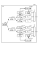
- FIG. 10 is a functional block diagram of ONU 10-1 according to the fourth embodiment.
- ONU 10-1 includes queues 111, 112, 121, 122 and frame reading units 110, 120, as well as LLID allocation unit 130, queue allocation units 131-1, 131-2, and flow check unit 132-11. , 132-12, 132-21, 132-22, flow counters 133-1, 133-2, mapping units 134-1, 134-2, and frame generation units 135-1, 135-2.
- the LLID allocation unit 130 allocates different LLIDs for each service to the input communication traffic.
- the LLID allocation unit 130 outputs the communication traffic allocated to LLID11 to the queue allocation unit 131-1, and outputs the communication traffic allocated to LLID12 to the queue allocation unit 131-2.
- the queue distribution unit 131 distributes input communication traffic to different queues for each service.
- the queue allocation unit 131-1 outputs the communication traffic allocated to the queue 111 to the flow check unit 132-11, and outputs the communication traffic allocated to the queue 112 to the flow check unit 132-12.
- the queue allocation unit 131-2 outputs the communication traffic allocated to the queue 121 to the flow check unit 132-21, and outputs the communication traffic allocated to the queue 122 to the flow check unit 132-22.
- the flow check unit 132 performs service identification for communication traffic to each queue distributed by the LLID distribution unit 130 and the queue distribution unit 131, and measures the amount of data.
- the flow check unit 132 outputs the communication traffic to the corresponding queue, and outputs the measured data amount and service identification information to the flow counter 133 in association with each other.
- the flow check unit 132-11 outputs the communication traffic to the queue 111, and also outputs the measured data amount and service identification information to the flow counter 133-1 in association with each other.
- the flow check unit 132-12 outputs the communication traffic to the queue 112, and also associates the measured data amount with the service identification information and outputs them to the flow counter 133-1.
- the flow check unit 132-21 outputs the communication traffic to the queue 121, and also outputs the measured data amount and service identification information to the queue 121 in association with each other.
- the flow check unit 132-22 outputs the communication traffic to the queue 122, and also outputs the measured data amount and service identification information to the queue 122 in association with each other.
- the flow counter 133 sums up the amount of data for each service based on the amount of data output by the flow check unit 132 and the identification information.
- the flow counter 133 outputs the counting result to the mapping section 134 .
- the flow counter 133-1 outputs the tally result to the mapping section 134-1
- the flow counter 133-2 outputs the tally result to the mapping section 134-2.
- the mapping unit 134 maps the amount of data in the queue for each service based on the aggregate result of the flow counter 133 to the format of the REPORT frame and summarizes them as Queue Sets.
- Mapping section 134 outputs the summarized information to frame generation section 135 .
- mapping section 134-1 outputs the summarized information to frame generation section 135-1
- mapping section 134-2 outputs the summarized information to frame generation section 135-2.
- the frame generation unit 135 generates a REPORT frame including the information output by the mapping unit 134.
- Frame reading section 110 reads frames from frame generating section 135 - 1 and queues 111 and 112 and transmits them to OLT 30 .
- frame reading section 120 reads frames from frame generating section 135 - 2 and queues 121 and 122 and transmits them to OLT 30 .
- the ONU 10-2 can also have a similar configuration.
- FIG. 11 is a diagram showing an example of the transfer rule table 312 used by the OLT 30 that receives a REPORT frame containing a transmission request from the ONU 10-1 shown in FIG.
- the transfer rule table 312 shown in FIG. 11 includes Queue Sets, which is service identification information, in addition to the source LLID and source queue, which are source information, and the destination virtual DBA. Since the transfer rule table 312 includes service identification information, the transfer control unit 315 selects the transfer destination virtual DBA 100 for each Queue Sets of the REPORT frame in addition to the source information when receiving a REPORT frame containing a transmission request. By doing so, it is possible to select a forwarding destination for each service even if the source information is the same.
- the transfer rule information used by the OLT 30 includes a Queue Sets number that can be used as service identification information, and the transfer control unit 315 is associated with each Queue Sets.
- a virtual DBA 100 is selected and a transmission request is transferred to the selected virtual DBA 100 .
- the ONU 10, which is the source of the transmission request, has a flow check unit 132 that measures the amount of data for each service, a flow counter 133 that tallies the amount of data for each service based on the measurement result of the flow check unit 132, and a flow counter 133 that counts the amount of data for each service.
- It has a mapping unit 134 that maps the service identification information and the amount of data for each service to the format of the REPORT frame including the transmission request based on the counted result of the counter 133 .
- Each function of OLT 30 and ONU 10 is implemented by a processing circuit.
- These processing circuits may be implemented by dedicated hardware, or may be control circuits using a CPU (Central Processing Unit).
- CPU Central Processing Unit
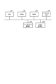
- FIG. 12 is a diagram showing dedicated hardware for implementing the functions of the OLT 30 and ONU 10 according to the first to fourth embodiments.
- the processing circuit 90 is a single circuit, a composite circuit, a programmed processor, a parallel programmed processor, an ASIC (Application Specific Integrated Circuit), an FPGA (Field Programmable Gate Array), or a combination thereof.
- ASIC Application Specific Integrated Circuit
- FPGA Field Programmable Gate Array
- each of the OLT 30 and ONU 10 may be realized by the hardware configuration shown in FIG. 13, for example.
- FIG. 13 is a diagram showing an example of a configuration for implementing the functions of the OLT 30 and ONU 10 according to the first to fourth embodiments using a CPU.
- Each of the OLT 30 and the ONU 10 includes, for example, a CPU 91, a ROM (Read Only Memory) 92, a RAM (Random Access Memory) 93, a packet memory 94, an Ethernet (registered trademark) communication IF (InterFace) 95, and a PON communication IF96.
- the CPU 91 is an example of a processor, and is also called an arithmetic unit, microprocessor, microcomputer, DSP (Digital Signal Processor), and the like.
- ROM 92, RAM 93 and packet memory 94 are examples of memory.
- the functions of each part of the OLT 30 and ONU 10 are implemented by software, firmware, or a combination of software and firmware.
- Software and firmware are written as programs and stored in memory.
- the function of each unit is realized by the CPU 91 reading out and executing a program stored in the memory. Note that the program may be provided while being stored in a storage medium, or may be provided via a communication channel.
- each function of each part of the OLT 30 and ONU 10 may be realized by individual processing circuits, or a plurality of functions may be collectively realized by one processing circuit. Also, part of the function of each part may be realized by dedicated hardware, and part thereof may be realized by software, firmware, or the like.
- 1 optical access network system 10, 10-1, 10-2 ONU, 11, 12, 21, 22 LLID, 30 OLT, 31 allocation control unit, 32 transmission request separation unit, 33 frame joining unit, 90 processing circuit, 91 CPU, 92 ROM, 93 RAM, 94 packet memory, 95 Ethernet communication IF, 96 PON communication IF, 100, 100A, 100B virtual DBA, 110, 120, 210, 220 frame reading unit, 111, 112, 121, 122, 211 , 212, 221, 222 queues, 130 LLID allocation unit, 131, 131-1, 131-2 queue allocation units, 132, 132-11, 132-12, 132-21, 132-22 flow check unit, 133 , 133-1, 133-2 flow counter, 134, 134-1, 134-2 mapping unit, 135, 135-1, 135-2 frame generation unit, 311 service control unit, 312 transfer rule table, 313 aggregation rule table , 314 transmission request analysis unit, 315 transfer control unit, 316 aggregation control unit, 317 frame
Landscapes
- Engineering & Computer Science (AREA)
- Computer Networks & Wireless Communication (AREA)
- Signal Processing (AREA)
- Small-Scale Networks (AREA)
Abstract
Description
図1は、実施の形態1にかかる光アクセスネットワークシステム1の構成を示す図である。光アクセスネットワークシステム1は、複数の加入者側の光回線終端装置であるONU10-1,10-2と、事業者側の光回線終端装置であるOLT30とを有する。以下、同様の機能を有する複数の構成要素のそれぞれを区別する場合、共通する符号の後にハイフンに続けて異なる符号を付することにより区別し、同様の機能を有する複数の構成要素のそれぞれを区別する必要がない場合、共通の符号のみを付することがある。例えば、ONU10-1,10-2のそれぞれを区別する必要がない場合、ONU10と称する。
実施の形態2は、実施の形態1と比較して、転送ルールテーブル312の内容が異なる。図7は、実施の形態2にかかるサービス制御部311が生成する転送ルールテーブル312の一例を示す図である。実施の形態2におけるシステム構成および各装置の機能構成において実施の形態1と同様の部分については説明を省略し、以下、実施の形態1と異なる部分について主に説明する。
実施の形態3は、実施の形態1と比較して、転送ルールテーブル312および集約ルールテーブル313の内容が異なる。図8は、実施の形態3にかかるサービス制御部311が生成する転送ルールテーブル312の一例を示す図である。図9は、実施の形態3にかかるサービス制御部311が生成する集約ルールテーブル313の一例を示す図である。実施の形態3におけるシステム構成および各装置の機能構成において実施の形態1と同様の部分については説明を省略し、以下、実施の形態1と異なる部分について主に説明する。
実施の形態4では、ONU10の構成および転送ルールテーブル312が実施の形態1と異なる。以下、実施の形態1と同様の部分については詳細な説明を省略し、実施の形態1と異なる部分について主に説明する。
Claims (13)
- 加入者側の光回線終端装置が送信する送信要求に応じて当該送信要求の送信元に対して割り当てる帯域を算出して送信許可を出力する仮想動的帯域割当部を複数動作させる事業者側の光回線終端装置であって、
サービス要求に応じて複数の前記仮想動的帯域割当部を生成するサービス制御部と、
前記送信要求を受信すると、前記送信要求の送信元と転送先の前記仮想動的帯域割当部との対応関係を示す転送ルール情報に基づいて、受信した前記送信要求の転送先である前記仮想動的帯域割当部を選択し、選択した前記仮想動的帯域割当部に前記送信要求を転送する転送制御部と、
前記送信許可の宛先と前記送信許可の送信元になり得る前記仮想動的帯域割当部との対応関係を示す集約ルール情報に基づいて、前記仮想動的帯域割当部が出力する前記送信許可を集約する集約制御部と、
を備えることを特徴とする光回線終端装置。 - 前記サービス制御部は、前記仮想動的帯域割当部の生成結果に基づいて、前記転送ルール情報および前記集約ルール情報を生成することを特徴とする請求項1に記載の光回線終端装置。
- 前記転送ルール情報は、前記送信要求の送信元を特定するための送信元情報と、前記送信元情報と対応づけられた転送先の前記仮想動的帯域割当部を示す転送先情報とを含むことを特徴とする請求項1または2に記載の光回線終端装置。
- 前記送信元情報は、前記送信要求の送信元に接続される論理リンクおよび当該論理リンクに備わるキューを特定する情報を含み、
前記転送制御部は、前記送信要求を受信すると、受信した前記送信要求から前記論理リンクおよび前記キューを特定する情報を抽出し、前記転送ルール情報に基づいて、抽出した前記論理リンクおよび前記キューに対応づけられた前記仮想動的帯域割当部を選択することを特徴とする請求項3に記載の光回線終端装置。 - 前記転送ルール情報は、送信要求を前記仮想動的帯域割当部に転送する周期を示す転送周期情報をさらに含み、
前記転送制御部は、前記転送周期情報に基づいた周期で前記送信要求を転送することを特徴とする請求項1から4のいずれか1項に記載の光回線終端装置。 - 前記転送ルール情報は、前記転送周期情報が示す周期内に前記転送制御部が受信した前記送信要求に含まれるデータの演算方法を指定する演算方法情報をさらに含み、
前記転送制御部は、前記演算方法情報に従って前記送信要求を処理した後の前記送信要求を転送することを特徴とする請求項5に記載の光回線終端装置。 - 前記演算方法情報は、前記送信要求を受信する前記仮想動的帯域割当部が行う処理の一部を指定することを特徴とする請求項6に記載の光回線終端装置。
- 前記集約ルール情報は、前記送信許可の宛先を特定するための宛先情報と、前記送信許可の送信元であり前記宛先情報と対応づけられた前記仮想動的帯域割当部を示す送信元情報とを含み、
前記集約制御部は、前記送信許可の宛先毎に前記送信許可を集約することを特徴とする請求項1から7のいずれか1項に記載の光回線終端装置。 - 前記集約ルール情報は、前記送信許可に含まれる割当データ量を集約する際の処理方法を指定する処理方法情報をさらに含み、
前記集約制御部は、宛先が同一の複数の送信許可に含まれる前記割当データ量を、前記処理方法情報に従って集約することを特徴とする請求項8に記載の光回線終端装置。 - 前記処理方法は、複数の前記割当データ量の最大値または平均値をとることであり、
前記集約制御部は、前記処理方法情報に従って、前記割当データ量の最大値または平均値をとって前記送信許可の宛先に送信することを特徴とする請求項9に記載の光回線終端装置。 - 送信要求を送信する加入者側の光回線終端装置と、
前記送信要求を受信する請求項1から10のいずれか1項に記載の光回線終端装置と、
を備えることを特徴とする光アクセスネットワークシステム。 - 前記転送ルール情報は、サービス識別情報を含み、
前記転送制御部は、前記サービス識別情報に基づいて、転送先の前記仮想動的帯域割当部を選択し、
前記加入者側の光回線終端装置は、
サービス毎のデータ量を計測するフローチェック部と、
前記フローチェック部の計測結果に基づいて、サービス毎のデータ量を集計するフローカウンタと、
前記フローカウンタの集計結果に基づいて、サービス識別情報と、サービス毎のデータ量とを前記送信要求を含むフレームのフォーマットにマッピングするマッピング部と、
を有することを特徴とする請求項11に記載の光アクセスネットワークシステム。 - 事業者側の光回線終端装置が動作させる仮想動的帯域割当部が、加入者側の光回線終端装置が送信する送信要求に応じて、当該送信要求の送信元に対して割り当てる帯域を算出して送信許可を出力する光通信方法であって、
サービス要求に応じて複数の前記仮想動的帯域割当部を生成するステップと、
前記送信要求を受信すると、前記送信要求の送信元と転送先の前記仮想動的帯域割当部との対応関係を示す転送ルール情報に基づいて、受信した前記送信要求の転送先である前記仮想動的帯域割当部を選択するステップと、
選択した前記仮想動的帯域割当部に前記送信要求を転送するステップと、
前記送信許可の宛先と前記送信許可の送信元になり得る前記仮想動的帯域割当部との対応関係を示す集約ルール情報に基づいて、前記仮想動的帯域割当部が出力する前記送信許可を集約するステップと、
を含むことを特徴とする光通信方法。
Priority Applications (4)
| Application Number | Priority Date | Filing Date | Title |
|---|---|---|---|
| JP2023544604A JP7374394B2 (ja) | 2021-11-26 | 2021-11-26 | 光回線終端装置、光アクセスネットワークシステムおよび光通信方法 |
| PCT/JP2021/043432 WO2023095296A1 (ja) | 2021-11-26 | 2021-11-26 | 光回線終端装置、光アクセスネットワークシステムおよび光通信方法 |
| CN202180104350.0A CN118266194A (zh) | 2021-11-26 | 2021-11-26 | 光线路终端装置、光接入网络系统和光通信方法 |
| US18/634,349 US20240267659A1 (en) | 2021-11-26 | 2024-04-12 | Optical line terminal, optical access network system, and optical communication method |
Applications Claiming Priority (1)
| Application Number | Priority Date | Filing Date | Title |
|---|---|---|---|
| PCT/JP2021/043432 WO2023095296A1 (ja) | 2021-11-26 | 2021-11-26 | 光回線終端装置、光アクセスネットワークシステムおよび光通信方法 |
Related Child Applications (1)
| Application Number | Title | Priority Date | Filing Date |
|---|---|---|---|
| US18/634,349 Continuation US20240267659A1 (en) | 2021-11-26 | 2024-04-12 | Optical line terminal, optical access network system, and optical communication method |
Publications (1)
| Publication Number | Publication Date |
|---|---|
| WO2023095296A1 true WO2023095296A1 (ja) | 2023-06-01 |
Family
ID=86539230
Family Applications (1)
| Application Number | Title | Priority Date | Filing Date |
|---|---|---|---|
| PCT/JP2021/043432 Ceased WO2023095296A1 (ja) | 2021-11-26 | 2021-11-26 | 光回線終端装置、光アクセスネットワークシステムおよび光通信方法 |
Country Status (4)
| Country | Link |
|---|---|
| US (1) | US20240267659A1 (ja) |
| JP (1) | JP7374394B2 (ja) |
| CN (1) | CN118266194A (ja) |
| WO (1) | WO2023095296A1 (ja) |
Cited By (1)
| Publication number | Priority date | Publication date | Assignee | Title |
|---|---|---|---|---|
| CN117395783A (zh) * | 2023-12-13 | 2024-01-12 | 武汉长光科技有限公司 | 信号质量优化方法、装置、电子设备及存储介质 |
Citations (3)
| Publication number | Priority date | Publication date | Assignee | Title |
|---|---|---|---|---|
| US20070041384A1 (en) * | 2005-07-20 | 2007-02-22 | Immenstar Inc. | Intelligent bandwidth allocation for ethernet passive optical networks |
| JP2019179994A (ja) * | 2018-03-30 | 2019-10-17 | 沖電気工業株式会社 | 光通信システム、親局装置、帯域割当装置、帯域割当プログラム及び帯域割当方法 |
| JP2020510357A (ja) * | 2017-03-16 | 2020-04-02 | ザ・プロボスト, フェローズ, ファウンデーション・スカラーズ, アンド・ジ・アザー・メンバーズ・オブ・ボード, オブ・ザ・カレッジ・オブ・ザ・ホーリー・アンド・アンディバイデッド・トリニティ・オブ・クイーン・エリザベス・ニア・ダブリンThe Provost, Fellows, Foundation Scholars, And The Other Members Of Board, Of The College Of The Holy And Undivided Trinity Of Queen Elizabeth Near Dublin | マルチテナント受動光ネットワークにおける動的帯域幅割り当て(dba)を仮想化するシステム及び方法 |
-
2021
- 2021-11-26 WO PCT/JP2021/043432 patent/WO2023095296A1/ja not_active Ceased
- 2021-11-26 CN CN202180104350.0A patent/CN118266194A/zh active Pending
- 2021-11-26 JP JP2023544604A patent/JP7374394B2/ja active Active
-
2024
- 2024-04-12 US US18/634,349 patent/US20240267659A1/en active Pending
Patent Citations (3)
| Publication number | Priority date | Publication date | Assignee | Title |
|---|---|---|---|---|
| US20070041384A1 (en) * | 2005-07-20 | 2007-02-22 | Immenstar Inc. | Intelligent bandwidth allocation for ethernet passive optical networks |
| JP2020510357A (ja) * | 2017-03-16 | 2020-04-02 | ザ・プロボスト, フェローズ, ファウンデーション・スカラーズ, アンド・ジ・アザー・メンバーズ・オブ・ボード, オブ・ザ・カレッジ・オブ・ザ・ホーリー・アンド・アンディバイデッド・トリニティ・オブ・クイーン・エリザベス・ニア・ダブリンThe Provost, Fellows, Foundation Scholars, And The Other Members Of Board, Of The College Of The Holy And Undivided Trinity Of Queen Elizabeth Near Dublin | マルチテナント受動光ネットワークにおける動的帯域幅割り当て(dba)を仮想化するシステム及び方法 |
| JP2019179994A (ja) * | 2018-03-30 | 2019-10-17 | 沖電気工業株式会社 | 光通信システム、親局装置、帯域割当装置、帯域割当プログラム及び帯域割当方法 |
Non-Patent Citations (2)
| Title |
|---|
| HIROYUKI SAITO, YOSHIHIRO NAKAHIRA, MASAYUKI KASHIMA, HIRONORI SASAKI, AKIKO NAGASAWA, KENICHI NAKURA, YUKIO HIRANO, SEIJI KOZAKI,: "New Architecture to Flexibly and Dynamically Control MFH/MBH for IoT services", IEICE TECHNICAL REPORT, CS, IEICE, JP, vol. 118, no. 208 (CS2018-50), 30 August 2018 (2018-08-30), JP, pages 53 - 58, XP009546094 * |
| MASAHIRO SARASHINA, HIROYUKI SAITO, MASAYUKI KASHIMA, HIRONORI SASAKI, KENICHI NAKURA, SEIJI KOZAKI, HIDENORI INOUCHI, SHU YAMAMOT: "Demonstration of Optical Access Network Virtualization for Full-scale spread of 5G/IoT -- Management and allocation of PON resources --", IEICE TECHNICAL REPORT, CS, IEICE, JP, vol. 120, no. 164 (CS2020-38), 3 September 2020 (2020-09-03), JP, pages 20 - 23, XP009546092 * |
Cited By (2)
| Publication number | Priority date | Publication date | Assignee | Title |
|---|---|---|---|---|
| CN117395783A (zh) * | 2023-12-13 | 2024-01-12 | 武汉长光科技有限公司 | 信号质量优化方法、装置、电子设备及存储介质 |
| CN117395783B (zh) * | 2023-12-13 | 2024-02-27 | 武汉长光科技有限公司 | 信号质量优化方法、装置、电子设备及存储介质 |
Also Published As
| Publication number | Publication date |
|---|---|
| JPWO2023095296A1 (ja) | 2023-06-01 |
| CN118266194A (zh) | 2024-06-28 |
| JP7374394B2 (ja) | 2023-11-06 |
| US20240267659A1 (en) | 2024-08-08 |
Similar Documents
| Publication | Publication Date | Title |
|---|---|---|
| US8913549B2 (en) | Congestion control in an optical line terminal | |
| KR100506209B1 (ko) | 이더넷 수동 광 가입자망에서 다중 서비스를 고려한 동적대역폭 할당방법 | |
| KR100698571B1 (ko) | 패시브형 광 네트워크에서의 동적 대역폭 할당 방법 | |
| CN101771902B (zh) | 分配无源光网络上行带宽的方法、系统及装置 | |
| US8259751B2 (en) | Bandwidth-allocating device and method | |
| CN101087238B (zh) | 无源光网络的动态带宽分配装置及方法 | |
| US8526815B2 (en) | Dynamic bandwidth allocation for congestion management in PON channel aggregation | |
| CN102104549B (zh) | 无源光网络的动态带宽分配方法及装置 | |
| US20120148247A1 (en) | Method for soft bandwidth limiting in dynamic bandwidth allocation | |
| US9203545B2 (en) | Method, device, and nested system for allocating uplink and downlink bandwidth | |
| EP2975810A1 (en) | Method and system for improving bandwidth allocation efficiency | |
| CN104735555B (zh) | 一种无源光网络的带宽分配方法 | |
| CN1953353B (zh) | 基于吉比特无源光网络中多等级服务的动态带宽分配方法 | |
| JP6765572B1 (ja) | ネットワーク制御装置、通信リソース割り当て方法および通信システム | |
| US20250007619A1 (en) | Bandwidth allocation method and associated optical line terminal | |
| JP6601526B2 (ja) | 光通信システム、親局装置、帯域割当装置、帯域割当プログラム及び帯域割当方法 | |
| JP7374394B2 (ja) | 光回線終端装置、光アクセスネットワークシステムおよび光通信方法 | |
| JP7017300B2 (ja) | 通信装置、設定方法及び通信プログラム | |
| JP2004336578A (ja) | ポイント・マルチポイント光伝送システムおよび局側通信装置 | |
| JP2017139547A (ja) | 通信装置及びその動作方法並びにプログラム | |
| JP2004289780A (ja) | 光加入者線端局装置、光加入者線終端装置およびそれらによって用いられる帯域割当方法 | |
| JP5900375B2 (ja) | 通信システムおよび通信装置、通信帯域制御方法 | |
| US12425754B2 (en) | Optical line terminal, optical communication system, bandwidth allocation method, control circuit, and storage medium | |
| JP4877483B2 (ja) | 送信割当て方法及び装置 | |
| KR20050109873A (ko) | 이더넷 기반의 수동 광 네트워크에서 공평성을 지원하는동적대역할당 방법 및 그 장치 |
Legal Events
| Date | Code | Title | Description |
|---|---|---|---|
| 121 | Ep: the epo has been informed by wipo that ep was designated in this application |
Ref document number: 21965667 Country of ref document: EP Kind code of ref document: A1 |
|
| WWE | Wipo information: entry into national phase |
Ref document number: 2023544604 Country of ref document: JP |
|
| WWE | Wipo information: entry into national phase |
Ref document number: 202180104350.0 Country of ref document: CN |
|
| NENP | Non-entry into the national phase |
Ref country code: DE |
|
| 122 | Ep: pct application non-entry in european phase |
Ref document number: 21965667 Country of ref document: EP Kind code of ref document: A1 |