WO2023089740A1 - 換気空気調和制御システムおよび換気空気調和制御装置 - Google Patents
換気空気調和制御システムおよび換気空気調和制御装置 Download PDFInfo
- Publication number
- WO2023089740A1 WO2023089740A1 PCT/JP2021/042469 JP2021042469W WO2023089740A1 WO 2023089740 A1 WO2023089740 A1 WO 2023089740A1 JP 2021042469 W JP2021042469 W JP 2021042469W WO 2023089740 A1 WO2023089740 A1 WO 2023089740A1
- Authority
- WO
- WIPO (PCT)
- Prior art keywords
- temperature
- ventilation
- air conditioning
- data
- position information
- Prior art date
- Legal status (The legal status is an assumption and is not a legal conclusion. Google has not performed a legal analysis and makes no representation as to the accuracy of the status listed.)
- Ceased
Links
Images


Classifications
-
- F—MECHANICAL ENGINEERING; LIGHTING; HEATING; WEAPONS; BLASTING
- F24—HEATING; RANGES; VENTILATING
- F24F—AIR-CONDITIONING; AIR-HUMIDIFICATION; VENTILATION; USE OF AIR CURRENTS FOR SCREENING
- F24F11/00—Control or safety arrangements
- F24F11/70—Control systems characterised by their outputs; Constructional details thereof
- F24F11/72—Control systems characterised by their outputs; Constructional details thereof for controlling the supply of treated air, e.g. its pressure
- F24F11/74—Control systems characterised by their outputs; Constructional details thereof for controlling the supply of treated air, e.g. its pressure for controlling air flow rate or air velocity
Definitions
- the present disclosure relates to a ventilation air conditioning control system and a ventilation air conditioning control device for controlling indoor ventilation air conditioning.
- air-conditioning systems that manage air conditioning in buildings where heat sources such as heat-generating equipment are installed use methods that use cooling only, forced exhaust of the heat generated by heat-generating equipment, or a combination of cooling and exhaust. is used.
- As a countermeasure against the temperature rise inside the building due to the heat generated by the heat-generating equipment it is generally better to exhaust the heat inside the building to the outside using an exhaust ventilation fan than to manage the air conditioning only by cooling. Power consumption can be reduced.
- Patent Literature 1 mentions the problem that when the exhaust system performs exhaust, the cool air supplied by the cool air supply system is also excessively exhausted, resulting in energy loss.
- Patent Document 1 reference is made to the temperature in the vicinity of the heat source to control whether to operate or stop the exhaust system device, and the environment in which the cold air supply system device is operated and to stop.
- An air conditioning system is disclosed that controls whether an exhaust system device is activated or deactivated based on operating standards that differ depending on the environment.
- Patent Document 2 in order to control an air conditioning system such as a data center with higher accuracy, based on three-dimensional temperature position information obtained from a plurality of temperature sensors, temperature-controlled air An air conditioning system is disclosed that delivers a
- the present disclosure has been made in view of the above, and provides a ventilation air conditioning control system that can prevent temperature rise in a work area where workers are located due to exhaust heat of a heat source inside a building. With the goal.
- the ventilation air conditioning control system includes, as constituent equipment, an exhaust ventilation fan for discharging the air inside the building in which the heat source device is provided to the outside. At least one of a supply ventilation fan for supplying outdoor air to the inside of the building, a circulation fan for circulating the air inside the building, and an air conditioner for cooling the inside of the building. Equipped with a ventilation and air conditioning system including.
- the ventilation and air conditioning control system includes a work area temperature sensor that measures the temperature of the work area, which is a predetermined area inside the building where workers are present and is affected by the heat generated by the heat source equipment, and an outdoor air a temperature sensor system comprising a plurality of temperature sensors including an external temperature sensor for measuring the temperature of the
- the ventilation and air conditioning control system includes device operation data indicating the operating status of the component devices of the ventilation and air conditioning system, device location information indicating the position of the component devices, temperature data obtained from a plurality of temperature sensors, and the positions of the plurality of temperature sensors.
- a control means is provided for individually controlling the operation of the components of the ventilation and air conditioning system to bring the temperature of the work area closer to a predetermined target temperature based on the temperature position information indicating the temperature position information.
- a ventilation and air conditioning control system that can prevent a temperature rise in the work area where workers are located due to the exhaust heat of the heat source inside the building.
- FIG. 1 is a first schematic diagram showing an example in which the ventilation and air conditioning control system according to Embodiment 1 is applied to a factory building;
- Schematic plan view of the factory building shown in FIG. A block diagram showing the functional configuration of the ventilation and air conditioning control system according to the first embodiment.
- Block diagram showing the functional configuration of the ventilation fan of the ventilation air conditioning control system according to the first embodiment Block diagram showing the functional configuration of the circulation fan of the ventilation air conditioning control system according to the first embodiment.
- FIG. 2 is a block diagram showing the functional configuration of the air conditioner of the ventilation air conditioning control system according to Embodiment 1.
- FIG. FIG. 2 is a block diagram showing the functional configuration of the temperature sensor of the ventilation and air conditioning control system according to the first embodiment; Block diagram showing the functional configuration of the ventilation air conditioning control device of the control means of the ventilation air conditioning control system according to the first embodiment FIG.
- FIG. 2 is a diagram showing a hardware configuration example for realizing control means of the ventilation and air conditioning control system according to the first embodiment
- 4 is a flow chart showing the operation procedure of the ventilation and air conditioning control system according to the first embodiment
- Block diagram showing the functional configuration of the ventilation and air conditioning control system according to the second embodiment Flowchart showing the operation procedure of the ventilation and air conditioning control system according to the second embodiment
- Block diagram showing the functional configuration of the ventilation air conditioning control system according to the third embodiment Flowchart showing the operation procedure of the ventilation and air conditioning control system according to the third embodiment
- Block diagram showing the functional configuration of the ventilation air conditioning control system according to the fourth embodiment Flowchart showing the operation procedure of the ventilation and air conditioning control system according to the fourth embodiment FIG.
- FIG. 11 is a block diagram showing the configuration of a learning device according to a fifth embodiment
- 14 is a flow chart showing a processing procedure of learning processing by the learning device according to the fifth embodiment
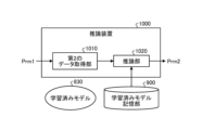
- FIG. 11 is a block diagram showing the configuration of an inference device according to a fifth embodiment
- 12 is a flow chart showing processing procedures of inference processing by the inference device according to the fifth embodiment and control processing by the ventilation and air conditioning control device
- FIG. 4 is a diagram showing an example of a hardware configuration of processing circuits according to the first to fifth embodiments
- FIG. 1 is a first schematic diagram showing an example in which the ventilation and air conditioning control system 100 according to the first embodiment is applied to a factory building 701.
- FIG. 2 is a second schematic diagram showing an example in which the ventilation and air conditioning control system 100 according to the first embodiment is applied to a factory building 701.
- FIG. 3 is a third schematic diagram showing an example in which the ventilation and air conditioning control system 100 according to the first embodiment is applied to a factory building 701.
- FIGS. 1 and 2 show a case where the ventilation/air conditioning control system 100 is applied to a factory building 701 and the interior of the building 701 is a ventilation/air conditioning target space.
- FIG. 3 shows a state in which the control means 400 of the ventilation and air conditioning control system 100 according to Embodiment 1 is arranged in the control room 702 of the factory.
- FIG. 4 is a schematic plan view of the factory building 701 shown in FIG. FIG. 4 schematically shows the configuration arranged in the building 701 that can be seen through the ceiling of the building 701 .
- the local exhaust ventilation fan 230 and the duct 231 are shown in the in-plane direction of the floor surface 701b of the building at positions beside the manufacturing equipment 703 and the heat source equipment 706. 2, the local exhaust ventilation fan 230 and the duct 231 are actually arranged above the manufacturing equipment 703 and the heat source equipment 706 as shown in FIGS.
- FIG. 5 is a block diagram showing the functional configuration of the ventilation/air conditioning control system 100 according to the first embodiment.
- the ventilation and air conditioning control system 100 is a system that performs at least one of ventilation and air conditioning inside the building 701 .
- a hood for collecting hot air is provided at the intake port at the lower end of the duct 231 .
- the width direction of the building 701 in FIG. 1 is defined as the X direction
- the depth direction of the building 701 is defined as the Y direction
- the height direction of the building 701 is defined as the Z direction.
- the X direction and the Y direction are directions parallel to the horizontal direction.
- the Z direction is a direction parallel to the vertical direction.
- the direction from left to right in FIG. 1 is the + direction of the X direction
- the direction from right to left in FIG. 1 is the - direction of the X direction.
- the direction from the upper right to the lower left in FIG. 1 is the + direction of the Y direction
- the direction from the lower left to the upper right in FIG. 1 is the - direction of the Y direction.
- the direction from the bottom to the top in FIG. 1 is the + direction of the Z direction
- the direction from the top to the bottom in FIG. 1 is the ⁇ direction of the Z direction.
- the factory includes a building 701, which is a closed system space, and a control room 702 in which the control means 400 is installed.
- the building 701 and the control room 702 may be provided at the same location within the factory. That is, the control room 702 may be provided inside the building 701 . Also, the building 701 and the control room 702 may be provided at different locations within the factory.
- manufacturing equipment 703 is arranged inside building 701 .
- the manufacturing equipment 703 includes a heat source device 706 that generates heat during operation. That is, heat is generated by the operation of the manufacturing apparatus 703 .
- the manufacturing apparatus 703 is not an apparatus arranged for the purpose of warming the interior of the building 701, but an apparatus installed for the purpose of manufacturing products.
- high-temperature air 705 whose temperature is relatively higher than that of other areas of the building 701 due to exhaust heat emitted from the manufacturing equipment 703 spreads around the manufacturing equipment 703 .
- the high-temperature air 705 spread around the manufacturing equipment 703 is exhausted to the outside of the building 701 by operating the later-described exhaust ventilation fan 210 or local exhaust ventilation fan 230 of the ventilation air conditioning control system 100 .
- the ventilation and air conditioning control system 100 used in the building 701 includes a ventilation and air conditioning system 200, a temperature sensor system 300, and control means 400.
- the ventilation and air conditioning system 200 adjusts the air environment inside the building 701 by ventilating or air conditioning the interior of the building 701 .
- the ventilation air conditioning system 200 includes one or more exhaust ventilation fans 210, one or more supply ventilation fans 220, one or more local exhaust ventilation fans 230, one or more circulation fans 240, One or more air conditioners 250 and a ventilation air conditioning control interface 260 are provided.
- the ventilation air conditioning control interface 260 is an interface connected with the temperature sensor system 300 and the control means 400 . Below, the interface is abbreviated as I/F. For example, below, the ventilation air conditioning control interface 260 is abbreviated as ventilation air conditioning control I/F260. Ventilation air conditioning control I/F 260 is an I/F used for control of exhaust ventilation fan 210 , supply ventilation fan 220 , local exhaust ventilation fan 230 , circulation fan 240 and air conditioner 250 by control means 400 . That is, the ventilation air conditioning control I/F 260 mediates information communication between the exhaust ventilation fan 210, the supply ventilation fan 220, the local exhaust ventilation fan 230, the circulation fan 240, the air conditioner 250, and the control means 400. do.
- the exhaust ventilation fan 210 is a ventilation facility for ventilating the inside of the building 701, and is installed on the outer wall 701a of the building 701 that separates the inside of the building 701 from the outside of the building 701. It is an exhaust device for discharging to the outside which is the outside.
- the exhaust ventilation fan 210 has a function corresponding to a general exhaust ventilation fan.
- the exhaust ventilation fan 210 can communicate with the control means 400 via the ventilation air conditioning control I/F 260 and can be controlled by the control means 400 .
- the air supply ventilation fan 220 is a ventilation facility for ventilating the inside of the building 701, is installed on the outer wall 701a of the building 701, and is an air supply for supplying outside air, which is the outdoor air of the building 701, to the inside of the building 701. Air equipment.
- the air supply ventilation fan 220 has a function corresponding to a general air supply ventilation fan.
- the ventilation fan 220 for supplying air can communicate with the control means 400 via the ventilation/air conditioning control I/F 260 and can be controlled by the control means 400 .
- the local exhaust ventilation fan 230 is a ventilation facility for ventilating the inside of the building 701, and is installed in the inside of the building 701 at a position near the manufacturing equipment 703. It is a local exhaust equipment for discharging to the outside of the building.
- the duct 231 is an air guide path for sucking the air inside the building 701 by the airflow generated by the ventilation fan 230 for local exhaust and for letting the air inside the building 701 flow outside. Note that an exhaust hood for sucking the air inside the building 701 may be used instead of the duct 231 as the air guide path.
- FIG. 6 is a block diagram showing the functional configuration of the ventilation fan 10 of the ventilation air conditioning control system 100 according to the first embodiment.
- the configurations of the exhaust ventilation fan 210, the supply ventilation fan 220, and the local exhaust ventilation fan 230 will be described below. Since the exhaust ventilation fan 210, the supply ventilation fan 220, and the local exhaust ventilation fan 230 have the same basic configuration, the exhaust ventilation fan 210, the supply ventilation fan 220, and the local exhaust ventilation fan 230 are referred to as the ventilation fan 10 here.
- the ventilation fan 10 includes a ventilation unit 11, a ventilation communication unit 12, a ventilation storage unit 13, and a ventilation control unit 14.
- the ventilation section 11 ventilates the interior of the building 701 .
- the ventilation unit 11 of the exhaust ventilation fan 210 and the local exhaust ventilation fan 230 exhausts the air inside the building 701 to the outside.
- the ventilation unit 11 of the air supply ventilation fan 220 supplies outside air to the interior of the building 701 .
- the ventilation communication unit 12 communicates with the control means 400 .
- the ventilation storage unit 13 stores various information used for controlling the ventilation fan 10 .
- the ventilation storage unit 13 stores the position information of the place where the ventilation fan 10 is installed, which is the equipment position information of the ventilation fan 10 .
- the ventilation control unit 14 controls the operation of the ventilation fan 10.
- the ventilation control unit 14 receives the operation instruction information transmitted from the control means 400 via the ventilation communication unit 12, and controls the operation of the ventilation fan 10 based on the operation instruction information. That is, the ventilation control unit 14 controls the operation of the ventilation fan 10, such as the operation, stop, and adjustment of the air volume of the ventilation fan 10, based on the operation instruction information.
- the ventilation unit 11, the ventilation communication unit 12, the ventilation storage unit 13, and the ventilation control unit 14 can exchange information with each other.
- the ventilation communication unit 12, the ventilation storage unit 13, and the ventilation control unit 14 may be mounted inside the ventilation fan 10, or incorporated into other devices such as the ventilation air conditioning control I/F 260 or the control means 400. It may be
- the circulation blower 240 is a blower device that is placed inside the building 701 and sucks in the air inside the building 701 and blows it into the building 701 to circulate the air inside the building 701 .
- the circulation fan 240 has a function corresponding to a fan such as a general fan or an air carrier fan.
- the circulation fan 240 can communicate with the control means 400 via the ventilation air conditioning control I/F 260 and can be controlled by the control means 400 .
- FIG. 7 is a block diagram showing the functional configuration of the circulation fan 240 of the ventilation air conditioning control system 100 according to the first embodiment.
- the circulation fan 240 includes a fan section 241 , a fan communication section 242 , a fan storage section 243 , and a fan control section 244 .
- the air blower 241 blows air to circulate the indoor air of the building 701 .
- the fan communication unit 242 communicates with the control means 400 .
- the blow storage unit 243 stores various information used for controlling the circulation blower 240 .
- the air blow storage unit 243 stores the position information of the place where the circulation fan 240 is installed, which is the equipment position information of the circulation fan 240 .
- the blower control unit 244 controls the operation of the circulation blower 240 .
- the blower control unit 244 receives the operation instruction information transmitted from the control means 400 via the blower communication unit 242, and controls the operation of the circulation blower 240 based on the operation instruction information. That is, the air-blowing control unit 244 controls the operation of the circulation fan 240 such as operation, stop, and adjustment of the air volume of the circulation fan 240 based on the operation instruction information.
- the blower unit 241, the blower communication unit 242, the blower storage unit 243, and the blower control unit 244 can exchange information with each other.
- the blow communication unit 242, the blow storage unit 243, and the blow control unit 244 may be mounted inside the circulation blower 240, or inside other devices such as the ventilation air conditioning control I/F 260 or the inside of the control means 400. may be included in
- the air conditioner 250 is arranged inside the building 701, sucks the air inside the building 701, heats or cools the sucked air, and supplies it to the inside of the building 701, thereby converting the air inside the building 701 into air. It is an air conditioner that harmonizes. In particular, in Embodiment 1, air conditioner 250 cools the interior of building 701 . Air conditioner 250 has a function corresponding to a general air conditioner. Air conditioner 250 may be an integrated air conditioner or a separate air conditioner.
- FIG. 8 is a block diagram showing the functional configuration of the air conditioner 250 of the ventilation air conditioning control system 100 according to the first embodiment.
- the air conditioner 250 has an air conditioner section 251 , an air conditioner communication section 252 , an air conditioner storage section 253 , and an air conditioner control section 254 .
- the air conditioner unit 251 has the air conditioning function of a general air conditioner, and air-conditions the interior of the building 701 .
- the air conditioning unit 251 includes a heat exchanger that performs heat exchange between the air inside the building 701 in which the air conditioner 250 is installed and the refrigerant flowing through the refrigerant circuit, and the conditioned air heat-exchanged by the heat exchanger.
- the air conditioner 250 is provided with a blower fan that blows air into the room, and a wind direction adjustment unit that adjusts the direction of blowing out the conditioned air from the air conditioner 250, and the like.
- the air conditioning communication unit 252 communicates with the control means 400 .
- the air conditioning storage unit 253 stores various information used for operating the air conditioner 250 .
- the air conditioner storage unit 253 stores the position information of the location where the air conditioner 250 is installed, which is the device position information of the air conditioner 250 .
- the air conditioning control unit 254 controls the operation of the air conditioner 250 .
- the air conditioning control unit 254 receives the operation instruction information transmitted from the control means 400 via the air conditioning communication unit 252, and controls the operation of the air conditioner 250 based on the operation instruction information. That is, the air conditioner control unit 254 controls the operation of the air conditioner 250, such as starting and stopping the air conditioner 250, adjusting the air volume, and adjusting the temperature of the conditioned air, based on the operation instruction information.
- the air conditioning unit 251, the air conditioning communication unit 252, the air conditioning storage unit 253, and the air conditioning control unit 254 can exchange information with each other.
- the temperature sensor system 300 is an information collection system that collects information used by the control means 400 to control the ventilation and air conditioning system 200 .
- the temperature sensor system 300 measures and collects the temperature of the air inside the building 701 and the temperature of the air outside.
- Temperature sensor system 300 includes a plurality of temperature sensors 310 .
- Temperature sensor 310 is an environmental sensor that measures and collects the temperature of the location where temperature sensor 310 is installed. Specifically, the temperature sensor 310 measures and collects the temperature of the air around the location where the temperature sensor 310 is installed.
- the temperature sensor 310 converts information on the temperature of the location where the temperature sensor 310 is installed, which is the measurement result, into an electrical signal and transmits the electrical signal to the control means 400 as temperature data.
- Temperature sensor system 300 may include a heat source temperature sensor that measures the temperature of heat source device 706 .
- the temperature sensor 310 stores the position information of the location where the temperature sensor 310 is installed, which is the equipment position information of the temperature sensor 310. can be converted into an electrical signal and transmitted to the control means 400.
- a general temperature sensor that is easy to install can be used as the temperature sensor 310 .
- the temperature sensors 310 are installed at a plurality of locations inside the building 701 and outside the building 701 .
- a temperature sensor 310 installed outside the building 701 is installed, for example, in a position near the ventilation fan 220 for supplying air, in contact with the outside air, and measures the temperature of the outside air.
- the temperature sensor 310 installed inside the building 701 is installed, for example, inside the building 701 at a position near the place where the worker 704 is present, which is a predetermined work area. Measure air temperature. Also, the temperature sensor 310 installed inside the building 701 is installed at a position near the manufacturing equipment 703 inside the building 701 , for example, and measures the temperature of the air around the manufacturing equipment 703 .
- the temperature sensor 310 installed inside the building 701 can be said to be an internal temperature sensor. Of the internal temperature sensors, the temperature sensor 310 that measures the temperature of the work area can be called the work area temperature sensor.
- the temperature sensor 310 installed outside the building 701 can be called an external temperature sensor.
- the work area is a predetermined area inside the building 701 where workers are located, and is an area affected by temperature due to the heat generated by the heat source device 706 .
- the work area can be rephrased as a predetermined temperature-controlled position inside the building 701 .
- the temperature measured by the temperature sensor 310 installed near the work area that is, the temperature measured by the temperature sensor 310 installed near the location where the worker 704 is, is the temperature of the work area. I can say.
- FIG. 9 is a block diagram showing the functional configuration of the temperature sensor 310 of the ventilation and air conditioning control system 100 according to the first embodiment.
- the temperature sensor 310 has a measurement section 311 , a sensor communication section 312 , a sensor storage section 313 and a sensor control section 314 .
- the measurement unit 311 measures the temperature of the location where the temperature sensor 310 is installed. Specifically, measurement unit 311 measures the temperature of the air around the location where temperature sensor 310 is installed.
- the sensor communication section 312 communicates with the control means 400 .
- a sensor control unit 314 controls the operation of the temperature sensor 310 .
- the sensor storage unit 313 stores various information used for controlling the temperature sensor 310 .
- the sensor storage unit 313 stores the position information of the location where the temperature sensor 310 is installed, which is the device position information of the temperature sensor 310 .
- a sensor control unit 314 controls the operation of the temperature sensor 310 .
- the sensor control section 314 receives the operation instruction information transmitted from the control means 400 via the sensor communication section 312 and controls the operation of the temperature sensor 310 based on the operation instruction information. That is, the sensor control unit 314 controls the operation of operating and stopping the temperature sensor 310 based on the operation instruction information.
- the sensor control unit 314 transmits information on the measurement result of the measurement unit 311 to the later-described control device control unit 403 of the control unit 400 via the sensor communication unit 312 .
- the measurement unit 311, the sensor communication unit 312, the sensor storage unit 313, and the sensor control unit 314 can exchange information with each other.
- the control means 400 operates the manufacturing apparatus 703 based on the data acquired from the ventilation air conditioning system 200 and the temperature sensor system 300 in an environment where the local exhaust ventilation fan 230 operates and the air conditioner 250 operates in cooling operation.
- the operation of each component of the ventilation and air conditioning system 200 is individually controlled so that the high temperature air 705 in the nearby position does not flow out to the work area in the building 701 where the worker 704 is present. That is, in an environment where the local exhaust ventilation fan 230 operates and the air conditioner 250 operates in the cooling operation, the control means 400 controls the exhaust air based on the data acquired from the ventilation air conditioning system 200 and the temperature sensor system 300. Ventilation fan 210, air supply ventilation fan 220, circulation fan 240, and air conditioner 250 are controlled so that the temperature of the work area approaches a predetermined target temperature.
- FIG. 10 is a block diagram showing the functional configuration of the ventilation and air conditioning control device 410 of the control means 400 of the ventilation and air conditioning control system 100 according to the first embodiment.
- the control means 400 includes a ventilation and air conditioning control device 410 and a storage device 420 .
- the ventilation and air conditioning control device 410 controls the operation of the ventilation and air conditioning system 200 to control the ventilation and air conditioning inside the building 701 by the ventilation and air conditioning control system 100 .
- the ventilation and air conditioning control device 410 includes a control device communication section 401 , a control device storage section 402 and a control device control section 403 .
- the control device communication unit 401 communicates with devices other than the control means 400 in the ventilation and air conditioning control system 100 .
- the control device communication unit 401 provides a ventilation air conditioning control interface between the exhaust ventilation fan 210, the supply ventilation fan 220, the local exhaust ventilation fan 230, the circulation fan 240, and the air conditioner 250 of the ventilation air conditioning system 200. Communicate via H.260. Also, the control device communication unit 401 communicates with the temperature sensor 310 of the temperature sensor system 300 .
- the control device storage unit 402 stores various types of information used for controlling the entire ventilation and air conditioning control system 100 including control of the ventilation and air conditioning control device 410 .
- the control device control unit 403 controls the overall operation of the ventilation and air conditioning control device 410 including control of the ventilation and air conditioning control device 410 .
- the controller control unit 403 acquires and stores device operation data indicating the operating state of each component of the ventilation and air conditioning system 200, and device position information indicating the position of each component of the ventilation and air conditioning system 200.
- the control device control unit 403 based on the data acquired from the ventilation air conditioning system 200 and the temperature sensor system 300, Exhaust ventilation fan 210, air supply ventilation fan 220, circulation fan 240, and air conditioner 250 are controlled so that the temperature of the work area approaches a predetermined target temperature.
- the equipment operation data is data indicating the operation status of each component of the ventilation and air conditioning system 200 .
- the operating state of each component of the ventilation and air conditioning system 200 can be rephrased as the operating condition of each component.
- the operating conditions of each component include control conditions such as operation, stoppage, and air volume.
- the controller of each constituent device of the ventilation and air conditioning system 200 transmits device operation data to the controller controller 403 at a predetermined cycle.
- the device operation data has different parameters required to represent the operating state depending on the device.
- the operation data of each component of the ventilation and air conditioning system 200 can be collectively referred to as the operation data of the ventilation and air conditioning system 200 . Details of the device operation data will be described later.
- the equipment location information is location information of equipment included in the ventilation and air conditioning system 200 .
- the equipment position information indicating the position of each component of the ventilation and air conditioning system 200 is the position information of the equipment included in the ventilation and air conditioning system 200 .
- the control unit of each component device of the ventilation and air conditioning system 200 can transmit the device position information to the control device control unit 403 together with the device operation data.
- the control device control unit 403 can also acquire device position information stored in a database 430, which will be described later.
- the temperature data is temperature data measured by each temperature sensor 310 of the temperature sensor system 300. Temperature data measured by the temperature sensors 310 installed inside the building 701 and temperature data installed outside the building 701 are temperature data. and temperature data measured at the temperature sensor 310 .
- the sensor controller 314 of each temperature sensor 310 of the temperature sensor system 300 transmits temperature data to the controller controller 403 at predetermined intervals.
- the temperature position information is position information indicating the position of each temperature sensor 310 of the temperature sensor system 300 , and can be said to be information of the position of the temperature measured by the temperature sensor 310 of the temperature sensor system 300 .
- the sensor controller 314 of each temperature sensor 310 in the temperature sensor system 300 can transmit temperature position information to the controller controller 403 together with the temperature data.
- the control device control unit 403 can also acquire temperature position information stored in a database 430, which will be described later.
- the control device control unit 403 determines whether the high-temperature air at a position near the manufacturing apparatus 703 is based on the acquired information.
- the operation of each component of the ventilation and air conditioning system 200 is individually controlled so that the air 705 does not flow out to the work area in the building 701 where the worker 704 is present. That is, in an environment where the air conditioner 250 operates in the cooling operation, the control device control unit 403 controls the exhaust ventilation fan 210, the supply ventilation fan 220, the circulation fan 240, and the The air conditioner 250 is controlled so that the temperature of the work area approaches a predetermined target temperature.
- controller control unit 403 has a function as a system control unit of the ventilation and air conditioning control system 100 that controls the operation of the ventilation and air conditioning system 200 to control the ventilation and air conditioning inside the building 701 .
- the storage device 420 is a storage unit that stores various information used for controlling the ventilation and air conditioning system 200 by the ventilation and air conditioning control device 410 .
- the storage device 420 has a database 430 .
- the database 430 stores various types of information acquired by the controller control unit 403 and used for controlling the ventilation and air conditioning system 200 . That is, the database 430 stores various types of information acquired by the controller control unit 403, such as operation data, device position information, temperature data, and temperature position information. The database 430 also stores a plurality of different operation stop patterns used to individually control each component of the ventilation and air conditioning system 200 .
- operation patterns such as operation, stop, and air volume are individually set for each component of the ventilation and air conditioning system 200 in an environment where the local exhaust ventilation fan 230 operates and the air conditioner 250 operates in cooling operation. is the control condition.
- the operation stop pattern is set so that the control device control unit 403 outputs operation data, device position information, and temperature data. , and temperature position information, the exhaust ventilation fan 210 and the air supply ventilation fan 210 are installed so that the high temperature air 705 near the manufacturing equipment 703 does not flow out to the work area in the building 701 where the worker 704 is present. 220 , circulation fan 240 , and air conditioner 250 .
- the control device control unit 403 determines the temperature of the work area based on the acquired information. It is a control condition for individually controlling the operation of each component of the ventilation and air conditioning system 200 so as to approach a predetermined target temperature. Therefore, the operation stop pattern is suitable for the combination of operation data, equipment position information, temperature data, and temperature position information to reduce the temperature rise in the work area caused by the exhaust heat of the heat source device 706 inside the building 701. It is a control condition for preventing. At this time, the temperature of the outside air is sufficiently low to prevent the temperature of the work area from rising. , the operation of the air conditioner 250 is not essential. That is, when the temperature of the outside air is low enough to allow the temperature of the work area to reach the target temperature by exhausting the air inside the building 701 and supplying the outside air to the inside of the building 701. , the operation of the air conditioner 250 is not essential.
- the exhaust ventilation fan 210 for the exhaust ventilation fan 210, the supply ventilation fan 220, and the circulation fan 240, conditions such as operation, stop, and air volume are set.
- conditions such as operation, stop, air volume, wind direction, and temperature are set for the air conditioner 250 .
- the control device control unit 403 uses the operation stop pattern stored in the database 430 to operate the exhaust fan 210 and the air supply fan 210 in an environment in which the local exhaust fan 230 operates and the air conditioner 250 operates in cooling operation.
- the ventilation fan 220, the circulation fan 240, and the air conditioner 250 can be individually controlled to operate or stop.
- the method of inputting the device position information of the exhaust ventilation fan 210, the supply ventilation fan 220, the local exhaust ventilation fan 230, the circulation fan 240, and the air conditioner 250 into the database 430 is configured by the user from the construction drawings of the factory.
- a method of reading the device position information of the device and storing the read device position information in the database 430 via the ventilation air conditioning control device 410 can be used. That is, the control device control unit 403 of the ventilation/air conditioning control device 410 causes the database 430 to store the device position information input to the ventilation/air conditioning control device 410 .
- control device control unit 403 controls the device position information transmitted from each of the exhaust ventilation fan 210, the supply ventilation fan 220, the local exhaust ventilation fan 230, the circulation fan 240, and the air conditioner 250. and store the received device position information in the database 430 .
- Ventilation and air conditioning control device 410 Various types of information used for control of the ventilation and air conditioning system 200 by the ventilation and air conditioning control device 410, such as operation data, equipment position information, temperature data, temperature position information, and operation stop patterns, are stored in the ventilation and air conditioning control device 410. It may be stored in the control device storage unit 402 .
- FIG. 11 is a diagram showing a hardware configuration example that implements the control means 400 of the ventilation and air conditioning control system 100 according to the first embodiment.
- the ventilation and air conditioning control device 410 includes a processor 411 , a memory 412 , a control interface 413 , a sensor interface 414 , an input interface 415 and a display interface 416 .
- the database 430 stores data necessary for control and set values for control as files 432 .
- the processor 411 is, for example, a central processing unit (CPU).
- the processor 411 is connected to other hardware of the ventilation/air conditioning control device 410 via a bus 417 or the like, and controls the hardware.
- the processor 411 reads the program 431 from the database 430 , develops it in the memory 412 , and executes the program 431 developed in the memory 412 .
- the control I/F 413 is an I/F for controlling the exhaust ventilation fan 210, the air supply ventilation fan 220, the local exhaust ventilation fan 230, the circulation fan 240, and the air conditioner 250 via the ventilation air conditioning control I/F 260.
- a sensor I/F 414 is an I/F for collecting data of the temperature sensor system 300 .
- the input I/F 415 is an I/F for input devices such as a keyboard and mouse.
- a display unit I/F 416 is an I/F with a display device such as a display.
- FIG. 1 the device position information of each component device of the ventilation and air conditioning system 200 will be described.
- the device position information of each component of the ventilation and air conditioning system 200 is identified using a two-letter abbreviation in the English notation of each component. When there are a plurality of the same devices, they are identified by one of the third letters of the alphabet, such as A, B, C, .
- the exhaust fan 210 is identified using "FE”, which is a two-letter abbreviation of "Fan-Exhaust”.
- the air supply ventilator 220 is identified using the two-letter abbreviation "FS” for “Fan-Supply”.
- the local exhaust fan 230 is identified using the two-letter abbreviation “FL” in “Fan-Local”.
- Circulation fans 240 are identified using the two-letter abbreviation "FC” for "Fan-Circulation.”
- the air conditioner 250 is identified using the two-letter abbreviation "AC” in "Air-Conditioner”.
- the temperature sensors 310 installed inside the building 701 are identified using the two-letter abbreviation “SI” in “Sensor-Indoor”.
- Temperature sensors 310 installed outdoors are identified using the two-letter abbreviation "SO” in “Sensor-Outdoor.”
- the manufacturing equipment 703 is identified using the two-letter abbreviation “PE” in “Product-Equipment”.
- the heat source device 706 is identified using "HS”, which is the two-letter abbreviation for "Heat-Source”.
- the worker 704 is also identified by using the two-letter abbreviation "WP" in "Work-Person”.
- the equipment position information is represented by horizontal position information and vertical position information, and is given, for example, by XYZ coordinates with the upper left position of the floor surface 701b of the building in FIGS. 1 and 4 as the origin.
- the position coordinate P_FEA which is the device position information of the exhaust ventilation fan 210A, which is the exhaust ventilation fan 210
- P_FEA_X, P_FEA_Y, P_FEA_Z the position coordinates of the air supply ventilation fan 220A, which is the air supply ventilation fan 220
- P_FSA_X, P_FSA_Y, P_FSA_Z the device position coordinates of the air supply ventilation fan 220A
- the exhaust ventilation fan 210 exhausts the air inside the building 701 to the outside. Therefore, the device operation data indicating the operating state of the exhaust ventilation fan 210 is represented by the air volume and wind direction of the exhaust ventilation fan 210 .
- the air volume Q_FEA which is the equipment operation data of the exhaust ventilation fan 210A, which is the exhaust ventilation fan 210, is represented by (Q1_FEA, QV_FEA_X, QV_FEA_Y, QV_FEA_Z).
- Q1_FEA is the absolute value of the air volume.
- (QV_FEA_X, QV_FEA_Y, QV_FEA_Z) is the wind direction vector of the wind whose air volume has an absolute value of one.
- Ventilation fans generally have a fixed wind direction, and the direction of the wind direction vector is fixed for each device.
- the ventilation fan has a variable air volume, and is operated by selecting from two levels of air volume, for example, strong operation and weak operation.
- the information of the wind direction vector can be stored in advance in the controller control unit 403 or the database 430.
- the air supply ventilation fan 220 supplies outside air, which is the air outside the building 701 , to the inside of the building 701 . Therefore, the device operation data indicating the operating state of the air supply ventilation fan 220 is represented by the air volume and wind direction of the air supply ventilation fan 220, similarly to the exhaust ventilation fan 210.
- FIG. the air volume Q_FSA, which is the equipment operation data of the air supply ventilation fan 220A, which is the air supply ventilation fan 220, is represented by (Q1_FSA, QV_FSA_X, QV_FSA_Y, QV_FSA_Z).
- Q1_FSA is the absolute value of the air volume.
- (QV_FSA_X, QV_FSA_Y, QV_FSA_Z) is the wind direction vector of the wind whose air volume has an absolute value of one.
- the local exhaust ventilation fan 230 exhausts the air inside the building 701 to the outside of the building 701 through the duct 231 .
- the local ventilation fan 230 is installed inside the building 701 instead of on the wall of the building 701 .
- the parameters of the device operation data indicating the operating state of the local exhaust ventilation fan 230 are represented by the air volume and wind direction of the local exhaust ventilation fan 230, similarly to the exhaust ventilation fan 210.
- FIG. the air volume Q_FLA, which is the equipment operation data of the local exhaust ventilation fan 230A, which is the local exhaust ventilation fan 230, is represented by (Q1_FLA, QV_FLA_X, QV_FLA_Y, QV_FLA_Z).
- Q1_FLA is the absolute value of the air volume.
- (QV_FLA_X, QV_FLA_Y, QV_FLA_Z) is the wind direction vector of the wind whose air volume has an absolute value of one.
- the equipment position information of the local ventilation fan 230 is defined by the position of the duct 231 that draws in air from inside the building 701 .
- the duct 231 of the local exhaust ventilation fan 230 is installed above the heat source device 706 .
- the duct 231 is routed horizontally from above the heat source device 706 to a surface along the YZ plane of the outer wall 701a of the building 701 to communicate the inside of the building 701 with the outside.
- the air inside building 701 is exhausted upward, ie, in the +Z direction.
- the air inside the building 701 is directed upward, that is, +Z direction.
- the circulation blower 240 sucks in the air inside the building 701 and circulates it inside the building 701 .
- the device operation data indicating the operating state of the circulation fan 240 is represented by the air volume and air direction of the circulation fan 240 in the same manner as the exhaust ventilation fan 210 .
- air volume Q_FCA which is device operation data of circulation fan 240A, which is circulation fan 240, is represented by (Q1_FCA, QV_FCA_X, QV_FCA_Y, QV_FCA_Z).
- Q1_FCA is the absolute value of the air volume.
- (QV_FCA_X, QV_FCA_Y, QV_FCA_Z) is the wind direction vector of the wind whose air volume has an absolute value of one.
- FIGS. 1 and 4 show one circulation fan 240, here, for ease of understanding, an alphabetical letter A for identifying a plurality of devices is described.
- the circulation fan 240 may have a variable wind direction vector. That is, the circulation fan 240 may have a function of varying the wind direction.
- circulation fan 240 has a wind direction variable function
- both data of the wind volume and wind direction vector of circulation fan 240 are transmitted from circulation fan 240 to control means 400 .
- information on the wind direction vector may be stored in the database 430 in advance.
- the circulation fan 240 has a variable wind direction function, the direction of the wind direction vector is not fixed. is transmitted.
- the air conditioner 250 air-conditions the air inside the building 701 by supplying conditioned air obtained by heating or cooling the air inside the building 701 that is sucked into the building 701 .
- the equipment operation data indicating the operating state of the air conditioner 250 is represented by the air volume and direction of the air conditioner 250 and the temperature of the supplied air, which is the air supplied from the air conditioner 250 to the inside of the building 701. be. That is, air volume Q_ACA, which is device operation data of air conditioner 250A, which is air conditioner 250, is represented by (Q1_ACA, QV_ACA_X, QV_ACA_Y, QV_ACA_Z, T1_ACA).
- Q1_ACA is the absolute value of the air volume.
- (QV_ACA_X, QV_ACA_Y, QV_ACA_Z) is the wind direction vector of the wind whose air volume has an absolute value of one.
- T1_ACA is the temperature of the supply air.
- the air volume, the wind direction vector, and the temperature of the supplied air are variable. temperature is controlled.
- FIGS. 1 and 4 show one air conditioner 250, here, for ease of understanding, an alphabetical letter A for identifying a plurality of devices is described.
- the temperature position information is represented by horizontal position information and vertical position information in the same way as the equipment position information.
- the temperature position coordinates P_SIA which is the temperature position information of the temperature sensor 310A, which is the temperature sensor 310 installed inside the building 701
- P_SIA_X, P_SIA_Y, P_SIA_Z is represented by (P_SIA_X, P_SIA_Y, P_SIA_Z).
- the temperature data T_SI is temperature data measured by the temperature sensor 310 installed inside the building 701 .
- the temperature data T_SIA which is the temperature data of the temperature sensor 310A, which is the temperature sensor 310 installed inside the building 701
- T_SIA is represented by (T_SIA), for example.
- the temperature data T_SO is temperature data measured by the temperature sensor 310 installed outside the building 701 .
- the temperature data T_SOC which is the temperature data of the temperature sensor 310C, which is the temperature sensor 310 installed outside the building 701, is represented by (T_SOC), for example.
- FIG. 12 is a flow chart showing the operation procedure of the ventilation and air conditioning control system 100 according to the first embodiment.
- step S110 in an environment where the local exhaust ventilation fan 230 operates and the air conditioner 250 operates in cooling operation, the device operation data and device position information of the ventilation air conditioning system 200 and the temperature data and temperature of the temperature sensor system 300 are detected. location information is obtained. Specifically, the control device control unit 403 of the control means 400 acquires the device operation data and device location information of the ventilation and air conditioning system 200 and the temperature data and temperature location information of the temperature sensor system 300 .
- the controller of each constituent device of the ventilation and air conditioning system 200 transmits device operation data to the controller controller 403 at a predetermined cycle.
- the control unit of each component device of the ventilation and air conditioning system 200 transmits the device position information to the control device control unit 403 together with the device operation data.
- the sensor controller 314 of each temperature sensor 310 of the temperature sensor system 300 transmits temperature data to the controller controller 403 at predetermined intervals.
- the sensor controller 314 of each temperature sensor 310 of the temperature sensor system 300 transmits the temperature position information to the controller controller 403 together with the temperature data.
- the control device control unit 403 of the control means 400 By receiving each information transmitted from the ventilation and air conditioning system 200 and the temperature sensor system 300, the control device control unit 403 of the control means 400 obtains the device operation data and device position information of the ventilation and air conditioning system 200 and the temperature sensor Temperature data and temperature location information for system 300 can be obtained.
- step S120 the operation stop pattern for controlling the operation of the ventilation and air conditioning system 200 is determined based on the information acquired by the controller control unit 403. Specifically, the control device control unit 403 determines the temperature of the work area based on the device operation data and device position information acquired from the ventilation and air conditioning system 200 and the temperature data and temperature position information acquired from the temperature sensor system 300. from a plurality of different operation stop patterns stored in the database 430 and selected.
- step S130 the operation of the ventilation and air conditioning system 200 is individually controlled based on the determined operation stop pattern. Specifically, based on the determined operation stop pattern, the control device control unit 403 controls each component of the exhaust ventilation fan 210, the supply ventilation fan 220, the circulation fan 240, and the air conditioner 250. Individually control behavior. As a result, the ventilation and air conditioning control system 100 controls each component of the ventilation and air conditioning system 200 so that the high temperature air 705 near the manufacturing equipment 703 does not flow out to the work area in the building 701 where the worker 704 is present. The operation of the equipment can be individually controlled, and the operation of each component of the ventilation and air conditioning system 200 can be individually controlled so that the temperature of the work area approaches a predetermined target temperature.
- the control device control unit 403 is located away from the manufacturing device 703 including the heat source device 706 and at a position relatively close to the worker 704 among the plurality of exhaust ventilation fans 210 .
- the arranged exhaust ventilation fan 210A is stopped.
- the control device control unit 403 operates the exhaust ventilation fan 210B and the exhaust ventilation fan 210C which are arranged at a position relatively far from the worker 704 compared to the exhaust ventilation fan 210A among the plurality of exhaust ventilation fans 210. control.
- the exhaust ventilation fan 210B and the exhaust ventilation fan 210C which are arranged at a position relatively farther from the worker 704 than the exhaust ventilation fan 210A, allow the exhaust ventilation fan 210B and the exhaust ventilation fan 210C to operate at a position near the manufacturing apparatus 703. of high temperature air 705 is exhausted outside the building 701 .
- the hot air 705 near the manufacturing equipment 703 is drawn from the heat source equipment 706 in the +X direction and the -Y direction.
- part of the high-temperature air 705 drawn in the +X direction from the heat source device 706 may flow in the +Y direction due to the airflow blown from the circulation fan 240, for example, to the location where the worker 704 is.
- the operation of the exhaust ventilation fan 210A causes the location near the manufacturing apparatus 703 to move to the location where the worker 704 is. Hot air 705 can be prevented from flowing. As a result, it is possible to prevent the temperature of the air in the work area where the worker 704 is present from rising.
- the ventilation and air conditioning control system 100 by preventing the temperature rise of the air in the work area where the worker 704 is present, the set temperature of the air conditioner 250 is adjusted to eliminate the uncomfortable state of the place where the worker 704 is present. Since there is no need to lower the V or the need to operate the air conditioner 250, the power consumption of the air conditioner 250 can be suppressed.
- step S120 the control device control unit 403 determines and selects the operation stoppage pattern as described above from a plurality of different operation stoppage patterns stored in the database 430.
- the exhaust ventilation fan 210 is installed at a plurality of locations in the building 701 and the distances of the plurality of exhaust ventilation fans 210 from the manufacturing apparatus 703 are different.
- the exhaust ventilation fan 210A which is installed at the farthest position from the manufacturing apparatus 703 including the heat source device 706, is stopped in order, and the temperature data of the work area is acquired in a plurality of different operation stop patterns. .
- the location information of the manufacturing apparatus 703 may be estimated as the location with the highest temperature in the temperature data obtained from the temperature sensor system 300, or may be input to the control means 400 in advance by the user reading from construction drawings of the factory. . That is, the position information of the heat source device 706 may be estimated as the place with the highest temperature from the temperature data obtained from the temperature sensor system 300, or may be read from construction drawings or the like and input to the control means 400 in advance.
- the location of the work area where the worker 704 is located needs to be input in advance into the control means 400 by the facility manager of the factory or the like along with the target temperature of the work area.
- the control means 400 As a method of setting the work area where the worker 704 is present, one or more temperature sensors 310 installed near the work area are selected, and the position of the selected temperature sensor 310 is detected by the control means 400. There is a method of recognizing the work area where the worker 704 is present.
- the operation stop pattern is determined.
- temperature data of the temperature sensors 310 may be selected, the average temperature of the plurality of temperature sensors 310, or the maximum or minimum temperature of the plurality of temperature sensors 310 may be used.
- the operation stop pattern in which the deviation of the temperature of the work area where the worker 704 is present from the preset target temperature is the smallest. is required.
- Such an operation stoppage pattern is obtained through trial and error by a person in charge of facility management at a factory.
- a plurality of different operation stoppage patterns determined in advance in this manner are stored in the database 430 in association with combination data of equipment operation data, equipment position information, temperature data, and temperature position information. Also, such an operation stop pattern may be obtained using machine learning, which will be described later.
- FIG. 1 shows a case where one air supply ventilation fan 220 is provided in the building 701
- a plurality of air supply ventilation fans 220 may be provided in the building 701.
- the controller control unit 403 can also determine individual control of the operations of the plurality of air supply ventilation fans 220 based on the distance from the manufacturing apparatus 703 in the same manner as the exhaust ventilation fan 210 .
- the criterion for determining operation or stop may be changed depending on whether the outdoor temperature is higher or lower than the temperature of the work area where the worker 704 is present.
- the outdoor temperature can be rephrased as the temperature of the outside air.
- the air supply ventilation fan 220 located farthest from the manufacturing equipment 703 is operated in order, and when the outdoor temperature is higher than the temperature of the work area, the manufacturing equipment The air supply ventilation fan 220 closest to 703 is operated in order, and a plurality of different operation stop patterns for the plurality of air supply ventilation fans 220 are examined. Then, by comparing the temperature data in each of the plurality of operation stoppage patterns, it is possible to obtain the operation stoppage pattern in which the deviation of the temperature of the work area where the worker 704 is present from the preset target temperature is the smallest.
- the original purpose of installation is to prevent the high temperature air 705 near the manufacturing equipment 703 from flowing out to the work area where the worker 704 is present.
- installation for the purpose of pushing back installation for the purpose of sending cold air sent from the air conditioner 250 to the work area where the worker 704 is present, installation for the purpose of cool breeze, and the like.
- the circulation fan 240 is basically operated according to these purposes in many cases. can be put into operation. As a result, it is possible to reduce the operation time of the circulation fan 240 at unnecessary timings, so that the power consumption due to the operation of the circulation fan 240 can be reduced.
- a threshold value can be set in advance for the temperature data of the temperature sensor 310. Then, it is possible to set the operation to be automatically switched so as to operate when the temperature data of the temperature sensor 310 exceeds the threshold value.
- circulation fan 240 may be controlled to operate in accordance with the operation of exhaust ventilation fan 210 and supply ventilation fan 220 . Further, the temperature sensor system 300 detects that the temperature around the circulation fan 240 is lower than the predetermined target temperature of the circulation fan 240 and the temperature of the blowing destination is higher than the predetermined target temperature of the circulation fan 240. It is possible to lower the temperature in the work area and reduce the temperature unevenness in the building 701 by controlling the operation of the circulation fan 240 when it is known from the obtained temperature data and position information. is.
- the circulation blower 240 having a function of varying the wind direction to direct the wind toward the place where the heat buildup occurs, the heat buildup can be eliminated.
- the wind direction of the circulation fan 240 can be controlled by the controller control unit 403 based on temperature data and temperature position information obtained from the temperature sensor system 300 .
- the position information of the manufacturing apparatus 703 it is possible to obtain a suitable operation stop pattern by combining the device operation data, the device position information, the temperature data, and the temperature position information.
- the control device control unit 403 of the control means 400 controls the exhaust ventilation fan 210, the air supply ventilation fan 220, the circulation fan 240, the air conditioner 250 individual control.
- the operation or stop of ventilation fans such as the exhaust ventilation fan 210 and the air supply ventilation fan 220 is not uniformly controlled in the entire building 701, but is controlled individually for each ventilation fan.
- an appropriate ventilation flow is created from supply air to exhaust air to prevent temperature rise in the work area or to cool the air conditioner 250. By eliminating the need for cooling, the air conditioning load can be reduced.
- the ventilation and air conditioning control system 100 it is possible to prevent the temperature rise in the work area caused by the exhaust heat of the heat source device 706 inside the building 701. .
- the ventilation and air conditioning control system 100 it is possible to improve the temperature environment of the work area, reduce the power consumption of the ventilation and air conditioning system 200, and reduce the workload associated with stopping the operation of the ventilation and air conditioning system 200. can.
- FIG. 13 is a block diagram showing the functional configuration of a ventilation and air conditioning control system 100a according to the second embodiment.
- the ventilation and air conditioning control system 100a according to the second embodiment includes a heat source device 706 in addition to the configuration of the ventilation and air conditioning control system 100 according to the first embodiment.
- the equipment operation data of the heat source device 706 and the position information of the heat source device 706 are transmitted to the control device control section 403 of the control means 400 as data.
- the control device control unit 403 collects device operation data and position information of the heat source device 706 via the sensor I/F 414 and controls the ventilation air conditioning system 200 .
- the exhaust ventilation fan 210, the supply air ventilation fan 220, the circulation fan 240, and the air conditioner 250 are By performing individual control, it is possible to perform anticipatory control. That is, the controller control unit 403 does not control the ventilation and air conditioning system 200 after the ambient temperature of the heat source device 706 rises after a slight time lag occurs after the heat source device 706 operates. can preemptively control the ventilation and air conditioning system 200 before the ambient temperature rises. By such control, in addition to suppressing the temperature rise in the work area due to the anticipatory operation, the effect of suppressing the temperature rise in places that cannot be grasped by the temperature sensor system 300 and the effect of suppressing heat accumulation in the building 701 can be obtained.
- FIG. 14 is a flow chart showing the operation procedure of the ventilation and air conditioning control system 100a according to the second embodiment.
- step S210 in an environment where the local exhaust ventilation fan 230 operates and the air conditioner 250 operates in cooling operation, the device operation data and device position information of the ventilation air-conditioning system 200 and the temperature data and temperature data of the temperature sensor system 300 are detected. Position information, and the operating data and position information of the heat source device 706 are acquired. Specifically, the control device control unit 403 of the control means 400 controls the device operation data and device location information of the ventilation and air conditioning system 200, the temperature data and temperature location information of the temperature sensor system 300, the operation data and temperature location information of the heat source device 706, and Get location information.
- the control unit of the heat source device 706 transmits operation data and device position information to the control device control unit 403 at predetermined intervals. Also, the control section of the manufacturing apparatus 703 may transmit the operation data and the device position information to the control apparatus control section 403 at predetermined intervals.
- the operation data of the heat source device 706 indicates the operating time zone of the heat source device 706, the quantity or name of products or parts produced by the heat source device 706 for each time zone.
- an operation stop pattern for controlling the operation of the ventilation and air conditioning system 200 is determined based on the information acquired by the controller control unit 403. Specifically, the control device control unit 403 controls the device operating data and device position information acquired from the ventilation and air conditioning system 200, the temperature data and temperature position information acquired from the temperature sensor system 300, the operating data and Based on the position information, an appropriate operation stop pattern for controlling the temperature of the work area to approach a predetermined target temperature is determined and selected from a plurality of different operation stop patterns stored in the database 430. do.
- the control device control unit 403 Based on the operation data of the heat source device 706, the control device control unit 403 performs advanced individual control of the exhaust ventilation fan 210, the supply ventilation fan 220, the circulation fan 240, and the air conditioner 250. determine and select a shutdown pattern for In this case, a combination of the device operation data and device position information of the ventilation air conditioning system 200, the temperature data and temperature position information of the temperature sensor system 300, and the operation data of the heat source device 706 are included in the combination of parameters. A stopping pattern is predetermined and stored in database 430 .
- step S230 the operation of the ventilation and air conditioning system 200 is individually controlled based on the determined operation stop pattern. Specifically, based on the determined operation stop pattern, the control device control unit 403 controls each component of the exhaust ventilation fan 210, the supply ventilation fan 220, the circulation fan 240, and the air conditioner 250. Individually control behavior.
- the ventilation and air conditioning control system 100a according to the second embodiment has the same effects as the ventilation and air conditioning control system 100 according to the first embodiment.
- the ventilation and air conditioning control system 100a does not control the ventilation and air conditioning system 200 after the ambient temperature of the heat source device 706 rises after a slight time lag occurs after the heat source device 706 operates.
- 706 can be activated to proactively control the ventilation and air conditioning system 200 before the ambient temperature rises.
- the effect of suppressing the temperature rise in places that cannot be grasped by the temperature sensor system 300 and the effect of suppressing heat accumulation in the building 701 can be obtained.
- FIG. 15 is a block diagram showing the functional configuration of a ventilation/air conditioning control system 100b according to the third embodiment.
- a ventilation and air conditioning control system 100b according to the third embodiment includes an air pressure sensor system 600 in addition to the configuration of the ventilation and air conditioning control system 100 according to the first embodiment.
- the atmospheric pressure sensor system 600 is an information collection system that collects information used by the control means 400 to control the ventilation and air conditioning system 200 .
- the air pressure sensor system 600 measures and collects the air pressure inside the building 701 and the air pressure outside.
- the barometric pressure sensor system 600 includes a plurality of barometric sensors 610 .
- the atmospheric pressure sensor 610 is an environmental sensor that measures and collects the atmospheric pressure at the location where the atmospheric pressure sensor 610 is installed. Specifically, the atmospheric pressure sensor 610 measures and collects the atmospheric pressure around the location where the atmospheric pressure sensor 610 is installed.
- the atmospheric pressure sensor 610 installed inside the building 701 to measure the atmospheric pressure inside the building 701 can be called an internal atmospheric pressure sensor.
- the atmospheric pressure sensor 610 that is installed outside the building 701 and measures the outdoor atmospheric pressure can be called an external atmospheric pressure sensor.
- the atmospheric pressure sensor 610 like the temperature sensor 310, has a measurement section, a sensor communication section, a sensor storage section, and a sensor control section.
- the measurement unit, the sensor communication unit, the sensor storage unit, and the sensor control unit of the atmospheric pressure sensor 610 each process the atmospheric pressure at the location where the atmospheric pressure sensor 610 is installed, and the measurement unit 311 of the temperature sensor 310 and the sensor control unit It has the same function as each of the sensor communication unit 312 , the sensor storage unit 313 and the sensor control unit 314 .
- the sensor control unit of the atmospheric pressure sensor 610 converts information on the atmospheric pressure at the location where the atmospheric pressure sensor 610 is installed, which is the measurement result of the measurement unit, into an electrical signal and transmits the electrical signal to the control means 400 as atmospheric pressure data.
- the atmospheric pressure sensor 610 stores the position information of the location where the atmospheric pressure sensor 610 is installed, which is the equipment position information of the atmospheric pressure sensor 610. can be converted into an electrical signal and transmitted to the control means 400. That is, the sensor control unit of the atmospheric pressure sensor 610 can convert the device position information of the atmospheric pressure sensor 610 stored in the sensor storage unit into an electric signal and transmit the electric signal to the control means 400 .
- the device position information of the atmospheric pressure sensor 610 can be said to be atmospheric pressure position information.
- the atmospheric pressure position information of the atmospheric pressure sensor 610 is stored in the database 430 of the control means 400 .
- the method of inputting the device position information of the air pressure sensor 610 into the database 430 is the same as the method of inputting the device position information of the components included in the ventilation air conditioning system 200 into the database 430 .
- the control device control unit 403 of the control means 400 receives and stores information on the atmospheric pressure at the location where the atmospheric pressure sensor 610 is installed, which is the atmospheric pressure data transmitted from the atmospheric pressure sensor 610 . Further, the controller control unit 403 may store the atmospheric pressure data received from the atmospheric pressure sensor 610 in the database 430 . Further, the controller control unit 403 receives and stores the atmospheric pressure position information transmitted from the atmospheric pressure sensor 610 . Further, the control device control section 403 may store the atmospheric pressure position information received from the atmospheric pressure sensor 610 in the database 430 .
- a general atmospheric pressure sensor that is easy to install can be used for the atmospheric pressure sensor 610 .
- the atmospheric pressure sensors 610 are installed at a plurality of locations inside the building 701 and outside the building 701 .
- the control device control section 403 of the control means 400 can control the ventilation and air conditioning control system 100b.
- the control device control unit 403 controls the device operation data and device position information of the ventilation air conditioning system 200, the temperature data and temperature position information of the temperature sensor system 300, Based on the atmospheric pressure data and the atmospheric pressure position information of the atmospheric pressure sensor 610, the operation of the constituent equipment of the ventilation and air conditioning system 200 is individually controlled to bring the temperature of the work area closer to a predetermined target temperature, and the inside of the building 701 is controlled. Control to approach the target air pressure can be performed.
- the target atmospheric pressure may be determined in advance and stored in the control device control section 403, or may be input to the control device control section 403 by the user.
- the controller control unit 403 compares the atmospheric pressure data acquired from the atmospheric pressure sensor 610 inside the building 701 and the atmospheric pressure sensor 610 outside the building 701 so that the pressure inside the building 701 is always positive, or Each component of the ventilation and air-conditioning system 200 can be individually controlled so that the inside of the building 701 always has a negative pressure.
- the ventilation and air conditioning control system 100b can control the pressure inside the building 701 to atmospheric pressure, positive pressure, or negative pressure depending on various conditions such as the details of processing in the manufacturing apparatus 703 .
- control device control unit 403 of the control means 400 controls the air pressure near the manufacturing device 703 to prevent the waste heat from the manufacturing device 703 from flowing into the work area where the worker 704 is present.
- Each component of the ventilation and air conditioning system 200 can be individually controlled so that the air pressure is always lower than .
- Air pressure sensor 610 is placed near manufacturing equipment 703 and in the work area where worker 704 is present.
- the ventilation and air conditioning control system 100b when the air pressure in the work area where the worker 704 is located is lower than the air pressure in the vicinity of the manufacturing equipment 703, exhaust heat from the manufacturing equipment 703 is prevented from flowing into the work area. It is possible to suppress the temperature rise of the air in the work area.
- the ventilation air conditioning control system 100b by suppressing the temperature rise of the air in the work area, there is no need to lower the set temperature of the air conditioner 250 in order to eliminate the uncomfortable state of the work area, or Since there is no need to operate the air conditioner 250, the power consumption of the air conditioner 250 can be suppressed.
- FIG. 16 is a flow chart showing the operation procedure of the ventilation and air conditioning control system 100b according to the third embodiment.
- step S310 in an environment where the local exhaust ventilation fan 230 operates and the air conditioner 250 operates in cooling operation, the device operation data and device position information of the ventilation air-conditioning system 200 and the temperature data and temperature data of the temperature sensor system 300 are detected.
- the location information, the atmospheric pressure data of the atmospheric pressure sensor 610 and the atmospheric pressure location information are acquired.
- the control device control unit 403 of the control means 400 controls the device operation data and device position information of the ventilation and air conditioning system 200, the temperature data and temperature position information of the temperature sensor system 300, the pressure data of the pressure sensor 610 and Acquire atmospheric pressure location information.
- step S320 the operation stop pattern for controlling the operation of the ventilation air conditioning system 200 is determined based on the information acquired by the controller control unit 403.
- the control device control unit 403 controls the device operation data and device position information acquired from the ventilation and air conditioning system 200, the temperature data and temperature position information acquired from the temperature sensor system 300, the pressure data of the pressure sensor 610 and
- the database 430 stores an operation stop pattern suitable for controlling the temperature of the work area to approach a predetermined target temperature and the inside of the building 701 to approach the target atmospheric pressure. Determine and select from multiple different operation stoppage patterns.
- the control device control unit 403 controls the exhaust ventilation fan 210, the supply ventilation fan 220, and the circulation fan 240 based on the atmospheric pressure data and the atmospheric pressure position information from the atmospheric pressure sensor 610. It determines and selects the operation stop pattern for performing individual control with. In this case, a combination of parameters including the device operation data and device position information of the ventilation air conditioning system 200, the temperature data and temperature position information of the temperature sensor system 300, and the barometric pressure data and barometric position information of the barometric pressure sensor 610. are determined in advance and stored in the database 430 . The controller control unit 403 determines and selects an operation stop pattern corresponding to the atmospheric pressure state required inside the building 701 .
- step S330 the operation of the ventilation and air conditioning system 200 is individually controlled based on the determined operation stop pattern. Specifically, based on the determined operation stop pattern, the control device control unit 403 controls each component of the exhaust ventilation fan 210, the supply ventilation fan 220, the circulation fan 240, and the air conditioner 250. Individually control behavior. That is, the control device control unit 403 individually controls the operation of the components of the ventilation and air conditioning system 200 to bring the temperature of the work area closer to a predetermined target temperature and to bring the inside of the building 701 closer to the target atmospheric pressure. conduct.
- the ventilation and air conditioning control system 100b according to the third embodiment has the same effect as the ventilation and air conditioning control system 100 according to the first embodiment.
- the ventilation and air conditioning control system 100b can control the pressure inside the building 701 to atmospheric pressure, positive pressure, or negative pressure depending on various conditions such as the details of processing in the manufacturing apparatus 703.
- FIG. 17 is a block diagram showing the functional configuration of a ventilation air conditioning control system 100c according to the fourth embodiment.
- a ventilation and air conditioning control system 100c according to the fourth embodiment includes a power measuring instrument interface 270 in addition to the configuration of the ventilation and air conditioning control system 100 according to the first embodiment.
- the power meter interface 270 is abbreviated as power meter I/F 270 .
- the power meter I/F 270 connects between the ventilation and air conditioning system 200 and the power meter 710 that is provided outside the ventilation and air conditioning control system 100c and collects data on the power consumption of the ventilation and air conditioning system 200. mediate. Power meter I/F 270 is electrically connected to each component of ventilation and air conditioning system 200 .
- the power meter 710 is installed in a monitoring target device or a switchboard that supplies power to the monitoring target device, and measures and collects the amount of power consumption consumed by the monitoring target device.
- the equipment to be monitored here is each constituent equipment of the ventilation and air conditioning system 200 .
- a general power meter can be used for the power meter 710 .
- Power meter 710 is electrically connected to power meter I/F 270 .
- the power meter 710 measures the power consumption of each component of the ventilation and air conditioning system 200 in operation via the power meter I/F 270 .
- the power meter 710 provides information on the power consumption of each component of the ventilation and air conditioning system 200 in operation, which is the result of measurement, that is, data on the power consumption of the ventilation and air conditioning system 200 in operation.
- the power consumption data is transmitted to the control device control section 403 of the control means 400 .
- the control device control unit 403 receives and stores the power consumption data, which is the power consumption data of each component of the ventilation and air conditioning system 200 in operation, which is the measurement result transmitted from the power meter 710. do. Further, the controller control unit 403 may cause the database 430 to store the power consumption data of each component of the ventilation and air-conditioning system 200 in operation, which is received from the power meter 710 .
- the purpose of installing the power meter I / F 270 is to collect the power consumption data of each component of the ventilation and air conditioning system 200, which is the monitoring target device, and each component of the ventilation and air conditioning system 200. It is possible to collect data on the power consumption of the ventilation and air conditioning system 200 by mediating between. That is, power meter I/F 270 is provided to measure and collect the power consumption of ventilation air conditioning system 200 .
- the power meter I/F 270 may be installed in each component of the ventilation and air conditioning system 200, or may be installed in something similar to a switchboard that supplies power to each component of the ventilation and air conditioning system 200.
- the control device control section 403 of the control means 400 can select the operation stop pattern of the ventilation and air conditioning system 200 that minimizes the power consumption of the ventilation and air conditioning system 200 .
- the power consumption of the ventilation and air conditioning system 200 is the total power consumption of each component of the ventilation and air conditioning system 200 .
- the control device control unit 403 controls the temperature of the work area inside the building 701 where the worker 704 is present and the predetermined target temperature so that the difference between the temperature and the predetermined target temperature is less than a predetermined state. From among the operation stop patterns of the conditioning system 200, the operation stop pattern that minimizes the total power consumption of each component of the ventilation and air conditioning system 200 is selected. That is, the controller control unit 403 calculates the temperature difference between the temperature of the work area inside the building 701 and the predetermined target temperature. Then, the control device control unit 403 selects a plurality of operation stop patterns of the ventilation and air conditioning system 200 in which the calculated temperature difference falls within a predetermined temperature difference range. Select the operation stop pattern that minimizes the total amount of power consumption.
- the target temperature is set to a temperature at which the worker 704 can work without feeling uncomfortable in the work area where the worker 704 is inside the building 701 .
- the temperature difference range is set to a temperature range in which the worker 704 can work in the work area without feeling uncomfortable.
- the target temperature and the temperature difference range are determined in advance and stored in the controller control section 403 .
- FIG. 18 is a flow chart showing the operation procedure of the ventilation and air conditioning control system 100c according to the fourth embodiment.
- step S410 in an environment where the local exhaust ventilation fan 230 operates and the air conditioner 250 operates in cooling operation, the device operation data and device position information of the ventilation air conditioning system 200 and the temperature data and temperature of the temperature sensor system 300 are detected. Position information and information on the power consumption of the ventilation and air conditioning system 200 are acquired. Specifically, the control device control unit 403 of the control means 400 controls the device operation data and device location information of the ventilation and air conditioning system 200, the temperature data and temperature location information of the temperature sensor system 300, and the consumption of the ventilation and air conditioning system 200. Acquire power amount information and
- step S420 the operation stop pattern for controlling the operation of the ventilation air conditioning system 200 is determined based on the information acquired by the controller control unit 403. Specifically, the control device control unit 403 controls the device operation data and device position information acquired from the ventilation and air conditioning system 200, the temperature data and temperature position information acquired from the temperature sensor system 300, and the consumption of the ventilation and air conditioning system 200. An appropriate operation stop pattern is determined and selected from a plurality of different operation stop patterns stored in a database 430 in order to perform control to bring the temperature of the work area close to the predetermined target temperature with the information on the power amount.
- control device control unit 403 controls the operation of a plurality of ventilation and air conditioning systems 200 in which the temperature difference between the temperature of the work area inside the building 701 and the predetermined target temperature is within a predetermined temperature difference range. From among the operation stop patterns, the operation stop pattern that minimizes the total power consumption of each component of the ventilation and air conditioning system 200 is selected.
- step S430 the operation of the ventilation and air conditioning system 200 is individually controlled based on the determined operation stop pattern. Specifically, based on the determined operation stop pattern, the control device control unit 403 controls each component of the exhaust ventilation fan 210, the supply ventilation fan 220, the circulation fan 240, and the air conditioner 250. Individually control behavior. That is, the control device control unit 403 individually controls the operation of the components of the ventilation and air conditioning system 200 to bring the temperature of the work area closer to a predetermined target temperature and minimizes the power consumption of the ventilation and air conditioning system 200. and control.
- the ventilation and air conditioning control system 100c according to the fourth embodiment has the same effects as the ventilation and air conditioning control system 100 according to the first embodiment.
- the ventilation and air conditioning control system 100c can obtain a high energy saving effect while suppressing temperature rise in the work area where the worker 704 is present.
- FIG. 19 is a block diagram showing the configuration of a learning device 800 according to the fifth embodiment.
- the learning device 800 is based on the operation stop condition of the ventilation air conditioning system 200 used for the ventilation air conditioning control inside the actual building 701 and the control result acquired in the actual ventilation air conditioning inside the building 701. is a computer that generates a learned model 830, and controls the operation of the components of the ventilation and air conditioning system 200 that can prevent the temperature rise in the work area caused by the exhaust heat of the heat source device 706 inside the building 701.
- Learn the shutdown conditions that Control results include temperature data and temperature location information obtained from temperature sensor system 300 .
- a trained model storage unit 900 stores a trained model 830 generated by the learning device 800 .
- the learning device 800 includes a first data acquisition section 810 and a model generation section 820 .
- the first data acquisition unit 810 acquires the ventilation air conditioning control estimation parameter Prm1 and the ventilation air conditioning operation stop control parameter Prm2 as learning data.
- the ventilation air conditioning control estimated parameter Prm1 includes at least temperature data and temperature position information obtained from the temperature sensor system 300.
- the ventilation air conditioning control estimated parameter Prm1 further includes the operation data of the heat source device 706 obtained from the heat source device 706 and the position information of the heat source device 706, the atmospheric pressure data obtained from the atmospheric pressure sensor system 600 and the position of the atmospheric pressure sensor 610. It includes either atmospheric pressure position information, which is the indicated position information, or power consumption data information of the ventilation air conditioning system 200 obtained from the power meter 710 .
- the information other than the temperature data and the temperature position information acquired from the temperature sensor system 300 is used for the ventilation air conditioning control using the learning device 800. System dependent.
- the ventilation air conditioning operation stop control parameter Prm2 includes the equipment operation data and equipment position information of the ventilation air conditioning system 200 obtained from the ventilation air conditioning system 200 .
- the ventilation/air conditioning operation stop control parameter Prm2 can be said to be an operation stop condition for individual devices of the ventilation/air conditioning system 200, and can also be said to be a control condition for each component device of the ventilation/air conditioning system 200.
- the model generation unit 820 learns the ventilation/air conditioning operation stop control parameter Prm2 based on the learning data including the ventilation/air conditioning control estimation parameter Prm1 and the ventilation/air conditioning operation stop control parameter Prm2. That is, the model generation unit 820 can prevent the temperature rise in the work area caused by the exhaust heat of the heat source device 706 inside the building 701 from the ventilation/air conditioning control estimation parameter Prm1 and the ventilation/air conditioning operation stop control parameter Prm2. Generate a trained model 830 that infers the possible ventilation air conditioning turn-off control parameter Prm2.
- the model generation unit 820 learns operation stop conditions for individual devices of the ventilation and air conditioning system 200 based on the learning data including the ventilation and air conditioning control estimation parameter Prm1 and the ventilation and air conditioning operation stop control parameter Prm2. I can say. That is, the model generation unit 820 can prevent the temperature rise in the work area caused by the exhaust heat of the heat source device 706 inside the building 701 from the ventilation/air conditioning control estimation parameter Prm1 and the ventilation/air conditioning operation stop control parameter Prm2. It can be said that the learned model 830 is generated to infer the operation stop conditions of the individual devices of the ventilation and air conditioning system 200 that can be performed.
- model generation unit 820 known algorithms such as supervised learning, unsupervised learning, and reinforcement learning can be used. As an example, a case where reinforcement learning is applied will be described.
- an agent in a certain environment observes the current state (environmental parameters) and decides what action to take.
- the environment dynamically changes according to the actions of the agent, and the agent is rewarded according to the change in the environment.
- the agent repeats this and learns the course of action that yields the most rewards through a series of actions.
- Q-learning and TD-learning are known.
- a general update formula for the action-value function Q(s, a) is represented by formula (1) below.
- s t represents the state of the environment at time t
- a t represents the action at time t
- Action a t changes the state of the environment to s t+1
- r t+1 represents the reward obtained by changing the state
- ⁇ represents the discount rate
- ⁇ represents the learning coefficient.
- ⁇ is in the range of 0 ⁇ 1
- ⁇ is in the range of 0 ⁇ 1.
- the ventilation/air conditioning operation/stop control parameter Prm2 becomes the action at
- the ventilation/air conditioning control estimation parameter Prm1 becomes the state st .
- the learning device 800 learns the best action a t in the state s t at time t.
- the update formula represented by formula (1) increases the action value Q if the action value Q of action a with the highest Q value at time t+1 is greater than the action value Q of action a executed at time t. On the contrary, the action value Q is decreased.
- the learning device 800 updates the action value function Q(s, a) so that the action value Q of action a at time t approaches the best action value Q at time t+1.
- the best action value Q in a certain environment is sequentially propagated to the action value Q in the previous environment.
- the model generation unit 820 when the model generation unit 820 generates the trained model 830 by reinforcement learning, the model generation unit 820 includes a reward calculation unit 821 and a function update unit 822.
- the reward calculation unit 821 calculates a reward for the ventilation/air conditioning operation/stop control parameter Prm2 based on the ventilation/air conditioning operation/stop control parameter Prm2 (behavior) and the ventilation/air conditioning operation/stop control parameter Prm1 (state).
- the remuneration calculator 821 calculates the remuneration r based on the degree of divergence between the target temperature in the work area and the temperature of the work area indicated by the temperature data obtained from the temperature sensor system 300 .
- the remuneration calculation unit 821 increases the remuneration r (for example, On the other hand, if the degree of divergence between the target temperature in the work area and the temperature of the work area indicated by the temperature data obtained from the temperature sensor system 300 increases from the previous time, the reward r is decreased. (e.g. give a reward of "-1").
- the remuneration calculation unit 821 compares with the degree of divergence described above to set a threshold value 831, which is a reference value for determining whether to increase the remuneration for the applied ventilation air conditioning operation stoppage control parameter Prm2 or to give the remuneration. I remember.
- the threshold 831 can be changed to any value by the user setting the value in the learning device 800 .
- the power consumption data may be used to calculate the reward.
- the remuneration calculation unit 821 calculates a remuneration based on the ventilation air conditioning operation stop control parameter Prm2 (behavior) and the ventilation air conditioning control estimation parameter Prm1 (state).
- the reward calculation unit 821 calculates the reward r based on the degree of divergence described above.
- the reward calculation unit 821 increases the reward r (for example, gives a reward of “1”) when the degree of divergence described above decreases from the previous time, and on the other hand, when the degree of deviation increases from the previous time reduces the reward r (for example, gives a reward of "-1").
- the remuneration calculation unit 821 further calculates the remuneration r using the power consumption of the ventilation and air conditioning system 200 .
- the power consumption of the ventilation and air conditioning system 200 is the sum of the power consumption of each operating component in the ventilation and air conditioning system 200 . If the power consumption of the ventilation and air conditioning system 200 decreases from the previous time, the reward r is increased (for example, a reward of "1" is given), while the power consumption of the ventilation and air conditioning system 200 increases from the previous time. If so, the reward r is reduced (for example, a reward of "-1" is given).
- the function updating unit 822 is a function for determining the ventilation-air conditioning operation stop control parameter Prm2, which is the condition for stopping the operation of the individual devices of the ventilation-air conditioning system 200 next time, based on the reward calculated by the reward calculation unit 821. is updated and output to the trained model storage unit 900 .
- the function updating unit 822 uses the action value function Q(s t , a t ) represented by Equation (1) as the operation stop condition for calculating the ventilation air conditioning operation stop control parameter Prm2. Used as a function.
- the action value function Q(s t , a t ) can be said to be an operation suspension condition generation function for calculating the operation suspension condition.
- the learning device 800 repeatedly executes learning as described above.
- the learned model storage unit 900 stores the action value function Q(s t , a t ) updated by the function updating unit 822 , that is, the learned model 830 .
- FIG. 20 is a flowchart of a learning process performed by the learning device 800 according to the fifth embodiment.
- step S510 the first data acquisition unit 810 acquires the ventilation air conditioning control estimation parameter Prm1 and the ventilation air conditioning operation stop control parameter Prm2 as learning data.
- the first data acquisition unit 810 uses the temperature data and the temperature obtained from the temperature sensor system 300 as the ventilation and air conditioning control estimated parameter Prm1. Get location information.
- the first data acquisition unit 810 uses the temperature data and the temperature obtained from the temperature sensor system 300 as the ventilation and air conditioning control estimated parameter Prm1.
- the location information and the operation data and location information obtained from the heat source device 706 are acquired.
- the first data acquisition unit 810 uses the temperature data and the temperature obtained from the temperature sensor system 300 as the ventilation and air conditioning control estimated parameter Prm1. Positional information and atmospheric pressure data and positional information obtained from the atmospheric pressure sensor system 600 are obtained.
- the first data acquisition unit 810 uses the temperature data and the temperature obtained from the temperature sensor system 300 as the ventilation and air conditioning control estimated parameter Prm1.
- the location information and the power consumption information of the ventilation air conditioning system 200 obtained from the power meter 710 are acquired.
- the model generation unit 820 calculates a reward for the ventilation/air conditioning operation stop control parameter Prm2, which is the applied operation stop condition, based on the ventilation/air conditioning control estimation parameter Prm1 and the ventilation/air conditioning operation stop control parameter Prm2. calculate.
- the remuneration calculator 821 calculates the remuneration r based on a threshold 831 that is a predetermined remuneration standard.
- the remuneration calculation unit 821 increases the remuneration for the applied shutdown condition based on the threshold 831 and the degree of divergence between the target temperature in the work area and the temperature in the work area indicated by the temperature data obtained from the temperature sensor system 300. or decrease the reward.
- the remuneration calculation unit 821 determines to increase the remuneration (step S520, remuneration increase criteria), it increases the remuneration in step S530. On the other hand, if the remuneration calculation unit 821 determines to decrease the remuneration (step S520, remuneration decrease criteria), the remuneration calculation unit 821 decreases the remuneration in step S540.
- step S550 the function updating unit 822 updates the action value function Q(s t , at ).
- the learning device 800 repeatedly executes steps S510 to S550 and stores the generated action-value function Q(s t , a t ) as a learned model 830 in the learned model storage unit 900 .
- the learning device 800 used in the ventilation and air conditioning control system 100 includes a first data acquisition unit that acquires learning data including device operation data, device position information, and temperature data and temperature position information. 810 and learning data to individually control the operation of the components of the ventilation and air conditioning system 200 based on the temperature data and temperature position information to bring the temperature of the work area closer to a predetermined target temperature. and a model generator 820 that generates a trained model for inferring control conditions.
- the learning device 800 used in the ventilation and air-conditioning control system 100a includes learning data including device operation data and device position information, temperature data and temperature position information, and heat source device operation data and position information.
- a first data acquisition unit 810 that acquires data, and using learning data, temperature data and temperature position information, and operation data and position information of the heat source device, operate the components of the ventilation and air conditioning system 200.
- a model generation unit 820 that generates a learned model for inferring control conditions for component devices that are individually controlled to bring the temperature of the work area closer to a predetermined target temperature.
- the learning device 800 used in the ventilation and air conditioning control system 100b acquires learning data including device operation data and device position information, temperature data and temperature position information, and atmospheric pressure data and atmospheric pressure position information.
- the operation of the components of the ventilation air conditioning system 200 is individually controlled from the temperature data, the temperature position information, and the atmospheric pressure data and the atmospheric pressure position information.
- a model generation unit 820 that generates a learned model for inferring the control conditions of the component equipment that brings the temperature of the work area closer to the predetermined target temperature and the inside of the building closer to the target atmospheric pressure. Realized.
- the learning device 800 used in the ventilation and air conditioning control system 100c acquires learning data including device operation data and device location information, temperature data and temperature location information, and power consumption data.
- learning data including device operation data and device location information, temperature data and temperature location information, and power consumption data.
- temperature data, temperature position information, and power consumption data are used to individually control the operation of the components of the ventilation and air conditioning system 200 to determine the temperature of the work area.
- a learning device comprising a model generation unit 820 that generates a learned model for inferring the control conditions of the components that bring the temperature closer to a predetermined target temperature and minimizes the power consumption of the ventilation and air conditioning system 200 Realized.
- the learning device 800 stores the learned model 830 in the learned model storage unit 900 provided outside the learning device 800, but the learned model storage unit 900 It may be located inside the device 800 .
- the learning device 800 generates a learned model 830 of the action-value function Q(s t , a t ) that reduces the degree of divergence described above, so that the work caused by the exhaust heat of the heat source device 706 inside the building 701 Ventilation air conditioning control estimation parameter Prm1 and ventilation air conditioning operation stop control parameter corresponding to ventilation air conditioning control estimation parameter Prm1 for inferring ventilation air conditioning operation stop control parameter Prm2 capable of preventing temperature rise in the area.
- the relationship with Prm2 can be learned.
- FIG. 21 is a block diagram of a configuration of an inference apparatus according to a fifth embodiment.
- the inference device 1000 uses the learned model 830 to determine the ventilation and air conditioning control estimated parameter Prm1 from the ventilation and air conditioning control estimated parameter Prm1.
- a computer that infers a shutdown control parameter Prm2.
- the inference device 1000 includes a second data acquisition unit 1010 and an inference unit 1020 .
- the second data acquisition unit 1010 acquires the ventilation air conditioning control estimated parameter Prm1.
- the inference unit 1020 uses the learned model 830 to infer the ventilation air conditioning operation stop control parameter Prm2, and controls the control means 400 with the inferred ventilation air conditioning operation stop control parameter Prm2 as the ventilation air conditioning operation stop control parameter Prm2.
- Output to the device control unit 403 That is, the inference unit 1020 inputs the ventilation air-conditioning control estimation parameter Prm1 acquired by the second data acquisition unit 1010 to the learned model 830, so that the ventilation air-conditioning operation stop suitable for the ventilation air-conditioning control estimation parameter Prm1 is obtained.
- a control parameter Prm2 can be inferred.
- the ventilation/air conditioning operation stop control parameter Prm2 suitable for the ventilation/air conditioning control estimation parameter Prm1 can be said to be the ventilation/air conditioning operation stop control parameter Prm2 that reduces the degree of deviation described above.
- the inference device 1000 can also be arranged outside the ventilation and air conditioning control system.
- the second data acquisition unit 1010 may be shared with the first data acquisition unit 810 . Alternatively, it may be provided as a separate body.
- the reasoning device 1000 uses the learned model 830 learned by the model generation unit 820 to infer the ventilation air conditioning operation stop control parameter Prm2, but the reasoning device 1000 A learned model 830 may be acquired from a learning device other than the learning device 800, and the ventilation air conditioning operation stop control parameter Prm2 may be inferred based on this learned model 830.
- FIG. 22 is a flowchart showing a procedure of inference processing by the inference device 1000 and control processing by the ventilation/air conditioning control device 410 according to the fifth embodiment.
- step S610 the second data acquisition unit 1010 acquires the ventilation air conditioning control estimated parameter Prm1 as inference data.
- Inference unit 1020 in step S620, inputs ventilation air-conditioning control estimated parameter Prm1, which is data for inference, to learned model 830 stored in learned model storage unit 900, and sets ventilation air-conditioning control estimated parameter Prm1 to Obtain a suitable ventilation air conditioning turn-off control parameter Prm2.
- the inference unit 1020 outputs the ventilation air conditioning operation stop control parameter Prm2, which is the obtained data, to the control device control unit 403 of the ventilation air conditioning control device 410 of the ventilation air conditioning control system.
- the inference unit 1020 used in the ventilation air conditioning control system 100 converts the obtained ventilation air conditioning operation stop control parameter Prm2 to the ventilation air conditioning control means 400 in the ventilation air conditioning control system 100. It outputs to the control device control section 403 of the harmony control device 410 .
- the inference unit 1020 used in the ventilation and air conditioning control system 100a according to the second embodiment outputs the obtained ventilation and air conditioning operation stop control parameter Prm2 to the controller control unit 403 of the ventilation and air conditioning control system 100a.
- the inference unit 1020 used in the ventilation and air conditioning control system 100b according to the third embodiment outputs the obtained ventilation and air conditioning operation stop control parameter Prm2 to the controller control unit 403 of the ventilation and air conditioning control system 100b.
- the inference unit 1020 used in the ventilation and air conditioning control system 100c according to the fourth embodiment outputs the obtained ventilation and air conditioning operation stop control parameter Prm2 to the controller control unit 403 of the ventilation and air conditioning control system 100c.
- step S640 the control device control unit 403 of the ventilation air conditioning control system 100 uses the ventilation air conditioning operation stop control parameter Prm2 (behavior) output from the inference unit 1020 to , the ventilation fan 220 for air supply, the fan 240 for circulation, and the air conditioner 250 are individually controlled to operate, stop, and adjust the air volume.
- Prm2 behavior
- the ventilation air conditioning control system 100 it is possible to prevent the temperature rise in the work area due to the exhaust heat of the heat source device 706 inside the building 701, improve the temperature environment of the work area, and the ventilation air conditioning system 200 It is possible to realize a reduction in the examination load of the optimum operation stoppage pattern and a reduction in the workload related to the operation stoppage of the ventilation and air conditioning system 200.
- control device control unit 403 of the ventilation and air conditioning control system 100a the control device control unit 403 of the ventilation and air conditioning control system 100b, and the control device control unit 403 of the ventilation and air conditioning control system 100c are also output from the inference unit 1020.
- the ventilation air conditioning operation stop control parameter Prm2 the exhaust ventilation fan 210, the air supply ventilation fan 220, the circulation fan 240, and the air conditioner 250 of the ventilation air conditioning system 200 are operated, stopped, the air volume is adjusted, and the conditioned air Individually control operations such as adjusting the temperature of the
- the temperature environment in the work area is improved, the examination load for the optimum operation stoppage pattern of the ventilation and air conditioning system 200 is reduced, And the reduction of the workload related to stopping the operation of the ventilation air conditioning system 200 can be realized.
- the ventilation and air conditioning control system 100c can reduce the power consumption of the ventilation and air conditioning system 200 as well.
- the inference device 1000 used in the ventilation and air conditioning control system 100 includes a second data acquisition unit 1010 that acquires inference data including temperature data and temperature position information, and temperature data and temperature position information. , temperature data and temperature and an inference unit 1020 that outputs a control condition corresponding to position information.
- the inference device 1000 used in the ventilation and air conditioning control system 100a acquires inference data including temperature data, temperature position information, and operation data and position information of the heat source device. Based on the data acquisition unit 1010, the temperature data and temperature position information, and the operation data and position information of the heat source device, the operation of the components of the ventilation air conditioning system 200 is individually controlled to determine the temperature of the work area in advance.
- an inference unit 1020 that outputs control conditions corresponding to equipment operation data and equipment position information, and heat source device operation data and position information, using a learned model 830 that infers control conditions for component equipment that brings the temperature closer to the target temperature; , is implemented as an inference device comprising:
- the inference device 1000 used in the ventilation and air conditioning control system 100b includes a second data acquisition unit 1010 that acquires inference data including temperature data and temperature position information, and atmospheric pressure data and atmospheric pressure position information. , the temperature data and temperature position information, and the atmospheric pressure data and atmospheric pressure position information, the operation of the components of the ventilation and air conditioning system 200 are individually controlled to bring the temperature of the work area closer to a predetermined target temperature, and the temperature of the building Inference unit 1020 that outputs control conditions corresponding to equipment operating data and equipment position information, and atmospheric pressure data and atmospheric pressure position information, using a trained model 830 that infers control conditions for component equipment that brings the inside of the unit closer to the target atmospheric pressure. and is implemented as an inference device comprising:
- the inference device 1000 used in the ventilation and air-conditioning control system 100c acquires inference data including learning data including temperature data, temperature position information, and power consumption data. Based on the acquisition unit 1010, temperature data, temperature position information, and power consumption data, the operation of the components of the ventilation and air conditioning system 200 is individually controlled to bring the temperature of the work area closer to a predetermined target temperature and to perform ventilation. Inference for outputting control conditions corresponding to equipment operation data and equipment position information and power consumption data using a learned model 830 for inferring control conditions for constituent equipment that minimizes the power consumption of the air conditioning system 200 1020 and a reasoning device.
- Embodiment 5 the case where reinforcement learning is applied to the learning algorithm used by the inference unit 1020 has been described, but the present invention is not limited to this.
- the learning algorithm supervised learning, unsupervised learning, or semi-supervised learning can be applied in addition to reinforcement learning.
- learning device 800 and the reasoning device 1000 may be separate devices connected to the ventilation and air conditioning control system via a network, for example. Also, the learning device 800 and the reasoning device 1000 may be incorporated in a ventilation air conditioning control system. Furthermore, learning device 800 and reasoning device 1000 may reside on a cloud server.
- the ventilation air conditioning control device 410 when the learning device 800 is built in the ventilation air conditioning control device 410 of the control means 400 of the ventilation air conditioning control system 100, the ventilation air conditioning control device 410 includes the first data acquisition unit 810 and the model generation unit 820, and based on the control conditions of the components of the ventilation and air conditioning system 200 inferred using the learned model 830 generated by the model generation unit 820, the operation of the components of the ventilation and air conditioning system 200 is individually controlled. to bring the temperature of the working area close to a predetermined target temperature.
- the first data acquisition unit 810 includes an exhaust ventilation fan 210 that exhausts the air inside the building 701 in which the heat source device 706 is provided to the outside, and supplies the outside air to the inside of the building 701.
- Ventilation and air conditioning that includes at least one of an air supply ventilation fan 220, a circulation fan 240 that circulates the air inside the building 701, and an air conditioner 250 that cools the inside of the building 701.
- Equipment operating data indicating the operating status of the constituent equipment of the system 200, equipment position information indicating the position of the constituent equipment, and a predetermined area inside the building 701 where workers are present and which is affected by the heat generated by the heat source device 706.
- Temperature data obtained from a plurality of temperature sensors 310 including a work area temperature sensor for measuring the temperature of the work area that is the receiving area, and an external temperature sensor for measuring the temperature of the outdoor air, and the location of the plurality of temperature sensors are shown.
- Obtain learning data including temperature location information.
- model generation unit 820 uses the learning data acquired by the first data acquisition unit 810 to individually control the operation of the components of the ventilation and air conditioning system 200 based on the temperature data and the temperature position information.
- a trained model 830 is generated for inferring component control conditions that bring the temperature of the work area closer to a predetermined target temperature.
- the ventilation air conditioning control device 410 when the inference device 1000 is incorporated in the ventilation air conditioning control device 410 of the control means 400 of the ventilation air conditioning control system 100, the ventilation air conditioning control device 410 includes the second data acquisition unit 1010 and the inference unit 1020. and, based on the control conditions of the components of the ventilation and air conditioning system 200 output by the inference unit 1020, the operation of the components of the ventilation and air conditioning system 200 is individually controlled to determine the temperature of the work area in advance. Control is performed to bring the temperature closer to the target temperature.
- the second data acquisition unit 1010 includes an exhaust ventilation fan 210 that exhausts the air inside the building 701 in which the heat source device 706 is provided to the outside, and supplies the outside air to the inside of the building 701.
- Ventilation and air conditioning that includes at least one of an air supply ventilation fan 220, a circulation fan 240 that circulates the air inside the building 701, and an air conditioner 250 that cools the inside of the building 701.
- a work area temperature sensor that measures the temperature of a work area, which is a predetermined area where workers are present and is affected by the heat generated by the heat source device 706, inside the building 701 in which the system 200 is installed; temperature data obtained from a plurality of temperature sensors 310 including an external temperature sensor for measuring the temperature of the air in the chamber and inference data including temperature location information indicating the location of the plurality of temperature sensors 310;
- the inference unit 1020 can determine the temperature of the work area in advance by individually controlling the operation of the components of the ventilation and air conditioning system 200 based on the temperature data and the temperature position information acquired by the second data acquisition unit 1010. Using a learned model 830 that infers control conditions for the components that bring the temperature closer to the target temperature, control conditions corresponding to temperature data and temperature position information are output.
- the ventilation and air conditioning control device 410 including the learning device 800 or the reasoning device 1000 as described above is provided independently from the ventilation and air conditioning control system 100, and is a separate device from the ventilation and air conditioning control system 100. may be provided.
- the model generation unit 820 may learn the ventilation air conditioning operation stop control parameter Prm2 (behavior) using learning data acquired from a plurality of ventilation air conditioning control systems.
- the model generation unit 820 may acquire learning data from a plurality of ventilation and air conditioning control systems used in the same area, or may acquire learning data from a plurality of ventilation and air conditioning control systems that operate independently in different areas.
- the ventilation air conditioning operation stop control parameter Prm2 (behavior) may be learned using collected learning data.
- the learning device 800 can also add or remove the ventilation and air conditioning control system from which data for learning is collected on the way.
- the learning device 800 that has learned the ventilation air conditioning operation stop control parameter Prm2 (behavior) for a certain ventilation air conditioning control system is applied to another ventilation air conditioning control system.
- the learned model 830 may be updated by re-learning the ventilation air conditioning operation stop control parameter Prm2 (behavior).
- the learning device 800 can also reduce the analysis load for obtaining an appropriate operation stoppage pattern for ventilation fans. That is, by including the learning device 800 as part of the configuration of the ventilation and air conditioning control system, it becomes possible to easily determine control patterns for individually controlling the individual ventilation fans and the air conditioners 250 by machine learning.
- FIG. 23 is a diagram of an example of a hardware configuration of a processing circuit according to the first to fifth embodiments;
Landscapes
- Engineering & Computer Science (AREA)
- Physics & Mathematics (AREA)
- Fluid Mechanics (AREA)
- Chemical & Material Sciences (AREA)
- Combustion & Propulsion (AREA)
- Mechanical Engineering (AREA)
- General Engineering & Computer Science (AREA)
- Air Conditioning Control Device (AREA)
- Ventilation (AREA)
Priority Applications (2)
| Application Number | Priority Date | Filing Date | Title |
|---|---|---|---|
| JP2023562019A JP7595787B2 (ja) | 2021-11-18 | 2021-11-18 | 換気空気調和制御システムおよび換気空気調和制御装置 |
| PCT/JP2021/042469 WO2023089740A1 (ja) | 2021-11-18 | 2021-11-18 | 換気空気調和制御システムおよび換気空気調和制御装置 |
Applications Claiming Priority (1)
| Application Number | Priority Date | Filing Date | Title |
|---|---|---|---|
| PCT/JP2021/042469 WO2023089740A1 (ja) | 2021-11-18 | 2021-11-18 | 換気空気調和制御システムおよび換気空気調和制御装置 |
Publications (1)
| Publication Number | Publication Date |
|---|---|
| WO2023089740A1 true WO2023089740A1 (ja) | 2023-05-25 |
Family
ID=86396483
Family Applications (1)
| Application Number | Title | Priority Date | Filing Date |
|---|---|---|---|
| PCT/JP2021/042469 Ceased WO2023089740A1 (ja) | 2021-11-18 | 2021-11-18 | 換気空気調和制御システムおよび換気空気調和制御装置 |
Country Status (2)
| Country | Link |
|---|---|
| JP (1) | JP7595787B2 (https=) |
| WO (1) | WO2023089740A1 (https=) |
Cited By (2)
| Publication number | Priority date | Publication date | Assignee | Title |
|---|---|---|---|---|
| WO2025062537A1 (ja) * | 2023-09-20 | 2025-03-27 | 三菱電機株式会社 | 送風システム、学習装置及び推論装置 |
| JP7699686B1 (ja) | 2024-03-19 | 2025-06-27 | 株式会社大気社 | 排気システム |
Citations (4)
| Publication number | Priority date | Publication date | Assignee | Title |
|---|---|---|---|---|
| JP2001153442A (ja) * | 1999-11-26 | 2001-06-08 | Ishikawajima Harima Heavy Ind Co Ltd | 換気空調システム及び換気空調方法 |
| JP2011247452A (ja) * | 2010-05-24 | 2011-12-08 | Dai-Dan Co Ltd | 作業エリア温度コントロールシステム |
| JP2021032478A (ja) * | 2019-08-23 | 2021-03-01 | ダイキン工業株式会社 | 学習用データセット、および、それを用いた機械学習方法 |
| JP2021071243A (ja) * | 2019-10-31 | 2021-05-06 | 株式会社富士通ゼネラル | 空気調和システム及び空気調和機 |
-
2021
- 2021-11-18 JP JP2023562019A patent/JP7595787B2/ja active Active
- 2021-11-18 WO PCT/JP2021/042469 patent/WO2023089740A1/ja not_active Ceased
Patent Citations (4)
| Publication number | Priority date | Publication date | Assignee | Title |
|---|---|---|---|---|
| JP2001153442A (ja) * | 1999-11-26 | 2001-06-08 | Ishikawajima Harima Heavy Ind Co Ltd | 換気空調システム及び換気空調方法 |
| JP2011247452A (ja) * | 2010-05-24 | 2011-12-08 | Dai-Dan Co Ltd | 作業エリア温度コントロールシステム |
| JP2021032478A (ja) * | 2019-08-23 | 2021-03-01 | ダイキン工業株式会社 | 学習用データセット、および、それを用いた機械学習方法 |
| JP2021071243A (ja) * | 2019-10-31 | 2021-05-06 | 株式会社富士通ゼネラル | 空気調和システム及び空気調和機 |
Cited By (3)
| Publication number | Priority date | Publication date | Assignee | Title |
|---|---|---|---|---|
| WO2025062537A1 (ja) * | 2023-09-20 | 2025-03-27 | 三菱電機株式会社 | 送風システム、学習装置及び推論装置 |
| JP7699686B1 (ja) | 2024-03-19 | 2025-06-27 | 株式会社大気社 | 排気システム |
| JP2025144114A (ja) * | 2024-03-19 | 2025-10-02 | 株式会社大気社 | 排気システム |
Also Published As
| Publication number | Publication date |
|---|---|
| JPWO2023089740A1 (https=) | 2023-05-25 |
| JP7595787B2 (ja) | 2024-12-06 |
Similar Documents
| Publication | Publication Date | Title |
|---|---|---|
| CN106979596B (zh) | 控制空调的方法、装置、系统以及空调器 | |
| CN103154627B (zh) | 空调控制装置、空调控制方法以及程序 | |
| JP6415720B2 (ja) | 空調システム制御装置及び空調システム | |
| US9250633B2 (en) | Air conditioning control device and method thereof | |
| JP6005304B2 (ja) | 換気制御装置および換気制御方法 | |
| US12038191B2 (en) | Air conditioner timing estimation controller using machine learning model | |
| JP6937261B2 (ja) | 空調制御装置、空調制御方法及びコンピュータプログラム | |
| JPWO2020075244A1 (ja) | 空気調和機、空気調和機制御方法及びプログラム | |
| CN104246384A (zh) | 空气调节机控制装置和空气调节机控制程序 | |
| WO2019235109A1 (ja) | 空調制御装置、空調制御方法、及び空調制御システム | |
| JP7595787B2 (ja) | 換気空気調和制御システムおよび換気空気調和制御装置 | |
| JP6668010B2 (ja) | 空調制御装置、空調制御方法、および空調制御プログラム | |
| US11466885B2 (en) | Air-conditioning control device, air-conditioning system, and air-conditioning control method | |
| JP2015102307A (ja) | 空調制御システム及び空調制御方法 | |
| KR20200036978A (ko) | 공조 제어 장치 및 방법 | |
| US20220154961A1 (en) | Control method, computer-readable recording medium storing control program, and air conditioning control device | |
| JP7630708B2 (ja) | 換気制御システムおよび換気制御装置 | |
| JP6338684B2 (ja) | 診断装置、診断方法、及び、プログラム | |
| JPWO2023089740A5 (https=) | ||
| CN119687550A (zh) | 一种空调智能控制方法、系统、存储介质及程序产品 | |
| JP5910322B2 (ja) | 空調制御装置及びプログラム | |
| JP5997671B2 (ja) | 空調制御方法および空調制御システム | |
| JP6002098B2 (ja) | 空調制御方法および空調制御システム | |
| US20250164138A1 (en) | Environment control system, environment control method, and recording medium | |
| JP2025021560A (ja) | 空調制御装置および方法 |
Legal Events
| Date | Code | Title | Description |
|---|---|---|---|
| 121 | Ep: the epo has been informed by wipo that ep was designated in this application |
Ref document number: 21964755 Country of ref document: EP Kind code of ref document: A1 |
|
| WWE | Wipo information: entry into national phase |
Ref document number: 2023562019 Country of ref document: JP |
|
| WWE | Wipo information: entry into national phase |
Ref document number: 2401003048 Country of ref document: TH |
|
| 122 | Ep: pct application non-entry in european phase |
Ref document number: 21964755 Country of ref document: EP Kind code of ref document: A1 |