WO2023085149A1 - Balloon catheter - Google Patents
Balloon catheter Download PDFInfo
- Publication number
- WO2023085149A1 WO2023085149A1 PCT/JP2022/040651 JP2022040651W WO2023085149A1 WO 2023085149 A1 WO2023085149 A1 WO 2023085149A1 JP 2022040651 W JP2022040651 W JP 2022040651W WO 2023085149 A1 WO2023085149 A1 WO 2023085149A1
- Authority
- WO
- WIPO (PCT)
- Prior art keywords
- balloon
- proximal
- distal
- peak intensity
- shaft
- Prior art date
Links
- 238000001069 Raman spectroscopy Methods 0.000 claims abstract description 16
- 230000007423 decrease Effects 0.000 claims description 5
- 208000031481 Pathologic Constriction Diseases 0.000 abstract description 6
- 210000004204 blood vessel Anatomy 0.000 abstract description 6
- 229910052602 gypsum Inorganic materials 0.000 description 18
- 239000010440 gypsum Substances 0.000 description 18
- 229920005989 resin Polymers 0.000 description 15
- 239000011347 resin Substances 0.000 description 15
- 239000012530 fluid Substances 0.000 description 11
- 229920001971 elastomer Polymers 0.000 description 10
- 238000000071 blow moulding Methods 0.000 description 8
- 238000003780 insertion Methods 0.000 description 7
- 230000037431 insertion Effects 0.000 description 7
- 230000003902 lesion Effects 0.000 description 7
- 230000004323 axial length Effects 0.000 description 6
- 239000000203 mixture Substances 0.000 description 6
- 229920006122 polyamide resin Polymers 0.000 description 6
- 239000000806 elastomer Substances 0.000 description 5
- 239000005060 rubber Substances 0.000 description 5
- 239000004952 Polyamide Substances 0.000 description 4
- 229920002647 polyamide Polymers 0.000 description 4
- -1 polyethylene terephthalate Polymers 0.000 description 4
- 229920005749 polyurethane resin Polymers 0.000 description 4
- 230000036262 stenosis Effects 0.000 description 4
- 208000037804 stenosis Diseases 0.000 description 4
- 229920002614 Polyether block amide Polymers 0.000 description 3
- 230000010339 dilation Effects 0.000 description 3
- 238000004519 manufacturing process Methods 0.000 description 3
- 229920001225 polyester resin Polymers 0.000 description 3
- 239000004645 polyester resin Substances 0.000 description 3
- 229920005672 polyolefin resin Polymers 0.000 description 3
- IJGRMHOSHXDMSA-UHFFFAOYSA-N Atomic nitrogen Chemical compound N#N IJGRMHOSHXDMSA-UHFFFAOYSA-N 0.000 description 2
- 244000043261 Hevea brasiliensis Species 0.000 description 2
- 238000002399 angioplasty Methods 0.000 description 2
- 238000004891 communication Methods 0.000 description 2
- 201000010099 disease Diseases 0.000 description 2
- 208000037265 diseases, disorders, signs and symptoms Diseases 0.000 description 2
- 238000001125 extrusion Methods 0.000 description 2
- 238000002347 injection Methods 0.000 description 2
- 239000007924 injection Substances 0.000 description 2
- 238000005259 measurement Methods 0.000 description 2
- 239000002184 metal Substances 0.000 description 2
- 238000000034 method Methods 0.000 description 2
- 229920003052 natural elastomer Polymers 0.000 description 2
- 229920001194 natural rubber Polymers 0.000 description 2
- 229920002050 silicone resin Polymers 0.000 description 2
- 230000002966 stenotic effect Effects 0.000 description 2
- 238000011282 treatment Methods 0.000 description 2
- 206010002383 Angina Pectoris Diseases 0.000 description 1
- 239000004698 Polyethylene Substances 0.000 description 1
- 239000004734 Polyphenylene sulfide Substances 0.000 description 1
- 239000004743 Polypropylene Substances 0.000 description 1
- 239000004960 Rilsamid Substances 0.000 description 1
- BZHJMEDXRYGGRV-UHFFFAOYSA-N Vinyl chloride Chemical compound ClC=C BZHJMEDXRYGGRV-UHFFFAOYSA-N 0.000 description 1
- 238000009825 accumulation Methods 0.000 description 1
- 239000000853 adhesive Substances 0.000 description 1
- 230000001070 adhesive effect Effects 0.000 description 1
- 239000003570 air Substances 0.000 description 1
- 230000015572 biosynthetic process Effects 0.000 description 1
- 230000002308 calcification Effects 0.000 description 1
- 229920001577 copolymer Polymers 0.000 description 1
- 238000005520 cutting process Methods 0.000 description 1
- 230000000916 dilatatory effect Effects 0.000 description 1
- 230000014509 gene expression Effects 0.000 description 1
- 230000009477 glass transition Effects 0.000 description 1
- 238000010438 heat treatment Methods 0.000 description 1
- 238000010030 laminating Methods 0.000 description 1
- 229920000126 latex Polymers 0.000 description 1
- 239000000463 material Substances 0.000 description 1
- 208000010125 myocardial infarction Diseases 0.000 description 1
- 229910052757 nitrogen Inorganic materials 0.000 description 1
- 229920000728 polyester Polymers 0.000 description 1
- 229920000573 polyethylene Polymers 0.000 description 1
- 229920000139 polyethylene terephthalate Polymers 0.000 description 1
- 239000005020 polyethylene terephthalate Substances 0.000 description 1
- 229920000069 polyphenylene sulfide Polymers 0.000 description 1
- 229920001155 polypropylene Polymers 0.000 description 1
- 229920002635 polyurethane Polymers 0.000 description 1
- 239000004814 polyurethane Substances 0.000 description 1
- 229920003225 polyurethane elastomer Polymers 0.000 description 1
- 239000004065 semiconductor Substances 0.000 description 1
- 238000001228 spectrum Methods 0.000 description 1
- XLYOFNOQVPJJNP-UHFFFAOYSA-N water Substances O XLYOFNOQVPJJNP-UHFFFAOYSA-N 0.000 description 1
- 238000003466 welding Methods 0.000 description 1
Images


Classifications
-
- A—HUMAN NECESSITIES
- A61—MEDICAL OR VETERINARY SCIENCE; HYGIENE
- A61B—DIAGNOSIS; SURGERY; IDENTIFICATION
- A61B17/00—Surgical instruments, devices or methods, e.g. tourniquets
- A61B17/22—Implements for squeezing-off ulcers or the like on the inside of inner organs of the body; Implements for scraping-out cavities of body organs, e.g. bones; Calculus removers; Calculus smashing apparatus; Apparatus for removing obstructions in blood vessels, not otherwise provided for
-
- A—HUMAN NECESSITIES
- A61—MEDICAL OR VETERINARY SCIENCE; HYGIENE
- A61M—DEVICES FOR INTRODUCING MEDIA INTO, OR ONTO, THE BODY; DEVICES FOR TRANSDUCING BODY MEDIA OR FOR TAKING MEDIA FROM THE BODY; DEVICES FOR PRODUCING OR ENDING SLEEP OR STUPOR
- A61M25/00—Catheters; Hollow probes
- A61M25/10—Balloon catheters
Landscapes
- Health & Medical Sciences (AREA)
- Life Sciences & Earth Sciences (AREA)
- Heart & Thoracic Surgery (AREA)
- Animal Behavior & Ethology (AREA)
- Surgery (AREA)
- Veterinary Medicine (AREA)
- Engineering & Computer Science (AREA)
- Public Health (AREA)
- Biomedical Technology (AREA)
- General Health & Medical Sciences (AREA)
- Pulmonology (AREA)
- Hematology (AREA)
- Anesthesiology (AREA)
- Biophysics (AREA)
- Orthopedic Medicine & Surgery (AREA)
- Vascular Medicine (AREA)
- Nuclear Medicine, Radiotherapy & Molecular Imaging (AREA)
- Child & Adolescent Psychology (AREA)
- Medical Informatics (AREA)
- Molecular Biology (AREA)
- Media Introduction/Drainage Providing Device (AREA)
Abstract
Provided is a balloon catheter with which it is made easier to place an incision in a hardened stricture in a blood vessel. This balloon catheter has a shaft having a distal part and a proximal part, and a balloon that is located at the distal part of the shaft and that has a straight tube part. The balloon has a blade-shaped part having a blade shape in a shrunken state, and has a projecting part on the outer side surface, and when, in a cross-section perpendicular to the axial direction of the straight tube part, the direction from the top of the projecting part to the center of the shaft is defined as the y-direction and the direction perpendicular to the y-direction is defined as the x-direction, the scattering intensities at each part of the cross-section measured by laser Raman spectroscopy satisfy the following relationship (1). [Relationship 1]: I2 > I1 [In the formula, I1 is the value of Ia/Ib at the top of the projecting part, and I2 is the value of Ia/Ib at the center part, with respect to the circumferential direction, of the base end section of the projecting part. Ia is the ratio of the peak intensity at wavenumber 1640 ± 10 cm-1 in the x-direction relative to the peak intensity at wavenumber 1640±10 cm-1 in the y-direction, and Ib is the ratio of the peak intensity at wavenumber 1440 ± 10 cm-1 in the x-direction relative to the peak intensity at wavenumber 1440±10 cm-1 in the y-direction].
Description
本発明は、バルーンカテーテルに関する。
The present invention relates to balloon catheters.
血管内壁に石灰化等により硬化した狭窄部が形成されることによって、狭心症や心筋梗塞等の疾病が引き起こされる場合がある。このような疾病に対する治療の一つとして、バルーンカテーテルを用いて狭窄部を拡張させる血管形成術がある。このような血管形成術に用いられるバルーンカテーテルは、硬化した狭窄部に食い込ませて切れ込みを入れるための突出部、ブレード等を有している。
Diseases such as angina pectoris and myocardial infarction may be caused by the formation of a hardened narrowed part due to calcification etc. on the inner wall of the blood vessel. One of the treatments for such diseases is angioplasty in which a balloon catheter is used to dilate the stenosis. A balloon catheter used in such angioplasty has projections, blades, etc. for cutting into the hardened stenosis.
例えば、特許文献1には、バルーンの外表面に突出して設けられ、その外表面に沿って線状に延びる突出部を備え、突出部として、直管部に配置される第1突出部と、先端側テーパ部に配置される第2突出部とを有し、第2突出部における長手方向の少なくとも一部は、外表面からの突出量が第1突出部よりも大きくされた高突出部となっているバルーンカテーテルが開示されている。
For example, in Patent Document 1, a first protrusion provided on the outer surface of a balloon and extending linearly along the outer surface of the balloon is provided. a second protrusion disposed on the tip side tapered portion, wherein at least a part of the second protrusion in the longitudinal direction protrudes from the outer surface by a larger amount than the first protrusion; and A balloon catheter is disclosed.
また特許文献2には、バルーンの外面に沿って配置され、接合部分領域においてバルーンの外面に固定され、拡張要素及びコネクタを備える隆起部であって、拡張要素はバルーンの外面から離れる方向に延在し、且つ第2の有効幅を特徴としており、コネクタは拡張要素を接合部分でバルーンの外面に接続し拡張要素の第2の有効幅未満の第1の有効幅を特徴としている、隆起部と、を備えるバルーンカテーテルが開示されている。
U.S. Pat. No. 5,400,001 also discloses a ridge disposed along the outer surface of the balloon and secured to the outer surface of the balloon in the region of the joint and comprising an expansion element and a connector, the expansion element extending away from the outer surface of the balloon. and characterized by a second effective width, the connector connecting the expansion element to the outer surface of the balloon at the junction and characterized by a first effective width less than the second effective width of the expansion element. and a balloon catheter is disclosed.
従来のバルーンカテーテルでは、形状に由来する剛性の高い突出部や、拡張要素としてバルーン本体よりも硬度の高い金属のブレードや、樹脂などを採用することにより、バルーン内に圧をかけ拡張する際に、病変部の硬さにより押し返された突出部や拡張要素がバルーン内部に埋もれ十分に狭窄部に食い込ませ難い場合があった。本発明は上記の様な問題に着目してなされたものであって、その目的は、血管内の硬化した狭窄部に切れ込みを入れ易いバルーンカテーテルを提供することにある。
In conventional balloon catheters, when pressure is applied to the inside of the balloon and it is expanded, it is possible to apply pressure to the inside of the balloon by adopting a protrusion with high rigidity derived from its shape, a metal blade that is harder than the balloon body, and resin as an expansion element. In some cases, the protrusion pushed back by the hardness of the lesion and the dilating element are buried inside the balloon, making it difficult to fully bite into the stenosis. SUMMARY OF THE INVENTION The present invention has been made in view of the problems described above, and an object of the present invention is to provide a balloon catheter that facilitates incision in a hardened narrowed portion in a blood vessel.
上記課題を解決することのできた本発明の実施の形態に係るバルーンカテーテルは、以下の通りである。
[1]遠位部と近位部を有するシャフトと、
前記シャフトの前記遠位部に位置し、直管部を有するバルーンと、を有しており、
前記バルーンは、収縮状態で羽根形状である羽根形状部を有し、且つ外側面に突出部を有しており、
前記直管部の軸方向と垂直な方向の断面において、前記突出部の頂部から前記シャフトの中心に向かう方向をY方向、前記Y方向に垂直な方向をX方向としたとき、レーザーラマン分光法により測定される前記断面の各部における散乱強度が下記式(1)を満たすバルーンカテーテル。
I2>I1 ・・・(1)
[式中、I1は、前記突出部の頂部におけるIa/Ibの値であり、I2は、前記突出部の基端部の周方向の中心部におけるIa/Ibの値である。
但し、Iaは、前記X方向の波数1640±10cm-1のピーク強度の、前記Y方向の波数1640±10cm-1のピーク強度に対する割合であり、Ibは、前記X方向の波数1440±10cm-1のピーク強度の、前記Y方向の波数1440±10cm-1のピーク強度に対する割合である。] A balloon catheter according to an embodiment of the present invention that can solve the above problems is as follows.
[1] a shaft having a distal portion and a proximal portion;
a balloon located at the distal portion of the shaft and having a straight section;
The balloon has a wing-shaped portion that is wing-shaped in a contracted state, and has a protrusion on the outer surface,
Laser Raman spectroscopy when the direction from the top of the protrusion to the center of the shaft is the Y direction and the direction perpendicular to the Y direction is the X direction in a cross section perpendicular to the axial direction of the straight tube portion. A balloon catheter in which the scattering intensity at each part of the cross section measured by the following formula (1) is satisfied.
I 2 >I 1 (1)
[wherein I1 is the value of Ia/Ib at the top of the protrusion, and I2 is the value of Ia/Ib at the center in the circumferential direction of the proximal end of the protrusion.
However, Ia is the ratio of the peak intensity at the wave number of 1640±10 cm −1 in the X direction to the peak intensity at the wave number of 1640±10 cm −1 in the Y direction, and Ib is the wave number in the X direction of 1440±10 cm −1 . It is the ratio of the peak intensity of 1 to the peak intensity of the wave number 1440±10 cm −1 in the Y direction. ]
上記の通り、バルーンの直管部が式(1)を満たす場合には、突出部の基端部の周方向の中心部は、高次構造の配向が大きいため剛性に優れる部分になる結果、突出部がバルーン内部に埋もれ難くなる。更に、バルーンの直管部が式(1)を満たす場合には、突出部の頂部は、相対的に配向が小さいため適度な柔軟性を有する部分となる結果、複雑な形状の狭窄部に入り込み易くなる。このような突出部の基端部の周方向の中心部と、突出部の頂部との機能により、血管内の硬化した狭窄部に切れ込みを入れ易くすることができる。本発明の実施の形態に係るバルーンカテーテルは、以下の[2]または[3]であることが好ましい。
[2]レーザーラマン分光法により測定される前記断面の各部における散乱強度が下記式(2)の大小関係を満たす[1]に記載のバルーンカテーテル。
I3>I1 ・・・(2)
[式中、I1は前記と同じであり、I3は、前記突出部の基端部の周方向の一端部におけるIa/Ibの値である。但し、Ia、Ibは前記と同じである。]
[3]前記断面において、前記羽根形状部の頂部から前記シャフトの中心に向かう方向をX4方向、前記X4方向と垂直な方向をY4方向としたとき、レーザーラマン分光法により測定される前記断面の各部における散乱強度が下記式(3)の大小関係を満たす[1]または[2]に記載のバルーンカテーテル。
I2>I4 ・・・(3)
[式中、I2は前記と同じであり、I4は前記羽根形状部の頂部におけるIc/Idの値である。
但し、Icは、前記X4方向の波数1640±10cm-1のピーク強度の、前記Y4方向の波数1640±10cm-1のピーク強度に対する割合であり、Idは、前記X4方向の波数1440±10cm-1のピーク強度の、前記Y4方向の波数1440±10cm-1のピーク強度に対する割合である。]
[4]前記バルーンは、前記直管部よりも近位側に位置しており、前記直管部から離れるにつれて縮径している近位側テーパー部と、前記直管部よりも遠位側に位置しており、前記直管部から離れるにつれて縮径している遠位側テーパー部とを有している[1]~[3]のいずれかに記載のバルーンカテーテル。
[5]前記バルーンは、前記近位側テーパー部よりも近位側に位置しており、前記シャフトに固定されている近位側固定部と、前記遠位側テーパー部よりも遠位側に位置しており、前記シャフトに固定されている遠位側固定部とを有している[4]に記載のバルーンカテーテル。
[6]前記突出部は、少なくとも前記直管部に配置されている[1]~[5]のいずれかに記載のバルーンカテーテル。
[7]前記突出部は、少なくとも前記近位側テーパー部、前記直管部、及び前記遠位側テーパー部に配置されている[4]または[5]に記載のバルーンカテーテル。
[8]前記突出部は、前記近位側固定部、前記近位側テーパー部、前記直管部、前記遠位側テーパー部、及び前記遠位側固定部に配置されている[5]に記載のバルーンカテーテル。
[9]前記突出部は、前記バルーンの前記羽根形状部以外の部分に配置されている[1]~[8]のいずれかに記載のバルーンカテーテル。 As described above, when the straight pipe portion of the balloon satisfies the formula (1), the central portion in the circumferential direction of the proximal end portion of the protrusion becomes a portion having excellent rigidity due to the large orientation of the higher-order structure. The projecting portion is less likely to be buried inside the balloon. Furthermore, when the straight tube portion of the balloon satisfies the formula (1), the apex of the protrusion has a relatively small orientation and thus becomes a portion having moderate flexibility, and as a result, it can enter the narrowed portion of a complicated shape. becomes easier. Due to the functions of the circumferential central portion of the base end portion of the protrusion and the top portion of the protrusion, it is possible to easily cut into the stiffened constricted portion in the blood vessel. The balloon catheter according to the embodiment of the present invention preferably has the following [2] or [3].
[2] The balloon catheter according to [1], wherein the scattering intensity at each part of the cross section measured by laser Raman spectroscopy satisfies the magnitude relationship of the following formula (2).
I 3 >I 1 (2)
[In the formula, I1 is the same as above, and I3 is the value of Ia/Ib at one end in the circumferential direction of the proximal end of the protrusion. However, Ia and Ib are the same as above. ]
[3] In the cross section, when the direction from the top of the blade-shaped portion toward the center of the shaft is the X4 direction, and the direction perpendicular to the X4 direction is the Y4 direction, it is measured by laser Raman spectroscopy. The balloon catheter according to [1] or [2], wherein the scattering intensity at each part of the cross section satisfies the magnitude relationship of the following formula (3).
I 2 >I 4 (3)
[wherein I2 is the same as above and I4 is the value of Ic/Id at the top of the vane profile.
where Ic is the ratio of the peak intensity at the wave number of 1640±10 cm −1 in the X4 direction to the peak intensity at the wave number of 1640±10 cm −1 in the Y4 direction, and Id is the wave number of 1440 in the X4 direction. It is the ratio of the peak intensity of ±10 cm −1 to the peak intensity of wave number 1440±10 cm −1 in the Y4 direction. ]
[4] The balloon is located proximal to the straight tube portion, and includes a proximal tapered portion that decreases in diameter as it separates from the straight tube portion, and a distal side of the straight tube portion. The balloon catheter according to any one of [1] to [3], further comprising a distal side tapered portion located at a point where the diameter of the distal side tapered portion decreases with increasing distance from the straight tube portion.
[5] The balloon is located on the proximal side of the proximal tapered portion, and includes a proximal fixing portion fixed to the shaft and a distal side of the distal tapered portion. A balloon catheter according to [4], further comprising a distal anchor positioned and secured to the shaft.
[6] The balloon catheter according to any one of [1] to [5], wherein the projecting portion is arranged at least on the straight tube portion.
[7] The balloon catheter according to [4] or [5], wherein the projecting portion is arranged at least in the proximal tapered portion, the straight tube portion, and the distal tapered portion.
[8] In [5], the projecting portion is arranged in the proximal fixing portion, the proximal taper portion, the straight tube portion, the distal taper portion, and the distal fixing portion. Balloon catheter as described.
[9] The balloon catheter according to any one of [1] to [8], wherein the projecting portion is arranged on a portion of the balloon other than the vane-shaped portion.
本発明によれば、上記構成により、血管内の硬化した狭窄部に切れ込みを入れ易いバルーンカテーテルを提供することができる。
According to the present invention, with the above configuration, it is possible to provide a balloon catheter that facilitates making a cut in a hardened constricted portion in a blood vessel.
以下では、下記実施の形態に基づき本発明をより具体的に説明するが、本発明はもとより下記実施の形態によって制限を受けるものではなく、前・後記の趣旨に適合し得る範囲で適当に変更を加えて実施することも勿論可能であり、それらはいずれも本発明の技術的範囲に包含される。なお、各図面において、便宜上、部材符号等を省略する場合もあるが、かかる場合、明細書や他の図面を参照するものとする。また、図面における種々部材の寸法は、本発明の特徴の理解に資することを優先しているため、実際の寸法とは異なる場合がある。
Hereinafter, the present invention will be described in more detail based on the following embodiments, but the present invention is not limited by the following embodiments, and can be modified appropriately within the scope of the above and later descriptions. Of course, it is also possible to implement by adding and all of them are included in the technical scope of the present invention. Note that in each drawing, for the sake of convenience, reference numerals for members and the like may be omitted. In such cases, the specification and other drawings should be referred to. In addition, the dimensions of various members in the drawings may differ from the actual dimensions, since priority is given to helping to understand the features of the present invention.
本発明の実施の形態に係るバルーンカテーテルは、遠位部と近位部を有するシャフトと、シャフトの遠位部に位置し、直管部を有するバルーンと、を有しており、バルーンは、収縮状態で羽根形状である羽根形状部を有し、且つ外側面に突出部を有しており、直管部の軸方向と垂直な方向の断面において、突出部の頂部からシャフトの中心に向かう方向をY方向、Y方向に垂直な方向をX方向としたとき、レーザーラマン分光法により測定される断面の各部における散乱強度が下記式(1)を満たすものである。
I2>I1 ・・・(1)
[式中、I1は、突出部の頂部におけるIa/Ibの値であり、I2は、突出部の基端部の周方向の中心部におけるIa/Ibの値である。
但し、Iaは、X方向の波数1640±10cm-1のピーク強度の、Y方向の波数1640±10cm-1のピーク強度に対する割合であり、Ibは、X方向の波数1440±10cm-1のピーク強度の、Y方向の波数1440±10cm-1のピーク強度に対する割合である。] A balloon catheter according to an embodiment of the present invention has a shaft having a distal portion and a proximal portion, and a balloon located at the distal portion of the shaft and having a straight tube portion. It has a wing-shaped part that is wing-shaped in a contracted state, and has a protrusion on the outer surface, and in a cross section in a direction perpendicular to the axial direction of the straight tube part, extends from the top of the protrusion toward the center of the shaft. When the direction is the Y direction and the direction perpendicular to the Y direction is the X direction, the scattering intensity at each part of the cross section measured by laser Raman spectroscopy satisfies the following formula (1).
I 2 >I 1 (1)
[wherein I1 is the value of Ia/Ib at the top of the protrusion and I2 is the value of Ia/Ib at the center in the circumferential direction of the proximal end of the protrusion.
However, Ia is the ratio of the peak intensity at the wave number of 1640 ± 10 cm in the X direction to the peak intensity at the wave number of 1640 ± 10 cm in the Y direction, and Ib is the peak at the wave number of 1440 ± 10 cm in the X direction. It is the ratio of the intensity to the peak intensity at wave number 1440±10 cm −1 in the Y direction. ]
上記の通り、バルーンの直管部が式(1)を満たす場合には、突出部の基端部の周方向の中心部は、高次構造の配向が大きいため剛性に優れる部分になる結果、突出部がバルーン内部に埋もれ難くなる。更に、バルーンの直管部が式(1)を満たす場合には、突出部の頂部は、相対的に配向が小さいため適度な柔軟性を有する部分となる結果、複雑な形状の狭窄部に入り込み易くなる。このような突出部の基端部の周方向の中心部と、突出部の頂部との機能により、血管内の硬化した狭窄部に切れ込みを入れ易くすることができる。
As described above, when the straight pipe portion of the balloon satisfies the formula (1), the central portion in the circumferential direction of the proximal end portion of the protrusion becomes a portion having excellent rigidity due to the large orientation of the higher-order structure. The projecting portion is less likely to be buried inside the balloon. Furthermore, when the straight tube portion of the balloon satisfies the formula (1), the apex of the protrusion has a relatively small orientation and thus becomes a portion having moderate flexibility, and as a result, it can enter the narrowed portion of a complicated shape. becomes easier. Due to the functions of the circumferential central portion of the base end portion of the protrusion and the top portion of the protrusion, it is possible to easily cut into the stiffened constricted portion in the blood vessel.
以下では、図1~3を参照しながら、実施の形態に係るバルーンカテーテルについて説明する。図1は、バルーン拡張後の実施の形態に係るバルーンカテーテルの側面図である。図2は、バルーン拡張前の収縮状態における図1のバルーンカテーテルのA-A断面図である。図3は、バルーン拡張後の図1のバルーンカテーテルのB-B断面図である。
A balloon catheter according to an embodiment will be described below with reference to FIGS. FIG. 1 is a side view of an embodiment balloon catheter after balloon expansion. FIG. 2 is a cross-sectional view AA of the balloon catheter of FIG. 1 in a deflated state prior to balloon expansion. FIG. 3 is a cross-sectional view BB of the balloon catheter of FIG. 1 after balloon expansion.
図1に示す通り、バルーンカテーテル1は、遠位部1Bと近位部1Aを有するシャフト3と、シャフト3の遠位部1Bに位置し、直管部23を有するバルーン2と、を有している。バルーンカテーテル1は、シャフト3を通じてバルーン2の内部に流体が供給されるように構成されていることが好ましい。例えばバルーン用加圧器を用いてバルーン2の拡張、及び収縮を制御することができる。流体は、ポンプ等によって加圧された加圧流体であってもよい。
As shown in FIG. 1, the balloon catheter 1 has a shaft 3 having a distal portion 1B and a proximal portion 1A, and a balloon 2 positioned at the distal portion 1B of the shaft 3 and having a straight tube portion 23. ing. Balloon catheter 1 is preferably configured such that fluid is supplied to the interior of balloon 2 through shaft 3 . For example, a balloon pressurizer can be used to control inflation and deflation of the balloon 2 . The fluid may be a pressurized fluid pressurized by a pump or the like.
シャフト3は、内部に流体の流路を有していることが好ましい。シャフト3は、更にガイドワイヤ等の線状体の挿通路を有していることが好ましい。具体的には、シャフト3は、外側管31と、外側管31内に少なくとも近位部が配置されている内側管32とを有していることが好ましい。これにより内側管32を線状体の挿通路として機能させ、内側管32と外側管31の間の空間を流体の流路として機能させることができる。この場合、内側管32が外側管31の遠位端から延出していることが好ましい。更に、バルーン2の遠位側が内側管32に固定され、バルーン2の近位側が外側管31に固定されていることが好ましい。
The shaft 3 preferably has a fluid channel inside. It is preferable that the shaft 3 further has an insertion passage for a linear body such as a guide wire. Specifically, the shaft 3 preferably has an outer tube 31 and an inner tube 32 at least a proximal portion of which is disposed within the outer tube 31 . As a result, the inner tube 32 can function as an insertion path for the linear body, and the space between the inner tube 32 and the outer tube 31 can function as a fluid flow path. In this case, inner tube 32 preferably extends from the distal end of outer tube 31 . Furthermore, it is preferable that the distal side of the balloon 2 is fixed to the inner tube 32 and the proximal side of the balloon 2 is fixed to the outer tube 31 .
直管部23は、軸方向aにおいて、おおよそ同じ径を有していることが好ましい。また、直管部23は、拡張時におけるバルーン2内の最大径を有していることが好ましい。直管部23が最大径を有していることにより、バルーン2を狭窄部等の病変部において拡張させた際に直管部23が病変部と十分に接触して病変部の拡張を行い易くできる。
The straight pipe portion 23 preferably has approximately the same diameter in the axial direction a. Moreover, the straight tube portion 23 preferably has the maximum diameter inside the balloon 2 when inflated. Since the straight tube portion 23 has the maximum diameter, when the balloon 2 is expanded at a lesion such as a stenotic portion, the straight tube portion 23 comes into sufficient contact with the lesion and facilitates dilation of the lesion. can.
バルーン2は、直管部23と、直管部23よりも近位側に位置している近位側テーパー部22と、直管部23よりも遠位側に位置している遠位側テーパー部24と、を有していることが好ましい。近位側テーパー部22と遠位側テーパー部24は、直管部23から離れるにつれて縮径する形状であることが好ましい。近位側テーパー部22、遠位側テーパー部24により、バルーン2を体腔内で移動させ易くなる。
The balloon 2 includes a straight tube portion 23, a proximal tapered portion 22 located proximal to the straight tube portion 23, and a distal tapered portion located distal to the straight tube portion 23. It is preferable to have the part 24 and. It is preferable that the proximal tapered portion 22 and the distal tapered portion 24 have a shape that decreases in diameter as it separates from the straight tube portion 23 . Proximal taper 22 and distal taper 24 facilitate movement of balloon 2 within the body cavity.
バルーン2は、近位側テーパー部22よりも近位側にシャフト3に固定されている近位側固定部21を有し、且つ遠位側テーパー部24よりも遠位側にシャフト3に固定されている遠位側固定部25を有していることが好ましい。例えば、シャフト3が外側管31と内側管32とを有する場合、近位側固定部21の少なくとも一部が外側管31に固定され、遠位側固定部25の少なくとも一部が内側管32に固定されていることが好ましい。
The balloon 2 has a proximal fixing portion 21 fixed to the shaft 3 proximally of the proximal tapered portion 22 and fixed to the shaft 3 distally of the distal tapered portion 24. It is preferred to have a distal fixation 25 that is held in place. For example, when the shaft 3 has an outer tube 31 and an inner tube 32, at least part of the proximal fixing part 21 is fixed to the outer tube 31 and at least part of the distal fixing part 25 is fixed to the inner tube 32. It is preferably fixed.
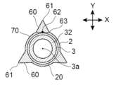
図2に示す通り、バルーン2は、収縮状態で羽根形状である羽根形状部70を有し、且つ外側面に突出部60を有している。羽根形状部70は、バルーン2が収縮している状態において、バルーン2の内表面のうち、互いに重なり合う部分を有することが好ましい。また羽根形状部70は例えば頂部71を折り目として折り畳めるように形成されていることが好ましい。
As shown in FIG. 2, the balloon 2 has wing-shaped portions 70 that are wing-shaped in a contracted state, and has projections 60 on the outer surface. The vane-shaped portions 70 preferably have portions of the inner surface of the balloon 2 that overlap each other when the balloon 2 is deflated. Further, it is preferable that the vane-shaped portion 70 is formed so as to be foldable, for example, using the top portion 71 as a crease.
突出部60は、バルーン2の外側面に設けられているものである。石灰化病変等においてバルーン2を拡張することにより、突出部60が、例えば石灰化して硬化した病変部に亀裂を入れて狭窄部を拡張させることができる。
The projecting portion 60 is provided on the outer surface of the balloon 2 . By expanding the balloon 2 in a calcified lesion or the like, the protrusion 60 can, for example, crack a calcified and hardened lesion to dilate the stricture.
突出部60は、図1、図2に示すように羽根形状部70以外の部分に位置することが好ましい。突出部60が羽根形状部70以外の部分に位置することにより、収縮状態のバルーン2の周方向において羽根形状部70と突出部60とが異なる位置に配置され、バルーン2の羽根形状部70を折り畳んだ際にバルーン2の外径を小さくすることができる。
The projecting portion 60 is preferably located in a portion other than the blade-shaped portion 70 as shown in FIGS. By locating the projecting portion 60 at a portion other than the vane-shaped portion 70, the vane-shaped portion 70 and the projecting portion 60 are arranged at different positions in the circumferential direction of the deflated balloon 2, and the vane-shaped portion 70 of the balloon 2 is arranged. The outer diameter of the balloon 2 can be reduced when folded.
突出部60の径方向の最大長さは、バルーン本体20の膜厚の1.2倍以上が好ましく、より好ましくは1.5倍以上、さらに好ましくは2倍以上である。これにより、狭窄部に適度な深さの切り込みを入れ易くなる。一方、突出部60の径方向の最大長さは、100倍以下、50倍以下、30倍以下、または10倍以下であってもよい。また、突出部60の径方向の長さは、軸方向aにおいて異なっていてもよく、同じであってもよい。
The maximum radial length of the projecting portion 60 is preferably 1.2 times or more, more preferably 1.5 times or more, and still more preferably 2 times or more the film thickness of the balloon body 20 . As a result, it becomes easier to cut into the narrowed portion to an appropriate depth. On the other hand, the maximum radial length of the protrusion 60 may be 100 times or less, 50 times or less, 30 times or less, or 10 times or less. Moreover, the radial length of the projecting portion 60 may be different or the same in the axial direction a.
突出部60のA-A断面、B-B断面における形状は、三角形状、台形状、半円状、または半楕円状であることが好ましい。また当該断面形状は、シャフト3の中心3aから突出部60の頂部61に向かう方向に先細りとなるテーパー部を一つのみ有する1段テーパー形状であることがより好ましい。
The shape of the protruding portion 60 in cross section AA and cross section BB is preferably triangular, trapezoidal, semicircular, or semielliptical. More preferably, the cross-sectional shape is a single-step tapered shape having only one tapered portion that tapers in the direction from the center 3 a of the shaft 3 toward the top portion 61 of the projecting portion 60 .
図1に示すように、突出部60は、直管部23に設けられていることが好ましく、近位側テーパー部22、直管部23、及び遠位側テーパー部24に設けられていることがより好ましく、近位側固定部21、近位側テーパー部22、直管部23、遠位側テーパー部24、及び遠位側固定部25に設けられていることが更に好ましい。突出部60の数は1つであってもよいし、複数であってもよい。突出部60が周方向に複数設けられている場合は、複数の突出部60が周方向に離隔していることが好ましく、周方向に等間隔に配されていることがより好ましい。
As shown in FIG. 1 , the protruding portion 60 is preferably provided on the straight tube portion 23, and is provided on the proximal side taper portion 22, the straight tube portion 23, and the distal side taper portion 24. is more preferable, and it is even more preferable to be provided in the proximal fixing portion 21 , the proximal tapered portion 22 , the straight tube portion 23 , the distal tapered portion 24 and the distal fixing portion 25 . The number of protrusions 60 may be one or plural. When a plurality of projecting portions 60 are provided in the circumferential direction, the plurality of projecting portions 60 are preferably spaced apart in the circumferential direction, and more preferably arranged at equal intervals in the circumferential direction.
突出部60は、図1に示すように、バルーン本体20の外側面において軸方向aに延在していることが好ましい。これにより狭窄部を真っ直ぐに切開し易くすることができる。また図示していないが、突出部60は軸方向aにおいて周方向の異なる位置、例えばバルーン本体20の外側面を周方向に周回するように螺旋状に配されていてもよい。これにより狭窄部を斜めに切開することができる。
The projecting portion 60 preferably extends in the axial direction a on the outer surface of the balloon body 20, as shown in FIG. This makes it easier to incise the constriction straight. Although not shown, the projecting portion 60 may be arranged at different positions in the axial direction a in the circumferential direction, for example, spirally around the outer surface of the balloon body 20 in the circumferential direction. As a result, the constriction can be obliquely incised.
図2のような直管部23の軸方向aと垂直な方向の断面において、突出部60の頂部61からシャフト3の中心3aに向かう方向をY方向、Y方向に垂直な方向をX方向としたとき、レーザーラマン分光法により測定される断面の各部における散乱強度が下記式(1)を満たす。
I2>I1 ・・・(1)
[式中、I1は、突出部60の頂部61におけるIa/Ibの値であり、I2は、突出部60の基端部の周方向の中心部62におけるIa/Ibの値である。
但し、Iaは、X方向の波数1640±10cm-1のピーク強度の、Y方向の波数1640±10cm-1のピーク強度に対する割合であり、Ibは、X方向の波数1440±10cm-1のピーク強度の、Y方向の波数1440±10cm-1のピーク強度に対する割合である。] In the cross section perpendicular to the axial direction a of thestraight pipe portion 23 as shown in FIG. Then, the scattering intensity at each portion of the cross section measured by laser Raman spectroscopy satisfies the following formula (1).
I 2 >I 1 (1)
[In the formula, I1 is the value of Ia/Ib at the top 61 of theprojection 60 and I2 is the value of Ia/Ib at the center 62 of the proximal end of the projection 60 in the circumferential direction.
However, Ia is the ratio of the peak intensity at the wave number of 1640 ± 10 cm in the X direction to the peak intensity at the wave number of 1640 ± 10 cm in the Y direction, and Ib is the peak at the wave number of 1440 ± 10 cm in the X direction. It is the ratio of the intensity to the peak intensity at wave number 1440±10 cm −1 in the Y direction. ]
I2>I1 ・・・(1)
[式中、I1は、突出部60の頂部61におけるIa/Ibの値であり、I2は、突出部60の基端部の周方向の中心部62におけるIa/Ibの値である。
但し、Iaは、X方向の波数1640±10cm-1のピーク強度の、Y方向の波数1640±10cm-1のピーク強度に対する割合であり、Ibは、X方向の波数1440±10cm-1のピーク強度の、Y方向の波数1440±10cm-1のピーク強度に対する割合である。] In the cross section perpendicular to the axial direction a of the
I 2 >I 1 (1)
[In the formula, I1 is the value of Ia/Ib at the top 61 of the
However, Ia is the ratio of the peak intensity at the wave number of 1640 ± 10 cm in the X direction to the peak intensity at the wave number of 1640 ± 10 cm in the Y direction, and Ib is the peak at the wave number of 1440 ± 10 cm in the X direction. It is the ratio of the intensity to the peak intensity at wave number 1440±10 cm −1 in the Y direction. ]
レーザーラマン分光法により得られるスペクトルのうち、波数1640±10cm-1のピークはC=O構造に由来するピークであり、波数1440±10cm-1のピークはC-H構造に由来するピークである。当該レーザーラマン分光法に基づいて算出されるIa/Ibの値が大きい程、バルーン2内の高次構造の配向が大きくなる。そのため、上記式(1)のようにI2がI1よりも大きいことにより、突出部60の基端部の周方向の中心部62は、高次構造の配向が大きくなって剛性に優れる部分になる結果、突出部60がバルーン2内部に埋もれ難くなる。そのためI2はI1の1.5倍以上であることが好ましく、2.5倍以上であることがより好ましく、3.5倍以上であることが更に好ましく、4.0倍以上であることが更により好ましい。一方、I2はI1の10倍以下であることが好ましい。これにより、バルーン2を製造し易くすることができる。I2はI1の8倍以下であることがより好ましく、6倍以下であることが更に好ましく、5倍以下であることが更により好ましい。なお図2中、破線は突出部60の基端縁を示す仮想線分であり、突出部60の中心部62は、当該仮想線分上であって、当該仮想線分の両端から仮想線分の長さの1/4超離れた領域に位置することが好ましく、仮想線分の中心点に位置することがより好ましい。
Among the spectra obtained by laser Raman spectroscopy, the peak at a wave number of 1640 ± 10 cm -1 is a peak derived from the C=O structure, and the peak at a wave number of 1440 ± 10 cm -1 is a peak derived from the CH structure. . The greater the value of Ia/Ib calculated based on the laser Raman spectroscopy, the greater the orientation of the higher-order structure within the balloon 2 . Therefore, since I2 is larger than I1 as in the above formula (1), the central portion 62 in the circumferential direction of the base end portion of the protruding portion 60 has a high-order structure orientation and excellent rigidity. As a result, the projecting portion 60 is less likely to be buried inside the balloon 2 . Therefore, I2 is preferably at least 1.5 times I1 , more preferably at least 2.5 times, even more preferably at least 3.5 times, and at least 4.0 times. is even more preferred. On the other hand, I2 is preferably 10 times or less than I1 . This makes it easier to manufacture the balloon 2 . I 2 is more preferably 8 times or less than I 1 , still more preferably 6 times or less, and even more preferably 5 times or less. In FIG. 2, the dashed line is a virtual line segment indicating the base edge of the protrusion 60, and the central portion 62 of the protrusion 60 is on the virtual line segment and extends from both ends of the virtual line segment. It is preferably located in a region more than 1/4 of the length of , and more preferably located at the center point of the imaginary line segment.
バルーンカテーテル1は、レーザーラマン分光法により測定される断面の各部における散乱強度が下記式(2)の大小関係を満たすことが好ましい。
I3>I1 ・・・(2)
[式中、I1は上記と同じであり、I3は、突出部60の基端部の周方向の一端部63におけるIa/Ibの値である。但し、Ia、Ibは上記と同じである。] In theballoon catheter 1, the scattering intensity at each part of the cross section measured by laser Raman spectroscopy preferably satisfies the magnitude relationship of the following formula (2).
I 3 >I 1 (2)
[In the formula, I1 is the same as above, and I3 is the value of Ia/Ib at onecircumferential end 63 of the proximal end of the protrusion 60 . However, Ia and Ib are the same as above. ]
I3>I1 ・・・(2)
[式中、I1は上記と同じであり、I3は、突出部60の基端部の周方向の一端部63におけるIa/Ibの値である。但し、Ia、Ibは上記と同じである。] In the
I 3 >I 1 (2)
[In the formula, I1 is the same as above, and I3 is the value of Ia/Ib at one
I3がI1よりも大きいことにより、突出部60の基端部の周方向の一端部63は、高次構造の配向が大きくなるため、剛性に優れる部分になる結果、突出部60が一層、バルーン2内部に埋もれ難くなる。I3はI1の1.5倍以上であることが好ましく、2.0倍以上であることがより好ましく、2.5倍以上であることが更に好ましい。一方、I3がI1の6倍以下であることが好ましい。これにより、バルーン2を製造し易くすることができる。I3はI1の5倍以下であることがより好ましく、4倍以下であることが更に好ましい。なお突出部60の基端部の周方向の両端部において、上記式(2)を満たすことがより好ましい。なお図2中、破線は突出部60の基端縁を示す仮想線分であり、突出部60の一端部63は、当該仮想線分上であって、当該仮想線分の一端から仮想線分の長さの1/4以内の領域に位置することが好ましく、当該仮想線分の一端に位置することがより好ましい。
Since I3 is larger than I1 , one circumferential end portion 63 of the proximal end portion of the protrusion 60 has a higher orientation of the higher-order structure, so that it becomes a portion having excellent rigidity. , it becomes difficult to be buried inside the balloon 2 . I3 is preferably at least 1.5 times I1 , more preferably at least 2.0 times, and even more preferably at least 2.5 times. On the other hand, it is preferable that I3 is less than or equal to 6 times I1 . This makes it easier to manufacture the balloon 2 . I 3 is more preferably 5 times or less than I 1 , and even more preferably 4 times or less. It is more preferable that both circumferential ends of the proximal end of the projecting portion 60 satisfy the above formula (2). In FIG. 2, the dashed line is a virtual line segment indicating the base edge of the protrusion 60, and one end 63 of the protrusion 60 is on the virtual line segment and extends from one end of the virtual line segment to the virtual line segment. It is preferably positioned within a quarter of the length of , and more preferably positioned at one end of the imaginary line segment.
上記断面において、羽根形状部70の頂部71からシャフト3の中心3aに向かう方向をX4方向、X4方向と垂直な方向をY4方向としたとき、レーザーラマン分光法により測定される断面の各部における散乱強度が下記式(3)の大小関係を満たすことが好ましい。
I2>I4 ・・・(3)
[式中、I2は上記と同じであり、I4は羽根形状部70の頂部71におけるIc/Idの値である。
但し、Icは、X4方向の波数1640±10cm-1のピーク強度の、Y4方向の波数1640±10cm-1のピーク強度に対する割合であり、Idは、X4方向の波数1440±10cm-1のピーク強度の、Y4方向の波数1440±10cm-1のピーク強度に対する割合である。] In the above cross section, when the direction from thetop portion 71 of the blade-shaped portion 70 to the center 3a of the shaft 3 is the X4 direction, and the direction perpendicular to the X4 direction is the Y4 direction, the cross section measured by laser Raman spectroscopy. It is preferable that the scattering intensity at each portion satisfies the magnitude relationship of the following formula (3).
I 2 >I 4 (3)
[where I 2 is the same as above and I 4 is the value of Ic/Id at the top 71 of thevane profile 70 .
where Ic is the ratio of the peak intensity at wave number 1640±10 cm −1 in X4 direction to the peak intensity at wave number 1640±10 cm −1 in Y4 direction, and Id is the wave number 1440±10 cm −1 in X4 direction . is the ratio of the peak intensity of 1 to the peak intensity of wave number 1440±10 cm −1 in the Y4 direction. ]
I2>I4 ・・・(3)
[式中、I2は上記と同じであり、I4は羽根形状部70の頂部71におけるIc/Idの値である。
但し、Icは、X4方向の波数1640±10cm-1のピーク強度の、Y4方向の波数1640±10cm-1のピーク強度に対する割合であり、Idは、X4方向の波数1440±10cm-1のピーク強度の、Y4方向の波数1440±10cm-1のピーク強度に対する割合である。] In the above cross section, when the direction from the
I 2 >I 4 (3)
[where I 2 is the same as above and I 4 is the value of Ic/Id at the top 71 of the
where Ic is the ratio of the peak intensity at wave number 1640±10 cm −1 in X4 direction to the peak intensity at wave number 1640±10 cm −1 in Y4 direction, and Id is the wave number 1440±10 cm −1 in X4 direction . is the ratio of the peak intensity of 1 to the peak intensity of wave number 1440±10 cm −1 in the Y4 direction. ]
当該レーザーラマン分光法に基づいて算出されるIa/Ib、Ic/Idの値が大きい程、バルーン2内の高次構造の配向が大きくなる。そのためI2がI4よりも大きいことにより、突出部60の基端部の周方向の中心部62は、高次構造の配向が大きくなり剛性に優れる部分になる結果、突出部60がバルーン2内部に埋もれ難くなる。I2はI4の1.01倍以上であることが好ましく、1.02倍以上であることがより好ましく、1.03倍以上であることが更に好ましい。一方、I2はI4の3.0倍以下であることが好ましい。これにより、羽根形状部70の頂部71近傍の剛性を向上することができる。I2はI4の2.0倍以下であることがより好ましく、1.5倍以下であることが更に好ましく、1.2倍以下であることが更により好ましい。
The higher the values of Ia/Ib and Ic/Id calculated based on the laser Raman spectroscopy, the higher the orientation of the higher-order structure in the balloon 2 . Therefore, when I2 is larger than I4 , the center portion 62 in the circumferential direction of the proximal end portion of the protrusion 60 has a higher orientation of the higher-order structure and becomes a portion having excellent rigidity. It becomes difficult to be buried inside. I 2 is preferably at least 1.01 times I 4 , more preferably at least 1.02 times, even more preferably at least 1.03 times. On the other hand, I2 is preferably 3.0 times or less than I4 . Thereby, the rigidity of the vane-shaped portion 70 near the top portion 71 can be improved. I 2 is more preferably 2.0 times or less I 4 , still more preferably 1.5 times or less, and even more preferably 1.2 times or less.
バルーンカテーテル1は、レーザーラマン分光法により測定される断面の各部における散乱強度が下記式(4)の大小関係を満たすことが好ましい。
I2>I3 ・・・(4)
[式中、I2、I3は上記と同じである。] In theballoon catheter 1, it is preferable that the scattering intensity at each part of the cross section measured by laser Raman spectroscopy satisfies the magnitude relationship of the following formula (4).
I 2 >I 3 (4)
[In the formula, I 2 and I 3 are the same as above. ]
I2>I3 ・・・(4)
[式中、I2、I3は上記と同じである。] In the
I 2 >I 3 (4)
[In the formula, I 2 and I 3 are the same as above. ]
I2がI3よりも大きいことにより、バルーン拡張時に突出部60を病変部に食い込ませ易くすることができる。そのため、I2はI3の1.1倍以上であることが好ましく、1.2倍以上であることがより好ましく、1.4倍以上であることが更に好ましい。一方、I2がI3の2.5倍以下であることが好ましい。これにより、突出部60の基端部の周方向の一端部63が突出部60を支持し易くすることができる。I3はI2の2.0倍以下であることがより好ましく、1.8倍以下であることが更に好ましい。なお突出部60の基端部の周方向の両端部において、上記式(4)を満たすことがより好ましい。
When I 2 is larger than I 3 , the projecting portion 60 can be easily bitten into the lesion during balloon expansion. Therefore, I2 is preferably at least 1.1 times I3 , more preferably at least 1.2 times, even more preferably at least 1.4 times. On the other hand, it is preferable that I2 is 2.5 times or less than I3 . As a result, the one end portion 63 in the circumferential direction of the proximal end portion of the projecting portion 60 can easily support the projecting portion 60 . I 3 is more preferably 2.0 times or less than I 2 and even more preferably 1.8 times or less. In addition, it is more preferable that both circumferential ends of the proximal end portion of the projecting portion 60 satisfy the above formula (4).
上記式(1)~(4)については、軸方向aにおける直管部23の全域で満たす必要はなく、剛性に優れる部分を適宜設けてもよい。例えば、軸方向aにおける直管部23の中点、軸方向aにおける直管部23の一端から直管部23の長さの1/3の距離の点、軸方向aにおける直管部23の一端から直管部23の長さの1/4の距離の点などを含む領域において上記式(1)~(4)を満たすことが好ましい。これにより、直管部23の中央や先端寄り、後端寄りなど所望の位置で剛性に優れる部分を設けることが可能となる。また上記式(1)~(4)を満たす領域の長さについても特に限定されないが、軸方向aにおける直管部23の長さの1/18以上が好ましく、1/15以上がより好ましく、1/12以上が更に好ましい。式(1)~(4)とは、式(1);式(1)と式(2);式(1)と式(3);式(1)と式(4);式(1)と式(2)と式(3);式(1)と式(2)と式(4);式(1)と式(3)と式(4);式(1)と式(2)と式(3)と式(4)のいずれかを意味する。上記領域において、式(1);式(1)と式(2);式(1)と式(3);または式(1)と式(2)と式(3)を満たすことが好ましい。
The above expressions (1) to (4) do not need to be satisfied in the entire straight pipe portion 23 in the axial direction a, and a portion having excellent rigidity may be provided as appropriate. For example, the midpoint of the straight pipe portion 23 in the axial direction a, the point 1/3 of the length of the straight pipe portion 23 from one end of the straight pipe portion 23 in the axial direction a, the straight pipe portion 23 in the axial direction a. It is preferable that the above formulas (1) to (4) are satisfied in a region including a point at a distance of 1/4 of the length of the straight tube portion 23 from one end. Thereby, it is possible to provide a portion having excellent rigidity at a desired position such as the center, near the tip, or near the rear end of the straight pipe portion 23 . The length of the region that satisfies the above formulas (1) to (4) is also not particularly limited, but is preferably 1/18 or more, more preferably 1/15 or more, of the length of the straight tube portion 23 in the axial direction a. 1/12 or more is more preferable. Formulas (1) to (4) are Formula (1); Formula (1) and Formula (2); Formula (1) and Formula (3); Formula (1) and Formula (4); Formula (1) and formula (2) and formula (3); formula (1) and formula (2) and formula (4); formula (1) and formula (3) and formula (4); formula (1) and formula (2) and either of equations (3) and (4). Formula (1) and Formula (2); Formula (1) and Formula (3); or Formula (1) and Formula (2) and Formula (3) are preferably satisfied in the above region.
バルーン2は、樹脂、ゴム、またはこれらの混合物を含むことが好ましく、樹脂、ゴム、またはこれらの混合物からなることがより好ましい。樹脂としては、ポリアミド、ポリエーテルブロックアミド共重合体等のポリアミドエラストマー等のポリアミド樹脂;ポリエチレンテレフタレート、ポリエステルエラストマー等のポリエステル樹脂;ポリウレタン、ポリウレタンエラストマー等のポリウレタン樹脂;等のC-H単位とC=O単位を含有する樹脂が好ましい。またこれらの樹脂のうちエラストマーがより好ましい。バルーン2は、その他の樹脂を含んでいてもよく、例えばポリフェニレンサルファイド樹脂、フッ素樹脂、シリコーン樹脂、ポリエチレン、ポリプロピレン、エチレン-プロピレン共重合体等のポリオレフィン樹脂等の樹脂が挙げられる。ゴムとしては、ラテックスゴム等の天然ゴム等が挙げられる。これらは1種のみを用いてもよく、2種以上を併用してもよい。これらのうち、ポリアミド樹脂、ポリエステル樹脂、ポリウレタン樹脂、またはこれらの混合物がより好ましく、ポリアミド樹脂、ポリウレタン樹脂、またはこれらの混合物が更に好ましく、ポリアミド樹脂が更により好ましく、ポリエーテルブロックアミド共重合体が特に好ましい。これにより、高次構造の配向が大きい部分を形成し易くすることができる。
The balloon 2 preferably contains resin, rubber, or a mixture thereof, and is more preferably made of resin, rubber, or a mixture thereof. Examples of resins include polyamide resins such as polyamide elastomers such as polyamides and polyether block amide copolymers; polyester resins such as polyethylene terephthalate and polyester elastomers; polyurethane resins such as polyurethanes and polyurethane elastomers; Resins containing O units are preferred. Elastomers are more preferred among these resins. The balloon 2 may contain other resins such as polyphenylene sulfide resins, fluororesins, silicone resins, and polyolefin resins such as polyethylene, polypropylene, and ethylene-propylene copolymers. Examples of rubber include natural rubber such as latex rubber. These may use only 1 type and may use 2 or more types together. Of these, polyamide resins, polyester resins, polyurethane resins, or mixtures thereof are more preferred, polyamide resins, polyurethane resins, or mixtures thereof are more preferred, polyamide resins are even more preferred, and polyether block amide copolymers are preferred. Especially preferred. As a result, it is possible to easily form a portion having a high orientation of the higher-order structure.
突出部60は、バルーン本体20と同一材料から構成されていることが好ましい。これにより、バルーン2の柔軟性を維持しながら、突出部60がバルーン本体20の外面を傷付けにくくすることができる。バルーン本体20と突出部60とは一体成形されていることが好ましい。これにより、バルーン本体20からの突出部60の脱落を防ぐことができる。
The projecting portion 60 is preferably made of the same material as the balloon body 20 . As a result, while maintaining the flexibility of the balloon 2 , the projecting portion 60 is less likely to damage the outer surface of the balloon body 20 . It is preferable that the balloon main body 20 and the projecting portion 60 are integrally molded. This can prevent the projecting portion 60 from falling off from the balloon body 20 .
バルーン2は、例えば図4に示すような軸方向aに延在する肉厚部220を有し、且つ樹脂から構成されるパリソン200を用いて製造することができる。例えば、パリソン200を金型の内腔内に配置しブロー成形することにより製造することができる。詳細にはバルーン2は、例えば、パリソン200を金型の内腔に配置して、金型の所定の形状の溝にパリソン200の肉厚部220を入り込ませ、パリソン200の内腔210に流体を導入して、加熱しながらパリソン200を膨張させることで形成することができる。突出部60の幅や高さは、パリソン200の肉厚部220の厚みや金型の溝の深さや形状で調節することができる。流体として空気、窒素、水等が挙げられる。ブロー成形の際には、樹脂のガラス転移温度以上の温度でパリソン200を加熱することが好ましい。なお当該膨張前にパリソン200を軸方向aに延伸してもよい。パリソン200を膨張させるステップは、1回のみ行ってもよく、複数回行ってもよい。膨張工程を複数回行う場合、膨張毎に異なる金型を使用してもよい。
The balloon 2 can be manufactured, for example, using a parison 200 made of resin and having a thick portion 220 extending in the axial direction a as shown in FIG. For example, the parison 200 can be manufactured by placing it in the lumen of a mold and blow molding it. More specifically, the balloon 2 is prepared, for example, by placing the parison 200 in the lumen of a mold, allowing the thickened portion 220 of the parison 200 to enter a groove of a predetermined shape in the mold, and allowing the fluid to enter the lumen 210 of the parison 200 . can be formed by introducing and expanding the parison 200 while heating. The width and height of the projecting portion 60 can be adjusted by the thickness of the thick portion 220 of the parison 200 and the depth and shape of the mold groove. Examples of fluids include air, nitrogen, water, and the like. During blow molding, it is preferable to heat the parison 200 at a temperature equal to or higher than the glass transition temperature of the resin. Note that the parison 200 may be stretched in the axial direction a before the expansion. The step of inflating the parison 200 may be performed only once or may be performed multiple times. If the expansion step is performed multiple times, a different mold may be used for each expansion.
パリソン200の肉厚部220は、図5に示すように内腔210から肉厚部220の頂部に向かう方向に先細りとなる第1テーパー部221と、第1テーパー部221よりも肉厚部220の頂部側であって、内腔210から肉厚部220の頂部に向かう方向に先細りとなる第2テーパー部222と、を有していることが好ましい。このようにパリソン200が2段テーパー部を有していることにより、ブロー成形の際に第1テーパー部221に張力がかかり易くなるため、ブロー成形により得られる突出部60の基端部の中心部62近傍の配向を大きくすることができる。なお、図5では全長にわたって2段テーパー部を有するパリソンを示したが、パリソンの一部分に2段テーパー部を有するパリソンをしてもよい。これにより、直管部23の所望の箇所において剛性に優れる部分を設けることが可能となる。
The thick portion 220 of the parison 200 includes, as shown in FIG. and a second tapered portion 222 that tapers in a direction from the lumen 210 toward the top of the thickened portion 220 . Since the parison 200 has the two-step tapered portion, tension is easily applied to the first tapered portion 221 during blow molding. The orientation near the portion 62 can be increased. Although FIG. 5 shows a parison having a two-step tapered portion over the entire length, a parison having a two-step tapered portion in a portion of the parison may be used. Thereby, it becomes possible to provide a portion having excellent rigidity at a desired portion of the straight pipe portion 23 .
ブロー成形を行う際には、パリソン200の2段テーパー形状を消失させて、1段テーパー形状の突出部60を形成することが好ましい。これにより突出部60の基端部の中心部62近傍の配向を一層、大きくすることができる。なおパリソン200の2段テーパー形状を消失させる方法としては、パリソン200の第1テーパー部221を金型の内腔内の溝にはめ込まず、第2テーパー部222のみを溝にはめ込んでからブロー成形を行えばよい。なお当該溝はV型溝であることが好ましい。
When performing blow molding, it is preferable to eliminate the two-step tapered shape of the parison 200 and form the one-step tapered protruding portion 60 . This makes it possible to further increase the orientation of the protruding portion 60 in the vicinity of the central portion 62 of the base end thereof. As a method for eliminating the two-step tapered shape of the parison 200, the first tapered portion 221 of the parison 200 is not fitted into the groove in the inner cavity of the mold, and only the second tapered portion 222 is fitted into the groove before blow molding. should be done. Note that the groove is preferably a V-shaped groove.
第1テーパー部221の基端部の幅W1は、第2テーパー部の基端部222の幅W2の1.5倍以上であることが好ましく、2.0倍以上であることがより好ましい。これにより、ブロー成形の際に第1テーパー部221に張力をかけ易くすることができる。一方、当該倍率は10倍以下、または5倍以下であってもよい。
The width W1 of the base end portion of the first taper portion 221 is preferably 1.5 times or more, more preferably 2.0 times or more, the width W2 of the base end portion 222 of the second taper portion. This makes it easier to apply tension to the first tapered portion 221 during blow molding. On the other hand, the magnification may be 10 times or less, or 5 times or less.
第1テーパー部221の高さh1は、第2テーパー部222の高さh2の0.9倍以下であることが好ましく、0.8倍以下であることがより好ましい。これにより、ブロー成形の際に第1テーパー部221に張力をかけ易くすることができる。一方、当該倍率は0.1倍以上、または0.2倍以上であってもよい。
The height h1 of the first taper portion 221 is preferably 0.9 times or less, and more preferably 0.8 times or less, the height h2 of the second taper portion 222. This makes it easier to apply tension to the first tapered portion 221 during blow molding. On the other hand, the magnification may be 0.1 times or more, or 0.2 times or more.
シャフト3は、樹脂、ゴム、またはこれらの混合物を含むことが好ましい。樹脂、ゴムとして、ポリアミド樹脂、ポリエステル樹脂、ポリウレタン樹脂、ポリオレフィン樹脂、フッ素樹脂、塩化ビニル樹脂、シリコーン樹脂、天然ゴム等が挙げられる。これらは1種のみを用いてもよく、2種以上を併用してもよい。これらのうち、ポリアミド樹脂、ポリオレフィン樹脂、フッ素樹脂、これらの混合物、またはこれらの樹脂層を積層した積層体を含むことが好ましい。これにより、シャフト3の表面の滑り性を高めつつ、バルーンカテーテル1の体腔内での挿通性を向上させることができる。なおバルーン2をシャフト3へ固定する方法としては、接着剤による接合、溶着、リング状部材をかしめて固定する方法等が挙げられる。またシャフト3は、金属管、単線または複数の線材、撚線の線材等を含んでいてもよい。
The shaft 3 preferably contains resin, rubber, or a mixture thereof. Examples of resins and rubbers include polyamide resins, polyester resins, polyurethane resins, polyolefin resins, fluororesins, vinyl chloride resins, silicone resins, and natural rubbers. These may use only 1 type and may use 2 or more types together. Among these, it is preferable to include a polyamide resin, a polyolefin resin, a fluororesin, a mixture thereof, or a laminate obtained by laminating these resin layers. As a result, it is possible to improve the insertability of the balloon catheter 1 in the body cavity while improving the lubricity of the surface of the shaft 3 . Methods for fixing the balloon 2 to the shaft 3 include bonding with an adhesive, welding, and fixing by caulking a ring-shaped member. The shaft 3 may also include a metal tube, a single wire or multiple wires, a stranded wire, or the like.
図1に示すように、バルーンカテーテル1は、シャフト3の近位側にハブ4を有していてもよい。ハブ4は、バルーン2の内部に供給される流体の流路と連通した流体注入部7、ガイドワイヤの挿通路と連通したガイドワイヤ挿入部5等を有していてもよい。これにより、バルーン2の内部に流体を供給してバルーン2を拡張させる操作や、ガイドワイヤに沿ってバルーン2を治療部位まで送達する操作を容易に行うことができる。バルーンカテーテル1は、図1に示したようなガイドワイヤがシャフト3の遠位側から近位側にわたって挿通されるいわゆるオーバーザワイヤ型であることが好ましいが、シャフト3の遠位側から近位側に至る途中までガイドワイヤを挿通するいわゆるラピッドエクスチェンジ型であってもよい。
The balloon catheter 1 may have a hub 4 on the proximal side of the shaft 3, as shown in FIG. The hub 4 may have a fluid injection section 7 in communication with the flow path of the fluid supplied to the inside of the balloon 2, a guide wire insertion section 5 in communication with the insertion passage of the guide wire, and the like. This makes it possible to easily perform an operation to expand the balloon 2 by supplying fluid to the inside of the balloon 2 and an operation to deliver the balloon 2 to the treatment site along the guidewire. The balloon catheter 1 is preferably of a so-called over-the-wire type in which a guide wire as shown in FIG. It may be a so-called rapid exchange type in which the guide wire is inserted halfway to the end.
本願は、2021年11月9日に出願された日本国特許出願第2021-182760号に基づく優先権の利益を主張するものである。2021年11月9日に出願された日本国特許出願第2021-182760号の明細書の全内容が、本願に参考のため援用される。
This application claims the benefit of priority based on Japanese Patent Application No. 2021-182760 filed on November 9, 2021. The entire contents of the specification of Japanese Patent Application No. 2021-182760 filed on November 9, 2021 are incorporated herein by reference.
以下、実施例を挙げて本発明をより具体的に説明するが、本発明は下記実施例によって制限されず、前・後記の趣旨に適合し得る範囲で変更を加えて実施することも可能であり、それらはいずれも本発明の技術的範囲に包含される。
Hereinafter, the present invention will be described in more detail with reference to examples, but the present invention is not limited to the following examples, and it is possible to implement it by adding changes within the scope that can conform to the gist of the above and later descriptions. All of them are included in the technical scope of the present invention.
[実施例1]
ARKEMA社製のポリアミドエラストマー(PEBAX(登録商標)7233)を用いた押出成形により、図4、図5に示すような、内径:0.50mm、外径:1.00mm、軸方向の長さ:300mmの管状部と、肉厚部220とを有するバルーン作製用のチューブであるパリソン200を作製した。肉厚部220の各寸法は以下の通りである。
第1テーパー部の基端部の幅(W1):1.0mm
第2テーパー部の基端部の幅(W2):0.5mm
第1テーパー部の高さ(h1):0.2mm
第2テーパー部の高さ(h2):0.5mm
軸方向aの長さ:35mm [Example 1]
By extrusion molding using a polyamide elastomer (PEBAX (registered trademark) 7233) manufactured by ARKEMA, as shown in FIGS. Aparison 200, which is a tube for manufacturing a balloon having a tubular portion of 300 mm and a thick portion 220, was manufactured. Each dimension of the thick portion 220 is as follows.
Width (W1) of base end of first tapered portion: 1.0 mm
Width (W2) of the proximal end of the second tapered portion: 0.5 mm
Height of first taper portion (h1): 0.2 mm
Height of second tapered portion (h2): 0.5 mm
Length in axial direction a: 35 mm
ARKEMA社製のポリアミドエラストマー(PEBAX(登録商標)7233)を用いた押出成形により、図4、図5に示すような、内径:0.50mm、外径:1.00mm、軸方向の長さ:300mmの管状部と、肉厚部220とを有するバルーン作製用のチューブであるパリソン200を作製した。肉厚部220の各寸法は以下の通りである。
第1テーパー部の基端部の幅(W1):1.0mm
第2テーパー部の基端部の幅(W2):0.5mm
第1テーパー部の高さ(h1):0.2mm
第2テーパー部の高さ(h2):0.5mm
軸方向aの長さ:35mm [Example 1]
By extrusion molding using a polyamide elastomer (PEBAX (registered trademark) 7233) manufactured by ARKEMA, as shown in FIGS. A
Width (W1) of base end of first tapered portion: 1.0 mm
Width (W2) of the proximal end of the second tapered portion: 0.5 mm
Height of first taper portion (h1): 0.2 mm
Height of second tapered portion (h2): 0.5 mm
Length in axial direction a: 35 mm
次にパリソン200を金型の内腔に配置した。当該金型は、バルーン2の各部に対応する部分において、下記の寸法を有する内腔とV型溝を備えるものである。
・近位側固定部21を形成する部分の内腔
直径:1.0mm
軸方向の長さ:5mm
・近位側テーパー部22を形成する部分の内腔
近位端の直径:1.0mm
遠位端の直径:2.75mm
軸方向の長さ:5mm
・直管部23を形成する部分の内腔
直径:2.75mm
軸方向の長さ:15mm
・遠位側テーパー部24を形成する部分の内腔
近位端の直管:2.75mm
遠位端の直径:1.0mm
軸方向の長さ:5mm
・遠位側固定部25を形成する部分の内腔
直径:1.0mm
軸方向の長さ:5mm
・突出部60を形成する部分のV型溝
深さ:0.8mm
最大幅:0.5mm
軸方向の長さ: 35mm Theparison 200 was then placed in the mold cavity. The mold has lumens and V-shaped grooves having the following dimensions in the portions corresponding to the respective portions of the balloon 2 .
・Lume diameter of the part forming the proximal side fixing part 21: 1.0 mm
Axial length: 5mm
・Lume of the portion forming the proximalside taper portion 22 Diameter of the proximal end: 1.0 mm
Distal end diameter: 2.75mm
Axial length: 5mm
・Inner lumen diameter of the portion forming the straight tube portion 23: 2.75 mm
Axial length: 15mm
・Inner lumen of the portion forming the distal taperedportion 24 Straight pipe at the proximal end: 2.75 mm
Distal end diameter: 1.0 mm
Axial length: 5mm
・Lume diameter of the part forming the distal side fixing part 25: 1.0 mm
Axial length: 5mm
・ V-shaped groove depth of the part forming the protrusion 60: 0.8 mm
Maximum width: 0.5mm
Axial length: 35mm
・近位側固定部21を形成する部分の内腔
直径:1.0mm
軸方向の長さ:5mm
・近位側テーパー部22を形成する部分の内腔
近位端の直径:1.0mm
遠位端の直径:2.75mm
軸方向の長さ:5mm
・直管部23を形成する部分の内腔
直径:2.75mm
軸方向の長さ:15mm
・遠位側テーパー部24を形成する部分の内腔
近位端の直管:2.75mm
遠位端の直径:1.0mm
軸方向の長さ:5mm
・遠位側固定部25を形成する部分の内腔
直径:1.0mm
軸方向の長さ:5mm
・突出部60を形成する部分のV型溝
深さ:0.8mm
最大幅:0.5mm
軸方向の長さ: 35mm The
・Lume diameter of the part forming the proximal side fixing part 21: 1.0 mm
Axial length: 5mm
・Lume of the portion forming the proximal
Distal end diameter: 2.75mm
Axial length: 5mm
・Inner lumen diameter of the portion forming the straight tube portion 23: 2.75 mm
Axial length: 15mm
・Inner lumen of the portion forming the distal tapered
Distal end diameter: 1.0 mm
Axial length: 5mm
・Lume diameter of the part forming the distal side fixing part 25: 1.0 mm
Axial length: 5mm
・ V-shaped groove depth of the part forming the protrusion 60: 0.8 mm
Maximum width: 0.5mm
Axial length: 35mm
当該金型を用いて、パリソン200に対して、100℃で二軸延伸ブロー成形を行ってバルーン2を作製した。次いでバルーン2の直管部23をカットして、得られた試料を樹脂に包埋後、ライカ製の凍結ウルトラミクロトーム(UC6)を用いて観察用断面を作製した。次いで、ラマン分光装置を用いて、突出部60の頂部61、基端部の周方向の中心部62、基端部の周方向の一端部63、羽根形状部70の頂部71の各部におけるX方向とY方向の波数1630~1650cm-1の範囲内に存在するピークのピーク強度、及び波数1430~1450cm-1の範囲内に存在するピークのピーク強度を求めた。当該測定の詳細は以下の通りである。
Using the mold, the parison 200 was subjected to biaxial stretch blow molding at 100° C. to produce the balloon 2 . Next, the straight tube portion 23 of the balloon 2 was cut, and the obtained sample was embedded in resin, and then a cross section for observation was prepared using a frozen ultramicrotome (UC6) manufactured by Leica. Next, using a Raman spectroscopic device, the X direction of each of the top portion 61 of the protruding portion 60, the circumferential center portion 62 of the base end portion, the one circumferential end portion 63 of the base end portion, and the top portion 71 of the vane-shaped portion 70 is measured. and the peak intensity of the peak existing within the wave number range of 1630 to 1650 cm -1 in the Y direction, and the peak intensity of the peak existing within the wave number range of 1430 to 1450 cm -1 . Details of the measurement are as follows.
装置:ラマン分光装置(レニショー製 in ViaTM Qontor)
顕微鏡:ライカマイクロシステムズ製 DM2700型
対物レンズ:×100
ビーム径:1μm
レーザーパワー:100%
露光時間:30秒
積算回数:1回
光源:半導体レーザー 532nm Apparatus: Raman spectrometer (in Via TM Qontor manufactured by Renishaw)
Microscope: Model DM2700 manufactured by Leica Microsystems Objective lens: ×100
Beam diameter: 1 μm
Laser power: 100%
Exposure time: 30 seconds Accumulation times: 1 Light source: Semiconductor laser 532 nm
上記測定により得られたピーク強度に基づいて、上記(1)~(4)に係るI1~I4の値を算出した。その結果を表1に示す。
Based on the peak intensities obtained by the above measurements, the values of I 1 to I 4 related to (1) to ( 4 ) above were calculated. Table 1 shows the results.

表1に示す通り、バルーン2は式(1)を満たすものであった。このバルーン2をシャフトに固定して、石膏モデル内でバルーン2を拡張させたところ、直管部23の突出部60が石膏モデルに食い込んだ。更に、バルーンを収縮して石膏モデル内から抜去した後には、図6、図7に示す通り、突出部60が食い込んだ形状を確認することができた。このようにバルーン2の直管部23の突出部60は、バルーン2内部に埋もれ難く、石膏モデルに食い込み易いものであった。また上記拡張を行う前の狭窄部を模擬した石膏モデル内でバルーン2を動かした際には、突出部60の頂部61の適度な柔軟性により、引っかかることなくスムーズに挿入、抜去の操作を実施することができた。
As shown in Table 1, balloon 2 satisfied formula (1). When the balloon 2 was fixed to the shaft and expanded within the gypsum model, the projecting portion 60 of the straight tube portion 23 bit into the gypsum model. Furthermore, after deflating the balloon and removing it from the inside of the gypsum model, as shown in FIGS. As described above, the projecting portion 60 of the straight tube portion 23 of the balloon 2 is difficult to be buried inside the balloon 2 and easily bites into the gypsum model. In addition, when the balloon 2 is moved within the gypsum model simulating the stenotic part before the dilation, the appropriate flexibility of the top 61 of the protruding part 60 enables smooth insertion and withdrawal without being caught. We were able to.
[実施例2]
ARKEMA社製のポリアミドエラストマー(Rilsamid(登録商標)PA12)を用いて押出成形を行ったこと、パリソン200の第1テーパー部の基端部の幅(W1)を0.7mmとしたこと以外は実施例1と同様にして、バルーンを作製し、各部のピーク強度を求め、上記(1)~(4)に係るI1~I4の値を算出した。その結果を表2に示す。 [Example 2]
Extrusion molding was performed using a polyamide elastomer (Rilsamid (registered trademark) PA12) manufactured by ARKEMA, except that the width (W1) of the base end of the first tapered portion ofparison 200 was set to 0.7 mm. A balloon was produced in the same manner as in Example 1, the peak strength of each part was determined, and the values of I 1 to I 4 according to the above (1) to (4) were calculated. Table 2 shows the results.
ARKEMA社製のポリアミドエラストマー(Rilsamid(登録商標)PA12)を用いて押出成形を行ったこと、パリソン200の第1テーパー部の基端部の幅(W1)を0.7mmとしたこと以外は実施例1と同様にして、バルーンを作製し、各部のピーク強度を求め、上記(1)~(4)に係るI1~I4の値を算出した。その結果を表2に示す。 [Example 2]
Extrusion molding was performed using a polyamide elastomer (Rilsamid (registered trademark) PA12) manufactured by ARKEMA, except that the width (W1) of the base end of the first tapered portion of

表2に示す通り、実施例2のバルーンは式(1)を満たすものであった。このバルーンをシャフトに固定して、石膏モデル内でバルーンを拡張させたところ、直管部の突出部が石膏モデルに食い込んだ。更に、バルーンを収縮して石膏モデル内から抜去した後には、図8、図9に示す通り、突出部が食い込んだ形状を確認することができた。このようにバルーンの直管部の突出部は、バルーン内部に埋もれ難く、石膏モデルに食い込み易いものであった。また上記拡張を行う前の狭窄部を模擬した石膏モデル内でバルーンを動かした際には、突出部の頂部の適度な柔軟性により、引っかかることなくスムーズに挿入、抜去の操作を実施することができた。
As shown in Table 2, the balloon of Example 2 satisfied formula (1). When this balloon was fixed to the shaft and expanded within the gypsum model, the protruding portion of the straight pipe portion bit into the gypsum model. Furthermore, after deflating the balloon and removing it from the inside of the gypsum model, as shown in FIGS. Thus, the projecting portion of the straight tube portion of the balloon is less likely to be buried inside the balloon and is more likely to bite into the gypsum model. In addition, when the balloon is moved within the gypsum model that simulates the stenosis before the dilation, the moderate flexibility of the top of the protruding part enables smooth insertion and withdrawal without being caught. did it.
1:バルーンカテーテル
1A:近位部
1B:遠位部
2:バルーン
3:シャフト
3a:シャフトの中心
4:ハブ
5:ガイドワイヤ挿入部
7:流体注入部
20:バルーン本体
21:近位側固定部
22:近位側テーパー部
23:直管部
a:軸方向
24:遠位側テーパー部
25:遠位側固定部
31:外側管
32:内側管
60:突出部
61:突出部の頂部
62:突出部の基端部の周方向の中心部
63:突出部の基端部の周方向の一端部
70:羽根形状部
71:羽根形状部の頂部
200:パリソン
210:パリソンの内腔
220:パリソンの肉厚部
221:第1テーパー部
222:第2テーパー部
W1:第1テーパー部の基端部の幅
W2:第2テーパー部の基端部の幅
h1:第1テーパー部の高さ
h2:第2テーパー部の高さ 1:Balloon Catheter 1A: Proximal Part 1B: Distal Part 2: Balloon 3: Shaft 3a: Center of Shaft 4: Hub 5: Guide Wire Insertion Portion 7: Fluid Injection Portion 20: Balloon Body 21: Proximal Side Fixing Portion 22: Proximal side tapered part 23: Straight tube part a: Axial direction 24: Distal side tapered part 25: Distal side fixing part 31: Outer tube 32: Inner tube 60: Projection 61: Top of projection 62: Circumferential central portion of proximal end of protrusion 63: One end in circumferential direction of proximal end of protrusion 70: Vane-shaped portion 71: Top of vane-shaped portion 200: Parison 210: Lumen of parison 220: Parison 221: First taper part 222: Second taper part W1: Width of base end of first taper part W2: Width of base end of second taper part h1: Height of first taper part h2 : Height of second taper part
1A:近位部
1B:遠位部
2:バルーン
3:シャフト
3a:シャフトの中心
4:ハブ
5:ガイドワイヤ挿入部
7:流体注入部
20:バルーン本体
21:近位側固定部
22:近位側テーパー部
23:直管部
a:軸方向
24:遠位側テーパー部
25:遠位側固定部
31:外側管
32:内側管
60:突出部
61:突出部の頂部
62:突出部の基端部の周方向の中心部
63:突出部の基端部の周方向の一端部
70:羽根形状部
71:羽根形状部の頂部
200:パリソン
210:パリソンの内腔
220:パリソンの肉厚部
221:第1テーパー部
222:第2テーパー部
W1:第1テーパー部の基端部の幅
W2:第2テーパー部の基端部の幅
h1:第1テーパー部の高さ
h2:第2テーパー部の高さ 1:
Claims (9)
- 遠位部と近位部を有するシャフトと、
前記シャフトの前記遠位部に位置し、直管部を有するバルーンと、を有しており、
前記バルーンは、収縮状態で羽根形状である羽根形状部を有し、且つ外側面に突出部を有しており、
前記直管部の軸方向と垂直な方向の断面において、前記突出部の頂部から前記シャフトの中心に向かう方向をY方向、前記Y方向に垂直な方向をX方向としたとき、レーザーラマン分光法により測定される前記断面の各部における散乱強度が下記式(1)を満たすバルーンカテーテル。
I2>I1 ・・・(1)
[式中、I1は、前記突出部の頂部におけるIa/Ibの値であり、I2は、前記突出部の基端部の周方向の中心部におけるIa/Ibの値である。
但し、Iaは、前記X方向の波数1640±10cm-1のピーク強度の、前記Y方向の波数1640±10cm-1のピーク強度に対する割合であり、Ibは、前記X方向の波数1440±10cm-1のピーク強度の、前記Y方向の波数1440±10cm-1のピーク強度に対する割合である。] a shaft having a distal portion and a proximal portion;
a balloon located at the distal portion of the shaft and having a straight section;
The balloon has a wing-shaped portion that is wing-shaped in a contracted state, and has a protrusion on the outer surface,
Laser Raman spectroscopy when the direction from the top of the protrusion to the center of the shaft is the Y direction and the direction perpendicular to the Y direction is the X direction in a cross section perpendicular to the axial direction of the straight tube portion. A balloon catheter in which the scattering intensity at each part of the cross section measured by the following formula (1) is satisfied.
I 2 >I 1 (1)
[wherein I1 is the value of Ia/Ib at the top of the protrusion, and I2 is the value of Ia/Ib at the center in the circumferential direction of the proximal end of the protrusion.
However, Ia is the ratio of the peak intensity at the wave number of 1640±10 cm −1 in the X direction to the peak intensity at the wave number of 1640±10 cm −1 in the Y direction, and Ib is the wave number in the X direction of 1440±10 cm −1 . It is the ratio of the peak intensity of 1 to the peak intensity of the wave number 1440±10 cm −1 in the Y direction. ] - レーザーラマン分光法により測定される前記断面の各部における散乱強度が下記式(2)の大小関係を満たす請求項1に記載のバルーンカテーテル。
I3>I1 ・・・(2)
[式中、I1は前記と同じであり、I3は、前記突出部の基端部の周方向の一端部におけるIa/Ibの値である。但し、Ia、Ibは前記と同じである。] 2. The balloon catheter according to claim 1, wherein the scattering intensity at each portion of the cross section measured by laser Raman spectroscopy satisfies the magnitude relationship of the following formula (2).
I 3 >I 1 (2)
[In the formula, I1 is the same as above, and I3 is the value of Ia/Ib at one end in the circumferential direction of the proximal end of the protrusion. However, Ia and Ib are the same as above. ] - 前記断面において、前記羽根形状部の頂部から前記シャフトの中心に向かう方向をX4方向、前記X4方向と垂直な方向をY4方向としたとき、レーザーラマン分光法により測定される前記断面の各部における散乱強度が下記式(3)の大小関係を満たす請求項1に記載のバルーンカテーテル。
I2>I4 ・・・(3)
[式中、I2は前記と同じであり、I4は前記羽根形状部の頂部におけるIc/Idの値である。
但し、Icは、前記X4方向の波数1640±10cm-1のピーク強度の、前記Y4方向の波数1640±10cm-1のピーク強度に対する割合であり、Idは、前記X4方向の波数1440±10cm-1のピーク強度の、前記Y4方向の波数1440±10cm-1のピーク強度に対する割合である。] In the cross section, the direction from the top of the blade-shaped portion toward the center of the shaft is the X4 direction, and the direction perpendicular to the X4 direction is the Y4 direction. 2. The balloon catheter according to claim 1, wherein the scattering intensity at each part satisfies the magnitude relation of the following formula (3).
I 2 >I 4 (3)
[wherein I2 is the same as above and I4 is the value of Ic/Id at the top of the vane profile.
where Ic is the ratio of the peak intensity at the wave number of 1640±10 cm −1 in the X4 direction to the peak intensity at the wave number of 1640±10 cm −1 in the Y4 direction, and Id is the wave number of 1440 in the X4 direction. It is the ratio of the peak intensity of ±10 cm −1 to the peak intensity of wavenumber 1440±10 cm −1 in the Y4 direction. ] - 前記バルーンは、前記直管部よりも近位側に位置しており、前記直管部から離れるにつれて縮径している近位側テーパー部と、前記直管部よりも遠位側に位置しており、前記直管部から離れるにつれて縮径している遠位側テーパー部とを有している請求項1に記載のバルーンカテーテル。 The balloon is located proximal to the straight tube portion, and has a proximal tapered portion that decreases in diameter as it moves away from the straight tube portion, and a proximal tapered portion that is located distal to the straight tube portion. and a distal tapered portion whose diameter decreases away from the straight tube portion.
- 前記バルーンは、前記近位側テーパー部よりも近位側に位置しており、前記シャフトに固定されている近位側固定部と、前記遠位側テーパー部よりも遠位側に位置しており、前記シャフトに固定されている遠位側固定部とを有している請求項4に記載のバルーンカテーテル。 The balloon is located proximal to the proximal tapered portion and includes a proximal fixing portion fixed to the shaft and a distal side to the distal tapered portion. 5. The balloon catheter of claim 4, further comprising a distal fixation portion fixed to said shaft.
- 前記突出部は、少なくとも前記直管部に配置されている請求項1に記載のバルーンカテーテル。 The balloon catheter according to claim 1, wherein the projecting portion is arranged at least on the straight tube portion.
- 前記突出部は、少なくとも前記近位側テーパー部、前記直管部、及び前記遠位側テーパー部に配置されている請求項4に記載のバルーンカテーテル。 The balloon catheter according to claim 4, wherein the protruding portion is arranged at least on the proximal side taper portion, the straight pipe portion, and the distal side taper portion.
- 前記突出部は、前記近位側固定部、前記近位側テーパー部、前記直管部、前記遠位側テーパー部、及び前記遠位側固定部に配置されている請求項5に記載のバルーンカテーテル。 6. The balloon according to claim 5, wherein the projecting portion is arranged at the proximal fixing portion, the proximal taper portion, the straight tube portion, the distal taper portion, and the distal fixing portion. catheter.
- 前記突出部は、前記バルーンの前記羽根形状部以外の部分に配置されている請求項1に記載のバルーンカテーテル。 The balloon catheter according to claim 1, wherein the protruding portion is arranged on a portion of the balloon other than the vane-shaped portion.
Priority Applications (2)
| Application Number | Priority Date | Filing Date | Title |
|---|---|---|---|
| JP2023521800A JP7304504B1 (en) | 2021-11-09 | 2022-10-31 | balloon catheter |
| CN202280017486.2A CN116963799B (en) | 2021-11-09 | 2022-10-31 | Balloon catheter |
Applications Claiming Priority (2)
| Application Number | Priority Date | Filing Date | Title |
|---|---|---|---|
| JP2021-182760 | 2021-11-09 | ||
| JP2021182760 | 2021-11-09 |
Publications (1)
| Publication Number | Publication Date |
|---|---|
| WO2023085149A1 true WO2023085149A1 (en) | 2023-05-19 |
Family
ID=86335807
Family Applications (1)
| Application Number | Title | Priority Date | Filing Date |
|---|---|---|---|
| PCT/JP2022/040651 WO2023085149A1 (en) | 2021-11-09 | 2022-10-31 | Balloon catheter |
Country Status (3)
| Country | Link |
|---|---|
| JP (1) | JP7304504B1 (en) |
| CN (1) | CN116963799B (en) |
| WO (1) | WO2023085149A1 (en) |
Citations (3)
| Publication number | Priority date | Publication date | Assignee | Title |
|---|---|---|---|---|
| JP2014057793A (en) * | 2012-09-19 | 2014-04-03 | Kaneka Corp | Balloon for balloon catheter |
| WO2020195697A1 (en) * | 2019-03-28 | 2020-10-01 | 株式会社カネカ | Balloon catheter |
| WO2020250611A1 (en) * | 2019-06-11 | 2020-12-17 | 株式会社カネカ | Balloon for balloon catheter and method of manufacturing balloon catheter |
Family Cites Families (5)
| Publication number | Priority date | Publication date | Assignee | Title |
|---|---|---|---|---|
| JP2006340914A (en) * | 2005-06-09 | 2006-12-21 | Sekisui Chem Co Ltd | Balloon catheter |
| JP6184070B2 (en) * | 2012-09-19 | 2017-08-23 | 株式会社カネカ | Method for manufacturing balloon for balloon catheter |
| JP6304711B2 (en) * | 2014-11-18 | 2018-04-04 | 日本ライフライン株式会社 | Balloon catheter |
| CN113613702B (en) * | 2019-03-28 | 2023-06-27 | 株式会社钟化 | Balloon catheter |
| CN110339456A (en) * | 2019-08-22 | 2019-10-18 | 贝克顿·迪金森公司 | Sacculus dilating catheter and its sacculus |
-
2022
- 2022-10-31 JP JP2023521800A patent/JP7304504B1/en active Active
- 2022-10-31 WO PCT/JP2022/040651 patent/WO2023085149A1/en active Application Filing
- 2022-10-31 CN CN202280017486.2A patent/CN116963799B/en active Active
Patent Citations (3)
| Publication number | Priority date | Publication date | Assignee | Title |
|---|---|---|---|---|
| JP2014057793A (en) * | 2012-09-19 | 2014-04-03 | Kaneka Corp | Balloon for balloon catheter |
| WO2020195697A1 (en) * | 2019-03-28 | 2020-10-01 | 株式会社カネカ | Balloon catheter |
| WO2020250611A1 (en) * | 2019-06-11 | 2020-12-17 | 株式会社カネカ | Balloon for balloon catheter and method of manufacturing balloon catheter |
Also Published As
| Publication number | Publication date |
|---|---|
| JPWO2023085149A1 (en) | 2023-05-19 |
| CN116963799A (en) | 2023-10-27 |
| CN116963799B (en) | 2024-04-05 |
| JP7304504B1 (en) | 2023-07-06 |
Similar Documents
| Publication | Publication Date | Title |
|---|---|---|
| JP7428709B2 (en) | Balloon for balloon catheter and method for manufacturing balloon catheter | |
| US10207083B2 (en) | Balloon catheter and method for manufacturing balloon | |
| JP2005278684A (en) | Catheter with dilation tool | |
| WO2006107919A1 (en) | Catheter device with varying flexibility | |
| US20210113820A1 (en) | Balloon catheter | |
| EP2197507B1 (en) | Lamellar shaped layers in medical devices | |
| JP6259560B2 (en) | Balloon for balloon catheter | |
| WO2022102766A1 (en) | Balloon for balloon catheter | |
| JP4785567B2 (en) | catheter | |
| JP7304504B1 (en) | balloon catheter | |
| JP7305904B1 (en) | balloon catheter | |
| CN107847719B (en) | Treatment tool for endoscope | |
| AU2020298429B2 (en) | Balloon catheter | |
| JP7100666B2 (en) | Balloon catheter and its manufacturing method | |
| WO2024070306A1 (en) | Balloon catheter | |
| WO2022137763A1 (en) | Balloon for balloon catheter | |
| JP7177929B2 (en) | balloon catheter | |
| WO2023080063A1 (en) | Balloon for balloon catheter | |
| JP6184070B2 (en) | Method for manufacturing balloon for balloon catheter | |
| WO2022196166A1 (en) | Balloon for balloon catheter | |
| JP2023070376A (en) | balloon catheter | |
| RU2814999C2 (en) | Balloon catheter | |
| US20240108867A1 (en) | Balloon catheter | |
| US20240050712A1 (en) | Balloon for balloon catheter | |
| JP2024034136A (en) | Balloon catheter manufacturing method |
Legal Events
| Date | Code | Title | Description |
|---|---|---|---|
| WWE | Wipo information: entry into national phase |
Ref document number: 2023521800 Country of ref document: JP |
|
| 121 | Ep: the epo has been informed by wipo that ep was designated in this application |
Ref document number: 22892648 Country of ref document: EP Kind code of ref document: A1 |
|
| WWE | Wipo information: entry into national phase |
Ref document number: 202280017486.2 Country of ref document: CN |