WO2023084586A1 - 揺動モータ - Google Patents
揺動モータ Download PDFInfo
- Publication number
- WO2023084586A1 WO2023084586A1 PCT/JP2021/041146 JP2021041146W WO2023084586A1 WO 2023084586 A1 WO2023084586 A1 WO 2023084586A1 JP 2021041146 W JP2021041146 W JP 2021041146W WO 2023084586 A1 WO2023084586 A1 WO 2023084586A1
- Authority
- WO
- WIPO (PCT)
- Prior art keywords
- coil
- stator
- oscillating motor
- motor according
- rotor
- Prior art date
- Legal status (The legal status is an assumption and is not a legal conclusion. Google has not performed a legal analysis and makes no representation as to the accuracy of the status listed.)
- Ceased
Links
Images




Classifications
-
- B—PERFORMING OPERATIONS; TRANSPORTING
- B06—GENERATING OR TRANSMITTING MECHANICAL VIBRATIONS IN GENERAL
- B06B—METHODS OR APPARATUS FOR GENERATING OR TRANSMITTING MECHANICAL VIBRATIONS OF INFRASONIC, SONIC, OR ULTRASONIC FREQUENCY, e.g. FOR PERFORMING MECHANICAL WORK IN GENERAL
- B06B1/00—Methods or apparatus for generating mechanical vibrations of infrasonic, sonic, or ultrasonic frequency
- B06B1/02—Methods or apparatus for generating mechanical vibrations of infrasonic, sonic, or ultrasonic frequency making use of electrical energy
- B06B1/04—Methods or apparatus for generating mechanical vibrations of infrasonic, sonic, or ultrasonic frequency making use of electrical energy operating with electromagnetism
Definitions
- the present disclosure relates to an oscillating motor that does not rotate once, such as a galvanometer motor.
- a laser processing machine that processes a workpiece by irradiating it with a laser beam.
- a laser processing machine includes, for example, a galvanometer scanner that emits laser light at the tip of an arm of a multi-axis robot.
- a galvanometer scanner includes a galvanometer motor, which is an example of a swing motor, and a plurality of mirrors rotatable around the rotation axis of the galvanometer motor.
- the galvanometer scanner scans by reflecting the laser light emitted from the laser light source on the mirrors by rotationally driving the plurality of mirrors with a galvanometer motor.
- An oscillating motor such as a galvano motor, for example, differs from a servomotor of a machine tool in that it does not make one rotation and only oscillates within a range of about ⁇ 20 degrees.
- an oscillating motor having a radial gap structure is generally used from the viewpoint of ease of manufacture.
- the swing motor is required to obtain high torque to drive the mirror.
- conventional oscillating motors with a radial gap structure in order to obtain high torque while maintaining high responsiveness by reducing the inertia of the rotor, it is necessary to extend the magnets and coils in the direction of the rotation axis. There is a problem of making
- An object of the present disclosure is to provide a small oscillating motor with high responsiveness and high torque.
- One aspect of the present disclosure is an oscillating motor used in an industrial machine, comprising a rotating shaft, a rotor having one of a magnet and a coil, and a stator having the other of the magnet and the coil,
- the magnet is arranged such that the magnetic flux is parallel to the rotating shaft
- the coil is an oscillating motor having windings, at least a part of which extends in the radial direction of the rotating shaft.
- FIG. 1 is a perspective view of a galvanometer motor according to a first embodiment; FIG. It is a perspective view which shows a laser light source and a galvanometer scanner roughly.
- 1 is a cross-sectional view schematically showing a galvanometer motor according to a first embodiment;
- FIG. 3 is a perspective view showing magnets and coils of the galvanometer motor according to the first embodiment;
- FIG. 1 is a plan view of a galvanometer motor according to a first embodiment;
- FIG. 4 is an enlarged plan view of the coil of the galvano motor according to the first embodiment;
- FIG. 1 is a side view of a galvanometer motor according to a first embodiment;
- FIG. It is a perspective view of a galvanometer motor according to a second embodiment.
- FIG. 11 is a cross-sectional view schematically showing a galvanometer motor according to a third embodiment; It is a sectional view showing typically the galvanometer motor concerning a 4th embodiment.
- the oscillating motor of the present disclosure is an oscillating motor that does not make one rotation and is used in industrial machines such as machine tools and robots.
- a galvanometer motor is applied as an example of the swing motor of the present disclosure.
- the galvano-motor according to the present embodiment is, for example, a single-phase drive galvano-motor that scans with laser light.
- the galvano-motor according to the present embodiment is a galvano-motor with an axial gap structure, unlike a galvano-motor with a radial gap structure that is conventionally used as a galvano-motor. Therefore, the galvanometer motor according to the present embodiment can obtain high responsiveness and high torque in spite of its small size.
- FIG. 1 is a perspective view of the galvanometer motor 1 according to the first embodiment.
- the galvanometer motor 1 according to this embodiment includes a rotating shaft 2 , a rotor 3 , a stator 4 and a yoke 5 .
- the rotor 3 is connected to and fixed to the rotating shaft 2, and the stator 4 and the yoke 5 have circular holes formed at their centers with clearances, and the rotating shaft 2 is rotatably inserted therethrough.
- the stator 4 has a first stator 41 and a second stator 42
- the yoke 5 has a first yoke 51 and a second yoke 52 .
- the rotor 3 , the first stator 41 , the second stator 42 , the first yoke 51 and the second yoke 52 each have a disk shape and are arranged in a concentric circle along the axial direction of the rotating shaft 2 .
- the rotor 3 is arranged substantially in the center of the rotating shaft 2 in the axial direction.
- a first stator 41 and a first yoke 51 are arranged in this order from the rotor 3 side on one side of the rotor 3 in the axial direction, and a second stator 42 and a first yoke 51 are arranged in this order from the rotor 3 side on the other side of the rotor 3 in the axial direction.
- 2 yokes 52 are arranged.
- the galvanometer motor 1 is housed in, for example, a motor case (not shown).
- FIG. 2 is a perspective view schematically showing the laser light source 11 and the galvanometer scanner 10.
- FIG. 2 the laser light source 11 and the galvanometer scanner 10 are arranged above the table T on which the workpiece W is placed during laser processing.
- the laser light source 11 is composed of various laser oscillators including a laser medium, an optical resonator, an excitation source, etc., and emits laser light toward the galvanometer scanner 10 .
- the galvanometer scanner 10 relates to the present embodiment, in which a plurality of mirrors 12, 12 for sequentially reflecting laser light emitted from a laser light source 11 and rotationally driving the plurality of mirrors 12, 12 around rotation axes Ra and Rb, respectively.
- Galvano motors 1, 1 are provided.
- the number and arrangement of the mirror 12 and the galvano motor 1 are not particularly limited.
- the laser light emitted from the laser light source 11 reaches the work W on the table T after being sequentially reflected by the two mirrors 12 , 12 .
- the two galvano motors 1, 1 rotate the two mirrors 12, 12, respectively, the incident angle of the laser light incident on each mirror 12, 12 changes continuously.
- the laser beam reaching the workpiece W can be scanned along a predetermined scanning path on the upper surface of the workpiece W.
- FIG. 3 is a cross-sectional view schematically showing the galvanometer motor 1 according to the first embodiment.
- illustration of the yoke 5 consisting of the first yoke 51 and the second yoke 52 is omitted.
- the rotor 3 includes magnets
- the stator 4 includes coils.
- the galvano motor 1 since the galvano motor 1 according to the present embodiment has an axial gap structure, the rotor 3 and the stator 4 (the first stator 41 and the second stator 42) that rotate relatively around the rotation axis 2 are opposed to each other across a predetermined gap in the axial direction of the rotating shaft 2 .
- the magnetic gap generated between the rotor 3 having magnets and the stator 4 having coils, that is, the direction of the magnetic flux M is parallel to the axial direction of the rotating shaft 2 .
- the rotor 3 since the rotor 3 is sandwiched between the first stator 41 and the second stator 42 with a gap, both sides of the magnets constituting the rotor 3 can be effectively used in the axial direction. High torque can be obtained.
- the rotating shaft 2 is arranged on the central axis of the cylindrical galvano motor 1 .
- the rotating shaft 2 functions as an output shaft that outputs the rotational driving force of the galvano motor 1 .
- the rotating shaft 2 is connected with the mirror 12 of the galvanometer scanner 10 described above. As a result, the rotation of the rotating shaft 2 changes the angle of the mirror 12 , thereby changing the incident angle of the laser beam incident on the mirror 12 .
- FIG. 4 is a perspective view showing magnets and coils of the galvanometer motor 1 according to the first embodiment.
- FIG. 5 is a plan view of the galvanometer motor 1 according to the first embodiment.
- FIG. 6 is an enlarged plan view of the coil of the galvanometer motor according to the first embodiment.
- FIG. 7 is a side view of the galvanometer motor 1 according to the first embodiment. Note that FIG. 5 omits illustration of a first yoke 51, which constitutes the yoke 5 and will be described later.
- the rotor 3 is formed in a disc shape, and is connected and fixed to the rotating shaft 2 passing through its center. More specifically, the rotor 3 is fixed substantially in the center of the rotating shaft 2 in the axial direction, so that the rotor 3 and the rotating shaft 2 are rotatable relative to the stator 4 and the yoke 5. It has become. By making the rotor 3 disk-shaped with a small thickness in the axial direction of the rotating shaft 2, the inertia of the rotor 3 can be reduced, and high responsiveness can be obtained.
- the rotor 3 is configured including magnets.
- a permanent magnet is preferably used as the magnet.
- the rotor 3 has S poles 3a and N poles 3b equidistantly spaced in the circumferential direction so that the fan-shaped magnets adjacent to each other in the circumferential direction have opposite polarities.
- Disc-shaped magnets arranged alternately.
- the example shown in FIG. 4 has a four-pole structure in which two fan-shaped S poles 3a and two fan-shaped N poles 3b with a central angle of 90 degrees are alternately arranged in the circumferential direction.
- the number of poles is not limited within the range in which the maximum swing angle can be operated, and for example, an 8-pole structure may be used.
- the rotor 3 is magnetized in both one and the other axial direction of the rotating shaft 2 .
- the rotor 3 has a double-sided multi-pole structure, which makes it possible to effectively utilize the magnetic force of the magnets and obtain higher torque.
- Both the first stator 41 and the second stator 42 constituting the stator 4 are formed in a disc shape, and have a circular hole formed in the center thereof with a gap so that the rotating shaft 2 can rotate. is inserted.
- FIGS. 4 and 5 show only the fan-shaped stator piece 40 that constitutes the disk-shaped first stator 41 .
- both the first stator 41 and the second stator 42 constituting the stator 4 are preferably configured by connecting a plurality of fan-shaped stator pieces 40 in the circumferential direction.
- FIGS. 4 to 7 four fan-shaped stator pieces 40 with a central angle of 90 degrees are connected in the circumferential direction to form a first stator 41 and a second stator 42, respectively.
- the number of poles of the rotor 3 is not limited to this. may be concatenated.
- the stator 4 is configured including a coil. As shown in FIGS. 4 and 5, each stator piece 40 of the first stator 41 and the second stator 42 constituting the stator 4 has a fan-like outer shape as described above, and the rotating shaft 2 has a through-hole 4a passing through in the axial direction. That is, the stator 4 is a coreless coil that does not include an iron core inside the coil. As a result, according to the galvanometer motor 1 according to the present embodiment, it is possible to avoid the occurrence of cogging due to the attractive force between the core (iron core) and the magnet, so high responsiveness can be obtained.
- stator pieces 40 made up of a plurality of fan-shaped coils are arranged to face the above-described plurality of fan-shaped magnets.
- stator 4 of this embodiment has windings at least partially extending in the rotation radial direction D of the rotating shaft 2, as shown in FIGS.
- a coil is wound along the fan-shaped outer shape in a fan-like manner. More specifically, as shown in FIG. 9 described later, the coil is wound a plurality of times from the outer circumference toward the inner circumference of the fan shape, and is also wound a plurality of times in the axial direction of the rotating shaft 2 while shifting the position.
- a portion of the winding direction CW of the coil extends along the radial direction D of rotation, and the winding portion of the coil wound along the radial direction D of rotation contributes to the generation of torque.
- a coil formed by printing (etching) a coil pattern on a printed circuit board may be used as the coil that constitutes the stator 4 of the present embodiment.
- the coil can be made thinner.
- the thickness of the winding can be changed arbitrarily. Therefore, as shown in FIG. 6, the circumferential windings 4c that do not contribute to torque can be made thicker than the radial windings 4d that contribute to torque, thereby reducing the resistance. can be done.
- Both the first yoke 51 and the second yoke 52 that constitute the yoke 5 are formed in a disk shape, and the rotary shaft 2 is rotatably inserted into a circular hole formed in the center with a gap. .
- the yoke 5 is connected to the stator 4 and fixed together. Specifically, the first yoke 51 is fixed to the first stator 41 and the second yoke 52 is fixed to the second stator 42 .
- the yoke 5 improves the magnetic flux density and provides high torque.
- the yoke 5 has a larger diameter than the stator 4, which has a larger diameter than the rotor 3. Therefore, the yoke 5 composed of the first yoke 51 and the second yoke 52 is arranged to rotate in the axial direction of the rotating shaft 2 of the rotor 3 through the stator 4 while exposing the radial outer peripheral surface of the rotor 3 . are arranged to cover both sides of the As a result, the magnetic flux density can be further improved and a higher torque can be obtained.
- the galvanometer motor 1 having the above configuration operates as follows. First, a single-phase current is passed through a plurality of coils forming the stator 4 of the galvanometer motor 1 according to this embodiment. Then, a rotating magnetic field is generated between the stator 4 made up of coils and the rotor 3 made up of magnets. Specifically, torque is generated between the winding portion of the coil wound around the stator 4 along the rotation radial direction D and the rotor 3 made of a magnet. As a result, the rotor 3 and the rotating shaft 2 rotate integrally with respect to the yoke 5 and the stator 4 .
- the magnets are arranged so that the magnetic flux M is parallel to the rotating shaft 2 .
- the coil is wound so that at least a part of the winding extends in the rotation radial direction D of the rotating shaft 2 . That is, since the galvano-motor 1 according to the present embodiment employs the galvano-motor with the axial gap structure, high responsiveness and high torque can be obtained in spite of its small size.
- a coreless coil that does not include an iron core is used as the coil.
- a single-phase drive galvano motor 1 is applied as the swing motor of the present disclosure. Since the oscillating motor of the present disclosure does not need to make one revolution, a single-phase driven galvano motor can be used, thereby allowing a compact and simple structure.
- the rotor 3 is composed of disk-shaped magnets, so the inertia of the rotor 3 can be reduced, and higher responsiveness can be obtained.
- both surfaces of the rotor 3 in the axial direction of the rotating shaft 2 are magnetized with different magnetic poles, higher torque can be obtained.
- the stator 4 is composed of coils composed of a plurality of fan-shaped stator pieces 40, and is arranged to face the rotor 3 composed of magnets. As a result, torque can be generated more efficiently, so that higher torque can be obtained.
- the magnetic flux density is further improved, and a higher torque can be obtained.
- a pair of disc-shaped first yoke 51 and second yoke 52 are arranged so as to cover both sides of the rotating shaft 2 of the rotor 3 in the axial direction while the outer peripheral surface of the rotor 3 in the radial direction is exposed. Therefore, the magnetic flux density can be further improved, and a higher torque can be obtained.
- the galvano-motor according to the second embodiment differs from the galvano-motor 1 according to the first embodiment in that the stator is composed of rectangular coils. Another difference is that the yoke is composed of a plurality of fan-shaped yoke pieces divided in the circumferential direction. Other than these, the configuration is the same as that of the first embodiment.
- FIG. 8 is a perspective view of a galvanometer motor 1A according to the second embodiment.
- FIG. 9 is a diagram for explaining the relationship between the winding direction of the coil and the torque.
- FIG. 10 is a plan view of the galvanometer motor 1A according to the second embodiment.
- the stator 6 of the present embodiment includes a plurality of rectangular first fixed portions 61 and a plurality of fixed portions 61 arranged on both sides in the axial direction of the rotating shaft 2 so as to sandwich the rotor 3 therebetween. and a rectangular second stator 62 .
- each of the first stators 61 and the second stators 62 is arranged at equal intervals in the circumferential direction.
- the number of these rectangular stators in the circumferential direction is not particularly limited, and is set according to the number of poles of the rotor 3 .
- first stators 61 and eight second stators 62 may be arranged at equal intervals in the circumferential direction.
- the rotation shaft 2 and a first yoke 71, which will be described later, are omitted, and only one of the four first stators 61 is shown.
- Both the first stator 61 and the second stator 62 are arranged such that their longitudinal directions are along the radial direction D of rotation.
- the first stator 61 and the second stator 62 are formed by winding coils around a first yoke 71 and a second yoke 72, respectively, which constitute the yoke 7 described later.
- both the first stator 61 and the second stator 62 are wound in the radial direction D of rotation, and then wound in the axial direction of the rotating shaft 2, as indicated by arrows in FIG. Then, it is wound again along the rotational radial direction D, and the coil is wound while shifting the position in the circumferential direction. That is, the central axis C of the winding of the coil is orthogonal to the magnetic flux M along the axial direction of the rotating shaft 2 .
- FIG. 9 shows an enlarged view of the stator 4 made up of fan-shaped coils of the galvano motor 1 according to the first embodiment, as a diagram for explaining the relationship between the winding direction of the coil and the torque.
- the stator 4 of the first embodiment when a coil with a large width is used, an inner turn occurs at the fan-shaped bent portion, which contributes to the torque in the rotational radial direction D The linear winding portion along the is reduced.
- the winding 40a of the inner coil has a smaller straight winding portion along the rotational radial direction D than the windings 40b and 40c of the outer coil. I understand.
- the stator 6 of the present embodiment by winding the coil as described above, the inner winding at the bent portion occurs at the winding portion in the axial direction that does not contribute to the torque. Since there is only a loss, it is possible to increase the winding portion of the coil along the rotation radial direction D that contributes to the torque, compared to the first embodiment. That is, according to the present embodiment, it is possible to reduce the wasted portion of the coil that does not contribute to the torque, and obtain higher torque.
- the yoke 7 of this embodiment has a first yoke 71 and a second yoke 72 .
- Both the first yoke 71 and the second yoke 72 are formed in a disk shape, and the rotating shaft 2 is rotatably inserted through a circular hole formed at the center of the yoke 71 with a gap.
- Both the first yoke 71 and the second yoke 72 are configured by connecting a plurality of sector-shaped yoke pieces 71a and 72a, which are divided into a disk-shaped yoke at equal intervals in the circumferential direction. Note that FIG. 10 shows only one of the four first stators 61 for convenience of explanation.
- the first yoke 71 and the second yoke 72 are each composed of four fan-shaped yoke pieces 71a and 72a that are equally spaced in the circumferential direction.
- the number of divisions in the circumferential direction is not particularly limited, and is set according to the number of poles of the rotor 3 .
- the first yoke 71 and the second yoke 72 are respectively divided into eight pieces 71a and 72a in the circumferential direction at equal intervals.
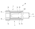
- FIG. 11 is a cross-sectional view schematically showing a modification of the galvanometer motor 1A according to the second embodiment.
- a galvanometer motor 1B of a modified example shown in FIG. 11 uses two rotors 3 used in the first and second embodiments, and rotates a rectangular stator 6 so that the direction of the magnetic flux is reversed. It is configured by sandwiching with a gap from both sides of the direction. As a result, both the front and back sides of the stator 6 can be effectively used, and a higher torque can be obtained.
- the galvano motor according to the third embodiment is different in that two galvano motors 1 according to the first embodiment are connected in the axial direction of the rotating shaft 2, and two adjacent yokes are made common to one yoke. do. Other than these, the configuration is the same as that of the first embodiment.
- FIG. 12 is a cross-sectional view schematically showing a galvanometer motor 1C according to the third embodiment.
- the galvanometer motor 1 ⁇ /b>C according to this embodiment includes two sets of units 8 each including a rotor 3 and a stator 4 in the axial direction of the rotation shaft 2 .
- the number of units 8 is not limited, and may be three or more.
- one disk-shaped yoke 53 is arranged between two sets of units 8, 8 adjacent to each other. That is, when two galvano motors 1 according to the first embodiment are connected in the axial direction of the rotating shaft 2, two adjacent yokes are made common to one yoke. Thereby, a higher torque can be obtained while suppressing an increase in size.
- the galvano-motor according to the fourth embodiment is different in that two galvano-motors 1 according to the first embodiment are connected in the axial direction of the rotating shaft 2 .
- the configuration is the same as that of the first embodiment.
- FIG. 13 is a cross-sectional view schematically showing a galvanometer motor 1D according to the fourth embodiment.
- the galvano motor 1D according to this embodiment includes two sets of units 8 each including the rotor 3 and the stator 4 in the axial direction of the rotating shaft 2 .
- the number of units 8 is not limited, and may be three or more.
- two disc-shaped yokes 52 and 51 are continuously arranged between two sets of units 8 and 8 adjacent to each other. That is, it has a structure in which two galvanometer motors 1 according to the first embodiment are connected as they are in the axial direction of the rotating shaft 2 . As a result, a higher torque can be obtained simply by connecting the galvanometer motors 1 in the axial direction.
- the rotor 3 is formed in a disc shape in the above embodiment, it is not limited to this.
- the rotor 3 may be fan-shaped. In this case, it is preferable to arrange the fan-shaped rotors 3 symmetrically with respect to the rotation axis 2 .
- the rotor 3 is composed of magnets and the stator 4 is composed of coils, but the present invention is not limited to this.
- the rotor 3 may be composed of coils, and the stator 4 may be composed of magnets.
- the rotor 3 When the rotor 3 is composed of coils, aluminum electric wires can be used as the coils. In this case, the weight of the coil can be reduced as compared with conventional general copper wire, so the inertia of the coil can be reduced. In addition, since aluminum is cheaper than copper and has a stable price, the use of aluminum for coils has a great cost advantage.
- the coils may be formed by, for example, printing (etching) a coil pattern on a printed circuit board.
- the coil can be made thinner, so the inertia of the coil can be reduced.
- the circumferential windings that do not contribute to the torque can be made thicker than the radial windings that contribute to the torque, thereby reducing the resistance. .
- a coreless coil that does not contain an iron core is used as the coil, but it is not limited to this.
- a core coil including an iron core within the coil may be used.
- the yoke 5 is provided, but the present invention is not limited to this. A configuration without the yoke 5 may be used.
- a galvano motor is applied to the swing motor of the present disclosure, but it is not limited to this.
- a swing motor for industrial machinery such as one used for a gripper of a robot hand, can be used.
- the oscillating motor of the present disclosure is a single-phase drive type, but it is not limited to this.
- the oscillating motor of the present disclosure may be of a three-phase drive type.
Landscapes
- Physics & Mathematics (AREA)
- Electromagnetism (AREA)
- Engineering & Computer Science (AREA)
- Mechanical Engineering (AREA)
- Reciprocating, Oscillating Or Vibrating Motors (AREA)
Priority Applications (2)
| Application Number | Priority Date | Filing Date | Title |
|---|---|---|---|
| PCT/JP2021/041146 WO2023084586A1 (ja) | 2021-11-09 | 2021-11-09 | 揺動モータ |
| JP2023559220A JPWO2023084586A1 (https=) | 2021-11-09 | 2021-11-09 |
Applications Claiming Priority (1)
| Application Number | Priority Date | Filing Date | Title |
|---|---|---|---|
| PCT/JP2021/041146 WO2023084586A1 (ja) | 2021-11-09 | 2021-11-09 | 揺動モータ |
Publications (1)
| Publication Number | Publication Date |
|---|---|
| WO2023084586A1 true WO2023084586A1 (ja) | 2023-05-19 |
Family
ID=86335282
Family Applications (1)
| Application Number | Title | Priority Date | Filing Date |
|---|---|---|---|
| PCT/JP2021/041146 Ceased WO2023084586A1 (ja) | 2021-11-09 | 2021-11-09 | 揺動モータ |
Country Status (2)
| Country | Link |
|---|---|
| JP (1) | JPWO2023084586A1 (https=) |
| WO (1) | WO2023084586A1 (https=) |
Citations (4)
| Publication number | Priority date | Publication date | Assignee | Title |
|---|---|---|---|---|
| JPS59177059A (ja) * | 1983-03-28 | 1984-10-06 | 高橋 義照 | 人工心臓 |
| JPH08322194A (ja) * | 1995-05-22 | 1996-12-03 | Agency Of Ind Science & Technol | アキシャル磁気浮上回転モータ及びこれを用いた回転機器 |
| JP2010246171A (ja) * | 2009-03-31 | 2010-10-28 | Hitachi Industrial Equipment Systems Co Ltd | アキシャルギャップ型回転電機 |
| JP2019187124A (ja) * | 2018-04-12 | 2019-10-24 | 株式会社デンソー | 電動モータ |
Family Cites Families (1)
| Publication number | Priority date | Publication date | Assignee | Title |
|---|---|---|---|---|
| JPS6268482U (https=) * | 1985-10-15 | 1987-04-28 |
-
2021
- 2021-11-09 JP JP2023559220A patent/JPWO2023084586A1/ja active Pending
- 2021-11-09 WO PCT/JP2021/041146 patent/WO2023084586A1/ja not_active Ceased
Patent Citations (4)
| Publication number | Priority date | Publication date | Assignee | Title |
|---|---|---|---|---|
| JPS59177059A (ja) * | 1983-03-28 | 1984-10-06 | 高橋 義照 | 人工心臓 |
| JPH08322194A (ja) * | 1995-05-22 | 1996-12-03 | Agency Of Ind Science & Technol | アキシャル磁気浮上回転モータ及びこれを用いた回転機器 |
| JP2010246171A (ja) * | 2009-03-31 | 2010-10-28 | Hitachi Industrial Equipment Systems Co Ltd | アキシャルギャップ型回転電機 |
| JP2019187124A (ja) * | 2018-04-12 | 2019-10-24 | 株式会社デンソー | 電動モータ |
Also Published As
| Publication number | Publication date |
|---|---|
| JPWO2023084586A1 (https=) | 2023-05-19 |
Similar Documents
| Publication | Publication Date | Title |
|---|---|---|
| US5804896A (en) | High speed spindle motor and apparatus equipped with high speed spindle motor | |
| JP3675772B2 (ja) | ステッピングモーター | |
| JP5117813B2 (ja) | 回転電機 | |
| EP0777314A2 (en) | Motor structure | |
| JP4727509B2 (ja) | ビームスキャナ | |
| JP2003134788A (ja) | 永久磁石式回転電機 | |
| JP4482708B2 (ja) | 永久磁石回転電機 | |
| JP2021151156A (ja) | 回転電機 | |
| WO2023084586A1 (ja) | 揺動モータ | |
| JP2002112521A (ja) | ステップモータのロータ構造 | |
| JP2002199682A (ja) | 中空モータおよび光波距離計 | |
| JPS61191248A (ja) | 歯ピツチの大きい集中巻誘導子機 | |
| WO2021149753A1 (ja) | 磁気ギアード回転電機、及びステータの製造方法 | |
| JP2003125568A (ja) | ブラシレスモータ | |
| JP2003174760A (ja) | ステッピングモーター | |
| JPH1080124A (ja) | 永久磁石式回転電機 | |
| CN115882630A (zh) | 旋转电机 | |
| JP5865663B2 (ja) | 永久磁石電気モータ | |
| JP6192788B2 (ja) | ステッピングモータ、レンズ装置、および、撮像装置 | |
| JP7627201B2 (ja) | 回転電機 | |
| JP7600065B2 (ja) | 回転電機 | |
| JPH027270B2 (https=) | ||
| JP2009050044A (ja) | アキシャルギャップモータ用ステータコア | |
| JP3045935B2 (ja) | 永久磁石型ステッピングモータ | |
| JP3594731B2 (ja) | ステッピングモータ |
Legal Events
| Date | Code | Title | Description |
|---|---|---|---|
| 121 | Ep: the epo has been informed by wipo that ep was designated in this application |
Ref document number: 21963951 Country of ref document: EP Kind code of ref document: A1 |
|
| WWE | Wipo information: entry into national phase |
Ref document number: 2023559220 Country of ref document: JP |
|
| 122 | Ep: pct application non-entry in european phase |
Ref document number: 21963951 Country of ref document: EP Kind code of ref document: A1 |