WO2023080199A1 - ろ過装置及びろ過システム - Google Patents
ろ過装置及びろ過システム Download PDFInfo
- Publication number
- WO2023080199A1 WO2023080199A1 PCT/JP2022/041153 JP2022041153W WO2023080199A1 WO 2023080199 A1 WO2023080199 A1 WO 2023080199A1 JP 2022041153 W JP2022041153 W JP 2022041153W WO 2023080199 A1 WO2023080199 A1 WO 2023080199A1
- Authority
- WO
- WIPO (PCT)
- Prior art keywords
- electrode
- anode
- discharge
- slurry
- chamber
- Prior art date
Links
- 238000001914 filtration Methods 0.000 title claims abstract description 286
- 239000002002 slurry Substances 0.000 claims abstract description 185
- 239000002245 particle Substances 0.000 claims abstract description 163
- 239000007788 liquid Substances 0.000 claims abstract description 78
- 230000005684 electric field Effects 0.000 claims abstract description 44
- 238000003860 storage Methods 0.000 claims description 53
- 238000000926 separation method Methods 0.000 claims description 19
- 238000007599 discharging Methods 0.000 claims description 18
- 230000009471 action Effects 0.000 claims description 11
- 239000000126 substance Substances 0.000 claims description 11
- 239000000284 extract Substances 0.000 claims description 8
- 239000011148 porous material Substances 0.000 claims description 7
- 238000007872 degassing Methods 0.000 claims description 3
- 230000005284 excitation Effects 0.000 claims description 3
- 230000000694 effects Effects 0.000 abstract description 4
- XLYOFNOQVPJJNP-UHFFFAOYSA-N water Substances O XLYOFNOQVPJJNP-UHFFFAOYSA-N 0.000 description 79
- 238000010586 diagram Methods 0.000 description 69
- 239000012141 concentrate Substances 0.000 description 68
- 239000007789 gas Substances 0.000 description 61
- 239000000706 filtrate Substances 0.000 description 53
- 238000005406 washing Methods 0.000 description 41
- 238000006386 neutralization reaction Methods 0.000 description 33
- 238000009429 electrical wiring Methods 0.000 description 26
- 238000000034 method Methods 0.000 description 24
- 230000003472 neutralizing effect Effects 0.000 description 15
- 239000010410 layer Substances 0.000 description 12
- 230000001105 regulatory effect Effects 0.000 description 11
- 238000011001 backwashing Methods 0.000 description 10
- 230000004048 modification Effects 0.000 description 9
- 238000012986 modification Methods 0.000 description 9
- 238000011084 recovery Methods 0.000 description 9
- 238000000638 solvent extraction Methods 0.000 description 8
- 238000004140 cleaning Methods 0.000 description 7
- 238000005536 corrosion prevention Methods 0.000 description 6
- 239000010419 fine particle Substances 0.000 description 6
- 230000008569 process Effects 0.000 description 6
- 238000004891 communication Methods 0.000 description 5
- 238000005868 electrolysis reaction Methods 0.000 description 5
- 238000000605 extraction Methods 0.000 description 5
- 238000012360 testing method Methods 0.000 description 5
- 241000894006 Bacteria Species 0.000 description 4
- 239000002028 Biomass Substances 0.000 description 4
- KDLHZDBZIXYQEI-UHFFFAOYSA-N Palladium Chemical compound [Pd] KDLHZDBZIXYQEI-UHFFFAOYSA-N 0.000 description 4
- 235000013361 beverage Nutrition 0.000 description 4
- 239000000463 material Substances 0.000 description 4
- BASFCYQUMIYNBI-UHFFFAOYSA-N platinum Chemical compound [Pt] BASFCYQUMIYNBI-UHFFFAOYSA-N 0.000 description 4
- 239000010865 sewage Substances 0.000 description 4
- 238000005549 size reduction Methods 0.000 description 4
- 238000004065 wastewater treatment Methods 0.000 description 4
- 239000011247 coating layer Substances 0.000 description 3
- 230000007423 decrease Effects 0.000 description 3
- 238000000151 deposition Methods 0.000 description 3
- 238000011043 electrofiltration Methods 0.000 description 3
- 230000001747 exhibiting effect Effects 0.000 description 3
- 229910000510 noble metal Inorganic materials 0.000 description 3
- 238000011017 operating method Methods 0.000 description 3
- 230000000149 penetrating effect Effects 0.000 description 3
- 238000011085 pressure filtration Methods 0.000 description 3
- 102000004190 Enzymes Human genes 0.000 description 2
- 108090000790 Enzymes Proteins 0.000 description 2
- 241000700605 Viruses Species 0.000 description 2
- 238000010923 batch production Methods 0.000 description 2
- 238000005260 corrosion Methods 0.000 description 2
- 230000007797 corrosion Effects 0.000 description 2
- 239000002537 cosmetic Substances 0.000 description 2
- 210000004748 cultured cell Anatomy 0.000 description 2
- 238000000855 fermentation Methods 0.000 description 2
- 230000004151 fermentation Effects 0.000 description 2
- 235000011389 fruit/vegetable juice Nutrition 0.000 description 2
- 150000004676 glycans Chemical class 0.000 description 2
- PCHJSUWPFVWCPO-UHFFFAOYSA-N gold Chemical compound [Au] PCHJSUWPFVWCPO-UHFFFAOYSA-N 0.000 description 2
- 229910052737 gold Inorganic materials 0.000 description 2
- 239000010931 gold Substances 0.000 description 2
- 230000005484 gravity Effects 0.000 description 2
- 230000020169 heat generation Effects 0.000 description 2
- 238000000338 in vitro Methods 0.000 description 2
- 150000002632 lipids Chemical class 0.000 description 2
- 230000000813 microbial effect Effects 0.000 description 2
- 244000005700 microbiome Species 0.000 description 2
- 239000000203 mixture Substances 0.000 description 2
- 229910052763 palladium Inorganic materials 0.000 description 2
- 238000005192 partition Methods 0.000 description 2
- 229910052697 platinum Inorganic materials 0.000 description 2
- 229920001282 polysaccharide Polymers 0.000 description 2
- 239000005017 polysaccharide Substances 0.000 description 2
- 102000004169 proteins and genes Human genes 0.000 description 2
- 108090000623 proteins and genes Proteins 0.000 description 2
- 230000000630 rising effect Effects 0.000 description 2
- 239000000725 suspension Substances 0.000 description 2
- FYYHWMGAXLPEAU-UHFFFAOYSA-N Magnesium Chemical compound [Mg] FYYHWMGAXLPEAU-UHFFFAOYSA-N 0.000 description 1
- VYPSYNLAJGMNEJ-UHFFFAOYSA-N Silicium dioxide Chemical compound O=[Si]=O VYPSYNLAJGMNEJ-UHFFFAOYSA-N 0.000 description 1
- GWEVSGVZZGPLCZ-UHFFFAOYSA-N Titan oxide Chemical compound O=[Ti]=O GWEVSGVZZGPLCZ-UHFFFAOYSA-N 0.000 description 1
- RTAQQCXQSZGOHL-UHFFFAOYSA-N Titanium Chemical compound [Ti] RTAQQCXQSZGOHL-UHFFFAOYSA-N 0.000 description 1
- 238000005054 agglomeration Methods 0.000 description 1
- 230000002776 aggregation Effects 0.000 description 1
- 229910052782 aluminium Inorganic materials 0.000 description 1
- XAGFODPZIPBFFR-UHFFFAOYSA-N aluminium Chemical compound [Al] XAGFODPZIPBFFR-UHFFFAOYSA-N 0.000 description 1
- PNEYBMLMFCGWSK-UHFFFAOYSA-N aluminium oxide Inorganic materials [O-2].[O-2].[O-2].[Al+3].[Al+3] PNEYBMLMFCGWSK-UHFFFAOYSA-N 0.000 description 1
- QVGXLLKOCUKJST-UHFFFAOYSA-N atomic oxygen Chemical compound [O] QVGXLLKOCUKJST-UHFFFAOYSA-N 0.000 description 1
- 230000033228 biological regulation Effects 0.000 description 1
- 230000008859 change Effects 0.000 description 1
- 239000008119 colloidal silica Substances 0.000 description 1
- 239000000470 constituent Substances 0.000 description 1
- 238000010924 continuous production Methods 0.000 description 1
- 238000001816 cooling Methods 0.000 description 1
- 230000008021 deposition Effects 0.000 description 1
- 239000012153 distilled water Substances 0.000 description 1
- 230000005611 electricity Effects 0.000 description 1
- 238000005370 electroosmosis Methods 0.000 description 1
- 238000001962 electrophoresis Methods 0.000 description 1
- 238000011156 evaluation Methods 0.000 description 1
- 239000012530 fluid Substances 0.000 description 1
- 239000001257 hydrogen Substances 0.000 description 1
- 229910052739 hydrogen Inorganic materials 0.000 description 1
- 125000004435 hydrogen atom Chemical class [H]* 0.000 description 1
- 230000006872 improvement Effects 0.000 description 1
- 238000009434 installation Methods 0.000 description 1
- 239000011810 insulating material Substances 0.000 description 1
- 229910052749 magnesium Inorganic materials 0.000 description 1
- 239000011777 magnesium Substances 0.000 description 1
- 230000014759 maintenance of location Effects 0.000 description 1
- 239000001301 oxygen Substances 0.000 description 1
- 229910052760 oxygen Inorganic materials 0.000 description 1
- 238000012545 processing Methods 0.000 description 1
- 230000004044 response Effects 0.000 description 1
- 239000007787 solid Substances 0.000 description 1
- 229910052715 tantalum Inorganic materials 0.000 description 1
- GUVRBAGPIYLISA-UHFFFAOYSA-N tantalum atom Chemical compound [Ta] GUVRBAGPIYLISA-UHFFFAOYSA-N 0.000 description 1
- 229910052719 titanium Inorganic materials 0.000 description 1
- 239000010936 titanium Substances 0.000 description 1
- OGIDPMRJRNCKJF-UHFFFAOYSA-N titanium oxide Inorganic materials [Ti]=O OGIDPMRJRNCKJF-UHFFFAOYSA-N 0.000 description 1
Images


Classifications
-
- B—PERFORMING OPERATIONS; TRANSPORTING
- B01—PHYSICAL OR CHEMICAL PROCESSES OR APPARATUS IN GENERAL
- B01D—SEPARATION
- B01D35/00—Filtering devices having features not specifically covered by groups B01D24/00 - B01D33/00, or for applications not specifically covered by groups B01D24/00 - B01D33/00; Auxiliary devices for filtration; Filter housing constructions
- B01D35/06—Filters making use of electricity or magnetism
-
- B—PERFORMING OPERATIONS; TRANSPORTING
- B03—SEPARATION OF SOLID MATERIALS USING LIQUIDS OR USING PNEUMATIC TABLES OR JIGS; MAGNETIC OR ELECTROSTATIC SEPARATION OF SOLID MATERIALS FROM SOLID MATERIALS OR FLUIDS; SEPARATION BY HIGH-VOLTAGE ELECTRIC FIELDS
- B03C—MAGNETIC OR ELECTROSTATIC SEPARATION OF SOLID MATERIALS FROM SOLID MATERIALS OR FLUIDS; SEPARATION BY HIGH-VOLTAGE ELECTRIC FIELDS
- B03C5/00—Separating dispersed particles from liquids by electrostatic effect
- B03C5/02—Separators
-
- Y—GENERAL TAGGING OF NEW TECHNOLOGICAL DEVELOPMENTS; GENERAL TAGGING OF CROSS-SECTIONAL TECHNOLOGIES SPANNING OVER SEVERAL SECTIONS OF THE IPC; TECHNICAL SUBJECTS COVERED BY FORMER USPC CROSS-REFERENCE ART COLLECTIONS [XRACs] AND DIGESTS
- Y02—TECHNOLOGIES OR APPLICATIONS FOR MITIGATION OR ADAPTATION AGAINST CLIMATE CHANGE
- Y02E—REDUCTION OF GREENHOUSE GAS [GHG] EMISSIONS, RELATED TO ENERGY GENERATION, TRANSMISSION OR DISTRIBUTION
- Y02E60/00—Enabling technologies; Technologies with a potential or indirect contribution to GHG emissions mitigation
- Y02E60/10—Energy storage using batteries
Definitions
- the present disclosure relates to filtration devices and filtration systems.
- the filtering device in the patent document below includes a filter medium provided with a plurality of holes.
- a filter medium provided with a plurality of holes.
- the supply of slurry must be stopped in order to recover the concentrate remaining on the filter medium.
- the liquid removal process is a so-called batch process, and the slurry cannot be continuously supplied to perform the liquid removal process.
- the present disclosure provides a filtration device and a filtration system that can continuously perform dewatering treatment.
- a filtration device includes a filter chamber in which slurry containing particles and liquids with different charges is supplied by a supply line, and both sides of the filter chamber are provided facing each other. , a first electrode group or a second electrode group provided with a cathode electrode or an anode electrode that separates particles and liquid in the slurry as separated substances by electric field action, and for the first electrode group and the second electrode group and a first discharge chamber and a second discharge chamber provided opposite to the filter chamber for discharging the separated matter.
- a filtration system includes a storage tank for storing slurry in which charged particles and liquid are mixed, and a sealed container provided with a plurality of cathode electrodes and a plurality of anode electrodes therein, A filtration device for continuously solid-liquid separation of the slurry inside a closed container, a supply line for continuously supplying the slurry from the storage tank to the inside of the closed container, A circulation line that extracts part of the slurry from the inside of the closed container and continuously circulates it in the storage tank; and a metering pump that adjusts the supply amount of the slurry flowing through the supply line to be less than the supply amount per unit time.
- slurry can be continuously deliquored.
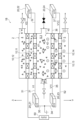
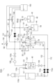
- FIG. 1 is a schematic diagram schematically showing the filtering device of Embodiment 1.
- FIG. FIG. 2 is a schematic diagram of the filtration apparatus of Embodiment 1, showing a case in which a continuous discharge operation method is performed.
- FIG. 3 is a schematic diagram of the filtration device of Embodiment 1, showing a case where a partial discharge operation method is performed.
- FIG. 4 is a schematic diagram of the filtration apparatus of Embodiment 1, showing a case where residual slurry is discharged.
- FIG. 5 is a diagram illustrating the particle concentration of the filtration device of Embodiment 1.
- FIG. FIG. 6 is a schematic diagram showing a filtering device of Modification 1.
- FIG. FIG. 7 is a schematic diagram showing a filtering device of Modification 2.
- FIG. 8 is a schematic diagram showing a filtering device of Modification 3.
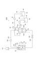
- FIG. 9 is a schematic diagram schematically showing the filtering device of Embodiment 2.
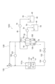
- FIG. 10 is a schematic diagram schematically showing the filtering device of Embodiment 3.
- FIG. 11 is an electrical equivalent circuit diagram of the filtering device of Embodiment 3.
- FIG. 12 is a schematic diagram schematically showing a filtering device of Embodiment 4.
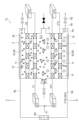
- FIG. 13 is a schematic diagram schematically showing a filtering device of Embodiment 5.
- FIG. FIG. 14 is a schematic diagram schematically showing the filtering device of Embodiment 6.
- FIG. 15A is a schematic diagram of a vibrating member installed inside the filter chamber, the first discharge chamber, and the second discharge chamber 5 of Embodiment 6.
- FIG. 15B is a schematic diagram in which vibration members are installed inside the filter chamber, the first discharge chamber, and the second discharge chamber 5 of Embodiment 6.
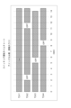
- FIG. 15C is an operation time chart of the switching box of the filtration device of Embodiment 6.
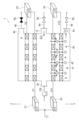
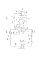
- FIG. 16 is a diagram schematically showing a filtration system of Embodiment 7.
- FIG. 17 is a schematic diagram schematically showing a filtering device of Embodiment 7.
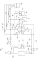
- FIG. FIG. 18 is a diagram schematically showing the filtration system of Embodiment 8.
- FIG. 19 is a schematic diagram showing how to use solid-liquid separation in the filtration system of Embodiment 8.
- FIG. 20 is a schematic diagram showing how to use backwashing in the filtration system of Embodiment 8.
- FIG. 21 is a schematic diagram showing how to use cleaning in the filtration system of Embodiment 8.
- FIG. 22 is a diagram schematically showing a filtration system of Embodiment 9.
- FIG. 23 is a diagram schematically showing the filtration system of Embodiment 10.
- FIG. FIG. 24 is a diagram schematically showing the filtration system of Embodiment 11.
- FIG. 25A is a schematic diagram of a filtration system of Embodiment 12.
- FIG. 25B is a diagram schematically showing a filtration system of a modified example of Embodiment 12.
- FIG. 26 is a diagram schematically showing a filtration system of Embodiment 13.
- FIG. 27 is a diagram schematically showing a filtration system of Embodiment 14.
- FIG. 28 is a schematic diagram schematically showing a filtering device of the filtering device of Embodiment 7.
- FIG. 29 is a schematic diagram schematically showing the filtering device of the filtering device of the thirteenth embodiment.
- 30 is a schematic diagram schematically showing a filtering device of the filtering device of Embodiment 14.
- FIG. 31A is a parallel circuit diagram showing the power supply configuration of the thirteenth or fourteenth embodiment.
- 31B is a series circuit diagram showing the power supply configuration of Embodiment 13 or 14.
- FIG. 1 is a schematic diagram schematically showing the filtering device of Embodiment 1.
- FIG. FIG. 2 is a schematic diagram of the filtration apparatus of Embodiment 1, showing a case in which a continuous discharge operation method is performed.
- FIG. 3 is a schematic diagram of the filtration device of Embodiment 1, showing a case where a partial discharge operation method is performed.
- FIG. 4 is a schematic diagram of the filtration apparatus of Embodiment 1, showing a case where residual slurry is discharged.
- FIG. 5 is a diagram illustrating the particle concentration of the filtration device of Embodiment 1.
- FIG. FIG. 6 is a schematic diagram showing a filtering device of Modification 1.
- FIG. FIG. 7 is a schematic diagram showing a filtering device of Modification 2.
- FIG. 8 is a schematic diagram showing a filtering device of Modification 3.
- the filtration device 1 is a device that separates particles 42 from slurry 40 in which particles 42 are dispersed in liquid.
- the filtration device 1 can be applied, for example, to the life science field, the sewage treatment field, the wastewater treatment field, and the like.
- life science the bio industry that cultures microbial bodies such as cultured cells, microalgae, bacteria, bacteria, and viruses, and the use of enzymes, proteins, polysaccharides, lipids, etc. produced in vitro and in the body by cultured microbial bodies
- biomedicine and cosmetics industries which are application fields, or beverage industries that handle brewing, fermentation, juice extraction, beverages, and the like.
- the filtration device 1 is a colloidal particle-based slurry in which surface-charged fine particles are highly dispersed by electrical repulsion, and can be applied to concentration and recovery of colloidal fine particles.
- the filtering device 1 includes a closed container 2, a plurality of electrodes 10 arranged inside the closed container 2, and a plurality of power sources 20 that supply predetermined potentials to the electrodes 10.
- a sealed space S is provided inside the sealed container 2 .
- the sealed container 2 includes a cylindrical side wall 2a extending in a vertical direction (hereinafter referred to as a vertical direction), an upper wall 2b closing an upper portion of the side wall 2a, a lower wall 2c closing a lower portion of the side wall 2a, have.
- a plurality of electrodes 10 are arranged inside the closed space S.
- the electrodes 10 extend in a horizontal direction perpendicular to the vertical direction, dividing the closed space S in the vertical direction.
- the sealed space S is composed of a filter chamber 3 located in the center in the vertical direction of the sealed space S, a first discharge chamber 4 located above the filter chamber 3, and a second discharge chamber 4 located below the filter chamber 3.
- the discharge chamber 5 is divided into three.
- a side wall 2a of the sealed container 2 is provided with a supply port 3a, a first discharge port 4a, and a second discharge port 5a.
- the supply port 3a, the first discharge port 4a, and the second discharge port 5a communicate the sealed space S and the external space of the sealed container 2, respectively.
- the supply port 3 a is provided on one side of the filter chamber 3 .
- One end of a supply line 102 is connected to the supply port 3a.
- the other end of the supply line 102 is connected to the storage tank 101 .
- Slurry 40 in storage tank 101 is supplied to sealed container 2 through supply line 102 .
- a supply pump 104 is provided in the supply line 102 .
- a supply pump 104 pressurizes the slurry 40 in the supply line 102 toward the filter chamber 3 .
- the closed space S is closed. Therefore, the pressurizing force of the supply pump 104 acts on the slurry 40 in the closed space S as filtering pressure.
- a valve 105 is provided in the supply line 102 .
- the first discharge port 4a is provided in the first discharge chamber 4.
- a first discharge line 4b is connected to the first discharge port 4a.
- the first discharge line 4b is provided with a first valve 4g for adjusting the flow rate.
- a pressure regulating valve (not shown) is provided downstream of the first discharge line 4b.
- the second discharge port 5a is provided in the second discharge chamber 5.
- a second discharge line 5b is connected to the second discharge port 5a.
- the second discharge line 5b is provided with a second valve 5g for adjusting the flow rate.
- a pressure regulating valve (not shown) is provided downstream of the second discharge line 5b.
- the slurry 40 is supplied to the filter chamber 3 of the closed space S. Also, the slurry 40 branches at the filter chamber 3 and flows into the first discharge chamber 4 or the second discharge chamber 5 .
- a communication port 6 is provided in the side wall 2a of the sealed container 2. As shown in FIG. The communication port 6 communicates the filter chamber 3 and the supply line 6a.
- a valve 6b is provided in the supply line 6a. This valve 6b is always closed, and is opened only when gas or liquid is supplied into the filter chamber 3 from the outside.
- the electrode 10 is provided with a plurality of holes 10a penetrating vertically.
- the slurry 40 (liquid and particles 42 ) moves vertically in the closed space S through the holes 10 a of the electrode 10 .
- An electrolytic corrosion prevention layer (not shown) is provided on the surface of the electrode 10 .
- the electrolytic corrosion prevention layer include an insulating coating layer and a conductive noble metal layer.
- Materials for the electrolytic corrosion prevention layer include, for example, titanium, aluminum, magnesium, and tantalum.
- Materials for the conductive noble metal layer include, for example, platinum, gold, and palladium.
- the thickness of the electrolytic corrosion-preventing layer, in the case of the insulating coating layer is preferably about 5 ⁇ m to 30 ⁇ m, more preferably about 5 ⁇ m to 10 ⁇ m.
- the thickness of the conductive noble metal layer such as platinum, gold, palladium, etc.
- This electrolytic corrosion prevention layer suppresses corrosion of the surface of the electrode 10 .
- the electrode 10 since the electrode 10 has an insulating coating layer, it does not come into contact with the liquid forming the slurry 40 . As a result, even if a potential is applied to the electrode 10, electrolysis is less likely to occur between the surface of the electrode 10 and the liquid.
- the multiple electrodes 10 include multiple cathode electrodes and multiple anode electrodes.
- a plurality of cathode electrodes are interposed between the filter chamber 3 and the first discharge chamber 4 .
- the plurality of cathode electrodes partition the filter chamber 3 and the first discharge chamber 4 .
- the first cathode electrode 11 and the second cathode electrode 12 are referred to in order from the one closer to the filter chamber 3 .
- a plurality of anode electrodes are interposed between the filter chamber 3 and the second discharge chamber 5 .
- the plurality of anode electrodes partition the filter chamber 3 and the second discharge chamber 5 .
- the plurality of anode electrodes they are referred to as an anode first electrode 13 and an anode second electrode 14 in order from the one closer to the filter chamber 3 .
- the first cathode electrode 11 faces the first anode electrode 13 with the filter chamber 3 interposed therebetween.
- the distance D1 between the cathode first electrode 11 and the anode first electrode 13 is a distance that allows the particles 42 in the slurry 40 to move toward the anode first electrode 13, and is, for example, 0.1 mm or more and 100 mm or less, or more. It is preferably 0.1 mm or more and 10 mm or less.
- the distance D2 between the first cathode electrode 11 and the second cathode electrode 12 is not particularly limited, but is, for example, 0.1 mm or more and 20 mm or less, more preferably 0.1 mm or more and 2 mm or less.
- the distance D3 between the anode first electrode 13 and the anode second electrode 14 is not particularly limited, but is, for example, 0.1 mm or more and 20 mm or less, more preferably 0.1 mm or more and 2 mm or less. Further, the smaller the distance D3 between the anode first electrode 13 and the anode second electrode 14, the stronger the anode electric field Ea (see FIG. 2) generated between the anode first electrode 13 and the anode second electrode .
- the hole 11a of the first cathode electrode 11 and the hole 12a of the second cathode electrode 12 allow the filter chamber 3 and the first discharge chamber 4 to communicate with each other.
- the hole diameter d1 of the hole 11a of the cathode first electrode 11 is 0.5 ⁇ m or more and 500 ⁇ m or less, for example, about 70 ⁇ m.
- the hole diameter d2 of the hole 12a of the cathode second electrode 12 is 0.5 nm or more and 1000 nm or less, for example, about 100 nm. Note that the hole diameters d1 and d2 of the holes 11a and 12a may not be the same.
- the hole 13a of the anode first electrode 13 and the hole 14a of the anode second electrode 14 allow the filter chamber 3 and the second discharge chamber 5 to communicate with each other.
- the hole diameter d3 of the hole 13a of the anode first electrode 13 and the hole diameter d4 of the hole 14a of the anode second electrode 14 are, for example, 0.1 ⁇ m or more and 5000 ⁇ m or less, more preferably 100 ⁇ m or more and 1000 ⁇ m or less. Note that the hole diameters d3 and d4 of the holes 13a and 14a may not be the same.
- the power source 20 is a device that supplies potential to the electrode 10 .
- the number of power supplies 20 is the same as the number of electrodes 10 (four in this embodiment).
- the power source 20 includes two cathode power sources (a first cathode power source 21 and a second cathode power source 22) connected to two cathode electrodes, and two anode power sources (a first power source 23 and a second power source 23) connected to two anode electrodes. 2 power supplies 24).
- the cathode first power supply 21 supplies the cathode first potential V1 to the cathode first electrode 11 .
- a first terminal 21 a of the cathode first power supply 21 is connected to the reference potential GND through an electric wiring 30 .
- the reference potential GND is, for example, a ground potential, and is not particularly limited in the present disclosure.
- a second terminal 21 b of the cathode first power supply 21 is connected to the cathode first electrode 11 by an electrical wiring 31 .
- the cathode second power supply 22 supplies the cathode second potential V2 to the cathode second electrode 12 .
- a first terminal 22 a of the cathode second power supply 22 is connected to the cathode first electrode 11 by an electrical wiring 32 .
- a second terminal 22 b of the cathode second power supply 22 is connected to the cathode second electrode 12 by an electrical wiring 33 .
- the anode first power supply 23 supplies the anode first potential V11 to the anode first electrode 13 .
- a first terminal 23 a of the anode first power supply 23 is connected to the reference potential GND by an electric wiring 34 .
- a second terminal 2102 of the anode first power supply 23 is connected to the anode first electrode 13 by an electrical wiring 35 .
- the anode second power supply 24 applies the anode second potential V12 to the anode second electrode 14 .
- a first terminal 24 a of the anode second power supply 24 is connected to the anode first electrode 13 by an electrical wiring 36 .
- a second terminal 24 b of the anode second power supply 24 is connected to the anode second electrode 14 by an electrical wiring 37 .
- cathode potential (cathode first potential V1, cathode second potential V2) and anode potential (anode first potential V11, anode second potential V12) supplied from each power supply 20 are not constant and can be changed.
- the slurry 40 is, for example, a suspension, which is a mixture of liquid and particles 42 . Particles 42 whose surfaces are charged are targeted. Moreover, the particle size of the particles 42 is not particularly limited. Particles 42 having a particle size of, for example, 1 nm or more and 5000 ⁇ m or less can also be filtered.
- the slurry 40 in this embodiment contains water as a liquid. Also, the particles 42 are negatively charged. The water molecules 41 are positively charged, and the slurry 40 as a whole is in an electrically balanced state.
- the supply pump 104 is driven to supply the slurry 40 to the filter chamber 3 .
- the supply pump 104 is continuously driven to continuously supply the slurry 40 .
- the pressure by the supply pump 104 is set so that the pressure (gauge pressure) in the closed space S is higher than the atmospheric pressure, such as 0.005 MPa or more and 0.5 MPa or less, preferably 0.02 MPa or more and 0.1 MPa or less. do.
- the pressure on the downstream side of the first discharge line 4b and the second discharge line 5b is adjusted to be substantially equal to the atmospheric pressure by a pressure regulating valve (not shown).
- pressure hereinafter referred to as filtration pressure
- filter chamber 3 filter chamber 3
- the cathode first potential V1 supplied from the cathode first power supply 21 to the cathode first electrode 11 is -20V.
- the cathode second potential V2 supplied from the cathode second power supply 22 to the cathode second electrode 12 is -30V. That is, the cathode power supply supplies cathode potentials (V1, V2) having the same polarity as the polarity (negative) of the particles 42 to the cathode electrodes. Further, the absolute value of the cathode potential supplied from the cathode power source increases as the distance from the filter chamber 3 increases (V2>V1).
- the anode first potential V11 supplied from the anode first power supply 23 to the anode first electrode 13 is set to +20V.
- the anode second potential V12 supplied from the anode second power supply 24 to the anode second electrode 14 is set to +30V.
- the anode power supply supplies anode potentials (V11, V12) with polarities different from the polarities (negative) of the particles 42 to the anode electrodes.
- the absolute value of the anode potential supplied from the anode power supply increases as the distance from the filter chamber 3 increases (V12>V11).
- particles 42 contained in slurry 40 receive repulsive force from cathode first electrode 11 charged to the same polarity (see arrow A1 in FIG. 2). ). Also, the particles 42 receive an attractive force from the anode first electrode 13 that is charged with a different polarity (see arrow B1 in FIG. 2). As a result, the particles 42 in the filter chamber 3 move toward the first anode electrode 13 . Also, the particles 42 move downward (toward the anode first electrode 13) due to gravity. As described above, many particles 42 that have flowed into the filter chamber 3 are distributed near and above the first anode electrode 13 .
- the slurry 40 (slurry 40 with a high concentration of particles 42) near and above the first anode electrode 13 passes through the holes 13a of the first anode electrode 13 and the holes 14a of the second anode electrode 14 due to the filtering pressure. and move to the second discharge chamber 5 (see arrow F1 in FIG. 2). Also, in the process of passing through the first anode electrode 13 and the second anode electrode 14 , the slurry 40 has a reduced water content and an increased content of particles 42 to form a concentrate 44 . Details will be described below.
- An anode electric field Ea is generated between the anode first electrode 13 and the anode second electrode 14 .
- This anode electric field Ea is a force that pushes back the water molecules 41 whose apparent behavior is positively charged (hereinafter also referred to as “positively charged water molecules”) from the second anode electrode 14 toward the first anode electrode 13 .
- the water molecules 41 which are apparently positively charged, receive a repulsive force from the anode electric field Ea when passing between the anode first electrode 13 and the anode second electrode 14 (see arrow A2 in FIG. 2). .
- the positively charged water molecules 41 decelerate more than the moving speed when moving to the second discharge chamber 5 simply by receiving the filtering pressure. Therefore, the amount of water passing between the anode first electrode 13 and the anode second electrode 14 per unit time is reduced. As a result, the ratio of water contained in the slurry 40 that has moved to the second discharge chamber 5 becomes smaller than that of the slurry 40 that is near and above the first anode electrode 13 .
- the anode electric field Ea between the anode first electrode 13 and the anode second electrode 14 exerts an attractive force that draws the negatively charged particles 42 from the anode first electrode 13 toward the anode second electrode 14 (Fig. 2 arrow B2). That is, the particles 42 receive an attractive force from the electric field when passing between the anode first electrode 13 and the anode second electrode 14 .
- the particles 42 are accelerated more than they would be if they moved to the second discharge chamber 5 simply under the filtering pressure.
- the amount of particles 42 passing between the anode first electrode 13 and the anode second electrode 14 per unit time increases. Therefore, the ratio of particles 42 per unit volume contained in the slurry 40 that has moved to the second discharge chamber 5 is higher than that of the slurry 40 near and above the anode first electrode 13 .
- the slurry 40 has a higher concentration of the particles 42 in the process of passing between the anode first electrode 13 and the anode second electrode 14 and becomes a concentrate 44 . Then, the concentrate 44 passes through the second discharge port 5a and is discharged from the second discharge line 5b by the filtration pressure.
- slurry 40 with a low concentration of particles 42 stays near and below the first cathode electrode 11 in the filter chamber 3 .
- This slurry 40 passes through the holes 11a of the first cathode electrode 11 and the holes 12a of the second cathode electrode 12 by the filtration pressure, and moves to the first discharge chamber 4 (see arrow F3 in FIG. 2).
- a cathode electric field Ec is generated between the cathode first electrode 11 and the cathode second electrode 12 .
- the cathode electric field Ec exerts a repulsive force that suppresses the negatively charged particles 42 from moving from the filter chamber 3 to the first discharge chamber 4 . Therefore, the particles 42 are suppressed from moving to the first discharge chamber 4 .
- An electroosmotic flow occurs in which positively charged water molecules 41 are drawn toward the first discharge chamber (see arrow F4 in FIG. 2). For this reason, the water in the filter chamber 3 accelerates more than the moving speed when it moves to the first discharge chamber 4 simply by receiving the filtering pressure. Therefore, the amount of water that moves from the filter chamber 3 to the first discharge chamber 4 per unit time increases.
- the water (filtrate 45) that has moved to the first discharge chamber 4 is discharged from the first discharge port 4a by the filtration pressure.
- the first valve 4g and the second valve 5g set the flow rate discharged from the first discharge port 4a and the second discharge port 5a to, for example, 9:1 (for example, 10-fold concentration), and a large amount of water is discharged from the first discharge port 4a. of water is discharged.
- the flow rate is set to, for example, 9:1 (eg, 10-fold concentration). can be set as appropriate.
- the filtration device 1 of the present embodiment for example, when the slurry 40 having a particle concentration of about 2% is supplied to the filter chamber 3, water (filtrate 45) having a particle concentration of about 0.02% is discharged from the first outlet 4a, and the concentrate 44 having a particle concentration of about 6% is discharged from the second outlet 5a.
- a particle removal rate of 99% or more can be exhibited.
- the above-described operating method supplies the anode electrodes (23, 24) with the force of the anode electric field Ea generated between the anode electrodes (23, 24) so that it is smaller than the filtration pressure of the closed space S.
- the anode potentials anode first potential V11, anode second potential V12
- the usage method of the filter device 1 of Embodiment 1 is not limited to this.
- intermittent discharge of the concentrate 44 may be referred to as partial discharge.
- continuous discharge of the concentrate 44 may be referred to as continuous discharge.
- the operating method by partial discharge adjusts the values of the anode first potential V11 and the anode second potential V12 shown in FIG. force greater than the filtration pressure.
- the cathode first potential V1 and the cathode second potential V2 are set to the same potentials as during the continuous discharge operation.
- the water (water molecules 41) in the filter chamber 3 passes through the holes 13a of the anode first electrode 13 due to the filtering pressure, but due to the force of the anode electric field Ea, the second discharge Movement to chamber 5 is restricted.
- Particles 42 are attracted by the attractive force of anode second electrode 14 and are in a state of being adsorbed to anode second electrode 14 . Therefore, the water and the particles 42 do not move to the second discharge chamber 5 , and the particles 42 and the water stay between the anode first electrode 13 and the anode second electrode 14 .
- the values of the anode first potential V11 and the anode second potential V12 are changed to be the same as during the continuous discharge operation.
- the particles 42 and water staying between the anode first electrode 13 and the anode second electrode 14 are moved to the second discharge chamber 5, and a concentrate 44 with a high concentration of the particles 42 is produced.
- the concentrate 44 is discharged from the second discharge port 5a by the filtering pressure.
- the values of the anode first potential V11 and the anode second potential V12 are increased again, and movement to the second discharge chamber 5 is regulated.
- the discharge of the concentrate 44 becomes intermittent.
- the concentrate 44 has a lower moisture content (greater than 6% particle concentration) than during continuous discharge.
- the valve (not shown) of the supply line 102 and the first valve 4g of the first discharge line 4b are closed.
- the second valve 5g of the second discharge line 5b and the valve 6b of the supply line 6a are opened.
- Compressed air is sent to the supply line 6 a and supplied into the filter chamber 3 from the communication port 6 . According to this, the compressed air passes from inside the filter chamber 3 through the holes 13 a of the anode first electrode 13 and the holes 14 a of the anode second electrode 14 and moves to the second discharge chamber 5 .
- the filtration device 1 of Embodiment 1 includes a sealed container 2 having a filter chamber 3, a first discharge chamber 4, and a second discharge chamber 5, and a supply line for supplying slurry 40 in which charged particles 42 and liquid are mixed. 102, a supply port 3a communicating between the supply line 102 and the filtration chamber 3, a first discharge port 4a for discharging the liquid from the first discharge chamber 4, and a concentrate 44 separated from the slurry 40 by the second discharge chamber 5. and a plurality of electrodes 10 provided with a plurality of holes 10a through which particles 42 and liquid can pass.
- the plurality of electrodes 10 has a plurality of cathode electrodes partitioning the filter chamber 3 and the first discharge chamber 4 and a plurality of anode electrodes partitioning the filter chamber 3 and the second discharge chamber 5 .
- the plurality of cathode electrodes has a cathode first electrode 11 and a cathode second electrode 12 arranged closer to the first discharge chamber 4 than the cathode first electrode 11 .
- the plurality of anode electrodes consist of an anode first electrode 13 facing the cathode first electrode 11 with the filter chamber 3 interposed therebetween, and an anode second electrode 14 disposed closer to the second discharge chamber 5 than the anode first electrode 13 .
- a cathode first potential V1 having the same polarity as the particles is supplied to the cathode first electrode 11 .
- a cathode second potential V2 having the same polarity as the particles is supplied to the cathode second electrode 12 .
- the absolute value of the cathode second potential V2 is greater than the absolute value of the cathode first potential V1.
- An anode first potential V11 having a polarity different from that of the particles is supplied to the anode first electrode 13 .
- An anode second potential V12 having a polarity different from that of the particles is supplied to the anode second electrode 14 .
- the absolute value of the second anode potential V12 is greater than the absolute value of the first anode potential V11.
- the concentrate 44 does not remain in the filter chamber 3 and is discharged from the second discharge port 5a. Therefore, the deliquoring process of the slurry 40 can be performed continuously. Also, the concentrate 44 does not accumulate in the filter chamber 3 . That is, no space is required for depositing the concentrate 44 in the filter chamber 3 . Therefore, the size reduction of the filter chamber 3 (the size reduction of the sealed container 2) can be achieved. Also, a special operation for discharging the concentrate 44 from the closed container 2 is not required.
- the first discharge chamber 4, the filter chamber 3, and the second discharge chamber 5 are arranged in this order from above in the vertical direction.
- the particles 42 move to the second discharge chamber 5 due to gravity and become difficult to move toward the first discharge chamber 4 . Therefore, the filtrate 45 recovered from the first discharge port 4a becomes clarified.
- an electrolytic corrosion prevention layer is provided on the surface of the electrode 10 of the filter device 1 of Embodiment 1.
- the anode electric field Ea generated between the anode electrodes is supplied to the plurality of anode electrodes so that the force of the anode electric field Ea generated between the anode electrodes is smaller than the filtration pressure in the sealed space S.
- the potentials (anode first potential V11, anode second potential V12) are set.
- the concentrate 44 can be discharged continuously.
- the force of the anode electric field Ea generated between the plurality of anode electrodes is made larger than the filtering pressure of the closed space S, the force of the anode electric field Ea is The third potentials (anode first potential V11, anode second potential V12) supplied to the plurality of anode electrodes are changed so as to be lower than the filtration pressure of .
- the concentrate 44 can be partially discharged.
- the present disclosure is not limited to that described in the embodiment.
- the electrode 10 of Embodiment 1 has an anti-electrolytic layer, but the present disclosure may use electrodes that do not have an anti-electrolytic layer.
- the filtration device 1 of Embodiment 1 includes a supply pump 104 that pushes out the slurry 40 inside the supply line 102 toward the filter chamber 3, but the present disclosure makes it possible to pump the slurry by a pump of a device other than the filtration device. 40 may be supplied. That is, the filtration device itself does not have to be equipped with a pump.
- the filtration pressure is applied from the supply port 3a side, but the differential pressure between the supply port 3a side and the first discharge port 4a side and the difference between the supply port 3a side and the second discharge port 5a Filtration pressure may be applied by pressure.
- the filtration device 1 of Embodiment 1 includes a plurality of cathode power sources that supply potentials to a plurality of cathode electrodes, and a plurality of anode power sources that supply potentials to a plurality of anode electrodes.
- the potential may be supplied from a power source of a device other than the filtering device. That is, the filtering device itself does not have to be equipped with a power source.
- the sealed container 2 of Embodiment 1 is arranged in the order of the first discharge chamber 4, the filter chamber 3, and the second discharge chamber 5 from the top
- the second discharge chamber 5, the filter chamber 3, and the first discharge chamber 4 may be arranged in order from the top.
- the first discharge chamber 4, the filter chamber 3 and the second discharge chamber 5 may be arranged horizontally.
- the first discharge chamber 4, the filter chamber 3 and the second discharge chamber 5 may be arranged obliquely. 7 and 8, the supply port 3a for the slurry 40 is on the bottom side.
- the positions of the supply port 3a, the first discharge port 4a, and the second discharge port 5a provided for the filter chamber 3, the first discharge chamber 4, and the second discharge chamber 5 may be appropriately set to a horizontal direction, a vertical direction, an oblique direction, or the like in the present disclosure.
- FIG. 9 is a schematic diagram schematically showing the filtering device of Embodiment 2.
- the filtering device 1A of Embodiment 2 is different from the filtering device 1 of Embodiment 1 in that it includes a filter medium 7 disposed between the first cathode electrode 11 and the second cathode electrode 12.
- the filtering device 1A of the second embodiment differs from the filtering device 1 of the first embodiment in that a dielectric 8 is arranged between the anode first electrode 13 and the anode second electrode 14 .
- the following description focuses on the differences.
- the filter medium 7 extends horizontally.
- the filter medium 7 is provided with a plurality of holes 7a penetrating in the vertical direction.
- the diameter of the hole 7a is smaller than the hole diameter d1 of the hole 11a of the first cathode electrode 11 and the hole diameter d2 of the hole 12a of the second cathode electrode 12 .
- the diameter of the holes 7a of the filter medium 7 should be approximately 4 to 20 times the diameter of the particles .
- the dielectric 8 is made of an insulating material and extends horizontally. This dielectric 8 increases the force of the anode electric field Ea acting between the first anode electrode 13 and the second anode electrode 14 .
- the dielectric 8 is provided with a hole 8a penetrating vertically.
- the diameter of the hole 8a is a size through which the particles 42 can pass, and is, for example, 1000 nm or more and 4000 nm or less.
- a filter medium such as filter paper may be used as the dielectric 8 .
- the filter medium 7 is provided between a plurality of cathode electrodes (first cathode electrode 11 and second cathode electrode 12).
- the filter medium 7 is provided between the plurality of cathode electrodes (the first cathode electrode 11 and the second cathode electrode 12). It cannot pass through 7a and cannot move to the first discharge chamber 4. A clear filtrate containing no particles 42 is thus collected in the first discharge chamber 4 .
- the force of the anode electric field Ea generated between the first cathode electrode 11 and the second cathode electrode 12 is also increased by the filter material 7 as compared with the case of the first embodiment. Therefore, the particles 42 are more difficult to move to the first discharge chamber 4 . Furthermore, the amount of water that moves to the first discharge chamber 4 per unit time increases, and the filtering processing time can be shortened.
- a dielectric 8 having a plurality of holes 8a is provided between the plurality of anode electrodes (anode first electrode 13, anode second electrode 14).
- the force of the anode electric field Ea acting between the anode first electrode 13 and the anode second electrode 14 becomes larger than in the case of the first embodiment, and the water molecules 41 moving to the second discharge chamber 5 Movement amount is reduced. That is, the moisture content of concentrate 44 is reduced. As a result, the concentration rate of concentrate 44 is increased.
- the filter device of the present disclosure may include only one of the filter medium 7 and the dielectric 8, but it is more preferable to provide the filter medium 7.
- FIG. 10 is a schematic diagram schematically showing the filtering device of Embodiment 3.
- FIG. 11 is an electrical equivalent circuit diagram of the filtering device of Embodiment 3.
- the filtering device 1B of Embodiment 3 differs from the filtering device 1 of Embodiment 1 in that it includes a bleeder resistor 50, a first electrical wiring 51, and a second electrical wiring 52.
- the bleeder resistor 50 is an electrical load.
- One end of the first electrical wiring 51 is connected to the cathode second electrode 12 .
- the other end of the first electrical wiring 51 is connected to the cathode second electrode 12 . That is, the other end of the first electric wiring 51 is connected to the cathode second electrode 12 which is the most distant from the filter chamber 3 among the plurality of cathode electrodes.
- One end of the second electric wiring 52 is connected to the bleeder resistor 50 .
- the other end of the second electrical wiring 52 is connected to the anode second electrode 14 . That is, the other end of the second electric wiring 52 is connected to the anode second electrode 14 which is the most distant from the filter chamber 3 among the plurality of anode electrodes.
- a resistance component R0 and a capacitance component C0 are connected in parallel between the cathode first electrode 11 and the anode first electrode 13.
- the resistance component R0 and the capacitance component C0 are equivalently represented by the liquid and the particles 42 entering between the first cathode electrode 11 and the first anode electrode 13 .
- a resistance component R1 and a capacitance component C1 are connected in parallel.
- the resistance component R1 and the capacitance component C1 are equivalently represented by the liquid and the particles 42 entering between the first cathode electrode 11 and the second cathode electrode 12 .
- a resistance component R2 and a capacitance component C2 are connected in parallel.
- the resistance component R2 and the capacitance component C2 are equivalently represented by the liquid and the particles 42 entering between the first anode electrode 13 and the second anode electrode 14 .
- the plurality of electrodes 10, the plurality of power sources 20, and the electrical wirings 30-37 form a closed loop circuit with the bleeder resistor 50, the first electrical wiring 51, and the second electrical wiring 52.
- the cathode second electrode 12 and the anode A current may leak from the second electrode 14 to the liquid contained in the slurry 40, leading to an increase in power consumption.
- leakage current generated from the cathode second electrode 12 and the anode second electrode 14 flows through the first electrical wiring 51 or the second electrical wiring 52 .
- the bleeder resistor 50 is arranged between the first electric wiring 51 and the second electric wiring 52 because a short circuit occurs when the first electric wiring 51 and the second electric wiring 52 are directly connected.
- the filtering device 1B of Embodiment 3 has the bleeder resistor 50 , the first electric wiring 51 having one end connected to the bleeder resistance 50 , and the second electric wiring 52 having one end connected to the bleeder resistance 50 .
- the other end of the first electric wiring 51 is connected to the electrode 10 of the plurality of cathode electrodes, which is the most distant from the filter chamber 3 .
- the other end of the second electrical wiring 52 is connected to the electrode 10 of the plurality of anode electrodes, which is the most distant from the chamber 3 .
- the filtering device 1B of Embodiment 3 since it includes the bleeder resistor 50, the first electrical wiring 51, and the second electrical wiring 52, current leakage to the liquid can be avoided and power consumption can be reduced.
- FIG. 12 is a schematic diagram schematically showing a filtering device of Embodiment 4.
- the filtration device 1C of Embodiment 4 includes two neutralization electrodes 60 (a first neutralization electrode 61 and a second neutralization electrode 62), and a neutralization power supply 63 that supplies the potential of the neutralization electrodes. It is different from the filtering device 1 of the first embodiment in this point.
- the first neutralization electrode 61 is arranged in the first discharge chamber 4 .
- the first neutralizing electrode 61 extends horizontally along the upper wall 2b of the sealed container 2.
- the first neutralizing electrode 61 faces the second electrode.
- a second neutralizing electrode 62 is arranged in the second exhaust chamber 5 .
- the second neutralizing electrode 62 extends horizontally along the bottom wall 2c of the sealed container 2.
- the second neutralizing electrode 62 faces the third electrode.
- the neutralization power supply 63 is connected to the second neutralization electrode 62 by an electrical wiring 64 and supplies a potential of a polarity different from that of the particles (positive potential) to the second neutralization electrode 62 .
- the neutralization power supply 63 is connected to the first neutralization electrode 61 by an electrical wiring 65 .
- the negatively charged particles 42 may be attracted to the second anode electrode 14 and adsorbed to the second anode electrode 14 during filtration by the filtering device 1C. Since the first anode electrode 13 has a smaller attractive force than the second anode electrode 14 , the possibility that the particles 42 are adsorbed to the first anode electrode 13 is low.
- the neutralization power supply 63 supplies the second neutralization electrode 62 with a potential V10 having a polarity different from that of the particles 42 and having a larger absolute value than the potential of the anode second electrode 14 .
- a potential of +40V is supplied to the second neutralizing electrode 62 .
- the particles 42 adsorbed to the anode second electrode 14 are attracted to the second neutralizing electrode 62 exerting a greater attractive force (see arrows H and I in FIG. 12), and the second neutralizing electrode 62 to be adsorbed.
- the potential supply to the second neutralizing electrode 62 is stopped.
- the particles 42 adsorbed to the second neutralizing electrode 62 move toward the second outlet 5a and are discharged due to the filtering pressure. Further, the neutralization power supply 63 is supplied with electrons from the first neutralization electrode 61 when supplying a potential of plus 40 V to the second neutralization electrode 62 .
- the neutralization electrode (second neutralization electrode 62) disposed in the second discharge chamber 5 of the fourth embodiment and the neutralization potential (V10) having a polarity different from that of the particles 42 are connected to the neutralization electrode (second neutralization electrode 62). and a neutralization power supply 63 that supplies the sum electrode 62).
- the absolute value of the neutralization potential (V10) is greater than the absolute value of the potential supplied to the electrode (anode second electrode 14) farthest from the filter chamber 3 among the plurality of anode electrodes (V10>V4).
- the particles 42 are easily separated from the anode second electrode 14 . Therefore, the particles 42 are less likely to remain in the closed space S, and the particles 42 can be reliably collected.
- the present disclosure may include only the second neutralization electrode 62 and the neutralization power source 63 and may not include the first neutralization electrode 61 .
- FIG. 13 is a schematic diagram schematically showing a filtering device of Embodiment 5.
- the filtration device 1D of Embodiment 5 differs from the filtration device of Embodiment 1 in that the number of cathode electrodes and anode electrodes is three.
- the filtering device 1D of the fifth embodiment differs from the filtering device of the first embodiment in that the number of power sources 20 is increased in response to the increase in the number of electrodes.
- the filtering device 1D of the fifth embodiment is different from the filtering device 1 of the first embodiment in that it includes a bleeder resistor 50 and a neutralizing electrode 60 . Differences will be described below, but since the bleeder resistor 50 and the neutralizing electrode 60 have been described in the third and fourth embodiments, description thereof will be omitted.
- the cathode electrode includes a first cathode electrode 11, a second cathode electrode 12, and a third cathode electrode 15, which are arranged in order from the filter chamber 3 side.
- the anode electrode includes an anode first electrode 13, an anode second electrode 14, and an anode third electrode 16, which are arranged in order from the filter chamber 3 side.
- the power supply 20 includes cathode power supplies (cathode first power supply 21, cathode second power supply 22, cathode third power supply 25) and anode power supplies (anode first power supply 23, anode second power supply 24, anode third power supply 26).
- the cathode first power supply 21 supplies the cathode first potential V ⁇ b>1 to the cathode first electrode 11 .
- the cathode second power supply 22 supplies the cathode second potential V2 to the cathode second electrode 12 .
- the cathode third power supply 25 supplies the cathode third potential V3 to the cathode third electrode 15 .
- the anode first power supply 23 supplies the anode first potential V ⁇ b>11 to the anode first electrode 13 .
- the anode second power supply 24 supplies the anode second potential V12 to the anode second electrode 14 .
- the anode third power supply 26 supplies the anode third potential V13 to the anode third electrode 16
- the cathode first potential V1 supplied from the cathode first power supply 21 to the cathode first electrode 11 is set to -20V.
- the cathode second potential V2 supplied from the cathode second power supply 22 to the cathode second electrode 12 is set to -30V.
- the cathode third potential V3 supplied from the cathode third power supply 25 to the cathode third electrode 15 is set to -40V.
- a cathode electric field Ec is generated between the first cathode electrode 11 and the second cathode electrode 12 and between the second cathode electrode 12 and the third cathode electrode 15 .
- These two cathodic electric fields Ec exert a repulsive force on the particles 42 . Therefore, the particles 42 are less likely to move toward the first discharge chamber 4 than in the first embodiment, and a clearer filtrate 45 than in the first embodiment can be recovered.
- the amount of water that moves from the filter chamber 3 to the first discharge chamber 4 per unit time is greater than that of the filter device 1 of the first embodiment. Therefore, relatively less water moves to the second discharge chamber 5 and the moisture content of the concentrate 44 is reduced.
- the anode first potential V11 supplied from the anode first power supply 23 to the anode first electrode 13 is set to +20V.
- the anode second potential V12 supplied from the anode second power supply 24 to the anode second electrode 14 is set to +30V.
- the anode third potential V13 supplied from the anode third power supply 26 to the anode third electrode 16 is set to +40V.
- the particles 42 are gradually attracted to the anode first electrode 13 , the anode second electrode 14 and the anode third electrode 16 and move to the second discharge chamber 5 . Further, an anode electric field Ea is generated between the anode first electrode 13 and the anode second electrode 14 and between the anode second electrode 14 and the anode third electrode 16 .
- the water (positively charged water molecules 41) moving from the filter chamber 3 to the second discharge chamber 5 receives a large repulsive force, and the movement speed to the second discharge chamber 5 increases. slow down. Therefore, less water moves to the second discharge chamber 5 per unit time, and the moisture content of the concentrate 44 decreases. Further, according to Embodiment 5, in the case of partial discharge operation, the movement of water from the filter chamber 3 to the second discharge chamber 5 is reliably suppressed.
- the number of electrodes 10 is increased, and the water content of the concentrate 44 can be reduced.
- a filter medium 7 or a dielectric 8 may be further provided between the plurality of electrodes 10 .
- three electrodes 10 are arranged between the filter chamber 3 and the first discharge chamber 4, but the number may be four or more.
- three electrodes 10 are arranged between the filter chamber 3 and the second discharge chamber 5, but the number may be four or more.
- the cathode potentials applied to the plurality of cathode electrodes and the anode potentials applied to the plurality of anode electrodes must be set so that the absolute value of the potentials increases as the distance from the filter chamber 3 increases.
- the present disclosure does not necessarily require the bleeder resistance 50 and the neutralization electrode 60 when the number of electrodes 10 is increased, and the bleeder resistance 50 and the neutralization electrode 60 are The sum electrode 60 may not be provided.
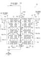
- FIG. 14 is a schematic diagram schematically showing the filtering device of Embodiment 6.
- FIG. 15A and 15B are schematic diagrams showing vibration members installed inside the filter chamber, the first discharge chamber, and the second discharge chamber 5 of Embodiment 6.
- the filter device 1E of Embodiment 6 includes vibrating members 200 (200A, 200B, 200C) inside the filter chamber 3, the first discharge chamber 4, or the second discharge chamber 5. are placed. Note that the vibrating member 200 may be provided in at least one location. In the description of the present embodiment, four anode electrodes are used.
- the vibrating member 200 may be of any type as long as it vibrates the water molecules 41 and the particles 42 that are the internal liquid.
- Examples of the vibrating member 200 include a piezoelectric vibrator, but the present invention is not limited to this.
- FIGS. 15A and 15B in electrofiltration, in the case of a slurry 40 containing particles 42 exhibiting strong agglomeration, the inside of the filter chamber 3 and the first anode electrode 13-1 and the second anode electrode 13- 2. Particles 42 stay or adhere between the third anode electrode 13-3 and the fourth anode electrode 13-4, and there is a tendency for the recovery rate of the particles 42 to decrease. These are eliminated.
- the piezoelectric member 200 it is possible to prevent the adhesion of the particles 42, so that the first anode electrode 13-1, the second anode electrode 13-2, the third anode electrode 13-3, the fourth anode The voltage applied to the electrode 13-4 can be lowered as a whole.
- Piezoelectric vibrators 200A, 200B, and 200C are installed at three locations inside the filter chamber 3, the first discharge chamber 4, and the second discharge chamber 5. It was possible to operate stably without fluctuations in the state of the filtrate and the filtration pressure.
- FIG. 15A is a schematic diagram of a vibrating member installed inside the filter chamber, the first discharge chamber, and the second discharge chamber 5.
- FIG. 15A the first anode electrode 13-1, the second anode electrode 13-2, the third anode electrode 13-3, and the fourth anode electrode 13-4 are used from the filter chamber 3 side for convenience of explanation.
- a test example in which a sequential ON/OFF switching function is added to the piezoelectric vibrator in the electric field on the side of the concentrate 45 will be described with reference to FIG. 15A.
- the first anode power supply 201-1, the second anode power supply 201-2, and the third anode power supply 201-3 on the concentration side (+) are equipped with microcomputer-controlled relays to sequentially turn on/off the switching mode. allowed to drive. By sequentially turning off the electric field, the (-) charged condensed particles staying between the (+) electrodes are released at a timing to be discharged and prevented from depositing.
- a microcomputer-controlled relay is attached to the concentration side (+) power supply (first anode power supply 201-1, second anode power supply 201-2, third anode power supply 201-3) to sequentially turn ON/OFF switching mode operation. made it possible.
- the ( ⁇ ) charged condensed particles staying between the (+) electrodes were discharged by sequentially turning off the electric field to release the particles, thereby preventing deposition of fine particles.
- Each of the first to fourth anode electrodes 13-1 to 13-4 is connected to a first anode power supply 201-1, a second anode power supply 201-2 and a third anode power supply 201-3, respectively.
- the potential of the first anode electrode 13-1 is +20V
- the potential of the second electrode 13-2 is +30V
- the potential of the third electrode 13-3 is +40V
- the potential of the fourth electrode 13-4 is +50V.
- the +30V switch box applied to the second anode electrode 13-2 When the +30V switch box applied to the second anode electrode 13-2 is turned off, the potential of the first anode electrode 13-2 becomes +20V. At this time, the relay 202-1A and the relay 202-1B are switched to each other at the same time. Normally, when the second anode electrode 13-2 is turned ON and +30V is applied to the second anode electrode 13-2, the potential difference with the third anode electrode 13-3 (+40V) is +10V. At this time, when the second anode electrode 13-2 is turned off by switching, it is electrically connected to the first anode electrode 13-1 side, and the potential of the second anode electrode 13-2 becomes +20V.
- the third anode electrode 13-3 is normally +40V, the potential difference between the third anode electrode 13-3 when the second anode electrode is OFF is +10V when the second anode electrode is always ON, and the potential difference is +40V. is doubled to +20V.
- the particles 42 are negatively charged, the effect of attracting the particles toward the third electrode 13-3 increases.
- the +40V switch box applied to the third anode electrode 13-3 is turned off, the potential of the second anode electrode 13-2 becomes +30V.
- the relay 202-2A and the relay 202-2B are switched to each other at the same time.
- the fourth anode electrode 13-4 is normally +50 V, the potential difference with the fourth anode electrode 13-4 when the third anode electrode is OFF is +10 V when the third anode electrode is always ON. The potential difference doubles to +20V.
- FIG. 15C is an operation time chart of the switching box of the filtration device of Embodiment 6.
- FIG. 15C voltage is always applied to the first anode electrode 13-1.
- the second anode electrode 13-2 to the fourth anode electrode 13-4 are repeatedly turned on for 2 seconds and turned off for 1 second. Note that this switching time can be changed as appropriate.
- FIG. 7 is a diagram schematically showing a filtration system of Embodiment 7.
- the filtration system 100 is a system that supplies the slurry 40 to the filtration device 1 , performs solid-liquid separation, and recovers a concentrate 44 and a filtrate 45 .
- the solid-liquid separation by the filtering device 1 is not a batch process but a continuous process. Therefore, in the filtration system 100, the slurry 40 can be continuously supplied, and the concentrate 44 and the filtrate 45 can be continuously collected.
- the filtration system 100 of the present embodiment can be applied, for example, to the fields of life science, sewage treatment, wastewater treatment, and the like.
- life science for example, the bio industry that cultures microorganisms such as cultured cells, microalgae, bacteria, bacteria, and viruses, and the use of enzymes, proteins, polysaccharides, lipids, etc. produced by cultured microorganisms in vitro and in the body
- biomedicine and cosmetics industries which are application fields, or beverage industries that handle brewing, fermentation, juice extraction, beverages, and the like.
- the filtration system 100 is a colloidal particle-based slurry in which surface-charged fine particles are highly dispersed by electrical repulsion, and can be applied to concentration and recovery of colloidal fine particles.
- the (+) charged particles include titanium oxide and colloidal alumina. Some particles change their charge state depending on the pH. Further, when the particles 42 dispersed in the water molecules 41 are negatively charged, the liquid water molecules 41 dispersing the particles 42 appear to be (+). behave positively. On the other hand, when the particles dispersed in the liquid water molecules 41 are positively (+) charged, the liquid water molecules 41 dispersing the particles 42 appear to behave negatively (-). .
- the filtration system 100 includes a filtration device 1, a storage tank 101, a supply line 102, a circulation line 103, a first discharge line 4b, a first discharge tank 4d, and a second discharge line. 5b and a second discharge tank 5d.
- the storage tank 101 stores the slurry 40 .
- An opening 101a is provided in the upper portion of the storage tank 101 . Therefore, the slurry 40 is supplied into the storage tank 101 through the opening 101a, and the gas contained in the slurry 40 is released into the atmosphere through the opening 101a.
- the slurry 40 is, for example, a suspension, which is a mixture of liquid and particles 42 . Particles 42 whose surfaces are charged are targeted. Moreover, the particle size of the particles 42 is not particularly limited. Particles 42 having a particle size of, for example, 1 nm or more and 5000 ⁇ m or less can also be filtered.
- the supply line 102 is a pipe that connects the closed container 2 of the filtration device 1 and the storage tank 101 .
- a supply pump 104 and a valve 105 are provided in the supply line 102 .
- a supply pump 104 sucks the slurry 40 from the storage tank 101 and delivers the slurry to the sealed container 2 .
- the supply pump 104 is a metering pump that can maintain a constant flow rate (supply amount) per unit time. Therefore, the slurry 40 flowing through the supply line 102 has its flow rate (supply amount) per unit time adjusted by the supply pump 104 to a predetermined amount.
- a valve 105 is a valve that opens and closes the supply line 102 .
- the circulation line 103 is a pipe that connects the closed container 2 and the storage tank 101 .
- a circulation pump 106 is provided in the circulation line 103 .
- the circulation pump 106 sucks the slurry 40 from the closed container 2 and sends the slurry to the storage tank 101 .
- the circulation pump 106 is a metering pump that can maintain a constant flow rate (supply amount) per unit time. Then, the flow rate (circulation amount) of the slurry 40 extracted from the closed container 2 per unit time by the circulation pump 106 is smaller than the flow rate (supply amount) of the slurry 40 supplied to the closed container 2 per unit time. adjusted to be
- the first discharge line 4b is a pipe for discharging the filtrate 45 from the sealed container 2.
- a metering pump 4c for adjusting the flow rate of the filtrate 45 is provided in the first discharge line 4b.
- the filtrate 45 discharged through the first discharge line 4b is stored in the first discharge tank 4d.
- An opening 4e is provided in the upper portion of the first discharge tank 4d.
- the second discharge line 5b is a pipe for discharging the concentrate 44 from the closed container 2.
- a metering pump 5c for adjusting the flow rate of the concentrate 44 is provided in the second discharge line 5b.
- the concentrate 44 discharged from the second discharge line 5b is stored in the second discharge tank 5d.
- An opening 5e is provided in the upper portion of the second discharge tank 5d.
- FIG. 17 is a schematic diagram schematically showing the filtering device of Embodiment 7.
- the filtering device 1F includes a closed container 2, a plurality of electrodes 10 arranged inside the closed container 2, and a plurality of power sources 20 that supply predetermined potentials to the electrodes 10.
- the inside of the sealed container 2 is a sealed space S.
- the sealed container 2 has a cylindrical side wall 2a extending in the vertical direction (vertical direction), an upper wall 2b closing the upper portion of the side wall 2a, and a lower wall 2c closing the lower portion of the side wall 2a.
- a plurality of electrodes 10 are arranged in the closed space S.
- the electrode 10 extends in the vertical direction (vertical direction).
- the plurality of electrodes 10 are parallel to each other.
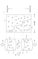
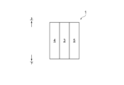
- the electrodes 10 are arranged so as to divide the sealed space S in a direction (horizontal direction) orthogonal to the vertical direction. Therefore, the sealed space S consists of the filter chamber 3 located in the central part of the filter device 1F, the first discharge chamber 4 located on the left side of the filter chamber 3, and the second discharge chamber 5 located on the right side of the filter chamber 3. , are divided into three.
- the sealed container 2 is provided with a supply port 3a, a first discharge port 4a, a second discharge port 5a, and an extraction port 116.
- the supply port 3a, the first discharge port 4a, the second discharge port 5a, and the extraction port 116 communicate the sealed space S with the external space of the sealed container 2, respectively.
- the supply port 3a is provided in the filter chamber 3. Also, the supply port 3 a is provided in the lower wall 2 c and connected to the supply line 102 . Thereby, the slurry 40 is supplied to the filter chamber 3 from the supply line 102 . Also, the supply pump 104 pressurizes the slurry 40 in the supply line 102 toward the filter chamber 3 . Also, the closed space S is closed. Therefore, the pressurizing force of the supply pump 104 acts on the slurry 40 in the closed space S as filtering pressure.
- the first discharge port 4a is provided in the first discharge chamber 4. Also, the first discharge port 4a is provided in the upper portion of the side wall 2a and is connected to the first discharge line 4b. A second discharge port 5 a is provided in the second discharge chamber 5 . The first discharge port 4a is provided in the upper part of the side wall 2a and connected to the second discharge line 5b. The outlet 116 is provided in the filter chamber 3 . The outlet 116 is provided on the upper wall 2 b and connected to the circulation line 103 .
- the slurry 40 is separated into the filtrate 45 and the concentrate 44 in the closed space S.
- Filtrate 45 flows into first discharge chamber 4 and concentrate 44 flows into second discharge chamber 5 .
- the voltage is applied to the electrode 10 during solid-liquid separation. Therefore, the electrode 10 generates heat and the slurry 40 is heated.
- gas 47 is generated around the electrode 10 due to electrolysis of water. The gas 47 moves to the upper part of the closed space S due to buoyancy.
- the supply pump 104, the circulation pump 106, the metering pump 4c, and the metering pump 5c are driven.
- the slurry 40 is supplied from the storage tank 101 to the filter chamber 3 .
- the slurry 40 in the upper part of the filter chamber 3 is discharged and flows into the storage tank 101 .
- the filtrate 45 in the upper part of the first discharge chamber 4 (near the first discharge port 4a) flows into the first discharge tank 4d.
- the concentrate 44 on the upper side (near the second outlet 5a) of the second discharge chamber 5 flows into the second discharge tank 5d.
- the gas 47 accumulated in the upper part of the filter chamber 3 in the closed space S is accompanied by the slurry 40 flowing in the circulation line 103 and discharged from the filter chamber 3 . Therefore, the slurry 40a containing the gas 47 moves toward the storage tank 101 through the circulation line 103, and the gas 47 is diffused on the upper open side of the slurry 40 stored in the storage tank 101.
- FIG. The gas 47 entrained in the slurry 40a containing the gas 47 passes through the opening 101a of the storage tank 101 and is released into the atmosphere. Also, the slurry 40 gradually moves downward in the storage tank 101 after releasing the gas 47 . Then, it returns to the sealed container 2 through the supply line 102 .
- the cause of gas generation is that when electricity is applied to water, the water is electrolyzed, resulting in the generation of hydrogen (H 2 ) and oxygen (O 2 ).
- the slurry 40a containing the gas 47 extracted by the circulation line 103 is cooled by releasing heat (to normal temperature) when passing through the circulation line 103 or being stored in the storage tank 101. Therefore, the temperature of the extracted slurry 40 is suppressed from rising.
- the slurry 40 remaining in the closed space S without being extracted by the circulation line 103 is cooled by the new slurry 40 supplied from the supply line 102 .
- the slurry 40 in the closed space S is extracted by the circulation line 103 .
- the amount of new slurry 40 supplied is increased compared to the case where the circulation line 103 is not used. Therefore, the slurry 40 staying in the closed space S is cooled by a large amount of new slurry 40, and the temperature is suppressed from rising.
- the gas 47 accumulated in the upper part of the first discharge chamber 4 is discharged from the first discharge chamber 43 together with the filtrate 45 flowing through the first discharge line 4b. Then, the filtrate 45a containing the gas 47 moves to the first discharge tank 4d, and the gas 47 is released into the atmosphere from the opening 4e of the first discharge tank 4d.
- the gas accumulated in the upper part of the second discharge chamber 5 is accompanied by the concentrate 44 flowing through the second discharge line 5b and discharged from the second discharge chamber 5. Then, the concentrate 44a containing the gas 47 moves to the second discharge tank 5d, and the gas 47 is released into the atmosphere from the opening 5e of the second discharge tank 5d.
- the slurry 40 can be continuously supplied from the storage tank 101 to the filter chamber 3 for deliquoring, and the temperature rise of the slurry 40 can be suppressed. Also, the gas 47 in the sealed container 2 is removed.
- the filtration device 1F of Embodiment 7 is obtained by arranging the filtration device 1 of Embodiment 1 shown in FIG. 1 vertically (this is a modification of FIG. 7 described above).
- the supply port 3a of the supply line 103 of the filter device 1F of the filtration system 100 of Embodiment 7 is connected to the vicinity of the bottom side of the filter chamber 3 of the closed container 2, and the slurry 40 is supplied to the closed container.
- the circulation line 103 extracts the slurry 40a containing the unfiltered gas 47 that has passed through the filter chamber 3 from the vicinity of the upper portion of the filter chamber 3 of the closed vessel 3. Since other configurations are the same as those of the filtering device 1 of Embodiment 1, description thereof will be omitted.
- the filtration device when placed horizontally, it is connected to one side (left side) side of the filter chamber 3 of the closed container 2, and the slurry 40 is supplied into the closed container, and the circulation line (103) is Alternatively, the slurry (40) may be extracted from the side (right side) opposite to one side of the filter chamber 3 of the closed vessel (3).
- the filtration system 100 of Embodiment 7 includes a storage tank 101 for storing slurry 40 in which charged particles 42 and liquid are mixed, and a plurality of cathode electrodes 11 and 12 inside. (10) and a plurality of anode electrodes 13, 14 (10) are provided in the closed container 2, the filtering device 1 continuously performs solid-liquid separation of the slurry 40 inside the closed container 2, and the storage tank 101.
- a supply line 102 that continuously supplies the slurry 40 from the inside of the closed container 2, a circulation line 103 that extracts part of the slurry 40 from the inside of the closed container 2 and continuously circulates it in the storage tank 101, and a circulation line 103, and a metering pump (circulation pump 106) that adjusts the circulation amount per unit time of the slurry 40 flowing through the circulation line 103 to be less than the supply amount per unit time of the slurry 40 flowing through the supply line 102; Prepare.
- a portion of the slurry 40 is extracted from the closed container 2 by the circulation line 103 .
- the gas 47 is discharged to the outside of the sealed container 2 together with the extracted slurry 40 .
- the liquid removal treatment can be performed continuously.
- the gas 47 is removed from the inside of the sealed container 2 .
- the slurry 40 extracted by the circulation line 103 circulates in the storage tank 101 to release heat.
- a large amount of slurry 40 is supplied to the slurry 40 remaining inside the closed container 2 to cool it. Therefore, the temperature rise of the slurry 40 is suppressed.
- the filter device 1F of Embodiment 7 includes a sealed container 2 having a filter chamber 3, a first discharge chamber 4, and a second discharge chamber 5, a supply line 102 and the filter chamber 3. a first discharge port 4a for discharging the liquid from the first discharge chamber 4; and a second discharge port 5a for discharging the concentrate 44 in which the liquid is separated from the slurry 40 from the second discharge chamber 5. , a plurality of electrodes 10 provided with a plurality of holes 10a through which particles 42 and liquid can pass. The plurality of electrodes 10 has a plurality of cathode electrodes partitioning the filter chamber 3 and the first discharge chamber 4 and a plurality of anode electrodes partitioning the filter chamber 3 and the second discharge chamber 5 .
- the plurality of cathode electrodes has a cathode first electrode 11 and a cathode second electrode 12 arranged closer to the first discharge chamber 4 than the cathode first electrode 11 .
- the plurality of anode electrodes consist of an anode first electrode 13 facing the cathode first electrode 11 with the filter chamber 3 interposed therebetween, and an anode second electrode 14 arranged closer to the second discharge chamber 5 than the anode first electrode 13 .
- a cathode first potential V1 having the same polarity as the particles is supplied to the cathode first electrode 11 .
- a cathode second potential V2 having the same polarity as the particles is supplied to the cathode second electrode 12 .
- the absolute value of the cathode second potential V2 is greater than the absolute value of the cathode first potential V1.
- An anode first potential V11 having a polarity different from that of the particles is supplied to the anode first electrode 13 .
- An anode second potential V12 having a polarity different from that of the particles is supplied to the anode second electrode 14 .
- the absolute value of the second anode potential V12 is greater than the absolute value of the first anode potential V11.
- the concentrate 44 is discharged from the second discharge port 5a. Therefore, the deliquoring process of the slurry 40 can be performed continuously. Also, the concentrate 44 does not stay in the filter chamber 3 . In other words, a space for retaining the concentrate 44 in the filter chamber 3 becomes unnecessary. Therefore, the size reduction of the filter chamber 3 (the size reduction of the sealed container 2) can be achieved.
- the circulation line 103 of Embodiment 7 extracts the slurry 40 from the upper portion of the closed container 2 .
- the filter chamber 3, the first discharge chamber 4 and the second discharge chamber 5 are arranged horizontally.
- the sealed container 2 has an extraction port 116 that communicates the upper portion of the filter chamber 3 and the circulation line 103 .
- the first discharge port 4 a discharges the liquid (filtrate 45 ) from the upper portion of the first discharge chamber 4 .
- the second discharge port 5 a discharges the liquid from the upper part of the second discharge chamber 5 .
- the gas 47 accumulates in the inner upper part of the sealed container 2 (the filter chamber 3, the first discharge chamber 4, and the second discharge chamber 5). Therefore, according to the above configuration, by entraining a large amount of gas 47 with the slurry 40, the concentrate 44, and the filtrate 45 from the outlet 116, the first outlet 4a, and the second outlet 5a, Gas 47 can be withdrawn.
- the filtration device has a filter chamber in which a slurry 40 containing particles (+) 42 and liquid (water molecules ( ⁇ ) 41) having different charges is supplied through a supply line 102. 3, and cathode electrodes 11, 12 provided on both sides of the filter chamber 3 facing each other and separating particles 42 and liquid (water molecules 41) in the slurry 40 as separated substances by electric field action.
- a first electrode group 10A or a second electrode group 10B having anode electrodes 13 and 14, and the first electrode group 10A and the second electrode group 10B are provided opposite to the filter chamber 3 to discharge separated substances.
- a first discharge chamber 4 and a second discharge chamber 5 are provided.
- the separated matter is the filtrate 45 separated from the slurry 40 in the filter chamber 3 in the first discharge chamber 4, and separated from the slurry 40 in the filter chamber 3 in the second discharge chamber 5. Concentrate 44.
- the slurry 40 can be continuously deliquored, and the gas 47 generated in the filter chamber 3 by electrolysis is removed and generated in the closed container S. It is possible to prevent the gas from accumulating.
- FIG. 18 is a diagram schematically showing the filtration system of Embodiment 8.
- the eighth embodiment differs from the seventh embodiment in that a filtration system 100A is provided instead of the filtration system 100.
- the filtration system 100A of Embodiment 8 differs from Embodiment 7 in that it includes a compressor 110, a washing water tank 111, a washing drainage line 120, and gas vent valves (122, 132, 142).
- the filtration system 100A of the eighth embodiment differs from the filtration system 100 of the seventh embodiment in that the feed pump 104 is not provided. The following description focuses on the differences.
- the sealed container 2 of the filtration system 100A is provided with a first backwashing port 4f and a second backwashing port 5f.
- the first backwash port 4 f communicates the external space of the sealed container 2 with the first discharge chamber 4 .
- the second backwash port 5f communicates the external space of the sealed container 2 and the second discharge chamber 5. As shown in FIG.
- the first backwashing port 4f and the second backwashing port 5f are located in the center of the closed container 2 in the vertical direction.
- Compressor 110 is a device that discharges compressed air. Compressed air discharged from the compressor 110 is sent to the storage tank 101 through the first line 110a, or sent to the washing water tank 111 through the second line 110b.
- the reservoir 101 is a sealed container with a closed top.
- the first discharge tank 4d and the second discharge tank 5d are also closed containers.
- the slurry 40 in the storage tank 101 is pressurized and flows into the supply line 102 . As a result, the slurry 40 moves to the closed container 2 (filter chamber 3).
- a pressurizing means such as a gas cylinder may be used.
- the washing water tank 111 stores washing water for washing the filtering device 1 .
- washing water examples include ion-exchanged water, distilled water, pure water, and clarified filtrate (co-liquid), but are not particularly limited in the present disclosure.
- the outflow port of the washing water tank 111 is connected to the reverse washing line 112 and the washing line 113 .
- the backwashing line 112 branches in the middle, one branched end is connected to the first backwashing port 4f, and the other branched end is connected to the second backwashing port 5f.
- Wash line 113 is connected to supply line 102 .
- the washing water tank 111 is a closed container with a closed top.
- the washing water is pressurized and flows into the reverse washing line 112 or the washing line 113 .
- the reverse washing line 112 is provided with a valve 112 a for opening and closing the flow path of the reverse washing line 112 .
- the washing line 113 is provided with a valve 113 a for opening and closing the flow path of the washing line 113 .
- the washing drain line 120 has one end connected to the circulation line 103 (more specifically, between the outlet 116 and the valve 103a) and the other end connected to the filtrate tank 150 .
- the cleaning drainage line 120 is provided with a valve 120 a for opening and closing the cleaning drainage line 120 .
- the first gas vent valve 122 is a valve that extracts the gas 47 flowing through the circulation line 103 and releases it into the atmosphere.
- the pipe 121 of the first gas vent valve 122 of this embodiment is connected to the confluence of the circulation line 103 and the cleaning drainage line 120 . Also, the slurry 40 that has flowed toward the first gas vent valve 122 along with the gas 47 is discharged to the filtrate tank 150 .
- the second gas vent valve 132 is a valve that extracts the gas 47 flowing through the first discharge line 4b and releases it into the atmosphere. Also, the filtrate 45 that has flowed through the pipe 131 of the second gas vent valve 132 along with the gas 47 is discharged to the filtrate tank 150 .
- the third gas release valve 142 is a valve that extracts the gas 47 flowing through the second discharge line 5b and releases it during endurance. Also, the concentrate 44 that has flowed through the pipe 141 of the third gas vent valve 142 along with the gas 47 is discharged to the filtrate tank 150 .
- the filtrate tank 150 is a tank for collecting the fluid flowing through the washing drain line 120 and the pipes 121 , 131 and 141 . Next, a method of using the filtration system 100A of Embodiment 8 will be described.
- FIG. 19 is a schematic diagram showing how to use solid-liquid separation in the filtration system of Embodiment 8.
- FIG. 19 when the slurry 40 is solid-liquid separated by the filtration device 1, the valves 105, 103a, 133, and 143 are opened. Meanwhile, the valves 112a, 113a and 120a are closed. Compressor 110 is driven to supply compressed air to storage tank 101 (see arrow A1). As a result, the slurry 40 in the storage tank 101 passes through the supply line 102 and moves to the filter chamber 3 of the closed container 2 (see arrow A2).
- the solid-liquid separation by the filtering device 1 causes the filtrate 45 to move to the first discharge chamber 4 .
- Concentrate 44 moves to second discharge chamber 5 .
- the slurry 40 located in the upper part of the filter chamber 3 moves from the outlet 116 to the circulation line 103 (see arrow A3).
- the gas 47 staying in the upper part of the filter chamber 3 flows into the circulation line 103 together with the slurry 40 .
- the gas 47 moving through the circulation line 103 is discharged into the atmosphere through the first gas vent valve 122 (see arrow A4). Slurry 40 that has flowed toward first vent valve 122 is collected in filtrate tank 150 . Also, the slurry 40 moving through the circulation line 103 is circulated to the storage tank 101 (see arrow A5). Then, the slurry 40 is deposited on the upper portion of the slurry 40 stored in the storage tank 101 . The slurry 40 radiates the heat absorbed in the closed container 2 and is cooled. After cooling, it moves through the supply line 102 again and is supplied to the filter chamber 3 . Then, the slurry 40 in the filter chamber 3 is cooled by the supplied new slurry 40 .
- the filtrate 45 that has moved to the first discharge chamber 4 is discharged from the first discharge port 4a and flows through the first discharge line 4b (see arrow B1). Also, the gas 47 in the upper part of the first discharge chamber 4 is entrained with the filtrate 45 and flows to the first discharge line 4b. Then, the gas 47 is released into the atmosphere from the second gas vent valve 132 (see arrow B2). Also, the filtrate 45 that has flowed toward the second gas vent valve 132 is recovered in the filtrate tank 150 . The filtrate 45 flowing through the first discharge line 4b is collected in the first discharge tank 4d (see arrow B3).
- the concentrate 44 moved to the second discharge chamber 5 is discharged from the second discharge port 5a and flows through the second discharge line 5b (see arrow C1). Also, the gas 47 at the top of the second discharge chamber 5, entrained with the concentrate 44, flows to the second discharge line 5b. The gas 47 is then released into the atmosphere from the third gas vent valve 142 (see arrow C2). Concentrate 44 that flows toward third vent valve 142 is collected in filtrate tank 150 . Then, the concentrate 44 flowing through the second discharge line 5b is collected in the second discharge tank 5d (see arrow C3).
- the gas 47 is released from the gas vent valves (122, 132, 142). Also, temperature rise of the slurry 40 is avoided.
- FIG. 20 is a schematic diagram showing how to use backwashing in the filtration system of Embodiment 8.
- FIG. 20 when backwashing the filter device 1A, the valves 113a, 105, 133, 143, and 103a are closed. Open the valves 112a, 120a.
- Compressor 110 is driven to supply compressed air to washing water tank 111 (see arrow E1). Washing water in the washing water tank 111 flows through the reverse washing line 112, passes through the first reverse washing port 4f, and flows into the first discharge chamber 4 (see arrow E2). Also, the wash water passes through the second backwash port 5f and flows into the second discharge chamber 5 (see arrow E3).
- the washing water in the first discharge chamber 4 and the second discharge chamber 5 flows through the opening of the electrode 10 into the filter chamber 3 .
- the slurry 40 adhering to the electrode 10 is washed away.
- the washing water that has flowed into the filter chamber 3 passes through the outlet 116 and flows into the circulation line 103 (see arrow E4).
- the washing water passes through the washing drainage line 120 and is collected in the filtrate tank 150 (see arrow E5).
- FIG. 21 is a schematic diagram showing how to use cleaning in the filtration system of Embodiment 8.
- FIG. Next, a method of using cleaning by the filtration system 100A will be described.
- the valves 112a, 105, 133, 143 and 103a are closed. Open the valves 113a, 120a.
- Compressor 110 is driven to supply compressed air to washing water tank 111 (see arrow F1).
- the washing water in the washing water tank 111 flows through the washing line 113, passes through the supply port 3a, and flows into the filter chamber 3 (see arrow F2).
- the wash water flows from the filter chamber 3 to the first discharge chamber 4 and the second discharge chamber 5, and is discharged from the outlet 116 (see arrow F3).
- the washing water passes through the washing drainage line 120 and is collected in the filtrate tank 150 (see arrow F4).
- the valve 113a may be opened to supply washing water from the supply port 3a.
- FIG. 22 is a schematic diagram of a ninth embodiment filtration system.
- a filtration system 100B of the ninth embodiment differs from the seventh embodiment in that the supply pump 104 is not provided.
- the filtration system 100B of Embodiment 9 is different from Embodiment 7 in that the storage tank 101 is sealed.
- the filtration system 100B of the ninth embodiment differs from the seventh embodiment in that the storage tank 101 is provided with a pressure regulating valve 101b.
- the filtration system 100B of Embodiment 9 is different from Embodiment 7 in that an air compressor 110 is provided.
- a method of using the filtration system 100B of Embodiment 9 will be described.
- the compressor 110 When the compressor 110 is driven, compressed air is supplied to the storage tank 101 (see arrow G1). Further, the gas 47 accumulated in the upper part of the inner chamber 3 of the closed space S accompanies the slurry 40, passes through the circulation line 103, and is diffused within the storage tank 101 (see arrow G2). Therefore, the pressure in the storage tank 101 rises above the atmospheric pressure. Therefore, the amount of compressed air supplied from the compressor 110 can be set smaller than in the case of the eighth embodiment. Specifically, the pressure supplied by the compressor 110 is such that the internal pressure of the storage tank 101 is 0.02 MPa to 0.2 MPa, which is a slight pressure.
- the gas 47 accumulated in the upper part of the filter chamber 3 is continuously supplied into the storage tank 101 . Therefore, the internal pressure of the storage tank 101 gradually increases. Then, when the internal pressure of the storage tank 101 exceeds a predetermined value, the pressure regulating valve 101b is activated. Therefore, the gas 47 in the storage tank 101 is discharged outside the storage tank 101 (see arrow G3). Thereby, it is possible to avoid the storage tank 101 from being damaged. Moreover, the control for adjusting the amount of compressed air supplied from the compressor 110 can be eliminated.
- the gas accumulated in the upper part of the first discharge chamber 4 accompanies the filtrate 45 flowing through the first discharge line 4b, moves to the first discharge tank 4d, and moves to the first discharge. It is discharged into the atmosphere from the opening 4e of the tank 4d.
- the gas accumulated in the upper part of the second discharge chamber 5 accompanies the concentrate 44 flowing through the second discharge line 5b, moves to the second discharge tank 5d, and is released into the atmosphere from the opening 5e of the second discharge tank 5d.
- the compressor 110 is used to supply a slight pressurization to the storage tank 101, but the present disclosure is not limited to this.
- the storage tank 101 may be arranged above the filtration device 1 and the slurry 40 in the storage tank 101 may be supplied to the filtration device 1 by hydraulic head pressure.
- the present disclosure may be a filtration device using electrodes, and may be a filtration device other than the filtration devices shown in each embodiment.
- the electrodes 10 in the embodiment extend vertically, they may be arranged so as to be inclined in the vertical direction.
- the outlet 116 is provided in the upper wall 2b, but may be provided in the upper part of the side wall 2a.
- the first discharge port 4a and the second discharge port 5a may be provided on the upper wall 2b instead of the upper portion of the side wall 2a. This is because even in such a modified example, the gas 47 in the sealed container 2 can be discharged from the outlet 116, the first outlet 4a, and the second outlet 5a.
- FIG. 23 is a diagram schematically showing the filtration system of Embodiment 10.
- FIG. In the filtration system 100C of Embodiment 10, as shown in FIG. 23, in order to keep the pressurized state of the filter chamber 3 constant, A pressure regulating line 128 is installed, and a back pressure valve (pressure regulating valve) 129 is installed in the pressure regulating line 128 .
- the back pressure valve 129 has a function of setting it to, for example, 0.05 MPa, and releasing the pressure when the pressure exceeds 0.05 MPa. This maintains constant pressure filtration.
- the metering pump 104 supplies the slurry 40 supplied through the line 102 at a flow rate of, for example, "3". At this time, it is ideal to balance by setting the discharge amount of the filtrate 45 to "1", the discharge amount of the concentrate 44 to "1", and the flow rate of circulation to "1", for example. However, actual operating conditions cannot maintain this ideal balance due to various factors.
- the back pressure valve 129 is installed in the pressure adjustment line 128 in order to keep the pressurized state constant so that the flow rate of the slurry 40 from the circulation line 103 is "1". Operation of the pressure valve 129 allows constant pressure filtration to be maintained. As a result, the separated substances (filtrate 45 and concentrate 44) can be stably separated from the slurry 40 continuously. Installation of the pressure regulation line 128 and the back pressure valve 129 is preferable because it can be applied to other embodiments of the present invention to reliably maintain constant pressure filtration.
- FIG. 24 is a diagram schematically showing the filtration system of Embodiment 11.
- the filtration system 100D of the eleventh embodiment includes a vibrating member 200 in at least one place inside the filter chamber 3, the first discharge chamber 4, or the second discharge chamber 5, as shown in FIG.
- the filtration system 100D of Embodiment 11 separates the slurry 40 containing particles 42 exhibiting strong cohesiveness, the inside of the filter chamber 3 and the first anode electrode 13-1, the second anode electrode 13-2, The retention and adhesion of particles 42 occur between the third anode electrode 13-3 and the fourth anode electrode 13-4, and there is a tendency for the recovery rate of the particles 42 to decrease. be canceled. Since the details are described in the sixth embodiment, the description thereof is omitted.
- FIG. 25A is a schematic diagram of a filtration system of Embodiment 12.
- FIG. The filtration system 100E-1 of the twelfth embodiment, as shown in FIG. and a first separation electrode group 10A and a first separation electrode group 10A which are provided opposite to both side surfaces of the filter chamber 3 to which is supplied and electrically separates the particles 42 in the slurry 40 from the medium (water molecules 41).
- Two separated electrode groups 10B, and a cathode-side first separator which is provided on the side opposite to the filter chamber of the first separated electrode group 10A and the second separated electrode group 10B and discharges separated substances (medium (water molecules 41), particles 42).
- the filter unit provided with the discharge chamber 4 and the second discharge chamber 5 on the anode side is regarded as one unit module, and when the module composed of the filter units 160 (160-1, 160-2, . . . ) is connected, the connection A plurality of chambers 161 are used to connect them.
- the filter device group is constructed by sequentially folding back the connection of the filter device units 160 (160-1, 160-2, . Filtration area expansion) can be achieved, and the discharge amount of separated substances (filtrate 45, concentrate 44) can be increased.
- FIG. 25B is a diagram schematically showing a filtration system of a modified example of Embodiment 12.
- FIG. A filtration system 100E-2 of a modification of the twelfth embodiment does not use the connection chamber 161 for connection used in FIG. 25A, and either the first discharge chamber 4 or the second discharge chamber 5 is shared. In this embodiment, the second discharge chamber 5 is shared.
- a filter unit 160-3 (not shown) may be provided next to the filter unit 160-2 so that the first discharge chamber 4 is shared.
- either the first discharge chamber 4 or the second discharge chamber 5 is used without using the connection chamber 161 used in the filtration system 100E-1. are shared. As a result, even if the throughput of the filtering device is increased, the capacity of the filtering device as a whole can be reduced. In addition, since the connection chamber 161 and either the first discharge chamber 4 or the second discharge chamber 5 can be eliminated, the number of parts of the filtering device can be reduced.
- FIG. 13 26 is a diagram schematically showing a filtration system of Embodiment 13.
- FIG. 28 is a schematic diagram schematically showing the filtering device of the filtering device of Embodiment 7, which is the same as FIG.
- FIG. 29 is a schematic diagram schematically showing the filtering device of the filtering device of the thirteenth embodiment.
- 31A and 31B are circuit diagrams showing the power supply configurations of the thirteenth and fourteenth embodiments, FIG. 31A being a parallel circuit diagram and FIG. 31B being a series circuit diagram. As shown in FIG.
- a slurry 40 containing particles (+) 42 and liquids (water molecules ( ⁇ ) 41) with different charges is fed into a supply line (tube ) 102 and at least two or more filter chambers 3 provided facing each other on both sides of the filter chamber 3 and separating the particles 42 and the liquid (water molecules 41) in the slurry 40 by the action of an electric field.
- a first electrode group 10A and a second electrode group 10B provided with either one or both of a cathode electrode and an anode electrode, and a concentrate 44 and a filtrate 45 which are separated substances provided on the opposite side of the electrode group from the filter chamber 3
- the filtration device 1G includes a first discharge chamber 4 and a second discharge chamber 5 for discharging the . Then, the first electrode group 10A and the second electrode group 10B are on the same polarity cathode side, and the electrodes constituting the electrode group have pores, and the polarity (-) of the electrode groups 10A and 10B is different from the polarity (+ ) is disposed in the filter chamber 3 on the anode side.
- the filtering device 1G of the thirteenth embodiment has the first discharge chambers 4, 4, which are ports for discharging the filtrate 45, on the left and right sides, the filtering device 1F of the seventh embodiment shown in FIG.
- the recovery amount of the filtrate 45 can be doubled compared to the case of
- FIG. 27 is a diagram schematically showing a filtration system of Embodiment 14.
- FIG. 30 is a schematic diagram schematically showing a filtering device of the filtering device of Embodiment 14.
- FIG. 27 in the filtration system 100F of the fourteenth embodiment, a slurry 40 containing particles (+) 42 and liquids (water molecules ( ⁇ ) 41) with different charges is fed into a supply line (tube ) 102 and at least two or more filter chambers 3 provided facing each other on both sides of the filter chamber 3 and separating the particles 42 and the liquid (water molecules 41) in the slurry 40 by the action of an electric field.
- a first electrode group 10A and a second electrode group 10B having either one or both of a cathode electrode and an anode electrode are provided on the opposite side of the filter chamber 3 of the electrode group, and a concentrate 44, which is a separated material, is discharged.
- a first discharge chamber 4 and a second discharge chamber 5 are provided.
- a cathode-side electrode 170B having a polarity (+) different from the polarity ( ⁇ ) of the electrode group is arranged in the filter chamber 3 .
- a cathode electrode is arranged in the filter chamber 3, and a first electrode group 10A (13, 14) facing each other as anode electrodes is arranged on the left and right sides of the filter chamber 3,
- the first electrode groups 10B (13, 14) are installed respectively.
- the particles 42 in the slurry 40 supplied to the filter chamber 3 are formed into the first electrode group 10A (13, 14) and the first electrode group 10A (13, 14), the concentrate 44 is separated in the second discharge chambers 5, 5 located on the left and right, separated by the action of the electric field.
- the filtering device 1H of the fourteenth embodiment has the second discharge chambers 5, 5, which are ports for discharging the concentrate 44, on the left and right sides, the filtering device 1F of the seventh embodiment shown in FIG.
- the recovery of concentrate 44 can be doubled compared to .
- the concentration of particles 42 in 40 is 1.2%, the concentration of particles 42 in filtrate 43 discharged from first discharge chamber 4 is 0.01%, and the concentrate discharged from second discharge chamber 5 The concentration of 44 particles 40 is 4-6%.
- the concentration of the particles 42 is 4-6%, and the concentration of the particles 42 in the filtrate 43 discharged from the first discharge chamber 4 is 0.01%.
- the concentration of the particles 42 in the slurry 40 is 1% or less, and the concentration of the particles 40 in the concentrate 44 discharged from the second discharge chamber 5 is 6%.
- the electrodes installed in the filter chamber 3 may or may not have holes, and may be mesh electrodes. It is preferable that the thickness of the electrode installed in the filter chamber 3 is, for example, about 0.05 mm to 5 mm.
- a closed container having therein a filter chamber, a first discharge chamber, and a second discharge chamber; a supply line for supplying slurry in which charged particles and liquid are mixed; a supply port communicating between the supply line and the filter chamber; a first discharge port for discharging the liquid from the first discharge chamber; a second discharge port for discharging the concentrate obtained by separating the liquid from the slurry from the second discharge chamber; a plurality of electrodes provided with a plurality of holes through which the particles and the liquid can pass; with the plurality of electrodes, a plurality of cathode electrodes partitioning the filter chamber and the first discharge chamber; a plurality of anode electrodes partitioning the filter chamber and the second discharge chamber; has The plurality of cathode electrodes are a cathode first electrode; a cathode second electrode disposed closer to the first discharge chamber than the cathode first electrode; has The plurality of anode electrodes are an ano
- the plurality of cathode electrodes has three or more electrodes, (1), wherein the absolute value of the cathode potential supplied to each of the plurality of cathode electrodes increases with increasing distance from the filter chamber.
- the plurality of anode electrodes has three or more electrodes, The filtration device according to (1) or (2), wherein the absolute value of the anode potential supplied to each of the plurality of anode electrodes increases with distance from the filter chamber.
- the filtering device wherein the diameter of the pores of the dielectric is 1000 nm or more and 4000 nm or less. (7) In addition, it has a bleeder resistance, a first electrical wiring having one end connected to the bleeder resistor; a second electrical wiring having one end connected to the bleeder resistor; has the other end of the first electrical wiring is connected to the electrode of the plurality of cathode electrodes that is the most distant from the filter chamber; The filter device according to (1) or (2), wherein the other end of the second electric wiring is connected to the electrode, among the plurality of anode electrodes, which is the most distant from the filter chamber.
- neutralizing electrodes disposed in the first and second discharge chambers; a neutralization power supply that supplies a neutralization potential having a polarity different from the polarity of the particles to the neutralization electrode; with The filtration device according to (1) or (2), wherein the absolute value of the neutralization potential is greater than the absolute value of the anode potential supplied to the electrode farthest from the filter chamber among the plurality of anode electrodes.
- an electrolytic corrosion prevention layer is provided on the surface of the electrode.
- a plurality of cathode power sources that supply a cathode potential to the plurality of cathode electrodes; a plurality of anode power sources that supply anode potentials to the plurality of anode electrodes;
- the filtering device according to (1) or (2) (12) The filtration device according to (1) or (2), wherein the first discharge chamber, the filter chamber, and the second discharge chamber are arranged in this order from above in the vertical direction.
- the anode potential supplied to the plurality of anode electrodes is set such that the force of the electric field generated between the plurality of anode electrodes is smaller than the filtration pressure of the filter chamber. How to operate a filtration device.
- the filtering device is the sealed container having therein a filter chamber, a first discharge chamber, and a second discharge chamber; a supply port communicating between the supply line and the filter chamber; a first discharge port for discharging the liquid from the first discharge chamber; a second discharge port for discharging the concentrate obtained by separating the liquid from the slurry from the second discharge chamber; a plurality of electrodes provided with a plurality of holes through which the particles and the liquid can pass; with the plurality of electrodes, a plurality of cathode electrodes partitioning the filter chamber and the first discharge chamber; a plurality of anode electrodes partitioning the filter chamber and the second discharge chamber; has The plurality of cathode electrodes are a cathode first electrode; a cathode second electrode disposed closer
- the filter chamber, the first discharge chamber, and the second discharge chamber are arranged horizontally, (18) The filtration system according to (18), wherein the sealed container has an outlet opening for communication between the upper portion of the filter chamber and the circulation line.
- (22) a first discharge line connected to the first discharge port; a second discharge line connected to the second discharge port; with (18)
- the filtration system according to (18), wherein the first discharge line and the second discharge line are provided with degassing valves.
- the plurality of cathode electrodes have three or more electrodes, (18) The filtration system according to (18), wherein the absolute value of the cathode potential supplied to each of the plurality of cathode electrodes increases with increasing distance from the filter chamber. (24) The plurality of anode electrodes has three or more electrodes, (18) The filtration system according to (18), wherein the absolute value of the anode potential supplied to each of the plurality of anode electrodes increases with increasing distance from the filter chamber.
Landscapes
- Engineering & Computer Science (AREA)
- Water Supply & Treatment (AREA)
- Chemical & Material Sciences (AREA)
- Chemical Kinetics & Catalysis (AREA)
- Water Treatment By Electricity Or Magnetism (AREA)
- Electrostatic Separation (AREA)
Abstract
Description
前記密閉容器の内部から前記スラリーの一部を抜き取り、前記貯留槽に継続的に循環させる循環ラインと、前記循環ラインに設けられ、前記循環ラインを流れる前記スラリーの単位時間当たりの循環量を、前記供給ラインを流れる前記スラリーの単位時間当たりの供給量よりも少なく調整する定量ポンプと、を備える。
図1は、実施形態1のろ過装置を模式的に示す模式図である。図2は、実施形態1のろ過装置であって、連続排出の運転方法が行われている場合を示す模式図である。図3は、実施形態1のろ過装置であって、パーシャル排出の運転方法が行われている場合を示す模式図である。図4は、実施形態1のろ過装置であって、残留するスラリーを排出する場合を示す模式図である。図5は、実施形態1のろ過装置であって粒子濃度を説明する図面である。図6は、変形例1のろ過装置を示す模式図である。図7は、変形例2のろ過装置を示す模式図である。図8は、変形例3のろ過装置を示す模式図である。
ここで、本実施形態では、流量を例えば9:1(例えば10倍濃縮)に設定しているが、定量ポンプの流量を調整することで、流量を例えば2:1(例えば3倍濃縮)などに適宜設定することもできる。
しかしながら、実施形態1のろ過装置1の使用方法はこれに限定されない。
また、ろ室3、第1排出室4、及び第2排出室5に対して設けられる供給口3a、第1排出口4a、及び第2排出口5aの位置(各部屋に設けられた開口部の向き)に関し、本開示においては、水平方向、上下方向、斜め方向等、適宜設定してよい。
図9は、実施形態2のろ過装置を模式的に示す模式図である。図9に示すように、実施形態2のろ過装置1Aは、カソード第1電極11とカソード第2電極12との間に配置されたろ材7を備えている点で、実施形態1のろ過装置1と相違する。また、実施形態2のろ過装置1Aは、アノード第1電極13とアノード第2電極14との間に配置された誘電体8を備える点で、実施形態1のろ過装置1と相違する。以下、相違点に絞って説明する。
図10は、実施形態3のろ過装置を模式的に示す模式図である。図11は、実施形態3のろ過装置の電気的等価回路図である。実施形態3のろ過装置1Bは、ブリーダ抵抗50と第1電気配線51と第2電気配線52を備える点で、実施形態1のろ過装置1と相違する。
図12は、実施形態4のろ過装置を模式的に示す模式図である。実施形態4のろ過装置1Cは、2つの中和電極60(第1中和電極61、第2中和電極62)と、中和電極の電位を供給する中和電源63と、を備えている点で、実施形態1のろ過装置1と相違する。
図13は、実施形態5のろ過装置を模式的に示す模式図である。図13に示すように、実施形態5のろ過装置1Dは、カソード電極及びアノード電極がそれぞれ3つとなっている点で、実施形態1のろ過装置と相違する。また、実施形態5のろ過装置1Dは、電極の増加に対応し、電源20も増加している点で、実施形態1のろ過装置と相違する。また、実施形態5のろ過装置1Dは、ブリーダ抵抗50及び中和電極60を備える点で、実施形態1のろ過装置1と相違する。以下、相違点について説明するが、ブリーダ抵抗50及び中和電極60については実施形態3、実施形態4で説明したため、説明を省略する。
図14は、実施形態6のろ過装置を模式的に示す模式図である。図15A、15Bはろ室、実施形態6の第1排出室及び第2排出室5の内部に振動部材を設置した概略図である。図14に示すように、実施形態6のろ過装置1Eは、ろ室3、第1排出室4、又は第2排出室5の内部の内部に各々加振部材200(200A、200B、200C)を配置している。なお、加振部材200は少なくとも一か所に備えていればよい。
なお、本実施形態の説明においては、アノード電極の電極構成を4つとしている。
図15A、図15Bに示すように、電界ろ過においては、強い凝集性を示す粒子42を含むスラリー40の場合には、ろ室3内及び第1アノード電極13-1、第2アノード電極13-2、第3アノード電極13-3、第4アノード電極13-4間に粒子42の滞留や付着が発生し、粒子42の回収率の低下傾向があるが、加振部材200を設けることにより、これらが解消される。
すなわち、従来においては、粒子の分離を向上させるために、例えば第1アノード電極13-1に10V、第2アノード電極13-2に20V、第3アノード電極13-3に30V、第4アノード電極13-4に40Vと印加していたものを、第1アノード電極13-1に5V、第2アノード電極13-2に10V、第3アノード電極13-3に20V、第4アノード電極13-4に40Vと印加電圧を半分とすることができ、全体的に印加電圧を低下させることができる。この結果、ろ過装置の消費電力の大幅低減を図ると共に、電気分解も抑制すること、さらには発熱も抑制することができる。
特に、分離対象物として、生物体の分離を行う場合には、発熱低減効果は大きいものとなる。
圧電振動子による加振機能及びスイッチング機能によるろ過性能向上の確認を行った。
加振試験の評価サンプルとして、電界ろ過において高い凝集性を示す微粒子であるコロイダルシリカ粒径450nmを選択した。
図14に示すように、ろ室3、第1排出室4、第2排出室5の内部の三か所に加振部材200である圧電振動子200A、200B,200Cを設置した。
以下に示すように、加振機能付加によるろ室3内での付着性改善とろ過性能向上にも有効であることが確認できた。
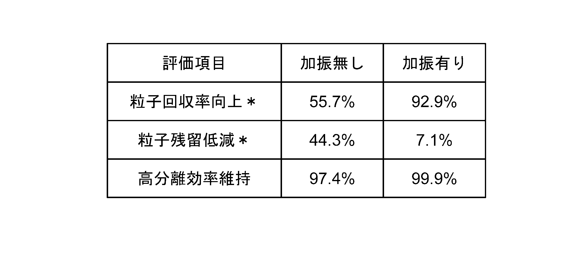
図15Aは、ろ室、第1排出室及び第2排出室5の内部に振動部材を設置した概略図である。なお、本実施形態では、説明の便宜上、ろ室3側から第1アノード電極13-1、第2アノード電極13-2、第3アノード電極13-3、第4アノード電極13-4としている。図15Aに基づいて、濃縮物45側の電界において、圧電振動子に順次ON/OFFスイッチング機能の追加した試験例を説明する。
本試験例では、濃縮側(+)の第1アノード電源201-1、第2アノード電源201-2、第3アノード電源201-3に、マイコン制御リレーを装着して順次ON/OFFのスイッチングモード運転を可能とした。(+)電極間に滞留した(-)帯電の濃縮粒子を順次電界OFFにすることで解放するタイミングを設けて排出させ堆積を防止するようにしている。
(+)電極間に滞留した(-)帯電の濃縮粒子を順次電界OFFにすることで解放するタイミングを設けて排出させ、微粒子の堆積を防止した。
本試験例の粒子42はマイナス側に帯電しているとする。
電極間において、電位差があっても、10Vの電位差の場合では、少し粒子42が電極に付着する。
例えば第1アノード電極13-1の電位を+20Vとし、第2電極13-2の電位を+30Vとし、第3電極13-3の電位を+40Vとし、第4電極13-4の電位を+50Vとする。
このような場合、第2アノード電極13-2~第4アノード電極13-4において、第1アノード電源13-1~第3アノード電源13-3のスイッチングのON-OFFを順次繰り返す。
通常、第2アノード電極13-2をONとして、第2アノード電極13-2に+30Vを印加すると、第3アノード電極13-3(+40V)との電位差は+10Vとなる。
この際、スイッチングにより第2アノード電極13-2をOFFとすると、第1アノード電極13-1側と導通して、第2アノード電極13-2の電位が+20Vとなる。この結果、第3アノード電極13-3は通常+40Vであるので、第2アノード電極がOFFのときの第3アノード電極13-3との電位差は、常時ONのときの電位差+10Vに対して、電位差が+20Vと倍になる。
本実施形態では粒子42がマイナス帯電なので、第3電極13-3側に引き寄せられる粒子引き寄せ効果が増大する。
第2アノード電極13-2~第アノード4電極13-4は2秒ONとして1秒OFFを繰り返すようにしている。なお、このスイッチング時間は適宜変更することができる。

図16は、実施形態7のろ過システムを模式的に示す図である。ろ過システム100は、ろ過装置1にスラリー40を供給して固液分離を行い、濃縮物44とろ液45を回収するシステムである。また、ろ過装置1による固液分離は、バッチ処理でなく連続処理である。よって、ろ過システム100において、スラリー40の供給を継続して行い、濃縮物44とろ液45の回収も継続して行うことができる装置である。
また、粒子によっては、pHによって帯電状態が変化するものもある。
また、液体の水分子41は、この水分子41に分散されている粒子42がマイナス(-)に帯電している場合、粒子42を分散させている液体の水分子41は見かけ上(+)プラスに挙動する。
これに対して、液体の水分子41に分散されている粒子がプラス(+)に帯電している場合、粒子42を分散させている液体の水分子41は見かけ上(-)マイナスに挙動する。
その他の構成は実施形態1のろ過装置1と同一であるので、その説明は省略する。
また、密閉容器2の内部からガス47が除去される。また、循環ライン103により抜き取られたスラリー40は、貯留槽101に循環して放熱する。一方で、密閉容器2の内部に残ったスラリー40には、多くのスラリー40が供給され冷却する。よって、スラリー40の温度上昇が抑制される。
複数の電極10は、ろ室3と第1排出室4とを仕切る複数のカソード電極と、ろ室3と第2排出室5とを仕切る複数のアノード電極と、を有する。複数のカソード電極は、カソード第1電極11と、カソード第1電極11よりも第1排出室4寄りに配置されたカソード第2電極12と、を有する。複数のアノード電極は、ろ室3を挟んでカソード第1電極11と対向するアノード第1電極13と、アノード第1電極13よりも第2排出室5寄りに配置されたアノード第2電極14と、を有する。カソード第1電極11には、粒子の極性と同じ極性のカソード第1電位V1が供給される。カソード第2電極12には、粒子の極性と同じ極性のカソード第2電位V2が供給される。カソード第2電位V2の絶対値は、カソード第1電位V1の絶対値よりも大きい。アノード第1電極13には、粒子の極性と異なる極性のアノード第1電位V11が供給される。アノード第2電極14には、粒子の極性と異なる極性のアノード第2電位V12が供給される。アノード第2電位V12の絶対値は、アノード第1電位V11の絶対値よりも大きい。
なお、本実施形態では、分離物としては、第1排出室4にろ室3のスラリー40から分離されるろ液45であり、第2排出室5にろ室3のスラリー40から分離される濃縮物44である。
図18は、実施形態8のろ過システムを模式的に示す図である。図18に示すように、実施形態8では、ろ過システム100に代えてろ過システム100Aを備える点で、実施形態7と相違する。また、実施形態8のろ過システム100Aは、コンプレッサ110、洗浄水槽111、洗浄排水ライン120と、ガス抜き弁(122、132、142)を備えている点で、実施形態7と相違する。また、実施形態8のろ過システム100Aは、供給ポンプ104を備えていない点を実施形態7のろ過システム100と相違する。以下、相違点に絞って説明する。
なお、コンプレッサ110の代わりとしては、例えばガスボンベなどの加圧手段を用いるようにしても良い。
次に実施形態8のろ過システム100Aの使用方法について説明する。
図22は、実施形態9ろ過システムを模式的に示す図である。実施形態9のろ過システム100Bは、供給ポンプ104を備えていない点で実施形態7と相違する。また、実施形態9のろ過システム100Bは、貯留槽101が密閉されている点で、実施形態7と相違する。また、実施形態9のろ過システム100Bは、貯留槽101に圧力調整弁101bが設けられている点で、実施形態7と相違する。また、実施形態9のろ過システム100Bは、エアコンプレッサ110を備えている点で、実施形態7と相違する。
図23は、実施形態10のろ過システムを模式的に示す図である。実施形態10のろ過システム100Cは、図23に示すように、ろ室3の加圧状態を一定に保持するために、
圧力調整ライン128を設置し、圧力調整ライン128に背圧弁(圧力調整弁)129を設置している。この背圧弁129は、例えば0.05MPaに設定し、それ以上となると圧力を逃がす機能を備えている。これにより、定圧ろ過を保持している。
ここで、理想的なろ過システムの流量を想定すると、ライン102で供給するスラリー40を定量ポンプ104で例えば「3」の流量を供給すると仮定する。この際、例えばろ液45の排出量を「1」、濃縮物44の排出量「1」とし、循環の流量を「1」とすることで、バランスするのが理想的である。しかしながら、実際の運転条件は、種々の要因によりこの理想的なバランスで維持することはできない。
図24は、実施形態11のろ過システムを模式的に示す図である。実施形態11のろ過システム100Dは、図24に示すように、ろ室3、第1排出室4、又は第2排出室5の内部の少なくとも一か所に加振部材200を備えるものである。
実施形態11のろ過システム100Dは、電界ろ過においては、強い凝集性を示す粒子42を含むスラリー40を分離場合、ろ室3内及び第1アノード電極13-1、第2アノード電極13-2、第3アノード電極13-3、第4アノード電極13-4間に粒子42の滞留や付着が発生し、粒子42の回収率の低下傾向があるが、加振部材200を設けることにより、これらが解消される。詳細は、実施形態6で説明しているので、その説明は省略する。
図25Aは、実施形態12のろ過システムを模式的に示す図である。実施形態12のろ過システム100E-1は、図25Aに示すように、粒子42と、粒子42の電荷(+)と異なる電荷(-)を帯びている媒体(水分子41)とを含むスラリー40が供給されるろ室3と、ろ室3の両側面に対向して設けられ、スラリー40中の粒子42と媒体(水分子41)とを電気的に分離する第1分離電極群10Aと第2分離電極群10Bと、第1分離電極群10Aと第2分離電極群10Bのろ室と反対側に設けられ、分離物(媒体(水分子41)、粒子42)を排出するカソード側第1排出室4とアノード側第2排出室5と、を備えた、ろ過装置ユニットを一単位のモジュールとし、ろ過装置ユニット160(160-1,160-2…)からなるモジュールを連結する際、連結チャンバー161を用いて複数連結している。
本実施形態では、第2排出室5を共用している。
なお、さらに連結する場合には、ろ過装置ユニット160-2の隣にろ過装置ユニット160-3(図示せず)を設け、第1排出室4を共用とするようにすればよい。
図26は、実施形態13のろ過システムを模式的に示す図である。
また、図28は、実施形態7のろ過装置のろ過装置を模式的に示す模式図であり、図17と同一である。図29は、実施形態13のろ過装置のろ過装置を模式的に示す模式図である。図31は、実施形態13,14の電源構成を示す回路図であり、図31Aは並列回路図、図31Bは直列回路図である。
図26に示すように、実施形態13のろ過システム100Eは、相異なる電荷を帯びている粒子(+)42と液体(水分子(-)41)とを、含むスラリー40が、供給ライン(管)102により供給されるろ室3と、ろ室3の両側面に、相対向して設けられ、スラリー40中の粒子42と液体(水分子41)とを電界作用によって分離する少なくとも2以上のカソード電極又はアノード電極のいずれか一方又は両方を備えた第1電極群10A、第2電極群10Bと、電極群のろ室3と反対側に設けられ、分離物である濃縮物44とろ液45とを排出する第1排出室4および第2排出室5とを備えたろ過装置1Gとしている。
そして、第1電極群10A、第2電極群10Bが、同極性のカソード側とし、電極群を構成する電極が細孔を有すると共に、電極群10A、10Bの極性(-)と異なる極性(+)のアノード側の電極170Aをろ室3内に配置するものである。
前述したように、図17に示す実施形態7のろ過装置1Fでは、図28に示すように、ろ過室3の左右に第1排出室4、第2排出室5を各々設置している。この結果、ろ室3に供給されたスラリー40は、ろ室3を中心として左右に相対向する第1電極群10A(11、12)、第2電極群10B(13、14)における電界作用により分離され、ろ液45は第1排出室4に、濃縮物44は第2排出室5に分離されている。
図27は、実施形態14のろ過システムを模式的に示す図である。図30は、実施形態14のろ過装置のろ過装置を模式的に示す模式図である。
図27に示すように、実施形態14のろ過システム100Fは、相異なる電荷を帯びている粒子(+)42と液体(水分子(-)41)とを、含むスラリー40が、供給ライン(管)102により供給されるろ室3と、ろ室3の両側面に、相対向して設けられ、スラリー40中の粒子42と液体(水分子41)とを電界作用によって分離する少なくとも2以上のカソード電極又はアノード電極のいずれか一方又は両方を備えた第1電極群10A、第2電極群10Bと、電極群のろ室3と反対側に設けられ、分離物である濃縮物44を排出する第1排出室4及び第2排出室5とを備えており、第1電極群10A、第2電極群10Bが、同極性のアノード側であり、電極群を構成する電極が細孔を有すると共に、電極群の極性(-)と異なる極性(+)のカソード側の電極170Bをろ室3内に配置するものである。
本実施形態では、以下の構成を含む。
(1)
ろ室、第1排出室、及び第2排出室を内部に有する密閉容器と、
帯電した粒子と液体が混合したスラリーを供給する供給ラインと、
前記供給ラインと前記ろ室を連通する供給口と、
前記液体を前記第1排出室から排出する第1排出口と、
前記スラリーから前記液体が分離した濃縮物を前記第2排出室から排出する第2排出口と、
前記粒子及び前記液体が通過可能な複数の孔が設けられた複数の電極と、
を備え、
前記複数の電極は、
前記ろ室と前記第1排出室とを仕切る複数のカソード電極と、
前記ろ室と前記第2排出室とを仕切る複数のアノード電極と、
を有し、
前記複数のカソード電極は、
カソード第1電極と、
前記カソード第1電極よりも前記第1排出室寄りに配置されたカソード第2電極と、
を有し、
前記複数のアノード電極は、
前記ろ室を挟んで前記カソード第1電極と対向するアノード第1電極と、
前記アノード第1電極よりも前記第2排出室寄りに配置されたアノード第2電極と、
を有し、
前記カソード第1電極には、前記粒子の極性と同じ極性のカソード第1電位が供給され、
前記カソード第2電極には、前記粒子の極性と同じ極性のカソード第2電位が供給され、
前記カソード第2電位の絶対値は、前記カソード第1電位の絶対値よりも大きく、
前記アノード第1電極には、前記粒子の極性と異なる極性のアノード第1電位が供給され、
前記アノード第2電極には、前記粒子の極性と異なる極性のアノード第2電位が供給され、
前記アノード第2電位の絶対値は、前記アノード第1電位の絶対値よりも大きい
ろ過装置。
(2)
前記複数のカソード電極は、3つ以上の電極を有し、
前記複数のカソード電極のそれぞれに供給されるカソード電位の絶対値は、前記ろ室から離隔するにつれて大きい
(1)に記載のろ過装置。
(3)
前記複数のアノード電極は、3つ以上の電極を有し、
前記複数のアノード電極のそれぞれに供給されるアノード電位の絶対値は、前記ろ室から離隔するにつれて大きい
(1)又は(2)に記載のろ過装置。
(4)
前記複数のカソード電極の間に、ろ材が設けられている
(1)又は(2)に記載のろ過装置。
(5)
前記複数のアノード電極の間に、複数の孔が設けられた誘電体が設けられている
(1)又は(2)に記載のろ過装置。
(6)
前記誘電体の前記孔の径は、1000nm以上4000nm以下である
(5)に記載のろ過装置。
(7)
さらに、ブリーダ抵抗を備え、
一端が前記ブリーダ抵抗と接続する第1電気配線と、
一端が前記ブリーダ抵抗と接続する第2電気配線と、
を有し、
前記第1電気配線の他端は、前記複数のカソード電極のうち前記ろ室から最も離隔する前記電極と接続し、
前記第2電気配線の他端は、前記複数のアノード電極のうち前記ろ室から最も離隔する前記電極と接続する
(1)又は(2)に記載のろ過装置。
(8)
前記第1排出室と前記第2排出室に配置される中和電極と、
前記粒子の極性と異なる極性の中和電位を前記中和電極に供給する中和電源と、
を備え、
前記中和電位の絶対値は、前記複数のアノード電極のうち前記ろ室から最も離隔する前記電極に供給されるアノード電位の絶対値よりも大きい
(1)又は(2)に記載のろ過装置。
(9)
前記電極の表面には、電食防止層が設けられている
(1)又は(2)に記載のろ過装置。
(10)
前記供給ラインの内部にある前記スラリーを前記ろ室の方に押し出すポンプ)を備える
(1)又は(2)に記載のろ過装置。
(11)
前記複数のカソード電極にカソード電位を供給する複数のカソード電源と、
前記複数のアノード電極にアノード電位を供給する複数のアノード電源と、
を備える
(1)又は(2)に記載のろ過装置。
(12)
鉛直方向の上方から前記第1排出室、前記ろ室、前記第2排出室の順で配置される
(1)又は(2)に記載のろ過装置。
(13)
前記複数のアノード電極の間に発生する電界の力を前記ろ室のろ過圧力よりも小さくなるように、前記複数のアノード電極に供給するアノード電位を設定する
(1)又は(2)に記載のろ過装置の運転方法。
(14)
前記複数のアノード電極の間に発生する電界の力を前記ろ室のろ過圧力よりも大きくした後、前記電界の力が前記ろ室の過圧力よりも小さくなるように、前記複数のアノード電極に供給するアノード電位を変更する(1)又は(2)に記載のろ過装置の運転方法。
(15)
帯電した粒子と液体が混合されたスラリーを貯留する貯留槽と、
内部に電極が設けられた密閉容器を有し、前記密閉容器の内部で前記スラリーの固液分離を連続して行うろ過装置と、
前記貯留槽から前記密閉容器の内部に前記スラリーを継続的に供給する供給ラインと、
前記密閉容器の内部から前記スラリーの一部を抜き取り、前記貯留槽に継続的に循環させる循環ラインと、
前記循環ラインに設けられ、前記循環ラインを流れる前記スラリーの単位時間当たりの循環量を、前記供給ラインを流れる前記スラリーの単位時間当たりの供給量よりも少なく調整する定量ポンプと、
を備えるろ過システム。
(16)
前記循環ラインは、前記密閉容器の上部から前記スラリーを抜き取っている
(15)に記載のろ過システム。
(17)
前記循環ラインには、ガス抜き弁が設けられている
(15)又は(16)に記載のろ過システム。
(18)
前記ろ過装置は、
ろ室、第1排出室、及び第2排出室を内部に有する前記密閉容器と、
前記供給ラインと前記ろ室を連通する供給口と、
前記液体を前記第1排出室から排出する第1排出口と、
前記スラリーから前記液体が分離した濃縮物を前記第2排出室から排出する第2排出口と、
前記粒子及び前記液体が通過可能な複数の孔が設けられた複数の前記電極と、
を備え、
複数の前記電極は、
前記ろ室と前記第1排出室とを仕切る複数のカソード電極と、
前記ろ室と前記第2排出室とを仕切る複数のアノード電極と、
を有し、
前記複数のカソード電極は、
カソード第1電極と、
前記カソード第1電極よりも前記第1排出室寄りに配置されたカソード第2電極と、
を有し、
前記複数のアノード電極は、
前記ろ室を挟んで前記カソード第1電極と対向するアノード第1電極と、
前記アノード第1電極よりも前記第2排出室寄りに配置されたアノード第2電極と、
を有し、
前記カソード第1電極には、前記粒子の極性と同じ極性のカソード第1電位が供給され、
前記カソード第2電極には、前記粒子の極性と同じ極性のカソード第2電位が供給され、
前記カソード第2電位の絶対値は、前記カソード第1電位の絶対値よりも大きく、
前記アノード第1電極には、前記粒子の極性と異なる極性のアノード第1電位が供給され、
前記アノード第2電極には、前記粒子の極性と異なる極性のアノード第2電位が供給され、
前記アノード第2電位の絶対値は、前記アノード第1電位の絶対値よりも大きい
(15)又は(16)に記載のろ過システム。
(19)
前記ろ室、前記第1排出室、及び前記第2排出室は、水平方向に配置され、
前記密閉容器は、前記ろ室の上部と前記循環ラインとを連通する取り出し口を有している (18)に記載のろ過システム。
(20)
前記第1排出口は、前記第1排出室の上部から前記液体を排出する
(19)に記載のろ過システム。
(21)
前記第2排出口は、前記第2排出室の上部から前記液体を排出する
(19)に記載のろ過システム。
(22)
前記第1排出口に接続する第1排出ラインと、
前記第2排出口に接続する第2排出ラインと、
を備え、
前記第1排出ライン及び前記第2排出ラインには、ガス抜き弁が設けられている
(18)に記載のろ過システム。
(23)
前記複数のカソード電極は、3つ以上の電極を有し、
前記複数のカソード電極のそれぞれに供給されるカソード電位の絶対値は、前記ろ室から離隔するにつれて大きくなる
(18)に記載のろ過システム。
(24)
前記複数のアノード電極は、3つ以上の電極を有し、
前記複数のアノード電極のそれぞれに供給されるアノード電位の絶対値は、前記ろ室から離隔するにつれて大きくなる
(18)に記載のろ過システム。
2 密閉容器
3 ろ室
3a 供給口
4 第1排出室
4a 第1排出口
5 第2排出室
5a 第2排出口
6 連通口
7 ろ材
8 誘電体
10 電極
10a 孔
11 カソード第1電極
12 カソード第2電極
13 アノード第1電極
14 アノード第2電極
15 カソード第3電極
16 アノード第3電極
20 電源
21 カソード第1電源
22 カソード第2電源
23 アノード第1電源
24 アノード第2電源
25 カソード第3電源
26 アノード第3電源
40 スラリー
41 水分子
42 粒子
44 濃縮物
45 ろ液
50 ブリーダ抵抗
51 第1電気配線
52 第2電気配線
60 中和電極
61 第1中和電極
62 第2中和電極
63 中和電源
S 密閉空間
Ea アノード電界
Ec カソード電界
100、100A~G ろ過システム
101 貯留槽
102 供給ライン
103 循環ライン
104 供給ポンプ
106 循環ポンプ
110 コンプレッサ
111 洗浄水槽
116 取り出し口
120 洗浄排水ライン
122 第1ガス抜き弁
128 圧力調整ライン
129 背圧弁
132 第2ガス抜き弁
142 第3ガス抜き弁
101a 開口部
101b 圧力調整弁
160 ろ過装置ユニット
161 連結チャンバー
170A アノード電極
170B カソード電極
Claims (16)
- 相異なる電荷を帯びている粒子と液体とを含むスラリーが、供給ラインにより供給されるろ室と、
前記ろ室の両側面に、相対向して設けられ、前記スラリー中の粒子と液体とを電界作用によって分離物として分離するカソード電極又はアノード電極を備えた第1電極群又は第2電極群と、
前記第1電極群、前記第2電極群に対して、前記ろ室と相対向して設けられ、前記分離物を排出する第1排出室及び第2排出室とを備える
ろ過装置。 - 電極群の極性が、異なり、
前記電極群を構成する電極が細孔を有する
請求項1に記載のろ過装置。 - 電極群が、同極性であり、
電極群を構成する電極が細孔を有すると共に、
電極群の極性と異なる極性の電極をろ室内に配置する
請求項1に記載のろ過装置。 - ろ室と排出室との間の電極群は
ろ室側から排出室側にいくに従って、
排出室側の電位の絶対値は、ろ室側の電位の絶対値よりも大きな勾配を有する
請求項1に記載のろ過装置。 - ろ室、第1排出室、又は第2排出室の内部の少なくとも一か所に加振部材を備える
請求項1に記載のろ過装置 - 前記ろ過装置からなるユニットを一単位のモジュールとし、
前記ろ過装置ユニットモジュールを連結チャンバーで複数連結してなる、
請求項1に記載のろ過装置。 - 前記ろ過装置からなるユニット一単位のモジュールとし、
前記ろ過装置ユニットからなるモジュールを連結する際、
第1排出室又は第2排出室のいずれか一方を共用化してなる、
請求項1に記載のろ過装置。 - 帯電した粒子と液体が混合されたスラリーを貯留する貯留槽と、
内部に複数のカソード電極と複数のアノード電極とが設けられた密閉容器を有し、前記密閉容器の内部で前記スラリーの固液分離を連続して行うろ過装置と、
前記貯留槽から前記密閉容器の内部に前記スラリーを継続的に供給する供給ラインと、
前記密閉容器の内部から前記スラリーの一部を抜き取り、前記貯留槽に継続的に循環させる循環ラインと、
前記循環ラインに設けられ、前記循環ラインを流れる前記スラリーの単位時間当たりの循環量を、前記供給ラインを流れる前記スラリーの単位時間当たりの供給量よりも少なく調整する定量ポンプと、
を備えるろ過システム。 - 前記供給ラインは、前記密閉容器の一側面側に接続され、前記密閉容器内にスラリーを供給すると共に、
前記循環ラインは、前記密閉容器の一側面側と対向する側面側から前記スラリーを抜き取っている
請求項8に記載のろ過システム。 - 前記ろ過装置は、
相異なる電荷を帯びている粒子と液体とを含むスラリーが、供給ラインにより供給されるろ室と、
前記ろ室の両側面に、相対向して設けられ、
前記スラリー中の粒子と液体とを電界作用によって分離物として分離するカソード電極又はアノード電極を備えた第1電極群又は第2電極群と、
前記第1電極群、前記第2電極群に対して、前記ろ室と相対向して設けられ、前記分離物を排出する第1排出室及び第2排出室とを備える、
請求項8に記載のろ過システム。 - 前記電極群の極性が、異なり、
前記電極群を構成する電極が細孔を有する
請求項10に記載のろ過システム。 - 前記電極群が、同極性であり、
前記電極群を構成する電極が細孔を有すると共に、
前記電極群の極性と異なる極性の電極をろ室内に配置する
請求項10に記載のろ過システム。 - 前記第1排出口に接続する第1排出ラインと、
前記第2排出口に接続する第2排出ラインと、
を備え、
前記循環ライン又は前記第1排出ライン又は前記第2排出ラインの少なくとも一つに、ガス抜き弁が設けられている
請求項10に記載のろ過システム。 - ろ室、第1排出室、又は第2排出室の内部の少なくとも一か所に加振部材を備える
請求項8に記載のろ過システム。 - 前記ろ過装置は、
ろ室の両側面に、相対向して設けられ、相異なる電荷を帯びている粒子と液体とを含むスラリーが、供給ラインにより供給されるろ室と、
前記ろ室の両側面に、相対向して設けられ、前記スラリー中の粒子と液体とを電界作用によって分離物として分離するカソード電極又はアノード電極を備えた第1電極群又は第2電極群と、
前記第1電極群、前記第2電極群に対して、前記ろ室と相対向して設けられ、前記分離物を排出する第1排出室及び第2排出室とを備えて、ろ過装置ユニットとし、
前記ろ過装置ユニットを一単位のモジュールとし、
前記ろ過装置ユニットモジュールを連結チャンバーで複数連結してなる、
請求項8に記載のろ過システム。 - 前記ろ過装置は、
相異なる電荷を帯びている粒子と液体とを含むスラリーが、供給ラインにより供給されるろ室と、
ろ室の両側面に、相対向して設けられ、前記スラリー中の粒子と液体とを電界作用によって分離物として分離するカソード電極又はアノード電極を備えた第1電極群又は第2電極群と、
前記第1電極群、前記第2電極群に対して、前記ろ室と相対向して設けられ、前記分離物を排出する第1排出室及び第2排出室とを備えて、ろ過装置ユニットとし、
前記ろ過装置ユニットからなるモジュールを連結する際、前記第1排出室又は前記第2排出室のいずれか一方を共用化してなる、
請求項8に記載のろ過システム。
Priority Applications (3)
| Application Number | Priority Date | Filing Date | Title |
|---|---|---|---|
| JP2023533704A JP7399604B2 (ja) | 2021-11-05 | 2022-11-04 | ろ過装置及びろ過システム |
| AU2022382441A AU2022382441A1 (en) | 2021-11-05 | 2022-11-04 | Filtration device, and filtration system |
| CA3237111A CA3237111A1 (en) | 2021-11-05 | 2022-11-04 | Filtration device and filtration system |
Applications Claiming Priority (4)
| Application Number | Priority Date | Filing Date | Title |
|---|---|---|---|
| JPPCT/JP2021/040863 | 2021-11-05 | ||
| PCT/JP2021/040863 WO2023079708A1 (ja) | 2021-11-05 | 2021-11-05 | ろ過装置及びろ過装置の運転方法 |
| JP2022027233 | 2022-02-24 | ||
| JP2022-027233 | 2022-02-24 |
Publications (1)
| Publication Number | Publication Date |
|---|---|
| WO2023080199A1 true WO2023080199A1 (ja) | 2023-05-11 |
Family
ID=86241555
Family Applications (1)
| Application Number | Title | Priority Date | Filing Date |
|---|---|---|---|
| PCT/JP2022/041153 WO2023080199A1 (ja) | 2021-11-05 | 2022-11-04 | ろ過装置及びろ過システム |
Country Status (5)
| Country | Link |
|---|---|
| JP (1) | JP7399604B2 (ja) |
| AU (1) | AU2022382441A1 (ja) |
| CA (1) | CA3237111A1 (ja) |
| TW (1) | TW202335723A (ja) |
| WO (1) | WO2023080199A1 (ja) |
Citations (10)
| Publication number | Priority date | Publication date | Assignee | Title |
|---|---|---|---|---|
| US4468306A (en) * | 1983-04-06 | 1984-08-28 | Dorr-Oliver Incorporated | Biodic electrofiltration |
| JPS6118410A (ja) * | 1984-07-04 | 1986-01-27 | Fuji Electric Corp Res & Dev Ltd | 電気浸透式脱水機の運転制御方法 |
| JPS61161108A (ja) * | 1984-12-31 | 1986-07-21 | ドル‐オリバー インコーポレイテツド | 改良電極体を使用する電気フイルター装置 |
| JPS62183860A (ja) * | 1986-02-07 | 1987-08-12 | Mitsubishi Heavy Ind Ltd | 湿式電気集じん装置の洗滌水循環方法 |
| US4755305A (en) * | 1982-03-15 | 1988-07-05 | Champion International Corporation | Continuous dewatering method |
| JPH078715A (ja) * | 1993-04-28 | 1995-01-13 | Dengiyoushiya Kikai Seisakusho:Kk | 密閉式脱水ろ過機 |
| JP2002023583A (ja) * | 2000-07-10 | 2002-01-23 | Mitsubishi Heavy Ind Ltd | 液体トナーの再生装置及び再生方法 |
| JP2006506223A (ja) * | 2002-11-18 | 2006-02-23 | バイエル・テクノロジー・サービシーズ・ゲゼルシャフト・ミット・ベシュレンクテル・ハフツング | 分取法として電気泳動を実施するための装置および方法 |
| JP2015202481A (ja) * | 2014-04-16 | 2015-11-16 | 栗田工業株式会社 | 電気浸透脱水装置 |
| JP2017056397A (ja) * | 2015-09-15 | 2017-03-23 | 株式会社東芝 | 電解水供給システム |
-
2022
- 2022-11-04 TW TW111142186A patent/TW202335723A/zh unknown
- 2022-11-04 CA CA3237111A patent/CA3237111A1/en active Pending
- 2022-11-04 WO PCT/JP2022/041153 patent/WO2023080199A1/ja active Application Filing
- 2022-11-04 AU AU2022382441A patent/AU2022382441A1/en active Pending
- 2022-11-04 JP JP2023533704A patent/JP7399604B2/ja active Active
Patent Citations (10)
| Publication number | Priority date | Publication date | Assignee | Title |
|---|---|---|---|---|
| US4755305A (en) * | 1982-03-15 | 1988-07-05 | Champion International Corporation | Continuous dewatering method |
| US4468306A (en) * | 1983-04-06 | 1984-08-28 | Dorr-Oliver Incorporated | Biodic electrofiltration |
| JPS6118410A (ja) * | 1984-07-04 | 1986-01-27 | Fuji Electric Corp Res & Dev Ltd | 電気浸透式脱水機の運転制御方法 |
| JPS61161108A (ja) * | 1984-12-31 | 1986-07-21 | ドル‐オリバー インコーポレイテツド | 改良電極体を使用する電気フイルター装置 |
| JPS62183860A (ja) * | 1986-02-07 | 1987-08-12 | Mitsubishi Heavy Ind Ltd | 湿式電気集じん装置の洗滌水循環方法 |
| JPH078715A (ja) * | 1993-04-28 | 1995-01-13 | Dengiyoushiya Kikai Seisakusho:Kk | 密閉式脱水ろ過機 |
| JP2002023583A (ja) * | 2000-07-10 | 2002-01-23 | Mitsubishi Heavy Ind Ltd | 液体トナーの再生装置及び再生方法 |
| JP2006506223A (ja) * | 2002-11-18 | 2006-02-23 | バイエル・テクノロジー・サービシーズ・ゲゼルシャフト・ミット・ベシュレンクテル・ハフツング | 分取法として電気泳動を実施するための装置および方法 |
| JP2015202481A (ja) * | 2014-04-16 | 2015-11-16 | 栗田工業株式会社 | 電気浸透脱水装置 |
| JP2017056397A (ja) * | 2015-09-15 | 2017-03-23 | 株式会社東芝 | 電解水供給システム |
Also Published As
| Publication number | Publication date |
|---|---|
| JPWO2023080199A1 (ja) | 2023-05-11 |
| AU2022382441A1 (en) | 2024-05-23 |
| TW202335723A (zh) | 2023-09-16 |
| JP7399604B2 (ja) | 2023-12-18 |
| CA3237111A1 (en) | 2023-05-11 |
Similar Documents
| Publication | Publication Date | Title |
|---|---|---|
| US4207158A (en) | Electrically augmented vacuum filtration | |
| CN106178636B (zh) | 用于过滤和滤饼层形成的方法和系统 | |
| CN103130363B (zh) | 脱盐系统和方法 | |
| CN105271615B (zh) | 电化学复合式膜生物反应器 | |
| WO2023080199A1 (ja) | ろ過装置及びろ過システム | |
| CN2936380Y (zh) | 气浮冲洗式活性砂连续自动过滤器 | |
| JPWO2023080199A5 (ja) | ||
| CN210419570U (zh) | 一种煤化工废水气浮除油装置 | |
| Wickramasinghe et al. | Enhanced microfiltration of yeast by flocculation | |
| WO2023079708A1 (ja) | ろ過装置及びろ過装置の運転方法 | |
| JP7117471B1 (ja) | ろ過装置及びろ過システム | |
| JP7308368B2 (ja) | ろ過装置 | |
| WO2022091364A1 (ja) | ろ過装置 | |
| TWI834103B (zh) | 過濾裝置 | |
| JP2001517142A (ja) | 夾雑物を含有する液体を精製する方法および装置 | |
| CN109553241B (zh) | 一种含油污水处理装置及方法 | |
| WO2022070281A1 (ja) | ろ過装置 | |
| JP7474866B2 (ja) | ろ過装置 | |
| WO2022091363A1 (ja) | ろ過システム及びろ過装置 | |
| JP2005074316A (ja) | コンプレッサードレンの処理装置 | |
| WO2022130489A1 (ja) | ろ過装置 | |
| CN216584325U (zh) | 悬浮物固液分离装置 | |
| WO2022070280A1 (ja) | ろ過装置 | |
| CN114275859A (zh) | 悬浮物固液分离装置及方法 | |
| JP2003260306A (ja) | 油水分離方法及び装置 |
Legal Events
| Date | Code | Title | Description |
|---|---|---|---|
| WWE | Wipo information: entry into national phase |
Ref document number: 2023533704 Country of ref document: JP |
|
| 121 | Ep: the epo has been informed by wipo that ep was designated in this application |
Ref document number: 22890019 Country of ref document: EP Kind code of ref document: A1 |
|
| ENP | Entry into the national phase |
Ref document number: 3237111 Country of ref document: CA |
|
| ENP | Entry into the national phase |
Ref document number: 2022382441 Country of ref document: AU Date of ref document: 20221104 Kind code of ref document: A |