WO2023080190A1 - 積層造形体の寸法品質評価方法及びその評価システム - Google Patents
積層造形体の寸法品質評価方法及びその評価システム Download PDFInfo
- Publication number
- WO2023080190A1 WO2023080190A1 PCT/JP2022/041118 JP2022041118W WO2023080190A1 WO 2023080190 A1 WO2023080190 A1 WO 2023080190A1 JP 2022041118 W JP2022041118 W JP 2022041118W WO 2023080190 A1 WO2023080190 A1 WO 2023080190A1
- Authority
- WO
- WIPO (PCT)
- Prior art keywords
- sample
- laminate
- dimensional quality
- deformation
- dimensional
- Prior art date
- Legal status (The legal status is an assumption and is not a legal conclusion. Google has not performed a legal analysis and makes no representation as to the accuracy of the status listed.)
- Ceased
Links
Images





Classifications
-
- B—PERFORMING OPERATIONS; TRANSPORTING
- B29—WORKING OF PLASTICS; WORKING OF SUBSTANCES IN A PLASTIC STATE IN GENERAL
- B29C—SHAPING OR JOINING OF PLASTICS; SHAPING OF MATERIAL IN A PLASTIC STATE, NOT OTHERWISE PROVIDED FOR; AFTER-TREATMENT OF THE SHAPED PRODUCTS, e.g. REPAIRING
- B29C64/00—Additive manufacturing, i.e. manufacturing of three-dimensional [3D] objects by additive deposition, additive agglomeration or additive layering, e.g. by 3D printing, stereolithography or selective laser sintering
- B29C64/30—Auxiliary operations or equipment
- B29C64/386—Data acquisition or data processing for additive manufacturing
- B29C64/393—Data acquisition or data processing for additive manufacturing for controlling or regulating additive manufacturing processes
-
- B—PERFORMING OPERATIONS; TRANSPORTING
- B33—ADDITIVE MANUFACTURING TECHNOLOGY
- B33Y—ADDITIVE MANUFACTURING, i.e. MANUFACTURING OF THREE-DIMENSIONAL [3D] OBJECTS BY ADDITIVE DEPOSITION, ADDITIVE AGGLOMERATION OR ADDITIVE LAYERING, e.g. BY 3D PRINTING, STEREOLITHOGRAPHY OR SELECTIVE LASER SINTERING
- B33Y50/00—Data acquisition or data processing for additive manufacturing
- B33Y50/02—Data acquisition or data processing for additive manufacturing for controlling or regulating additive manufacturing processes
-
- G—PHYSICS
- G01—MEASURING; TESTING
- G01B—MEASURING LENGTH, THICKNESS OR SIMILAR LINEAR DIMENSIONS; MEASURING ANGLES; MEASURING AREAS; MEASURING IRREGULARITIES OF SURFACES OR CONTOURS
- G01B21/00—Measuring arrangements or details thereof, where the measuring technique is not covered by the other groups of this subclass, unspecified or not relevant
- G01B21/32—Measuring arrangements or details thereof, where the measuring technique is not covered by the other groups of this subclass, unspecified or not relevant for measuring the deformation in a solid
-
- Y—GENERAL TAGGING OF NEW TECHNOLOGICAL DEVELOPMENTS; GENERAL TAGGING OF CROSS-SECTIONAL TECHNOLOGIES SPANNING OVER SEVERAL SECTIONS OF THE IPC; TECHNICAL SUBJECTS COVERED BY FORMER USPC CROSS-REFERENCE ART COLLECTIONS [XRACs] AND DIGESTS
- Y02—TECHNOLOGIES OR APPLICATIONS FOR MITIGATION OR ADAPTATION AGAINST CLIMATE CHANGE
- Y02P—CLIMATE CHANGE MITIGATION TECHNOLOGIES IN THE PRODUCTION OR PROCESSING OF GOODS
- Y02P10/00—Technologies related to metal processing
- Y02P10/25—Process efficiency
Definitions
- the present invention relates to a method of evaluating the dimensional quality of a laminate-molded body and an evaluation system thereof.
- Additive manufacturing manufactures a three-dimensional object (modeled object) by stacking and combining molding materials such as resin and metal multiple times in small volume units. It is a processing technology that Laminate manufacturing is characterized by the fact that it is possible to manufacture even a modeled object having a complicated shape, such as one having a space inside, at substantially constant time and cost. Because of this feature, additive manufacturing is being used to manufacture products with complex structures that have been difficult to achieve with conventional processing technology due to manufacturing time and cost constraints.
- laminate-manufactured products hereinafter also referred to as “laminate-manufactured products” is that they have a three-dimensionally intricate and complicated structure in order to achieve higher performance than conventional products.
- Dimensional quality is one of the important qualities of industrial products, but it is especially important for additive manufacturing that achieves high performance with a complex structure.
- a plurality of prior arts are known as methods for evaluating the dimensional quality of a layered product.
- Japanese Patent Laid-Open No. 2002-200000 describes preparing a plurality of sample shapes and shape errors measured by molding the plurality of samples in advance, preparing a molding apparatus capable of detecting the shape of a molded object during molding, and using the molding apparatus.
- a technique for detecting the shape of a product while molding the product, comparing the design shape of the product and the detected shape of the product with the sample shape and its shape error, and evaluating the shape error of the product is disclosed. According to the technique disclosed in Patent Literature 1, layered manufacturing can be performed with higher accuracy by evaluating the shape error of the product and changing the next operation of the modeling apparatus.
- Patent Document 2 discloses a technique for predicting shape distortion and residual stress growth in a modeled object by performing finite element analysis with a finite element thermo-mechanical model of the modeled object during and after additive manufacturing. According to the technique disclosed in Patent Literature 2, predicted distortion can be compensated for by introducing changes to the modeled object before or during modeling.
- Patent document 3 prepares a molding apparatus equipped with a monitoring unit that monitors the state of a molded object during molding, and while molding both a product and a quality control sample with the molding apparatus, monitors the state of the quality control sample.
- a technique of monitoring using the monitoring unit is disclosed. Conditions monitored by the monitoring unit include temperature, shape, surface roughness, and color tone. According to the technique disclosed in Patent Document 3, the state of the quality control sample is monitored during molding, and the next operation of the molding apparatus is changed based on the monitoring result, thereby molding a high-quality product. be able to.
- Patent Document 1 has the problem that a plurality of samples are formed in advance, which takes time and reduces productivity. Furthermore, the technique disclosed in Patent Document 1 requires a device with a complicated configuration for accurately detecting the shape of a modeled object during modeling, and requires time and effort to maintain and manage the accuracy of this device. The problem is that it cannot be implemented.
- Patent Document 2 has the problem that it is not possible to evaluate dimensional quality in consideration of the influence of factors not included in the finite element thermo-mechanical model on dimensional quality.
- Factors that are not included in the finite element thermo-mechanical model include, for example, the specifications and arrangement of the parts of the molding apparatus, the components and flow of the atmosphere around the object during molding, and the detailed shape of the molding material. Including these factors in the finite element thermo-mechanical model raises the problem of increased finite element analysis time and reduced productivity. On the other hand, if these factors are not included in the finite element thermo-mechanical model, there is a problem that changes in dimensional quality due to the influence of these factors cannot be evaluated.
- Patent Document 3 requires a complicatedly configured device for accurately monitoring the state of the quality control sample during molding and labor for maintaining and managing the accuracy of this device. The problem is that it cannot be implemented.
- the present invention has been made in view of the above, and an object of the present invention is to provide an evaluation method and an evaluation system that can easily and accurately evaluate the dimensional quality of a laminate-molded body.
- a method for evaluating the dimensional quality of a laminate-molded body of the present invention is a method for evaluating the dimensional quality of a laminate-molded body laminate-molded on a base plate, wherein the dimensional quality of the laminate-molded body A step of laminating a sample for evaluating the lamination-molded body in the same lamination-molding batch as the lamination-molded body on the base plate on which the lamination-molded body is lamination-molded; Deformation of the sample before and after separation from the base plate is measured by obtaining a dimensional difference, separating the laminate-molded sample from the base plate, and measuring the size of the separated sample.
- the deformation of the sample is the reference portion in the sample before being cut off. and a difference value between the dimensional difference of the deformed portion and the dimensional difference between the reference portion and the deformed portion in the separated sample.
- FIG. 4 is a diagram showing the overall steps of the dimensional quality evaluation method of the first embodiment
- FIG. 2(a) is a side view showing the state of the sample and the product after lamination molding.
- 2(b) is a top view of the state shown in FIG. 2(a);
- FIG. Fig.3 (a) is a perspective view which shows the shape of the sample shown to Fig.2 (a) and FIG.2(b).
- FIG. 3(b) is a top view of the sample shown in FIG. 3(a).
- FIG. 3(c) is a side view of the sample shown in FIG. 3(a).
- FIG. 3(d) is a side view of the sample viewed from a direction different from that of FIG. 3(c).
- FIG. 3(a) is a side view showing the state of the sample and the product after lamination molding.
- FIG. Fig.3 (a) is a perspective view which shows the shape of the sample shown to Fig.2 (a) and FIG.2(
- FIG. 4(a) is a side view showing a state in which a base plate before cutting off a comb tooth test piece is placed on a measurement stage.
- FIG. 4(b) is a side view showing a state in which a comb tooth test piece separated from the base plate is placed on the measurement stage.
- FIG. 4(c) is a side view showing a state in which a comb tooth test piece having a shape different from that of FIG. 4(b) is placed on the measurement stage.
- FIG. 4 is a side view showing a state where a sample separated from the base plate is placed on the measurement stage; The figure explaining the modification of a reference
- FIG. 7A is a diagram for explaining a modified example of a sample; FIG.
- FIG. 7(b) is a diagram for explaining a modification of a sample different from that of FIG. 7(a).
- FIG. 7(c) is a diagram for explaining a modification of a sample different from FIGS. 7(a) and 7(b).
- FIG. 8A is a diagram for explaining a modification of the support portion of the deformation portion;
- FIG. 8(b) is a diagram for explaining a modification of the support section different from that of FIG. 8(a).
- FIG. 8(c) is a diagram for explaining a modification of the support section different from FIGS. 8(a) and 8(b).
- FIG. 8A is a diagram for explaining a modification of the support portion of the deformation portion
- FIG. 8(b) is a diagram for explaining a modification of the support section different from that of FIG. 8(a).
- FIG. 8(c) is a diagram for explaining a modification of the support section different from FIGS
- FIG. 4 is a diagram showing a dimensional quality determination table according to the first embodiment
- 1 is a diagram showing the configuration of a dimensional quality evaluation system according to Embodiment 1
- FIG. FIG. 12 is a diagram showing an example of a screen displayed on the terminal device shown in FIG. 11
- FIG. 8 is a diagram showing the overall process of a dimensional quality evaluation method according to Embodiment 2
- the figure which shows the example of a correlation model is a diagram for explaining a technique for constructing the correlation model shown in FIG. 14
- FIG. 10 is a diagram showing a dimensional quality determination table according to the second embodiment
- FIG. 17 is a diagram showing a dimensional quality determination table different from that in FIG. 16
- FIG. 11 is a diagram showing an example of a screen displayed on the terminal device according to the second embodiment
- FIG. 1 A dimensional quality evaluation method and evaluation system for a layered product according to the first embodiment will be described with reference to FIGS. 1 to 12.
- FIG. 1 A dimensional quality evaluation method and evaluation system for a layered product according to the first embodiment will be described with reference to FIGS. 1 to 12.
- FIG. 1 A dimensional quality evaluation method and evaluation system for a layered product according to the first embodiment will be described with reference to FIGS. 1 to 12.
- FIG. 1 A dimensional quality evaluation method and evaluation system for a layered product according to the first embodiment will be described with reference to FIGS. 1 to 12.
- FIG. 1 is a diagram showing the overall process of the dimensional quality evaluation method of Embodiment 1.
- FIG. 1 is a diagram showing the overall process of the dimensional quality evaluation method of Embodiment 1.
- the dimensional quality evaluation method of the present embodiment is a method for evaluating the dimensional quality of the layered product 2 (hereinafter also referred to as "product 2") layered and manufactured on the base plate 3.
- This dimensional quality evaluation method includes a step S1 of laminating and molding a deformation measurement sample 1 (hereinafter also referred to as "sample 1") for evaluating the dimensional quality of the product 2 and the product 2, and a step S1 of laminating and molding the sample 1.
- step S4 of evaluating the dimensional quality of the additive manufacturing batch.
- step S1 the sample 1 is layer-molded simultaneously with the product 2 on the base plate 3 on which the product 2 is layer-molded.
- the additive manufacturing batch in step S4 means a group of objects built in the same additive manufacturing batch, including one or more products 2 and samples 1 . That is, step S4 evaluates the dimensional quality of the product 2 by evaluating the dimensional quality of the additive manufacturing batch based on the measured deformation amount of the sample 1 .
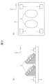
- FIG. 2(a) is a side view showing the state of the sample 1 and the product 2 after lamination molding is completed.
- FIG. 2(b) is a top view of the state shown in FIG. 2(a).
- the sample 1 arranged at a position that does not come into contact with the product 2 is also molded at the same time as the product 2. Furthermore, the arrangement of the sample 1 is preferably such that only the sample 1 can be separated from the base plate 3 without separating the product 2 from the base plate 3 .
- the sample 1 is arranged at the four corners of the base plate, so that only the sample 1 can be separated from the base plate 3 without separating the product 2 from the base plate 3.
- FIG. 2B is just an example, and the number of samples 1 laminated and manufactured simultaneously with the product 2 is not limited to four.
- Laminated manufacturing of sample 1 and product 2 was performed using a modeling apparatus that first solidified the molten modeling material on the base plate 3, and then solidified the molten modeling material on the solidified modeling material.
- a modeling apparatus includes, for example, a powder-in-bed type layered modeling apparatus, which is a technique well known to those skilled in the art, and thus description thereof will be omitted.
- the base plate 3 is arranged substantially parallel to the xy plane (eg, horizontal plane). As the layered manufacturing progresses, the sample 1 and the product 2 start from the upper surface of the base plate 3 and are piled up one by one along the +z-axis direction (upward direction).
- a dimensional quality evaluation method and an evaluation system for evaluating the dimensional quality of the product 2 laminated and manufactured by the powder bed type laminated manufacturing apparatus will be described as an example. It is also widely applicable to products (laminate-molded bodies) that are laminate-molded by the laminate-molding apparatus.
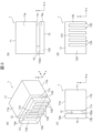
- FIG. 3(a) is a perspective view showing the shape of the sample 1 shown in FIGS. 2(a) and 2(b).
- FIG. 3(b) is a top view of the sample 1 shown in FIG. 3(a).
- FIG. 3(c) is a side view of the sample 1 shown in FIG. 3(a).
- FIG. 3(d) is a side view of the sample 1 viewed from a direction different from that of FIG. 3(c).
- the sample 1 has a reference portion 11 serving as a reference for measuring the dimensions of the sample 1, a deformation portion 13 connected to the reference portion 11, and a connection portion 12 connecting the reference portion 11 and the deformation portion 13.
- the reference part 11 forms a block body with a flat surface (that is, without undulations or irregularities on the surface).
- the reference portion 11 is a hexahedron such as a rectangular parallelepiped.
- the upper surface 11 a of the reference portion 11 is layered and manufactured substantially parallel to the base plate 3 .
- a side surface 11 c of the reference portion 11 is laminated and manufactured substantially perpendicularly to the base plate 3 .
- a bottom surface 11b of the reference portion 11 is layered and molded in contact with the base plate 3 .
- the deformation portion 13 is arranged on the side of the reference portion 11 .
- the upper surface 13 a of the deformable portion 13 is layered and manufactured to have substantially the same height as the upper surface 11 a of the reference portion 11 .
- the upper surface 13a of the deformation portion 13 is arranged so that the height from the base plate 3 (or the bottom surface 13b) is substantially the same as the height of the upper surface 11a of the reference portion 11 from the base plate 3 (or the bottom surface 11b).
- the upper surface 13a of the deformable portion 13 is laminate-molded to have a smaller area than the upper surface 11a of the reference portion 11 .
- the deformation portion 13 shown in FIGS. 3(a) to 3(d) has a beam portion 131, a column portion 132, and a support portion 133.
- the pillars 132 extend upward from the base plate 3 .
- the beam portion 131 protrudes from the tip portion of the column portion 132 along the base plate 3 and extends substantially parallel to the base plate 3 .
- the support portion 133 extends downward from the beam portion 131 to the base plate 3 and supports the beam portion 131 .
- the support portion 133 has a gap 134 that communicates the beam portion 131 and the base plate 3 .
- a side surface 132 a of the column portion 132 is connected to a side surface 11 c of the reference portion 11 by the connecting portion 12 .
- the deformed portion 13 shown in FIGS. 3(a) to 3(d) is similar to the comb-tooth test piece C for comparison with the cantilever sample C, which is conventionally known in the field of additive manufacturing. It has a support portion 133 with a rounded shape.
- the support portion 133 has a structure in which a plurality of plate-like members 135 extending in the vertical direction (z-axis direction) are arranged apart from each other in the direction along the base plate 3 .
- a gap 134 is formed between the plurality of plate-like members 135 .
- the deformed portion 13 resembles a shape known as a comb test piece C.
- FIG. the shape of the sample 1 in which the deformation portion 13 is connected to the reference portion 11 by the connection portion 12 and integrated is not known.
- the dimensional quality evaluation method of the present embodiment can be used even if the sample 1 and the product 2 are laminated and manufactured at the same time on the same base plate 3. 1 can be measured easily and accurately.
- the effect of using the sample 1 in comparison with the conventional comb tooth test piece C will be explained.
- the modeled objects such as the product 2 and the sample 1 are heated and cooled.
- thermal stress occurs due to the repetition of Specifically, the top surface of the object to which the molding material melted by lamination is added becomes hot, and thermal energy is transferred from the high temperature top surface to the relatively low temperature base plate 3 by thermal conduction, and the top surface becomes hot. Cooled. The thermal expansion and contraction of the modeled object due to this heating and cooling are repeated each time lamination is performed, thereby generating thermal stress.
- the magnitude of the thermal stress increases as the temperature history in the modeled article becomes uneven, and the direction of the thermal stress is the direction in which the upper part of the modeled article contracts and the lower part expands.
- the resulting object is warped upward, so the object basically undergoes warping deformation.
- the amount of deformation is limited to a small range, and thermal stress acts as residual stress on the object. remain within.
- the modeled object is deformed so as to warp up relatively largely due to the residual stress.
- the deformation amount of the sample 1 is the amount of deformation of the sample 1 when the sample 1 is deformed so as to warp when the sample 1 is separated from the base plate 3 after lamination molding. That is, the amount of deformation of the sample 1 is the amount of deformation of the sample 1 before and after the layered and manufactured sample 1 is separated from the base plate 3 .
- the amount of deformation of the product 2 is the amount of deformation of the product 2 when the laminate-molded product 2 is separated from the base plate 3 so that the product 2 is warped and deformed. That is, the amount of deformation of the product 2 is the amount of deformation of the product 2 before and after the layered and manufactured product 2 is separated from the base plate 3 .
- the amount of deformation of sample 1 or product 2 can also be interpreted as the amount of dimensional change from the designed shape of sample 1 or product 2 .
- the comb tooth test piece C shown in FIG. 4 is a test piece for measuring the amount of deformation by utilizing the characteristics of thermal deformation in the above-described layered manufacturing.
- a beam portion C1 extending substantially parallel to the xy plane is connected to the base plate 3 by a column portion C2 extending along the z-axis and a comb-like support portion C3. Since the support portion C3 has the gap C4, the heat transfer coefficient between the beam portion C1 and the base plate 3 changes depending on the position inside the beam portion C1. As a result, the non-uniformity of the temperature history (hysteresis) inside the beam portion C1 increases, and the thermal stress generated in the beam portion C1 increases.
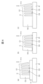
- FIG. 4(a) is a side view showing how the base plate 3 is placed on the measurement stage 41 before the comb test piece C is cut off.
- FIG. 4(b) is a side view showing how the comb tooth test piece C separated from the base plate 3 is placed on the measurement stage 41.
- FIG. 4(c) is a side view showing how a comb tooth test piece C having a shape different from that of FIG. 4(b) is placed on the measurement stage 41.
- the base plate 3 to which the comb tooth test piece C is connected is placed on the measurement stage 41 for measuring the amount of deformation.
- a base plate 3 that is flat and has a uniform thickness, it is possible to accurately measure the amount of warp-up deformation of the beam portion C1 on the upper portion of the comb tooth test piece C.
- FIG. The base plate 3 can also be deformed by layered manufacturing, but the amount of deformation of the base plate 3 is sufficiently small compared to the amount of deformation of the comb-teeth test piece C, so it can be substantially ignored.
- FIG. 4(b) a comb tooth test piece C separated from the base plate 3 is placed on the measurement stage 41.
- the bottom surface of the column portion C2 and the bottom surface of the support portion C3 cannot exist on the same plane.
- FIG. 4B only a portion of the bottom surface of the pillar portion C2 and a portion of the bottom surface of the support portion C3 are in contact with the measurement stage 41.
- the comb test piece C rotates in the zx plane, and it is difficult to accurately measure the warping deformation amount of the beam C1 on the top of the comb test piece C.
- FIG. 4(c) on the measurement stage 41 is placed a comb tooth test piece C in which the volume ratio of the columnar portion C2 to the support portion C3 is greater than in the case of FIG. 4(b).
- the comb test piece C shown in FIG. 4(c) can be prevented from rotating in the zx plane that occurs in the case of FIG. 4(b).
- the bottom surface of the pillar C2 separated from the base plate 3 is not parallel to the xy plane (that is, not parallel to the base plate 3)
- the bottom surface of the pillar C2 is not parallel to the xy plane with respect to the measurement stage 41. tilt.
- the beam C1 above the comb-teeth test piece C placed on the measurement stage 41 also inclines, making it difficult to accurately measure the amount of warp-up deformation of the beam C1.
- the deformation amount of the beam portion 131 that warps upward can be measured with accuracy as described below. It is possible to measure well.
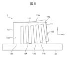
- FIG. 5 is a side view showing how the sample 1 separated from the base plate 3 is placed on the measurement stage 41.
- the deformed portion 13 of the sample 1 is deformed such that the beam portion 131 on the upper portion of the deformed portion 13 warps up, similarly to the comb test piece C shown in FIGS. 4(a) to 4(c).
- the deformed portion 13 can ignore rotation in the zx plane even when completely separated from the base plate 3. be. This is because the deformation portion 13 is connected to the reference portion 11 by the connection portion 12 .
- the area of the bottom surface 11b in contact with the base plate 3 is larger than the area of the bottom surface 13b of the deformation portion 13.
- the deformation portion 13 is arranged on the side of the reference portion 11 and connected to the reference portion 11 via the connection portion 12 . Therefore, the sample 1 can be placed on the measurement stage 41 without overturning.
- the reference portion 11 Since the reference portion 11 forms a block with a flat surface, the amount of deformation of the reference portion 11 can be ignored compared to the amount of deformation of the deformation portion 13 . This is for the following two reasons. First, the heat transfer coefficient between the reference portion 11 and the base plate 3 is substantially constant regardless of the internal position of the reference portion 11 . This is because the temperature history becomes substantially uniform inside the reference portion 11 and the thermal stress generated in the reference portion 11 is reduced. Second, the thickness of the reference portion 11 in the z-axis direction (vertical direction) is thicker than the thickness of the beam portion 131 in the z-axis direction. This is because the reference portion 11 is mechanically less deformable than the beam portion 131 (high in rigidity).
- the sample 1 placed on the measurement stage 41 is tilted.
- the area of the upper surface 11a of the reference portion 11 is larger than the area of the upper surface 13a of the deformation portion 13 (beam portion 131), a large number of measurement points for measuring the height of the upper surface 11a can be provided on the upper surface 11a. .
- the height of the upper surface 11a of the reference portion 11 is measured at a large number of measurement points, so that the measurement accuracy is improved.
- the dimensional quality evaluation method of the present embodiment can precisely measure the deformation amount of the sample 1 after laminating and manufacturing the sample 1 and the product 2 at the same time by separating the sample 1 from the base plate 3 .
- the dimensional quality evaluation method of this embodiment does not require cutting the base plate 3 itself, unlike the conventional method using the comb tooth test piece C. No hassle and no cost. Therefore, according to the dimensional quality evaluation method of the present embodiment, the sample 1 can be formed simultaneously with the product 2, and the deformation amount of the sample 1 can be accurately measured. can be evaluated well.
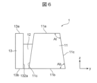
- FIG. 6 is a diagram explaining a modified example of the reference portion 11.
- the reference portion 11 has an angle At of 90 degrees or more formed between the upper surface 11a and the side surface 11c of the reference portion 11 in the cross section, and the angle formed between the bottom surface 11b and the side surface 11c of the reference portion 11 in the cross section.
- Ab may be 90 degrees or less.
- the cross-sectional area of the heat conduction path from the stacked top surface to the base plate 3, that is, the xy cross-sectional area of the already-molded portion existing under the top surface, is can be greater than or equal to the cross-sectional area of the top surface. With such a heat conduction path, the reference portion 11 can prevent the temperature of the uppermost surface from becoming abnormally high as a whole or locally.
- the abnormally high temperature of the uppermost surface degrades the flatness of the upper surface 11a of the reference portion 11 after cooling. Therefore, when the angle At is 90 degrees or more and the angle Ab is 90 degrees or less, the flatness of the upper surface 11a of the reference portion 11 is improved, and the deformation amount of the sample 1 can be measured with high accuracy. becomes possible. That is, it is preferable that the cross section of the reference portion 11 is trapezoidal or rectangular.
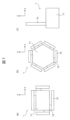
- FIG. 7 is a diagram illustrating a modification of sample 1.
- FIG. 7A is a diagram illustrating a modification of sample 1.
- FIG. 7(b) is a diagram illustrating a modified example of sample 1 that is different from FIG. 7(a).
- FIG. 7(c) is a diagram illustrating a modified example of the sample 1 that is different from FIGS. 7(a) and 7(b).
- a plurality of deformation portions 13 may be connected to one reference portion 11.
- the reference portion 11 of the sample 1 may be a block such as a hexagonal prism instead of a hexahedron.
- the sample 1 may have a shape in which the deformation portion 13 protrudes from the reference portion 11, as shown in FIG. 7(c).
- the column portion 132 of the deformation portion 13 may be provided separately from the reference portion 11 .
- the reference portion 11 may also serve as the column portion 132 and the beam portion 131 may extend from the reference portion 11 .
- the difference between the sample 1 shown in FIG. 7C and the comb test piece C shown in FIG. 4C is that the sample 1 shown in FIG.
- the width of the reference portion 11 along the direction (the length in the x-axis direction in FIG. 7C) is sufficiently larger than the width of the beam portion 131 .
- the width of the columnar portion C2 (the length in the y-axis direction in FIG. 4(c)) is substantially the same as the width of the beam portion C1.
- the width of the reference portion 11 is larger than the width of the beam portion 131, the area of the upper surface 11a of the reference portion 11 in the sample 1 shown in FIG. It can be larger than area.
- the sample 1 shown in FIG. It is possible to estimate the measurement error of the height of the upper surface 13a of the beam portion 131 and correct the amount of warping deformation of the beam portion 131 .
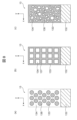
- FIG. 8 is a diagram illustrating a modification of the deformation section 13. As shown in FIG. FIG. 8A is a diagram illustrating a modification of the support portion 133 of the deformation portion 13.
- FIG. 8B is a diagram illustrating a modified example of the support portion 133 different from FIG. 8A.
- FIG. 8(c) is a diagram illustrating a modified example of the support portion 133 different from FIGS. 8(a) and 8(b). 8(a) to 8(c) show cross-sectional views of the deformation portion 13 taken along the xy plane passing through the column portion 132 and the support portion 133.
- FIG. 8A is a diagram illustrating a modification of the support portion 133 of the deformation portion 13.
- FIG. 8B is a diagram illustrating a modified example of the support portion 133 different from FIG. 8A.
- FIG. 8(c) is a diagram illustrating a modified example of the support portion 133 different from FIGS. 8(a) and 8(b).
- the support portion 133 shown in FIGS. 3(a) to 3(d) has a structure in which a plurality of vertically extending plate-like members 135 are arranged apart from each other in the direction along the base plate 3. As shown in FIG. However, the support portion 133 of this embodiment only needs to extend downward from the beam portion 131 to the base plate 3 to support the beam portion 131 and have a gap 134 that communicates the beam portion 131 and the base plate 3 . Since the support portion 133 has the gap 134 , the heat transfer coefficient between the beam portion 131 and the base plate 3 changes depending on the position inside the beam portion 131 .
- the support portion 133 includes a plurality of vertically extending rod-shaped members 136 arranged apart from each other, and gaps 134 are formed between the plurality of rod-shaped members 136. You may have a structure.
- the support portion 133 may have a structure constituted by a mesh-like member 137 having a void 134 inside.
- the support portion 133 may have a structure constituted by a porous member 138 having a void 134 therein.
- step S ⁇ b>2 of separating the laminate-manufactured sample 1 from the base plate 3 the laminate-manufactured sample 1 is cut from the base plate 3 after the laminate-manufacturing of the sample 1 and the product 2 is completed.
- a method for separating the sample 1 from the base plate 3 various methods such as wire electric discharge machining or laser cutting can be used.
- FIG. 9 shows a measuring device 4 for measuring the amount of deformation of the sample 1. As shown in FIG.
- step S3 of measuring the deformation amount of the sample the dimensions of the sample 1 separated from the base plate 3 are measured to measure the deformation amount of the sample 1.
- Measuring the amount of deformation of the sample 1 in step S3 means measuring the difference value between the dimension of the reference portion 11 and the dimension of the deformed portion 13 in the separated sample 1 .
- measuring the amount of deformation of the sample 1 means measuring the difference between the height of the upper surface 11a of the reference portion 11 and the height of the upper surface 13a of the deformed portion 13 in the separated sample 1. It is to be.
- the laser displacement sensor 43 supported by the sensor support portion 42 is arranged above the sample 1 placed on the measuring stage 41 .
- the laser displacement sensor 43 irradiates a laser beam 44 toward the sample 1 arranged below the laser displacement sensor 43 , receives the laser beam 44 reflected by the sample 1 , and detects the laser beam of the sample 1 .
- the height of the measurement point irradiated with the light 44 is measured.
- the laser displacement sensor 43 is movable in the y-axis direction, and the measurement stage 41 is movable in the x-axis direction.
- the laser displacement sensor 43 can easily measure relative heights from the reference plane at a plurality of measurement points on the upper surface 11 a of the reference portion 11 and the upper surface 13 a of the deformation portion 13 . Determining the heights of the upper surface 11a of the reference portion 11 and the upper surface 13a of the deformation portion 13 from the measurement signals can be easily performed by well-known signal processing and data processing techniques.
- This data processing technique includes a technique of calculating the inclination of the sample 1 from the height measurement data of the upper surface 11 a of the reference portion 11 . Further, this data processing technique includes a technique for calculating a height fluctuation value ze generated at a measurement point on the upper surface 13a of the deformation portion 13 from the calculated inclination.
- this data processing technique subtracts the calculated variation value ze from the measurement data z′ of the height of the measuring point of the deforming portion 13 (z′ ⁇ ze), height measurements and correction techniques.
- the measuring device 4 using the laser displacement sensor 43 is illustrated in FIG. 9 , the measuring device 4 may be a measuring device using a method other than the laser displacement sensor 43 .
- step S3 the height of the upper surface 11a of the reference portion 11 and the height of the upper surface 13a of the deformed portion 13 in the separated sample 1 are measured. Then, in step S ⁇ b>3 , the measured value of the height of the upper surface 11 a of the reference portion 11 is subtracted from the measured value of the height of the upper surface 13 a of the deformed portion 13 . As a result, in step S3, the difference value between the height of the upper surface 11a of the reference portion 11 and the height of the upper surface 13a of the deformation portion 13 can be obtained.
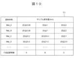
- FIG. 10 is a diagram showing a dimensional quality determination table T1 according to the first embodiment.
- step S4 the dimensional quality of the additive manufacturing batch containing the sample 1 is evaluated based on the measured deformation amount of the sample 1.
- step S4 evaluates the dimensional quality of the product 2 contained in the additive manufacturing batch by evaluating the dimensional quality of the additive manufacturing batch containing the sample 1.
- step S4 uses the dimensional quality determination table T1 shown in FIG. 10 to evaluate the dimensional quality of the product 2 included in the layered manufacturing batch by determining the dimensional quality grade of the layered manufacturing batch. do.
- the dimensional quality determination table T1 defines the correspondence between the type of modeling material used in the layered manufacturing batch, the deformation amount of the sample 1 included in the layered manufacturing batch, and the dimensional quality grade of the layered manufacturing batch. It is a table. For example, in a layered manufacturing batch in which the modeling material A is used, it is assumed that the amount of deformation of the sample 1 included in the batch is 0.3 mm.
- the dimensional quality grade of the laminate manufacturing batch is determined to be B, and the dimensional quality grade of product 2 is B. Determine that there is.
- the amount of deformation of the sample 1, which is used as a criterion for determining the grade of dimensional quality may be a value determined in advance by the user.
- the amount of deformation of the sample 1, which is the criterion for the grade of dimensional quality can be determined by a person or a computer based on the amounts of deformation of a plurality of samples 1.
- step S4 the dimensional quality of the layered manufacturing batch (that is, the product 2) may be evaluated without using the dimensional quality determination table T1.
- step S4 may assess the dimensional quality by scoring against the measured deformation of the sample 1 rather than the dimensional quality grade.
- the dimensional quality evaluation method of the present embodiment can evaluate the dimensional quality of the product 2 by evaluating the dimensional quality of the additive manufacturing batch containing the sample 1 based on the deformation amount of the sample 1.
- To evaluate the dimensional quality of the product 2 it is desirable to consider the influence of the design shape of the product 2 on the dimensional quality and the influence of factors other than the design shape of the product 2 on the dimensional quality.
- the impact of the design shape of product 2 on dimensional quality is relatively straightforward. For example, the amount of deformation of the elongated product 2 is likely to be greater than that of the thick and short product 2, so the dimensional quality of the elongated product 2 is lower than the dimensional quality of the thick and short product 2. easy.
- Factors other than the design shape of the product 2 that affect the dimensional quality include differences in modeling conditions, modeling devices, and modeling materials. Differences in modeling conditions are, for example, differences in various parameters set in the modeling apparatus. Differences between modeling apparatuses include individual differences among modeling apparatuses as well as differences due to changes over time in one modeling apparatus. Differences in building materials include differences in the shape of materials as well as differences in chemical components of materials. The difference in the shape of the material, for example, in the case of a powdery material, is the difference in powder size and sphericity (degree of approximation to a true sphere). The difference in the shape of the material is also the thickness of the filaments, for example, in the case of filamentary materials.
- the dimensional quality of the product 2 is influenced by a combination of factors related to the design shape of the product 2 and factors other than the design shape. In practice, however, factors other than the design shape of the product 2 that affect dimensional quality are generally complex and difficult to predict.
- the dimensional quality evaluation method of the present embodiment evaluates the dimensional quality of the laminate manufacturing batch containing the sample 1 based on the deformation amount of the sample 1, so that even if it is a relatively simple method, the product 2
- the dimensional quality of the product 2 can be evaluated by considering the influence of factors other than the design shape of the product 2 on the dimensional quality. Therefore, the dimensional quality evaluation method of the present embodiment can easily and accurately evaluate the dimensional quality of the laminate-molded body.
- the evaluation result of the dimensional quality of this embodiment can be used, for example, when laminate manufacturing is performed on the product 2 of similar design and the dimensional quality is evaluated. That is, it is possible to first evaluate the dimensional quality of both the product 2 and the sample 1, and then evaluate the dimensional quality of the product 2 according to the evaluation result of the dimensional quality of the sample 1.
- the evaluation result of the dimensional quality of the present embodiment can be used for monitoring and improving the condition of the modeling conditions, the modeling apparatus, the modeling material, or the like. A closer look at these factors allows for easier condition monitoring and improvement.
- the evaluation result of the dimensional quality of the present embodiment shows that when the designer and the modeler of the product 2 are different and the dimensional quality of the product 2 is insufficient, the cause is investigated, and the responsibility and It can be used to clarify the location of countermeasures.
- the dimensional quality evaluation method of the present embodiment is a method of evaluating the dimensional quality of the product 2 laminated and manufactured on the base plate 3 .
- the dimensional quality evaluation method is to laminate-manufacture the sample 1 for evaluating the dimensional quality of the product 2 at the same time as the product 2 (that is, in the same lamination-manufacturing batch) on the base plate 3 on which the product 2 is laminated-manufactured (process S1).
- the dimensional quality evaluation method includes separating the laminate-manufactured sample 1 from the base plate 3 (step S2).
- the dimensional quality evaluation method includes measuring the deformation amount of the sample 1 before and after being cut off from the base plate 3 by measuring the dimensions of the cut sample 1 (step S3).
- the dimensional quality evaluation method includes evaluating the dimensional quality of the product 2 based on the measured deformation amount of the sample 1 (step S4).
- the sample 1 has a reference portion 11 and a deformation portion 13 connected to the reference portion 11 via a connection portion 12 .
- the amount of deformation of the sample 1 is the difference between the dimensions of the reference portion 11 and the deformed portion 13 of the separated sample 1 .
- the dimensional quality evaluation method of the present embodiment can accurately measure the deformation amount of the sample 1 without cutting the base plate 3 itself, unlike the conventional method using the comb tooth test piece C. .
- a complicated step of cutting the base plate 3 is not required, and the base plate 3 need not be discarded. It becomes possible to use the base plate 3 again for layered manufacturing, and continuous use of the molding apparatus becomes possible.
- the dimensional quality evaluation method of the present embodiment can evaluate the dimensional quality of the product 2 in consideration of the influence of various factors such as molding conditions on the dimensional quality. Therefore, the dimensional quality evaluation method of the present embodiment can easily and accurately evaluate the dimensional quality of the laminate-molded body.
- the reference portion 11 forms a block with a flat surface
- the deformation portion 13 is arranged on the side of the reference portion 11 .
- the upper surface 11 a of the reference portion 11 is layered and manufactured substantially parallel to the base plate 3 .
- the upper surface 13 a of the deformable portion 13 is laminate-molded to have substantially the same height as the upper surface 11 a of the reference portion 11 and has a smaller area than the upper surface 11 a of the reference portion 11 .
- the deformation amount of the sample 1 is the difference value between the height of the upper surface 11 a of the reference portion 11 and the height of the upper surface 13 a of the deformed portion 13 in the separated sample 1 .
- the dimensional quality evaluation method of the present embodiment calculates the inclination of the sample 1 from the measurement data of the height of the upper surface 11a of the reference portion 11 even when the bottom surface 11b of the reference portion 11 is not parallel to the xy plane.
- the dimensional quality evaluation method of this embodiment can accurately measure the deformation amount of the sample 1 using a relatively simple existing measuring device as shown in FIG. Therefore, the dimensional quality evaluation method of the present embodiment can more easily and accurately evaluate the dimensional quality of the laminate-molded body.
- the angle At formed by the upper surface 11a and the side surface 11c of the reference portion 11 in the cross section of the reference portion 11 is 90 degrees or more, and the reference portion 11 The angle Ab formed by the bottom surface 11b and the side surface 11c of is 90 degrees or less.
- the heat conduction path from the stacked uppermost surface to the base plate 3 can be larger than the cross-sectional area of the uppermost surface during lamination-molding of the reference portion 11 . Therefore, the dimensional quality evaluation method of the present embodiment can maintain good flatness of the upper surface 11a of the reference portion 11 after lamination manufacturing, so that the deformation amount of the sample 1 can be measured with high accuracy. Therefore, the dimensional quality evaluation method of the present embodiment can easily and accurately evaluate the dimensional quality of the laminate-molded body.
- the deformed portion 13 that has been laminated and manufactured includes a column portion 132 extending upward from the base plate 3, a beam portion 131 extending from the column portion 132 along the base plate 3, and a beam portion 131 and a support portion 133 extending downward from the base plate 3 to support the beam portion 131 .
- the support portion 133 has a gap 134 that communicates the beam portion 131 and the base plate 3 .
- a side surface 132 a of the column portion 132 is connected to a side surface 11 c of the reference portion 11 .
- the dimensional quality evaluation method of the present embodiment can make the shape of the deformed portion 13 similar to the conventional comb-tooth test piece C. Therefore, the dimensional quality evaluation method of the present embodiment utilizes knowledge such as modeling data and analysis results of simulation analysis used to evaluate the dimensional quality of the product 2 using the conventional comb test piece C. , the dimensional quality of the product 2 can be evaluated. Therefore, the dimensional quality evaluation method of the present embodiment can more easily and accurately evaluate the dimensional quality of the laminate-molded body.
- FIG. 11 is a diagram showing the configuration of the dimensional quality evaluation system 5 of the first embodiment.
- the dimensional quality evaluation system 5 of this embodiment is a system that evaluates the dimensional quality of the product 2 laminated and manufactured on the base plate 3 .
- the dimensional quality evaluation system 5 includes one or a plurality of terminal devices 51, an arithmetic processing device 52, and a storage device 53, which are interconnected via a communication network 50 so as to be able to communicate with each other.
- the communication network 50 is a wired or wireless communication network capable of transmitting and receiving digital data.
- the communication network 50 may include, for example, a data transmission path (bus) within one computer, the Internet network, a carrier network, or the like.
- the terminal device 51 is an electronic device having an input function, an output function and a communication function.
- the arithmetic processing unit 52 is a computer having a CPU.
- the storage device 53 is a computer with a storage device such as a hard disk drive or solid state drive.
- One terminal device 51 and arithmetic processing device 52 may be included in one computer.
- the arithmetic processing device 52 and the storage device 53 may be included in one computer.
- the user of the dimensional quality evaluation system 5 sends the user information, the type of modeling material used for lamination modeling of the product 2 and the sample 1 in the above step S1, and the deformation amount of the sample 1 measured in the above step S3 to the terminal device. 51 to access the arithmetic processing unit 52 from the terminal device 51 . That is, the terminal device 51 acquires the amount of deformation of the sample 1 before and after the sample 1, which has been laminate-molded at the same time as the product 2 on the base plate 3 on which the product 2 is laminate-molded, is separated from the base plate 3 . Then, the terminal device 51 transmits the user information, the type of modeling material, and the deformation amount of the sample 1 to the arithmetic processing device 52 .
- the arithmetic processing unit 52 stores the type of modeling material and the amount of deformation of the sample 1 transmitted from the terminal device 51 in the storage area of the storage device 53 assigned for each user information.
- the storage device 53 stores in advance a dimensional quality determination table T1 that defines the correspondence between the type of modeling material, the amount of deformation of the sample 1, and the grade of dimensional quality.
- the arithmetic processing unit 52 reads the dimensional quality determination table T1 from the storage device 53 .
- the arithmetic processing unit 52 determines the dimensional quality grade corresponding to the type of modeling material and the amount of deformation of the sample 1 transmitted from the terminal device 51 using the dimensional quality determination table T1.
- the arithmetic processing unit 52 evaluates the dimensional quality of the layered manufacturing batch layeredly manufactured in the above step S1. That is, the processor 52 evaluates the dimensional quality of the product 2 based on the amount of deformation of the sample 1 transmitted from the terminal device 51 . Then, the arithmetic processing unit 52 transmits the evaluation result of the dimensional quality to the terminal device 51 .
- the terminal device 51 displays the evaluation result transmitted from the arithmetic processing device 52 . Thus, the user can confirm the evaluation results displayed on the terminal device 51 .
- the user can also request the arithmetic processing device 52 to compare and display a plurality of data relating to the deformation amount of the sample 1 from the terminal device 51 .
- the arithmetic processing unit 52 to which this request has been sent reads data that can be disclosed to the user from the storage device 53 and transmits the data to the terminal device 51 in a predetermined format. Then, the terminal device 51 displays the result of comparing a plurality of data relating to the deformation amount of the sample 1 transmitted from the arithmetic processing device 52 .
- the user can confirm the tendency of the amount of deformation of the sample 1 by confirming the comparison result displayed on the terminal device 51 .
- FIG. 12 is a diagram showing an example of a screen 510 displayed on the terminal device 51 shown in FIG.
- a screen 510 shown in FIG. 12 is a web application screen for input/output and operation using a web browser on the terminal device 51 . Specifically, screen 510 shown in FIG. 12 is displayed after connecting to a predetermined web address and logging in using pre-registered user information.
- a screen 510 shown in FIG. 12 includes an input field 5101 for the type of modeling material, an input field 5102 for the amount of deformation of sample 1, an evaluation execution button 5103, and a display field 5104 for the evaluation result of dimensional quality. Further, the screen 510 includes a data display column 5105 for comparing and displaying a plurality of data relating to the deformation amount of the sample 1 saved in the storage device 53, and a filter 5106 for selecting data to be displayed in the data display column 5105. including.
- the display format of the graph in the data display column 5105 is the format of a scattering plot, but other formats such as a line chart, bar graph, or frequency distribution chart may be used. may be a combination of
- the display format of the data in the data display column 5105 is graph format, but may be table format or both graph and table formats.
- the display format of the data in the data display field 5105 may be switched by the user's operation.
- the evaluation execution button 5103 when the evaluation execution button 5103 is operated by the user, information is displayed in both the dimensional quality evaluation result display field 5104 and the data display field 5105 at the same time. It may be configured to be divided and display information separately on both.
- the dimensional quality evaluation system 5 of this embodiment is a system that evaluates the dimensional quality of the product 2 laminated and manufactured on the base plate 3 .
- the dimensional quality evaluation system 5 determines the amount of deformation of the sample 1 before and after separating the sample 1 that has been laminate-manufactured at the same time as the product 2 (that is, in the same laminate-manufacturing batch) on the base plate 3 on which the product 2 is laminate-manufactured.
- the dimensional quality evaluation system 5 includes an arithmetic processing unit 52 that is communicably connected to the terminal device 51 and that evaluates the dimensional quality of the product 2 based on the deformation amount of the sample 1 transmitted from the terminal device 51 .
- the sample 1 has a reference portion 11 and a deformation portion 13 connected to the reference portion 11 .
- the amount of deformation of the sample 1 is the difference between the dimensions of the reference portion 11 and the deformed portion 13 of the separated sample 1 .
- the dimensional quality evaluation system 5 of the present embodiment is different from the conventional method using the comb-teeth test piece C, and is based on the deformation amount of the sample 1 that is accurately measured without cutting the base plate 3 itself. , the dimensional quality of the product 2 can be evaluated. A complicated step of cutting the base plate 3 is not required, and the base plate 3 need not be discarded. It becomes possible to use the base plate 3 again for layered manufacturing, and continuous use of the molding apparatus becomes possible.
- the dimensional quality evaluation system 5 of the present embodiment can evaluate the dimensional quality of the product 2 in consideration of the influence of various factors such as molding conditions on the dimensional quality. Therefore, the dimensional quality evaluation system 5 of the present embodiment can easily and accurately evaluate the dimensional quality of the laminate-molded body.
- the dimensional quality evaluation system 5 of this embodiment further includes a storage device 53 communicably connected to the arithmetic processing device 52 .
- the terminal device 51 further acquires the types of modeling materials used for the layered modeling of the product 2 and the sample 1 .
- the storage device 53 stores in advance a dimensional quality determination table T1 that defines the correspondence between the type of modeling material, the amount of deformation of the sample 1, and the grade of dimensional quality.
- the arithmetic processing unit 52 determines the dimensional quality of the product 2 by using the dimensional quality determination table T1 to determine the dimensional quality grade corresponding to the type of modeling material and the amount of deformation of the sample 1 transmitted from the terminal device 51. Evaluate.
- the arithmetic processing unit 52 of this embodiment can accurately evaluate the dimensional quality of the product 2 without using a complicated evaluation algorithm. Therefore, the dimensional quality evaluation system 5 of the present embodiment can more easily and accurately evaluate the dimensional quality of the laminate-molded body.
- FIG. 2 A dimensional quality evaluation method and evaluation system for a layered product according to the second embodiment will be described with reference to FIGS. 13 to 18.
- FIG. 1 In the dimensional quality evaluation method and the evaluation system thereof according to the second embodiment, descriptions of the same configurations and operations as those of the first embodiment will be omitted.
- FIG. 13 is a diagram showing the overall process of the dimensional quality evaluation method of the second embodiment.
- the dimensional quality evaluation method of the second embodiment includes steps S1 to S3 similar to those of the first embodiment. Furthermore, the dimensional quality evaluation method of the second embodiment includes step S5 of selecting a correlation model for predicting the correlation between the deformation amount of the product 2 and the deformation amount of the sample 1, and and step S6 of evaluating dimensional quality. Step S5 is a step that is not included in the dimensional quality evaluation method of the first embodiment. Step S6 is a step different in content from step S4 of the first embodiment.
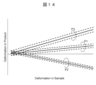
- FIG. 14 is a diagram showing an example of a correlation model.
- a correlation model is selected that predicts the correlation between the deformation amount of the product 2 whose dimensional quality is to be evaluated and the deformation amount of the sample 1 that was laminated and manufactured at the same time as the product 2.
- the correlation model is not a model that predicts the correlation between the amount of deformation of Product 2 and the amount of deformation of Sample 1, but a model that predicts the correlation between the index related to the dimensional quality of Product 2 and the amount of deformation of Sample 1.
- indices related to the dimensional quality of the product 2 include the dimensions of the product 2, the dimensional error of the product 2, the grade of the dimensional quality of the product 2, and the like.
- the horizontal axis of FIG. 14 indicates the amount of deformation of sample 1, and the vertical axis of FIG. 14 indicates the predicted value of the amount of deformation of product 2.
- Symbol P1 in FIG. 14 indicates a correlation model that predicts the correlation between the amount of deformation of the product P1 and the amount of deformation of the sample 1 that was layered and manufactured at the same time as the product P1.
- Symbol P2 in FIG. 14 indicates a correlation model that predicts the correlation between the amount of deformation of the product P2 and the amount of deformation of the sample 1 that was layered and manufactured at the same time as the product P2.
- Symbol P3 in FIG. 14 indicates a correlation model that predicts the correlation between the amount of deformation of the product P3 and the amount of deformation of the sample 1 that was layered and manufactured at the same time as the product P3.
- the solid line in FIG. 14 indicates the predicted value of the deformation amount of the product 2 corresponding to the deformation amount of the sample 1.
- the dashed line in FIG. 14 indicates the error range of the predicted deformation amount of the product 2 .
- the error range of the predicted deformation amount of the product 2 is, for example, twice the standard deviation ⁇ .
- the error range of 2 ⁇ is a range in which the true value is included with a probability of 95% when it is assumed that the error has a normal distribution.
- step S5 a correlation model associated with the type of product 2 closest to the product 2 whose dimensional quality is to be evaluated is selected.
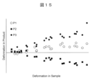
- FIG. 15 is a diagram explaining a method of constructing the correlation model shown in FIG.
- One method of constructing a correlation model is a method of constructing by regression analysis of the measured values of each deformation amount of product 2 and sample 1. For example, by selecting one or a plurality of products 2 that are molded at the same time as sample 1, measuring the amount of deformation of sample 1, and also measuring the amount of deformation of product 2, and performing regression analysis on the measured values of each amount of deformation. , a correlation model can be constructed.
- the horizontal axis of FIG. 15 indicates the measured deformation amount of sample 1
- the vertical axis of FIG. 15 indicates the measured deformation amount of products P1 to P3. If the modeling material is the same, the sample 1 and a plurality of types of products 2 may be modeled at the same time, and each deformation amount may be measured. As a result, it is possible to collect the data necessary for constructing the correlation model with a relatively small number of man-hours.
- Types of regression analysis used to build correlation models include, for example, least squares method, Lasso regression method, ridge regression method, kernel ridge regression method, support vector regression method, or neural network regression.
- Another method for constructing a correlation model is to construct a regression analysis of the results of a thermal deformation simulation of additive manufacturing. For example, a thermal deformation simulation is performed using a simulation model that reproduces the shapes of sample 1 and product 2, each deformation amount of sample 1 and product 2 is obtained from the results, and the obtained deformation amount is subjected to regression analysis. By doing so, a correlation model can be constructed. Furthermore, it is also possible to construct a correlation model by combining both the measured deformation amounts of the product 2 and the sample 1 and the simulation results.
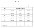
- FIG. 16 is a diagram showing a dimensional quality determination table T2 according to the second embodiment.
- step S6 the measured deformation amount of the sample 1 is input to the selected correlation model to calculate the predicted value of the deformation amount of the product 2, and the dimensional quality of the product 2 is calculated based on the calculated predicted value. evaluate.
- the dimensional quality of product 2 is evaluated by determining the dimensional quality grade of product 2 using the dimensional quality determination table T2 shown in FIG.
- the dimensional quality determination table T2 is a table that defines the correspondence between the type of the product 2, the predicted deformation amount of the product 2, and the grade of the dimensional quality of the product 2.
- FIG. in the dimensional quality determination table T2 the amount of deformation of the product 2, which is used as a criterion for determining the grade of dimensional quality, may be a value determined in advance by the user.
- the amount of deformation of the product 2 that serves as a criterion for the grade of dimensional quality can be determined by a person or a computer based on the amount of deformation of a plurality of products 2 .
- step S6 the dimensional quality of the product 2 may be evaluated without using the dimensional quality determination table T2.
- step S6 may evaluate the dimensional quality of the product 2 by scoring the predicted deformation of the product 2 calculated from the correlation model, rather than the dimensional quality grade.
- the dimensional quality evaluation method of the second embodiment uses a correlation model that predicts the correlation between the amount of deformation of the product 2 and the amount of deformation of the sample 1 before and after the layered product 2 is separated from the base plate 3. It further comprises selecting (step S5). Evaluating the dimensional quality of the product 2 (step S6) includes: inputting the measured deformation of the sample 1 into the selected correlation model to calculate a predicted value of the deformation of the product 2; It is to evaluate the dimensional quality of the product 2 based on the values.
- the dimensional quality evaluation method of the second embodiment evaluates the dimensional quality of the product 2 by considering not only factors other than the design shape of the product 2 but also the influence of the design shape of the product 2 on the dimensional quality. can do. Therefore, the dimensional quality evaluation method of the second embodiment can easily and accurately evaluate the dimensional quality of the laminate-molded body.
- FIG. 17 is a diagram showing a dimensional quality judgment table T3 different from FIG.
- step S6 of the second embodiment the dimensional quality grade of the product 2 can be directly determined from the measured deformation amount of the sample 1 by using the dimensional quality determination table T3. Specifically, step S6 of the second embodiment determines the dimensional quality grade of the product 2 corresponding to the type of the product 2 and the amount of deformation of the sample 1 using the dimensional quality determination table T3. can also be evaluated.
- the dimensional quality determination table T3 shown in FIG. 17 is a table that defines the correspondence between the type of the product 2, the amount of deformation of the sample 1, and the grade of the dimensional quality of the product 2.
- the dimensional quality determination table T2 shown in FIG. 16 is a table that defines the correspondence relationship between the predicted deformation amount of the product 2 and the grade of dimensional quality.
- the amount of deformation of the sample 1 corresponding to the amount can be determined by calculating it using an appropriate correlation model. At this time, to calculate the deformation amount of sample 1 corresponding to the deformation amount of product 2, the inverse function of the corresponding correlation model is calculated, and the deformation amount of product 2 is input to the calculated inverse function of the correlation model.
- the dimensional quality judgment table T3 inputs the deformation amount of the product 2 corresponding to the dimensional quality grade of the product 2 to the inverse function of the correlation model, and converts the sample 1 corresponding to the input deformation amount of the product 2 into It can be created by calculating the amount of deformation.
- the amount of deformation of the sample 1 corresponding to the amount of deformation of the product 2 can be easily calculated from the results of the thermal deformation simulation described above.
- the dimensional quality evaluation method of the second embodiment can determine the dimensions of the product 2 from the deformation amount of the sample 1 without calculating the predicted value of the deformation amount of the product 2 using the correlation model. A quality grade can be determined directly. Therefore, the dimensional quality evaluation method of Embodiment 2 using the dimensional quality determination table T3 can evaluate the dimensional quality of the product 2 more easily than the case of using the dimensional quality determination table T2.
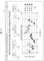
- FIG. 18 is a diagram showing an example of a screen 511 displayed on the terminal device 51 of the second embodiment.
- the dimensional quality evaluation system 5 of Embodiment 2 includes one or more terminal devices 51, an arithmetic processing device 52, and a storage device 53, as in Embodiment 1, which communicate with each other via a communication network 50. connected as possible.
- the user of the dimensional quality evaluation system 5 of the second embodiment inputs the user information, the type of modeling material, and the type of the product 2 in addition to the deformation amount of the sample 1 to the terminal device 51, and inputs the type of the product 2 to the terminal device 51. 52. That is, the terminal device 51 acquires the user information, the type of modeling material, the type of the product 2 and the amount of deformation of the sample 1 . The terminal device 51 transmits the user information, the type of modeling material, the type of the product 2 and the amount of deformation of the sample 1 to the arithmetic processing device 52 .
- the arithmetic processing device 52 stores the type of modeling material, the type of the product 2, and the amount of deformation of the sample 1 transmitted from the terminal device 51 in the storage area of the storage device 53 assigned for each user information.
- the storage device 53 prestores a correlation model for predicting the correlation between the amount of deformation of the product 2 and the amount of deformation of the sample 1 for each type of product 2 and modeling material.
- the storage device 53 pre-stores, for each type of molding material, a dimensional quality determination table T2 that defines the correspondence relationship between the type of the product 2 and the predicted deformation amount of the product 2 and the grade of the dimensional quality of the product 2. ing.
- the arithmetic processing unit 52 reads from the storage device 53 the correlation model corresponding to the type of the product 2 and the type of the modeling material transmitted from the terminal device 51 .
- the arithmetic processing unit 52 inputs the deformation amount of the sample 1 transmitted from the terminal device 51 to the read correlation model, and calculates the predicted value of the deformation amount of the product 2 .
- the arithmetic processing unit 52 reads from the storage device 53 the dimensional quality determination table T2 corresponding to the type of modeling material transmitted from the terminal device 51 .
- the arithmetic processing unit 52 determines the dimensional quality grade corresponding to the type of the product 2 transmitted from the terminal device 51 and the calculated predicted value of the deformation amount of the product 2 using the dimensional quality determination table T2. .
- the processor 52 thereby evaluates the dimensional quality of the product 2 . That is, the processor 52 evaluates the dimensional quality of the product 2 based on the predicted deformation amount of the product 2 calculated by the correlation model.
- the arithmetic processing unit 52 transmits the dimensional quality evaluation result to the terminal device 51 .
- the terminal device 51 displays the evaluation result transmitted from the arithmetic processing device 52 .
- the user can confirm the evaluation results displayed on the terminal device 51 .
- the screen 511 shown in FIG. 18 is different in that an input field 5107 for the type of product 2 is added. Further, screen 511 shown in FIG. 18 differs from screen 510 shown in FIG. 12 in that the dimensional quality evaluation result displayed in display column 5104 is the dimensional quality grade of product 2 .
- the terminal device 51 further acquires the type of the product 2.
- the storage device 53 pre-stores, for each type of product 2, a correlation model that predicts the correlation between the amount of deformation of the product 2 and the amount of deformation of the sample 1 before and after the laminate-manufactured product 2 is separated from the base plate 3. ing.
- the arithmetic processing unit 52 inputs the deformation amount of the sample 1 transmitted from the terminal device 51 to the correlation model corresponding to the type of the product 2 transmitted from the terminal device 51, and obtains a predicted value of the deformation amount of the product 2.
- the dimensional quality of the product 2 is evaluated based on the calculated predicted value.
- the dimensional quality evaluation system 5 of the second embodiment can evaluate the dimensional quality of the product 2 by considering not only factors other than the design shape of the product 2 but also the effects of the design shape of the product 2 on the dimensional quality. can be evaluated. Therefore, the dimensional quality evaluation system 5 of the second embodiment can easily and accurately evaluate the dimensional quality of the laminate-molded body.
- the storage device 53 defines the correspondence relationship between the type of the product 2 and the predicted deformation amount of the product 2, and the dimensional quality grade of the product 2.
- Table T2 is stored in advance.
- the arithmetic processing unit 52 determines the dimensional quality grade corresponding to the type of the product 2 transmitted from the terminal device 51 and the calculated predicted value of the deformation amount of the product 2 using the dimensional quality determination table T2. to assess the dimensional quality of the product 2.
- the dimensional quality evaluation system 5 of Embodiment 2 can accurately evaluate the dimensional quality of the product 2 without using a complicated evaluation algorithm. Therefore, the dimensional quality evaluation system 5 of the second embodiment can more easily and accurately evaluate the dimensional quality of the laminate-molded body.
- the storage device 53 stores the dimensional quality determination table T3 that defines the correspondence between the type of the product 2, the amount of deformation of the sample 1, and the grade of the dimensional quality of the product 2. It may be stored in advance.
- the arithmetic processing unit 52 determines the dimensional quality of the product 2 by using the dimensional quality determination table T3 to determine the dimensional quality grade corresponding to the type of the product 2 and the amount of deformation of the sample 1 transmitted from the terminal device 51. may be evaluated.
- the arithmetic processing unit 52 of the second embodiment can calculate the dimension of the product 2 from the deformation amount of the sample 1 without calculating the predicted value of the deformation amount of the product 2 using the correlation model stored in the storage device 53 .
- a quality grade can be determined directly. Therefore, the arithmetic processing unit 52 of the second embodiment can reduce the processing load when evaluating the dimensional quality of the product 2 compared to the case of using the dimensional quality determination table T2. Therefore, the dimensional quality evaluation system 5 of the second embodiment can more easily and accurately evaluate the dimensional quality of the laminate-molded body.
- Embodiment 3 A dimensional quality evaluation method and evaluation system for a laminate-molded body according to the third embodiment will be described. In the dimensional quality evaluation method and the evaluation system thereof according to Embodiment 3, descriptions of the same configurations and operations as those of Embodiment 1 or Embodiment 2 will be omitted.
- the dimensional quality evaluation method of the third embodiment includes a step of acquiring the dimensional difference between the reference portion 11 and the deformation portion 13 of the laminate-molded sample 1 between steps S1 and S2. That is, the dimensional quality evaluation method of the third embodiment includes a step of acquiring the dimensional difference between the reference portion 11 and the deformed portion 13 in the sample 1 before being separated from the base plate 3 . Specifically, in this step, the height of the upper surface 11a of the reference portion 11 and the height of the upper surface 13a of the deformation portion 13 are measured in the sample 1 before being cut off using the measuring device 4 described above.
- the measured value of the height of the upper surface 11 a of the reference portion 11 is subtracted from the measured value of the height of the upper surface 13 a of the deformed portion 13 . Accordingly, in this step, the dimensional difference between the reference portion 11 and the deformed portion 13 in the sample 1 before being separated can be acquired.
- the dimensional quality evaluation method of Embodiment 3 differs from Embodiments 1 and 2 in the content of Step 3.
- step 3 of the third embodiment the difference value between the dimensional difference between the reference portion 11 and the deformed portion 13 in the sample 1 before being separated and the dimensional difference between the reference portion 11 and the deformed portion 13 in the separated sample 1 is measured.
- the deformation amount of sample 1 is measured.
- the height of the upper surface 11a of the reference portion 11 and the height of the upper surface 13a of the deformation portion 13 are measured in the cut sample 1 using the measuring device 4 described above. do.
- step 3 of the third embodiment the difference value between the dimensional difference between the reference portion 11 and the deformed portion 13 in the sample 1 before being separated and the dimensional difference between the reference portion 11 and the deformed portion 13 in the separated sample 1 can be obtained.
- the dimensional quality evaluation method of the third embodiment can be used even if the height of the upper surface 11a of the reference portion 11 of the sample 1 and the height of the upper surface 13a of the deformable portion 13 are not the same height.
- the deformation amount of the sample 1 can be measured with high accuracy. Therefore, the dimensional quality evaluation method of the third embodiment can more easily and accurately evaluate the dimensional quality of the laminate-molded body.
- the deformation amount of the sample 1 input to the terminal device 51 is the difference between the reference portion 11 and the deformed portion 13 of the sample 1 before being separated, as in step 3 of the third embodiment. It is a difference value between the dimensional difference and the dimensional difference between the reference portion 11 and the deformed portion 13 in the separated sample 1 .
- the dimensional quality evaluation system 5 of the third embodiment can be used even if the height of the upper surface 11a of the reference portion 11 of the sample 1 and the height of the upper surface 13a of the deformable portion 13 are not the same height. , the deformation amount of the sample 1 can be measured with high accuracy, so the dimensional quality of the laminate-molded body can be evaluated more easily and accurately.
- the present invention is not limited to the above-described embodiments, and includes various modifications.
- the above embodiments have been described in detail in order to explain the present invention in an easy-to-understand manner, and are not necessarily limited to those having all the configurations described.
- it is possible to replace part of the configuration of one embodiment with the configuration of another embodiment and it is also possible to add the configuration of another embodiment to the configuration of one embodiment.
- each of the above configurations, functions, processing units, processing means, etc. may be realized by hardware, for example, by designing them in integrated circuits, in part or in whole.
- each of the above configurations, functions, etc. may be realized by software by a processor interpreting and executing a program for realizing each function.
- Information such as programs, tapes, and files that implement each function can be stored in recording devices such as memories, hard disks, SSDs (solid state drives), or recording media such as IC cards, SD cards, and DVDs.
- control lines and information lines indicate what is considered necessary for explanation, and not all control lines and information lines are necessarily indicated on the product. In practice, it may be considered that almost all configurations are interconnected.
Landscapes
- Chemical & Material Sciences (AREA)
- Engineering & Computer Science (AREA)
- Materials Engineering (AREA)
- Physics & Mathematics (AREA)
- Manufacturing & Machinery (AREA)
- General Physics & Mathematics (AREA)
- Mechanical Engineering (AREA)
- Optics & Photonics (AREA)
- Powder Metallurgy (AREA)
- Sampling And Sample Adjustment (AREA)
Priority Applications (2)
| Application Number | Priority Date | Filing Date | Title |
|---|---|---|---|
| EP22890010.6A EP4427912A4 (en) | 2021-11-04 | 2022-11-04 | METHOD FOR EVALUATING DIMENSIONAL QUALITY FOR AN ADDITIVELY MANUFACTURED OBJECT, AND ASSOCIATED EVALUATION SYSTEM |
| JP2023517794A JP7347715B1 (ja) | 2021-11-04 | 2022-11-04 | 積層造形体の寸法品質評価方法及びその評価システム |
Applications Claiming Priority (2)
| Application Number | Priority Date | Filing Date | Title |
|---|---|---|---|
| JP2021-180160 | 2021-11-04 | ||
| JP2021180160 | 2021-11-04 |
Publications (1)
| Publication Number | Publication Date |
|---|---|
| WO2023080190A1 true WO2023080190A1 (ja) | 2023-05-11 |
Family
ID=86241532
Family Applications (1)
| Application Number | Title | Priority Date | Filing Date |
|---|---|---|---|
| PCT/JP2022/041118 Ceased WO2023080190A1 (ja) | 2021-11-04 | 2022-11-04 | 積層造形体の寸法品質評価方法及びその評価システム |
Country Status (3)
| Country | Link |
|---|---|
| EP (1) | EP4427912A4 (cg-RX-API-DMAC7.html) |
| JP (1) | JP7347715B1 (cg-RX-API-DMAC7.html) |
| WO (1) | WO2023080190A1 (cg-RX-API-DMAC7.html) |
Cited By (1)
| Publication number | Priority date | Publication date | Assignee | Title |
|---|---|---|---|---|
| EP4509248A3 (en) * | 2023-08-17 | 2025-03-19 | Proterial, Ltd. | Crack evaluation method of additively manufactured object and crack evaluation device |
Families Citing this family (1)
| Publication number | Priority date | Publication date | Assignee | Title |
|---|---|---|---|---|
| CN119795569B (zh) * | 2024-12-24 | 2025-12-02 | 中国航空工业集团公司成都飞机设计研究所 | 一种基于3d打印的翘曲在线检测方法及系统 |
Citations (5)
| Publication number | Priority date | Publication date | Assignee | Title |
|---|---|---|---|---|
| JP2018103635A (ja) | 2014-09-19 | 2018-07-05 | 株式会社東芝 | 積層造形方法 |
| JP2019217517A (ja) * | 2018-06-18 | 2019-12-26 | 株式会社神戸製鋼所 | 積層造形物の製造方法、及び積層造形物の検査方法 |
| JP2020114677A (ja) | 2014-06-05 | 2020-07-30 | ザ・ボーイング・カンパニーThe Boeing Company | 付加製造における歪みの予測及び最小化 |
| JP2020172106A (ja) * | 2019-04-10 | 2020-10-22 | コンセプト・レーザー・ゲゼルシャフト・ミト・ベシュレンクテル・ハフツング | 三次元物体を付加的に製造する装置及び当該装置の照射装置を較正する方法 |
| JP2021094775A (ja) | 2019-12-17 | 2021-06-24 | セイコーエプソン株式会社 | 三次元造形装置及び三次元造形方法 |
Family Cites Families (3)
| Publication number | Priority date | Publication date | Assignee | Title |
|---|---|---|---|---|
| US10124410B2 (en) * | 2010-09-25 | 2018-11-13 | Ipg Photonics Corporation | Methods and systems for coherent imaging and feedback control for modification of materials |
| GB2549071B (en) * | 2016-03-23 | 2020-11-11 | Sony Interactive Entertainment Inc | 3D printing system |
| WO2018200383A1 (en) * | 2017-04-24 | 2018-11-01 | Desktop Metal, Inc. | Three-dimensional (3d) printing using measured processing effects with feedback to processing parameters |
-
2022
- 2022-11-04 JP JP2023517794A patent/JP7347715B1/ja active Active
- 2022-11-04 WO PCT/JP2022/041118 patent/WO2023080190A1/ja not_active Ceased
- 2022-11-04 EP EP22890010.6A patent/EP4427912A4/en active Pending
Patent Citations (5)
| Publication number | Priority date | Publication date | Assignee | Title |
|---|---|---|---|---|
| JP2020114677A (ja) | 2014-06-05 | 2020-07-30 | ザ・ボーイング・カンパニーThe Boeing Company | 付加製造における歪みの予測及び最小化 |
| JP2018103635A (ja) | 2014-09-19 | 2018-07-05 | 株式会社東芝 | 積層造形方法 |
| JP2019217517A (ja) * | 2018-06-18 | 2019-12-26 | 株式会社神戸製鋼所 | 積層造形物の製造方法、及び積層造形物の検査方法 |
| JP2020172106A (ja) * | 2019-04-10 | 2020-10-22 | コンセプト・レーザー・ゲゼルシャフト・ミト・ベシュレンクテル・ハフツング | 三次元物体を付加的に製造する装置及び当該装置の照射装置を較正する方法 |
| JP2021094775A (ja) | 2019-12-17 | 2021-06-24 | セイコーエプソン株式会社 | 三次元造形装置及び三次元造形方法 |
Non-Patent Citations (1)
| Title |
|---|
| See also references of EP4427912A4 |
Cited By (1)
| Publication number | Priority date | Publication date | Assignee | Title |
|---|---|---|---|---|
| EP4509248A3 (en) * | 2023-08-17 | 2025-03-19 | Proterial, Ltd. | Crack evaluation method of additively manufactured object and crack evaluation device |
Also Published As
| Publication number | Publication date |
|---|---|
| JP7347715B1 (ja) | 2023-09-20 |
| EP4427912A4 (en) | 2025-10-08 |
| EP4427912A1 (en) | 2024-09-11 |
| JPWO2023080190A1 (cg-RX-API-DMAC7.html) | 2023-05-11 |
Similar Documents
| Publication | Publication Date | Title |
|---|---|---|
| Armillotta et al. | Warpage of FDM parts: Experimental tests and analytic model | |
| JP7347715B1 (ja) | 積層造形体の寸法品質評価方法及びその評価システム | |
| CN114818401A (zh) | 机器学习模型的训练方法、训练装置、评价系统 | |
| Singh | Some investigations for small‐sized product fabrication with FDM for plastic components | |
| Gao et al. | An experimental and modeling study on warping in additively manufactured overhang structures | |
| US20160169821A1 (en) | Method of quality assurance of an additive manufacturing build process | |
| JP6904812B2 (ja) | 金型寿命判定装置、及びプレス成形物の製造方法 | |
| JP2020001302A (ja) | 造形予測システム、造形予測表示システム、情報処理装置およびプログラム | |
| US20210080930A1 (en) | Additive-Manufactured Object Design Supporting Device and Additive-Manufactured Object Design Supporting Method | |
| Douellou et al. | Assessment of geometrical defects caused by thermal distortions in laser-beam-melting additive manufacturing: a simulation approach | |
| US20210039323A1 (en) | Verification of additive manufacturing processes | |
| JP7590646B2 (ja) | プレス機の剛性予測方法 | |
| JP2024119167A (ja) | 成形管理システム | |
| Akande et al. | Process control testing for fused filament fabrication | |
| JP4855866B2 (ja) | 射出成形解析方法、そり変形解析方法およびその装置 | |
| Clark et al. | Validation of a finite element model for fused filament fabrication additive manufacturing | |
| CN116050220B (zh) | 基于sdas分布的转向节疲劳耐久仿真分析方法与装置 | |
| JP2021094698A (ja) | 造形データ作成装置および造形データ作成プログラム | |
| JP7541241B2 (ja) | プレス成形シミュレーション方法 | |
| JP3356660B2 (ja) | 有限要素法を用いた構造体の反り状態解析方法およびシステム、有限要素法を用いた構造体の反り状態解析プログラムを記録した記録媒体 | |
| Dash et al. | A combined experimental–numerical approach for predicting young’s modulus in additively manufactured thin strut-based structures | |
| JP4590834B2 (ja) | 面品質評価装置及び評価プログラム | |
| WO2023068268A1 (ja) | 付加製造試験体の変形部の変形量の測定方法及び付加製造の適正条件の決定方法 | |
| KR102091815B1 (ko) | 지능형 초정밀 플라스틱 금형 설계장치 | |
| He et al. | Investigation on Bridging Defects in 3D-Printed Polylactic Acid Beams Using Fused Filament Fabrication |
Legal Events
| Date | Code | Title | Description |
|---|---|---|---|
| WWE | Wipo information: entry into national phase |
Ref document number: 2023517794 Country of ref document: JP |
|
| 121 | Ep: the epo has been informed by wipo that ep was designated in this application |
Ref document number: 22890010 Country of ref document: EP Kind code of ref document: A1 |
|
| WWE | Wipo information: entry into national phase |
Ref document number: 2022890010 Country of ref document: EP |
|
| NENP | Non-entry into the national phase |
Ref country code: DE |
|
| ENP | Entry into the national phase |
Ref document number: 2022890010 Country of ref document: EP Effective date: 20240604 |