WO2023079941A1 - 情報処理装置および情報処理方法 - Google Patents
情報処理装置および情報処理方法 Download PDFInfo
- Publication number
- WO2023079941A1 WO2023079941A1 PCT/JP2022/038659 JP2022038659W WO2023079941A1 WO 2023079941 A1 WO2023079941 A1 WO 2023079941A1 JP 2022038659 W JP2022038659 W JP 2022038659W WO 2023079941 A1 WO2023079941 A1 WO 2023079941A1
- Authority
- WO
- WIPO (PCT)
- Prior art keywords
- camera
- information processing
- user
- tolerance
- unit
- Prior art date
- Legal status (The legal status is an assumption and is not a legal conclusion. Google has not performed a legal analysis and makes no representation as to the accuracy of the status listed.)
- Ceased
Links
Images



Classifications
-
- G—PHYSICS
- G06—COMPUTING OR CALCULATING; COUNTING
- G06F—ELECTRIC DIGITAL DATA PROCESSING
- G06F3/00—Input arrangements for transferring data to be processed into a form capable of being handled by the computer; Output arrangements for transferring data from processing unit to output unit, e.g. interface arrangements
- G06F3/01—Input arrangements or combined input and output arrangements for interaction between user and computer
- G06F3/011—Arrangements for interaction with the human body, e.g. for user immersion in virtual reality
- G06F3/013—Eye tracking input arrangements
-
- G—PHYSICS
- G03—PHOTOGRAPHY; CINEMATOGRAPHY; ANALOGOUS TECHNIQUES USING WAVES OTHER THAN OPTICAL WAVES; ELECTROGRAPHY; HOLOGRAPHY
- G03B—APPARATUS OR ARRANGEMENTS FOR TAKING PHOTOGRAPHS OR FOR PROJECTING OR VIEWING THEM; APPARATUS OR ARRANGEMENTS EMPLOYING ANALOGOUS TECHNIQUES USING WAVES OTHER THAN OPTICAL WAVES; ACCESSORIES THEREFOR
- G03B15/00—Special procedures for taking photographs; Apparatus therefor
-
- G—PHYSICS
- G03—PHOTOGRAPHY; CINEMATOGRAPHY; ANALOGOUS TECHNIQUES USING WAVES OTHER THAN OPTICAL WAVES; ELECTROGRAPHY; HOLOGRAPHY
- G03B—APPARATUS OR ARRANGEMENTS FOR TAKING PHOTOGRAPHS OR FOR PROJECTING OR VIEWING THEM; APPARATUS OR ARRANGEMENTS EMPLOYING ANALOGOUS TECHNIQUES USING WAVES OTHER THAN OPTICAL WAVES; ACCESSORIES THEREFOR
- G03B19/00—Cameras
- G03B19/02—Still-picture cameras
- G03B19/04—Roll-film cameras
- G03B19/07—Roll-film cameras having more than one objective
-
- G—PHYSICS
- G06—COMPUTING OR CALCULATING; COUNTING
- G06T—IMAGE DATA PROCESSING OR GENERATION, IN GENERAL
- G06T3/00—Geometric image transformations in the plane of the image
- G06T3/40—Scaling of whole images or parts thereof, e.g. expanding or contracting
-
- G—PHYSICS
- G06—COMPUTING OR CALCULATING; COUNTING
- G06T—IMAGE DATA PROCESSING OR GENERATION, IN GENERAL
- G06T7/00—Image analysis
- G06T7/20—Analysis of motion
-
- G—PHYSICS
- G06—COMPUTING OR CALCULATING; COUNTING
- G06T—IMAGE DATA PROCESSING OR GENERATION, IN GENERAL
- G06T7/00—Image analysis
- G06T7/70—Determining position or orientation of objects or cameras
-
- G—PHYSICS
- G06—COMPUTING OR CALCULATING; COUNTING
- G06V—IMAGE OR VIDEO RECOGNITION OR UNDERSTANDING
- G06V40/00—Recognition of biometric, human-related or animal-related patterns in image or video data
- G06V40/10—Human or animal bodies, e.g. vehicle occupants or pedestrians; Body parts, e.g. hands
- G06V40/16—Human faces, e.g. facial parts, sketches or expressions
- G06V40/161—Detection; Localisation; Normalisation
-
- H—ELECTRICITY
- H04—ELECTRIC COMMUNICATION TECHNIQUE
- H04N—PICTORIAL COMMUNICATION, e.g. TELEVISION
- H04N23/00—Cameras or camera modules comprising electronic image sensors; Control thereof
- H04N23/45—Cameras or camera modules comprising electronic image sensors; Control thereof for generating image signals from two or more image sensors being of different type or operating in different modes, e.g. with a CMOS sensor for moving images in combination with a charge-coupled device [CCD] for still images
-
- H—ELECTRICITY
- H04—ELECTRIC COMMUNICATION TECHNIQUE
- H04N—PICTORIAL COMMUNICATION, e.g. TELEVISION
- H04N23/00—Cameras or camera modules comprising electronic image sensors; Control thereof
- H04N23/60—Control of cameras or camera modules
-
- H—ELECTRICITY
- H04—ELECTRIC COMMUNICATION TECHNIQUE
- H04N—PICTORIAL COMMUNICATION, e.g. TELEVISION
- H04N23/00—Cameras or camera modules comprising electronic image sensors; Control thereof
- H04N23/60—Control of cameras or camera modules
- H04N23/61—Control of cameras or camera modules based on recognised objects
- H04N23/611—Control of cameras or camera modules based on recognised objects where the recognised objects include parts of the human body
-
- H—ELECTRICITY
- H04—ELECTRIC COMMUNICATION TECHNIQUE
- H04N—PICTORIAL COMMUNICATION, e.g. TELEVISION
- H04N23/00—Cameras or camera modules comprising electronic image sensors; Control thereof
- H04N23/60—Control of cameras or camera modules
- H04N23/64—Computer-aided capture of images, e.g. transfer from script file into camera, check of taken image quality, advice or proposal for image composition or decision on when to take image
-
- H—ELECTRICITY
- H04—ELECTRIC COMMUNICATION TECHNIQUE
- H04N—PICTORIAL COMMUNICATION, e.g. TELEVISION
- H04N23/00—Cameras or camera modules comprising electronic image sensors; Control thereof
- H04N23/60—Control of cameras or camera modules
- H04N23/667—Camera operation mode switching, e.g. between still and video, sport and normal or high- and low-resolution modes
-
- H—ELECTRICITY
- H04—ELECTRIC COMMUNICATION TECHNIQUE
- H04N—PICTORIAL COMMUNICATION, e.g. TELEVISION
- H04N23/00—Cameras or camera modules comprising electronic image sensors; Control thereof
- H04N23/60—Control of cameras or camera modules
- H04N23/69—Control of means for changing angle of the field of view, e.g. optical zoom objectives or electronic zooming
-
- H—ELECTRICITY
- H04—ELECTRIC COMMUNICATION TECHNIQUE
- H04N—PICTORIAL COMMUNICATION, e.g. TELEVISION
- H04N23/00—Cameras or camera modules comprising electronic image sensors; Control thereof
- H04N23/60—Control of cameras or camera modules
- H04N23/695—Control of camera direction for changing a field of view, e.g. pan, tilt or based on tracking of objects
-
- H—ELECTRICITY
- H04—ELECTRIC COMMUNICATION TECHNIQUE
- H04N—PICTORIAL COMMUNICATION, e.g. TELEVISION
- H04N23/00—Cameras or camera modules comprising electronic image sensors; Control thereof
- H04N23/90—Arrangement of cameras or camera modules, e.g. multiple cameras in TV studios or sports stadiums
-
- G—PHYSICS
- G06—COMPUTING OR CALCULATING; COUNTING
- G06T—IMAGE DATA PROCESSING OR GENERATION, IN GENERAL
- G06T2207/00—Indexing scheme for image analysis or image enhancement
- G06T2207/30—Subject of image; Context of image processing
- G06T2207/30196—Human being; Person
- G06T2207/30201—Face
Definitions
- the present disclosure relates to an information processing device and an information processing method.
- a camera When installing a camera on a terminal with limited thickness, such as a smartphone, multiple cameras such as wide-angle and telephoto are used according to the zoom magnification. Also, there is known a technique for generating a high-quality composite image by executing a process of combining a color image and a black-and-white image captured from different viewpoints.
- the present disclosure proposes an information processing device and an information processing method that make it difficult to notice switching between a plurality of cameras.
- an information processing apparatus includes a detection unit that detects a relative position between a user who causes one of a plurality of cameras to capture an image and the sensor, based on data detected by a sensor; a first calculation unit that calculates a degree of tolerance indicating the user's difficulty in noticing switching between cameras that capture images based on; and a selection unit for selecting.
- FIG. 4 is a diagram showing an example of an imaging range of a rear camera; 6 is a flowchart showing an example of camera switching processing; It is a figure which shows an example of a structure of the information processing apparatus which concerns on a modification.
- 1 is a hardware configuration diagram showing an example of a computer that implements functions of an information processing apparatus; FIG.
- Embodiment 1-1 Configuration of Information Processing Apparatus According to Embodiment 1-2.
- Information processing procedure according to the embodiment 2 Modified example of embodiment 3.
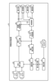
- FIG. 1 is a diagram illustrating an example of the configuration of an information processing device according to an embodiment of the present disclosure.
- information processing apparatus 10 includes front camera 11, rear cameras 12 and 13, display unit 14, operation unit 15, communication unit 16, storage unit 20, detection unit 21, It has a first calculation unit 22 , a camera control unit 23 , a second calculation unit 24 , a selection unit 25 , a switching unit 26 , an electronic zoom unit 27 , an image processing unit 28 , and a control unit 29 .
- Examples of the information processing device 10 include a smartphone.
- the front camera 11 is provided on the front side where the display unit 14 and the operation unit 15 of the information processing device 10 are arranged, and can capture an image of the face of the user who operates the information processing device 10 .
- the front camera 11 captures an image using, for example, a CMOS (Complementary Metal Oxide Semiconductor) image sensor or a CCD (Charge Coupled Device) image sensor as an imaging device.
- the front camera 11 photoelectrically converts the light received by the imaging device and performs A/D (Analog/Digital) conversion to generate an image.
- the front camera 11 outputs the captured image to the detection section 21 .
- the front camera 11 is an example of a first camera. Although not shown, the captured image output from the front camera 11 may be input to the electronic zoom section 27 and the image processing section 28 .
- the rear cameras 12 and 13 are provided on the back side of the information processing device 10, and can capture images of subjects.
- the rear cameras 12 and 13 capture images using, for example, CMOS image sensors or CCD image sensors as imaging elements.
- the rear cameras 12 and 13 photoelectrically convert the light received by the imaging device and perform A/D conversion to generate an image.
- Rear cameras 12 and 13 output captured images to switching unit 26 .
- the rear camera 12 and the rear camera 13 are cameras with different magnifications. In the following description, as an example, it is assumed that the magnification of the rear camera 12 is 1 ⁇ and the magnification of the rear camera 13 is 2 ⁇ .
- the rear cameras 12 and 13 may be not only fixed-magnification cameras, but also cameras capable of optical zoom.
- the rear cameras 12 and 13 are examples of a second camera and a third camera, respectively. Also, the number of rear cameras may be three or more.
- FIG. 2 is a diagram showing an example of the imaging range of the rear camera.
- the rear camera 12 and the rear camera 13 are arranged at different positions on the back surface of the information processing device 10, and therefore have different imaging ranges.
- the imaging range 12a of the rear camera 12 and the imaging range 13a of the rear camera 13 are different ranges, although they partially overlap.
- the line of sight shifts based on the parallax between the two images, which makes the user who observes the images feel uncomfortable.
- the movement of the captured image or the movement of the camera is detected by a gyro sensor, etc., and the camera is switched at a timing that is difficult for the user to notice according to the detected movement.
- the camera is moving in the captured image, the gyro sensor, etc., but the relative position between the user and the camera does not change, and the camera is moving as seen from the user. Because there is no camera, you may notice the switching of the camera.
- the information processing apparatus 10 makes it difficult for the user who owns the information processing apparatus 10 equipped with a camera to notice switching between multiple cameras while moving. information processing to be performed. Specifically, information processing apparatus 10 detects the relative position between front camera 11 and the user based on the position of the user's face imaged by front camera 11 . The information processing apparatus 10 calculates a tolerance indicating the difficulty of noticing the user based on the detected relative position. Information processing apparatus 10 selects rear cameras 12 and 13 for imaging the subject based on the calculated tolerance.
- the display unit 14 is a display device for displaying various information.
- the display unit 14 is realized by, for example, a liquid crystal display, an organic EL (Electro Luminescence) display, or the like as a display device.
- the display unit 14 displays various screens such as captured images input from the image processing unit 28 and display screens input from the control unit 29 .
- the operation unit 15 is an input device that receives various operations from the user of the information processing device 10 .
- the operation unit 15 is implemented by, for example, a touch panel as an input device.
- the display device of the display unit 14 and the input device of the operation unit 15 are integrated.
- the communication unit 16 is realized, for example, by a communication module or the like compatible with a wireless LAN (Local Area Network) such as Wi-Fi (registered trademark) or third to fifth generation mobile communication systems (3G to 5G).
- the communication unit 16 is a communication interface that controls communication of information with other information processing devices and the like.
- the storage unit 20 is implemented by, for example, a RAM (Random Access Memory), a semiconductor memory device such as flash memory, or a storage device such as a hard disk or optical disk.
- the storage unit 20 stores captured images and the like processed by the image processing unit 28 .
- the storage unit 20 also stores information (programs and data) used for processing in the control unit 29 .
- a CPU Central Processing Unit
- MPU Micro Processing Unit
- the detection unit 21 to the control unit 29 may be realized by an integrated circuit such as ASIC (Application Specific Integrated Circuit) or FPGA (Field Programmable Gate Array).
- the detection unit 21 detects the position of the user's face from the captured image.
- the detection unit 21 detects the position of the user's face three-dimensionally or two-dimensionally.
- the detection unit 21 detects the relative position between the front camera 11 and the user based on the detected face position.
- the detection unit 21 may use a distance measuring sensor such as a TOF (Time Of Flight) sensor instead of the captured image to obtain the position of the face from the distance to the user's face.
- the relative position is, for example, information including the coordinates of the position of the face within the captured image.
- the detection unit 21 outputs the detected relative position between the front camera 11 and the user to the first calculation unit 22 .
- the first calculation unit 22 calculates, based on the relative position, a degree of tolerance indicating the user's difficulty in noticing the switching of the imaging camera. do.
- the first calculator 22 calculates the tolerance according to, for example, the moving speed of the face position based on the coordinates of the face position included in the relative position. For example, the first calculator 22 calculates the tolerance such that the faster the moving speed of the face position, the larger the tolerance.
- the first calculator 22 may calculate the tolerance according to the acceleration of the position of the face. For example, the first calculator 22 may calculate the tolerance such that the greater the acceleration of the position of the face, the greater the tolerance.
- the first calculator 22 outputs the calculated tolerance to the selector 25 .
- the camera control unit 23 calculates the zoom magnification desired by the user according to the user's operation information input from the control unit 29 .
- Camera control section 23 outputs the calculated zoom magnification to second calculation section 24 and electronic zoom section 27 .
- the zoom magnification output by the camera control section 23 is reflected in the zoom magnification of the image currently being captured in the electronic zoom section 27 .
- the second calculation unit 24 calculates the rear camera 12 and the rear camera based on the input zoom magnification and the preset zoom magnification required to switch the camera. 13 is calculated. For example, during imaging with the rear camera 12 having a magnification of 1x, the zoom operation is performed by electronic zoom so that the zoom magnification increases from 1x. Switching to the camera 13 improves the image quality.
- the second calculator 24 calculates the degree of necessity of switching so that the degree of necessity of switching becomes high in such a case. The second calculator 24 also determines the camera to switch to.
- the degree of necessity of switching is, for example, the reciprocal of the absolute difference (1/
- the necessity of switching may be given hysteresis by giving an offset value to the difference value. For example, when the zoom magnification is increased, the necessity of switching is set to (1/
- the captured image of the rear camera 12 is zoomed in to 1 to 2.2 times, and switched to the rear camera 13 at 2.2 times.
- the zoom magnification is decreased, the captured image of the rear camera 13 is zoomed out from a magnification exceeding 2.2 times to 2 times, and switched to the rear camera 12 at 2 times.
- the second calculation unit 24 outputs the calculated degree of necessity of switching and the camera to be switched to to the selection unit 25 .
- the selection unit 25 receives the degree of tolerance from the first calculation unit 22 and the necessity of switching and the camera to switch to from the second calculation unit 24 .
- the selection unit 25 selects the rear camera 12 or the rear camera 13 based on the degree of tolerance, the necessity of switching, and the camera to switch to, and outputs a camera selection signal designating the selected camera to the switching unit 26 .
- the selection unit 25 multiplies the tolerance by the degree of necessity of switching, and selects the rear camera 12 or the rear camera 13 so as to switch the camera during imaging if the result is equal to or greater than a predetermined threshold.
- the selection unit 25 sets a value equal to or less than the value obtained by multiplying the minimum value of the tolerance by the maximum value of the necessity of switching as a switching threshold, so that when the necessity of switching reaches the maximum value, the camera is turned on. can be switched. For example, if the selection unit 25 sets the tolerance value range from 1 to 100, the switching necessity value range from 1 to 100, and the threshold value to 100 or less, when the switching necessity value becomes 100, the threshold value As described above, the camera can be switched.
- the switching unit 26 switches the captured image (video signal) output to the electronic zoom unit 27 to the captured image of the rear camera 12 or the rear camera 13 designated by the camera selection signal. switch to The switching unit 26 outputs the camera information and the captured image after switching to the electronic zoom unit 27 .
- the camera information includes information on the optical magnification of the camera that is being switched and selected.
- the electronic zoom section 27 receives a zoom magnification from the camera control section 23 and receives camera information and a captured image from the switching section 26 .
- the electronic zoom unit 27 determines the electronic zoom magnification based on the input zoom magnification and the optical magnification included in the camera information.
- the electronic zoom unit 27 performs electronic zoom processing with the determined electronic zoom magnification on the captured image.
- the electronic zoom section 27 outputs the captured image after the electronic zoom to the image processing section 28 .
- the image processing section 28 When the captured image is input from the electronic zoom section 27, the image processing section 28 performs various types of image processing on the captured image, and causes the display section 14 to display the captured image after the image processing. Note that image processing includes, for example, adjustment of contrast, brightness, and the like. Further, when the control unit 29 instructs the image processing unit 28 to store the captured image, the image processing unit 28 stores the captured image after the image processing in the storage unit 20 .
- the control unit 29 controls each unit of the information processing device 10 .
- the control unit 29 receives a user's operation input from the operation unit 15 via a user interface displayed on the display unit 14 .
- the control unit 29 executes processing according to the received operation input. For example, upon receiving a pinch-out operation for enlarging a captured image from the user, the control unit 29 outputs the pinch-out operation to the camera control unit 23 as user operation information. Further, the control unit 29 instructs the image processing unit 28 to perform image processing and save captured images. Furthermore, the control unit 29 may transmit the captured image stored in the storage unit 20 to another information processing device via the communication unit 16 .
- FIG. 3 is a flowchart illustrating an example of camera switching processing.
- the control unit 29 of the information processing device 10 starts photographing with the front camera 11 and the rear cameras 12 and 13 based on instructions from the user.
- the detection unit 21 detects the position of the user's face from the captured image.
- the detection unit 21 detects the relative position between the front camera 11 and the user based on the detected face position (step S1).
- the detection unit 21 outputs the detected relative position between the front camera 11 and the user to the first calculation unit 22 .
- the first calculator 22 calculates the tolerance based on the relative position (step S2).
- the first calculator 22 outputs the calculated tolerance to the selector 25 .
- the camera control unit 23 calculates the zoom magnification desired by the user according to the user's operation information (step S3). Camera control section 23 outputs the calculated zoom magnification to second calculation section 24 and electronic zoom section 27 .
- the second calculation unit 24 calculates the rear camera 12 and the rear camera based on the input zoom magnification and the preset zoom magnification required to switch the camera. 13 is calculated (step S4).
- the second calculator 24 outputs the calculated necessity of switching to the selector 25 .
- the selection unit 25 receives the tolerance from the first calculation unit 22 and the necessity of switching from the second calculation unit 24 .
- the selection unit 25 determines whether or not the value obtained by multiplying the tolerance by the necessity of switching is equal to or greater than a threshold (step S5). If the selection unit 25 determines that the value obtained by multiplying the degree of tolerance by the necessity of switching is equal to or greater than the threshold (step S5: Yes), the selection unit 25 selects the rear camera 12 or the rear camera 13 to be switched, and designates the selected camera.
- a camera selection signal for switching is output to the switching unit 26 .
- step S5 determines that the value obtained by multiplying the degree of tolerance by the degree of necessity of switching is less than the threshold value (step S5: No), it continues to select the camera currently in use. Without outputting to the switching unit 26, the process proceeds to step S7.
- the switching unit 26 switches the captured image to be output to the electronic zoom unit 27 to the captured image of the rear camera 12 or the rear camera 13 designated by the camera selection signal (step S6).
- the switching unit 26 outputs the camera information and the captured image after switching to the electronic zoom unit 27 . Note that, when the currently used camera is selected again, the switching unit 26 outputs the camera information and the captured image of the currently used camera to the electronic zoom unit 27 .
- the electronic zoom unit 27 determines the electronic zoom magnification based on the input zoom magnification and the optical magnification included in the camera information.
- the electronic zoom unit 27 performs electronic zoom processing with the determined electronic zoom magnification on the captured image.
- the electronic zoom section 27 outputs the captured image after the electronic zoom to the image processing section 28 .
- the image processing section 28 performs various types of image processing on the captured image, and causes the display section 14 to display the captured image after the image processing.
- the control unit 29 stores the captured image being displayed in the storage unit 20 and saves it.
- the control unit 29 determines whether or not the user has input an instruction to end shooting (step S7).
- step S7: No the process returns to step S1 to continue shooting. If the control unit 29 determines that the user has input an instruction to end shooting (step S7: Yes), the control unit 29 ends the camera switching process. As a result, it is possible to make it difficult to notice the switching of a plurality of cameras.
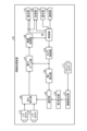
- FIG. 4 is a diagram showing an example of the configuration of an information processing device according to a modification.
- An information processing apparatus 50 shown in FIG. 4 has a line-of-sight detection unit 51 and a first calculation unit 52 instead of the detection unit 21 and the first calculation unit 22 of the information processing apparatus 10 described above.
- the line-of-sight detection unit 51 detects the position of the user's eyes and the line of sight from the captured image.
- the line-of-sight detection unit 51 detects the relative position between the front camera 11 and the user based on the detected eye position.
- the relative position is information including, for example, coordinates of eye positions in the captured image.
- the line-of-sight detection unit 51 outputs the detected relative position between the front camera 11 and the user and line-of-sight information to the first calculation unit 52 .
- the first calculation unit 52 calculates an allowance indicating the difficulty of noticing the user based on the relative position and the line-of-sight information. do.
- the first calculator 52 calculates the tolerance according to, for example, the movement speed of the eye position based on the coordinates of the eye position included in the relative position and the line-of-sight information. For example, the first calculator 52 calculates the tolerance such that the faster the movement speed of the eye position and the more the line of sight in the line of sight information deviates from the center of the display unit 14, the larger the tolerance. do.
- the first calculator 52 may calculate the tolerance such that the faster the movement speed of the line of sight is, the larger the tolerance is. Also, the first calculator 52 may calculate the tolerance according to the acceleration of the eye position and the line-of-sight information. The first calculator 22 outputs the calculated tolerance to the selector 25 . In this way, by using the position of the user's eyes and the line of sight, the relative position between the front camera 11 and the user can be detected. , 13 can be switched.
- processing according to the above-described embodiments may be implemented in various different forms other than the above-described embodiments.
- a smart phone is used as an example of the information processing device 10, but the information processing device 10 is not limited to this.
- it may be applied to an in-vehicle camera such as a back monitor or a camera such as an intercom.
- each component of each device illustrated is functionally conceptual and does not necessarily need to be physically configured as illustrated.
- the specific form of distribution and integration of each device is not limited to the one shown in the figure, and all or part of them can be functionally or physically distributed and integrated in arbitrary units according to various loads and usage conditions. Can be integrated and configured.
- the camera control section 23 and the control section 29 may be integrated.
- FIG. 5 is a hardware configuration diagram showing an example of a computer that implements the functions of the information processing apparatus.
- Computer 1000 has CPU 1100 , RAM 1200 , ROM (Read Only Memory) 1300 , HDD (Hard Disk Drive) 1400 , communication interface 1500 and input/output interface 1600 .
- Each part of computer 1000 is connected by bus 1050 .
- the CPU 1100 operates based on programs stored in the ROM 1300 or HDD 1400 and controls each section. For example, the CPU 1100 loads programs stored in the ROM 1300 or HDD 1400 into the RAM 1200 and executes processes corresponding to various programs.
- the ROM 1300 stores a boot program such as BIOS (Basic Input Output System) executed by the CPU 1100 when the computer 1000 is started, and programs dependent on the hardware of the computer 1000.
- BIOS Basic Input Output System
- the HDD 1400 is a computer-readable recording medium that non-temporarily records programs executed by the CPU 1100 and data used by such programs.
- HDD 1400 is a recording medium that records an information processing program according to the present disclosure, which is an example of program data 1450 .
- a communication interface 1500 is an interface for connecting the computer 1000 to an external network 1550 (for example, the Internet).
- the CPU 1100 receives data from another device via the communication interface 1500, and transmits data generated by the CPU 1100 to another device.
- the input/output interface 1600 is an interface for connecting the input/output device 1650 and the computer 1000 .
- the CPU 1100 receives data from input devices such as a keyboard and mouse via the input/output interface 1600 .
- the CPU 1100 transmits data to an output device such as a display, a speaker, or a printer via the input/output interface 1600 .
- the input/output interface 1600 may function as a media interface for reading a program or the like recorded on a predetermined recording medium.
- Media include, for example, optical recording media such as DVD (Digital Versatile Disc) and PD (Phase change rewritable disk), magneto-optical recording media such as MO (Magneto-Optical disk), tape media, magnetic recording media, semiconductor memories, etc. is.
- optical recording media such as DVD (Digital Versatile Disc) and PD (Phase change rewritable disk)
- magneto-optical recording media such as MO (Magneto-Optical disk)
- tape media magnetic recording media
- magnetic recording media semiconductor memories, etc. is.
- the CPU 1100 of the computer 1000 implements the functions of the detection unit 21 and the like by executing the information processing program loaded on the RAM 1200.
- the HDD 1400 also stores an information processing program according to the present disclosure, data of the storage unit 20 and the like.
- CPU 1100 reads and executes program data 1450 from HDD 1400 , as another example, these programs may be obtained from another device via external network 1550 .
- the information processing device 10 has a detection unit 21 , a first calculation unit 22 and a selection unit 25 .
- the detection unit 21 detects the relative position between the sensor and the user whose image is captured by one of the plurality of cameras (rear cameras 12 and 13) based on data detected by the sensor.
- the first calculator 22 calculates a degree of tolerance that indicates how difficult it is for the user to notice the switching of the imaging camera.
- the selection unit 25 selects a camera for imaging the subject from a plurality of cameras based on the calculated tolerance. As a result, switching between a plurality of cameras can be made difficult to notice.
- the sensor is the first camera (front camera 11), and the detection unit 21 detects the relative position based on the position of the user's face captured by the first camera. As a result, switching between a plurality of cameras can be made difficult to notice.
- the first calculator 22 calculates the tolerance according to the moving speed of the face position. As a result, the fact that the user is not gazing at the display unit 14 of the information processing device 10 can be expressed as a degree of tolerance.
- the plurality of cameras includes a second camera (rear camera 12) and a third camera (rear camera 13) with different magnifications
- the information processing device 10 further includes a second calculator 24.
- the second calculator 24 calculates the second camera and the third camera based on the first zoom magnification for switching between the second camera and the third camera and the second zoom magnification of the image being captured. Calculate the degree of necessity of switching between cameras. As a result, the camera can be switched according to the necessity of camera switching.
- the selection unit 25 selects the second camera or the third camera based on the tolerance and necessity. As a result, you can switch between cameras as per your tolerance and need.
- the selection unit 25 sets a value equal to or less than the value obtained by multiplying the minimum value of tolerance by the maximum value of necessity as a switching threshold in selecting the second camera and the third camera. As a result, the camera can be switched when the degree of necessity is the maximum value.
- the second calculation unit 24 calculates the degree of necessity with hysteresis. As a result, frequent camera switching can be suppressed.
- the sensor is a distance measuring sensor, and the detection unit 21 detects the relative position based on the position of the face obtained from the distance to the user's face measured by the distance measuring sensor. As a result, switching between a plurality of cameras can be made difficult to notice.
- the first calculator 22 calculates the tolerance according to the acceleration of the face position. As a result, the fact that the user is not gazing at the display unit 14 of the information processing device 10 can be expressed as a degree of tolerance.
- the sensor is a first camera
- the detection unit line-of-sight detection unit 51
- the calculation unit 52 calculates a tolerance indicating the difficulty of noticing the user based on the relative position and line of sight. As a result, switching between a plurality of cameras can be made difficult to notice.
- the information processing apparatus 10 further has an electronic zoom unit 27 that electronically zooms the captured image output from the selected second camera or third camera. As a result, electronic zoom can be performed on the captured image.
- the second zoom magnification is a magnification based on the magnification of the second camera or the third camera and the magnification of the electronic zoom. As a result, zooming can be performed by combining the optical magnification and the electronic zoom magnification.
- the present technology can also take the following configuration.
- a user that causes one of a plurality of cameras to take an image based on data detected by the sensor; and a detection unit that detects a relative position to the sensor; a first calculation unit that calculates, based on the relative position, a degree of tolerance indicating the user's difficulty in noticing switching cameras for imaging; a selection unit that selects a camera for imaging a subject from the plurality of cameras based on the calculated tolerance;
- the information processing device includes a second camera and a third camera with different magnifications, Further, based on a first zoom magnification for switching between the second camera and the third camera and a second zoom magnification of an image being captured, the second camera and the third camera are selected. Having a second calculation unit that calculates the degree of necessity of switching with the camera, The information processing apparatus according to any one of (1) to (3) above. (5) The selection unit selects the second camera or the third camera based on the tolerance and the necessity. The information processing device according to (4) above.
- the selection unit sets a value equal to or less than a value obtained by multiplying the minimum value of the tolerance by the maximum value of the necessity as a threshold value for switching between the second camera and the third camera,
- the information processing device according to (5) above.
- the second calculation unit calculates the necessity with hysteresis.
- the information processing apparatus according to (4) or (5).
- the sensor is a ranging sensor, The detection unit detects the relative position based on the position of the face obtained from the distance to the user's face measured by the distance measuring sensor.
- the first calculation unit calculates the tolerance according to the acceleration of the position of the face.
- the information processing device according to (2) above.
- the sensor is a first camera;
- the detection unit detects the relative position and the line of sight based on the position of the user's eyes captured by the first camera,
- the first calculation unit calculates a tolerance indicating the difficulty of noticing the user based on the relative position and the line of sight.
- the information processing device according to (1) above.
- an electronic zoom unit that electronically zooms the captured image output from the selected second camera or the third camera,
- the information processing apparatus according to any one of (5) to (7) above.
- the second zoom magnification is a magnification based on the magnification of the second camera or the third camera and the magnification of the electronic zoom.
- Reference Signs List 10 Reference Signs List 10, 50 information processing device 11 front camera 12, 13 rear camera 14 display unit 15 operation unit 16 communication unit 20 storage unit 21 detection unit 22, 52 first calculation unit 23 camera control unit 24 second calculation unit 25 selection unit 26 switching Section 27 Electronic zoom section 28 Image processing section 29 Control section 51 Line of sight detection section
Landscapes
- Engineering & Computer Science (AREA)
- Multimedia (AREA)
- Theoretical Computer Science (AREA)
- Physics & Mathematics (AREA)
- General Physics & Mathematics (AREA)
- Signal Processing (AREA)
- Human Computer Interaction (AREA)
- General Engineering & Computer Science (AREA)
- Computer Vision & Pattern Recognition (AREA)
- Health & Medical Sciences (AREA)
- General Health & Medical Sciences (AREA)
- Oral & Maxillofacial Surgery (AREA)
- Studio Devices (AREA)
Abstract
Description
1.実施形態
1-1.実施形態に係る情報処理装置の構成
1-2.実施形態に係る情報処理の手順
2.実施形態の変形例
3.ハードウェア構成
4.効果
[1-1.実施形態に係る情報処理装置の構成]
図1は、本開示の実施形態に係る情報処理装置の構成の一例を示す図である。図1に示すように、情報処理装置10は、フロントカメラ11と、リアカメラ12,13と、表示部14と、操作部15と、通信部16と、記憶部20と、検出部21と、第1算出部22と、カメラ制御部23と、第2算出部24と、選択部25と、切り替え部26と、電子ズーム部27と、画像処理部28と、制御部29とを有する。情報処理装置10としては、例えば、スマートフォンが挙げられる。
次に、図3を用いて、フロントカメラとユーザとの相対位置に基づいて、リアカメラを切り替えるカメラ切り替え処理について説明する。図3は、カメラ切り替え処理の一例を示すフローチャートである。
ところで、上述した実施形態では、フロントカメラ11とユーザとの相対位置を、ユーザの顔の位置に基づいて検出したが、ユーザの目の位置および視線に基づいて検出してもよく、この場合について変形例として説明する。なお、変形例では、上述の実施形態の情報処理装置10と同一の構成には同一符号を付すことで、その重複する構成および動作の説明については省略する。
上述してきた実施形態に係る情報処理装置10,50等の情報機器は、例えば図5に示すような構成のコンピュータ1000によって実現される。以下、実施形態に係る情報処理装置である情報処理装置10を例に挙げて説明する。図5は、情報処理装置の機能を実現するコンピュータの一例を示すハードウェア構成図である。コンピュータ1000は、CPU1100、RAM1200、ROM(Read Only Memory)1300、HDD(Hard Disk Drive)1400、通信インタフェース1500、および入出力インタフェース1600を有する。コンピュータ1000の各部は、バス1050によって接続される。
情報処理装置10は、検出部21と、第1算出部22と、選択部25とを有する。検出部21は、センサによる検出データに基づいて、複数のカメラ(リアカメラ12,13)のうちいずれかのカメラに撮像させるユーザと、センサとの相対位置を検出する。第1算出部22は、相対位置に基づいて、撮像するカメラを切り替えることに対するユーザの気付きにくさを示す許容度を算出する。選択部25は、算出した許容度に基づいて、被写体を撮像するカメラを複数のカメラから選択する。その結果、複数のカメラの切り替えを気付きにくくすることができる。
(1)
センサによる検出データに基づいて、複数のカメラのうちいずれかのカメラに撮像させるユーザと、前記センサとの相対位置を検出する検出部と、
前記相対位置に基づいて、撮像するカメラを切り替えることに対する前記ユーザの気付きにくさを示す許容度を算出する第1算出部と、
算出した前記許容度に基づいて、被写体を撮像するカメラを前記複数のカメラから選択する選択部と、
を有する情報処理装置。
(2)
前記センサは、第1のカメラであり、
前記検出部は、前記第1のカメラで撮像された前記ユーザの顔の位置に基づいて、前記相対位置を検出する、
前記(1)に記載の情報処理装置。
(3)
前記第1算出部は、前記顔の位置の移動速度に応じて、前記許容度を算出する、
前記(2)に記載の情報処理装置。
(4)
前記複数のカメラは、倍率の異なる第2のカメラと第3のカメラとを備え、
さらに、前記第2のカメラと前記第3のカメラとの切り替えを行う第1のズーム倍率と、撮像中の画像の第2のズーム倍率とに基づいて、前記第2のカメラと前記第3のカメラとの切り替えの必要度を算出する第2算出部を有する、
前記(1)~(3)のいずれか1つに記載の情報処理装置。
(5)
前記選択部は、前記許容度と前記必要度とに基づいて、前記第2のカメラまたは前記第3のカメラを選択する、
前記(4)に記載の情報処理装置。
(6)
前記選択部は、前記許容度の最小値と、前記必要度の最大値とを乗算した値以下の値を、前記第2のカメラと前記第3のカメラとの選択における切り替えの閾値とする、
前記(5)に記載の情報処理装置。
(7)
前記第2算出部は、ヒステリシス性を持たせて前記必要度を算出する、
前記(4)または(5)に記載の情報処理装置。
(8)
前記センサは、測距センサであり、
前記検出部は、前記測距センサで計測された前記ユーザの顔までの距離から求めた顔の位置に基づいて、前記相対位置を検出する、
前記(1)に記載の情報処理装置。
(9)
前記第1算出部は、前記顔の位置の加速度に応じて、前記許容度を算出する、
前記(2)に記載の情報処理装置。
(10)
前記センサは、第1のカメラであり、
前記検出部は、前記第1のカメラで撮像された前記ユーザの目の位置に基づいて、前記相対位置を検出するとともに視線を検出し、
前記第1算出部は、前記相対位置および前記視線に基づいて、前記ユーザの気付きにくさを示す許容度を算出する、
前記(1)に記載の情報処理装置。
(11)
さらに、選択された前記第2のカメラまたは前記第3のカメラから出力された撮像画像に対して電子ズームを行う電子ズーム部を有する、
前記(5)~(7)のいずれか1つに記載の情報処理装置。
(12)
前記第2のズーム倍率は、前記第2のカメラまたは前記第3のカメラの前記倍率と、前記電子ズームの倍率とに基づく倍率である、
前記(11)に記載の情報処理装置。
(13)
センサによる検出データに基づいて、複数のカメラのうちいずれかのカメラに撮像させるユーザと、前記センサとの相対位置を検出し、
前記相対位置に基づいて、撮像するカメラを切り替えることに対する前記ユーザの気付きにくさを示す許容度を算出し、
算出した前記許容度に基づいて、被写体を撮像するカメラを前記複数のカメラから選択する、
処理をコンピュータが実行する情報処理方法。
(14)
センサによる検出データに基づいて、複数のカメラのうちいずれかのカメラに撮像させるユーザと、前記センサとの相対位置を検出し、
前記相対位置に基づいて、撮像するカメラを切り替えることに対する前記ユーザの気付きにくさを示す許容度を算出し、
算出した前記許容度に基づいて、被写体を撮像するカメラを前記複数のカメラから選択する、
処理をコンピュータに実行させる情報処理プログラム。
11 フロントカメラ
12,13 リアカメラ
14 表示部
15 操作部
16 通信部
20 記憶部
21 検出部
22,52 第1算出部
23 カメラ制御部
24 第2算出部
25 選択部
26 切り替え部
27 電子ズーム部
28 画像処理部
29 制御部
51 視線検出部
Claims (13)
- センサによる検出データに基づいて、複数のカメラのうちいずれかのカメラに撮像させるユーザと、前記センサとの相対位置を検出する検出部と、
前記相対位置に基づいて、撮像するカメラを切り替えることに対する前記ユーザの気付きにくさを示す許容度を算出する第1算出部と、
算出した前記許容度に基づいて、被写体を撮像するカメラを前記複数のカメラから選択する選択部と、
を有する情報処理装置。 - 前記センサは、第1のカメラであり、
前記検出部は、前記第1のカメラで撮像された前記ユーザの顔の位置に基づいて、前記相対位置を検出する、
請求項1に記載の情報処理装置。 - 前記第1算出部は、前記顔の位置の移動速度に応じて、前記許容度を算出する、
請求項2に記載の情報処理装置。 - 前記複数のカメラは、倍率の異なる第2のカメラと第3のカメラとを備え、
さらに、前記第2のカメラと前記第3のカメラとの切り替えを行う第1のズーム倍率と、撮像中の画像の第2のズーム倍率とに基づいて、前記第2のカメラと前記第3のカメラとの切り替えの必要度を算出する第2算出部を有する、
請求項1に記載の情報処理装置。 - 前記選択部は、前記許容度と前記必要度とに基づいて、前記第2のカメラまたは前記第3のカメラを選択する、
請求項4に記載の情報処理装置。 - 前記選択部は、前記許容度の最小値と、前記必要度の最大値とを乗算した値以下の値を、前記第2のカメラと前記第3のカメラとの選択における切り替えの閾値とする、
請求項5に記載の情報処理装置。 - 前記第2算出部は、ヒステリシス性を持たせて前記必要度を算出する、
請求項4に記載の情報処理装置。 - 前記センサは、測距センサであり、
前記検出部は、前記測距センサで計測された前記ユーザの顔までの距離から求めた顔の位置に基づいて、前記相対位置を検出する、
請求項1に記載の情報処理装置。 - 前記第1算出部は、前記顔の位置の加速度に応じて、前記許容度を算出する、
請求項2に記載の情報処理装置。 - 前記センサは、第1のカメラであり、
前記検出部は、前記第1のカメラで撮像された前記ユーザの目の位置に基づいて、前記相対位置を検出するとともに視線を検出し、
前記第1算出部は、前記相対位置および前記視線に基づいて、前記ユーザの気付きにくさを示す許容度を算出する、
請求項1に記載の情報処理装置。 - さらに、選択された前記第2のカメラまたは前記第3のカメラから出力された撮像画像に対して電子ズームを行う電子ズーム部を有する、
請求項5に記載の情報処理装置。 - 前記第2のズーム倍率は、前記第2のカメラまたは前記第3のカメラの前記倍率と、前記電子ズームの倍率とに基づく倍率である、
請求項11に記載の情報処理装置。 - センサによる検出データに基づいて、複数のカメラのうちいずれかのカメラに撮像させるユーザと、前記センサとの相対位置を検出し、
前記相対位置に基づいて、撮像するカメラを切り替えることに対する前記ユーザの気付きにくさを示す許容度を算出し、
算出した前記許容度に基づいて、被写体を撮像するカメラを前記複数のカメラから選択する、
処理をコンピュータが実行する情報処理方法。
Priority Applications (2)
| Application Number | Priority Date | Filing Date | Title |
|---|---|---|---|
| JP2023557928A JPWO2023079941A1 (ja) | 2021-11-08 | 2022-10-18 | |
| US18/706,035 US20250063251A1 (en) | 2021-11-08 | 2022-10-18 | Information processing apparatus and information processing method |
Applications Claiming Priority (2)
| Application Number | Priority Date | Filing Date | Title |
|---|---|---|---|
| JP2021181907 | 2021-11-08 | ||
| JP2021-181907 | 2021-11-08 |
Publications (1)
| Publication Number | Publication Date |
|---|---|
| WO2023079941A1 true WO2023079941A1 (ja) | 2023-05-11 |
Family
ID=86241473
Family Applications (1)
| Application Number | Title | Priority Date | Filing Date |
|---|---|---|---|
| PCT/JP2022/038659 Ceased WO2023079941A1 (ja) | 2021-11-08 | 2022-10-18 | 情報処理装置および情報処理方法 |
Country Status (3)
| Country | Link |
|---|---|
| US (1) | US20250063251A1 (ja) |
| JP (1) | JPWO2023079941A1 (ja) |
| WO (1) | WO2023079941A1 (ja) |
Citations (3)
| Publication number | Priority date | Publication date | Assignee | Title |
|---|---|---|---|---|
| JP2013114691A (ja) * | 2011-11-29 | 2013-06-10 | Samsung Electronics Co Ltd | 視線追跡に基づくユーザ機能運用方法及びこれを支援する端末機 |
| WO2018016151A1 (ja) * | 2016-07-22 | 2018-01-25 | ソニー株式会社 | 画像処理装置と画像処理方法 |
| JP2019129446A (ja) * | 2018-01-25 | 2019-08-01 | ソニーセミコンダクタソリューションズ株式会社 | 画像処理装置、および画像処理方法、並びにプログラム |
Family Cites Families (4)
| Publication number | Priority date | Publication date | Assignee | Title |
|---|---|---|---|---|
| US5959667A (en) * | 1996-05-09 | 1999-09-28 | Vtel Corporation | Voice activated camera preset selection system and method of operation |
| US7124427B1 (en) * | 1999-04-30 | 2006-10-17 | Touch Technologies, Inc. | Method and apparatus for surveillance using an image server |
| KR102664705B1 (ko) * | 2019-02-19 | 2024-05-09 | 삼성전자주식회사 | 복수의 카메라들을 이용하여 이미지의 배율을 변경하기 위한 전자 장치 및 방법 |
| KR102656682B1 (ko) * | 2019-12-05 | 2024-04-09 | 현대모비스 주식회사 | Gm 클럭 시간정보에 기반한 카메라 영상 동기화 방법 및 장치 |
-
2022
- 2022-10-18 WO PCT/JP2022/038659 patent/WO2023079941A1/ja not_active Ceased
- 2022-10-18 US US18/706,035 patent/US20250063251A1/en active Pending
- 2022-10-18 JP JP2023557928A patent/JPWO2023079941A1/ja not_active Abandoned
Patent Citations (3)
| Publication number | Priority date | Publication date | Assignee | Title |
|---|---|---|---|---|
| JP2013114691A (ja) * | 2011-11-29 | 2013-06-10 | Samsung Electronics Co Ltd | 視線追跡に基づくユーザ機能運用方法及びこれを支援する端末機 |
| WO2018016151A1 (ja) * | 2016-07-22 | 2018-01-25 | ソニー株式会社 | 画像処理装置と画像処理方法 |
| JP2019129446A (ja) * | 2018-01-25 | 2019-08-01 | ソニーセミコンダクタソリューションズ株式会社 | 画像処理装置、および画像処理方法、並びにプログラム |
Also Published As
| Publication number | Publication date |
|---|---|
| US20250063251A1 (en) | 2025-02-20 |
| JPWO2023079941A1 (ja) | 2023-05-11 |
Similar Documents
| Publication | Publication Date | Title |
|---|---|---|
| US10623626B2 (en) | Multiple lenses system, operation method and electronic device employing the same | |
| US11240446B2 (en) | Imaging device, control apparatus, imaging method, and storage medium | |
| US9253410B2 (en) | Object detection apparatus, control method therefor, image capturing apparatus, and storage medium | |
| US10270978B2 (en) | Zoom control device with scene composition selection, and imaging apparatus, control method of zoom control device, and recording medium therewith | |
| US20180288310A1 (en) | Dual-aperture zoom digital camera user interface | |
| US9706264B2 (en) | Multiple field-of-view video streaming | |
| WO2022100677A1 (zh) | 一种拍照预览方法、装置、存储介质和电子设备 | |
| EP4344240B1 (en) | Camera switching method, and electronic device | |
| TW201220830A (en) | Imaging apparatus, imaging method, and program | |
| JP5952782B2 (ja) | 画像処理装置及びその制御方法、プログラム、記憶媒体 | |
| JP6558902B2 (ja) | 複眼撮像装置、複眼撮像装置の制御方法、複眼撮像制御プログラム、および記憶媒体 | |
| US8836820B2 (en) | Image capturing apparatus having a control unit controlling switching unit such that first image is displayed in case a predetermined motion is detected and a composite image is displayed in case motion is not detected, control method thereof, and storage medium | |
| JP2016197150A (ja) | 撮像装置およびその制御方法、プログラム、ならびに記憶媒体 | |
| CN111131714A (zh) | 图像采集控制方法、装置及电子设备 | |
| JP2011166497A (ja) | 撮像装置 | |
| JP2012235198A (ja) | 撮像装置 | |
| CN118784960A (zh) | 成像元件、摄像装置、图像数据处理方法及程序产品 | |
| WO2023079941A1 (ja) | 情報処理装置および情報処理方法 | |
| JP2014042109A (ja) | 画像処理装置、制御方法、プログラム及び記憶媒体 | |
| JP2015192242A (ja) | 撮像装置、撮像装置の制御方法、撮像装置の制御プログラムおよび記憶媒体 | |
| EP4030748B1 (en) | Electronic apparatus having optical zoom camera, camera optical zoom method, unit, and memory | |
| US11516390B2 (en) | Imaging apparatus and non-transitory storage medium | |
| JP2011234310A (ja) | 撮像装置 | |
| JP6642661B2 (ja) | 撮像装置 | |
| JPH10136233A (ja) | 電子ズーム機能付撮像装置 |
Legal Events
| Date | Code | Title | Description |
|---|---|---|---|
| 121 | Ep: the epo has been informed by wipo that ep was designated in this application |
Ref document number: 22889762 Country of ref document: EP Kind code of ref document: A1 |
|
| WWE | Wipo information: entry into national phase |
Ref document number: 2023557928 Country of ref document: JP |
|
| WWE | Wipo information: entry into national phase |
Ref document number: 18706035 Country of ref document: US |
|
| NENP | Non-entry into the national phase |
Ref country code: DE |
|
| 122 | Ep: pct application non-entry in european phase |
Ref document number: 22889762 Country of ref document: EP Kind code of ref document: A1 |