WO2023079899A1 - 車両通知システム - Google Patents
車両通知システム Download PDFInfo
- Publication number
- WO2023079899A1 WO2023079899A1 PCT/JP2022/037442 JP2022037442W WO2023079899A1 WO 2023079899 A1 WO2023079899 A1 WO 2023079899A1 JP 2022037442 W JP2022037442 W JP 2022037442W WO 2023079899 A1 WO2023079899 A1 WO 2023079899A1
- Authority
- WO
- WIPO (PCT)
- Prior art keywords
- control ecu
- display
- ecu
- lighting
- operation control
- Prior art date
- Legal status (The legal status is an assumption and is not a legal conclusion. Google has not performed a legal analysis and makes no representation as to the accuracy of the status listed.)
- Ceased
Links
Images


Classifications
-
- B—PERFORMING OPERATIONS; TRANSPORTING
- B60—VEHICLES IN GENERAL
- B60K—ARRANGEMENT OR MOUNTING OF PROPULSION UNITS OR OF TRANSMISSIONS IN VEHICLES; ARRANGEMENT OR MOUNTING OF PLURAL DIVERSE PRIME-MOVERS IN VEHICLES; AUXILIARY DRIVES FOR VEHICLES; INSTRUMENTATION OR DASHBOARDS FOR VEHICLES; ARRANGEMENTS IN CONNECTION WITH COOLING, AIR INTAKE, GAS EXHAUST OR FUEL SUPPLY OF PROPULSION UNITS IN VEHICLES
- B60K35/00—Instruments specially adapted for vehicles; Arrangement of instruments in or on vehicles
- B60K35/10—Input arrangements, i.e. from user to vehicle, associated with vehicle functions or specially adapted therefor
-
- B—PERFORMING OPERATIONS; TRANSPORTING
- B60—VEHICLES IN GENERAL
- B60K—ARRANGEMENT OR MOUNTING OF PROPULSION UNITS OR OF TRANSMISSIONS IN VEHICLES; ARRANGEMENT OR MOUNTING OF PLURAL DIVERSE PRIME-MOVERS IN VEHICLES; AUXILIARY DRIVES FOR VEHICLES; INSTRUMENTATION OR DASHBOARDS FOR VEHICLES; ARRANGEMENTS IN CONNECTION WITH COOLING, AIR INTAKE, GAS EXHAUST OR FUEL SUPPLY OF PROPULSION UNITS IN VEHICLES
- B60K35/00—Instruments specially adapted for vehicles; Arrangement of instruments in or on vehicles
- B60K35/20—Output arrangements, i.e. from vehicle to user, associated with vehicle functions or specially adapted therefor
- B60K35/21—Output arrangements, i.e. from vehicle to user, associated with vehicle functions or specially adapted therefor using visual output, e.g. blinking lights or matrix displays
- B60K35/22—Display screens
-
- B—PERFORMING OPERATIONS; TRANSPORTING
- B60—VEHICLES IN GENERAL
- B60K—ARRANGEMENT OR MOUNTING OF PROPULSION UNITS OR OF TRANSMISSIONS IN VEHICLES; ARRANGEMENT OR MOUNTING OF PLURAL DIVERSE PRIME-MOVERS IN VEHICLES; AUXILIARY DRIVES FOR VEHICLES; INSTRUMENTATION OR DASHBOARDS FOR VEHICLES; ARRANGEMENTS IN CONNECTION WITH COOLING, AIR INTAKE, GAS EXHAUST OR FUEL SUPPLY OF PROPULSION UNITS IN VEHICLES
- B60K35/00—Instruments specially adapted for vehicles; Arrangement of instruments in or on vehicles
- B60K35/20—Output arrangements, i.e. from vehicle to user, associated with vehicle functions or specially adapted therefor
- B60K35/28—Output arrangements, i.e. from vehicle to user, associated with vehicle functions or specially adapted therefor characterised by the type of the output information, e.g. video entertainment or vehicle dynamics information; characterised by the purpose of the output information, e.g. for attracting the attention of the driver
-
- B—PERFORMING OPERATIONS; TRANSPORTING
- B60—VEHICLES IN GENERAL
- B60K—ARRANGEMENT OR MOUNTING OF PROPULSION UNITS OR OF TRANSMISSIONS IN VEHICLES; ARRANGEMENT OR MOUNTING OF PLURAL DIVERSE PRIME-MOVERS IN VEHICLES; AUXILIARY DRIVES FOR VEHICLES; INSTRUMENTATION OR DASHBOARDS FOR VEHICLES; ARRANGEMENTS IN CONNECTION WITH COOLING, AIR INTAKE, GAS EXHAUST OR FUEL SUPPLY OF PROPULSION UNITS IN VEHICLES
- B60K35/00—Instruments specially adapted for vehicles; Arrangement of instruments in or on vehicles
- B60K35/20—Output arrangements, i.e. from vehicle to user, associated with vehicle functions or specially adapted therefor
- B60K35/29—Instruments characterised by the way in which information is handled, e.g. showing information on plural displays or prioritising information according to driving conditions
-
- B—PERFORMING OPERATIONS; TRANSPORTING
- B60—VEHICLES IN GENERAL
- B60K—ARRANGEMENT OR MOUNTING OF PROPULSION UNITS OR OF TRANSMISSIONS IN VEHICLES; ARRANGEMENT OR MOUNTING OF PLURAL DIVERSE PRIME-MOVERS IN VEHICLES; AUXILIARY DRIVES FOR VEHICLES; INSTRUMENTATION OR DASHBOARDS FOR VEHICLES; ARRANGEMENTS IN CONNECTION WITH COOLING, AIR INTAKE, GAS EXHAUST OR FUEL SUPPLY OF PROPULSION UNITS IN VEHICLES
- B60K35/00—Instruments specially adapted for vehicles; Arrangement of instruments in or on vehicles
- B60K35/60—Instruments characterised by their location or relative disposition in or on vehicles
-
- B—PERFORMING OPERATIONS; TRANSPORTING
- B60—VEHICLES IN GENERAL
- B60K—ARRANGEMENT OR MOUNTING OF PROPULSION UNITS OR OF TRANSMISSIONS IN VEHICLES; ARRANGEMENT OR MOUNTING OF PLURAL DIVERSE PRIME-MOVERS IN VEHICLES; AUXILIARY DRIVES FOR VEHICLES; INSTRUMENTATION OR DASHBOARDS FOR VEHICLES; ARRANGEMENTS IN CONNECTION WITH COOLING, AIR INTAKE, GAS EXHAUST OR FUEL SUPPLY OF PROPULSION UNITS IN VEHICLES
- B60K35/00—Instruments specially adapted for vehicles; Arrangement of instruments in or on vehicles
- B60K35/80—Arrangements for controlling instruments
- B60K35/81—Arrangements for controlling instruments for controlling displays
-
- B—PERFORMING OPERATIONS; TRANSPORTING
- B60—VEHICLES IN GENERAL
- B60K—ARRANGEMENT OR MOUNTING OF PROPULSION UNITS OR OF TRANSMISSIONS IN VEHICLES; ARRANGEMENT OR MOUNTING OF PLURAL DIVERSE PRIME-MOVERS IN VEHICLES; AUXILIARY DRIVES FOR VEHICLES; INSTRUMENTATION OR DASHBOARDS FOR VEHICLES; ARRANGEMENTS IN CONNECTION WITH COOLING, AIR INTAKE, GAS EXHAUST OR FUEL SUPPLY OF PROPULSION UNITS IN VEHICLES
- B60K37/00—Dashboards
- B60K37/20—Dashboard panels
-
- B—PERFORMING OPERATIONS; TRANSPORTING
- B60—VEHICLES IN GENERAL
- B60W—CONJOINT CONTROL OF VEHICLE SUB-UNITS OF DIFFERENT TYPE OR DIFFERENT FUNCTION; CONTROL SYSTEMS SPECIALLY ADAPTED FOR HYBRID VEHICLES; ROAD VEHICLE DRIVE CONTROL SYSTEMS FOR PURPOSES NOT RELATED TO THE CONTROL OF A PARTICULAR SUB-UNIT
- B60W50/00—Details of control systems for road vehicle drive control not related to the control of a particular sub-unit, e.g. process diagnostic or vehicle driver interfaces
- B60W50/08—Interaction between the driver and the control system
- B60W50/14—Means for informing the driver, warning the driver or prompting a driver intervention
-
- B—PERFORMING OPERATIONS; TRANSPORTING
- B60—VEHICLES IN GENERAL
- B60K—ARRANGEMENT OR MOUNTING OF PROPULSION UNITS OR OF TRANSMISSIONS IN VEHICLES; ARRANGEMENT OR MOUNTING OF PLURAL DIVERSE PRIME-MOVERS IN VEHICLES; AUXILIARY DRIVES FOR VEHICLES; INSTRUMENTATION OR DASHBOARDS FOR VEHICLES; ARRANGEMENTS IN CONNECTION WITH COOLING, AIR INTAKE, GAS EXHAUST OR FUEL SUPPLY OF PROPULSION UNITS IN VEHICLES
- B60K2360/00—Indexing scheme associated with groups B60K35/00 or B60K37/00 relating to details of instruments or dashboards
- B60K2360/16—Type of output information
- B60K2360/175—Autonomous driving
-
- B—PERFORMING OPERATIONS; TRANSPORTING
- B60—VEHICLES IN GENERAL
- B60K—ARRANGEMENT OR MOUNTING OF PROPULSION UNITS OR OF TRANSMISSIONS IN VEHICLES; ARRANGEMENT OR MOUNTING OF PLURAL DIVERSE PRIME-MOVERS IN VEHICLES; AUXILIARY DRIVES FOR VEHICLES; INSTRUMENTATION OR DASHBOARDS FOR VEHICLES; ARRANGEMENTS IN CONNECTION WITH COOLING, AIR INTAKE, GAS EXHAUST OR FUEL SUPPLY OF PROPULSION UNITS IN VEHICLES
- B60K2360/00—Indexing scheme associated with groups B60K35/00 or B60K37/00 relating to details of instruments or dashboards
- B60K2360/20—Optical features of instruments
- B60K2360/33—Illumination features
-
- B—PERFORMING OPERATIONS; TRANSPORTING
- B60—VEHICLES IN GENERAL
- B60W—CONJOINT CONTROL OF VEHICLE SUB-UNITS OF DIFFERENT TYPE OR DIFFERENT FUNCTION; CONTROL SYSTEMS SPECIALLY ADAPTED FOR HYBRID VEHICLES; ROAD VEHICLE DRIVE CONTROL SYSTEMS FOR PURPOSES NOT RELATED TO THE CONTROL OF A PARTICULAR SUB-UNIT
- B60W50/00—Details of control systems for road vehicle drive control not related to the control of a particular sub-unit, e.g. process diagnostic or vehicle driver interfaces
- B60W50/08—Interaction between the driver and the control system
- B60W50/14—Means for informing the driver, warning the driver or prompting a driver intervention
- B60W2050/146—Display means
Definitions
- This disclosure relates to a vehicle notification system.
- the driving operation is performed mainly by the automated driving system. Then, when the system determines that the state of level 3 cannot be maintained under unforeseen circumstances, a request to take over driving is made so that the driver can respond appropriately. This request to take over driving must be made under all circumstances. Countermeasures such as doubling the control system have been taken.
- ECUs that control vehicle behavior include a driving control ECU that performs automatic driving, a camera ECU that captures images of the surroundings using a camera, and the like.
- a meter ECU or the like that controls the meter display.
- the notification of the request to take over the driving needs to be made by both a sound that the driver can recognize wherever he is looking and a display that can be recognized even by the deaf. These notifications are often made by, for example, a buzzer or LED driven by the operation control ECU, or a buzzer or liquid crystal panel driven by the meter ECU.
- ECU on the vehicle behavior side and the ECU on the notification side are separate entities, it is necessary to communicate between the ECUs. For example, in communication between a large number of ECUs, such as CAN (registered trademark), there is a high possibility that communication will be interrupted if an ECU fails, so one-to-one direct communication is ideal. However, if the number of direct communications between ECUs increases, the number of communication drivers, connectors, and wiring will increase, leading to an increase in cost and weight.
- CAN registered trademark
- the present disclosure has been made in view of the above circumstances, and its purpose is to provide a vehicle notification system that can reliably notify the driver while suppressing an increase in wiring.
- the vehicle notification system of claim 1 comprises an operation control ECU that controls automatic operation of the vehicle, and a display control ECU that controls the display of the meters on the instrument panel and the display of the drawing display unit.
- the display control ECU includes a lighting display unit that notifies the driver in a lighting state, and the lighting display unit is driven by the operation control ECU. Then, when the display control ECU detects that the lighting display unit has been turned on by the operation control ECU, the display control ECU notifies the driver by displaying on the drawing display unit.
- the display control ECU can notify the driver by displaying on the drawing display section triggered by the lighting of the lighting display section by the operation control ECU. Therefore, the notification from the operation control ECU can be easily understood by the driver by the display on the drawing display unit.
- the lighting display unit is driven to a high level by the operation control ECU, and the operation control ECU maintains the lighting display unit in the off state at the output port that drives the lighting display unit. It is configured to be capable of outputting an intermediate level voltage.
- the operation control ECU outputs an intermediate level voltage to the output port while it is operating normally.
- the display control ECU also performs display on the drawing display unit when it detects that the voltage of the output port has fallen below the intermediate level.
- the display control ECU determines that some abnormality has occurred in the operation control ECU and it is unable to operate normally, it can notify the driver by displaying on the drawing display unit.
- the drawing is 1 is a diagram showing a state in which the first power supply is lost in the functional block diagram showing the configuration of the vehicle notification system according to the first embodiment,
- the same functional block diagram is a diagram showing a state in which the second power supply is lost
- the functional block diagram showing the configuration of the vehicle notification system is a diagram showing a state in which the first power supply is lost
- the same functional block diagram is a diagram showing a state in which the second power supply is lost
- FIG. 4 is a diagram showing voltage level changes at an output port of a microcomputer that drives an LED;
- the functional block diagram showing the configuration of the vehicle notification system is a diagram showing a state in which the first power supply is lost, The same functional block diagram is a diagram showing a state in which the second power supply is lost,
- 4 is a flowchart showing the processing contents of an operation control ECU;
- 4 is a flow chart showing processing contents of a meter ECU;
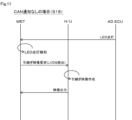
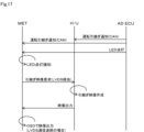
- FIG. 4 is a sequence diagram showing processing among the operation control ECU, H/U, and meter ECU when there is CAN communication;
- the functional block diagram showing the configuration of the vehicle notification system is a diagram showing a state in which the first power supply is lost, The same functional block diagram is a diagram showing a state in which the second power supply is lost,
- the functional block diagram showing the configuration of the vehicle notification system is a diagram showing a state in which the first power supply is lost, The same functional block diagram is a diagram showing a state in which the second power supply is lost,
- the sixth embodiment is a diagram showing a variation of functional arrangement in the meter ECU and H/U, Sequence diagram showing processing among the operation control ECU, H/U, and meter ECU with CAN communication
- it is a diagram showing a variation of functional arrangement in the meter ECU and H/U, FIG.
- FIG. 4 is a sequence diagram showing processing among the operation control ECU, H/U, and meter ECU when there is CAN communication;
- it is a diagram showing a variation of functional arrangement in the meter ECU and H/U
- FIG. 4 is a sequence diagram showing processing between an operation control ECU and a meter ECU with CAN communication
- FIG. 13 is a diagram showing each notification mode of sixth to eighth embodiments
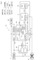
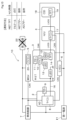
- the vehicle notification system 1 of this embodiment includes an operation control ECU 2, a meter ECU 3, an H/U (Head Unit) 4, a camera ECU 5 and a central ECU (C-ECU) 6.
- the operation control ECU 2 is an ECU that controls automatic operation of the vehicle via the vehicle control unit 7 and includes a microcomputer 8 and a buzzer 9 . Buzzer 9 is driven by microcomputer 8 .
- the meter ECU 3 is an ECU that controls the meter display, etc. of the instrument panel of the vehicle, and includes a microcomputer 10, a buzzer 11, an LED (Light Emission Display) 12, an OSD 13, a TFT 14, and the like. Buzzer 11 and LED 12 are driven by microcomputer 10 .
- the TFT 14 is a TFT (Thin Film Transistor) liquid crystal display, and the drawing display of the TFT 14 is controlled by the microcomputer 10 via the OSD 13 .
- An OSD (On Screen Display) 13 is a control IC for the TFT 14 .
- the meter ECU 3 has an LED 15 corresponding to a lighting display section, and the LED 15 is driven by the operation control ECU 2 via a direct wiring 16 .
- the LED 15 is turned on when the operation control ECU 2 determines that the driver should take over the main responsibility for driving the vehicle from the state in which the vehicle is being automatically driven.
- the LED 15 lights up when the anode side is driven to a high level.
- the microcomputer 10 of the meter ECU 3 detects that the operation control ECU 2 has turned on the LED 15 by referring to the potential of the anode of the LED 15 .
- the H/U 4 uses the microcomputer 17 to control the drawing display of the TFT 19 provided in the center display (CID) 18 .
- the microcomputer 17 also directly controls the drawing display of the TFT 14 provided in the meter ECU 3. At that time, it is possible to display rich content with a larger amount of information than the drawing display by the OSD 13.
- Communication between the H/U 4, the meter ECU 3 and the center display 18 is performed by LVDS (Low Voltage Differential Signaling).
- LVDS Low Voltage Differential Signaling
- the camera ECU 5 is an ECU that controls, by the microcomputer 20, a camera that captures images around the vehicle so that the operation control ECU 2 can automatically drive the vehicle.
- the camera ECU 5 communicates with the operation control ECU 2 and the vehicle control unit 7 by CAN (registered trademark).
- the C-ECU 6 communicates with the operation control ECU 2, the meter ECU 3 and the H/U 4 by CAN, and controls these ECUs in an integrated manner.
- the operating power supply is divided into two systems and supplied to each of the above configurations.
- the first power supply 21 supplies power to the operation control ECU 2, the H/U 4, the C-ECU 6, and the vehicle control unit 7, and the second power supply 22 supplies power to the operation control ECU 2, the meter ECU 3, the camera ECU 5, and the vehicle control unit 7. is supplying power to That is, both the operation control ECU 2 and the vehicle control unit 7 are supplied with two power sources.
- the driving control ECU 2 is able to control the vehicle control unit 7 because power is also supplied from the second power supply 22, but determines that the main driving force should be handed over to the driver due to the loss of the first power supply 21. Therefore, the LED 15 of the meter ECU 3 is turned on.
- the microcomputer 10 of the meter ECU 3 performs drawing display on the TFT 14 via the OSD 13 to display that the vehicle side is notifying the driver to take over the subject of driving.
- the operation control ECU 2 may drive and sound the buzzer 9, and the meter ECU 3 may also sound the buzzer 11 to make duplicate notifications.
- "Tell tale” shown in the figure means notification by the LED 15, and "whistling" means ringing.
- the LED 12 may be turned on to notify the driver.
- the vehicle notification system 1 includes the operation control ECU 2 that controls the automatic operation of the vehicle, and the display control ECU 3 that controls the display of the meter on the instrument panel and the display of the TFT 14.
- the display control ECU 3 is provided with an LED 15 that notifies the driver in a lighting state, and the LED 15 is driven by the operation control ECU 2 .
- the display control ECU 3 detects that the LED 15 has been turned on, the display control ECU 3 notifies the driver by displaying on the TFT 14 .
- the display control ECU 3 can notify the driver by displaying on the TFT 14 triggered by the lighting of the LED 15 by the operation control ECU 2 . Therefore, the notification from the operation control ECU 2 can be easily understood by the driver not only by lighting the LED 15 but also by displaying the information on the TFT 14 .
- the microcomputer 8A maintains the level of the output port at the middle level while the LED 15 is turned off. Then, the microcomputer 10A of the meter ECU 3A can determine that the anode potential of the LED 15 is at the middle level.
- the operation control ECU 2, H/U 4 and C-ECU 6 cease to function. Therefore, the anode potential of the LED 15 changes from middle level to low level.
- the microcomputer 10A of the meter ECU 3A detects that the anode potential has changed to a low level, it displays a drawing on the TFT 14 via the OSD 13, and notifies the driver that the vehicle should take over the main part of driving. display. Moreover, at this time, the meter ECU 3A may sound the buzzer 11 to make redundant notifications.
- FIG. 4 when the second power supply 22 is lost, the situation is the same as the case shown in FIG.
- the operation control ECU 2 detects vehicle behavior from information collected from various sensors (S1). Then, it is determined whether or not it is necessary to hand over the driving to the driver (S2). If the transfer is not necessary, the vehicle is controlled by the vehicle control unit 7 (S3) and the process returns to step S1. On the other hand, if it is determined that the handover is necessary in step 2, the process of lighting the LED 15 (S4), the process of sounding the buzzer 9 (S5), and the process of notifying the C-ECU 6 and the meter ECU 3 of the occurrence of an abnormality by CAN communication (S6). ) and a process for controlling the vehicle (S7) are performed in parallel.
- the meter ECU 3 determines whether there is a notification of the occurrence of an abnormality by CAN communication (S11). If there is no notification, it is determined whether or not the LED 15 has been turned on by the operation control ECU 2 (S15), and if not, the process returns to step S11. If the LED 15 is turned on, it is determined whether or not the LVDS communication with the H/U 4 is interrupted (S16). ). If the LVDS communication is interrupted, the OSD 13 notifies the operation handover using the TFT 14 (S17). On the other hand, in step S11, if there is a notification of the occurrence of an abnormality by CAN communication, in steps S12 to S14, the same processing as in steps S16 to S18 is performed.
- step S14 the operation control ECU 2 sequentially notifies the H/U 4 and the meter ECU 3 of the operation takeover and lights the LED 15 .
- the meter ECU 3 detects the lighting of the LED 15, it requests the H/U 4 to display a video image for notification of takeover by LVDS communication. Note that this request may be triggered by a driving handover notification from the driving control ECU 2 .
- the H/U 4 creates video data for handover notification in response to the above request.
- the image creation here may also be triggered by the driving handover notification from the driving control ECU 2 .
- the produced image data is output to meter ECU3, and it is made to display on TFT14.
- step S18 shown in FIG. 11 the operation control ECU 2 lights the LED 15, and when the meter ECU 3 detects the lighting, it requests the H/U 4 to display a video for notification of takeover via LVDS communication. Subsequent processing is the same as that shown in FIG.
- the vehicle notification system 1C of 4th Embodiment shown in FIG.12 and FIG.13 changes the power supply with respect to meter ECU3 to the 2nd power supply 22, and is performed from the 1st power supply 21.
- FIG. In this case, in the case shown in FIG. 12 where the first power supply 21 is lost, compared to the case shown in FIG. 9 ring only.
- the operation control ECU 2 lights the LED 15 and sounds the buzzer 9, the meter ECU 3 sounds the buzzer 11, and the H/U 4 displays using the TFT 14.
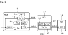
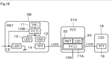
- FIGS. 16 and 17 show variations in the functional arrangement of the meter ECU and H/U.
- a microcomputer 17 is mounted on the H/U 31.
- FIG. 17 On the microcomputer 17, a plurality of OSs (Operating Systems) (not shown) are running in parallel via a virtual environment (hypervisor) not shown.
- one of the plurality of OSs is equipped with a meter 32, which is an application for controlling the display of the meter.
- Another OS is loaded with CID 33, which is an application that is displayed on CID 18 and mainly controls the display of infotainment-related functions.
- Information such as vehicle speed and telltale required for meter display control is input to the meter ECU 3 via CAN communication and processed by the microcomputer 10 . After that, information for drawing and displaying on the TFT 14 is transmitted from the microcomputer 10 to the H/U 21 by LVDS communication. H/U31 will transmit to meter ECU3 by LVDS communication, if video data is produced based on the information.
- meter ECU3 controls the display of TFT14 via OSD13.
- the microcomputer 10B of meter ECU3B does not perform CAN communication.
- Information necessary for meter display control is input to the microcomputer 17A of the H/U 31A through CAN communication and processed by the microcomputer 17A. After that, when image data is created based on the input information, it is transmitted to the meter ECU 3B by LVDS communication.
- the operation control ECU 2 if the CAN communication is valid, the operation control ECU 2 notifies the H/U 31A of the handover of operation. Subsequent processing is the same as in FIG.
- meter ECU34 is not provided with OSD13.
- the H/U 35 has only the microcomputer 17 and the display 33 .
- Information necessary for meter display control is input to the microcomputer 17 of the H/U 35 via CAN communication and processed by the microcomputer 17 .
- the H/U 35 generates video data based on the input information, transmits it to the center display 18 by LVDS communication, and displays it by the TFT 19 .
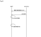
- the driving handover notification is performed between the vehicle control ECU 2 and the meter ECU 34.
- the vehicle control ECU 2 notifies the meter ECU 34 of driving handover by CAN communication and turns on the LED 15, the meter ECU 34 detects the lighting and generates video data for driving handover notification.
- FIG. 22 summarizes each notification mode of the sixth to eighth embodiments.
- the power supply for operation to each component does not necessarily have to be divided into two systems.
- the lighting display section is not limited to the LED, and the drawing display section is not limited to the TFT.
- the H/U and camera ECU may be provided as required.
- the protocol used for communication between ECUs is not limited to CAN or LVDS, and any protocol that can be used for communication between ECUs may be used.
Landscapes
- Engineering & Computer Science (AREA)
- Transportation (AREA)
- Mechanical Engineering (AREA)
- Chemical & Material Sciences (AREA)
- Combustion & Propulsion (AREA)
- Automation & Control Theory (AREA)
- Human Computer Interaction (AREA)
- Instrument Panels (AREA)
- Control Of Driving Devices And Active Controlling Of Vehicle (AREA)
Priority Applications (1)
| Application Number | Priority Date | Filing Date | Title |
|---|---|---|---|
| US18/635,973 US20240343117A1 (en) | 2021-11-02 | 2024-04-15 | Vehicle notification system |
Applications Claiming Priority (2)
| Application Number | Priority Date | Filing Date | Title |
|---|---|---|---|
| JP2021179450A JP7793937B2 (ja) | 2021-11-02 | 2021-11-02 | 車両通知システム |
| JP2021-179450 | 2021-11-02 |
Related Child Applications (1)
| Application Number | Title | Priority Date | Filing Date |
|---|---|---|---|
| US18/635,973 Continuation US20240343117A1 (en) | 2021-11-02 | 2024-04-15 | Vehicle notification system |
Publications (1)
| Publication Number | Publication Date |
|---|---|
| WO2023079899A1 true WO2023079899A1 (ja) | 2023-05-11 |
Family
ID=86241297
Family Applications (1)
| Application Number | Title | Priority Date | Filing Date |
|---|---|---|---|
| PCT/JP2022/037442 Ceased WO2023079899A1 (ja) | 2021-11-02 | 2022-10-06 | 車両通知システム |
Country Status (3)
| Country | Link |
|---|---|
| US (1) | US20240343117A1 (https=) |
| JP (1) | JP7793937B2 (https=) |
| WO (1) | WO2023079899A1 (https=) |
Citations (5)
| Publication number | Priority date | Publication date | Assignee | Title |
|---|---|---|---|---|
| WO2015151243A1 (ja) * | 2014-04-02 | 2015-10-08 | 日産自動車株式会社 | 車両用情報呈示装置 |
| WO2018225225A1 (ja) * | 2017-06-08 | 2018-12-13 | 三菱電機株式会社 | 車両制御装置 |
| JP2019147535A (ja) * | 2018-02-28 | 2019-09-05 | 矢崎総業株式会社 | 自動運転時情報伝達方法、自動運転時情報伝達装置、および自動運転時情報伝達システム |
| JP2019172180A (ja) * | 2018-03-29 | 2019-10-10 | 矢崎総業株式会社 | 自動運転時情報伝達方法 |
| JP2020185864A (ja) * | 2019-05-14 | 2020-11-19 | トヨタ自動車株式会社 | 車両 |
-
2021
- 2021-11-02 JP JP2021179450A patent/JP7793937B2/ja active Active
-
2022
- 2022-10-06 WO PCT/JP2022/037442 patent/WO2023079899A1/ja not_active Ceased
-
2024
- 2024-04-15 US US18/635,973 patent/US20240343117A1/en active Pending
Patent Citations (5)
| Publication number | Priority date | Publication date | Assignee | Title |
|---|---|---|---|---|
| WO2015151243A1 (ja) * | 2014-04-02 | 2015-10-08 | 日産自動車株式会社 | 車両用情報呈示装置 |
| WO2018225225A1 (ja) * | 2017-06-08 | 2018-12-13 | 三菱電機株式会社 | 車両制御装置 |
| JP2019147535A (ja) * | 2018-02-28 | 2019-09-05 | 矢崎総業株式会社 | 自動運転時情報伝達方法、自動運転時情報伝達装置、および自動運転時情報伝達システム |
| JP2019172180A (ja) * | 2018-03-29 | 2019-10-10 | 矢崎総業株式会社 | 自動運転時情報伝達方法 |
| JP2020185864A (ja) * | 2019-05-14 | 2020-11-19 | トヨタ自動車株式会社 | 車両 |
Also Published As
| Publication number | Publication date |
|---|---|
| JP7793937B2 (ja) | 2026-01-06 |
| JP2023068389A (ja) | 2023-05-17 |
| US20240343117A1 (en) | 2024-10-17 |
Similar Documents
| Publication | Publication Date | Title |
|---|---|---|
| KR102532971B1 (ko) | 표시장치 및 이의 구동방법 | |
| US12062309B2 (en) | Device and method for detecting screen freeze error of display of vehicle | |
| US20160351129A1 (en) | Display device | |
| CN100470312C (zh) | 显示面板的驱动方法及其装置 | |
| US11069270B2 (en) | Control circuit, drive circuit, electro-optical device, electronic apparatus including electro-optical device, movable body including electronic apparatus, and error detection method | |
| JP2005222018A (ja) | 液晶表示装置の駆動回路 | |
| WO2020184088A1 (ja) | 表示制御装置、表示装置、表示制御システム及び信頼性判定プログラム | |
| US12300188B2 (en) | Backlight device, transport device including backlight device, and control method thereof | |
| US20230237977A1 (en) | Device and method for driving a display panel | |
| WO2023079899A1 (ja) | 車両通知システム | |
| US11056033B2 (en) | Electro-optical apparatus, display control system, display driver, electronic device, and mobile unit | |
| JP2021128257A (ja) | 表示装置 | |
| CN109493815B (zh) | 显示装置以及背光驱动方法 | |
| JP2024099587A (ja) | 表示制御装置、表示制御システム及び表示制御プログラム | |
| JP2008096660A (ja) | 表示装置 | |
| TWI707792B (zh) | 用於車輛故障顯示器的功能安全系統以及相關的功能故障系統 | |
| WO2022185822A1 (ja) | 車両用表示制御システム | |
| JP2008203768A (ja) | 表示装置 | |
| WO2021117640A1 (ja) | タイミングコントローラおよびディスプレイシステム、自動車 | |
| US11074843B2 (en) | Drive circuit, electro-optical device, electronic apparatus including electro-optical device, and movable body including electronic apparatus | |
| JP2026042468A (ja) | 表示制御装置、表示制御方法及びコンピュータプログラム | |
| WO2024128094A1 (ja) | 表示制御装置、それを用いた自動車、表示システム | |
| JP2024148829A (ja) | 車両用表示装置 | |
| US20210405947A1 (en) | Display control apparatus, display apparatus, display control system, and storage medium | |
| CN121410978A (zh) | 一种显示控制装置、方法以及计算机存储介质 |
Legal Events
| Date | Code | Title | Description |
|---|---|---|---|
| 121 | Ep: the epo has been informed by wipo that ep was designated in this application |
Ref document number: 22889723 Country of ref document: EP Kind code of ref document: A1 |
|
| NENP | Non-entry into the national phase |
Ref country code: DE |
|
| 122 | Ep: pct application non-entry in european phase |
Ref document number: 22889723 Country of ref document: EP Kind code of ref document: A1 |