WO2023079870A1 - サーボ再生装置、サーボ再生ヘッド、再生ヘッド及び磁気テープの製造方法 - Google Patents
サーボ再生装置、サーボ再生ヘッド、再生ヘッド及び磁気テープの製造方法 Download PDFInfo
- Publication number
- WO2023079870A1 WO2023079870A1 PCT/JP2022/036636 JP2022036636W WO2023079870A1 WO 2023079870 A1 WO2023079870 A1 WO 2023079870A1 JP 2022036636 W JP2022036636 W JP 2022036636W WO 2023079870 A1 WO2023079870 A1 WO 2023079870A1
- Authority
- WO
- WIPO (PCT)
- Prior art keywords
- servo
- reproducing
- read
- magnetic tape
- bands
- Prior art date
- Legal status (The legal status is an assumption and is not a legal conclusion. Google has not performed a legal analysis and makes no representation as to the accuracy of the status listed.)
- Ceased
Links
Images





Classifications
-
- G—PHYSICS
- G11—INFORMATION STORAGE
- G11B—INFORMATION STORAGE BASED ON RELATIVE MOVEMENT BETWEEN RECORD CARRIER AND TRANSDUCER
- G11B5/00—Recording by magnetisation or demagnetisation of a record carrier; Reproducing by magnetic means; Record carriers therefor
- G11B5/48—Disposition or mounting of heads or head supports relative to record carriers ; arrangements of heads, e.g. for scanning the record carrier to increase the relative speed
- G11B5/54—Disposition or mounting of heads or head supports relative to record carriers ; arrangements of heads, e.g. for scanning the record carrier to increase the relative speed with provision for moving the head into or out of its operative position or across tracks
- G11B5/55—Track change, selection or acquisition by displacement of the head
- G11B5/5504—Track change, selection or acquisition by displacement of the head across tape tracks
-
- G—PHYSICS
- G11—INFORMATION STORAGE
- G11B—INFORMATION STORAGE BASED ON RELATIVE MOVEMENT BETWEEN RECORD CARRIER AND TRANSDUCER
- G11B20/00—Signal processing not specific to the method of recording or reproducing; Circuits therefor
- G11B20/10—Digital recording or reproducing
-
- G—PHYSICS
- G11—INFORMATION STORAGE
- G11B—INFORMATION STORAGE BASED ON RELATIVE MOVEMENT BETWEEN RECORD CARRIER AND TRANSDUCER
- G11B21/00—Head arrangements not specific to the method of recording or reproducing
- G11B21/02—Driving or moving of heads
- G11B21/10—Track finding or aligning by moving the head ; Provisions for maintaining alignment of the head relative to the track during transducing operation, i.e. track following
-
- G—PHYSICS
- G11—INFORMATION STORAGE
- G11B—INFORMATION STORAGE BASED ON RELATIVE MOVEMENT BETWEEN RECORD CARRIER AND TRANSDUCER
- G11B23/00—Record carriers not specific to the method of recording or reproducing; Accessories, e.g. containers, specially adapted for co-operation with the recording or reproducing apparatus ; Intermediate mediums; Apparatus or processes specially adapted for their manufacture
- G11B23/02—Containers; Storing means both adapted to cooperate with the recording or reproducing means
- G11B23/03—Containers for flat record carriers
- G11B23/033—Containers for flat record carriers for flexible discs
-
- G—PHYSICS
- G11—INFORMATION STORAGE
- G11B—INFORMATION STORAGE BASED ON RELATIVE MOVEMENT BETWEEN RECORD CARRIER AND TRANSDUCER
- G11B23/00—Record carriers not specific to the method of recording or reproducing; Accessories, e.g. containers, specially adapted for co-operation with the recording or reproducing apparatus ; Intermediate mediums; Apparatus or processes specially adapted for their manufacture
- G11B23/02—Containers; Storing means both adapted to cooperate with the recording or reproducing means
- G11B23/113—Apparatus or processes specially adapted for the manufacture of magazines or cassettes, e.g. initial loading into container
-
- G—PHYSICS
- G11—INFORMATION STORAGE
- G11B—INFORMATION STORAGE BASED ON RELATIVE MOVEMENT BETWEEN RECORD CARRIER AND TRANSDUCER
- G11B5/00—Recording by magnetisation or demagnetisation of a record carrier; Reproducing by magnetic means; Record carriers therefor
- G11B5/008—Recording on, or reproducing or erasing from, magnetic tapes, sheets, e.g. cards, or wires
- G11B5/00813—Recording on, or reproducing or erasing from, magnetic tapes, sheets, e.g. cards, or wires magnetic tapes
- G11B5/00817—Recording on, or reproducing or erasing from, magnetic tapes, sheets, e.g. cards, or wires magnetic tapes on longitudinal tracks only, e.g. for serpentine format recording
- G11B5/00821—Recording on, or reproducing or erasing from, magnetic tapes, sheets, e.g. cards, or wires magnetic tapes on longitudinal tracks only, e.g. for serpentine format recording using stationary heads
- G11B5/00826—Recording on, or reproducing or erasing from, magnetic tapes, sheets, e.g. cards, or wires magnetic tapes on longitudinal tracks only, e.g. for serpentine format recording using stationary heads comprising a plurality of single poles or gaps or groups thereof operative at the same time
-
- G—PHYSICS
- G11—INFORMATION STORAGE
- G11B—INFORMATION STORAGE BASED ON RELATIVE MOVEMENT BETWEEN RECORD CARRIER AND TRANSDUCER
- G11B5/00—Recording by magnetisation or demagnetisation of a record carrier; Reproducing by magnetic means; Record carriers therefor
- G11B5/48—Disposition or mounting of heads or head supports relative to record carriers ; arrangements of heads, e.g. for scanning the record carrier to increase the relative speed
- G11B5/58—Disposition or mounting of heads or head supports relative to record carriers ; arrangements of heads, e.g. for scanning the record carrier to increase the relative speed with provision for moving the head for the purpose of maintaining alignment of the head relative to the record carrier during transducing operation, e.g. to compensate for surface irregularities of the latter or for track following
- G11B5/584—Disposition or mounting of heads or head supports relative to record carriers ; arrangements of heads, e.g. for scanning the record carrier to increase the relative speed with provision for moving the head for the purpose of maintaining alignment of the head relative to the record carrier during transducing operation, e.g. to compensate for surface irregularities of the latter or for track following for track following on tapes
Definitions
- This technology relates to technology such as a servo reproducing device that reads and reproduces a servo pattern recorded on a magnetic tape.
- a magnetic tape is provided with a plurality of data bands on which data is recorded and a plurality of servo bands on which servo patterns are recorded.
- a servo pattern is recorded on a servo band by a servo write head of a servo recording/reproducing device (see, for example, Japanese Unexamined Patent Application Publication No. 2002-100003).
- the servo pattern recorded in the servo band is read and reproduced by the servo reproducing head of the servo recording/reproducing device.
- Information of the reproduced servo pattern is used as information for confirming whether the servo pattern has been correctly recorded.
- the purpose of the present technology is to provide a technology that enables the servo pattern to be accurately read by the servo reproducing head even when the pitch between the servo bands is narrow.
- the servo reproducing device has a servo reproducing head.
- the servo read head has a first read head section and a second read head section.
- the first reproducing head section reads servo patterns recorded in a plurality of first servo bands, which are part of the plurality of servo bands on a magnetic tape having a plurality of servo bands.
- the second reproducing head section reads servo patterns recorded in a plurality of second servo bands which are part of other servo bands.
- reading of the servo pattern can be shared by two or more reproducing head units for each servo band group. Therefore, for example, even if the number of servo bands is increased and the pitch of the servo bands is narrowed for high density recording of data, the servo patterns in all the servo bands can be read accurately.
- the first reproducing head section when numbers are sequentially assigned to the plurality of servo bands in the width direction of the magnetic tape, the first reproducing head section is assigned a first number skipping at least one. Servo patterns recorded in the plurality of first servo bands corresponding to numbers (eg, even numbers) may be read.
- the second reproducing head section includes the plurality of second servos corresponding to second numbers (for example, odd numbers) that are skipped by at least one number and that are different from the first numbers.
- second numbers for example, odd numbers
- a servo pattern recorded in the band may be read.
- the plurality of servo bands are arranged at a first pitch in the width direction of the magnetic tape, and the first reproducing head section and the second reproducing head section extend across the width of the magnetic tape.
- the first read head portion and the second read head portion are servo elements for reading the servo pattern, and the length direction of each read head portion is oriented in the first read head portion.
- the first reproducing head portion and the second reproducing head portion have a length direction in the width direction of the magnetic tape, and the first reproducing head portion and the second reproducing head portion
- the head units may be arranged such that their positions in the length direction of each read head unit are staggered.
- the first reproducing head portion and the second reproducing head portion have a width direction in the length direction of the magnetic tape, and the first reproducing head portion and the second reproducing head portion
- the head section has a first region corresponding to the position where the servo element is provided in the length direction of each read head section, and a position where the servo element is not provided in the length direction of each read head section. and a second area facing the magnetic tape, wherein the width of each reproducing head portion in the second area in the width direction is larger than the width of the first area in the facing surface. is also narrowed, or Alternatively, a plurality of grooves may be formed in the second region on the facing surface along the width direction of each read head portion and aligned in the length direction of each read head portion.
- the plurality of servo bands may be arranged at a first pitch in the width direction of the magnetic tape, and the first pitch may be 1280 ⁇ m or less.
- the magnetic tape may have a width of 12.656 mm or less in the width direction of the magnetic tape.
- the magnetic tape may have 9 or more servo bands.
- each of the plurality of servo bands may have a width of 93 ⁇ m or less in the width direction of the magnetic tape.
- the first reproducing head section and the second reproducing head section have a length direction in the width direction of the magnetic tape, and the first reproducing head section and the second reproducing head section
- the sections may be 19.3 mm or more in length along the length of each read head section.
- the first reproducing head section and the second reproducing head section may be of an inductive type.
- the servo pattern includes a first servo pattern inclined at a first azimuth angle with respect to the width direction of the magnetic tape and a first azimuth angle with respect to the width direction of the magnetic tape. and a second servo pattern inclined at a second azimuth angle in the opposite direction.
- the first reproducing head section and the second reproducing head section read the servo pattern at both ends of the first servo pattern and the second servo pattern excluding the central portion.
- the first reproducing head section includes the first reproducing head section for reading the first servo pattern and the second reproducing head section for reading the second servo pattern in the plurality of first servo bands.
- the second reproducing head section includes the third reproducing head for reading the first servo pattern and the second servo pattern in the plurality of second servo bands. and a fourth read head for reading the .
- the first reproducing head section and the second reproducing head section have a width direction in the length direction of the magnetic tape, and the two reproducing heads of the first reproducing head section , may be adjacent to each other in the width direction of each read head portion, and the two read heads of the second read head portion may be adjacent to each other in the width direction of each read head portion.
- the first reproducing head portion and the second reproducing head portion have a width direction in the length direction of the magnetic tape, and the first reproducing head portion and the second reproducing head portion
- the two read heads of at least one read head portion of the head portions may not be adjacent to each other in the width direction of each read head portion.
- a servo read head includes a first read head section and a second read head section.
- the first reproducing head section reads servo patterns recorded in a plurality of first servo bands, which are part of the plurality of servo bands on a magnetic tape having a plurality of servo bands.
- the second reproducing head section reads servo patterns recorded in a plurality of second servo bands which are part of other servo bands.
- a reproducing head is a reproducing head having a plurality of servo elements that respectively read servo patterns recorded in the plurality of servo bands on a magnetic tape having a plurality of servo bands, wherein the reproducing head includes the magnetic It has a length direction in the width direction of the tape and a width direction in the length direction of the magnetic tape, and the read head is located at a position where the servo element is provided in the length direction of the read head.
- a facing surface facing the magnetic tape including corresponding first regions and second regions corresponding to positions where the servo elements are not provided in the length direction of the reproducing head;
- the width of the second region in the width direction of the read head is narrower than the width of the first region in the first direction, or the second region is the width of the facing surface.
- a plurality of grooves are formed along the width direction of the read head and aligned in the length direction of the read head.
- a magnetic tape manufacturing method reads a servo pattern recorded in a plurality of first servo bands, which are a part of the plurality of servo bands in a magnetic tape having a plurality of servo bands.
- the servo pattern is read by a servo reproducing head having one reproducing head portion and a second reproducing head portion for reading the servo patterns recorded in a plurality of second servo bands which are part of the other servo bands. , based on the read information of the servo pattern, confirm whether the servo pattern has been written correctly.
- FIG. 3 is a schematic diagram of the magnetic tape as viewed from the side;
- FIG. 2 is a plan view showing the relationship between a servo reproducing head and a servo band, viewed from the side of the servo reproducing head facing the magnetic tape;
- FIG. FIG. 3 is a perspective view of the servo reproducing head viewed from the side facing the magnetic tape; It is a figure showing each example concerning this art and each comparative example.
- FIG. 10 is a plan view showing the relationship between a servo reproducing head and servo bands according to a comparative example, viewed from the side of the servo reproducing head facing the magnetic tape;
- FIG. 10 is a perspective view of a servo reproducing head according to a comparative example, viewed from the side facing the magnetic tape;
- FIG. 11 is a plan view showing the relationship between a servo reproducing head and a servo band according to still another comparative example, viewed from the side of the servo reproducing head facing the magnetic tape;
- FIG. 11 is a perspective view of a servo reproducing head according to still another comparative example, viewed from the side facing the magnetic tape;
- FIG. 10 is a diagram showing a form in which the servo pattern can be read and a form in which the servo pattern cannot be read in the central portion of the servo element; It is a figure which shows an example of the surface low-friction processing in an opposing surface.
- FIG. 11 is a perspective view of a servo reproducing head according to a seventh embodiment, viewed from the side facing the magnetic tape;
- FIG. 1 is a schematic diagram of the magnetic tape 1 viewed from the side
- FIG. 2 is a schematic diagram of the magnetic tape 1 viewed from above.
- the magnetic tape 1 is long in the length direction (X-axis direction), short in the width direction (Y-axis direction), and thin in the thickness direction (Z-axis direction). It is
- the magnetic tape 1 includes a tape-shaped substrate 2 elongated in the length direction (X-axis direction), a non-magnetic layer 3 provided on one main surface of the substrate 2, and a non-magnetic layer 3 provided on the non-magnetic layer 3. and a back layer 5 provided on the other main surface of the substrate 2 .
- the back layer 5 may be provided as required, and the back layer 5 may be omitted.
- the base material 2 is a nonmagnetic support that supports the nonmagnetic layer 3 and the magnetic layer 4 .
- the base material 2 includes, for example, at least one of polyesters, polyolefins, cellulose derivatives, vinyl resins, and other polymer resins.
- the magnetic layer 4 is a recording layer for recording data.
- the magnetic layer 4 is formed on the non-magnetic layer 3 or the substrate 2 by coating, sputtering, or the like, for example.
- the magnetic layer 4 may contain magnetic powder, binder, conductive particles, and the like.
- the magnetic layer 4 may further contain additives such as lubricants, abrasives, and antirust agents, if necessary.
- the magnetic layer 4 may be vertically oriented or may be longitudinally oriented.
- the magnetic powder contained in the magnetic layer 4 includes, for example, nanoparticles containing ⁇ -iron oxide ( ⁇ -iron oxide particles), nanoparticles containing hexagonal ferrite (hexagonal ferrite particles), and nanoparticles containing Co-containing spinel ferrite. It is composed of particles (cobalt ferrite) or the like.
- the non-magnetic layer 3 may contain non-magnetic powder and a binder.
- the non-magnetic layer 3 may contain additives such as electrically conductive particles, lubricants, curing agents, and rust preventives, if necessary.
- the non-magnetic layer 3 can be omitted (for example, when the magnetic layer 4 is formed on the substrate 3 by sputtering).
- the back layer 5 contains non-magnetic powder and a binder.
- the back layer 5 may contain additives such as a lubricant, a curing agent and an antistatic agent, if necessary.
- the width (Y-axis direction) of the magnetic tape 1 is, for example, 12.656 mm (approximately 1/2 inch) or less.
- the width of the magnetic tape 1 may be 25.4 mm (1 inch) or less, and the size can be changed as appropriate.
- the magnetic layer 4 has a plurality of data bands (data bands #0 to #7), a plurality of servo bands (servo bands #0 to #8), and two guard bands. are doing.
- a data band is an area in which data is written (an area including a plurality of recording tracks), and a servo band is an area in which a predetermined servo pattern is written.
- the guard bands are blank areas provided at both ends of the magnetic tape 1 in the width direction.
- the data band, servo band, and guard band each have a shape that is long in the length direction (X-axis direction) and short in the width direction (Y-axis direction), and are aligned in the width direction. Also, the servo bands are arranged at positions sandwiching each data band in the width direction (Y-axis direction).
- the number of data bands is, for example, eight or more, and the number of servo bands is, for example, nine or more.
- the number of data bands and the number of servo bands are not limited to these, and can be changed as appropriate.
- the width of the servo band (in the Y-axis direction) is, for example, 93 ⁇ m, 70 ⁇ m or less.
- the pitch of each servo band in the width direction (Y-axis direction) of the magnetic tape 1 is, for example, 1280 ⁇ m or less.
- the width of the servo band and the pitch of each servo band are not limited to this and can be changed as appropriate.
- the servo pattern recorded in the servo band includes a first servo pattern ("/") inclined at a first azimuth angle with respect to the width direction (Y-axis direction), and a first servo pattern ("/") inclined at a first azimuth angle and a second servo pattern (" ⁇ ") slanted at a second azimuth angle in the opposite direction.
- FIG. 3 is a diagram showing a servo recording/reproducing device 100 according to the first embodiment of the present technology.
- the servo recording/reproducing apparatus 100 (servo reproducing apparatus) includes a feed roller 11, a demagnetizing section 12, a servo write head 15, a servo reproducing head 20, a winding roller 16, and four pairs of capstan rollers 17. It has
- the delivery roller 11 is capable of rotatably supporting the roll-shaped magnetic tape 1.
- the delivery roller 11 is rotated in accordance with the driving of a motor or the like, and delivers the magnetic tape 1 toward the downstream side according to the rotation.
- the take-up roller 16 can rotatably support the rolled magnetic tape 1 .
- the take-up roller 16 rotates in accordance with the driving of a motor or the like, and takes up the magnetic tape 1 in accordance with the rotation.
- the four pairs of capstan rollers 17 are capable of sandwiching the magnetic tape 1 from both sides in the vertical direction.
- the four pairs of capstan rollers 17 are rotated by driving a motor or the like, and convey the magnetic tape 1 along the conveying path according to the rotation.
- the feed roller 11, take-up roller 16 and four pairs of capstan rollers 17 are capable of transporting the magnetic tape 1 at a constant speed within the transport path.
- the servo write head 15 is arranged, for example, above the magnetic tape 1 (on the side of the magnetic layer 4).
- the servo write head 15 applies a magnetic field to the servo band at a predetermined timing according to the rectangular wave pulse signal, and records a servo pattern on the servo band.
- the servo write head 15 is capable of recording servo patterns for all the servo bands (#0 to #8) when the magnetic tape 1 passes under the servo write head 15. .
- the demagnetizing unit 12 is arranged, for example, on the upstream side of the servo write head 15 and below the magnetic tape 1 (on the base material 2 side).
- the demagnetizing section 12 is composed of, for example, two permanent magnets 13 and 14 . Before the servo pattern is recorded by the servo write head 15, the permanent magnets 13 and 14 apply a magnetic field to the entire magnetic layer 4 by a DC magnetic field to demagnetize the entire magnetic layer 4.
- the servo reproducing head 20 is arranged downstream of the servo write head 15 and above the magnetic tape 1 (magnetic layer 4 side).
- the servo reproducing head 20 is configured to read the magnetic field generated from the servo pattern recorded on the magnetic tape 1 so as to reproduce the information of the servo pattern.
- the servo reproducing head 20 can read servo patterns from all the servo bands (#0 to #8) when the magnetic tape 1 passes under the servo reproducing head 20.
- the information of the servo pattern read by the servo reproducing head 20 is transmitted to a control section which will be described later.
- the control unit checks whether the servo pattern has been accurately recorded.
- the type of the servo reproducing head 20 is, for example, an inductive type, an MR type (Magneto Resistive), a GMR type (Giant Magneto Resistive), a TMR type (Tunnel Magneto Resistive), or the like. The details of the configuration of the servo reproducing head 20 will be described later.
- the servo recording/reproducing device 100 includes a control device that controls each part of the servo recording/reproducing device 100 in an integrated manner.
- a control device includes, for example, a control unit, a storage unit, a communication unit, and the like.
- the control section is composed of, for example, a CPU (Central Processing Unit) or the like, and comprehensively controls each section of the servo recording/reproducing apparatus 100 according to a program stored in the storage section.
- CPU Central Processing Unit
- the storage unit includes a non-volatile memory in which various data and various programs are recorded, and a volatile memory used as a work area for the control unit.
- the various programs described above may be read from a portable recording medium such as an optical disk or a semiconductor memory, or may be downloaded from a server device on a network.
- the communication unit is configured to be able to communicate with another device such as a server device, for example.
- FIG. 4 is a plan view showing the relationship between the servo reproducing head 20 and the servo band, viewed from the side of the servo reproducing head 20 facing the magnetic tape 1.
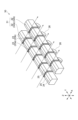
- FIG. 5 is a perspective view of the servo reproducing head 20 viewed from the side facing the magnetic tape.
- the servo reproducing head 20 has a first reproducing head section 21a and a second reproducing head section 21b. Note that the number of reproduction head units 21 may be three or more.
- the magnetic tape 1 flows from left to right. Therefore, in this example, the first reproducing head portion 21a is arranged on the upstream side in the conveying direction of the magnetic tape 1, and the second reproducing head portion 21b is arranged on the downstream side in the conveying direction of the magnetic tape 1. It is
- the first reproducing head unit 21a is configured to read a plurality of first servo bands (#0, #2, #4, #4, #6, #8) can be read.
- the first reproducing head unit 21a assigns first numbers (# 0, #2, #4, #6, and #8), the servo patterns recorded in the plurality of first servo bands (#0, #2, #4, #6, and #8) can be read. It is possible.
- the second reproducing head section 21b selects a plurality of second servo bands (#1, #3, #5, #5, #7) is configured to be able to read the servo pattern recorded.
- the second reproducing head section 21b corresponds to second numbers (#1, #3, #5, #7) that are skipped by one and different from the first numbers. It is possible to read servo patterns recorded in a plurality of second servo bands (#1, #3, #5, #7).
- the first read head section 21a and the second read head section 21b can jointly read servo patterns on all servo bands (#0 to #8).
- the first read head section 21a and the second read head section 21b have the same configuration, and the first read head section 21a and the second read head section 21b are arranged in the longitudinal direction ( Y-axis direction) are shifted.
- the number of reproduction head units 21 is two. Accordingly, the first reproducing head section 21a and the second reproducing head section 21b are each configured to read servo patterns in a plurality of servo bands corresponding to numbers skipped by one.
- each read head unit 21 may be configured to read servo patterns in a plurality of servo bands corresponding to numbers that are skipped by two.
- each reproducing head unit 21 may be configured to be able to read servo patterns recorded in a plurality of servo bands corresponding to numbers skipped by at least one. It changes according to the number of reproduction head units 21 .
- the first playback head section 21a includes a first playback head 22a and a second playback head 22b. Also, the second reproducing head section 21b includes a third reproducing head 22c and a fourth reproducing head 22d. 4 and 5, the upstream side in the transport direction of the magnetic tape 1 is the left side. , the second reproducing head 22b, the third reproducing head 22c, and the fourth reproducing head 22d.
- Each of the four read heads 22 has a columnar shape that is long in the length direction (Y-axis direction), short in the width direction (X-axis direction), and short in the vertical direction (Z-axis direction).
- the length (Y-axis direction) of each reproducing head 22 is, for example, 19.3 mm or longer. Note that the length of the reproducing head 22 can be changed as appropriate.
- the length of the reproducing head 22 is such that both ends of the reproducing head 22 in the length direction are wider than the width of the magnetic tape 1 even when the reproducing heads 22 are arranged to be shifted in the length direction. It is located on the outside with a sufficient margin and has a length that does not affect the running of the magnetic tape 1 .
- the length direction (Y-axis direction) of the reproducing head 22 corresponds to the width direction of the magnetic tape 1
- the width direction (X-axis direction) of the reproducing head 22 corresponds to the width direction of the magnetic tape 1
- the vertical direction of the reproducing head 22 corresponds to the thickness direction of the magnetic tape 1
- the direction of the magnetic tape 1 is the direction when the magnetic tape 1 passes the position of the servo reproducing head 20 .
- a facing surface 24 facing the magnetic tape 1 is provided along the length direction (Y-axis direction).
- two tapered surfaces 25 inclined in opposing directions with respect to the horizontal plane are provided at positions sandwiching the opposing surface 24 in the width direction (X-axis direction) in the lower portion of the read head 22 .
- the first reproducing head 22a in the first reproducing head section 21a outputs first servo patterns in five servo bands (#0, #2, #4, #6, and #8) (first servo band). ("/") can be read.
- the second reproducing head 22b in the first reproducing head section 21a is the second reproducing head in the five servo bands (#0, #2, #4, #6, #8) (first servo band). It is possible to read a servo pattern (" ⁇ ").
- the third reproducing head 22c in the second reproducing head section 21b outputs the first servo patterns ( "/") can be read. Also, the fourth reproducing head 22d in the second reproducing head section 21b outputs the second servo patterns ( " ⁇ ") can be read.
- the first reproducing head 22a has five first servo elements 23a (gaps) capable of reading the first servo pattern ("/").
- the first servo element 23a is inclined at the first azimuth angle with respect to the length direction (Y-axis direction), like the first servo pattern.
- the second reproducing head 22b has five second servo elements 23b (gaps) capable of reading the second servo pattern (" ⁇ ").
- the second servo element 23b is formed to be inclined at the second azimuth angle with respect to the length direction (Y-axis direction).
- the third reproducing head 22c has five first servo elements 23a (gaps) capable of reading the first servo pattern ("/").
- the fourth read head 22d has five second servo elements 23b (gaps) capable of reading the second servo pattern (" ⁇ ").
- the first reproducing head 22a and the third reproducing head 22c have the same configuration.
- the second reproducing head 22b and the fourth reproducing head 22d have the same configuration.
- the first reproducing head 22a and the second reproducing head 22b (the first reproducing head section 21a) and the third reproducing head 22c and the fourth reproducing head 22d (the second reproducing head section 21b) are , are staggered in the length direction (Y-axis direction). This shift amount is a distance corresponding to the pitch (Y-axis direction) between adjacent servo bands.
- the servo element 23 is provided on the facing surface 24 of each reproducing head 22 .
- the servo elements 23 are arranged at a pitch (second pitch) that is twice the pitch (first pitch) between the servo bands in the length direction (Y-axis direction).
- the pitch between the servo elements 23 is twice the pitch between the servo bands.
- the pitch between the servo elements 23 is typically three times the pitch between the servo bands.
- the pitch between the servo elements 23 should be an integral multiple of the pitch between the servo bands and at least twice the pitch between the servo bands. It changes according to the number of the head parts 21. FIG.
- each reproducing head 22 five signal reading sections 26 corresponding to the five servo elements 23 are provided on its upper portion (on the side opposite to the side on which the servo elements 23 are provided).
- the signal reading unit 26 is a mechanism for causing the corresponding servo element 23 to read the servo pattern and reading the signal. If the servo reproducing head 20 is of the inductive type, the signal reading section 26 is composed of a coil.
- the number of servo elements 23 is five, but the number of servo elements 23 can be changed as appropriate. If the number of servo elements 23 is too large, the pitch (in the Y-axis direction) of the servo elements 23 becomes too narrow, and there is a possibility that the servo pattern cannot be properly read. The number is set in consideration of this point.
- the third reproducing head 22c and the fourth reproducing head 22d each have five servo elements 23.
- One servo element 23 provided on one end side of the elements 23 is not used. Therefore, this one servo element 23 can be omitted.
- the cost can be reduced by using heads having the same configuration for the first read head section 21a and the second read head section 21b.
- the four read heads 22 are attached to a position adjustment mechanism (not shown) to which these four read heads 22 can be attached.
- This position adjustment mechanism can integrally move the four reproducing heads 22 in the vertical direction (Z-axis direction), the length direction (Y-axis direction), and the width direction (X-axis direction). can be moved to The adjustment of the amount of deviation in the length direction (Y-axis direction) of the four reproducing heads 22 is performed by movement in the Y-axis direction by this position adjustment mechanism.
- FIG. 6 is a diagram showing each example and each comparative example.
- FIG. 7 is a plan view showing the relationship between the servo reproducing head 30 and the servo band according to the comparative example, viewed from the side of the servo reproducing head 30 facing the magnetic tape 1.
- FIG. 8 is a perspective view of the servo reproducing head 30 according to the comparative example, viewed from the side facing the magnetic tape.
- FIG. 9 is a plan view showing the relationship between the servo reproducing head 40 and the servo band according to still another comparative example, viewed from the side of the servo reproducing head 40 facing the magnetic tape 1.
- FIG. FIG. 10 is a perspective view of a servo reproducing head 40 according to still another comparative example, viewed from the side facing the magnetic tape.
- Comparative example (1) corresponds to the first comparative example in FIG.
- the servo reproducing head 30 reproduces the servo patterns written in the five servo bands of the magnetic tape 1 having five servo bands in total. It is configured to be read by one read head unit 31 (two read heads 32).
- the servo reproducing head 40 reproduces the servos written in the nine servo bands for the magnetic tape 1 having a total of nine servo bands.
- the pattern is read by one reproducing head unit 41 (two reproducing heads 42).
- the read head section 31 in the servo read head 30 according to Comparative Example (1) includes a first read head 32a and a second read head 32b.
- the read head section 41 in the servo read head 40 according to Comparative Example (2) includes a first read head 42a and a second read head 42b.
- each reproducing head 32 has five servo elements 23 (the number corresponding to the servo band).
- the number of servo elements 23 is nine (the number corresponding to the number of servo bands) in each reproducing head 42 .
- the pitch of each servo element 23 in the length direction (Y-axis direction) of the read head 22 is equal to the pitch of the servo band.
- the playback heads 22 according to the present embodiment and the playback heads 32 and 42 according to the comparative example have the same basic configuration. However, in this embodiment, two or more read head units 21 are used, the two or more read head units 21 share the servo band to be in charge (at least one servo band is skipped), This example differs from the comparative example in that the pitch of the servo elements 23 is set to be an integral multiple of the pitch of the servo band and more than two times.
- the number of servo bands is expected to increase in the future. If the width (in the Y-axis direction) is narrowed, there is a problem that the servo pattern cannot be read accurately.
- a coil is used as the signal reading section 26, but the size of this coil is relatively large due to its coil shape. Therefore, if the pitch (in the Y-axis direction) of the servo elements 23 is narrowed, the coils themselves cannot be arranged, resulting in the problem that the servo pattern cannot be read.
- two or more read head units 21 are prepared, and the positions of the read head units 21 are shifted in the Y-axis direction.
- the servo band to be handled by the reproducing head unit 21 is shared. As a result, even if the number of servo bands increases, the servo patterns recorded in all the servo bands can be accurately read and reproduced without narrowing the interval between the servo elements 23 .
- the item "interval (pitch)" in the servo band indicates the pitch in the width direction (Y-axis direction) between adjacent servo bands.
- four patterns of 2859 ⁇ m, 1280 ⁇ m, 980 ⁇ m, and 600 ⁇ m are prepared as pitches between servo bands.
- the pitches between the servo bands are 2859 ⁇ m, 1280 ⁇ m, 980 ⁇ m and 600 ⁇ m, the numbers of servo bands are 5, 10, 13 and 20 in order.
- the pitch between servo bands is 2859 ⁇ m, and the number of servo bands is five. Further, in the second comparative example, the fifth comparative example, the first embodiment, and the fifth to eighth embodiments, the pitch between the servo bands is 1280 ⁇ m, and the number of servo bands is 10.
- the pitch between servo bands is 980 ⁇ m, and the number of servo bands is 13. Further, in the fourth comparative example and the third embodiment, the pitch between servo bands is 600 ⁇ m, and the number of servo bands is 20. FIG.
- the "width" item in the servo band indicates the width of the servo band in the Y-axis direction.
- the width of the servo band is 70 ⁇ m in the fourth embodiment, and the width of the servo band is 93 ⁇ m in the other comparative examples and examples.
- the width (Y-axis direction) of the magnetic tape was set to 12.656 mm in common in each comparative example and each example.
- the item "element type" in the servo reproducing head 20 indicates the type of the servo element 23.
- the item of "element interval (pitch)" in the servo read head 20 means the pitch of each servo element 23 in the length direction (Y-axis direction) of the read head 22 .
- the pitches of the servo elements 23 are 2859 ⁇ m, 1280 ⁇ m, and 980 ⁇ m, respectively, which are equal to the pitch of the servo band.
- the pitches of the servo elements 23 are 1200 ⁇ m and 2560 ⁇ m, which are twice the pitch of the servo band.
- the pitches of the servo elements 23 are 2560 ⁇ m, 1960 ⁇ m, 2560 ⁇ m, 2560 ⁇ m, 2560 ⁇ m, 2560 ⁇ m and 2560 ⁇ m in order. It is twice the pitch of the servo band.
- the pitch of each servo element 23 is 1800 ⁇ m, which is three times the pitch of the servo band (because the third reproducing head section is additionally used).
- the item "head length" in the servo read head 20 indicates the length of the read head 22 in the length direction (Y-axis direction).
- the length of the reproducing head 22 is 18.8 mm.
- the length of the read head 22 is 19.3 mm.
- the item "whether or not the central portion of the gap can be read" in the servo reproducing head 20 indicates whether or not the servo pattern can be read in the central portion of the servo element 23.
- FIG. 11 is a diagram showing a form in which the servo pattern can be read and a form in which the servo pattern cannot be read in the central portion of the servo element 23.
- FIG. 11 the left side shows a form in which the servo pattern can be read in the central portion of the servo element 23, and the right side shows a form in which the servo pattern cannot be read in the central portion of the servo element 23'. .
- this servo element 23' has a missing central portion, and therefore the servo pattern cannot be read in the central portion of the servo element 23'.
- the servo pattern cannot be read in the central portion of the servo element 23', and in each of the other comparative examples and examples, the servo pattern can be read in the central portion of the servo element 23'. form.
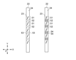
- FIG. 12 is a diagram showing an example of surface low-friction processing on the facing surface 24. As shown in FIG.
- the facing surface 24 of the read head 22 includes a first region 51 corresponding to the region where the servo elements 23 are provided in the length direction (Y-axis direction) of the read head 22, and a second region 52 corresponding to a region where no servo element 23 is provided in the vertical direction (Y-axis direction).
- the width (X-axis direction) of the second region 52 on the facing surface 24 is configured to be narrower than the width of the first region 51 .
- the shape of the groove 53 is semicircular, but the shape of the groove may be rectangular or the like, and the shape is not particularly limited.
- the facing surface 24 of the read head 22 includes a first region 51 corresponding to the region where the servo elements 23 are provided in the length direction (Y-axis direction) of the read head 22, and a second region 52 corresponding to a region where no servo element 23 is provided in the vertical direction (Y-axis direction).
- the second region 52 is provided with a plurality of grooves 54 elongated in the width direction (X-axis direction) of the read head 22 and aligned in the length direction (Y-axis direction) of the read head 22 . .
- the width of the second region 52 may be narrower than the width of the first region 51, and a plurality of grooves 54 may be provided in the second region 52 as shown on the right side of FIG. .
- the item of “individual” in the servo read head 20 is that the first servo element 23a (“/”) and the second servo element 23b (“ ⁇ ”) are different read heads 22, respectively. means that it is located in This is common to all comparative examples and examples.
- the "number of read head sections" in the servo read head 20 indicates the number of read head sections 21.
- one read head section 21 two read heads 22
- the fourth comparative example, fifth comparative example, first embodiment, second embodiment, and third comparative example are provided.
- there are two read head units 21 four read heads 22).
- each reproducing head unit 21 has a plurality of servo bands corresponding to numbers skipping by two and not overlapping each other (first number, second number, and third number). It is configured to read servo patterns.
- the "arrangement order" in the servo reproducing head 20 is the arrangement of the reproducing head 22 including the first servo element 23a ("/") and the reproducing head 22 including the second servo element 23b (" ⁇ "). shows the order of 6, the left side is the upstream side of the magnetic tape 1 in the conveying direction.
- the reproducing head 22 including the first servo element 23a (“/")
- the second servo element The playback heads 22 are arranged in the order of the playback heads 22 including 23b (" ⁇ ").
- adjacent “/” and “ ⁇ ” indicate two read heads 22 included in one read head unit 21 .
- FIG. 13 is a perspective view of the servo reproducing head 20 according to the seventh embodiment, viewed from the side facing the magnetic tape.
- each reproducing head 22 is arranged in order from the upstream side (the left side in FIG. 13) in the conveying direction of the magnetic tape 1 to the first reproducing head of the first reproducing head section 21a.
- 22a (“/”), the third playback head 22c (“/”) of the second playback head section 21b, the second playback head 22b (“ ⁇ ”) of the first playback head section 21a, the second They are arranged in order of the fourth reproducing head 22d (" ⁇ ") of the reproducing head section 21b.
- the order of arrangement of the four or more reproducing heads 22 in this embodiment can be changed as appropriate.
- the arrangement order pattern is 4! Although there are 24 patterns, any arrangement may be used. Similarly, when the number of the read head units 21 is 3 or more and the number of the read head units 21 is 6 or more, any arrangement may be adopted.
- the number in parentheses is the number of the reproducing head unit 21, and (1) "/" (1) " ⁇ ” (2) “/” (2) “ ⁇ ” pattern, (2) “/” (2 ) " ⁇ ” (1) "/” (1) " ⁇ ” pattern, (1) " ⁇ ” (1) "/” (2) “ ⁇ ” (2) “/” pattern, (2) " ⁇ ” (2) “/” (1) " ⁇ ” (1) "/”.
- the other 20 patterns are patterns in which the two read heads 22 in at least one of the first read head section 21a and the second read head section 21b are not adjacent to each other.
- the item "position adjustment mechanism" in the servo read head 20 indicates whether or not there is a position adjustment mechanism capable of attaching a plurality of read heads 22 and adjusting the positions of the plurality of read heads 22. .
- the position adjusting mechanism is provided in all the comparative examples and the working examples.
- one read head unit 31, 41 (two read heads 32, 42) is configured to read servo patterns in all servo bands. Therefore, the pitch (in the Y-axis direction) of each servo element 23 in the reproducing head units 31 and 41 is equal to the pitch of the servo band of the magnetic tape 1 .
- the pitch of each servo element 23 is relatively wide (2859 ⁇ m), and therefore the servo patterns in all servo bands can be read. .
- the number of servo bands of the magnetic tape 1 is increased to 10 and 13, and the pitch of each servo element 23 is narrow (1280 ⁇ m, 980 ⁇ m). It is not possible to read the servo pattern in any servo band.
- a coil is used as the signal reading section 26, but since this coil is coil-shaped, it is relatively large in size. Therefore, if the pitch (Y-axis direction) of each servo element 23 is narrowed, the coil itself cannot be arranged, and the servo pattern cannot be read.
- the first embodiment is configured such that two read head units 21 (four read heads 22) share and read servo patterns in all servo bands. , are the same as in the second comparative example.
- the two reproducing head units 21 are configured to share and read the servo patterns in all the servo bands. , are the same as in the third comparative example.
- two read heads 21 are configured to share and read all servo bands.
- the pitch of the servo elements 23 can be widened (2560 ⁇ m, 1960 ⁇ m). Therefore, even if the number of servo bands is increased and the pitch of the servo bands is narrowed for high-density data recording, the servo patterns in all servo bands can be accurately read and reproduced. This is the same for the third to eighth embodiments.
- the two read head units 21 are configured to share and read the servo patterns in all the servo bands.
- the pitch (in the Y-axis direction) of each servo band on the magnetic tape 1 is as narrow as 600 ⁇ m. narrow as. Therefore, in the fourth comparative example, it is impossible to read servo patterns in all servo bands.
- the configuration of the magnetic tape 1 is the same as that of the fourth comparative example, the number of the reproducing head units 21 is three (the number of the reproducing heads 22 is six), and each servo element 23 is The pitch (in the Y-axis direction) is 1800 ⁇ m, which is three times the pitch (600 ⁇ m) of the servo band. Therefore, in the third embodiment, a sufficient distance can be taken as the pitch of the servo elements 23, so that the servo patterns in all servo bands can be read accurately.
- the width (Y-axis direction) of the servo band on the magnetic tape 1 is 93 ⁇ m.
- the width (Y-axis direction) of the servo band on the magnetic tape 1 is set to 70 ⁇ m, which is narrower than in the first embodiment.
- Other configurations are common to the first embodiment and the fourth embodiment.
- both the first embodiment and the fourth embodiment can appropriately read servo patterns in all servo bands. Therefore, in this embodiment, the width of the servo band is typically set to 93 ⁇ m or less, 70 ⁇ m or less, or the like.
- the central portion of the servo element 23 has a form in which the servo pattern can be read (see the left side of FIG. 11).
- the servo pattern cannot be read (see the right side of FIG. 11).
- Other configurations are common to the first embodiment and the fifth embodiment.
- both the first embodiment and the fifth embodiment can appropriately read servo patterns in all servo bands. Therefore, in the present embodiment, the servo pattern may be readable in the central portion of the servo element 23, and the servo pattern may not be readable in the central portion of the servo element 23'.
- the servo element 23 is of the inductive type.
- the servo element 23 is of the MR type.
- Other configurations are common to the first embodiment and the sixth embodiment.
- the servo patterns in all servo bands can be read appropriately in both the first embodiment and the sixth embodiment.
- the type of the servo element 23 may be an inductive type, an MR type, a GMR type, a TMR type, or the like.
- the servo element 23 is of the inductive type, there is an arrangement problem based on the size of the signal reading section 26 (coil) as described above, so this technology is adopted when the servo element 23 is of the inductive type. is particularly effective.
- the order of arrangement of the read head 22 including the first servo element 23a ("/") and the read head 22 including the second servo element 23b (“ ⁇ ") is "/ ⁇ / ⁇ ” is the order. That is, in the first embodiment, the two read heads 22 in the first read head portion 21a are adjacent in the width direction (X-axis direction), and the two read heads 22 in the second read head portion 21b are adjacent to each other. It is considered as the form which adjoins in the width direction.
- the order of arrangement of the read head 22 including the first servo element 23a ("/") and the read head 22 including the second servo element 23b (" ⁇ ") is "// ⁇ ⁇ ” (see FIG. 13). That is, in the seventh embodiment, the two read heads 22 in at least one of the first read head portion 21a and the second read head portion 21b are adjacent in the width direction (X-axis direction). It is considered as a form that does not. Other configurations are common to the first embodiment and the seventh embodiment.
- the servo patterns in all servo bands can be read appropriately in both the first embodiment and the seventh embodiment. Therefore, in the present embodiment, the adjacent configuration may be employed, or the non-adjacent configuration may be employed.
- the item "reproduction head friction increase” in the characteristics means the degree of frictional resistance between the servo reproduction head 20 (facing surface 24) and the magnetic tape 1.
- the number of the reproducing head units 31 and 41 is one (there are two reproducing heads 32 and 42), so the friction between the servo reproducing heads 30 and 40 and the magnetic tape 1 is Resistance is normal.
- the number of the read head units 21 is two (the number of read heads 22 is four). Therefore, the frictional resistance between the servo reproducing head 20 and the magnetic tape 1 is high.
- the number of reproducing head units 21 is three (the number of reproducing heads 22 is six), the frictional resistance between the servo reproducing head 20 and the magnetic tape 1 is even higher.
- the frictional resistance between the servo reproducing head 20 and the magnetic tape 1 is high, the servo pattern reading accuracy of the servo reproducing head 20 may be adversely affected. Accuracy may be adversely affected.
- the facing surface 24 of each read head 22 is not subjected to low-friction processing, while in the eighth embodiment, the facing surface 24 of each read head 22 is subjected to low-friction processing. (See FIG. 12).
- Other configurations are common to the first embodiment and the eighth embodiment.
- the number of the reproducing head units 21 is two or more (the number of the reproducing heads 22 is four or more), and since the number of the reproducing head units 21 is large, the friction between the servo reproducing head 20 and the magnetic tape 1 is reduced. resistance tends to be high.
- Frictional resistance can be suppressed.
- the item "magnetic tape running stability” in the characteristics means the running stability of the magnetic tape 1 when the magnetic tape 1 passes the position of the servo reproducing head 20.
- the running of the magnetic tape 1 is unstable in the fifth comparative example, the running of the magnetic tape 1 is stable in the other comparative examples and working examples.
- the length (Y-axis direction) of the read head 22 is set to 19.3 mm, but in the fifth comparative example, the length of the read head 22 is shorter than that in the first embodiment, i.e., 18 mm. .3 mm.
- Other configurations are common to the first embodiment and the fifth comparative example.
- the positions of the two read head units 21 are shifted in the length direction (Y-axis direction) of the read head 22 . Therefore, the short length of the read head 22 (18.3 mm) prevents the read head 22 from properly contacting the entire width of the magnetic tape 1 (12.656 mm). Therefore, in the fifth comparative example, the running of the magnetic tape 1 is unstable.
- the length (Y-axis direction) of the reproducing head section 21 is typically 19.3 mm or more.
- the servo reproducing head 20 has a plurality of first servo bands, which are some of all the servo bands (eg, #0 to #8) on the magnetic tape 1. (for example, #0, #2, #4, #6, and #8), and a plurality of second servos, which are part of other servo bands. and a second reproducing head unit 21b for reading servo patterns recorded in bands (eg, #1, #3, #5, and #7).
- first servo bands which are some of all the servo bands (eg, #0 to #8) on the magnetic tape 1. (for example, #0, #2, #4, #6, and #8), and a plurality of second servos, which are part of other servo bands.
- a second reproducing head unit 21b for reading servo patterns recorded in bands (eg, #1, #3, #5, and #7).
- the reading of the servo pattern can be shared by two or more reproducing head units 21 for each servo band group. Therefore, for example, even if the number of servo bands is increased and the pitch of the servo bands is narrowed for high density recording of data, the servo patterns in all the servo bands can be read accurately.
- the first reproducing head unit 21a includes a plurality of read head units 21a corresponding to the first numbers (for example, #0, #2, #4, #6, #8) that are skipped by at least one number. is configured to read the servo patterns recorded in the first servo bands (eg, #0, #2, #4, #6, #8) of the .
- the second reproducing head section 21b corresponds to a second number (eg, #1, #3, #5, #7) that is at least one skipped number and is different from the first number. It is configured to read servo patterns recorded in a plurality of second servo bands (eg, #1, #3, #5, #7).
- the first read head section 21a and the second read head section 21b each have a plurality of servo elements 23 for reading servo patterns.
- the plurality of servo elements 23 are arranged in the length direction (Y-axis direction) of the reproducing head section 21 at a pitch that is an integral multiple of the pitch of the servo band and is at least twice as large as that of the servo band.
- the first read head portion 21a and the second read head portion 21b are arranged with their positions shifted in the length direction of the read head portion 21 (Y-axis direction).
- the reproducing head 22 having the same configuration can be used as the reproducing head 22 used for the first reproducing head section 21a and the second reproducing head section 21b.
- the servo recording/reproducing apparatus 100 is particularly effective when used as an apparatus for reading servo patterns of the magnetic tape 1 having a large number of servo bands and a narrow pitch of the servo bands.
- the servo recording/reproducing apparatus 100 is used as an apparatus for reading servo patterns on the magnetic tape 1 having nine or more servo bands. Also, the servo recording/reproducing apparatus 100 according to the present embodiment is used, for example, as an apparatus for reading a servo pattern on a magnetic tape 1 having a servo band pitch (in the Y-axis direction) of 1280 ⁇ m or less.
- the servo recording/reproducing apparatus 100 according to the present embodiment is used as a device for reading servo patterns on a magnetic tape 1 having eight servo bands or less, or a magnetic tape 1 having a servo band pitch exceeding 1280 ⁇ m. It is not the intention that it cannot be done. That is, the servo recording/reproducing apparatus 100 according to the present embodiment may be used as an apparatus for reading a servo pattern on a magnetic tape 1 having eight servo bands or less, or a magnetic tape 1 having a servo band pitch exceeding 1280 ⁇ m. .
- the servo reproducing head 20 may be of an inductive type. In this case, the problem of arrangement based on the size of the signal reading section 26 (coil) is resolved. is particularly advantageous.
- the servo reproducing head 20 may be of another type such as an MR type.
- the number of the reproducing head units 21 is two or more (the number of the reproducing heads 22 is four or more), and the number of the reproducing head units 21 is large. Frictional resistance tends to increase. Therefore, it is particularly effective to reduce the frictional resistance between the servo reproducing head 20 and the magnetic tape 1 by the low-friction processing as described above.
- the length (Y-axis direction) of the read head portion 21 (read head 22) is 19.3 mm or more, the running stability of the magnetic tape 1 can be improved.
- the length (Y-axis direction) of the reproducing head section 21 (reproducing head 22) can be appropriately changed according to the width of the magnetic tape 1 (for example, 12.656 mm).
- the length of the reproducing head section 21 needs to be increased as much as possible).
- the present technology can also adopt the following configuration. (1) a first reproducing head unit for reading servo patterns recorded in a plurality of first servo bands which are part of the plurality of servo bands in a magnetic tape having a plurality of servo bands; a servo reproducing head having a second reproducing head unit for reading servo patterns recorded in a plurality of second servo bands which are part of the servo bands of the servo reproducing apparatus.
- the servo reproduction device When numbers are sequentially assigned to the plurality of servo bands in the width direction of the magnetic tape, The servo reproducing apparatus, wherein the first reproducing head section reads the servo patterns recorded in the plurality of first servo bands corresponding to the first numbers that are skipped by at least one number. (3) The servo reproducing device according to (2) above, The second reproducing head reads servo patterns recorded in the plurality of second servo bands corresponding to second numbers that are skipped by at least one and that are different from the first numbers. playback device.
- the plurality of servo bands are arranged at a first pitch in the width direction of the magnetic tape;
- the first read head section and the second read head section have a length direction in the width direction of the magnetic tape,
- the first read head portion and the second read head portion are servo elements that read the servo pattern, and the length direction of each read head portion is an integral multiple and two or more times the first pitch.
- a servo reproducing device each having a plurality of servo elements arranged at a second pitch of .
- the servo reproducing device has a length direction in the width direction of the magnetic tape, A servo reproducing apparatus in which the first reproducing head section and the second reproducing head section are arranged such that their positions in the length direction of each reproducing head section are shifted.
- the first read head portion and the second read head portion have a width direction in the length direction of the magnetic tape;
- the first read head section and the second read head section each have a first region corresponding to the position where the servo element is provided in the length direction of each read head section, and a length of each read head section.
- the width in the width direction of each read head portion in the second region is narrower than the width of the first region;
- a plurality of grooves are formed along the width direction of each reproducing head portion and aligned in the length direction of each reproducing head portion in the second region on the facing surface.
- the servo reproducing apparatus according to any one of (1) to (7) above, The magnetic tape has a width of 12.656 mm or less in the width direction of the magnetic tape.
- the servo reproducing device according to (8) above, The magnetic tape has 9 or more servo bands.
- a servo reproducing device (10) The servo reproducing device according to any one of (1) to (9) above, The servo reproducing device, wherein each of the plurality of servo bands has a width of 93 ⁇ m or less in the width direction of the magnetic tape.
- the servo reproducing device according to any one of (1) to (10) above, The first read head section and the second read head section have a length direction in the width direction of the magnetic tape, The servo reproducing apparatus, wherein the first reproducing head portion and the second reproducing head portion have a length of 19.3 mm or more in the longitudinal direction of each reproducing head portion.
- the servo reproducing device according to any one of (1) to (11) above, The servo reproducing apparatus, wherein the first reproducing head section and the second reproducing head section are of an inductive type.
- the servo pattern includes a first servo pattern inclined at a first azimuth angle with respect to the width direction of the magnetic tape, and a first servo pattern inclined with respect to the width direction of the magnetic tape at a direction opposite to the first azimuth angle. and a second servo pattern that is slanted at an azimuth angle of 2.
- the servo reproducing device includes the first reproducing head for reading the first servo pattern and the second reproducing head for reading the second servo pattern in the plurality of first servo bands.
- the second reproducing head unit includes the third reproducing head for reading the first servo pattern and the fourth reproducing head for reading the second servo pattern in the plurality of second servo bands. having a servo playback device.
- the first read head portion and the second read head portion have a width direction in the length direction of the magnetic tape; the two read heads of the first read head section are adjacent to each other in the width direction of each read head section; The two read heads of the second read head section are adjacent to each other in the width direction of each read head section.
- the first read head portion and the second read head portion have a width direction in the length direction of the magnetic tape; The two read heads of at least one of the first read head section and the second read head section are not adjacent to each other in the width direction of each read head section.
- a servo read head comprising: a second read head section for reading servo patterns recorded in a plurality of second servo bands that are part of other servo bands.
- a reproducing head having a plurality of servo elements for respectively reading servo patterns recorded in the plurality of servo bands on a magnetic tape having a plurality of servo bands, the reproducing head has a length direction in the width direction of the magnetic tape and a width direction in the length direction of the magnetic tape;
- the read head has a first region corresponding to a position where the servo element is provided in the length direction of the read head and a position where the servo element is not provided in the length direction of the read head.
- the width of the second region in the width direction of the read head is narrower than the width of the first region in the first direction, or Alternatively, a plurality of grooves are formed along the width direction of the read head and aligned in the length direction of the read head in the second region on the facing surface.
- a first reproducing head unit for reading servo patterns recorded in a plurality of first servo bands, which are part of the plurality of servo bands in a magnetic tape having a plurality of servo bands; reading the servo patterns by a servo reproducing head having a second reproducing head unit for reading the servo patterns recorded in a plurality of second servo bands that are part of the servo bands of the A magnetic tape manufacturing method for confirming whether or not the servo pattern has been written correctly based on information of the read servo pattern.
Landscapes
- Engineering & Computer Science (AREA)
- Signal Processing (AREA)
- Adjustment Of The Magnetic Head Position Track Following On Tapes (AREA)
Priority Applications (2)
| Application Number | Priority Date | Filing Date | Title |
|---|---|---|---|
| US18/696,512 US12562188B2 (en) | 2021-11-05 | 2022-09-30 | Servo reproduction apparatus, servo reproduction head, reproduction head, and method of producing a magnetic tape |
| JP2023557893A JPWO2023079870A1 (https=) | 2021-11-05 | 2022-09-30 |
Applications Claiming Priority (2)
| Application Number | Priority Date | Filing Date | Title |
|---|---|---|---|
| JP2021-180775 | 2021-11-05 | ||
| JP2021180775 | 2021-11-05 |
Publications (1)
| Publication Number | Publication Date |
|---|---|
| WO2023079870A1 true WO2023079870A1 (ja) | 2023-05-11 |
Family
ID=86241407
Family Applications (1)
| Application Number | Title | Priority Date | Filing Date |
|---|---|---|---|
| PCT/JP2022/036636 Ceased WO2023079870A1 (ja) | 2021-11-05 | 2022-09-30 | サーボ再生装置、サーボ再生ヘッド、再生ヘッド及び磁気テープの製造方法 |
Country Status (3)
| Country | Link |
|---|---|
| US (1) | US12562188B2 (https=) |
| JP (1) | JPWO2023079870A1 (https=) |
| WO (1) | WO2023079870A1 (https=) |
Citations (4)
| Publication number | Priority date | Publication date | Assignee | Title |
|---|---|---|---|---|
| JP2008542969A (ja) * | 2005-06-03 | 2008-11-27 | イメイション・コーポレイション | データ記憶媒体の分散サーボパターン |
| US20140268409A1 (en) * | 2012-07-10 | 2014-09-18 | International Business Machines Corporation | Determining a skew error signal (ses) offset used to determine an ses to adjust heads in a drive unit |
| JP2021034113A (ja) * | 2019-08-16 | 2021-03-01 | ソニー株式会社 | 磁気記録媒体 |
| JP2021114352A (ja) * | 2020-01-20 | 2021-08-05 | ソニーグループ株式会社 | 磁気記録媒体 |
Family Cites Families (7)
| Publication number | Priority date | Publication date | Assignee | Title |
|---|---|---|---|---|
| US6169640B1 (en) * | 1998-03-04 | 2001-01-02 | Hewlett-Packard Co. | Servo band identification in linear tape systems having timing based servo formats |
| US6430008B1 (en) * | 2000-03-30 | 2002-08-06 | Storage Technology Corporation | Measurement of tape position error |
| US7193812B2 (en) * | 2003-07-25 | 2007-03-20 | International Business Machines Corporation | Recording head compensation for tape shrinkage and expansion |
| US7978429B2 (en) * | 2006-09-19 | 2011-07-12 | International Business Machines Corporation | Low track pitch write module and bidirectional tape head |
| US7920356B2 (en) * | 2008-02-01 | 2011-04-05 | International Business Machines Corporation | Method and system for providing a longitudinally shifted servo pattern for increased sampling rate |
| JP6206252B2 (ja) | 2013-03-15 | 2017-10-04 | ソニー株式会社 | 磁気記録媒体、サーボ信号記録装置及び磁気記録媒体の製造方法 |
| US9997184B1 (en) * | 2017-11-09 | 2018-06-12 | International Business Machines Corporation | Hybrid servo pattern configurations for magnetic tape |
-
2022
- 2022-09-30 US US18/696,512 patent/US12562188B2/en active Active
- 2022-09-30 JP JP2023557893A patent/JPWO2023079870A1/ja active Pending
- 2022-09-30 WO PCT/JP2022/036636 patent/WO2023079870A1/ja not_active Ceased
Patent Citations (4)
| Publication number | Priority date | Publication date | Assignee | Title |
|---|---|---|---|---|
| JP2008542969A (ja) * | 2005-06-03 | 2008-11-27 | イメイション・コーポレイション | データ記憶媒体の分散サーボパターン |
| US20140268409A1 (en) * | 2012-07-10 | 2014-09-18 | International Business Machines Corporation | Determining a skew error signal (ses) offset used to determine an ses to adjust heads in a drive unit |
| JP2021034113A (ja) * | 2019-08-16 | 2021-03-01 | ソニー株式会社 | 磁気記録媒体 |
| JP2021114352A (ja) * | 2020-01-20 | 2021-08-05 | ソニーグループ株式会社 | 磁気記録媒体 |
Also Published As
| Publication number | Publication date |
|---|---|
| US12562188B2 (en) | 2026-02-24 |
| JPWO2023079870A1 (https=) | 2023-05-11 |
| US20240386911A1 (en) | 2024-11-21 |
Similar Documents
| Publication | Publication Date | Title |
|---|---|---|
| US11790941B2 (en) | Total dimensional stability compensation system and method for magnetic tape drive | |
| US7551393B2 (en) | Tape recording head with multiple planes of transducer arrays | |
| US8526138B2 (en) | Tandem magnetic writer with independently addressable coils | |
| US8035926B2 (en) | System including a pivot assembly for adjusting misalignment and skew between a read/write head and a flexible data storage media | |
| US20050152067A1 (en) | System with matrix array of write heads and matrix array of magnetoresistive (MR) read heads | |
| WO2020090124A1 (ja) | サーボパターン記録方法、サーボパターン記録装置、テープ状磁気記録媒体の製造方法及びテープ状磁気記録媒体 | |
| US8867167B2 (en) | Tapered pole heads for magnetic media | |
| US7002777B2 (en) | Tape drive head with lower core layer side inclined at angle equal to or greater than azimuth angle and aligned with upper core layer edge | |
| US20050007700A1 (en) | Tape recording system and head device | |
| JP6817981B2 (ja) | 磁気テープ、磁気テープの製造方法、磁気テープの製造装置、及び記録再生システム | |
| US11195550B2 (en) | Servo write head, servo pattern recording apparatus, method of producing magnetic tape, and magnetic tape | |
| JP2005092941A (ja) | 磁気テープおよびサーボライタ | |
| US20250095678A1 (en) | Servo recording apparatus, servo write head, method of producing a magnetic tape, and magnetic tape | |
| Biskeborn et al. | Hard-disk-drive technology flat heads for linear tape recording | |
| WO2023079870A1 (ja) | サーボ再生装置、サーボ再生ヘッド、再生ヘッド及び磁気テープの製造方法 | |
| JP2016126803A (ja) | 磁気記録再生装置 | |
| JP2005276359A (ja) | 磁気ヘッド装置、回転ヘッド装置、磁気テープ装置、磁気ディスク装置、磁気記録方法 | |
| US11875828B2 (en) | Magnetic storage reader having a bridge to align magnetic moments | |
| JP7651913B2 (ja) | 磁気ヘッド、サーボパターン記録装置、テープドライブ装置、磁気テープの製造方法および記録方法 | |
| US6515833B1 (en) | Rotating drum assembly and magnetic recording/reproducing apparatus having a tape-contact piece | |
| US20040223260A1 (en) | Method and apparatus for a side-by-side thin film head with minimal separation between the read and write structures | |
| US6940672B2 (en) | Azimuthal transition layout for two-sided data storage tape | |
| US8797681B2 (en) | Servo write head having plural spaced front blocks coupled by magnetic posts to a back bar | |
| US20250124947A1 (en) | Probe head with trailing shield for magnetic recording on tape | |
| US7268971B2 (en) | Magnetic head apparatus and drive apparatus including magnetic head apparatus |
Legal Events
| Date | Code | Title | Description |
|---|---|---|---|
| 121 | Ep: the epo has been informed by wipo that ep was designated in this application |
Ref document number: 22889694 Country of ref document: EP Kind code of ref document: A1 |
|
| WWE | Wipo information: entry into national phase |
Ref document number: 18696512 Country of ref document: US |
|
| ENP | Entry into the national phase |
Ref document number: 2023557893 Country of ref document: JP Kind code of ref document: A |
|
| NENP | Non-entry into the national phase |
Ref country code: DE |
|
| 122 | Ep: pct application non-entry in european phase |
Ref document number: 22889694 Country of ref document: EP Kind code of ref document: A1 |
|
| WWG | Wipo information: grant in national office |
Ref document number: 18696512 Country of ref document: US |