WO2023074867A1 - タイヤの回転方向主溝深さの測定方法、及びその方法を利用した回転方向主溝深さの測定装置 - Google Patents
タイヤの回転方向主溝深さの測定方法、及びその方法を利用した回転方向主溝深さの測定装置 Download PDFInfo
- Publication number
- WO2023074867A1 WO2023074867A1 PCT/JP2022/040471 JP2022040471W WO2023074867A1 WO 2023074867 A1 WO2023074867 A1 WO 2023074867A1 JP 2022040471 W JP2022040471 W JP 2022040471W WO 2023074867 A1 WO2023074867 A1 WO 2023074867A1
- Authority
- WO
- WIPO (PCT)
- Prior art keywords
- depth
- light
- tire
- coordinates
- main groove
- Prior art date
- Legal status (The legal status is an assumption and is not a legal conclusion. Google has not performed a legal analysis and makes no representation as to the accuracy of the status listed.)
- Ceased
Links
Images


Classifications
-
- G—PHYSICS
- G01—MEASURING; TESTING
- G01B—MEASURING LENGTH, THICKNESS OR SIMILAR LINEAR DIMENSIONS; MEASURING ANGLES; MEASURING AREAS; MEASURING IRREGULARITIES OF SURFACES OR CONTOURS
- G01B11/00—Measuring arrangements characterised by the use of optical techniques
- G01B11/22—Measuring arrangements characterised by the use of optical techniques for measuring depth
-
- G—PHYSICS
- G01—MEASURING; TESTING
- G01B—MEASURING LENGTH, THICKNESS OR SIMILAR LINEAR DIMENSIONS; MEASURING ANGLES; MEASURING AREAS; MEASURING IRREGULARITIES OF SURFACES OR CONTOURS
- G01B11/00—Measuring arrangements characterised by the use of optical techniques
- G01B11/24—Measuring arrangements characterised by the use of optical techniques for measuring contours or curvatures
- G01B11/25—Measuring arrangements characterised by the use of optical techniques for measuring contours or curvatures by projecting a pattern, e.g. one or more lines, moiré fringes on the object
Definitions
- the present invention relates to the measurement of the depth of the main groove in the rotational direction formed on the tread surface of a tire such as an automobile or motorcycle.
- the present invention relates to a method for measuring the depth of the main groove in the rotational direction of a tire based on the captured image, and a measuring apparatus using the method.
- Tires of vehicles such as automobiles if worn beyond a certain level, may break while the vehicle is running and cause a serious accident, so it is necessary to replace them with new tires at an appropriate time. It has become.
- Tire life depends not only on the mileage of the vehicle, but also on individual factors such as the type of vehicle, the condition of the road surface on which the tire is constantly driven, and the habits of the driver. It is not appropriate to make a judgment based on the number of tires, but it is important to investigate the wear condition of each tire and make a judgment.
- the main factors that govern the life of tires are the wear of the tread surface and the occurrence of scratches such as cracks and cuts.
- the progress of wear on the tread surface is often judged from the depth of the tire groove. That is, longitudinal grooves (circumferential grooves) and lateral grooves are formed on the tread surface in the direction of rotation of the tire in order to release water trapped between the road surface and the tire to the rear or side of the tire.
- a laser displacement meter is often used as means for three-dimensionally measuring the shape of the surface of an object.
- a laser displacement gauge measures the remaining groove depth of a tire.
- Patent Document 1 while rotating the tire around its rotation axis, the tread surface of the tire is irradiated with incident light from a predetermined direction, and the reflected light at a predetermined angle with respect to the incident light is received by a light receiving portion. and acquires tire tread depth data.
- the measurement of the residual groove depth by the laser displacement gauge has the following problems.
- a fan-shaped light beam is created by a laser or a shadowed light-emitting diode as a light source for irradiating transversely to the direction of travel of the tire. Since the measurements are made non-orthogonal to the surface of the tire, neither the light source nor the sensor are located at the angular direction of direct reflection.
- the sensor is in this case a two-dimensional image analysis camera. The evaluation is done by generating a measured tire tread envelope and looking for the deepest points of the tread grooves.
- the deepest part of the tread groove is determined as the remaining groove depth of the tire by the light section method.
- longitudinal grooves (circumferential grooves) and lateral grooves are formed on the tread surface of the tire in the direction of rotation of the tire, it is determined whether the determined grooves are longitudinal grooves (circumferential grooves) or lateral grooves. I can't.
- a tire in use may have various irregularities. Therefore, there is a problem that a groove determined to be a circumferential groove may not actually be a circumferential groove.
- Patent Document 3 captures an image of line light (image of a light-section line) irradiated on the surface of a relatively moving object to be measured (surface of a rotating tire, etc.), and light-section based on the captured image.
- a shape measuring apparatus and method for detecting the surface shape of an object to be measured by performing shape detection using a method is disclosed.
- Patent Document 3 irradiates the surface of the object to be measured with a plurality of line lights from a direction different from the detection height direction of the surface of the object to be measured.
- line light irradiation means for forming a plurality of separated light-section lines extending in a second direction orthogonal to one direction and having mutually displaced ranges in the second direction; and a plurality of lines formed on the surface of the object to be measured.
- an imaging means for imaging an image of the separated light-section line in the direction in which the principal ray of each of the plurality of line lights is specularly reflected on the surface of the object to be measured; For each of the plurality of captured images obtained, light sectioning is performed from each of the images of the plurality of independent image processing target regions preset corresponding to the plurality of separated light section lines in the coordinate system of the captured image of the imaging means.
- light-section line coordinate detecting means for individually detecting light-section line coordinates that are coordinates of the line image; and a first direction of the object to be measured based on the plurality of light-section line coordinates detected by the light-section line coordinate detection means and surface shape calculating means for calculating the surface height distribution in the shape measuring apparatus.
- the shape measuring device disclosed in Patent Document 3 below measures the shape of the side surface of the tire and the shape of the tread surface of the tire while rotating the tire, thereby determining the shape of the entire tire. It is what you measure. For this reason, in this technology, a plurality of separated line lights are irradiated onto the tread surface of the tire, and the coordinates of the images of the line lights are detected by the light-section line coordinate detection means corresponding to each line light, so that the tire is rotating. Even if there is no delay in the processing.
- JP-A-2016-161360 Japanese Patent No. 5640073 Japanese Patent No. 5089286
- the present invention is a device for measuring the depth of the main groove (circumferential groove) in the direction of rotation of the tire formed on the tread surface of the tire removed from a vehicle such as an automobile or motorcycle, and the manufacturing cost of the device is To provide a device for measuring the depth of the main groove in the rotational direction of the tread surface of a tire which is low in cost and maintenance cost and which can be easily measured.
- the first aspect of the present invention for solving the above problems is to irradiate the tread surface of the tire with a line laser beam in a direction transverse to the rotation direction of the tire, and capture an image of the line laser beam on the tread surface with a camera.
- a method for measuring the depth of a main groove in the rotational direction, in which an image is captured and the depth of a plurality of main grooves in the rotational direction formed on the tread surface is detected by an optical section method based on the captured image, irradiating at least two different locations on the tread surface with a line laser beam, and capturing images of the line laser beam, respectively; Detecting light-section line coordinates, which are coordinates of the image of the line laser light, for each of the captured images, calculating groove depths formed on the tread surface based on the triangulation method from the light-section line coordinates, A depth of a main groove in the rotational direction formed on a tread surface of a tire, characterized in that a depth of the groove at which the coordinates in the
- a second aspect of the present invention is a captured image obtained by irradiating the tread surface of a tire with a line laser beam in a direction transverse to the rotation direction of the tire, and capturing an image of the line laser beam on the tread surface with a camera.
- a third aspect of the present invention is a line laser beam irradiation device for irradiating a line laser beam onto at least two different locations on the tread surface of the tire in a direction transverse to the rotational direction of the tire; a camera that captures an image of the line laser light on the tread surface; a line laser image detection unit that detects an image of line laser light from an image captured by the camera; a light-section line coordinate detection unit that detects light-section line coordinates that are coordinates of an image of the line laser light; a groove depth calculator that calculates the depth of the grooves formed on the tread surface from the light-section line coordinates based on the light-section method; a main groove determination unit configured to determine each of a plurality of grooves in which the coordinates of the calculated depth of the groove in the rotation direction substantially match each other as a rotation direction main groove.
- line laser light is applied to at least two different locations on the tread surface of the tire, and an image of the line laser light on the tread surface of the tire is captured by a camera. An image of the line laser light is detected from each captured image, and light-section line coordinates, which are the coordinates of the image of the line laser light, are detected.
- the depth of the groove can be calculated from the arrangement of the line laser light irradiation device and the camera, and the coordinates of the light-cutting line, based on the triangulation method using the principle of the light-cutting method.
- a point A which is one coordinate of the light-section line coordinates, and a distance w away from the point A in a direction transverse to the tire rotation direction point B, which is one coordinate of the light-section line coordinates
- point C which is one coordinate of the light-section line coordinates, which is separated from the point A by 2w in a direction transverse to the rotation direction of the tire.
- the area of the triangle formed by the point A, the point B, and the point C is repeated until any one of the points A, B, and C becomes all the coordinates of the light-section line coordinates.
- a groove depth is calculated from the quadratured area of the triangle, and groove depths having the groove depth equal to or greater than a predetermined value and having substantially the same coordinates in the rotation direction are determined as main rotation directions. Determine the depth of the groove.
- the tread surface of the tire is a gently curved surface
- the image of the line laser light picked up by the camera also has a gently curved surface. Therefore, when calculating the groove depth, it is necessary to calculate the groove depth in a direction perpendicular to the normal line of the light section line divided (separated) by the groove portion. For that purpose, 3 points are selected from the light-section line coordinates, the area of the triangle composed of the 3 points is quadratured for all the light-section line coordinates, and the maximum value of the groove depth obtained from there is calculated as the groove Depth is preferably determined.
- point A which is one coordinate of light-section line coordinates
- point B which is one coordinate of light-section line coordinates
- point C which is one coordinate of the light-section line coordinates separated from point A by 2w in a direction transverse to the tire rotation direction.
- a device for measuring the depth of the main groove (circumferential groove) in the direction of rotation of the tire formed on the tread surface of the tire removed from a vehicle such as an automobile or motorcycle It has become possible to provide a device for measuring the depth of the main groove in the rotational direction of the tread surface of a tire, which is low in maintenance cost and easy to measure.
- the apparatus for measuring the depth of the rotational direction main groove formed on the tread surface of a tire according to the present invention is characterized by low equipment cost, easy maintenance, and simple measurement.
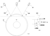
- FIG. 1 is a perspective view showing the construction of a measuring apparatus 1 for measuring the depth of a main groove in the tread surface of a tire according to the first embodiment of the present invention.
- This apparatus includes a table 50 on which a tire 40 is placed, a line laser light irradiation device 10, a camera 20 for capturing an image of the line laser light, and a data processing device 30 for analyzing and processing the image captured by the camera.
- a light source that makes the tread surface of the tire 40 clear according to environmental conditions.
- the tire 40 is placed on the table 50 so that the tire side surface is horizontal.
- the line laser beam irradiation device 10 is arranged symmetrically with respect to the camera 20, and irradiates the tread surface of the tire 40 with line laser beams in a direction transverse to the rotation direction of the tire so as to irradiate two different points on the tread surface.
- Forms an image of line laser light The camera 20 captures images of line laser light appearing at two different locations on the tread surface, and the captured images are sent to the data processing device 30 .
- the purpose of the line laser light image is to obtain information on the remaining groove depth of the tire 40 . In the embodiment shown in FIG.
- the camera 20 is arranged between the two line laser light irradiation devices 10, but the present invention is not limited to this, and is based on the principle of the light section method. It suffices if the arrangement (height, distance, angle, etc.) relationship between the camera 20, the line laser beam irradiation device 10, and the tread surface of the tire, which is necessary for the triangulation method used, can be specified.
- the present invention when acquiring a line laser beam image of the tread surface in a direction transverse to the rotating direction of the tire, two different locations on the tread surface are irradiated with the line laser beam and captured by the camera 20. There is a feature in the place to do. This is because the tread surface is formed with lateral grooves and oblique grooves in addition to the main grooves in the direction of rotation, and the tread surface may become uneven due to use. The reason why the line laser light is applied to two different places on the tread surface is to distinguish between the main grooves in the rotational direction and the other grooves. Here, it is preferable to simultaneously irradiate two different locations on the tread surface with the line laser beam. You can go with that.
- the characteristic that the rotational direction main grooves are always continuous in the rotational direction is used. That is, from the coordinates of the light cutting line 11 (see FIG. 3), which is the image of the line laser beam, the grooves whose coordinates in the rotation direction are substantially the same are determined as the main grooves in the rotation direction. It is a point. However, there are cases where the main grooves are formed in a meandering shape in the tire rotation direction, and there are cases where the main grooves are not necessarily continuous in the rotation direction due to the relationship with the lateral grooves. Even with such a main groove, from the coordinates of the light-section line 11, grooves whose coordinates in the rotational direction are substantially the same are determined as rotational direction main grooves.
- FIG. 2 shows the height direction of the camera 20 of the measuring device 1 according to the embodiment of the present invention shown in FIG. It is a figure showing positional relationship.
- the line laser beam irradiation devices 10 are arranged symmetrically in the rotation direction of the tire 40 with the camera 20 interposed therebetween.
- the irradiation angle of the line laser beam irradiation device 10 is an angle for irradiating the center of the tire 40, which is the object to be measured.
- the diameter of the tire to be measured varies, for example, the angle for irradiating the center of the tire with the smallest diameter is set.
- the height of the camera 20 from the tread surface is set to a height at which images of two line laser beams can be acquired (a viewing angle can be secured), and the camera 20 is installed at the same height as that height.
- D is the depth of the rotational direction main groove 41 of the tire 40
- ⁇ is the incident angle of the line laser beam 100 onto the tread surface of the tire 40
- w is the width of the main groove 41
- D tan ⁇ w.
- w is wider than the width of the main groove 41, and is preferably about 1 to 2 times the width of the main groove 41, for example. This is because the width of the main groove may change due to wear of the tire, and the main groove may be formed in a meandering shape in the tire rotation direction.
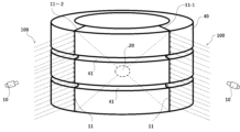
- FIG. 3 is a diagram of a tire placed with its side surface horizontal, and a line laser beam emitted from the line laser beam irradiation device 10 to the tread surface of the tire 40 .
- Line laser beams 100 are irradiated from two line laser beam irradiation devices 10 to two different locations on the tread surface, and two light cutting lines 11, which are images of the line laser beams, appear on the tread surface.
- the image of the light cutting line 11 appears not as an image reflected from the tread surface but as an image reflected from the bottom surface of the main groove 41 at the location where the tire rotational direction main groove 41 is formed. That is, as shown in FIG. 2(b), the image of the light cutting line 11 of the main groove 41 of the light cutting line 11 is more sensitive to the depth of the main groove 41 than the image appearing on the tread surface. Appears on the irradiation direction side.
- the characteristic that the main grooves in the rotational direction are continuous in the rotational direction is used as a discriminating means.
- two line laser light images are generated on the tread surface, and the coordinates of the light cutting lines 11 (light cutting line 11-1, light cutting line 11-2) that are the images of the line laser light (light cutting line coordinates), grooves with matching coordinates in the direction of rotation are determined as main grooves in the direction of rotation.
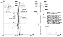
- FIG. 4 is a diagram showing an embodiment of the present invention in which the depth of the main groove in the rotational direction is calculated from the light cutting line 11, which is the image of the line laser light.
- the tire groove gauge tire groove depth gauge
- the groove depth is measured so that it hits the This is because the tread surface is a gently curved surface.
- the depth of the main groove can be calculated by the triangulation method from the distance h between the line laser light image of the tread surface and the line laser light image of the main groove.
- the distance between the light-section line coordinates of the tread surface and the light-section line coordinates of the main groove differs depending on how the coordinates are taken.
- the coordinate axes shown in FIG. 4 represent the resolution of an image of the tread surface of 1000 ⁇ 1000 dots, that is, the coordinates of the X-axis are 0-1000 and the coordinates of the Y-axis are 0-1000.
- a point B which is one coordinate of the light-section line 11
- a point C which is one coordinate of the light-section line 11, which is separated from the point A by 2w in a direction transverse to the rotating direction of the tire are selected.
- each groove depth is calculated. is 1.6 mm, and 0.8 mm for two-wheels) or more is determined as the depth of the main groove.
- FIG. 5 is a block diagram showing the configuration of a measuring device 1 for measuring the depth of a main groove in the tread surface of a tire according to one embodiment of the present invention.
- the two line laser beam irradiation devices 10 irradiate line laser beams to different locations on the tread surface of the tire.
- a camera 20 captures an image of the line laser light appearing on the tread surface.
- the line laser control section 310 of the control section 31 controls the line laser light irradiation device 10
- the imaging control section 311 of the control section 31 controls the camera 20 .
- the data processing unit 32 includes a line laser image detection unit 320 that detects an image of the line laser light, and a light cutting line that detects the coordinates of the line laser light image detected by the line laser image detection unit 320.
- a main groove determination unit 323 for determining the rotational direction main groove.
- FIG. 6 shows the depth of the main groove in the rotational direction of the tire (size: 215/55R17) obtained by measuring the depth of the main groove in the rotational direction formed on the tread surface of the tire according to one embodiment of the present invention. It is a diagram.
- the line laser has a wavelength of 600 nm, a power consumption of 40 mW, a power supply voltage of 5 VD, and a resolution of the camera 20 of 2048 ⁇ 1536.
- the image acquired with such specifications was processed, the coordinates of the light cutting line 11 were obtained, and the depth of the main groove in the rotational direction was calculated.
- a depth of 5.9 mm was detected from
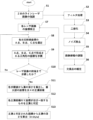
- FIG. 7 is a flow chart showing an example of a method for measuring the depth of the main groove in the rotational direction according to one embodiment of the present invention.
- linear interpolation is performed on pixels (defective points) that originally exist in the image of the line laser beam but have disappeared (S5, S6), and the coordinates of the light cutting line 11, which is the image of the line laser beam, are extracted (S7). ).
- points A, B, and C are selected from the coordinates of each light-section line 11, and the area of a triangle formed by points A, B, and C is quadratured (S8, S9). This is repeated until the point A becomes the coordinate of all the light-section lines 11, the area of the triangle formed by the points A, B, and C is quadratured (S10), the area of the triangle is taken as the Y axis, The maximum value of the graph with the Y-axis coordinate of the light cutting line 11 as the X-axis is taken as a main groove candidate (S11).
- the Y-coordinate of the light-section line 11 is substantially the same. If not, it is determined to be the main groove in the rotational direction. Then, the depth of the main groove is calculated from the area of the groove determined to be the main groove (S12, S13).
- FIG. 1 is a perspective view showing the configuration of a tire rotation direction main groove depth measuring device formed on a tread surface of a tire according to an embodiment of the present invention
- FIG. 1 is a view showing the positional relationship in the height direction between a camera, a line laser beam irradiation device, and a tread surface of a tire of a tire rotation direction main groove measuring device according to an embodiment of the present invention
- FIG. 2 is an irradiation diagram of line laser light that is applied to the tread surface of a tire by a line laser irradiation device that is an embodiment of the present invention.
- FIG. 1 is a perspective view showing the configuration of a tire rotation direction main groove depth measuring device formed on a tread surface of a tire according to an embodiment of the present invention
- FIG. 1 is a view showing the positional relationship in the height direction between a camera, a line laser beam irradiation device, and a tread surface of a tire of a tire rotation direction main groove measuring device according to an embodiment of the present invention
- FIG. 4 is a diagram showing an embodiment of the present invention in which the depth of the main groove in the rotational direction is calculated from the cutting line coordinates 11 that are the image of the line laser beam.
- 1 is a block diagram showing the configuration of a measuring device 1 for measuring the depth of a main groove in the tread surface of a tire according to an embodiment of the present invention
- FIG. FIG. 4 is a diagram of the depth of a rotational direction main groove obtained by a line laser irradiation device that is an embodiment of the present invention
- 4 is a flow chart showing an example of a method for measuring the depth of the main groove in the rotational direction formed on the tread surface of the tire according to one embodiment of the present invention.
- Tire rotation direction main groove measuring device 10 Line laser beam irradiation device 20: Camera 30: Data processing device 31: Control unit 32: Data processing unit 40: Tire 41: Tire rotation direction main groove 50: Table 310 : Line laser control unit 311: Imaging control unit 320: Line laser image detection unit 321: Light cutting line coordinate detection unit 322: Groove depth calculation unit 323: Main groove determination unit
Landscapes
- Physics & Mathematics (AREA)
- General Physics & Mathematics (AREA)
- Engineering & Computer Science (AREA)
- Computer Vision & Pattern Recognition (AREA)
- Length Measuring Devices By Optical Means (AREA)
- Tires In General (AREA)
Priority Applications (2)
| Application Number | Priority Date | Filing Date | Title |
|---|---|---|---|
| PCT/JP2023/016781 WO2024089917A1 (ja) | 2021-10-29 | 2023-04-27 | タイヤの回転方向主溝深さの測定方法、及びその方法を利用した回転方向主溝深さの測定装置 |
| JP2024552817A JPWO2024089917A1 (enExample) | 2021-10-29 | 2023-04-27 |
Applications Claiming Priority (2)
| Application Number | Priority Date | Filing Date | Title |
|---|---|---|---|
| JP2021178378A JP7694951B2 (ja) | 2021-10-29 | 2021-10-29 | タイヤの回転方向主溝深さの測定方法、及びその方法を利用した回転方向主溝深さの測定装置 |
| JP2021-178378 | 2021-10-29 |
Publications (1)
| Publication Number | Publication Date |
|---|---|
| WO2023074867A1 true WO2023074867A1 (ja) | 2023-05-04 |
Family
ID=86159524
Family Applications (2)
| Application Number | Title | Priority Date | Filing Date |
|---|---|---|---|
| PCT/JP2022/040471 Ceased WO2023074867A1 (ja) | 2021-10-29 | 2022-10-28 | タイヤの回転方向主溝深さの測定方法、及びその方法を利用した回転方向主溝深さの測定装置 |
| PCT/JP2023/016781 Ceased WO2024089917A1 (ja) | 2021-10-29 | 2023-04-27 | タイヤの回転方向主溝深さの測定方法、及びその方法を利用した回転方向主溝深さの測定装置 |
Family Applications After (1)
| Application Number | Title | Priority Date | Filing Date |
|---|---|---|---|
| PCT/JP2023/016781 Ceased WO2024089917A1 (ja) | 2021-10-29 | 2023-04-27 | タイヤの回転方向主溝深さの測定方法、及びその方法を利用した回転方向主溝深さの測定装置 |
Country Status (2)
| Country | Link |
|---|---|
| JP (3) | JP7694951B2 (enExample) |
| WO (2) | WO2023074867A1 (enExample) |
Cited By (1)
| Publication number | Priority date | Publication date | Assignee | Title |
|---|---|---|---|---|
| US12444065B2 (en) * | 2022-09-22 | 2025-10-14 | Hyundai Motor Company | Apparatus, method and computer readable storage medium for measuring depth of tread groove |
Families Citing this family (1)
| Publication number | Priority date | Publication date | Assignee | Title |
|---|---|---|---|---|
| JP7694951B2 (ja) * | 2021-10-29 | 2025-06-18 | 中央海産株式会社 | タイヤの回転方向主溝深さの測定方法、及びその方法を利用した回転方向主溝深さの測定装置 |
Citations (4)
| Publication number | Priority date | Publication date | Assignee | Title |
|---|---|---|---|---|
| JPH0743325B2 (ja) * | 1987-11-20 | 1995-05-15 | 株式会社日立製作所 | 欠け検査装置 |
| JP2002277409A (ja) * | 2001-03-15 | 2002-09-25 | Olympus Optical Co Ltd | プリント基板パターンの検査装置 |
| JP2016001165A (ja) * | 2014-06-12 | 2016-01-07 | 株式会社ブリヂストン | タイヤの外観検査方法 |
| WO2020202632A1 (ja) * | 2019-03-29 | 2020-10-08 | 株式会社ブリヂストン | 周方向主溝検出方法及び周方向主溝検出装置 |
Family Cites Families (3)
| Publication number | Priority date | Publication date | Assignee | Title |
|---|---|---|---|---|
| JPH04309479A (ja) * | 1991-04-05 | 1992-11-02 | Toshiba Corp | 溶接線検出装置 |
| JP2018054356A (ja) * | 2016-09-27 | 2018-04-05 | 株式会社日本マイクロニクス | ガス検知用フィルム、ガス検知装置、及びガス検知方法 |
| JP7694951B2 (ja) * | 2021-10-29 | 2025-06-18 | 中央海産株式会社 | タイヤの回転方向主溝深さの測定方法、及びその方法を利用した回転方向主溝深さの測定装置 |
-
2021
- 2021-10-29 JP JP2021178378A patent/JP7694951B2/ja active Active
-
2022
- 2022-10-28 WO PCT/JP2022/040471 patent/WO2023074867A1/ja not_active Ceased
-
2023
- 2023-04-27 WO PCT/JP2023/016781 patent/WO2024089917A1/ja not_active Ceased
- 2023-04-27 JP JP2024552817A patent/JPWO2024089917A1/ja active Pending
-
2025
- 2025-02-10 JP JP2025019912A patent/JP2025076484A/ja active Pending
Patent Citations (4)
| Publication number | Priority date | Publication date | Assignee | Title |
|---|---|---|---|---|
| JPH0743325B2 (ja) * | 1987-11-20 | 1995-05-15 | 株式会社日立製作所 | 欠け検査装置 |
| JP2002277409A (ja) * | 2001-03-15 | 2002-09-25 | Olympus Optical Co Ltd | プリント基板パターンの検査装置 |
| JP2016001165A (ja) * | 2014-06-12 | 2016-01-07 | 株式会社ブリヂストン | タイヤの外観検査方法 |
| WO2020202632A1 (ja) * | 2019-03-29 | 2020-10-08 | 株式会社ブリヂストン | 周方向主溝検出方法及び周方向主溝検出装置 |
Cited By (1)
| Publication number | Priority date | Publication date | Assignee | Title |
|---|---|---|---|---|
| US12444065B2 (en) * | 2022-09-22 | 2025-10-14 | Hyundai Motor Company | Apparatus, method and computer readable storage medium for measuring depth of tread groove |
Also Published As
| Publication number | Publication date |
|---|---|
| JP2025076484A (ja) | 2025-05-15 |
| WO2024089917A1 (ja) | 2024-05-02 |
| JP2023067290A (ja) | 2023-05-16 |
| JPWO2024089917A1 (enExample) | 2024-05-02 |
| JP7694951B2 (ja) | 2025-06-18 |
Similar Documents
| Publication | Publication Date | Title |
|---|---|---|
| US10311835B1 (en) | Method for detection and estimation of tire tread wear | |
| JP2025076484A (ja) | タイヤの回転方向主溝深さの測定方法、及びその方法を利用した回転方向主溝深さの測定装置 | |
| US10241195B1 (en) | Method for assessing a condition of an axle of a moving vehicle | |
| US8254666B2 (en) | Method for the determination of the wheel geometry and/or axle geometry of motor vehicles | |
| US10586346B2 (en) | Device and method for the analysis and detection of geometrical features of an object | |
| US9779560B1 (en) | System for multi-axis displacement measurement of surfaces on a moving vehicle | |
| US7535558B2 (en) | Method for optical chassis measurement | |
| US20170254727A1 (en) | Mesh Registration System and Method for Diagnosing Tread Wear | |
| US10789773B2 (en) | Mesh registration system and method for diagnosing tread wear | |
| US11472234B2 (en) | Mesh registration system and method for diagnosing tread wear | |
| US20170124784A1 (en) | System and method for multiple feature detection and analysis of a rotating tire | |
| EP2353890A1 (en) | Apparatus and method of determing geometrical dimensions of a tyre with optical sensors | |
| CN101365922A (zh) | 用来确定车辆的车轴几何位置的方法 | |
| US10068389B1 (en) | Method and apparatus for evaluating an axle condition on a moving vehicle | |
| CN1283265A (zh) | 测定汽车的车轮和/或轴几何定位参数的装置 | |
| AU2018425917A1 (en) | Apparatus and method for calculating wooden crosstie plate cut measurements and rail seat abrasion measurements based on rail head height | |
| CN111295564A (zh) | 光学轮评估 | |
| CN106996750A (zh) | 一种轮胎花纹深度测量装置及轮胎花纹深度计算方法 | |
| CN106600966A (zh) | 一种基于激光雷达的车辆轮轴识别系统及方法 | |
| KR102513815B1 (ko) | 자동화된 선로 이상 탐지 방법 및 그 장치 | |
| US10408610B1 (en) | Method and system for displacement measurement of surfaces on a moving vehicle | |
| US12361538B1 (en) | Detection and estimation of defects in vehicle's exterior | |
| KR102882885B1 (ko) | 테스트 벤치에서 차량의 머드가드 에지를 측정하는 방법 | |
| CN216846130U (zh) | 轮胎花纹深度测量系统 | |
| KR102464145B1 (ko) | 3차원 스캔을 이용한 노면상태 조사장치 및 이를 이용한 노면상태 조사 방법 |
Legal Events
| Date | Code | Title | Description |
|---|---|---|---|
| 121 | Ep: the epo has been informed by wipo that ep was designated in this application |
Ref document number: 22887192 Country of ref document: EP Kind code of ref document: A1 |
|
| NENP | Non-entry into the national phase |
Ref country code: DE |
|
| 122 | Ep: pct application non-entry in european phase |
Ref document number: 22887192 Country of ref document: EP Kind code of ref document: A1 |