WO2023074480A1 - Gas analysis device and control method - Google Patents
Gas analysis device and control method Download PDFInfo
- Publication number
- WO2023074480A1 WO2023074480A1 PCT/JP2022/038848 JP2022038848W WO2023074480A1 WO 2023074480 A1 WO2023074480 A1 WO 2023074480A1 JP 2022038848 W JP2022038848 W JP 2022038848W WO 2023074480 A1 WO2023074480 A1 WO 2023074480A1
- Authority
- WO
- WIPO (PCT)
- Prior art keywords
- gas
- plasma
- detector
- sample
- detection result
- Prior art date
Links
- 238000000034 method Methods 0.000 title claims abstract description 136
- 238000004868 gas analysis Methods 0.000 title claims abstract description 6
- 238000001514 detection method Methods 0.000 claims abstract description 125
- 230000008569 process Effects 0.000 claims abstract description 111
- 150000002500 ions Chemical class 0.000 claims abstract description 42
- 230000007246 mechanism Effects 0.000 claims abstract description 16
- 230000001360 synchronised effect Effects 0.000 claims abstract description 13
- 230000005684 electric field Effects 0.000 claims abstract description 9
- 239000007789 gas Substances 0.000 claims description 192
- 238000004458 analytical method Methods 0.000 claims description 67
- 238000001819 mass spectrum Methods 0.000 claims description 27
- 238000005259 measurement Methods 0.000 claims description 22
- 238000004611 spectroscopical analysis Methods 0.000 claims description 17
- 239000013307 optical fiber Substances 0.000 claims description 9
- 238000000295 emission spectrum Methods 0.000 claims description 8
- 239000006227 byproduct Substances 0.000 claims description 6
- 238000001914 filtration Methods 0.000 claims description 6
- 238000005530 etching Methods 0.000 claims description 4
- 238000012806 monitoring device Methods 0.000 claims description 4
- 238000004886 process control Methods 0.000 claims description 3
- 229910052581 Si3N4 Inorganic materials 0.000 claims description 2
- 230000004888 barrier function Effects 0.000 claims description 2
- 230000015572 biosynthetic process Effects 0.000 claims description 2
- 238000004140 cleaning Methods 0.000 claims description 2
- TWNQGVIAIRXVLR-UHFFFAOYSA-N oxo(oxoalumanyloxy)alumane Chemical compound O=[Al]O[Al]=O TWNQGVIAIRXVLR-UHFFFAOYSA-N 0.000 claims description 2
- 239000010453 quartz Substances 0.000 claims description 2
- VYPSYNLAJGMNEJ-UHFFFAOYSA-N silicon dioxide Inorganic materials O=[Si]=O VYPSYNLAJGMNEJ-UHFFFAOYSA-N 0.000 claims description 2
- HQVNEWCFYHHQES-UHFFFAOYSA-N silicon nitride Chemical compound N12[Si]34N5[Si]62N3[Si]51N64 HQVNEWCFYHHQES-UHFFFAOYSA-N 0.000 claims description 2
- 230000008878 coupling Effects 0.000 claims 1
- 238000010168 coupling process Methods 0.000 claims 1
- 238000005859 coupling reaction Methods 0.000 claims 1
- 238000012544 monitoring process Methods 0.000 description 14
- 230000001276 controlling effect Effects 0.000 description 13
- 230000006870 function Effects 0.000 description 10
- 239000004065 semiconductor Substances 0.000 description 7
- XKRFYHLGVUSROY-UHFFFAOYSA-N Argon Chemical compound [Ar] XKRFYHLGVUSROY-UHFFFAOYSA-N 0.000 description 6
- 230000008859 change Effects 0.000 description 6
- 230000035945 sensitivity Effects 0.000 description 6
- 230000003287 optical effect Effects 0.000 description 5
- 230000003595 spectral effect Effects 0.000 description 5
- 238000012545 processing Methods 0.000 description 4
- 238000001228 spectrum Methods 0.000 description 4
- 229910052786 argon Inorganic materials 0.000 description 3
- 238000001336 glow discharge atomic emission spectroscopy Methods 0.000 description 3
- 238000004519 manufacturing process Methods 0.000 description 3
- 238000004949 mass spectrometry Methods 0.000 description 3
- 239000000758 substrate Substances 0.000 description 3
- 238000005229 chemical vapour deposition Methods 0.000 description 2
- 238000004891 communication Methods 0.000 description 2
- 238000001816 cooling Methods 0.000 description 2
- 230000000694 effects Effects 0.000 description 2
- 239000010408 film Substances 0.000 description 2
- 238000009616 inductively coupled plasma Methods 0.000 description 2
- 238000005240 physical vapour deposition Methods 0.000 description 2
- 230000002123 temporal effect Effects 0.000 description 2
- 238000011144 upstream manufacturing Methods 0.000 description 2
- 229910018072 Al 2 O 3 Inorganic materials 0.000 description 1
- 230000003213 activating effect Effects 0.000 description 1
- 238000001636 atomic emission spectroscopy Methods 0.000 description 1
- 238000006243 chemical reaction Methods 0.000 description 1
- 238000011109 contamination Methods 0.000 description 1
- 239000002826 coolant Substances 0.000 description 1
- 238000012937 correction Methods 0.000 description 1
- 230000002596 correlated effect Effects 0.000 description 1
- 238000000151 deposition Methods 0.000 description 1
- 230000008021 deposition Effects 0.000 description 1
- 230000006866 deterioration Effects 0.000 description 1
- 238000010586 diagram Methods 0.000 description 1
- 239000000284 extract Substances 0.000 description 1
- 238000000605 extraction Methods 0.000 description 1
- 229910000856 hastalloy Inorganic materials 0.000 description 1
- 238000009434 installation Methods 0.000 description 1
- 238000005040 ion trap Methods 0.000 description 1
- 238000010030 laminating Methods 0.000 description 1
- 238000011068 loading method Methods 0.000 description 1
- 239000011159 matrix material Substances 0.000 description 1
- 238000000691 measurement method Methods 0.000 description 1
- 239000000203 mixture Substances 0.000 description 1
- 238000012986 modification Methods 0.000 description 1
- 230000004048 modification Effects 0.000 description 1
- 230000007935 neutral effect Effects 0.000 description 1
- 239000002245 particle Substances 0.000 description 1
- 230000002093 peripheral effect Effects 0.000 description 1
- 238000002360 preparation method Methods 0.000 description 1
- 238000003672 processing method Methods 0.000 description 1
- 239000000047 product Substances 0.000 description 1
- 239000000376 reactant Substances 0.000 description 1
- 238000007493 shaping process Methods 0.000 description 1
- 239000010409 thin film Substances 0.000 description 1
- 230000007704 transition Effects 0.000 description 1
Images


Classifications
-
- G—PHYSICS
- G01—MEASURING; TESTING
- G01N—INVESTIGATING OR ANALYSING MATERIALS BY DETERMINING THEIR CHEMICAL OR PHYSICAL PROPERTIES
- G01N21/00—Investigating or analysing materials by the use of optical means, i.e. using sub-millimetre waves, infrared, visible or ultraviolet light
- G01N21/17—Systems in which incident light is modified in accordance with the properties of the material investigated
- G01N21/25—Colour; Spectral properties, i.e. comparison of effect of material on the light at two or more different wavelengths or wavelength bands
- G01N21/27—Colour; Spectral properties, i.e. comparison of effect of material on the light at two or more different wavelengths or wavelength bands using photo-electric detection ; circuits for computing concentration
-
- G—PHYSICS
- G01—MEASURING; TESTING
- G01N—INVESTIGATING OR ANALYSING MATERIALS BY DETERMINING THEIR CHEMICAL OR PHYSICAL PROPERTIES
- G01N27/00—Investigating or analysing materials by the use of electric, electrochemical, or magnetic means
- G01N27/62—Investigating or analysing materials by the use of electric, electrochemical, or magnetic means by investigating the ionisation of gases, e.g. aerosols; by investigating electric discharges, e.g. emission of cathode
-
- H—ELECTRICITY
- H01—ELECTRIC ELEMENTS
- H01J—ELECTRIC DISCHARGE TUBES OR DISCHARGE LAMPS
- H01J49/00—Particle spectrometers or separator tubes
-
- H—ELECTRICITY
- H01—ELECTRIC ELEMENTS
- H01J—ELECTRIC DISCHARGE TUBES OR DISCHARGE LAMPS
- H01J49/00—Particle spectrometers or separator tubes
- H01J49/02—Details
- H01J49/10—Ion sources; Ion guns
-
- H—ELECTRICITY
- H01—ELECTRIC ELEMENTS
- H01J—ELECTRIC DISCHARGE TUBES OR DISCHARGE LAMPS
- H01J49/00—Particle spectrometers or separator tubes
- H01J49/02—Details
- H01J49/10—Ion sources; Ion guns
- H01J49/14—Ion sources; Ion guns using particle bombardment, e.g. ionisation chambers
Definitions
- the present invention relates to a gas analyzer and its control method.
- Japanese Patent Application Laid-Open No. 2016-27327 discloses that in a glow discharge optical emission spectrometry (GD-OES), a sample holder has an electrode (second electrode) having a sample fixing surface, and a sample fixing surface. and an outer cylinder portion and an inner cylinder portion (abutting portion). With the sample separated from the opening of the glow discharge tube, the open end of the inner cylindrical portion is brought into contact with the peripheral edge of the opening. The inside of the communicating glow discharge tube, the outer cylindrical portion, and the inner cylindrical portion is depressurized, and argon gas is supplied.
- GD-OES glow discharge optical emission spectrometry
- One aspect of the present invention is a sample chamber having a dielectric wall structure, into which a sample gas to be measured flows, and an electric field and/or a magnetic field via the dielectric wall structure.
- a plasma generation mechanism configured to generate a plasma in the sample chamber
- a gas input device configured to allow only the sample gas from the process to flow into the sample chamber
- a second detector that analyzes the emission of ions in the plasma in the sample chamber and outputs a second detection result synchronized with the first detection result of the first detector
- a gas analyzer having a detector. In this gas analyzer, plasma, which serves as an ion source for the first detector, can be subjected to emission analysis by the second detector.
- a common ionized sample can be synchronously, i.e., simultaneously, in parallel, or in different ways, with a presettable limited time interval (latency) or stagger specific to this gas analyzer. It can be analyzed and data for analysis can be generated that correlates detection results from these different methods.
- the first detection result includes a mass spectrum acquired by time division (time lapse), that is, acquired serially (sequentially) because it is necessary to change the detection conditions with the filter.
- the second detection result includes an emission spectrum obtainable in parallel by spectroscopy.
- This gas analyzer includes a sample chamber for generating a common plasma, which serves as an ion source and a light source, separately from the process, and includes first and second detectors whose routes are fixed in advance with respect to the sample chamber. include. Therefore, the first serial detection result and the second parallel detection result for the common plasma generated in the sample chamber can be synchronously acquired, and generated and output as analysis data in association with each other. can do.
- the first detection result can be obtained. It becomes possible to verify that the information is from the plasma maintained under the same conditions, for example, the process under the same conditions, and obtain more reliable analysis results.
- the volume of the common ion source and light emission source to be detected can be reduced, and the first detection result and the second detection result for the same target can be obtained.
- Obtainable Furthermore, it is also possible to limit the serially obtained mass spectrum to a region of interest (ROI). In this way, while confirming a wide range of information, it is possible to obtain more accurate analysis results for the ROI at short time intervals, including temporal fluctuations.
- ROI region of interest
- the gas analyzer is a first analyzer that analyzes the sample gas based on the first detection result and the second detection result synchronized with the first detection result with a time interval defined by the gas analyzer. may have Due to the difference in spectral interference between the first detection result and the second detection result, a more accurate analysis is possible by cooperating the detection results.
- Another aspect of the present invention is a method of controlling a system having a gas analyzer, comprising a first detection result of a first detector and a second detection result of a second detector; including synchronous output of Synchronously outputting a first detection result including a mass spectrum obtained by time division (serial) and a second detection result including a (parallel) emission spectrum synchronously comparable with the first detection result.
- a first detection result including a mass spectrum obtained by time division (serial) and a second detection result including a (parallel) emission spectrum synchronously comparable with the first detection result.
- the mass spectrum may include a mass spectrum restricted to a region of interest (ROI).
- ROI region of interest
- Another aspect of the present invention is a program (program product) for controlling a system with a computer by the method of controlling a system having the above gas analyzer.
- the program contains instructions for carrying out control of the system.
- the program may be recorded on an appropriate computer-readable medium and provided.
- FIG. 1 is a block diagram showing a schematic configuration of a process monitoring system including a gas analyzer;
- FIG. The figure which shows an example of the data for analysis.
- 4A-4D illustrate different examples of process monitoring systems including gas analyzers.
- FIG. 4 shows yet another example of a process monitoring system including a gas analyzer;
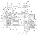
- FIG. 1 shows a schematic configuration of a process monitoring system 100 as an example of a system including the gas analyzer 1.
- a gas analyzer 1 analyzes a sample gas 9 supplied from a process chamber 101 in which a plasma process 102 is performed.
- the plasma process 102 carried out in the process chamber 101 is typically a step of forming various types of films or layers on a substrate or etching a substrate, and is a CVD (Chemical Vapor Deposition) process. ) or PVD (Physical Vapor Deposition).
- the plasma process 102 is not limited to processes related to semiconductor manufacturing, and may be processes for laminating various types of thin films using optical components such as lenses and filters as substrates.
- the gas analyzer 1 of this example In the process monitoring system 100 using the gas analyzer 1 of this example, it is possible to provide innovative process control by performing real-time monitoring even under harsh environments and providing highly reliable measurement results.
- the gas analyzer 1 functions as a total solution platform developed for the purpose of dramatically improving the throughput in semiconductor chip manufacturing and maximizing the yield rate.
- the gas analyzer 1 of this example can be directly connected to the chamber 101 because it has a very small installation area.
- a standard protocol that is currently mainly used in semiconductor manufacturing process equipment such as the Either Cat protocol, can be mounted on the PLC 50 and integrated into the process equipment control system 100.
- the gas analyzer 1 includes an ionization device 10 that generates ions (ion flow) 17 of a sample gas 9 and a sensor group that detects ions supplied from the ionization device 10 or generated in the ionization device 10. sensor suite, analysis group) 90.
- the ionization device 10 comprises a plasma generation unit (plasma generator) 11 for generating a plasma 19 of the sample gas 9 to be measured supplied from the process 102 via the sample input 3a.
- the plasma generation unit 11 comprises a dielectric wall structure 12a into which a sample gas 9 to be measured flows (sample chamber) 12, and through the dielectric wall structure 12a a high-frequency electric field and/or a magnetic field.
- the gas analyzer 1 includes a gas input device 5 configured to flow into the sample chamber 12 only the sample gas 9 from the process chamber 101 in which the plasma process 102 is performed.
- the gas analysis sensor group 90 includes a first detector 20 that filters ionized gas in the plasma 19 supplied as ions (ion flow) 17 to detect components in the plasma, and a second detector 80 for analyzing (spectroscopic analysis) the emission of the ions of .
- An example of the first detector (first sensor, first detector, first measuring device) 20 is a mass spectrometric detector (mass spectrometer, MS).
- the first detector 20 comprises a filter unit (mass filter, quadrupole filter in this example) 25 for filtering the ionized sample gas (sample gas ions) 17 by mass-to-charge ratio, and detects the filtered ions. and a detector 26 that
- the gas analyzer 1 further includes a vacuum container (housing) 40 containing the filter unit 25 and the detector 26, and an exhaust system 60 that maintains the inside of the housing 40 under an appropriate negative pressure condition (vacuum condition).
- the exhaust system 60 of this example includes a turbomolecular pump (TMP) 61 and a roots pump 62 .
- the exhaust system 60 is of the split-flow type that also controls the internal pressure of the sample chamber 12 of the plasma generator 11 .
- the stage that has a negative pressure suitable for the internal pressure of the chamber 12 or the input of the roots pump 62 communicates with the chamber 12 so that the internal pressure of the chamber 12 is controlled.
- the gas analyzer 1 of this example has an exhaust device 60 for exhausting gas from the sample chamber 12, and the exhaust device 60 bypasses the first detector 20 and exhausts gas from the sample chamber 12 as a first exhaust path. 65 and a second exhaust path 66 that exhausts through the first detector 20 .
- the sample chamber 12 is supplied with a sample gas flow rate separate from the gas flow flowing to the first detector 20 for filtering. It becomes possible to guide the gas 9 and control the internal pressure of the sample chamber 12 . Therefore, the amount of gas flowing through the first detector 20 can be stabilized, and the detection accuracy can be stabilized.
- sufficient sample gas 9 can be drawn into the sample chamber 12 from the process via the gas input device 5, it is possible to provide the gas analyzer 1 capable of monitoring the state (variation) in the process chamber 101 in real time.
- the mass filter 25 of this example includes four cylindrical or cylindrical electrodes 25a with inner hyperbolic surfaces to form a hyperbolic electric field for mass-to-charge ratio filtering.
- the quadrupole-type mass filter 25 may be one in which a large number of, for example, nine cylindrical electrodes are arranged to form a matrix (array) so as to form a plurality of quasi-hyperbolic electric fields.
- Detector 26 includes a Faraday Cap and a Secondary Electron Multiplier, which may be used in combination or interchangeably. Detector 26 may be of other types, such as a Channel Electron Multiplier, Microchannel Plate, or the like.
- the plasma generation device 11 of this example includes a sample chamber 12 for plasma generation that is integrally incorporated inside a housing 40 .
- the outer shell of the chamber 12 is made of Hastelloy, an insulated cylindrical electrode is inserted therein, and plasma 19 is generated therein. Only the sample gas 9 flows into the evacuated sample chamber 12 from the sample input 3a through the gas input device 5 from the process chamber 101 in which the process 102 to be monitored is performed, and a plasma 19 is formed inside the sample chamber 12. be done. That is, in the plasma generator 11, the analysis plasma 19 is generated only from the sample gas 9 without using an assist gas (support gas) such as argon gas.
- an assist gas support gas
- the wall 12a of the sample chamber 12 is made of a dielectric member (dielectric), for example quartz, aluminum oxide (Al 2 O 3 ) and silicon nitride (SiN 3 ). It is a light-transmitting dielectric with high durability.
- dielectric dielectric
- quartz for example quartz, aluminum oxide (Al 2 O 3 ) and silicon nitride (SiN 3 ). It is a light-transmitting dielectric with high durability.
- a mechanism (RF supply mechanism) 13 that specifically generates plasma generates an electric field and/or A plasma 19 is generated by the magnetic field.
- An example of the RF supply mechanism 13 is a mechanism that excites the plasma 19 with RF (Radio Frequency) power.
- Examples of the RF supply mechanism 13 include inductively coupled plasma (ICP), dielectric barrier discharge (DBD), and electron cyclotron resonance (ECR). .
- ICP inductively coupled plasma
- DBD dielectric barrier discharge
- ECR electron cyclotron resonance
- These types of plasma generating mechanisms 13 may include a radio frequency power source and an RF field forming unit.
- a typical RF field shaping unit includes coils arranged along the sample chamber 12 .
- the plasma generation device 11 of this example includes a function of igniting by changing the matching state by changing the frequency of the RF field.
- plasma can be generated and maintained by applying pulsed high-frequency power to ignite plasma and then transitioning to a steady operating state.
- the plasma generator 11 may be of a type in which an inductively coupled plasma (ICP) is formed by an assist gas such as argon gas and ionized by introducing a sample gas. is desirable, and the assist gas may be dispensed with by generating microplasma.
- ICP inductively coupled plasma
- the internal pressure of the sample chamber 12 of this example may be a pressure at which plasma is likely to be generated, for example, in the range of 0.01-1 kPa.
- the internal pressure of the sample chamber 12 may be controlled at a lower pressure, for example, about 0.1-several 10s Pa, 0.1 Pa or more, Alternatively, it may be controlled to 0.5 Pa or more, 10 Pa or less, or 5 Pa or less.
- the inside of the sample chamber 12 may be evacuated to about 1-10 mTorr (0.13-1.3 Pa).
- the sample chamber 12 may be small enough to generate the plasma 19, for example, a chamber having a total length of 1 to 100 mm and a diameter of 1 to 100 mm, and may be a chamber (miniature chamber) of several mm to several tens of mm. may By reducing the capacity of the sample chamber 12, it is possible to provide the gas analyzer 1 excellent in real-time performance.
- Sample chamber 12 may be cylindrical.
- the gas analyzer 1 includes an ionization device 10 and an electron ionization device (filament ionization device) that ionizes (electron ionizes) the sample gas 9 to be measured, which is supplied from the sample input 3b from the process 102 via the gas input device 5, by electron impact (electron ionization). , EI ion source) 15 .
- the EI ion source 15 operates in a high vacuum, and even when the process in the process chamber 101 to be monitored is in a high vacuum and conditions are such that it is difficult to generate the microplasma 19, the EI ion source 15 operates at the ultimate pressure of the gas analyzer 1, and furthermore, performs sensitivity correction.
- the gas supply device 5 comprises a connecting pipe 5c connected to the process chamber 101, a valve 5a controlling the flow of the sample gas 9 between the connecting pipe 5c and the sample input 3a for plasma ionization, the connecting pipe 5c and the EI and a valve 5b controlling the flow of sample gas 9 to and from the sample input 3b for ionization.
- the detection mode (measurement mode) of the gas analyzer 1 can be switched automatically or manually.
- the EI ion source 15 is provided between the sample input 3b and the filter unit 25, and is in a common flow path with the ion flow 17 from the plasma (microplasma) 19 formed in the sample chamber 12. facing.
- the EI ion source 15 is also capable of electron ionizing the sample gas 9 from the gas input device 5 and ionizing the gas from the sample chamber 12 (the plasma 19 derivative gas) to the first detector 20 . It is also possible to supply to
- the process controller 105 executes the highly reactive process 102 in a state where the internal pressure of the process chamber 101 is high, e.g. Gas 9 is supplied.
- the controller 50 of the gas analyzer 1 generates a plasma (microplasma) 19 of the sample gas 9, which is different from the process 102, from the sample gas 9, extracts ions 17 from the microplasma 19, and performs mass spectrometry.
- the EI ion source (filament) 15 is not lit and the valve (port) 5b is closed.
- the plasma side port (valve) 15a When the internal pressure of the process chamber 101 is low, for example, when measuring the ultimate pressure, the plasma side port (valve) 15a is closed and the EI side port 5b is opened to supply the sample gas 9 and light the filament ( The internal state of the process chamber 101 may be monitored by activating the EI).
- the gas analyzer 1 may include an energy filter 28 arranged between the EI ionization source 15 and the filter 25 .
- the energy filter 28 may be a Bessel-Box, a CMA (Cylindrical Mirror Analyzer), or a CHA (Concentric Hemispherical Analyzer).
- the Bessel box type energy filter 28 is composed of a cylindrical electrode, a disc-shaped electrode (same potential as the cylindrical electrode) placed in the center of the cylindrical electrode, and electrodes placed at both ends of the cylindrical electrode.
- the electric field created by the potential difference Vba and the potential Vbe of the cylindrical electrode act as a band-pass filter that allows only ions having a specific kinetic energy to pass through.
- soft X-rays generated during plasma generation and light generated during gas ionization can be prevented from directly entering the ion detector (detector) 26 by the disc-shaped electrode arranged at the center of the cylindrical electrode. , can reduce noise.
- the energy filter 28 can also eliminate ions and neutral particles that are generated in the ion generation section or outside and that enter the filter unit 25 parallel to the central axis, so that the structure is such that their detection can be suppressed.
- An example of the second detector (detector, analyzer, sensor) 80 is an emission spectrometer detector, typically an emission spectrometer (optical emission spectrometer, OES, atomic emission spectrometry , AES).
- An example of OES 80 is a receiving or collecting lens, such as an objective lens, attached to translucent dielectric wall structure 12a of sample chamber 12, in parallel with RF feed 13 or coaxial with RF feed 13's coil. It includes an optical element 81 , an optical fiber 82 that guides light from the light collecting element 81 , and a spectroscopic analysis unit (OES unit, OES detector) 85 that spectroscopically analyzes the light supplied by the optical fiber 82 .
- Spectroscopic analysis unit 85 may be any type of detector employed in OES 80, such as sequential or multi-channel.
- the gas analyzer 1 includes a control module 30 that controls each module of the analysis unit 20 under the PCL 50.
- the control module 30 includes a control module 35 for controlling the mass spectrometer 20, a unit 31 for controlling the extraction of the plasma 19, a unit 32 for controlling the electron ionizer 15, and the RF and DC voltages for the mass filter 25.
- a filter control function (filter control device) 33 that selects a region (region of interest, ROI) of an object (ion) to be controlled and measured by the filter 25, and a function (intensity detection device) 34.
- the control module 35 may include a function of controlling the potential of the lens group of the mass spectrometer 20, a function of controlling the potential of the energy filter 28, and the like.
- the control unit 32 of the EI unit 15 may include filament control functions to control filament current and voltage.
- a PLC (control device) 50 that controls the gas analyzer 1 includes computer resources such as a CPU 56 and a memory 55, and controls the gas analyzer 1 by loading and executing a program (program product) 59.
- the program 59 includes instructions for implementing and operating each function described below in the PLC 50 .
- the PLC 50 generates synchronized analysis data 53 by associating the first detection result 51 of the first detector 20 with the second detection result 52 of the second detector 80. Including functions as The program 59 can be recorded on a computer-readable medium and provided.
- FIG. 2 schematically shows the first detection result 51 and the second detection result 52.
- An example of the first detector 20 is a Mass Spectrometer (MS) that measures the mass and intensity of ionized elements in the plasma.
- An example of the first detection result 51 is the intensity to mass-to-charge ratio (m/z).
- An example of second detector 80 is an optical detector (OES) that measures the wavelength and intensity of light emitted from elements excited in the plasma.
- An example of the second detection result 52 is intensity versus wavelength.
- Features (advantages) of the first detector (MS) 20 over the second detector (OES) 80 include high sensitivity, wide dynamic lens, multi-element quantitative measurement, isotope ratio measurement, and spectral simplicity. etc. Disadvantages include reduced resolution due to mass spectral interferences.
- the second detection result 52 can basically be obtained with the sensitivity of the spectrometer, and the number of elements (components) contained in the sample gas 9 increases. There is no conversion to the measurement time (detection time). Further, the second detection result 52 includes information on all elements (components) as long as the spectrum can be obtained.
- the measurement time depends on the number of elements and mass numbers to be measured, and the first detection result 51 includes the measurement target (measured mass number ) are included.
- MS20 cannot separate elements (components) with the same mass-to-charge ratio m/z, and OES80 has difficulty separating elements (components) with spectra having the same or close frequencies. .
- the first detection result 51 includes a mass spectrum acquired by time division (lapse of time), that is, acquired serially (sequentially). That is, when spectrum acquisition is started at time t1 (51a), as shown at time t2, the mass-to-charge ratio m/z is searched in order (51b), and at time tn, the desired mass-to-charge m/z (region of interest , ROI) 51r can be obtained (mass spectrum 51c). Even with a relatively high-speed MS, it takes about 1 ms to measure with filter conditions set for one m/z, and it is possible to measure 1000 points (m/z) in one second. The measurement time is greatly increased compared to .
- the second detection result 52 includes an emission spectrum that can be acquired instantaneously (on the order of ms or less) at least in parallel with the first detection result 51 by spectroscopy. Therefore, the second detection results 52a, 52b and 52c obtained at times t1, t2 and tn are identical if the state of the microplasma 19 does not change. Therefore, the reliability of the serially obtained first detection result 51 can be ensured by synchronizing and associating the second detection result 52 and the first detection result 51 obtained in parallel. Synchronization between the first detection result 51 and the second detection result 52 mainly involves two latencies unique to this gas analyzer 1 .
- the first detection result 51 is the result of filtering the ion flow 17 supplied from the microplasma 19 by the filter 25, and the ions need to physically reach the detector 26. is. That is, when the microplasma 19 fluctuates, it takes time for the ions to physically reach the detector 26 of the first detector 20 to detect the fluctuation, and the state of the plasma 19 is different from the time difference. (latency).
- the second detection result 52 is the emission spectrum, and if there is a change in the state of the microplasma 19, it appears in the detection result without any time lag.
- the microplasma 19 generated in the fixed sample chamber 12 is an object to be inspected by the first detector 20 and the second detector 80, and the first detection result 51 and The time difference from the second detection result 52 can be set in advance as a unique value of the gas analyzer 1 . Therefore, the time difference between the first detection result 51 and the second detection result 52 is known in the generation device 57b, and the first detection result 51 and the second detection result 52 are synchronized for analysis. It can be generated as data 53 . As a result, detection results of the microplasma 19 at the same time by different methods can be obtained with high accuracy.
- the generation device 57b may synchronize all of the second detection results 52 while the mass spectrum 51 is being acquired and generate the data 53 for analysis.
- the generator 57b verifies that all the second detection results 52a-52c are the same while acquiring the mass spectrum 51, and generates the mass spectrum 51c when all the second detection results 52a-52c are the same. may be generated as analysis data 53 in synchronization with the second detection result 52c, and the mass spectrum 51c may be discarded when the conditions are not met.
- the generation device 57b may store the analysis data 53 generated in this manner in the memory 55, or may output the data to an external server or process controller 105 via the communication device 57d.
- the gas analyzer 1 includes a sample chamber 12 that generates a common plasma 19 that serves as an ion source and a light source separately from the process 102, and the sample chamber 12 has a preliminarily fixed route. 1 detector 20 and a second detector 80 . Therefore, the serial first detection result 51 and the parallel second detection result 52 for the common plasma 19 generated in the sample chamber 12 can be synchronously obtained and linked by the generator 57b. can be generated as analysis data 53 and output. Therefore, by checking the variation of the second detection result 52 acquired in parallel during the time interval during which the first detection result 51 acquired serially is obtained, the first detection result 51 is information from the plasma 19 maintained under the same conditions, for example, the process under the same conditions, and a more reliable analysis result can be obtained.
- minute microplasma 19 is generated in the sample chamber 12 of the gas analyzer 1 .
- the volume of the common ion source and light emission source that are the detection targets of the first detector 20 and the second detector 80 can be reduced, the bias in the plasma can be reduced, and the first detector for the same target can be reduced.
- a detection result 51 and a second detection result 52 can be obtained.
- ROI region of interest
- the PLC 50 further includes a plasma generation control device 57a that manages the generation state of the microplasma 19 via the plasma controller 16, and the filter 25 of the first detector 20 so that a mass spectrum in the desired ROI range can be obtained. It may include a ROI control device 57c for control, and a communication control device 57d for communicating with the process controller 105 and/or an external server or the like by wire and/or wireless.
- the PCL 50 further includes an analysis device (analysis unit, analysis function) 70 that analyzes components (elements) contained in the sample gas 9 based on analysis data 53 including the first detection result 51 and the second detection result 52.
- the analyzer 70 analyzes the sample gas 9 based on the first detection result 51 and the second detection result 52 synchronized with the first detection result 51 with a time interval defined by the gas analyzer 1.
- a first analyzer (first analysis unit) 71 may be provided.
- the first detector (MS) 20 cannot separate elements (components) having the same mass-to-charge ratio m/z, while the second detector (OES ) 80 is difficult to separate elements (components) with spectra having the same or close frequencies.
- components that cannot be separated in the first detection result 51 of the first detector 20 can be separated in the second detection result 52 of the second detector 80, and can be separated in the second detection result 52 of the second detector 80.
- Components that cannot be separated in the detection result 52 may be separated in the first detection result 51 of the first detector 20 .
- analysis data 53 is obtained by combining the first detection result 51 and the second detection result 52 which are temporally synchronized and highly reliable. Therefore, in the first analyzer 71, by cooperatively analyzing these data, it becomes possible to analyze the components of the sample gas 9 with higher accuracy.
- the analyzer (cooperative control module) 70 outputs the detection result 51 of the first detector 20 and the detection result 52 of the second detector 80 in parallel, or at a time interval defined by the gas analyzer 1 . is provided to acquire the processed analysis result.
- the gas analyzer 1 includes an electron ionizer 15 in addition to the sample chamber 12, so the following processing methods (processing modes) may be selected.
- a second analyzer 72 may be provided which selects one of the modes M1, M2 and M3 for analysis. (1) Detection of ionized components in the plasma 19 by the first detector 20 and emission analysis by the second detector 80 are performed in parallel (first mode, M1).
- the first detector 20 detects components by ionizing the gas derived from the plasma 19 with the electron ionization device 15, and the second detector 80 performs emission analysis in parallel (second mode, M2).
- the sample input 3b is closed by the upstream valve 5b.
- the sample input 3a is closed by the upstream valve 5a, and the sample gas 9 is supplied from the sample input 3b. may be ionized by the electron ionization device 15. In this case, no microplasma 19 is formed, so the detection result 52 by the second detector (OES) 80 is not obtained.
- OES second detector
- a process monitor (process monitoring device, process monitoring system) 100 is a process controller (process controller) 105.
- the process controller 105 may have computer resources such as a CPU and memory, and may be operated by a control program (program product) 109 .
- the process controller 105 may include an analysis device 70 having a common configuration with the PLC 50, and receives analysis data 53 from the gas analysis device 1, analyzes the sample gas 9, and performs 1 Or it may control multiple processes 102 .
- the process controller 105 has a device (endpoint controller) 110 for determining the endpoint of at least one plasma process 102 from the results of detection (measurement) of the sample gas 9 containing by-products of the plasma process by the gas analyzer 1. Including equipment. At least one plasma process 102 may include at least one of etching, film formation, and cleaning. In this process monitor 100 , a plasma 19 is generated independently of the process chamber 101 in the sample chamber 12 controlled by the gas analyzer 1 , so that the component by the first detector (mass spectrometer, MS) 20 is detected.
- MS mass spectrometer
- the process controller 105 can appropriately control the plasma process 102 based on the analysis.
- FIG. 3 is a flow chart showing an overview of how the process controller 105 controls the plasma process 102 .
- process 102 in process chamber 101 is initiated.
- the process controller 105 initiates the analysis of the sample gas 9 by the gas analyzer 1 .
- the components of the plasma 19 in the sample chamber 12 are detected by the first detector (MS) 20 and the second detector (OES) 80, and the first The detection result 51 and the second detection result 52 are synchronized to generate related analysis data 53 .
- the second detection result 52 information on a wide range of components can be obtained from the emission spectra obtained collectively and in parallel.
- the first detection result 51 only the mass spectrum (MS) limited to the region of interest (ROI) can be acquired, and highly accurate and highly sensitive information can be obtained.
- MS mass spectrum
- ROI region of interest
- the first analyzer 71 analyzes the components of the sample gas 9 based on the analysis data 53 .
- the measurement mode needs to be switched, in step 126 one of the first mode (M1), second mode (M2) and third mode (M3) is selected. You may
- step 127 the endpoint controller 110 of the process controller 105 determines the status and termination time of the process 102 based on the analysis results of the sample gas 9.
- step 128 the process End 102.
- the end of the process 102 may be determined by the endpoint controller 110 based on the detection result of the by-product of the plasma process 102 by the gas analyzer 1 . Thereafter, preparations are made to begin processing the next process, and the sequential process can be repeated to produce the product.
- FIG. 4 shows a different example of the process monitoring device 100.
- FIG. This process monitoring device 100 comprises a different example of gas analyzer 1 .
- the spectroscopic analysis unit 85 of the second detector 80 is arranged so as to be directly connected to the translucent dielectric wall structure 12 a of the sample chamber 12 . Therefore, the light from the plasma 19 in the sample chamber 12 can be spectroscopically analyzed without passing through the optical fiber, and the spectroscopically analyzed results can be obtained with higher accuracy.
- the spectroscopic analysis unit 85 adjacent to or coaxially with the wall 12a to which the RF for generating plasma is supplied, the plasma 19 is generated so as to treat the inner surface of the wall 12a with the plasma 19. can generate Therefore, it is possible to prevent a situation in which the inner surface of the wall 12a is contaminated with derivatives of the plasma 19 and the emitted light becomes difficult to see.
- This gas analyzer 1 comprises a first path 151 for supplying an ionized gas flow (ion flow) 17 from an opening 18 provided at one end of a sample chamber 12 to a first detector 20; and a second path 152 for supplying light from the other end of 12 for spectroscopic analysis by a second detector 80 .
- Light for spectroscopic analysis can be obtained from the opposite direction from which the ion stream 17 flows, suppressing unexpected variations in the second detection result 52 of the second detector 80 .
- FIG. 5 shows yet another example of the process monitoring system 100.
- This process monitoring system 100 includes yet another example of gas analyzer 1 .
- the sample chamber 12 of this gas analyzer 1 is cylindrical with a translucent dielectric side wall 12b and is a collector for guiding light via an optical fiber 82 to the spectroscopic analysis unit 85 of the second detector 80.
- An optical element 81 is attached to the side wall 12b. Therefore, this gas analysis apparatus 1 is capable of generating a flow of ionized gas (ion flow ) 17 and a third path 153 that provides light for spectroscopic analysis by the second detector 80 in a direction orthogonal to the first axis 155 of the sample chamber 12. .
- a third path 153 allows lateral access to the plasma 19 generated in the cylindrical chamber 12 . Therefore, the second detector 80 can perform emission analysis (spectroscopic analysis) using the emission of the atomized sample at the center of the plasma 19, and can obtain the detection result 52 with higher accuracy. .
- the place where the spectroscopic analysis unit 85 is arranged or the place where the optical fiber 82 is attached to obtain the light emission of the plasma 19 is not limited to the above.
- the above includes a sample chamber with a dielectric wall structure into which only the sample gas to be measured flows;
- a gas analyzer is disclosed that has a plasma generation mechanism that generates plasma and an analysis unit (sensor group) that analyzes a sample gas via the generated plasma.
- the analysis unit includes a first analyzer (first detector), for example a mass spectrometer, for filtering ionized gases in the plasma, and a second analyzer (first detector) for spectroscopically analyzing the ions in the plasma in the sample chamber. 2 detectors), such as an emission spectrometer.
- This analyzer can spectroscopically analyze the ion species and concentration of the plasma, which is the ion source of the first analyzer, by the second analyzer.
- a common ionized sample can be analyzed by different methods simultaneously in parallel or within a limited time interval (latency) within the gas analyzer, and the analysis results of those different methods can be combined in one analyzer.
- a third analyzer may be included that performs. In other words, the results of capturing the ionized gas in the plasma in the sample chamber without time lag by different analysis methods are compared, and the composition and concentration of the sample gas are analyzed with high accuracy, including temporal fluctuations. can.
- the second analyzer may comprise a unit for receiving light from the plasma in the sample chamber through a highly translucent dielectric wall structure, the inner surface of which is constantly refreshed by the plasma. Therefore, deterioration of analysis performance due to contamination can be suppressed.
- the second analyzer may be a spectroscopic analyzer connected to the sample chamber via an optical fiber, and in order to eliminate the effects of the optical fiber, the second analyzer emits light from the sample chamber without the optical fiber.
- the first analyzer may include an electron ionization unit that produces electrons for ionizing the sample gas.
- a process monitoring system having a gas analyzer.
- a process monitoring system is an example of a system having a gas analyzer and a process chamber in which a plasma process is performed and in which a sample gas is supplied to the gas analyzer.
- the above further discloses a method of analyzing the components of a sample gas with a gas analyzer.
- This method obtains the analysis results obtained by processing the analysis results of the first analyzer and the analysis results of the second analyzer in parallel or by providing a time interval defined by the gas analyzer. including. Even if there are components that cannot be separated by mass spectrometry due to the same charge ratio, high-precision analysis results can be obtained by analyzing the mass spectrometry results by adding ionization types obtained by spectroscopic analysis. There are many effects that can be obtained by collaborating with analysis.
- the first analyzer includes an electron ionization unit that generates ions for ionizing the sample gas, it may include the following measurement method.
- Analysis of the ionized gas in the plasma by the first analyzer and analysis of the gas in the plasma by the second analyzer are performed in parallel.
- the first analyzer ionizes the gas derived from the plasma by the electron ionization unit, and the second analyzer analyzes the gas in the plasma in parallel.
- the analysis of the gas ionized by the electron ionization unit by the first analyzer and the analysis of the gas in the plasma by the second analyzer are performed in parallel without passing through the plasma.
- a method of controlling a system having a process chamber for performing a plasma process has an analyzer as described above, only a sample gas from the process chamber flows into the sample chamber, and the method comprises a plasma process performed in the process chamber based on the measurement results of the gas analyzer.
- this filter 25 may be an ion trap, a Wien filter, or another type of filter. can be a type.
Abstract
A gas analysis device (1) comprises: a sample chamber (12) into which flows a sample gas (9) to be measured, the sample chamber being provided with a dielectric wall body structure; a plasma generation mechanism (13) that generates a plasma (19) inside a pressure-reduced sample chamber by using an electric field and/or a magnetic field through the dielectric wall body structure; a gas input device (5) configured such that only the sample gas flows from a process chamber (102) into the sample chamber; a first detector (20) that filters ionized gas in the generated plasma and detects components in the plasma; and a second detector (80) that analyzes the light emission of ions in the plasma of the sample chamber and can output a second detection result (52) synchronized with a first detection result (51) of the first detector.
Description
本発明は、ガス分析装置およびその制御方法に関するものである。
The present invention relates to a gas analyzer and its control method.
日本国特開2016-27327号公報には、グロー放電発光分析装置(GD-OES、Glow discharge optical emission spectrometry)において、試料ホルダは、試料固定面を有する電極(第2電極)と、試料固定面を内側に配置した外筒部及び内筒部(当接部)とを備える。グロー放電管の開口部から試料が離れた状態で、内筒部の開口端が開口部の周縁に当接される。連通したグロー放電管と外筒部及び内筒部との内部を減圧し、アルゴンガスを供給する。次に、内筒部を外筒部に対して動かして試料をグロー放電管の陽極(第1電極)の円筒部(端部)の先端に近づけ、流路(冷却部)に冷媒を流して試料を冷却し、電極に電圧を印加して、グロー放電発光分析を行うことが記載されている。
Japanese Patent Application Laid-Open No. 2016-27327 discloses that in a glow discharge optical emission spectrometry (GD-OES), a sample holder has an electrode (second electrode) having a sample fixing surface, and a sample fixing surface. and an outer cylinder portion and an inner cylinder portion (abutting portion). With the sample separated from the opening of the glow discharge tube, the open end of the inner cylindrical portion is brought into contact with the peripheral edge of the opening. The inside of the communicating glow discharge tube, the outer cylindrical portion, and the inner cylindrical portion is depressurized, and argon gas is supplied. Next, move the inner cylinder with respect to the outer cylinder to bring the sample closer to the tip of the cylindrical part (end) of the anode (first electrode) of the glow discharge tube, and let the coolant flow through the channel (cooling part). It describes cooling the sample and applying a voltage to the electrodes to perform glow discharge optical emission spectroscopy.
サンプルガスをイオン化してサンプルガスに含まれる成分を検出する分析装置において、さらに安定した、または、さらに精度の高い検出が可能なガス分析装置が要望されている。
There is a demand for gas analyzers that can detect components contained in sample gases by ionizing them in a more stable or more accurate manner.
本発明の一態様は、誘電性の壁体構造を備え、測定対象のサンプルガスが流入するサンプルチェンバーと、誘電性の壁体構造を介して電場および/または磁場により、減圧されたサンプルチェンバー内でプラズマを生成するプラズマ生成機構と、サンプルチェンバーに、プロセスからのサンプルガスのみが流入するように構成されたガス入力装置と、生成されたプラズマ中のイオン化したガスをフィルタリングしてプラズマ中の成分を検出する第1の検出器と、サンプルチェンバーのプラズマ中のイオンの発光を分析し、第1の検出器の第1の検出結果と同期した第2の検出結果を出力可能とする第2の検出器とを有するガス分析装置である。このガス分析装置においては、第1の検出器のイオン源となるプラズマを第2の検出器により発光分析することができる。このため、共通のイオン化されたサンプルを同期して、すなわち、同時に並行して、または、このガス分析装置に固有の、予め設定可能な限られた時間間隔(レイテンシー)または時差で、異なる方法で分析でき、それらの異なる方法による検出結果を関連させた分析用データを生成できる。
One aspect of the present invention is a sample chamber having a dielectric wall structure, into which a sample gas to be measured flows, and an electric field and/or a magnetic field via the dielectric wall structure. a plasma generation mechanism configured to generate a plasma in the sample chamber, a gas input device configured to allow only the sample gas from the process to flow into the sample chamber; and a second detector that analyzes the emission of ions in the plasma in the sample chamber and outputs a second detection result synchronized with the first detection result of the first detector A gas analyzer having a detector. In this gas analyzer, plasma, which serves as an ion source for the first detector, can be subjected to emission analysis by the second detector. For this reason, a common ionized sample can be synchronously, i.e., simultaneously, in parallel, or in different ways, with a presettable limited time interval (latency) or stagger specific to this gas analyzer. It can be analyzed and data for analysis can be generated that correlates detection results from these different methods.
典型的には、第1の検出結果は、フィルターで検出する条件を変える必要があるために、時間分割(時間経過)により取得された、すなわち、シリアル(シーケンシャル)に取得されるマススペクトルを含む。一方、第2の検出結果は、分光により、パラレルに取得可能な発光スペクトルを含む。このガス分析装置においては、イオン源および発光源となる共通したプラズマをプロセスとは別に生成するサンプルチェンバーを含み、そのサンプルチェンバーに対して予めルートが固定された第1および第2の検出器を含む。したがって、サンプルチェンバー内に生成される共通のプラズマに対する、シリアルな第1の検出結果と、パラレルな第2の検出結果とを同期して取得でき、それらを関連させて分析用データとして生成・出力することができる。このため、例えば、シリアルに取得される第1の検出結果が得られている時間間隔の間の、パラレルに取得される第2の検出結果の変動を確認することにより、第1の検出結果が同一の条件、例えば、同一の条件のプロセスあるいは同一の条件で維持されたプラズマからの情報であることを検証することが可能となり、さらに信頼性の高い分析結果を得ることができる。
Typically, the first detection result includes a mass spectrum acquired by time division (time lapse), that is, acquired serially (sequentially) because it is necessary to change the detection conditions with the filter. . On the other hand, the second detection result includes an emission spectrum obtainable in parallel by spectroscopy. This gas analyzer includes a sample chamber for generating a common plasma, which serves as an ion source and a light source, separately from the process, and includes first and second detectors whose routes are fixed in advance with respect to the sample chamber. include. Therefore, the first serial detection result and the second parallel detection result for the common plasma generated in the sample chamber can be synchronously acquired, and generated and output as analysis data in association with each other. can do. For this reason, for example, by checking the variation of the second detection result obtained in parallel during the time interval in which the first detection result obtained serially is obtained, the first detection result can be obtained. It becomes possible to verify that the information is from the plasma maintained under the same conditions, for example, the process under the same conditions, and obtain more reliable analysis results.
また、ガス分析装置のサンプルチェンバーにマイクロプラズマを生成することにより、検出対象となる共通のイオン源および発光源の体積を縮小でき、同一の対象に対する第1の検出結果および第2の検出結果を得ることができる。さらに、シリアルに得られるマススペクトルを関心領域(ROI)に限定することも可能であり、広範囲な情報はパラレルで得られる第2の検出結果で確認し、ROIについては第1の検出結果によりシリアルに取得することにより、広範囲の情報を確認しながら、ROIについては短い時間間隔で、時間的な変動も含めて、さらに精度の高い分析結果を得ることが可能となる。
Further, by generating microplasma in the sample chamber of the gas analyzer, the volume of the common ion source and light emission source to be detected can be reduced, and the first detection result and the second detection result for the same target can be obtained. Obtainable. Furthermore, it is also possible to limit the serially obtained mass spectrum to a region of interest (ROI). In this way, while confirming a wide range of information, it is possible to obtain more accurate analysis results for the ROI at short time intervals, including temporal fluctuations.
ガス分析装置は、第1の検出結果と、第1の検出結果とガス分析装置により規定される時間間隔を設けて同期した第2の検出結果とにより、サンプルガスを分析する第1の分析器を有してもよい。第1の検出結果と第2の検出結果のスペクトル干渉の相違から、それらの検出結果を協働させることにより、より精度の高い分析が可能となる。
The gas analyzer is a first analyzer that analyzes the sample gas based on the first detection result and the second detection result synchronized with the first detection result with a time interval defined by the gas analyzer. may have Due to the difference in spectral interference between the first detection result and the second detection result, a more accurate analysis is possible by cooperating the detection results.
本発明の他の態様の1つは、ガス分析装置を有するシステムを制御する方法であって、第1の検出器の第1の検出結果と、第2の検出器の第2の検出結果とを同期して出力することを含む。同期して出力することは、時分割(シリアル)で取得されたマススペクトルを含む第1の検出結果と、第1の検出結果と同期して比較可能な(パラレルな)発光スペクトルを含む第2の検出結果とを関連して出力することを含んでもよい。マススペクトルは関心領域(ROI)に限定されたマススペクトルを含んでもよい。
Another aspect of the present invention is a method of controlling a system having a gas analyzer, comprising a first detection result of a first detector and a second detection result of a second detector; including synchronous output of Synchronously outputting a first detection result including a mass spectrum obtained by time division (serial) and a second detection result including a (parallel) emission spectrum synchronously comparable with the first detection result. may include outputting in association with the detection result of The mass spectrum may include a mass spectrum restricted to a region of interest (ROI).
本発明のさらに異なる他の発明の1つは、上記のガス分析装置を有するシステムを制御する方法により、このシステムをコンピュータにより制御するためのプログラム(プログラムプロダクト)である。プログラムは、システムの制御を実行するための命令を含む。プログラムは、コンピュータに読み取り可能な適当な媒体に記録して提供されてもよい。
Another aspect of the present invention is a program (program product) for controlling a system with a computer by the method of controlling a system having the above gas analyzer. The program contains instructions for carrying out control of the system. The program may be recorded on an appropriate computer-readable medium and provided.
図1に、ガス分析装置1を含むシステムの一例として、プロセスモニタリングシステム100の概略構成を示している。ガス分析装置1は、プラズマプロセス102が実施されるプロセスチェンバー101から供給されるサンプルガス9を分析する。プロセスチェンバー101において実施されるプラズマプロセス102は、典型的には、様々な種類の膜あるいは層を基板の上に生成する工程や、基板をエッチングする工程であり、CVD(化学蒸着、Chemical Vapor Deposition)またはPVD(物理蒸着、Physical Vapor Deposition)を含む。プラズマプロセス102は、半導体製造に関するプロセスに限らず、レンズ、フィルターなどの光学部品を基板として様々な種類の薄膜を積層するプロセスであってもよい。
FIG. 1 shows a schematic configuration of a process monitoring system 100 as an example of a system including the gas analyzer 1. A gas analyzer 1 analyzes a sample gas 9 supplied from a process chamber 101 in which a plasma process 102 is performed. The plasma process 102 carried out in the process chamber 101 is typically a step of forming various types of films or layers on a substrate or etching a substrate, and is a CVD (Chemical Vapor Deposition) process. ) or PVD (Physical Vapor Deposition). The plasma process 102 is not limited to processes related to semiconductor manufacturing, and may be processes for laminating various types of thin films using optical components such as lenses and filters as substrates.
例えば、半導体においては、近年では、記憶容量の増大、ロジック速度の向上、低電力化などの要求から、半導体チップ構造が三次元化している。このため、半導体プロセス制御では、プロセスがさらに複雑になり、原子レベルの品質が求められ、計測およびモニタリングに要するコストが増大することが課題となっている。プロセスマッチング、成膜時の遷移点計測、エッチングのエンドポイントの検出には反応物や副生成物を含むガスの監視が重要であり、現在標準的に採用されているプラズマ発光計測(Optical Emission Spectroscopy、OES)では、総合的にプロセスをモニターすることは難しいとされている。一方で、通常の熱フィラメントを採用したイオン源の残留ガス分析計、質量分析計では、半導体ガスによるダメージによる寿命が問題となる。
For example, in semiconductors, in recent years, semiconductor chip structures have become three-dimensional due to demands for increased memory capacity, improved logic speed, and reduced power consumption. As a result, semiconductor process control is challenged by more complex processes, demands for atomic-level quality, and increased costs required for measurement and monitoring. Gas monitoring, including reactants and by-products, is important for process matching, transition point measurement during deposition, and etching endpoint detection. , OES), it is difficult to monitor the process comprehensively. On the other hand, residual gas spectrometers and mass spectrometers with ion sources that employ ordinary hot filaments have a problem of lifetime due to damage caused by semiconductor gas.
本例のガス分析装置1を用いたプロセスモニタリングシステム100においては、過酷な環境下においてもリアルタイムモニターを行い、信頼性の高い測定結果を提供することで革新的なプロセス制御を提供できる。ガス分析装置1は、半導体チップ製造におけるスループットを劇的に向上させ、歩留まり率を最大化することを目的に開発されたトータルソリューションプラットホームとして機能する。上記のように、本例のガス分析装置1は、非常に小さな設置面積であることから、チェンバー101に直接接続することが可能である。また、現在、半導体製造プロセス装置で主に取り入れられている標準的なプロトコル、例えば、Either CatプロトコルをPLC50に搭載することができ、プロセス機器制御システム100に統合することが可能である。
In the process monitoring system 100 using the gas analyzer 1 of this example, it is possible to provide innovative process control by performing real-time monitoring even under harsh environments and providing highly reliable measurement results. The gas analyzer 1 functions as a total solution platform developed for the purpose of dramatically improving the throughput in semiconductor chip manufacturing and maximizing the yield rate. As described above, the gas analyzer 1 of this example can be directly connected to the chamber 101 because it has a very small installation area. In addition, a standard protocol that is currently mainly used in semiconductor manufacturing process equipment, such as the Either Cat protocol, can be mounted on the PLC 50 and integrated into the process equipment control system 100.
ガス分析装置1は、サンプルガス9のイオン(イオン流)17を生成するイオン化装置10と、イオン化装置10から供給される、またはイオン化装置10において生成されるイオンを検出するセンサー群(センサーグループ、センサースイート、分析群)90とを含む。イオン化装置10は、プロセス102からサンプル入力3aを介して供給される測定対象のサンプルガス9のプラズマ19を生成するプラズマ生成ユニット(プラズマ生成装置)11を含む。プラズマ生成ユニット11は、誘電性の壁体構造12aを備え、測定対象のサンプルガス9が流入するチェンバー(サンプルチェンバー)12と、誘電性の壁体構造12aを介して高周波電場および/または磁場により、減圧されたサンプルチェンバー12内でプラズマ19を生成する高周波供給機構(RF供給機構、プラズマ生成機構)13と、高周波の周波数および電力を制御するプラズマコントローラ16とを含む。サンプルチェンバー12の一方の端に設けられた開口18からプラズマ19がイオン流17として後述する第1の検出器20に供給される。ガス分析装置1は、サンプルチェンバー12に、プラズマプロセス102が実施されるプロセスチェンバー101からのサンプルガス9のみが流入するように構成されたガス入力装置5を含む。
The gas analyzer 1 includes an ionization device 10 that generates ions (ion flow) 17 of a sample gas 9 and a sensor group that detects ions supplied from the ionization device 10 or generated in the ionization device 10. sensor suite, analysis group) 90. The ionization device 10 comprises a plasma generation unit (plasma generator) 11 for generating a plasma 19 of the sample gas 9 to be measured supplied from the process 102 via the sample input 3a. The plasma generation unit 11 comprises a dielectric wall structure 12a into which a sample gas 9 to be measured flows (sample chamber) 12, and through the dielectric wall structure 12a a high-frequency electric field and/or a magnetic field. , a high-frequency supply mechanism (RF supply mechanism, plasma generation mechanism) 13 for generating plasma 19 in a depressurized sample chamber 12, and a plasma controller 16 for controlling the frequency and power of the high-frequency wave. A plasma 19 is supplied as an ion stream 17 from an opening 18 provided at one end of the sample chamber 12 to a first detector 20 which will be described later. The gas analyzer 1 includes a gas input device 5 configured to flow into the sample chamber 12 only the sample gas 9 from the process chamber 101 in which the plasma process 102 is performed.
ガス分析センサー群90は、イオン(イオン流)17として供給されるプラズマ19中のイオン化したガスをフィルタリングしてプラズマ中の成分を検出する第1の検出器20と、サンプルチェンバー12のプラズマ19中のイオンの発光を分析(分光分析)する第2の検出器80とを含む。第1の検出器(第1のセンサー、第1の検出計、第1の測定装置)20の一例は質量分析型の検出器(質量分析計、Mass Spectrometer、MS)である。第1の検出器20は、イオン化されたサンプルガス(サンプルガスイオン)17を質量電荷比によりフィルタリングするフィルターユニット(質量フィルター、本例においては四重極フィルター)25と、フィルタリングされたイオンを検出するディテクタ26とを含む。ガス分析装置1は、さらに、フィルターユニット25およびディテクタ26を収納した真空容器(ハウジング)40と、ハウジング40の内部を適当な負圧条件(真空条件)に維持する排気システム60を含む。
The gas analysis sensor group 90 includes a first detector 20 that filters ionized gas in the plasma 19 supplied as ions (ion flow) 17 to detect components in the plasma, and a second detector 80 for analyzing (spectroscopic analysis) the emission of the ions of . An example of the first detector (first sensor, first detector, first measuring device) 20 is a mass spectrometric detector (mass spectrometer, MS). The first detector 20 comprises a filter unit (mass filter, quadrupole filter in this example) 25 for filtering the ionized sample gas (sample gas ions) 17 by mass-to-charge ratio, and detects the filtered ions. and a detector 26 that The gas analyzer 1 further includes a vacuum container (housing) 40 containing the filter unit 25 and the detector 26, and an exhaust system 60 that maintains the inside of the housing 40 under an appropriate negative pressure condition (vacuum condition).
本例の排気システム60は、ターボモレキュラポンプ(TMP)61と、ルーツポンプ62とを含む。排気システム60は、プラズマ生成装置11のサンプルチェンバー12の内圧も制御するスプリットフロータイプである。排気システム60の多段のTMP61のうち、チェンバー12の内圧に適した負圧となる段、またはルーツポンプ62の入力がチェンバー12と連通し、チェンバー12の内圧が制御されるようになっている。
The exhaust system 60 of this example includes a turbomolecular pump (TMP) 61 and a roots pump 62 . The exhaust system 60 is of the split-flow type that also controls the internal pressure of the sample chamber 12 of the plasma generator 11 . Of the multi-stage TMP 61 of the exhaust system 60, the stage that has a negative pressure suitable for the internal pressure of the chamber 12 or the input of the roots pump 62 communicates with the chamber 12 so that the internal pressure of the chamber 12 is controlled.
したがって、本例のガス分析装置1は、サンプルチェンバー12から排気する排気装置60を有し、排気装置60は、サンプルチェンバー12から第1の検出器20をバイパスして排気する第1の排気路65と、第1の検出器20を介して排気する第2の排気路66とを含む。サンプルチェンバー12から第1の検出器20をバイパスして排気する第1の排気路65を設けることにより、第1の検出器20にフィルタリングのために流すガス流量とは別に、サンプルチェンバー12にサンプルガス9を導き、サンプルチェンバー12の内圧を制御することが可能となる。このため、第1の検出器20を流れるガス量を安定化でき、その検出精度を安定にできる。その一方、サンプルチェンバー12に十分なサンプルガス9をプロセスからガス入力装置5を介して引き込むことができるので、プロセスチェンバー101内の状態(変動)をリアルタイムにモニタリングできるガス分析装置1を提供できる。
Therefore, the gas analyzer 1 of this example has an exhaust device 60 for exhausting gas from the sample chamber 12, and the exhaust device 60 bypasses the first detector 20 and exhausts gas from the sample chamber 12 as a first exhaust path. 65 and a second exhaust path 66 that exhausts through the first detector 20 . By providing a first exhaust path 65 that bypasses the first detector 20 from the sample chamber 12 and exhausts the sample, the sample chamber 12 is supplied with a sample gas flow rate separate from the gas flow flowing to the first detector 20 for filtering. It becomes possible to guide the gas 9 and control the internal pressure of the sample chamber 12 . Therefore, the amount of gas flowing through the first detector 20 can be stabilized, and the detection accuracy can be stabilized. On the other hand, since sufficient sample gas 9 can be drawn into the sample chamber 12 from the process via the gas input device 5, it is possible to provide the gas analyzer 1 capable of monitoring the state (variation) in the process chamber 101 in real time.
本例の質量フィルター25は、質量電荷比によるフィルタリング用の双曲電場を形成するために内側が双曲面に仕上げられた4本の円筒または円柱状の電極25aを含む。四重極タイプの質量フィルター25は、複数の疑似双曲電場を形成するように多数、例えば9本の円柱状の電極を、マトリクス(アレイ)を形成するように配置したものであってもよい。ディテクタ26は、ファラデーカップ(Faraday Cap)と二次電子増倍器(Secondary Electron Multiplier)とを含み、これらを組み合わせて、または、切り替えて使用してもよい。ディテクタ26は、チャンネル型二次電子増倍器(Channel Electron Multiplier)、マイクロチャンネルプレート(Microchannel Plate)などの他のタイプであってもよい。
The mass filter 25 of this example includes four cylindrical or cylindrical electrodes 25a with inner hyperbolic surfaces to form a hyperbolic electric field for mass-to-charge ratio filtering. The quadrupole-type mass filter 25 may be one in which a large number of, for example, nine cylindrical electrodes are arranged to form a matrix (array) so as to form a plurality of quasi-hyperbolic electric fields. . Detector 26 includes a Faraday Cap and a Secondary Electron Multiplier, which may be used in combination or interchangeably. Detector 26 may be of other types, such as a Channel Electron Multiplier, Microchannel Plate, or the like.
本例のプラズマ生成装置11は、ハウジング40の内部に一体に組み込まれたプラズマ生成用のサンプルチェンバー12を含む。チェンバー12の外郭はハステロイ製であり、内部に絶縁された円筒電極が挿入され、その内部でプラズマ19が生成される。減圧されたサンプルチェンバー12には、監視対象のプロセス102が行われるプロセスチェンバー101からガス入力装置5を介してサンプル入力3aからサンプルガス9のみが流入し、サンプルチェンバー12の内部でプラズマ19が形成される。すなわち、プラズマ生成装置11においては、アルゴンガスなどのアシストガス(サポートガス)は用いられずに、サンプルガス9のみにより分析用のプラズマ19が生成される。サンプルチェンバー12の壁体12aは誘電性の部材(誘電体)から構成されており、その一例は、石英(Quartz)、酸化アルミニウム(Al2O3)および窒化ケイ素(SiN3)などのプラズマに対して耐久性が高い透光性の誘電体である。
The plasma generation device 11 of this example includes a sample chamber 12 for plasma generation that is integrally incorporated inside a housing 40 . The outer shell of the chamber 12 is made of Hastelloy, an insulated cylindrical electrode is inserted therein, and plasma 19 is generated therein. Only the sample gas 9 flows into the evacuated sample chamber 12 from the sample input 3a through the gas input device 5 from the process chamber 101 in which the process 102 to be monitored is performed, and a plasma 19 is formed inside the sample chamber 12. be done. That is, in the plasma generator 11, the analysis plasma 19 is generated only from the sample gas 9 without using an assist gas (support gas) such as argon gas. The wall 12a of the sample chamber 12 is made of a dielectric member (dielectric), for example quartz, aluminum oxide (Al 2 O 3 ) and silicon nitride (SiN 3 ). It is a light-transmitting dielectric with high durability.
プラズマ生成装置11において、具体的にプラズマを生成する機構(RF供給機構)13は、サンプルチェンバー12の内部で、プラズマトーチを用いずに、誘電性の壁体構造12aを介して電場および/または磁場によりプラズマ19を生成する。RF供給機構13の一例は高周波(RF、Radio Frequency)電力でプラズマ19を励起する機構である。RF供給機構13の例としては、誘電結合プラズマ(ICP、Inductively Coupled Plasma)、誘電体バリア放電(DBD、Dielectric Barrier Discharge)、電子サイクロトロン共鳴(ECR、Electron Cyclotron Resonance)などの方式を挙げることができる。これらの方式のプラズマ生成機構13は、高周波電源と、RF場形成ユニットとを含んでもよい。RF場形成ユニットの典型的なものは、サンプルチェンバー12に沿って配置されたコイルを含む。本例のプラズマ生成装置11は、RF場の周波数を変化させることでマッチングの状態を変化させて点火する機能を含む。例えば、パルス状に高周波電力を投入してプラズマを点火後、定常動作状態に移行することでプラズマを生成して維持できる。なお、プラズマ生成装置11は、アルゴンガスなどのアシストガスによる誘導結合プラズマ(ICP)を形成しサンプルガスを導入してイオン化するタイプであってもよいが、サンプルガスのみでプラズマ19を形成することが望ましく、マイクロプラズマを生成することによりアシストガスを不要としてもよい。
In the plasma generation device 11, a mechanism (RF supply mechanism) 13 that specifically generates plasma generates an electric field and/or A plasma 19 is generated by the magnetic field. An example of the RF supply mechanism 13 is a mechanism that excites the plasma 19 with RF (Radio Frequency) power. Examples of the RF supply mechanism 13 include inductively coupled plasma (ICP), dielectric barrier discharge (DBD), and electron cyclotron resonance (ECR). . These types of plasma generating mechanisms 13 may include a radio frequency power source and an RF field forming unit. A typical RF field shaping unit includes coils arranged along the sample chamber 12 . The plasma generation device 11 of this example includes a function of igniting by changing the matching state by changing the frequency of the RF field. For example, plasma can be generated and maintained by applying pulsed high-frequency power to ignite plasma and then transitioning to a steady operating state. The plasma generator 11 may be of a type in which an inductively coupled plasma (ICP) is formed by an assist gas such as argon gas and ionized by introducing a sample gas. is desirable, and the assist gas may be dispensed with by generating microplasma.
本例のサンプルチェンバー12の内圧は、プラズマが生成しやすい圧力、例えば、0.01-1kPaの範囲であってもよい。プロセスチェンバー101の内圧が1-数100Pa程度に管理される場合、サンプルチェンバー12の内圧は、それより低い圧力、例えば、0.1-数10Pa程度に管理されてもよく、0.1Pa以上、または0.5Pa以上、10Pa以下、または5Pa以下に管理されてもよい。例えば、サンプルチェンバー12は内部が、1-10mTorr(0.13-1.3Pa)程度に減圧されてもよい。サンプルチェンバー12を上記の程度の減圧に維持することにより、サンプルガス9のみで、低温でプラズマ19を生成することが可能である。サンプルチェンバー12は、プラズマ19を生成できる程度の小型の、例えば、全長が1~100mm、直径が1~100mmのチェンバーであってもよく、数mmから数10mm程度のチェンバー(ミニチュアチェンバー)であってもよい。サンプルチェンバー12の容量を小さくすることにより、リアルタイム性に優れたガス分析装置1を提供できる。サンプルチェンバー12は、円筒状であってもよい。
The internal pressure of the sample chamber 12 of this example may be a pressure at which plasma is likely to be generated, for example, in the range of 0.01-1 kPa. When the internal pressure of the process chamber 101 is controlled at about 1-several 100 Pa, the internal pressure of the sample chamber 12 may be controlled at a lower pressure, for example, about 0.1-several 10s Pa, 0.1 Pa or more, Alternatively, it may be controlled to 0.5 Pa or more, 10 Pa or less, or 5 Pa or less. For example, the inside of the sample chamber 12 may be evacuated to about 1-10 mTorr (0.13-1.3 Pa). By maintaining the pressure in the sample chamber 12 at the above level, it is possible to generate the plasma 19 at a low temperature using only the sample gas 9 . The sample chamber 12 may be small enough to generate the plasma 19, for example, a chamber having a total length of 1 to 100 mm and a diameter of 1 to 100 mm, and may be a chamber (miniature chamber) of several mm to several tens of mm. may By reducing the capacity of the sample chamber 12, it is possible to provide the gas analyzer 1 excellent in real-time performance. Sample chamber 12 may be cylindrical.
ガス分析装置1はイオン化装置10として、さらに、プロセス102からガス入力装置5を介してサンプル入力3bから供給される測定対象のサンプルガス9を電子衝撃によりイオン化(電子イオン化)する電子イオン化装置(フィラメント、EIイオン源)15を含む。EIイオン源15は高真空で動作し、モニタリング対象のプロセスチェンバー101におけるプロセスが高真空でマイクロプラズマ19の生成が難しい条件の場合でも、ガス分析装置1の到達圧力で動作、さらには、感度補正を目的として使用できる。ガス供給装置5は、プロセスチェンバー101と接続された接続パイプ5cと、接続パイプ5cとプラズマイオン化用のサンプル入力3aとの間のサンプルガス9のフローを制御するバルブ5aと、接続パイプ5cとEIイオン化用のサンプル入力3bとの間のサンプルガス9のフローを制御するバルブ5bとを含む。プロセスコントローラ105によりバルブ5aおよび5bを切り替えることにより、ガス分析装置1の検出モード(測定モード)を自動的に、または手動で切り替えることができる。EIイオン源15は、サンプル入力3bとフィルターユニット25との間に設けられており、サンプルチェンバー12内に形成されるプラズマ(マイクロプラズマ)19からのイオンフロー17の流路と共通する流路に面している。したがって、EIイオン源15は、ガス入力装置5からのサンプルガス9を電子イオン化することも可能であり、サンプルチェンバー12からのガス(プラズマ19の派生ガス)をイオン化して第1の検出器20に供給することも可能である。
The gas analyzer 1 includes an ionization device 10 and an electron ionization device (filament ionization device) that ionizes (electron ionizes) the sample gas 9 to be measured, which is supplied from the sample input 3b from the process 102 via the gas input device 5, by electron impact (electron ionization). , EI ion source) 15 . The EI ion source 15 operates in a high vacuum, and even when the process in the process chamber 101 to be monitored is in a high vacuum and conditions are such that it is difficult to generate the microplasma 19, the EI ion source 15 operates at the ultimate pressure of the gas analyzer 1, and furthermore, performs sensitivity correction. can be used for the purpose of The gas supply device 5 comprises a connecting pipe 5c connected to the process chamber 101, a valve 5a controlling the flow of the sample gas 9 between the connecting pipe 5c and the sample input 3a for plasma ionization, the connecting pipe 5c and the EI and a valve 5b controlling the flow of sample gas 9 to and from the sample input 3b for ionization. By switching the valves 5a and 5b by the process controller 105, the detection mode (measurement mode) of the gas analyzer 1 can be switched automatically or manually. The EI ion source 15 is provided between the sample input 3b and the filter unit 25, and is in a common flow path with the ion flow 17 from the plasma (microplasma) 19 formed in the sample chamber 12. facing. Thus, the EI ion source 15 is also capable of electron ionizing the sample gas 9 from the gas input device 5 and ionizing the gas from the sample chamber 12 (the plasma 19 derivative gas) to the first detector 20 . It is also possible to supply to
一実施例では、プロセスコントローラ105が、プロセスチェンバー101の内圧が高い、例えば、1Pa以上の状態で,反応性の高いプロセス102を実行する場合には、バルブ5aを開いてガス分析装置1にサンプルガス9を供給する。ガス分析装置1の制御装置50は、サンプルガス9により、プロセス102とは異なる、サンプルガス9のプラズマ(マイクロプラズマ)19を生成し、マイクロプラズマ19からイオン17を引き出して質量分析を行う。この際、EIイオン源(フィラメント)15は点灯せず、バルブ(ポート)5bは閉鎖される。プロセスチェンバー101の内圧が低い、例えば、到達圧力などで測定するときには、プラズマ側のポート(バルブ)15aを閉じて、EI側のポート5bを開いてサンプルガス9を供給し、フィラメントを点灯する(EI作動させる)ことによりプロセスチェンバー101の内部の状態をモニタリングしてもよい。
In one embodiment, when the process controller 105 executes the highly reactive process 102 in a state where the internal pressure of the process chamber 101 is high, e.g. Gas 9 is supplied. The controller 50 of the gas analyzer 1 generates a plasma (microplasma) 19 of the sample gas 9, which is different from the process 102, from the sample gas 9, extracts ions 17 from the microplasma 19, and performs mass spectrometry. At this time, the EI ion source (filament) 15 is not lit and the valve (port) 5b is closed. When the internal pressure of the process chamber 101 is low, for example, when measuring the ultimate pressure, the plasma side port (valve) 15a is closed and the EI side port 5b is opened to supply the sample gas 9 and light the filament ( The internal state of the process chamber 101 may be monitored by activating the EI).
ガス分析装置1は、EIイオン化源15とフィルター25との間に配置されたエネルギーフィルター28とを含んでもよい。エネルギーフィルター28は、ベッセルボックス(Bessel-Box)であってもよく、CMA(Cylindrical Mirror Analyzer)であってもよく、CHA(Concentric Hemispherical Analyzer)であってもよい。ベッセルボックスタイプのエネルギーフィルター28は、円筒電極と円筒電極の中心部に配置した円板形電極(円筒電極と同電位)、円筒電極の両端に配置した電極とから構成され、円筒電極と両端電極の電位差Vbaによって作られる電場と円筒電極の電位Vbeとによって特定の運動エネルギーを持つイオンのみを通過させるバンドパスフィルターとして動作する。また、プラズマ生成の際に発生する軟X線や気体イオン化の際に発生する光が円筒電極中心に配置されている円板形電極により直接イオン検出器(ディテクタ)26に入射することを阻止でき、ノイズを低減できる。また、エネルギーフィルター28により、イオン生成部あるいは外部で生成され、フィルターユニット25に対して中心軸と平行に入射するイオンや中性粒子なども排除できるので、それらの検出を抑制できる構造となっている。
The gas analyzer 1 may include an energy filter 28 arranged between the EI ionization source 15 and the filter 25 . The energy filter 28 may be a Bessel-Box, a CMA (Cylindrical Mirror Analyzer), or a CHA (Concentric Hemispherical Analyzer). The Bessel box type energy filter 28 is composed of a cylindrical electrode, a disc-shaped electrode (same potential as the cylindrical electrode) placed in the center of the cylindrical electrode, and electrodes placed at both ends of the cylindrical electrode. The electric field created by the potential difference Vba and the potential Vbe of the cylindrical electrode act as a band-pass filter that allows only ions having a specific kinetic energy to pass through. In addition, soft X-rays generated during plasma generation and light generated during gas ionization can be prevented from directly entering the ion detector (detector) 26 by the disc-shaped electrode arranged at the center of the cylindrical electrode. , can reduce noise. In addition, the energy filter 28 can also eliminate ions and neutral particles that are generated in the ion generation section or outside and that enter the filter unit 25 parallel to the central axis, so that the structure is such that their detection can be suppressed. there is
第2の検出器(検出計、分析計、センサー)80の一例は発光分析型の検出器であり、典型的には発光分光分析装置(発光分光分析装置、Optical Emission Spectrometer、OES、Atomic Emission Spectrometry、AES)である。OES80の一例は、サンプルチェンバー12の透光性の誘電性の壁体構造12aに、RF供給機構13と並列に、あるいはRF供給機構13のコイルと同軸に取り付けられた対物レンズなどの受光または集光素子81と、集光素子81からの光を導く光ファイバー82と、光ファイバー82により供給された光を分光分析する分光分析ユニット(OESユニット、OES検出装置)85とを含む。分光分析ユニット85は、シーケンシャル型、マルチチャンネル型など、OES80に採用されるいずれかのタイプの検出装置であってもよい。
An example of the second detector (detector, analyzer, sensor) 80 is an emission spectrometer detector, typically an emission spectrometer (optical emission spectrometer, OES, atomic emission spectrometry , AES). An example of OES 80 is a receiving or collecting lens, such as an objective lens, attached to translucent dielectric wall structure 12a of sample chamber 12, in parallel with RF feed 13 or coaxial with RF feed 13's coil. It includes an optical element 81 , an optical fiber 82 that guides light from the light collecting element 81 , and a spectroscopic analysis unit (OES unit, OES detector) 85 that spectroscopically analyzes the light supplied by the optical fiber 82 . Spectroscopic analysis unit 85 may be any type of detector employed in OES 80, such as sequential or multi-channel.
ガス分析装置1は、PCL50の下で分析ユニット20の各モジュールを制御する制御モジュール30を含む。制御モジュール30は、質量分析器20の制御を行う制御モジュール35を含み、プラズマ19の引き出しを制御するユニット31と、電子イオン化装置15を制御するユニット32と、質量フィルター25のRFおよびDC電圧を制御してフィルター25で測定する対象物(イオン)の領域(関心領域、ROI)を選択するフィルター制御機能(フィルター制御装置)33と、ディテクタ26を制御して検出電流を取得する機能(強度検出装置)34とを含む。制御モジュール35は、質量分析器20のレンズ群の電位を制御する機能、エネルギーフィルター28の電位を制御する機能などを含んでいてもよい。EIユニット15の制御ユニット32は、フィラメント電流および電圧を制御するフィラメント制御機能をふくんでいてもよい。
The gas analyzer 1 includes a control module 30 that controls each module of the analysis unit 20 under the PCL 50. The control module 30 includes a control module 35 for controlling the mass spectrometer 20, a unit 31 for controlling the extraction of the plasma 19, a unit 32 for controlling the electron ionizer 15, and the RF and DC voltages for the mass filter 25. A filter control function (filter control device) 33 that selects a region (region of interest, ROI) of an object (ion) to be controlled and measured by the filter 25, and a function (intensity detection device) 34. The control module 35 may include a function of controlling the potential of the lens group of the mass spectrometer 20, a function of controlling the potential of the energy filter 28, and the like. The control unit 32 of the EI unit 15 may include filament control functions to control filament current and voltage.
ガス分析装置1を制御するPLC(制御装置)50は、CPU56およびメモリ55などのコンピュータ資源を含み、プログラム(プログラム製品)59をロードして実行することによりガス分析装置1を制御する。プログラム59は、PLC50に以下に説明する各機能を実装し、稼働させるための命令を含む。PLC50は、第1の検出器20の第1の検出結果51と、第2の検出器80の第2の検出結果52とを関連させて、同期させた分析用データ53を生成する生成装置57bとしての機能を含む。プログラム59はコンピュータに読み取り可能な媒体に記録して提供することができる。
A PLC (control device) 50 that controls the gas analyzer 1 includes computer resources such as a CPU 56 and a memory 55, and controls the gas analyzer 1 by loading and executing a program (program product) 59. The program 59 includes instructions for implementing and operating each function described below in the PLC 50 . The PLC 50 generates synchronized analysis data 53 by associating the first detection result 51 of the first detector 20 with the second detection result 52 of the second detector 80. Including functions as The program 59 can be recorded on a computer-readable medium and provided.
図2に、第1の検出結果51と、第2の検出結果52とを模式的に示している。第1の検出器20の一例は、プラズマ内でイオン化された元素の質量と強度を測定する質量分析器(Mass Spectrometer、MS)である。第1の検出結果51の一例は、質量電荷比(m/z)に対する強度である。第2の検出器80の一例は、プラズマ内で励起された元素から放出される光の波長と強度を測定する光検出器(OES)である。第2の検出結果52の一例は、波長に対する強度である。第1の検出器(MS)20の第2の検出器(OES)80に対する特徴(利点)としては、高感度、幅広いダイナミックレンズ、多元素の定量測定、同位体比測定、スペクトルが単純であることなどが挙げられる。欠点としては、質量スペクトル干渉による分離能力の低下が挙げられる。
FIG. 2 schematically shows the first detection result 51 and the second detection result 52. An example of the first detector 20 is a Mass Spectrometer (MS) that measures the mass and intensity of ionized elements in the plasma. An example of the first detection result 51 is the intensity to mass-to-charge ratio (m/z). An example of second detector 80 is an optical detector (OES) that measures the wavelength and intensity of light emitted from elements excited in the plasma. An example of the second detection result 52 is intensity versus wavelength. Features (advantages) of the first detector (MS) 20 over the second detector (OES) 80 include high sensitivity, wide dynamic lens, multi-element quantitative measurement, isotope ratio measurement, and spectral simplicity. etc. Disadvantages include reduced resolution due to mass spectral interferences.
すなわち、感度としてはMS20が優れており、OES80がサブppb程度であるのに対し、MS20はサブpptの検出が可能である。一方、測定時間としては、OES80の出力は発光スペクトルであるので、第2の検出結果52は基本的にスペクトルメータの感度で取得でき、サンプルガス9に含まれる元素(成分)の数が増えても測定時間(検出時間)に変換はない。また、第2の検出結果52には、スペクトルを得られる範囲であれば、全ての元素(成分)の情報が含まれる。MS20では、フィルター25の条件を時分割で変えて測定するために、測定時間は、測定元素・質量数の数に依存し、第1の検出結果51には、測定対象とした(測定質量数)のデータのみが含まれる。スペクトル干渉の点からは、MS20は、同一の質量電荷比m/zを有する元素(成分)の分離はできず、OES80は周波数が同一または近接するスペクトルを備えた元素(成分)の分離が難しい。
That is, MS20 is superior in terms of sensitivity, and while OES80 is about sub-ppb, MS20 can detect sub-ppt. On the other hand, in terms of measurement time, since the output of the OES 80 is an emission spectrum, the second detection result 52 can basically be obtained with the sensitivity of the spectrometer, and the number of elements (components) contained in the sample gas 9 increases. There is no conversion to the measurement time (detection time). Further, the second detection result 52 includes information on all elements (components) as long as the spectrum can be obtained. In the MS 20, since the conditions of the filter 25 are changed in a time-division manner for measurement, the measurement time depends on the number of elements and mass numbers to be measured, and the first detection result 51 includes the measurement target (measured mass number ) are included. In terms of spectral interference, MS20 cannot separate elements (components) with the same mass-to-charge ratio m/z, and OES80 has difficulty separating elements (components) with spectra having the same or close frequencies. .
したがって、測定時間に着目すると、図2に示すように、第1の検出結果51は、時間分割(時間経過)により取得された、すなわち、シリアル(シーケンシャル)に取得されるマススペクトルを含む。すなわち、時刻t1にスペクトルの取得を開始すると(51a)、時刻t2に示すように、順番に質量電荷比m/zをサーチし(51b)、時刻tnに所望の質量電荷m/z(関心領域、ROI)51rのスペクトルを備えた検出結果(質量スペクトル51c)を得ることができる。比較的高速なMSであっても、1つのm/zにフィルターの条件を設定した測定に1ms程度が必要であり、1秒で1000ポイント(m/z)の測定が可能であるが、OES80と比較すると測定時間は大幅に増加する。さらに、検出感度(定量測定感度)を向上しようとすると、1つのポイントにおける測定時間が増加するために時間を消費する。一方、時間を消費すれば高精度の測定が可能であり、所望のROIに限定して成分を測定することにより、高感度の測定結果(検出結果)51を得ることができる。
Therefore, focusing on the measurement time, as shown in FIG. 2, the first detection result 51 includes a mass spectrum acquired by time division (lapse of time), that is, acquired serially (sequentially). That is, when spectrum acquisition is started at time t1 (51a), as shown at time t2, the mass-to-charge ratio m/z is searched in order (51b), and at time tn, the desired mass-to-charge m/z (region of interest , ROI) 51r can be obtained (mass spectrum 51c). Even with a relatively high-speed MS, it takes about 1 ms to measure with filter conditions set for one m/z, and it is possible to measure 1000 points (m/z) in one second. The measurement time is greatly increased compared to . Furthermore, when trying to improve the detection sensitivity (quantitative measurement sensitivity), it consumes time because the measurement time at one point increases. On the other hand, if time is spent, highly accurate measurement is possible, and highly sensitive measurement results (detection results) 51 can be obtained by measuring the components limited to the desired ROI.
一方、第2の検出結果52は、分光により、パラレルに、少なくとも第1の検出結果51に対して瞬時に(ms以下のオーダーで)取得可能な発光スペクトルを含む。したがって、時刻t1、t2およびtnにおいて取得される第2の検出結果52a、52bおよび52cは、マイクロプラズマ19の状態が変わらなければ同一である。したがって、シリアルに取得される第1の検出結果51の信頼性を、パラレルに取得される第2の検出結果52と第1の検出結果51とを同期させて関連付けしておくことにより担保できる。第1の検出結果51と第2の検出結果52との同期には、このガス分析装置1に固有の2つのレイテンシが主に関係する。
On the other hand, the second detection result 52 includes an emission spectrum that can be acquired instantaneously (on the order of ms or less) at least in parallel with the first detection result 51 by spectroscopy. Therefore, the second detection results 52a, 52b and 52c obtained at times t1, t2 and tn are identical if the state of the microplasma 19 does not change. Therefore, the reliability of the serially obtained first detection result 51 can be ensured by synchronizing and associating the second detection result 52 and the first detection result 51 obtained in parallel. Synchronization between the first detection result 51 and the second detection result 52 mainly involves two latencies unique to this gas analyzer 1 .
時間差が発生する1つの要因は、第1の検出結果51がマイクロプラズマ19から供給されたイオン流17をフィルター25により選別した結果であり、イオンが物理的にディテクタ26に到達する必要があることである。すなわち、マイクロプラズマ19に変動があると、その変動を検出するには、イオンが物理的に第1の検出器20のディテクタ26に到達するまでの時間が必要となり、プラズマ19の状態とは時間差(レイテンシ)がある。
One factor that causes the time difference is that the first detection result 51 is the result of filtering the ion flow 17 supplied from the microplasma 19 by the filter 25, and the ions need to physically reach the detector 26. is. That is, when the microplasma 19 fluctuates, it takes time for the ions to physically reach the detector 26 of the first detector 20 to detect the fluctuation, and the state of the plasma 19 is different from the time difference. (latency).
これに対して、第2の検出結果52は、発光スペクトルであり、マイクロプラズマ19の状態に変動があれば、時間差なく検出結果に表れる。しかしながら、ガス分析装置1は、固定されたサンプルチェンバー12に生成されるマイクロプラズマ19が、第1の検出器20と第2の検出器80との検査対象であり、第1の検出結果51と第2の検出結果52との時間差は、ガス分析装置1の固有の値として事前に設定が可能である。したがって、第1の検出結果51と第2の検出結果52との時間差は、生成装置57bにおいて判明しており、第1の検出結果51と第2の検出結果52とを同期した状態で分析用データ53として生成することができる。これにより、同じ時刻のマイクロプラズマ19の異なる方法による検出結果を精度よく得ることができる。
On the other hand, the second detection result 52 is the emission spectrum, and if there is a change in the state of the microplasma 19, it appears in the detection result without any time lag. However, in the gas analyzer 1, the microplasma 19 generated in the fixed sample chamber 12 is an object to be inspected by the first detector 20 and the second detector 80, and the first detection result 51 and The time difference from the second detection result 52 can be set in advance as a unique value of the gas analyzer 1 . Therefore, the time difference between the first detection result 51 and the second detection result 52 is known in the generation device 57b, and the first detection result 51 and the second detection result 52 are synchronized for analysis. It can be generated as data 53 . As a result, detection results of the microplasma 19 at the same time by different methods can be obtained with high accuracy.
もう1つの要因は、上述したように、第1の検出器20においては、所望のROIを含む第1の検出結果(スキャン済みの第1の検出結果、質量スペクトル)51cを取得するために所定の時間を要することである。例えば、質量スペクトルをスキャンしている間に、マイクロプラズマ19の状態に変換があれば、時刻tnに得られた質量スペクトル51cは、時刻tnのマイクロプラズマ19の状態を反映しているとは言えない可能性がある。一方、質量スペクトルをスキャンしている間の第2の検出結果52a~52cに変化がなければ、時刻tnに得られた質量スペクトル51cが、時刻tnのマイクロプラズマ19の状態を反映していることを担保できる。生成装置57bは、質量スペクトル51の信頼性を担保するために、質量スペクトル51を取得している間の第2の検出結果52の全てを同期させて分析用データ53として生成してもよい。生成装置57bは、質量スペクトル51を取得している間の、全ての第2の検出結果52a~52cが同じことを検証し、全ての第2の検出結果52a~52cが同じときの質量スペクトル51cのみを、第2の検出結果52cと同期させて分析用データ53として生成してもよく、条件を満たさないときは質量スペクトル51cを破棄するようにしてもよい。生成装置57bは、このようにして生成した分析用データ53をメモリ55に蓄積したり、通信装置57dを介して外部のサーバーまたはプロセスコントローラ105に出力してもよい。
Another factor is that, as described above, in the first detector 20, a predetermined time. For example, if there is a change in the state of the microplasma 19 while scanning the mass spectrum, the mass spectrum 51c obtained at time tn reflects the state of the microplasma 19 at time tn. may not. On the other hand, if there is no change in the second detection results 52a to 52c while scanning the mass spectrum, the mass spectrum 51c obtained at time tn reflects the state of the microplasma 19 at time tn. can be guaranteed. In order to ensure the reliability of the mass spectrum 51, the generation device 57b may synchronize all of the second detection results 52 while the mass spectrum 51 is being acquired and generate the data 53 for analysis. The generator 57b verifies that all the second detection results 52a-52c are the same while acquiring the mass spectrum 51, and generates the mass spectrum 51c when all the second detection results 52a-52c are the same. may be generated as analysis data 53 in synchronization with the second detection result 52c, and the mass spectrum 51c may be discarded when the conditions are not met. The generation device 57b may store the analysis data 53 generated in this manner in the memory 55, or may output the data to an external server or process controller 105 via the communication device 57d.
すなわち、このガス分析装置1においては、イオン源および発光源となる共通したプラズマ19を、プロセス102とは別に生成するサンプルチェンバー12を含み、そのサンプルチェンバー12に対して予めルートが固定された第1の検出器20および第2の検出器80を含む。したがって、サンプルチェンバー12内に生成される共通のプラズマ19に対する、シリアルな第1の検出結果51と、パラレルな第2の検出結果52とを同期して取得でき、生成装置57bにより、それらを関連させて分析用データ53として生成し、出力できる。このため、シリアルに取得される第1の検出結果51が得られている時間間隔の間の、パラレルに取得される第2の検出結果52の変動を確認することにより、第1の検出結果51が同一の条件、例えば、同一の条件のプロセスあるいは同一の条件で維持されたプラズマ19からの情報であることを検証することが可能となり、さらに信頼性の高い分析結果を得ることができる。
That is, the gas analyzer 1 includes a sample chamber 12 that generates a common plasma 19 that serves as an ion source and a light source separately from the process 102, and the sample chamber 12 has a preliminarily fixed route. 1 detector 20 and a second detector 80 . Therefore, the serial first detection result 51 and the parallel second detection result 52 for the common plasma 19 generated in the sample chamber 12 can be synchronously obtained and linked by the generator 57b. can be generated as analysis data 53 and output. Therefore, by checking the variation of the second detection result 52 acquired in parallel during the time interval during which the first detection result 51 acquired serially is obtained, the first detection result 51 is information from the plasma 19 maintained under the same conditions, for example, the process under the same conditions, and a more reliable analysis result can be obtained.
また、ガス分析装置1のサンプルチェンバー12には微小なマイクロプラズマ19が生成される。このため、第1の検出器20および第2の検出器80の検出対象となる共通のイオン源および発光源の体積を縮小でき、プラズマ中の偏りなどを削減し、同一の対象に対する第1の検出結果51および第2の検出結果52を得ることができる。さらに、シリアルに得られるマススペクトル51を関心領域(ROI)51rに限定することも可能であり、広範囲な情報はパラレルで得られる第2の検出結果52で確認し、ROIについては第1の検出結果51によりシリアルに、時間をかけて取得することも可能である。すなわち、第1の検出結果51は、図2に示したように、マススペクトル51cを含み、特に、ROI51rに限定されたマススペクトル51cのみを含んでいてもよい。このため、広範囲の情報を確認しながら、ROIについては短い時間間隔であっても、さらに精度の高い分析結果を得ることが可能となる。
Also, minute microplasma 19 is generated in the sample chamber 12 of the gas analyzer 1 . For this reason, the volume of the common ion source and light emission source that are the detection targets of the first detector 20 and the second detector 80 can be reduced, the bias in the plasma can be reduced, and the first detector for the same target can be reduced. A detection result 51 and a second detection result 52 can be obtained. Furthermore, it is also possible to limit the serially obtained mass spectrum 51 to a region of interest (ROI) 51r. It is also possible to obtain the result 51 serially over time. That is, as shown in FIG. 2, the first detection result 51 may include the mass spectrum 51c, and particularly only the mass spectrum 51c limited to the ROI 51r. Therefore, while confirming a wide range of information, it is possible to obtain a more accurate analysis result for the ROI even at short time intervals.
PLC50は、さらに、プラズマコントローラ16を介してマイクロプラズマ19の生成状態を管理するプラズマ生成制御装置57aと、第1の検出器20のフィルター25を所望のROIの範囲のマススペクトルが得られるように制御するROI制御装置57c、有線および/または無線によりプロセスコントローラ105および/または外部のサーバーなどと通信を行うための通信制御装置57dとを含んでいてもよい。
The PLC 50 further includes a plasma generation control device 57a that manages the generation state of the microplasma 19 via the plasma controller 16, and the filter 25 of the first detector 20 so that a mass spectrum in the desired ROI range can be obtained. It may include a ROI control device 57c for control, and a communication control device 57d for communicating with the process controller 105 and/or an external server or the like by wire and/or wireless.
PCL50は、さらに、第1の検出結果51および第2の検出結果52を含む分析用データ53に基づき、サンプルガス9に含まれる成分(元素)を分析する分析装置(分析ユニット、分析機能)70を含んでいてもよい。分析装置70は、第1の検出結果51と、第1の検出結果51と当該ガス分析装置1により規定される時間間隔を設けて同期した第2の検出結果52とにより、サンプルガス9を分析する第1の分析器(第1の分析ユニット)71を備えていてもよい。
The PCL 50 further includes an analysis device (analysis unit, analysis function) 70 that analyzes components (elements) contained in the sample gas 9 based on analysis data 53 including the first detection result 51 and the second detection result 52. may contain The analyzer 70 analyzes the sample gas 9 based on the first detection result 51 and the second detection result 52 synchronized with the first detection result 51 with a time interval defined by the gas analyzer 1. A first analyzer (first analysis unit) 71 may be provided.
上述したように、スペクトル干渉の点からは、第1の検出器(MS)20は、同一の質量電荷比m/zを有する元素(成分)の分離はできず、第2の検出器(OES)80は周波数が同一または近接するスペクトルを備えた元素(成分)の分離が難しい。逆に、第1の検出器20の第1の検出結果51において分離できない成分については、第2の検出器80の第2の検出結果52では分離でき、第2の検出器80の第2の検出結果52において分離できない成分については、第1の検出器20の第1の検出結果51では分離できる可能性がある。さらに、本例の分析装置1においては、時間的に同期し、さらに、信頼性の高い第1の検出結果51と第2の検出結果52とを組み合わせた分析用データ53が得られる。したがって、第1の分析器71においては、これらのデータを協調して解析することにより、サンプルガス9の成分をより高い精度で分析することが可能となる。
As described above, in terms of spectral interference, the first detector (MS) 20 cannot separate elements (components) having the same mass-to-charge ratio m/z, while the second detector (OES ) 80 is difficult to separate elements (components) with spectra having the same or close frequencies. Conversely, components that cannot be separated in the first detection result 51 of the first detector 20 can be separated in the second detection result 52 of the second detector 80, and can be separated in the second detection result 52 of the second detector 80. Components that cannot be separated in the detection result 52 may be separated in the first detection result 51 of the first detector 20 . Furthermore, in the analysis apparatus 1 of this example, analysis data 53 is obtained by combining the first detection result 51 and the second detection result 52 which are temporally synchronized and highly reliable. Therefore, in the first analyzer 71, by cooperatively analyzing these data, it becomes possible to analyze the components of the sample gas 9 with higher accuracy.
分析装置(協調制御モジュール)70は、第1の検出器20の検出結果51と、第2の検出器80の検出結果52とを並列に、または、当該ガス分析装置1により規定される時間間隔を設けて処理した分析結果を取得する処理を行う。この処理においては、ガス分析装置1は、サンプルチェンバー12の他に電子イオン化装置15を備えているので、以下の処理方法(処理モード)を選択できるようにしてもよく、分析装置70は、以下のモードM1、M2およびM3のいずれかを選択して分析を行う第2の分析器72を備えていてもよい。
(1)第1の検出器20による、プラズマ19中のイオン化された成分検出と、第2の検出器80による発光分析とを並行に行う(第1のモード、M1)。
(2)第1の検出器20による、プラズマ19から派生されたガスを電子イオン化装置15によりイオン化することによる成分の検出と、第2の検出器80による発光分析とを並行に行う(第2のモード、M2)。
(3)第1の検出器20による、プラズマ19を介さずに、サンプル入力3bを介して供給されたサンプルガス9を電子イオン化装置15によりイオン化することによる成分の検出と、第2の検出器80によるプラズマ19の発光分析とを並行で行う(第3のモード、M3)。
これらの処理を選択したり、組み合わせることにより、サンプルガス9の成分、状態、各成分の濃度、時間変化などを精度よく測定することができる。 The analyzer (cooperative control module) 70 outputs thedetection result 51 of the first detector 20 and the detection result 52 of the second detector 80 in parallel, or at a time interval defined by the gas analyzer 1 . is provided to acquire the processed analysis result. In this process, the gas analyzer 1 includes an electron ionizer 15 in addition to the sample chamber 12, so the following processing methods (processing modes) may be selected. A second analyzer 72 may be provided which selects one of the modes M1, M2 and M3 for analysis.
(1) Detection of ionized components in theplasma 19 by the first detector 20 and emission analysis by the second detector 80 are performed in parallel (first mode, M1).
(2) Thefirst detector 20 detects components by ionizing the gas derived from the plasma 19 with the electron ionization device 15, and the second detector 80 performs emission analysis in parallel (second mode, M2).
(3) detection of components by ionization by theelectron ionizer 15 of the sample gas 9 supplied via the sample input 3b, not via the plasma 19, by the first detector 20 and by the second detector; Emission analysis of the plasma 19 by 80 is performed in parallel (third mode, M3).
By selecting or combining these processes, the component, state, concentration of each component, time change, etc. of thesample gas 9 can be accurately measured.
(1)第1の検出器20による、プラズマ19中のイオン化された成分検出と、第2の検出器80による発光分析とを並行に行う(第1のモード、M1)。
(2)第1の検出器20による、プラズマ19から派生されたガスを電子イオン化装置15によりイオン化することによる成分の検出と、第2の検出器80による発光分析とを並行に行う(第2のモード、M2)。
(3)第1の検出器20による、プラズマ19を介さずに、サンプル入力3bを介して供給されたサンプルガス9を電子イオン化装置15によりイオン化することによる成分の検出と、第2の検出器80によるプラズマ19の発光分析とを並行で行う(第3のモード、M3)。
これらの処理を選択したり、組み合わせることにより、サンプルガス9の成分、状態、各成分の濃度、時間変化などを精度よく測定することができる。 The analyzer (cooperative control module) 70 outputs the
(1) Detection of ionized components in the
(2) The
(3) detection of components by ionization by the
By selecting or combining these processes, the component, state, concentration of each component, time change, etc. of the
なお、第3のモード以外では、サンプル入力3bは上流のバルブ5bにより閉である。また、プロセスチェンバー101の内部がプラズマ19を生成が困難な程度に負圧(真空)になっている場合は、サンプル入力3aを上流のバルブ5aにより閉とし、サンプル入力3bからサンプルガス9を供給して電子イオン化装置15によりイオン化してもよい。この場合、マイクロプラズマ19は形成されないので、第2の検出器(OES)80による検出結果52は得られない。
Note that except for the third mode, the sample input 3b is closed by the upstream valve 5b. Further, when the inside of the process chamber 101 has a negative pressure (vacuum) to the extent that it is difficult to generate the plasma 19, the sample input 3a is closed by the upstream valve 5a, and the sample gas 9 is supplied from the sample input 3b. may be ionized by the electron ionization device 15. In this case, no microplasma 19 is formed, so the detection result 52 by the second detector (OES) 80 is not obtained.
プロセスモニター(プロセスモニタリング装置、プロセスモニタリングシステム)100は、プラズマプロセス102が実施されるプロセスチェンバー101から供給されるサンプルガス9をガス分析装置1により分析した結果によりプロセス102を制御するプロセスコントローラ(プロセス制御装置)105を含む。プロセスコントローラ105は、CPUおよびメモリなどのコンピュータ資源を備えていてもよく、制御用のプログラム(プログラム製品)109により稼働してもよい。プロセスコントローラ105は、PLC50と共通する構成の分析装置70を含んでいてもよく、ガス分析装置1から分析用データ53の供給を受けてサンプルガス9の分析と、プロセスチェンバー101により実施される1または複数のプロセス102の制御とを行ってもよい。
A process monitor (process monitoring device, process monitoring system) 100 is a process controller (process controller) 105. The process controller 105 may have computer resources such as a CPU and memory, and may be operated by a control program (program product) 109 . The process controller 105 may include an analysis device 70 having a common configuration with the PLC 50, and receives analysis data 53 from the gas analysis device 1, analyzes the sample gas 9, and performs 1 Or it may control multiple processes 102 .
プロセスコントローラ105は、少なくとも1つのプラズマプロセス102のエンドポイントを、そのプラズマプロセスの副生成物を含むサンプルガス9をガス分析装置1により検出(測定)した結果により判断する装置(エンドポイントコントローラ)110装置を含む。少なくとも1つのプラズマプロセス102は、エッチング、膜生成、およびクリーニングの少なくとも1つを含んでもよい。このプロセスモニター100においては、ガス分析装置1により管理されるサンプルチェンバー12において、プロセスチェンバー101とは独立したプラズマ19を生成することにより、第1の検出器(質量分析器、MS)20による成分の検出と、第2の検出器(OES)80による成分の検出とを高い精度で同期して関連づけることが可能となり、高い精度でプロセス102の副生成物を、その有無だけではなく、定性的な分析(解析)を含めて行うことができる。したがって、プロセスコントローラ105は、その分析に基づき、プラズマプロセス102を適宜、制御することが可能となる。
The process controller 105 has a device (endpoint controller) 110 for determining the endpoint of at least one plasma process 102 from the results of detection (measurement) of the sample gas 9 containing by-products of the plasma process by the gas analyzer 1. Including equipment. At least one plasma process 102 may include at least one of etching, film formation, and cleaning. In this process monitor 100 , a plasma 19 is generated independently of the process chamber 101 in the sample chamber 12 controlled by the gas analyzer 1 , so that the component by the first detector (mass spectrometer, MS) 20 is detected. and the detection of the component by the second detector (OES) 80 can be synchronously correlated with a high degree of accuracy, and with a high degree of accuracy the by-products of the process 102 can be qualitatively identified, not just their presence or absence. analysis (analysis) can be performed. Therefore, the process controller 105 can appropriately control the plasma process 102 based on the analysis.
図3にプロセスコントローラ105によりプラズマプロセス102を制御する概要をフローチャートにより示している。ステップ121において、プロセスチェンバー101におけるプロセス102を開始する。これと同時に、または前後して、ステップ122において、プロセスコントローラ105は、ガス分析装置1によるサンプルガス9の分析を開始する。ガス分析装置1では、ステップ123において、第1の検出器(MS)20と、第2の検出器(OES)80とによる、サンプルチェンバー12内のプラズマ19の成分の検出を行い、第1の検出結果51と第2の検出結果52とを同期し、関連させた分析用データ53を生成する。第2の検出結果52では、一括で、パラレルに取得された発光スペクトルにより広範囲の成分に関する情報が得られる。第1の検出結果51では、関心領域(ROI)に限定されたマススペクトル(MS)のみを取得することができ、高精度、高感度の情報が得られる。
FIG. 3 is a flow chart showing an overview of how the process controller 105 controls the plasma process 102 . At step 121, process 102 in process chamber 101 is initiated. Simultaneously with this, or before or after this, in step 122 the process controller 105 initiates the analysis of the sample gas 9 by the gas analyzer 1 . In the gas analyzer 1, in step 123, the components of the plasma 19 in the sample chamber 12 are detected by the first detector (MS) 20 and the second detector (OES) 80, and the first The detection result 51 and the second detection result 52 are synchronized to generate related analysis data 53 . In the second detection result 52, information on a wide range of components can be obtained from the emission spectra obtained collectively and in parallel. In the first detection result 51, only the mass spectrum (MS) limited to the region of interest (ROI) can be acquired, and highly accurate and highly sensitive information can be obtained.
ステップ124において、分析用データ53に基づき、第1の分析器71が、サンプルガス9の成分の分析を行う。ステップ125において、測定モードの切替が必要と判断されると、ステップ126において、上述した第1のモード(M1)、第2のモード(M2)および第3のモード(M3)のいずれかを選択してもよい。
At step 124 , the first analyzer 71 analyzes the components of the sample gas 9 based on the analysis data 53 . When it is determined in step 125 that the measurement mode needs to be switched, in step 126 one of the first mode (M1), second mode (M2) and third mode (M3) is selected. You may
ステップ127において、プロセスコントローラ105のエンドポイントコントローラ110が、サンプルガス9の分析結果に基づき、プロセス102の状況や終了時期を判断し、プロセス102を終了する条件が整ったと判断すると、ステップ128でプロセス102を終了する。プロセス102の終了は、プラズマプロセス102の副生成物のガス分析装置1による検出結果に基づき、エンドポイントコントローラ110が判断してもよい。その後、次のプロセスの処理を開始するための準備を行い、順次プロセスを繰り返して、製品を製造することができる。
In step 127, the endpoint controller 110 of the process controller 105 determines the status and termination time of the process 102 based on the analysis results of the sample gas 9. When the conditions for terminating the process 102 are met, in step 128 the process End 102. The end of the process 102 may be determined by the endpoint controller 110 based on the detection result of the by-product of the plasma process 102 by the gas analyzer 1 . Thereafter, preparations are made to begin processing the next process, and the sequential process can be repeated to produce the product.
図4に、プロセスモニタリング装置100の異なる例を示す。このプロセスモニタリング装置100は、ガス分析装置1の異なる例を含む。このガス分析装置1においては、第2の検出器80の分光分析ユニット85が、サンプルチェンバー12の透光性で誘電性の壁体構造12aに直結するように配置されている。したがって、光ファイバーを経ることなくサンプルチェンバー12内のプラズマ19からの光を分光分析することができ、さらに精度よく分光分析した結果を得ることができる。また、プラズマを生成するためのRFが供給される壁体12aに隣接して、あるいは同軸的に分光分析ユニット85を配置することにより、壁体12aの内面をプラズマ19により処理するようにプラズマ19を生成できる。このため、プラズマ19の派生物により壁体12aの内面が汚染されて発光が見にくくなるような事態を未然に防止できる。
4 shows a different example of the process monitoring device 100. FIG. This process monitoring device 100 comprises a different example of gas analyzer 1 . In this gas analyzer 1 , the spectroscopic analysis unit 85 of the second detector 80 is arranged so as to be directly connected to the translucent dielectric wall structure 12 a of the sample chamber 12 . Therefore, the light from the plasma 19 in the sample chamber 12 can be spectroscopically analyzed without passing through the optical fiber, and the spectroscopically analyzed results can be obtained with higher accuracy. Further, by arranging the spectroscopic analysis unit 85 adjacent to or coaxially with the wall 12a to which the RF for generating plasma is supplied, the plasma 19 is generated so as to treat the inner surface of the wall 12a with the plasma 19. can generate Therefore, it is possible to prevent a situation in which the inner surface of the wall 12a is contaminated with derivatives of the plasma 19 and the emitted light becomes difficult to see.
このガス分析装置1は、サンプルチェンバー12の一方の端に設けられた開口18から第1の検出器20にイオン化したガスの流れ(イオン流)17を供給する第1の経路151と、サンプルチェンバー12の他方の端から第2の検出器80による分光分析のための光を供給する第2の経路152とを有する。分光分析のための光をイオン流17が流れ出す反対方向から得ることができ、第2の検出器80の第2の検出結果52の予期しない変動を抑制できる。
This gas analyzer 1 comprises a first path 151 for supplying an ionized gas flow (ion flow) 17 from an opening 18 provided at one end of a sample chamber 12 to a first detector 20; and a second path 152 for supplying light from the other end of 12 for spectroscopic analysis by a second detector 80 . Light for spectroscopic analysis can be obtained from the opposite direction from which the ion stream 17 flows, suppressing unexpected variations in the second detection result 52 of the second detector 80 .
図5に、プロセスモニタリングシステム100のさらに異なる例を示す。このプロセスモニタリングシステム100は、ガス分析装置1のさらに異なる例を含む。このガス分析装置1のサンプルチェンバー12の透光性で誘電性の側壁12bを備えた円筒状であり、第2の検出器80の分光分析ユニット85に光ファイバー82を介して光を導くための集光素子81が側壁12bに取り付けられている。したがって、このガス分析装置1は、サンプルチェンバー12の第1の軸(中心軸)155に沿った一方の端に設けられた開口18から第1の検出器20にイオン化したガスの流れ(イオン流)17を供給する第1の経路151と、サンプルチェンバー12の第1の軸155に直交する方向に第2の検出器80による分光分析のための光を供給する第3の経路153とを含む。円筒状のチェンバー12内で生成されるプラズマ19に対し、第3の経路153により側方からアクセスすることが可能である。このため、第2の検出器80は、プラズマ19の中心部の原子化した試料の発光を用いて発光分析(分光分析)することが可能となり、より精度の高い検出結果52を得ることができる。
FIG. 5 shows yet another example of the process monitoring system 100. This process monitoring system 100 includes yet another example of gas analyzer 1 . The sample chamber 12 of this gas analyzer 1 is cylindrical with a translucent dielectric side wall 12b and is a collector for guiding light via an optical fiber 82 to the spectroscopic analysis unit 85 of the second detector 80. An optical element 81 is attached to the side wall 12b. Therefore, this gas analysis apparatus 1 is capable of generating a flow of ionized gas (ion flow ) 17 and a third path 153 that provides light for spectroscopic analysis by the second detector 80 in a direction orthogonal to the first axis 155 of the sample chamber 12. . A third path 153 allows lateral access to the plasma 19 generated in the cylindrical chamber 12 . Therefore, the second detector 80 can perform emission analysis (spectroscopic analysis) using the emission of the atomized sample at the center of the plasma 19, and can obtain the detection result 52 with higher accuracy. .
なお、プラズマ19の発光を得るために分光分析ユニット85を配置する場所、あるいは光ファイバー82を装着する場所は上記に限定されるものではない。
The place where the spectroscopic analysis unit 85 is arranged or the place where the optical fiber 82 is attached to obtain the light emission of the plasma 19 is not limited to the above.
上記には、誘電性の壁体構造を備え、測定対象のサンプルガスのみが流入するサンプルチェンバーと、誘電性の壁体構造を介して電場および/または磁場により、減圧された前記サンプルチェンバー内でプラズマを生成するプラズマ生成機構と、生成されたプラズマを介してサンプルガスを分析する分析ユニット(センサー群)とを有するガス分析装置が開示されている。分析ユニットは、プラズマ中のイオン化したガスをフィルタリングする第1の分析器(第1の検出器)、例えば質量分析器と、サンプルチェンバーのプラズマ中のイオンを分光分析する第2の分析器(第2の検出器)、例えば発光分光分析器とを含む。この分析装置は、第1の分析器のイオン源となるプラズマのイオン種別および濃度を第2の分析器により分光分析できる。このため、共通のイオン化されたサンプルを同時に並行して、または、ガス分析装置内の限られた時間間隔(レイテンシー)で異なる方法で分析でき、それらの異なる方法による分析結果を、1つの分析装置の分析結果としてリアルタイムで得ることができる。すなわち、分析ユニットは、第1の分析器の分析結果と、第2の分析器の分析結果とを並列に、または、当該ガス分析装置により規定される時間間隔を設けて処理した分析結果を取得する第3の分析器を含んでもよい。すなわち、サンプルチェンバー内のプラズマ中のイオン化したガスを時間差なく、異なる分析方法により捉えた結果を、比較して、サンプルガスの成分と濃度とを、時間的な変動を含めて、高い精度で分析できる。
The above includes a sample chamber with a dielectric wall structure into which only the sample gas to be measured flows; A gas analyzer is disclosed that has a plasma generation mechanism that generates plasma and an analysis unit (sensor group) that analyzes a sample gas via the generated plasma. The analysis unit includes a first analyzer (first detector), for example a mass spectrometer, for filtering ionized gases in the plasma, and a second analyzer (first detector) for spectroscopically analyzing the ions in the plasma in the sample chamber. 2 detectors), such as an emission spectrometer. This analyzer can spectroscopically analyze the ion species and concentration of the plasma, which is the ion source of the first analyzer, by the second analyzer. Thus, a common ionized sample can be analyzed by different methods simultaneously in parallel or within a limited time interval (latency) within the gas analyzer, and the analysis results of those different methods can be combined in one analyzer. can be obtained in real time as the analysis result of That is, the analysis unit acquires the analysis results obtained by processing the analysis results of the first analyzer and the analysis results of the second analyzer in parallel or by providing the time interval specified by the gas analyzer. A third analyzer may be included that performs. In other words, the results of capturing the ionized gas in the plasma in the sample chamber without time lag by different analysis methods are compared, and the composition and concentration of the sample gas are analyzed with high accuracy, including temporal fluctuations. can.
サンプルチェンバーにおいては、マイクロプラズマが形成されるので、発光分光分析の対象としては光源のサイズが十分に小さく、安定した分析結果が得られる。第2の分析器は、透光性の高い誘電性の壁体構造を介してサンプルチェンバーの中のプラズマからの光を受光するユニットを含んでもよく、壁体構造の内面がプラズマにより常にリフレッシュされるので汚れなどによる分析性能の低下を抑制できる。さらに、第2の分析器は、サンプルチェンバーに光ファイバーを介して接続された分光分析器であってもよく、光ファイバーによる影響をなくすために第2の分析器は、サンプルチェンバーから光ファイバーを介さず発光を取得する分光分析器を含んでもよい。第1の分析器は、サンプルガスをイオン化するための電子を生成する電子イオン化ユニットを含んでもよい。
Since microplasma is formed in the sample chamber, the size of the light source is sufficiently small for the target of emission spectroscopic analysis, and stable analysis results can be obtained. The second analyzer may comprise a unit for receiving light from the plasma in the sample chamber through a highly translucent dielectric wall structure, the inner surface of which is constantly refreshed by the plasma. Therefore, deterioration of analysis performance due to contamination can be suppressed. Furthermore, the second analyzer may be a spectroscopic analyzer connected to the sample chamber via an optical fiber, and in order to eliminate the effects of the optical fiber, the second analyzer emits light from the sample chamber without the optical fiber. may include a spectroscopic analyzer to obtain The first analyzer may include an electron ionization unit that produces electrons for ionizing the sample gas.
上記には、さらに、ガス分析装置を有するプロセスモニタリングシステムが開示されている。プロセスモニタリングシステムは、ガス分析装置と、プラズマプロセスが実施されるプロセスチェンバーであって、ガス分析装置にサンプルガスが供給されるプロセスチェンバーとを有するシステムの一例である。
Further disclosed above is a process monitoring system having a gas analyzer. A process monitoring system is an example of a system having a gas analyzer and a process chamber in which a plasma process is performed and in which a sample gas is supplied to the gas analyzer.
上記には、さらに、ガス分析装置によりサンプルガスの成分を分析する方法が開示されている。この方法は、第1の分析器の分析結果と、第2の分析器の分析結果とを並列に、または、当該ガス分析装置により規定される時間間隔を設けて処理した分析結果を取得することを含む。質量分析では電荷比が同じために分離できない成分があっても、分光分析で得られるイオン化種別を加味して質量分析結果を分析することにより高精度の分析結果が得られるなど、質量分析と分光分析との協働により得られる効果は多い。第1の分析器が、サンプルガスをイオン化するためのイオンを生成する電子イオン化ユニットを含む場合は、以下のような測定方法を含んでもよい。(1)第1の分析器による、プラズマ中のイオン化したガスの分析と、第2の分析器によるプラズマ中のガスの分析とを並行に行うこと。(2)第1の分析器による、プラズマから派生されたガスを電子イオン化ユニットによりイオン化した分析と、第2の分析器によるプラズマ中のガス分析とを並行に行うこと。(3)第1の分析器による、プラズマを介さずに、電子イオン化ユニットによりイオン化したガスの分析と、第2の分析器によるプラズマ中のガス分析とを並行で行うこと。
The above further discloses a method of analyzing the components of a sample gas with a gas analyzer. This method obtains the analysis results obtained by processing the analysis results of the first analyzer and the analysis results of the second analyzer in parallel or by providing a time interval defined by the gas analyzer. including. Even if there are components that cannot be separated by mass spectrometry due to the same charge ratio, high-precision analysis results can be obtained by analyzing the mass spectrometry results by adding ionization types obtained by spectroscopic analysis. There are many effects that can be obtained by collaborating with analysis. If the first analyzer includes an electron ionization unit that generates ions for ionizing the sample gas, it may include the following measurement method. (1) Analysis of the ionized gas in the plasma by the first analyzer and analysis of the gas in the plasma by the second analyzer are performed in parallel. (2) The first analyzer ionizes the gas derived from the plasma by the electron ionization unit, and the second analyzer analyzes the gas in the plasma in parallel. (3) The analysis of the gas ionized by the electron ionization unit by the first analyzer and the analysis of the gas in the plasma by the second analyzer are performed in parallel without passing through the plasma.
上記には、さらに、プラズマプロセスを実施するプロセスチェンバーを有するシステムの制御方法が開示されている。このシステムは、上記に記載の分析装置を有し、プロセスチェンバーからのサンプルガスのみがサンプルチェンバーに流入し、当該方法は、ガス分析装置の測定結果に基づいてプロセスチェンバー内で実施されるプラズマプロセスを制御することを含む。
Further disclosed above is a method of controlling a system having a process chamber for performing a plasma process. The system has an analyzer as described above, only a sample gas from the process chamber flows into the sample chamber, and the method comprises a plasma process performed in the process chamber based on the measurement results of the gas analyzer. including controlling
なお、上記では、第1の検出器20のフィルター25として四重極タイプを採用した質量フィルターの例を説明しているが、このフィルター25は、イオントラップ、ウィーン(Wien)フィルターなどの他のタイプであってもよい。
In the above description, an example of a mass filter adopting a quadrupole type as the filter 25 of the first detector 20 is described, but this filter 25 may be an ion trap, a Wien filter, or another type of filter. can be a type.
また、上記においては、本発明の特定の実施形態を説明したが、様々な他の実施形態および変形例は本発明の範囲および精神から逸脱することなく当業者が想到し得ることであり、そのような他の実施形態および変形は以下の請求の範囲の対象となり、本発明は以下の請求の範囲により規定されるものである。
Also, while specific embodiments of the present invention have been described above, various other embodiments and modifications can be envisioned to those skilled in the art without departing from the scope and spirit of the present invention. Such other embodiments and variations are covered by the following claims and it is intended that the invention be defined by the following claims.
Claims (27)
- 誘電性の壁体構造を備え、測定対象のサンプルガスが流入するサンプルチェンバーと、
前記誘電性の壁体構造を介して電場および/または磁場により、減圧された前記サンプルチェンバー内でプラズマを生成するプラズマ生成機構と、
前記サンプルチェンバーに、プロセスからの前記サンプルガスのみが流入するように構成されたガス入力装置と、
生成された前記プラズマ中のイオン化したガスをフィルタリングして前記プラズマ中の成分を検出する第1の検出器と、
前記サンプルチェンバーの前記プラズマ中のイオンの発光を分析し、前記第1の検出器の第1の検出結果と同期した第2の検出結果を出力可能とする第2の検出器とを有するガス分析装置。 a sample chamber with a dielectric wall structure and into which the sample gas to be measured flows;
a plasma generation mechanism for generating plasma in the depressurized sample chamber by an electric field and/or a magnetic field through the dielectric wall structure;
a gas input device configured to flow only the sample gas from a process into the sample chamber;
a first detector that filters ionized gas in the generated plasma to detect components in the plasma;
and a second detector capable of analyzing emission of ions in the plasma in the sample chamber and outputting a second detection result synchronized with the first detection result of the first detector. Device. - 請求項1において、
時間分割により取得されたマススペクトルを含む前記第1の検出結果と、前記第1の検出結果と同期して比較可能な発光スペクトルを含む前記第2の検出結果とを関連させた分析用データを生成する生成装置を有する、ガス分析装置。 In claim 1,
Data for analysis in which the first detection result including the mass spectrum acquired by time division is associated with the second detection result including the emission spectrum that can be compared in synchronization with the first detection result. A gas analyzer having a generator for generating. - 請求項2において、
前記マススペクトルは関心領域に限定されたマススペクトルを含む、ガス分析装置。 In claim 2,
A gas analyzer, wherein the mass spectrum comprises a mass spectrum limited to a region of interest. - 請求項1ないし3のいずれかにおいて、
前記第1の検出結果と、前記第1の検出結果と当該ガス分析装置により規定される時間間隔を設けて同期した前記第2の検出結果とにより、前記サンプルガスを分析する第1の分析器を有する、ガス分析装置。 In any one of claims 1 to 3,
A first analyzer for analyzing the sample gas based on the first detection result and the second detection result synchronized with the first detection result with a time interval defined by the gas analyzer. , a gas analyzer. - 請求項1ないし4のいずれかにおいて、
前記サンプルチェンバーの一方の端から前記第1の検出器に前記イオン化したガスを供給する第1の経路と、
前記サンプルチェンバーの他方の端から前記第2の検出器による分光分析のための光を供給する第2の経路とを有する、ガス分析装置。 In any one of claims 1 to 4,
a first passageway supplying the ionized gas from one end of the sample chamber to the first detector;
and a second path for providing light for spectroscopic analysis by said second detector from the other end of said sample chamber. - 請求項1ないし4のいずれかにおいて、
前記サンプルチェンバーの第1の軸に沿った一方の端から前記第1の検出器に前記イオン化したガスを供給する第1の経路と、
前記サンプルチェンバーの前記第1の軸に直交する方向に前記第2の検出器による分光分析のための光を供給する第3の経路とを有する、ガス分析装置。 In any one of claims 1 to 4,
a first passageway supplying the ionized gas to the first detector from one end of the sample chamber along a first axis;
and a third path for providing light for spectroscopic analysis by said second detector in a direction orthogonal to said first axis of said sample chamber. - 請求項1ないし6のいずれかにおいて、
前記誘電性の壁体構造は、石英、酸化アルミニウムおよび窒化ケイ素の少なくともいずれかを含み、
前記誘電性の壁体構造を介して前記サンプルチェンバーの中の前記プラズマからの光を前記第2の検出器に導く導光路を含む、ガス分析装置。 In any one of claims 1 to 6,
the dielectric wall structure includes at least one of quartz, aluminum oxide and silicon nitride;
A gas analyzer, comprising a light guide that directs light from the plasma in the sample chamber through the dielectric wall structure to the second detector. - 請求項1ないし7のいずれかにおいて、
前記第2の検出器は、前記サンプルチェンバーに光ファイバーを介して接続された発光分析器を含む、ガス分析装置。 In any one of claims 1 to 7,
A gas analyzer, wherein the second detector includes an emission analyzer connected to the sample chamber via an optical fiber. - 請求項1ないし8のいずれかにおいて、
前記サンプルチェンバーは、全長が1-100mm、直径が1-100mmである、ガス分析装置。 In any one of claims 1 to 8,
The gas analyzer, wherein the sample chamber has a total length of 1-100 mm and a diameter of 1-100 mm. - 請求項1ないし9のいずれかにおいて、
前記プラズマ生成機構は、誘電結合プラズマ、誘電体バリア放電および電子サイクロトロン共鳴の少なくともいずれかによりプラズマを発生する機構を含む、ガス分析装置。 In any one of claims 1 to 9,
The gas analyzing apparatus, wherein the plasma generation mechanism includes a mechanism for generating plasma by at least one of dielectric coupling plasma, dielectric barrier discharge, and electron cyclotron resonance. - 請求項1ないし10のいずれかにおいて、
前記サンプルチェンバーから排気する排気装置を有する、ガス分析装置。 In any one of claims 1 to 10,
A gas analyzer comprising an exhaust system for evacuating the sample chamber. - 請求項11において、
前記排気装置は、前記サンプルチェンバーから前記第1の検出器をバイパスして排気する第1の排気路を含む、ガス分析装置。 In claim 11,
The gas analyzer of claim 1, wherein the exhaust system includes a first exhaust path for exhausting the sample chamber from the sample chamber bypassing the first detector. - 請求項1ないし12のいずれかにおいて、
前記サンプルチェンバーからのガスおよび/または前記ガス入力装置からのサンプルガスを電子イオン化して前記第1の検出器に供給する電子イオン化装置を有する、ガス分析装置。 In any one of claims 1 to 12,
A gas analyzer, comprising an electron ionizer for electron ionizing gas from said sample chamber and/or sample gas from said gas input device for supply to said first detector. - 請求項13において、
第1の検出器による前記プラズマ中の成分の検出と、前記第2の検出器による発光分析とを並行に行う第1のモードと、
前記第1の検出器による、前記プラズマから派生されたガスを前記電子イオン化装置によりイオン化することによる成分の検出と、前記第2の検出器による前記発光分析とを並行に行う第2のモードと、
前記第1の検出器による、前記プラズマを介さずに、前記サンプルガスを前記電子イオン化装置よりイオン化することによる成分の検出と、前記第2の検出器による前記発光分析とを並行に行う第3のモードとを選択して行う第2の分析器を有する、ガス分析装置。 In claim 13,
a first mode in which detection of components in the plasma by a first detector and emission analysis by the second detector are performed in parallel;
a second mode in which the first detector detects components by ionizing the gas derived from the plasma by the electron ionization device and the emission analysis is performed by the second detector in parallel; ,
A third method in which detection of components by ionizing the sample gas from the electron ionization device without the plasma is detected by the first detector, and the emission analysis is performed by the second detector in parallel. A gas analyzer having a second analyzer that selectively performs a mode of - 請求項1ないし14のいずれかに記載のガス分析装置を有する、プロセスモニタリング装置。 A process monitoring device comprising the gas analyzer according to any one of claims 1 to 14.
- 請求項1ないし14のいずれかに記載のガス分析装置と、
プラズマプロセスが実施されるプロセスチェンバーであって、前記ガス分析装置に前記サンプルガスが供給されるプロセスチェンバーとを有するシステム。 a gas analyzer according to any one of claims 1 to 14;
a process chamber in which a plasma process is performed, wherein the gas analyzer is supplied with the sample gas. - 請求項16において、
前記プロセスチェンバー内で実施される少なくとも1つのプラズマプロセスを、前記ガス分析装置の測定結果に基づいて制御するプロセス制御装置を有する、システム。 In claim 16,
A system comprising a process controller for controlling at least one plasma process performed in said process chamber based on measurements of said gas analyzer. - 請求項17において、
前記プロセス制御装置は、前記少なくとも1つのプラズマプロセスのエンドポイントを、前記少なくとも1つのプラズマプロセスの副生成物の前記ガス分析装置による測定結果により判断する装置を含む、システム。 In claim 17,
The system, wherein the process control device includes a device for determining the endpoint of the at least one plasma process from measurements by the gas analyzer of the at least one plasma process by-product. - ガス分析装置を有するシステムを制御する方法であって、
前記ガス分析装置は、誘電性の壁体構造を備え、測定対象のサンプルガスが流入するサンプルチェンバーと、前記誘電性の壁体構造を介して電場および/または磁場により、減圧された前記サンプルチェンバー内でプラズマを生成するプラズマ生成機構と、前記サンプルチェンバーに、プロセスからの前記サンプルガスのみが流入するように構成されたガス入力装置と、生成された前記プラズマ中のイオン化したガスをフィルタリングして前記プラズマ中の成分を検出するする第1の検出器と、前記サンプルチェンバーの前記プラズマ中のイオンの発光を分析した結果を出力する第2の検出器とを含み、
当該方法は、前記第1の検出器の第1の検出結果と、前記第2の検出器の第2の検出結果とを同期して出力することを含む、方法。 A method of controlling a system having a gas analyzer, comprising:
The gas analyzer comprises a sample chamber having a dielectric wall structure, into which a sample gas to be measured flows, and the sample chamber decompressed by an electric field and/or a magnetic field via the dielectric wall structure. a plasma generation mechanism for generating a plasma within; a gas input device configured to allow only said sample gas from a process to flow into said sample chamber; and filtering ionized gases in said generated plasma to A first detector that detects components in the plasma, and a second detector that outputs a result of analyzing the emission of ions in the plasma in the sample chamber,
The method includes synchronously outputting a first detection result of the first detector and a second detection result of the second detector. - 請求項19において、
前記同期して出力することは、時分割で取得されたマススペクトルを含む前記第1の検出結果と、前記第1の検出結果と同期して比較可能な発光スペクトルを含む前記第2の検出結果とを関連して出力することを含む、方法。 In claim 19,
The synchronous output includes the first detection result including a mass spectrum acquired in a time division manner, and the second detection result including an emission spectrum that can be compared in synchronization with the first detection result. A method comprising outputting in association with and. - 請求項20において、
前記マススペクトルは関心領域に限定されたマススペクトルを含む、方法。 In claim 20,
The method, wherein the mass spectrum comprises a mass spectrum restricted to a region of interest. - 請求項19ないし21のいずれかにおいて、
前記第1の検出結果と、前記第1の検出結果と当該ガス分析装置により規定される時間間隔を設けて同期した前記第2の検出結果とにより、前記サンプルガスを分析することを有する、方法。 In any of claims 19-21,
analyzing the sample gas according to the first detection result and the second detection result synchronized with the first detection result with a time interval defined by the gas analyzer. . - 請求項19ないし22のいずれかにおいて、
前記ガス分析装置は、前記サンプルチェンバーからのガスおよび/または前記ガス入力装置からのサンプルガスを電子イオン化して前記第1の検出器に供給する電子イオン化装置を含み、
当該方法は、第1の検出器による前記プラズマ中の成分の検出と、前記第2の検出器による発光分析とを並行に行う第1のモードと、
前記第1の検出器による、前記プラズマから派生されたガスを前記電子イオン化装置によりイオン化することによる成分の検出と、前記第2の検出器による前記発光分析とを並行に行う第2のモードと、
前記第1の検出器による、前記プラズマを介さずに、前記サンプルガスを前記電子イオン化装置よりイオン化することによる成分の検出と、前記第2の検出器による前記発光分析とを並行に行う第3のモードとを選択して行うことを有する、方法。 In any of claims 19-22,
the gas analysis device includes an electron ionization device that electron ionizes gas from the sample chamber and/or sample gas from the gas input device and supplies the gas to the first detector;
The method includes a first mode in which detection of components in the plasma by a first detector and emission analysis by the second detector are performed in parallel;
a second mode in which the first detector detects components by ionizing the gas derived from the plasma by the electron ionization device and the emission analysis is performed by the second detector in parallel; ,
A third method in which detection of components by ionizing the sample gas from the electron ionization device without the plasma is detected by the first detector, and the emission analysis is performed by the second detector in parallel. A method comprising: selecting and performing a mode of - 請求項19ないし23のいずれかにおいて、
前記システムは、プラズマプロセスを実施するプロセスチェンバーであって、前記ガス入力装置を介してサンプルガスを前記ガス分析装置に供給可能なプロセスチェンバーを有し、
当該方法は、
前記サンプルチェンバーにおいて前記プロセスチェンバーとは独立したプラズマを生成した前記ガス分析装置の検出結果に基づいて前記プロセスチェンバー内で実施されるプラズマプロセスを制御することを有する、方法。 In any of claims 19-23,
The system comprises a process chamber for performing a plasma process, the process chamber being capable of supplying a sample gas to the gas analyzer via the gas input device;
The method is
and controlling a plasma process performed in the process chamber based on detection results of the gas analyzer that generated a plasma independent of the process chamber in the sample chamber. - 請求項24において、
前記プラズマプロセスを制御することは、少なくとも1つのプラズマプロセスのエンドポイントを、前記少なくとも1つのプラズマプロセスの副生成物の前記ガス分析装置による検出結果により判断することを含む、方法。 In claim 24,
The method of claim 1, wherein controlling the plasma process includes determining an endpoint of at least one plasma process from detection by the gas analyzer of the at least one plasma process by-product. - 請求項25において、
前記少なくとも1つのプラズマプロセスは、エッチング、膜生成、およびクリーニングの少なくとも1つを含む、方法。 In claim 25,
The method, wherein the at least one plasma process includes at least one of etching, film formation, and cleaning. - 請求項19ないし26のいずれかに記載のガス分析装置を有するシステムを制御する方法により、前記システムをコンピュータにより制御するためのプログラムであって、
請求項19ないし26のいずれかに記載の方法を実行するための命令を有する、プログラム。 A program for controlling a system by a computer by a method of controlling a system having a gas analyzer according to any one of claims 19 to 26,
A program comprising instructions for performing the method of any of claims 19-26.
Priority Applications (1)
| Application Number | Priority Date | Filing Date | Title |
|---|---|---|---|
| JP2023556354A JPWO2023074480A1 (en) | 2021-10-29 | 2022-10-19 |
Applications Claiming Priority (2)
| Application Number | Priority Date | Filing Date | Title |
|---|---|---|---|
| JP2021178175 | 2021-10-29 | ||
| JP2021-178175 | 2021-10-29 |
Publications (1)
| Publication Number | Publication Date |
|---|---|
| WO2023074480A1 true WO2023074480A1 (en) | 2023-05-04 |
Family
ID=86157780
Family Applications (1)
| Application Number | Title | Priority Date | Filing Date |
|---|---|---|---|
| PCT/JP2022/038848 WO2023074480A1 (en) | 2021-10-29 | 2022-10-19 | Gas analysis device and control method |
Country Status (2)
| Country | Link |
|---|---|
| JP (1) | JPWO2023074480A1 (en) |
| WO (1) | WO2023074480A1 (en) |
Citations (3)
| Publication number | Priority date | Publication date | Assignee | Title |
|---|---|---|---|---|
| JPH08152408A (en) * | 1994-04-06 | 1996-06-11 | Thermo Jarrell Ash Corp | Analysis system and analysis method |
| JPH0992200A (en) * | 1995-09-27 | 1997-04-04 | Hitachi Ltd | Plasma ion source mass analysis device |
| WO2020196452A1 (en) * | 2019-03-25 | 2020-10-01 | アトナープ株式会社 | Gas analyzing device |
-
2022
- 2022-10-19 WO PCT/JP2022/038848 patent/WO2023074480A1/en active Application Filing
- 2022-10-19 JP JP2023556354A patent/JPWO2023074480A1/ja active Pending
Patent Citations (3)
| Publication number | Priority date | Publication date | Assignee | Title |
|---|---|---|---|---|
| JPH08152408A (en) * | 1994-04-06 | 1996-06-11 | Thermo Jarrell Ash Corp | Analysis system and analysis method |
| JPH0992200A (en) * | 1995-09-27 | 1997-04-04 | Hitachi Ltd | Plasma ion source mass analysis device |
| WO2020196452A1 (en) * | 2019-03-25 | 2020-10-01 | アトナープ株式会社 | Gas analyzing device |
Also Published As
| Publication number | Publication date |
|---|---|
| JPWO2023074480A1 (en) | 2023-05-04 |
Similar Documents
| Publication | Publication Date | Title |
|---|---|---|
| US10304672B2 (en) | Mass spectrometer, use thereof, and method for the mass spectrometric examination of a gas mixture | |
| Shelley et al. | Characterization of direct-current atmospheric-pressure discharges useful for ambient desorption/ionization mass spectrometry | |
| TWI484529B (en) | Ion trap mass spectrometer, method of obtaining mass spectrum using the same, ion trap, method of and apparatus for trapping ions in ion trap | |
| US20090301655A1 (en) | Plasma Processing Apparatus | |
| JP7433652B2 (en) | gas analyzer | |
| US11791147B2 (en) | Mass spectrometer and method for analysing a gas by mass spectrometry | |
| US7355171B2 (en) | Method and apparatus for process monitoring and control | |
| WO2023074480A1 (en) | Gas analysis device and control method | |
| JP3086230B2 (en) | Gas analysis sensor in vacuum chamber | |
| US20150194295A1 (en) | Assembly for use in a vacuum treatment process | |
| JP2009162665A (en) | Method and apparatus for analyzing gas | |
| JP7343944B2 (en) | Gas analyzer and control method | |
| KR102489567B1 (en) | Operation method of mass spectrometer | |
| JP4127435B2 (en) | Atomic radical measurement method and apparatus | |
| KR102663097B1 (en) | Gas analysis device and control method | |
| US11906449B2 (en) | Mass spectrometer | |
| WO2022209076A1 (en) | Mass spectrometry device and mass spectrometry method | |
| JP6935598B1 (en) | Plasma processing equipment and wafer processing method | |
| CN111837220A (en) | Method and apparatus for monitoring gas component, and processing apparatus using the same | |
| Stephan Thamban et al. | Electron beam excitation method to study gas phase during etch processes | |
| JP2001004546A (en) | Glow discharge emission spectrum analyzer | |
| JP2000097912A (en) | Surface analyzing apparatus |
Legal Events
| Date | Code | Title | Description |
|---|---|---|---|
| 121 | Ep: the epo has been informed by wipo that ep was designated in this application |
Ref document number: 22886808 Country of ref document: EP Kind code of ref document: A1 |
|
| DPE1 | Request for preliminary examination filed after expiration of 19th month from priority date (pct application filed from 20040101) | ||
| WWE | Wipo information: entry into national phase |
Ref document number: 2023556354 Country of ref document: JP |