WO2023074145A1 - アクチュエータ装置 - Google Patents
アクチュエータ装置 Download PDFInfo
- Publication number
- WO2023074145A1 WO2023074145A1 PCT/JP2022/033824 JP2022033824W WO2023074145A1 WO 2023074145 A1 WO2023074145 A1 WO 2023074145A1 JP 2022033824 W JP2022033824 W JP 2022033824W WO 2023074145 A1 WO2023074145 A1 WO 2023074145A1
- Authority
- WO
- WIPO (PCT)
- Prior art keywords
- magnet
- adhesive
- magnets
- cylinder
- magnet cover
- Prior art date
- Legal status (The legal status is an assumption and is not a legal conclusion. Google has not performed a legal analysis and makes no representation as to the accuracy of the status listed.)
- Ceased
Links
Images








Classifications
-
- F—MECHANICAL ENGINEERING; LIGHTING; HEATING; WEAPONS; BLASTING
- F16—ENGINEERING ELEMENTS AND UNITS; GENERAL MEASURES FOR PRODUCING AND MAINTAINING EFFECTIVE FUNCTIONING OF MACHINES OR INSTALLATIONS; THERMAL INSULATION IN GENERAL
- F16F—SPRINGS; SHOCK-ABSORBERS; MEANS FOR DAMPING VIBRATION
- F16F15/00—Suppression of vibrations in systems; Means or arrangements for avoiding or reducing out-of-balance forces, e.g. due to motion
- F16F15/02—Suppression of vibrations of non-rotating, e.g. reciprocating systems; Suppression of vibrations of rotating systems by use of members not moving with the rotating systems
-
- F—MECHANICAL ENGINEERING; LIGHTING; HEATING; WEAPONS; BLASTING
- F16—ENGINEERING ELEMENTS AND UNITS; GENERAL MEASURES FOR PRODUCING AND MAINTAINING EFFECTIVE FUNCTIONING OF MACHINES OR INSTALLATIONS; THERMAL INSULATION IN GENERAL
- F16F—SPRINGS; SHOCK-ABSORBERS; MEANS FOR DAMPING VIBRATION
- F16F15/00—Suppression of vibrations in systems; Means or arrangements for avoiding or reducing out-of-balance forces, e.g. due to motion
- F16F15/02—Suppression of vibrations of non-rotating, e.g. reciprocating systems; Suppression of vibrations of rotating systems by use of members not moving with the rotating systems
- F16F15/03—Suppression of vibrations of non-rotating, e.g. reciprocating systems; Suppression of vibrations of rotating systems by use of members not moving with the rotating systems using magnetic or electromagnetic means
-
- H—ELECTRICITY
- H02—GENERATION; CONVERSION OR DISTRIBUTION OF ELECTRIC POWER
- H02K—DYNAMO-ELECTRIC MACHINES
- H02K41/00—Propulsion systems in which a rigid body is moved along a path due to dynamo-electric interaction between the body and a magnetic field travelling along the path
- H02K41/02—Linear motors; Sectional motors
- H02K41/03—Synchronous motors; Motors moving step by step; Reluctance motors
Definitions
- the present disclosure relates to an actuator device such as an electromagnetic actuator that dampens vibrations of vehicles such as automobiles and railroad vehicles.
- Patent Document 1 describes an electromagnetic suspension device using a linear motor composed of a stator and a mover which are arranged so as to be able to linearly move relative to each other.
- the electromagnetic suspension device of Patent Literature 1 uses an annular magnet formed in an annular (cylindrical) shape by arranging a plurality of arc-shaped magnets (divided magnets) in the circumferential direction.
- Patent Documents 2 and 3 describe techniques related to the shape of split magnets (segment magnets).
- an actuator device consider a configuration in which a cylindrical body (for example, a magnet cover) is arranged on the inner diameter side of the annular magnet, and a plurality of magnets that make up the annular magnet are fixed to this cylinder with an adhesive. In this case, there is a possibility that sufficient adhesive strength between the magnet and the cylinder cannot be ensured.
- a cylindrical body for example, a magnet cover
- An object of one embodiment of the present invention is to provide an actuator device capable of improving the bonding strength between a magnet and a cylindrical body.
- a first member is provided between a first mounting member and a second mounting member that relatively move, and the first member is fixed to the first mounting member, and the second mounting member is fixed to the first member.
- a second member wherein the first member includes a first cylinder having a bottom portion at one end and an opening at the other end; and a cylindrical cylinder disposed inside the first cylinder. a cylindrical body; a plurality of magnets fixed to the cylindrical body; and a rod extending from the bottom of the first cylinder toward the other end of the cylinder.
- the adhesive strength between the magnet and the cylinder can be improved.
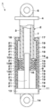
- FIG. 1 is a longitudinal sectional view showing an actuator device (electromagnetic actuator) according to an embodiment
- FIG. FIG. 4 is a cross-sectional view showing a plurality of magnets and a cylinder (magnet cover) according to the first embodiment
- 3 is an enlarged view showing the magnet in FIG. 2 alone
- FIG. It is a cross-sectional view showing assembly steps (1), (2), (3), and (4) in the order of fixing a plurality of magnets to a cylindrical body with an adhesive.
- FIG. 5 is a cross-sectional view showing a plurality of magnets and a cylinder according to a second embodiment
- 6 is an enlarged view showing the magnet in FIG. 5 alone;
- FIG. 11 is a cross-sectional view showing a plurality of magnets and a cylinder according to a third embodiment;
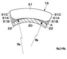
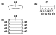
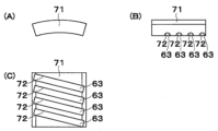
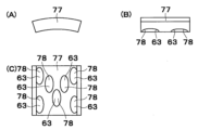
- FIG. 11 is a cross-sectional view showing part of a magnet and a cylinder according to a fourth embodiment; It is the external view which looked at the magnet by 5th Embodiment from three different directions of (A), (B), and (C). It is the external view which looked at the magnet by the 1st modification from three different directions of (A), (B), and (C). It is the external view which looked at the magnet by the 2nd modification from three different directions (A), (B), and (C). It is the external view which looked at the magnet by the 3rd modification from three different directions of (A), (B), and (C).
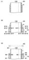
- FIG. 11 is a longitudinal sectional view showing assembly steps (1), (2), and (3) in the order of fixing a magnet and a sheet member to a cylinder with an adhesive according to a fifth modification;
- FIG. 11 is a vertical cross-sectional view showing a sheet member according to a sixth modification together with magnets and cylinders;
- FIG. 17 is a plan view showing the sheet member in FIG. 16 alone;
- FIG. 11 is a longitudinal sectional view showing a sheet member according to a seventh modified example together with magnets and cylinders;
- FIG. 19 is a plan view showing the sheet member in FIG. 18 alone; It is a cross-sectional view which shows the assembly process by a comparative example in order of (1), (2), (3), (4), (5), and (6).
- an electromagnetic actuator 1 as an actuator device is also called an electric linear motor, an electric actuator, or an electric linear actuator.
- the electromagnetic actuator 1 is mounted, for example, on a vehicle such as a railroad vehicle or an automobile, and constitutes an electromagnetic suspension device together with springs (suspension springs, coil springs, air springs) (not shown).
- the electromagnetic actuator 1 is positioned, for example, between a sprung vehicle body and an unsprung wheel, between a sprung vehicle body and an unsprung bogie, or between a spring It is provided together with a spring between the carriage on the upper side and the wheel (axle, wheelset) on the unsprung side.
- a member on the sprung side such as a vehicle body and a bogie is referred to as a "sprung member”.
- unsprung members such as trucks, wheels, axles, and wheel sets are called “unsprung members”.
- the electromagnetic actuator 1 includes, for example, a stator 2 arranged on the upper side of the spring and a mover 11 arranged on the lower side of the spring.
- the electromagnetic actuator 1 includes annular magnets 19, 19 provided on a mover 11 that is a first member (one side member) and an armature 8 provided on a stator 2 that is a second member (other side member).
- the coil member 10 (coils 10A, 10B, 10C) constitutes a three-phase linear motor (three-phase linear synchronous motor).
- the electromagnetic actuator 1 is configured as a cylindrical linear electromagnetic actuator composed of a pair of coaxial cylindrical members that are relatively displaceable. is interposed between
- the electromagnetic actuator 1 includes annular magnets 19, 19 as magnetic members provided in the outer cylinder 12 corresponding to the first cylinder, and the inner cylinder 3 corresponding to the second cylinder via the core member 9. and a coil member 10 (coils 10A, 10B, 10C) composed of a multi-phase coil group.
- the coil member 10 is arranged radially facing the annular magnets 19, 19 over the entire circumference.
- the stator 2 and mover 11 of the electromagnetic actuator 1 are attached between two members that move relatively (for example, between an unsprung member that is one member and a sprung member that is the other member).
- the stator 2 and the mover 11 are arranged between the sprung member and the unsprung member so as to be linearly displaced relative to each other (relative movement).
- a thrust force is generated in the vertical direction in FIG.
- the unsprung member corresponds to the first mounting member
- the sprung member corresponds to the second mounting member. That is, the electromagnetic actuator 1 is provided between a first mounting member (eg, unsprung member) and a second mounting member (eg, sprung member) that relatively move.
- the electromagnetic actuator 1 has a first member fixed to the first mounting member and a second member fixed to the second mounting member.
- the first member and the second member of the electromagnetic actuator 1 the case where the first member is the mover 11 and the second member is the stator 2 is exemplified.
- the invention is not limited to this, and the first member may be the stator and the second member may be the mover. That is, the stator may be fixed to the unsprung member (first mounting member) and the mover may be fixed to the sprung member (second mounting member).
- the first mounting member may be the sprung member, and the second mounting member may be the unsprung member.
- one axial end side of the electromagnetic actuator 1 is defined as the lower end side (lower end side in FIG. 1), and the other axial end side is defined as the upper end side (upper end side in FIG. 1). may be the upper end side, and the other axial end side may be the lower end side.
- the stator 2 of the electromagnetic actuator 1 has an armature 8 on its lower end side, which is one end side. That is, the stator 2 as a second member includes an inner cylinder 3 as a second cylinder, an intermediate cylinder 7, an armature 8, and a first support member 16, which will be described later.
- the inner cylinder 3 as a second cylinder is formed as a tubular member (cylindrical member) extending in the vertical direction (axial direction).
- the intermediate cylinder 7 of the stator 2 and the outer cylinder 12 of the mover 11 are arranged radially outside the inner cylinder 3 .
- the inner cylinder 3 is arranged radially inside the outer cylinder 12 and the intermediate cylinder 7 .
- the inner cylinder 3 is arranged on the inner periphery of the outer cylinder 12 so as to be relatively movable in the axial direction of the outer cylinder 12 .
- An armature 8 is provided at the lower end, which is one end of the inner cylinder 3 .
- the lower end of the inner cylinder 3 extends axially along the inner circumference of the armature 8 (core member 9), and is fixed inside the core member 9 by means of fitting, press-fitting, or the like. That is, the lower end of the inner cylinder 3 extends to the armature 8 and is located on the inner peripheral side of the armature 8 .
- a rod 15 of the mover 11 is inserted into the inner cylinder 3 .
- the upper end which is the other end of the inner cylinder 3, is attached to a sprung member (second attachment member: the other member between the two members).
- the upper end side of the inner cylinder 3 is fixed to the upper plate 4 . That is, the upper end of the inner cylinder 3 extends axially to the position of the upper plate 4 and is closed by the upper plate 4 .
- the inner cylinder 3 is provided inside the outer cylinder 12, the rod 15 is inserted from the lower end side which is one end side, and the upper end side which is the other end side is closed.
- the upper plate 4 is formed in a disc shape and has a larger diameter dimension than the intermediate cylinder 7 .
- the upper plate 4 is provided with an attachment eye 5 attached to, for example, a sprung member (second attachment member) of the vehicle.
- the mounting eye 5 mounts the inner cylinder 3 and the intermediate cylinder 7 together with the upper plate 4 to the sprung member.
- the intermediate cylinder 7 is formed as a tubular (cylindrical) tubular member (cylindrical member) extending in the vertical direction (axial direction).
- the intermediate cylinder 7 is provided on the outer peripheral side of the inner cylinder 3 .
- the upper end of the intermediate cylinder 7 is closed by the upper plate 4 .
- a lower end portion of the intermediate cylinder 7 is connected to the armature 8 .
- the armature 8 is formed in an annular shape.
- the inner cylinder 3 is inserted into the inner peripheral portion (the space on the inner peripheral side) of the armature 8 .
- the armature 8 includes, for example, a substantially cylindrical core member 9 made of a magnetic material, and a plurality of coils 10A, 10B, and 10C (i.e., u-phase coil 10A, v-phase coil 10B and w-phase coil 10C).
- the core member 9 is provided on the lower end side of the inner cylinder 3, that is, on the bottom side of the outer cylinder 12 (bottom plate 13 side).
- the core member 9 has coil members 10, that is, coils 10A, 10B, and 10C, on its outer periphery.
- the coils 10A, 10B, 10C are arranged on the outer circumference of the inner cylinder 3. As shown in FIG. Note that the number of coils 10A, 10B, and 10C is not limited to three, and can be appropriately changed to, for example, six, nine, twelve, etc., according to design specifications and the like.
- a stroke sensor for detecting the stroke amount of the electromagnetic actuator 1 is provided on the outer peripheral side of the lower end of the intermediate cylinder 7 .
- the stroke sensor measures the absolute or relative axial position between the armature 8 and the mover 11 (annular magnets 19, 19).
- the stroke sensor is composed of a magnetic sensor such as a magnetoresistive element or Hall element (Hall IC) that detects magnetic field (magnetic field, magnetic flux) and polarity (magnetic pole) by using changes in magnetoresistance, Hall effect, etc. can be done.
- a magnetic sensor such as a magnetoresistive element or Hall element (Hall IC) that detects magnetic field (magnetic field, magnetic flux) and polarity (magnetic pole) by using changes in magnetoresistance, Hall effect, etc. can be done.
- the stroke sensor detects the magnetic field, polarity, etc. of the annular magnets 19, 19 of the mover 11 displaced in the axial direction with respect to the stroke sensor. Thereby, the axial position (stroke position) of the annular magnets 19, 19 can be calculated, and the necessary current can be supplied to the coils 10A, 10B, 10C of the stator 2 according to this position.
- the stroke sensor is not limited to a magnetic sensor, and various stroke sensors (displacement sensors) capable of measuring the axial relative position or absolute position between the armature 8 and the mover 11, such as a laser displacement meter. ) can be used.
- the lower end of the mover 11 of the electromagnetic actuator 1 is connected to the unsprung member of the vehicle.
- the mover 11 is provided with a magnetic field consisting of a plurality of annular magnets 19 arranged in the axial direction of the mover 11 .
- the mover 11 has an outer cylinder 12 which is a cylindrical member. That is, the mover 11 as the first member includes an outer cylinder 12 as a yoke arranged on the outer peripheral side of the armature 8 (the core member 9 and the coils 10A, 10B, and 10C), and an outer cylinder 12 positioned inside the outer cylinder 12.
- the mover 11 has a bottom plate 13 and a partition member 17 provided at both ends of the outer cylinder 12, respectively.
- the outer cylinder 12 as the first cylinder is made of, for example, a magnetic material that forms a magnetic path when placed in a magnetic field.
- a plurality of annular magnets 19 , 19 are arranged in the axial direction inside the outer cylinder 12 in the radial direction.
- the outer cylinder 12 forms a magnetic circuit of the electromagnetic actuator 1 and also functions as a cover for preventing leakage of the magnetic flux of the annular magnets 19, 19 to the outside.
- the outer cylinder 12 is formed as a tubular (cylindrical) tubular member (cylindrical member) extending in the vertical direction (axial direction).
- the outer cylinder 12 is provided on the outer peripheral side of the inner cylinder 3 and the intermediate cylinder 7 of the stator 2 .
- a lower end portion, which is one end portion of the outer cylinder 12, is attached to an unsprung member (first attachment member: one member between two members).
- first attachment member one member between two members.
- the lower end side of the outer cylinder 12 is fixed to the bottom plate 13 . That is, the lower end of the outer cylinder 12 extends axially to the position of the bottom plate 13 and is closed by the bottom plate 13 .
- the outer cylinder 12 is provided with a bottom plate 13 as a bottom portion on the lower end side, which is one end side, and is open at the upper end side, which is the other end side.
- the bottom plate 13 is formed in a disc shape and has a larger diameter dimension than the inner cylinder 3 of the stator 2 .
- the bottom plate 13 is provided with a mounting eye 14 that is mounted, for example, on an unsprung member of a vehicle.
- a mounting eye 14 mounts the barrel 12 together with the bottom plate 13 to the unsprung member.
- the bottom plate 13 is provided with a rod 15 which is located axially opposite to the mounting eye 14 and extends axially inside the armature 8 from the bottom plate 13 .
- the rod 15 is positioned inside the outer cylinder 12 .
- the rod 15 is inserted into the inner cylinder 3 . That is, the rod 15 extends from the bottom plate 13 through the outer cylinder 12 toward the partition member 17 .
- the rod 15 slides in the inner cylinder 3 via a first support member 16 made of a sliding member such as a sleeve, a bush, or a bearing so as to be relatively displaceable in the axial direction.
- the rod 15 is attached to the bottom plate 13 at its lower end, which is one end.
- the rod 15 has an upper end, which is the other end, extending into the inner peripheral portion of the armature 8 (inner peripheral space), in other words, into the inner cylinder 3 .
- the rod 15 extends from the bottom plate 13, which is the bottom portion of the outer cylinder 12, toward the other open end (upper end) of the outer cylinder 12.
- the rod 15 may be formed integrally with the bottom plate 13, or may be formed separately from the bottom plate 13 and fixed to the bottom plate 13 using screws, bolts, or the like.
- the first support member 16 is positioned, for example, on the outer peripheral side of the rod 15 and provided on the inner peripheral side of the inner cylinder 3 .
- the first support member 16 is attached to the opening on the tip side (lower end side) of the inner cylinder 3 . That is, the first support member 16 is provided on the lower end side, which is one end side of the inner cylinder 3 , and is in sliding contact with the outer peripheral surface of the rod 15 .
- the first support member 16 supports the rod 15 so as to be relatively movable with respect to the inner cylinder 3 . That is, the first support member 16 corresponds to a guide portion that guides the inner cylinder 3 and the armature 8 with respect to the rod 15 . In other words, the first support member 16 corresponds to a closing member that slides on the rod 15 .
- the first support member may be provided on the distal end side of the rod and may be brought into sliding contact with the inner peripheral surface of the inner cylinder.
- the partition member 17 is provided at the upper end which is the other end of the outer cylinder 12 .
- the partition member 17 is formed in an annular shape, and is fixedly attached to the inner peripheral side of the outer cylinder 12 by, for example, screwing or caulking.
- the partition member 17 partitions the outer periphery of the intermediate cylinder 7 from the outside. Further, the partition member 17 prevents the annular magnets 19, 19 from slipping out of the outer cylinder 12, and positions the annular magnets 19, 19 in the axial direction.
- the inner peripheral surface of the partition member 17 is provided with a second support member 18 which is made of a sliding member such as a sleeve, a bush, or a bearing, and is in sliding contact with the outer peripheral surface of the intermediate cylinder 7 .
- the second support member 18 is arranged between the partition member 17 and the stator 2 (intermediate cylinder 7 ), and supports relative movement between the mover 11 and the stator 2 . That is, the second support member 18 constitutes a guide that supports the stator 2 through the intermediate cylinder 7 so as to be slidable in the axial direction.
- a plurality of annular magnets 19 , 19 that serve as field magnets are provided on the mover 11 . That is, the annular magnets 19 , 19 are magnetic members that generate a magnetic field and are arranged in the outer cylinder 12 . In this case, the annular magnets 19, 19 are each formed in an annular shape (cylindrical shape).
- the annular magnets 19, 19 are, for example, an annular magnet integrally formed in an annular (cylindrical) shape, or an annular (cylindrical) magnet formed by arranging a plurality of arc-shaped magnets (divided magnets) in the circumferential direction.
- a structured annular magnet can be employed. As shown in FIG. 2, which will be described later, in the embodiment, the annular magnet 19 is configured by arranging a plurality of arc-shaped magnets 21, 21, which are also called split magnets or segment magnets, on the circumference.
- the annular magnets 19, 19 are arranged side by side along the axial direction on the inner peripheral surface side of the outer cylinder 12.
- the axially adjacent annular magnets 19, 19 have polarities opposite to each other.
- a permanent magnet with an N pole on the inner peripheral side and an S pole on the outer peripheral side a permanent magnet with an S pole on the inner peripheral side and an N pole on the outer peripheral side is arranged next to a permanent magnet with an N pole on the inner peripheral side and an S pole on the outer peripheral side is arranged.
- the number of annular magnets 19, 19 is not limited to the illustrated example. A required number of annular magnets 19, 19 can be arranged according to the stroke amount.
- the electromagnetic actuator 1 is arranged, for example, between the vehicle body and bogie of a railroad vehicle.
- the vehicle body side component of the electromagnetic actuator 1 corresponds to the stator 2 .
- a magnetic core member 9 and coil members 10 (coils 10A, 10B, 10C) formed by winding magnet wires around the core member 9 are arranged on the vehicle body side.
- a bogie-side component of the electromagnetic actuator 1 corresponds to the mover 11 .
- Annular magnets 19, 19 are arranged on the truck side so as to face the armature 8 (coil member 10 and core member 9) on the vehicle body side with a certain air gap therebetween.
- the annular magnets 19, 19 are provided on the inner peripheral side of the outer cylinder 12 made of a magnetic material in the axial direction by the armature length (coil/core length) of the electromagnetic actuator 1 + control stroke length.
- a linear actuator for example, an electromagnetic actuator
- a secondary spring for example, an air spring
- Electromagnetic actuators which are linear actuators, come in two types: one that converts the rotary motion of a rotary motor into a linear motion using a rotary motion conversion mechanism, and the other that uses a linear motor.
- the electromagnetic actuator 1 of FIG. 1 is of a type that uses a linear motor.
- the control force of the electromagnetic actuator is generated by the attractive force and/or the repulsive force between the coil and the magnet. That is, the control force of the electromagnetic actuator is generated by the attractive force and/or the repulsive force between the magnetic flux generated by applying current to the coil and the magnetic flux of the magnet facing the coil.
- the annular magnet 19 can be configured by arranging a plurality of arc-shaped magnets 21, 21 in the circumferential direction.
- the annular magnet 19 may be configured to adhere to the outer peripheral side of the magnet cover 20 with an adhesive.
- the annular magnet 19 (magnets 21 , 21 ) is arranged in the control range of the electromagnetic actuator 1 together with the magnet cover 20 .
- the problem is how to assemble the "outer cylinder 12", the "ring magnet 19 (magnets 21, 21)" and the "magnet cover 20".
- attaching a plurality of arc-shaped magnets 21, 21 that constitute the annular magnet 19 to the inner circumference of the outer cylinder 12 may be extremely labor intensive, because depending on the diameter of the outer cylinder 12, tools and workers may not be required. sexuality worsens. Therefore, a method of attaching the magnets 21, 21 to the outer periphery of the non-magnetic magnet cover 20, forming an assembly of the magnets 21, 21 and the magnet cover 20, and inserting this assembly into the outer cylinder 12 is conceivable.
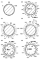
- FIG. 20 is a cross-sectional view showing an assembly process for fixing the arc-shaped magnets 101, 101 to the magnet cover 20 with an adhesive according to the comparative example.
- assembly steps are shown in order of (1), (2), (3), (4), (5), and (6).
- the magnets 101, 101 of the comparative example are not provided with chamfers 21B, 21B unlike the magnet 21 of the first embodiment shown in FIGS. 2 to 4, which will be described later.
- the arc-shaped magnets 101, 101 attached to the magnet cover 20 are both magnetized.
- the adhesive A is applied to the outer peripheral side of the magnet cover 20 .
- the magnets 101, 101 magnetized with the same polarity (N pole or S pole) on the outer peripheral side are placed in the magnet cover before the adhesive A is cured. Paste on the outer peripheral side of 20. At this time, since the magnets 101, 101 attached on the circumference have the same polarity, a repulsive force Fb acts between the magnets 101, 101 adjacent on the circumference.
- a magnetic attraction force Fa acts between the magnets 101 and 101 and the attaching jig 102 .
- the thickness of the attaching jig 102 is designed such that the attraction force Fa is greater than the repulsion force Fb (attraction force Fa>repulsion force Fb).
- the magnets 101 and 101 are held by the attaching jig 102 with the magnet cover 20 interposed therebetween.
- the magnets 101, 101 are arranged side by side with an appropriate gap in the circumferential direction under the influence of the repulsive force Fb generated between the adjacent magnets 101, 101.
- the magnets 101, 101 are shifted in the circumferential direction so as to overcome the repulsive force Fb, and a space for attaching the additional magnet 101 is secured.
- the adhesive A applied to the magnet cover 20 is also displaced together with the magnets 101, 101, and there is a possibility that the adhesive A will be insufficient at the portion where the magnet 101 is attached in the next step. Therefore, in the step (4) following the step (3) in FIG. 20, additional magnets 101 are attached to the portions where the adhesive A is insufficient.
- the restraining force applied to the magnets 101, 101 to secure the space is released.
- the magnets 101, 101 are arranged with an appropriate gap due to the repulsive force Fb generated between the magnets 101, 101 adjacent to each other on the circumference.
- the steps (1) to (5) in FIG. 20 are performed within the usable life of the adhesive.
- the magnets 101, 101 and the magnet cover 20 are left to stand until the adhesive A hardens.
- the sticking jig 102 is removed. That is, after the adhesive between the magnets 101 , 101 and the magnet cover 20 is sufficiently hardened, the sticking jig 102 is pulled out from inside the magnet cover 20 .
- the adhesive force Fd between the magnet 101 and the magnet cover 20 attached to the empty space in the step (4) of FIG. Consider the case where is also small.
- the magnet 101 may come off or peel off from the magnet cover 20, as indicated by a two-dot chain line in FIG. 20(6).
- the magnet 101 separated from the magnet cover 20 rotates due to, for example, the repulsive force of the adjacent magnets 101, 101, and attracts the magnet 101 due to the attractive force of one of the magnets 101.
- an adhesive pool is provided between the magnet cover and the magnet so that the magnet can be prevented from peeling off from the magnet cover after the adhesive hardens and the attaching jig is removed. This is intended to improve the adhesive strength of the magnet. This point will be described below with reference to FIGS. 2 to 4 in addition to FIG.
- the electromagnetic actuator 1 has a mover 11 as a first member and a stator 2 as a second member.
- the mover 11 includes a cylindrical magnet cover 20 arranged inside the outer cylinder 12 and a plurality of magnets 21 and 21 fixed to the magnet cover 20 .
- the magnet 21 is configured as an arcuate curved member, such as a cylindrical member divided into eight in the circumferential direction. Therefore, the annular magnet 19 can be constructed by arranging eight magnets 21 in the circumferential direction.
- the case where the annular magnet 19 is composed of eight magnets 21, that is, the case of eight divisions is taken as an example.
- the number is not limited to this, and may be more or less than eight.
- the plurality of magnets 21 and 21 constitute the annular magnet 19 by being arranged side by side in the circumferential direction on the outer peripheral side of the magnet cover 20 .
- the plurality of annular magnets 19 (magnets 21 , 21 ) are arranged side by side in the axial direction on the outer peripheral side of the magnet cover 20 .
- the magnet 21 has a curved concave inner peripheral surface on the side (inside in the radial direction) that is adhered to the outer peripheral surface of the magnet cover 20 , and this inner peripheral surface corresponds to the contact portion with the magnet cover 20 . do.
- the inner diameter of the inner peripheral surface of the magnet 21 is substantially the same as the outer diameter of the outer peripheral surface of the magnet cover 20 .
- the outer diameter side of the magnet 21 forms a convex outer peripheral surface facing the inner peripheral surface of the mover 11 (outer cylinder 12). As shown in FIGS. 2 and 3, both ends of the magnet cover 20 in the axial direction are generally fan-shaped end faces.
- the plurality of magnets 21 are coated with the adhesive A on the outer side in the circumferential direction of the contact portion with the magnet cover 20 .
- the plurality of magnets 21 has a first adhesive accommodation portion 22 that allows the adhesive A to be accommodated.
- the first adhesive containing portion 22 is formed by chamfers 21B, 21B located radially inward of the circumferential end faces 21A, 21A of the magnet 21 .
- the chamfers 21B, 21B are flat surfaces extending in the axial direction of the magnet 21.
- the chamfers 21B, 21B forming the first adhesive container 22 are larger than the other chamfers 21C, 21C located radially outside the chamfers 21B, 21B.
- chamfers 21B and 21B are provided on both circumferential direction end faces 21A and 21A of the magnet 21 so as to be positioned radially inward, that is, on the magnet cover 20 side.
- the chamfers 21B, 21B form the first adhesive container 22.
- the chamfer 21B of the one circumferential end face 21A of the magnet 21 and the chamfer 21B of the other circumferential end face 21A of the magnet 21 have, for example, the same size.
- chamfers 21C, 21C are provided on the outer side in the radial direction, that is, on the outer cylinder 12 side.
- Another chamfer 21C of the one circumferential end face 21A of the magnet 21 and another chamfer 21C of the other circumferential end face 21A of the magnet 21 have, for example, the same size.
- the radially inner chamfers 21B, 21B are larger than the radially outer chamfers 21C, 21C.
- W1 is larger than W2 (W1>W2).
- W1 is larger than W2 (W1>W2).
- the amount of adhesive that can be accommodated in the first adhesive containing portion 22 is ensured by enlarging the chamfers 21B, 21B forming the first adhesive containing portion 22 .
- the magnet 21 has the chamfers 21B, 21B extending in the axial direction on the inner diameter side.
- 1 adhesive container 22 is provided.
- the first adhesive containing portion 22 is positioned on the inner diameter side of the magnet 21 and on the circumferential outer side (circumferential end surface side) of the magnet 21 from the contact portion with the magnet cover 20 .
- the first adhesive containing portion 22 may have any structure as long as the adhesive A is accumulated therein, and instead of being chamfered, for example, it may have an R shape (convex curved surface). In other words, as long as the first adhesive container 22 has a structure in which the adhesive A is accumulated between the magnet cover 20 and the magnet 21, it is not limited to the chamfered or rounded shape, and any shape or size is acceptable.
- FIG. 4 is a cross-sectional view showing an assembly process when fixing the magnets 21, 21 to the magnet cover 20 with the adhesive A according to the first embodiment.
- the assembly steps are shown in order of (1), (2), (3), and (4).
- the arc-shaped magnets 21, 21 attached to the magnet cover 20 are both magnetized.
- the attaching jig 102 is inserted into the inner peripheral side of the magnet cover 20, the adhesive A is applied to the outer peripheral surface of the magnet cover 20, and the magnets 21, 21 are attached to the outer peripheral surface. wear. This point is the same as the steps (1) and (2) in FIG.
- the magnets 21, 21 are shifted in the circumferential direction to secure a space for attaching an additional magnet 21.
- the first adhesive accommodating portion 22 serving as an adhesive reservoir is provided on the attachment surface side of the magnet 21 on the magnet cover 20 side, more adhesive A than in the comparative example is distributed in the circumferential direction. accumulated between the magnets 21, 21 adjacent to each other.
- step (3) following the step (2) in FIG. 4 when attaching the additional magnet 21 to the empty space, an adhesive A is applied to the side of the additional magnet 21 (the contact portion side with the magnet cover 20). is applied, and the magnet 21 is attached to the magnet cover 20 .
- the restraining force applied to the magnets 21, 21 to secure the space is released. That is, in the step (4) following the step (3) in FIG. 4, the binding force for securing the sticking space is released.
- the magnets 21, 21 that have been constrained are arranged with an appropriate gap maintained by the repulsive force Fb generated between the magnets 21, 21 adjacent on the circumference.
- the first adhesive accommodating portion 22, which serves as a magnet reservoir on the attachment surface side of the magnets 21, 21, contains more adhesive than the comparative example. Accumulates A. Thereby, the adhesive force between the magnets 21, 21 and the magnet cover 20 can be improved. Furthermore, when the magnets 21 and 21 are shifted on the circumference, the adhesive A between the magnets 21 and 21 adjacent in the circumferential direction spreads between the inner circumference side of the magnets 21 and 21 and the outer circumference side of the magnet cover 20. The adhesive force between the adjacent magnets 21, 21 can be improved by accumulating in the first adhesive accommodating portion 22 between them.
- the adhesive force of all the magnets 21, 21 attached to the outer peripheral side of the magnet cover 20 can be improved.
- the electromagnetic actuator 1 has the configuration as described above, and its operation will be described next.
- the electromagnetic actuator 1 constitutes an electromagnetic suspension device for a vehicle together with a spring (not shown).
- the electromagnetic suspension device can be interposed vertically between a sprung member (vehicle side) and an unsprung member (wheel side) of a vehicle.
- the electromagnetic suspension device can be interposed in the lateral direction between the sprung member (on the vehicle body side) and the unsprung member (on the bogie side) of the vehicle.
- force acts on the electromagnetic suspension device in the stroke direction (axial direction).
- the vehicle is placed horizontally, when the vehicle vibrates in the left-right direction, force acts on the electromagnetic suspension device in the stroke direction (axial direction).
- the stator 2 and mover 11 of the electromagnetic actuator 1 move relative to each other.
- the electromagnetic actuator 1 applies a predetermined current to the coils 10A, 10B, and 10C in accordance with the magnetic pole positions of the coils 10A, 10B, and 10C and the ring magnets 19 and 19, thereby generating thrust (damping force) of the electromagnetic actuator 1. ) can be adjusted. As a result, the ride comfort and steering stability of the vehicle can be improved.
- the magnets 21, 21 are coated with the adhesive A on the outer side in the circumferential direction of the contact portion with the magnet cover 20, and the adhesive A can be accommodated. It has a first adhesive container 22 .
- the magnets 21 and 21 and the magnet cover 20 are bonded together by the adhesive A applied to the outer side in the circumferential direction of the contact portion with the magnet cover 20 and the adhesive A contained in the first adhesive containing portion 22 . It can improve the adhesive strength with In this case, the adhesive strength between the magnets 21, 21 and the magnet cover 20 and between the magnets 21, 21 adjacent in the circumferential direction can be improved.
- the first adhesive container 22 is formed by chamfers 21B, 21B located radially inside the circumferential end faces 21A, 21A of the magnet 21 . Therefore, the space defined by the outer peripheral surface of the magnet cover 20 and the chamfers 21B, 21B of the magnet 21 can be used as the first adhesive containing portion 22, and the adhesive A can be contained in this space. Moreover, the chamfers 21B, 21B of the first adhesive containing portion 22 are larger than the other chamfers 21C, 21C located radially outside the chamfers 21B, 21B. Therefore, the amount of adhesive A that can be accommodated in the first adhesive accommodating portion 22 can be increased.
- the magnet 21 of the first embodiment has the first adhesive accommodating portion 22 that serves as an adhesive reservoir on the outer side in the circumferential direction of the attachment surface (contact portion) of the magnet 21 .
- the first adhesive container 22 can store the adhesive A during the step (2) of FIG. 4, that is, when the magnets 21, 21 are shifted in the circumferential direction. Thereby, the adhesive strength between the magnets 21, 21 and the magnet cover 20 and between the magnets 21, 21 adjacent in the circumferential direction can be improved.
- FIGS. 5 and 6 show a second embodiment.
- a feature of the second embodiment is that the inner diameter of the magnet is smaller than the outer diameter of the cylindrical body (magnet cover).
- symbol shall be attached
- the magnet 31 of the second embodiment is provided with chamfers 31B, 31B radially inward of the circumferential end surfaces 31A, 31A, similarly to the magnet 21 of the first embodiment.
- the chamfers 31B, 31B form a first adhesive containing portion 22 that allows the adhesive A to be contained.
- the chamfers 31B, 31B forming the first adhesive containing portion 22 are larger than the other chamfers 31C, 31C located radially outside the chamfers 31B, 31B.
- the first adhesive containing portion 22 is positioned on the inner diameter side of the magnet 31 and on the circumferential outer side (circumferential end surface side) of the magnet 31 from the contact portion with the magnet cover 20 .
- the magnet 31 of the second embodiment has another first adhesive containing portion 32 in addition to the first adhesive containing portion 22 .
- Another first adhesive containing portion 32 is located on the inner diameter side of the magnet 31 and further inside (center side) in the circumferential direction of the magnet 31 than the contact portion with the magnet cover 20 .
- the magnet 31 has an inner diameter Ra of the inner peripheral surface smaller than an outer diameter Rb of the outer peripheral surface of the magnet cover 20 (Ra ⁇ Rb).
- another first adhesive container 32 is formed between the outer peripheral surface of the magnet cover 20 and the inner peripheral surface of the magnet 31 .
- the magnet does not have the first adhesive accommodating portion located on the end surface side in the circumferential direction, and has only another first adhesive accommodating portion located on the center side in the circumferential direction. good too.
- the magnet 31 as described above is fixed to the magnet cover 20 with the adhesive A, and its basic action is not particularly different from that of the first embodiment described above. That is, in the second embodiment, as in the first embodiment, the magnets 31, 31A, 31A are held together by the adhesive A contained in the first adhesive containing portion 22 located on the side of the circumferential end faces 31A, 31A of the magnet 31. The bonding strength between 31 and magnet cover 20 can be improved. In addition, in the second embodiment, the magnets 31 , 31 and the magnet cover 20 are bonded together by the adhesive A contained in another first adhesive containing portion 32 located on the center side in the circumferential direction of the magnet 31 .
- the magnet 31 of the second embodiment has the inner peripheral surface that serves as the attachment surface as another first adhesive containing portion 32 that serves as an adhesive reservoir.
- Another first adhesive container 32 stores the adhesive A when the magnet 31 is attached radially inward from the outer diameter side of the magnet cover 20 and when the magnet 31 is displaced in the circumferential direction. can be done. Thereby, the bonding strength between the magnet 31 and the magnet cover 20 can be further improved.
- FIG. 7 shows a third embodiment.
- the feature of the third embodiment is that the inner diameter of the magnet is larger than the outer diameter of the cylindrical body (magnet cover), and the inner peripheral surface of the magnet and the outer peripheral surface of the cylindrical body (magnet cover) are glued together. There is a thickness separation.
- symbol shall be attached
- the magnet 41 of the third embodiment also has chamfers 41B on the radially inner side of the circumferential end faces 41A, 41A, and another chamfered on the radially outer side. 41C, 41C are provided.
- the chamfers 41B, 41B form a first adhesive containing portion 22 that allows the adhesive A to be contained.
- the magnet 41 as described above is fixed to the magnet cover 20 with the adhesive A, and its basic action is not particularly different from that of the first embodiment described above. That is, in the third embodiment, similarly to the first embodiment, the bonding strength between the magnets 41 and 41 and the magnet cover 20 can be improved by the adhesive A contained in the first adhesive containing portion 22 . In addition to this, in the third embodiment, the bonding strength between the magnets 41, 41 and the magnet cover 20 is increased by the adhesive A contained between the outer peripheral surface of the magnet cover 20 and the inner peripheral surface of the magnet 41. can improve.
- FIG. 8 shows a fourth embodiment.
- the feature of the fourth embodiment is that the inner diameter of the magnet is larger than the outer diameter of the cylinder (magnet cover), and the center of the inner peripheral surface of the magnet is brought into contact with the outer peripheral surface of the cylinder (magnet cover). It's because I let him come in contact with me.
- symbol shall be attached
- the magnet 51 of the fourth embodiment is also provided with chamfers 51B, 51B on the radially inner side of the circumferential end faces 51A, 51A, and another chamfered on the radially outer side. 51C, 51C are provided.
- the chamfers 51B, 51B form a first adhesive containing portion 22 that allows the adhesive A to be contained.
- the inner diameter dimension Ra of the inner peripheral surface is made larger than the outer diameter dimension Rb of the outer peripheral surface of the magnet cover 20, similarly to the magnet 41 of the third embodiment ( Ra>Rb). In this case, in the fourth embodiment, the central portion of the inner peripheral surface of the magnet 51 is brought into contact with the outer peripheral surface of the magnet cover 20 .
- the magnet 51 as described above is fixed to the magnet cover 20 with the adhesive A, and its basic action is not particularly different from that of the first embodiment described above. That is, in the fourth embodiment as well, the bonding strength between the magnets 51, 51 and the magnet cover 20 can be improved by the adhesive A contained in the first adhesive containing portion 22, as in the first embodiment. In addition to this, in the fourth embodiment, the magnets 51 and 51 and the magnet cover 20 are bonded together by the adhesive A contained in the wedge-shaped space between the inner peripheral surface of the magnet 51 and the outer peripheral surface of the magnet cover 20 . It can improve the adhesive strength with
- the inner diameter Ra of the inner peripheral surface of the magnet and the outer diameter Rb of the outer peripheral surface of the cylindrical body (magnet cover) may be “Ra ⁇ Rb”. However, it may be "Ra ⁇ Rb" or “Ra>Rb”.
- FIG. 9 shows a fifth embodiment.
- the first adhesive containing portion is formed by a groove portion provided in the contact portion of the magnet.
- symbol shall be attached
- the magnet 61 of the fifth embodiment is not provided with chamfers 21B, 21B like the magnet 21 of the first embodiment.
- a magnet 61 of the fifth embodiment is provided with grooves 62, 62 on its inner peripheral surface. That is, a plurality of (for example, four) grooves 62 , 62 are provided on the inner peripheral surface of the magnet 61 .
- the groove portion 62 is recessed radially outward from the inner peripheral surface of the magnet 61 and extends in the circumferential direction of the magnet 61 .
- the cross section of the groove portion 62 is semicircular.
- the groove portion 62 forms a first adhesive containing portion 63 that contains the adhesive A. As shown in FIG. That is, the first adhesive containing portion 63 is formed by a groove portion 62 provided in at least a portion of the inner peripheral surface of the magnet 61 (in other words, the contact portion with the magnet cover 20).
- the magnet 61 as described above is fixed to the magnet cover 20 with the adhesive A, and its basic function is not particularly different from that of the first embodiment described above. That is, in the fifth embodiment as well, the bonding strength between the magnets 61 and 61 and the magnet cover 20 can be improved by the adhesive A contained in the first adhesive containing portion 63 .
- the first adhesive containing portion 63 is formed by a groove portion 62 provided on the inner peripheral surface of the magnet 61 , that is, the contact portion with the magnet cover 20 . Therefore, the space defined by the outer peripheral surface of the magnet cover 20 and the inner surface of the groove portion 62 can be used as the first adhesive containing portion 63, and the adhesive A can be contained in this space.
- the first adhesive containing portion 63 serving as an adhesive reservoir is provided on the contact surface between the magnet 61 and the magnet cover 20 . That is, a groove portion 62 serving as a concave portion for holding an adhesive is provided on the surface where the magnet 61 and the magnet cover 20 are in contact with each other. This allows the adhesive A to accumulate when the magnet 61 is displaced on the magnet cover 20 in the circumferential direction. That is, the groove portion 62 forming the first adhesive containing portion 63 is provided on the surface where the magnet 61 and the magnet cover 20 contact, more specifically, on the inner peripheral surface (contact portion) of the magnet 61 . .
- the groove portion 62 extends in a direction perpendicular to the axial direction of the magnet 61 , that is, in the circumferential direction of the magnet 61 . In this case, the groove portion 62 extends over the entire circumference of the contact surface with the magnet cover 20 .
- the adhesive A enters the groove portion 62 serving as the first adhesive accommodating portion 63, and the magnet 61 and the magnet cover 20 are separated from each other. (that is, inside the groove portion 62). Further, even when the magnet 61 is displaced on the magnet cover 20 in the circumferential direction, the adhesive A can be kept in the groove 62 . As a result, more adhesive A can be accumulated between the magnet 61 and the magnet cover 20, and the adhesive force can be further improved.
- one magnet 61 is provided with a plurality (four) of grooves 62, but the number of grooves 62 may be singular (1) or plural (2 or more), and the number does not matter. .
- the groove portion 62 extends in the direction perpendicular to the axial direction of the magnet 61 (that is, the circumferential direction of the magnet 61) has been described as an example.
- the present invention is not limited to this, and for example, the groove portion 72 may be inclined with respect to the circumferential direction of the magnet 71 as in the first modification shown in FIG.
- the number of grooves 72 may be singular (1) or plural (2 or more), and the number does not matter.
- the groove portion 62 extends continuously from one end side to the other end side in the circumferential direction.
- the present invention is not limited to this, and grooves 74 may be provided intermittently in the circumferential direction of magnets 73 as in a second modification shown in FIG. 11, for example. That is, the groove portion 74 may be separately provided on one end side and the other end side in the circumferential direction. Further, for example, as in a third modified example shown in FIG. can be tilted.
- the magnets 73 and 75 are moved twice in the circumferential direction when the magnets 73 and 75 are attached to the magnet cover 20. Focusing on That is, the first movement is to displace the magnets in the circumferential direction to make room for the additional magnets. In the second movement, after the magnet is displaced in the circumferential direction, the restraining force applied to the magnet is released, and the magnet returns in the circumferential direction due to the repulsive force of the magnet. In the first and second times, the magnet moves in opposite directions in the circumferential direction.
- grooves 74 and 76 serving as adhesive reservoirs are provided on both sides of the magnets 73 and 75 in the circumferential direction. Adhesive can accumulate between the magnets 73 , 75 and the magnet cover 20 .
- the grooves 74 and 76 are separately provided on one end side and the other end side of the magnets 73 and 75 in the circumferential direction, the ratio of the grooves 74 and 76 to the entire magnets 73 and 75 can be reduced. can. Thereby, deterioration of the performance of the magnets 73 and 75 due to the provision of the grooves 74 and 76 can be suppressed.
- one magnet 73, 75 is provided with a plurality of sets (for example, four sets) of grooves 74, 76 on one end side and the other end side in the circumferential direction.
- sets for example, four sets
- the groove may be provided only on one of the one end side and the other end side in the circumferential direction.
- the groove portion 62 extends continuously from one end side to the other end side in the circumferential direction.
- a plurality of (for example, seven) grooves 78 may be randomly provided on the inner peripheral surface of the magnet 77 as in a fourth modification shown in FIG. 13 .
- the groove portion 78 may be a curved concave portion.
- the magnet 77 can be manufactured at low cost. Since the magnet is a sintered product, it is put into a mold and pressed. For this reason, the groove portion that serves as an adhesive reservoir for the magnet can be molded without additional processing steps by incorporating it at the stage of the press mold.
- the magnet can be manufactured at low cost by forming the groove (adhesive reservoir) into a concave shape in consideration of the press direction, the life of the mold, and the like.
- the groove adheresive reservoir
- one magnet 77 is provided with a plurality of grooves 78, but the number of grooves 72 may be singular (1) or plural (2 or more), and the number does not matter.
- the case where the magnet 21 is provided with the chamfers 21B, 21B so that the first adhesive containing portion 22 is provided between the magnet 21 and the magnet cover 20 has been described as an example.
- a groove portion 81E and a chamfer 81F forming the second adhesive containing portion 82 may be provided on the axial end surfaces 81D, 81D of the 81 .
- the magnet 81 of the fifth modification is provided with chamfers 81B, 81B on the radially inner side of the circumferential end faces 81A, 81A, and other chamfers 81C, 81C on the radially outer side.
- the magnet 81 is provided with grooves 81E extending in the circumferential direction and chamfers 81F on the axial end faces 81D, 81D.
- the groove portion 81E curves and extends along the outer peripheral surface of the magnet 81, and has a semicircular cross section. Further, the chamfer 81F is located on the inner diameter side of the groove 81E and extends in a curved manner along the inner peripheral surface of the magnet 81. As shown in FIG. The groove 81E and the chamfer 81F form the second adhesive containing portion 82. As shown in FIG. That is, the plurality of magnets 81 that constitute the annular magnet 19 have second adhesive containing portions 82 that can contain the adhesive A on at least part of the axial end faces 81D, 81D.
- the plurality of magnets 81 constitute the annular magnet 19 by arranging them in the circumferential direction.
- the annular magnets 19 are arranged side by side in the axial direction of the electromagnetic actuator 1, as shown in FIG.
- the axially adjacent annular magnets 19 are magnetized with different polarities, and a strong attractive force acts between the axially adjacent annular magnets 19 . Therefore, in the fifth modification, as shown in FIG. 15, a sheet member 83 serving as a non-magnetic spacer is provided between the axially adjacent annular magnets 19 (magnets 81, 81).
- annular sheet members 83 are provided on the axial end faces 81D, 81D of the magnet 81.
- the mover 11 as the first member has an annular sheet member 83 provided between the magnets 81 adjacent in the axial direction.
- the groove portion 81E and the chamfered portion 81F forming the second adhesive containing portion 82 face the side surface of the sheet member 83.
- the chamfer 81 ⁇ /b>F forming the second adhesive containing portion 82 faces the outer peripheral surface of the magnet cover 20 in addition to facing the side surface of the sheet member 83 .
- FIG. 15 shows an assembly process when fixing the magnet 81 and the sheet member 83 to the magnet cover 20 with the adhesive A according to the fifth modification.
- assembly steps are shown in the order of (1), (2), and (3).
- the attaching jig 102 is inserted into the inner peripheral side of the magnet cover 20 and the adhesive A is applied to the outer peripheral surface of the magnet cover 20 .
- step (2) following step (1) in FIG. The process up to this point is the same as the process in FIG.
- step (3) following step (2) in FIG. 15 sheet member 83 is assembled to magnet cover 20 .
- the adhesive A on the outer peripheral side of the magnet cover 20 is scraped off by the sheet member 83, but this adhesive A accumulates in the grooves 81E and the chamfers 81F forming the second adhesive accommodating portion 82 of the magnets 81, 81. .
- the adhesive force between the magnets 81, 81 and the magnet cover 20 and the adhesive force between the magnets 81, 81 and the sheet member 83 can be improved.
- the axial end face 81D of the magnet 81 is provided with the second adhesive containing portion 82 that serves as an adhesive reservoir. Therefore, the adhesive A contained in the second adhesive containing portion 82 can improve the adhesive strength between the magnet 81 and the sheet member 83 that are axially adjacent to each other. In addition, in the case where the sheet member is not provided, the adhesive contained in the second adhesive containing portion can improve the adhesive strength of the magnets adjacent to each other in the axial direction.
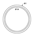
- the sheet member 91 may be provided with a third adhesive containing portion 92 capable of containing the adhesive A.
- the mover 11 similarly to the fifth modification, has an annular sheet member 91 provided between the magnets 21 adjacent in the axial direction.
- the sheet member 91 has a third adhesive containing portion 92 capable of containing the adhesive A on at least part of the surface facing the magnet cover 20 .
- the third adhesive container 92 serving as an adhesive reservoir is provided on the side surface of the sheet member 91 and on the inner diameter side of the sheet member 91 .
- chamfers 91A are provided along the entire circumference on both axial side surfaces of the sheet member 91 on the inner side in the radial direction. 91 A of chamfers form the 3rd adhesive agent accommodating part 92.
- FIG. 10 when the sheet member 91 is attached to the magnet cover 20 after the magnets 21 are attached to the magnet cover 20, the adhesive A on the outer peripheral surface of the magnet cover 20 is bonded to the magnets 21 and the magnets. It can be accumulated in the third adhesive container 92 between the cover 20 and the sheet member 91 . Thereby, the bonding strength between the magnet 21, the magnet cover 20 and the sheet member 91 can be improved.
- the sheet member 91 is provided with the third adhesive accommodating portion 92 that serves as an adhesive reservoir between the magnet 21 and the sheet member 91 . Therefore, when the magnet 21 is displaced along the circumference, the adhesive A accumulates in the third adhesive accommodating portion 92 of the sheet member 91, thereby improving the adhesive strength between the magnet 21, the sheet member 91, and the magnet cover 20. can. That is, the adhesive A contained in the third adhesive containing portion 92 adheres between the magnet 21 and the sheet member 91, between the magnet 21 and the magnet cover 20, and between the sheet member 91 and the magnet cover 20. Can improve strength.
- the sheet member is chamfered to provide the third adhesive containing portion.
- a chamfer 91A is provided on the inner diameter side of the sheet member 91 over the entire circumference, thereby accommodating the third adhesive between the magnet 21, the sheet member 91 and the magnet cover 20.
- the case of the configuration having the portion 92 has been described as an example. However, not limited to this, for example, as in a seventh modification shown in FIGS. and the sheet member 91 and the magnet cover 20 may be configured to have a third adhesive containing portion 92 .
- the notch 93 is recessed in a semicircular shape from the inner peripheral surface of the sheet member 91 toward the outside in the radial direction.
- the third adhesive containing portion 92 is formed by a notch portion 93 that cuts the inner peripheral surface of the sheet member 91 . Therefore, the space defined by the notch 93 and the axial end surface of the magnet 21 and the outer peripheral surface of the magnet cover 20, which face the notch 93, can be used as the third adhesive container 92.
- the adhesive A can be accommodated in this space.
- the third adhesive containing portion 92 is provided on the inner diameter side of the sheet member 91, that is, the surface of the side facing the magnet cover 20 is taken as an example.
- the present invention is not limited to this, and for example, the third adhesive container may be provided on the outer diameter side of the sheet member, that is, on the surface facing the first cylinder (outer cylinder). Also, the third adhesive container may be provided on both the inner diameter side and the outer diameter side of the sheet member. The same applies to the first to fifth embodiments and the first to fifth modifications in which the sheet member is provided with the third adhesive container.
- a notch 93 forming a third adhesive containing portion 92 is provided on the inner diameter side of the sheet member 91, that is, on the inner peripheral surface facing the magnet cover 20.
- the notch may be provided on the outer diameter side of the sheet member, that is, on the outer peripheral surface facing the first cylinder (outer cylinder).
- the notch portion may be provided on both the inner diameter side (inner peripheral surface) and the outer diameter side (outer peripheral surface) of the sheet member. The same applies to the first to fifth embodiments and the first to fifth modifications in which cutouts are provided in the sheet member.
- the sheet member 91 is provided with the third adhesive containing portion 92, and the magnet 21 is provided with the second adhesive containing portion.
- the present invention is not limited to this, and for example, the sheet member may be provided with the third adhesive accommodating portion and the magnet may be provided with the second adhesive accommodating portion.
- the case where the chamfer 21B is provided radially inward of the circumferential end surface 21A of the magnet 21 and another chamfer 21C is provided radially outward has been described as an example. However, it is not limited to this, and for example, it is not necessary to provide another chamfer on the radially outer side. That is, a separate chamfer may be omitted. This also applies to the first to fourth embodiments and the fifth to seventh modifications.
- the configuration in which the first adhesive containing portion 22 is provided on the outer side in the circumferential direction of the attachment surface (abutting portion) of the magnet 21 has been described as an example.
- the configuration is not limited to this, and for example, both the first adhesive containing portion 22 as in the first embodiment and the first adhesive containing portion 63 as in the fifth embodiment may be provided.
- the magnet may be configured such that the first adhesive containing portions are provided at the "abutting portion of the cylindrical body (magnet cover)" and "the outer side of the abutting portion in the circumferential direction".
- the first adhesive containing portion provided in the contact portion not only the first adhesive containing portion 63 as in the fifth embodiment, but also the first to fourth modified examples, for example, You may employ
- the stator 2 is configured to include the intermediate cylinder 7
- the present invention is not limited to this and, for example, the intermediate cylinder may be omitted.
- the inner peripheral side of the partition member can be made to closely face the inner cylinder as the second cylinder, and the second support member can be provided between the partition member and the inner cylinder. This also applies to the second to fifth embodiments and the first to seventh modifications.
- the cylindrical linear electromagnetic actuator is composed of coils 10A, 10B, and 10C (coil member 10) provided on the core member 9 on the stator 2 side and the outer cylinder 12 on the mover 11 side.
- coils 10A, 10B, and 10C coil member 10
- the case where it is configured by the annular magnets 19, 19 (magnetic members) provided in the above has been described as an example.
- a cylindrical linear electromagnetic actuator may be configured by a coil (coil member) provided on the mover side and a permanent magnet (magnetic member) provided on the stator side. .
- stator 2 is attached to the sprung member of the vehicle and the mover 11 is attached to the unsprung member of the vehicle has been described as an example.
- stator may be attached to the unsprung member of the vehicle, and the mover may be attached to the sprung member of the vehicle.
- the electromagnetic actuator 1 is attached to a vehicle. You may use it as buffers, such as.
- the electromagnetic actuator is not limited to shock absorbers, and can be used as actuators (driving devices) for driving various devices.
- the magnet has the adhesive applied to the outer side in the circumferential direction of the contact portion with the cylinder, and has the first adhesive accommodating portion capable of accommodating the adhesive. are doing. Therefore, the bonding strength between the magnet and the cylinder can be improved by the adhesive applied to the outer side in the circumferential direction of the contact portion with the cylinder and the adhesive contained in the first adhesive container. In this case, it is possible to improve the adhesive strength between the magnet and the cylindrical body and between the circumferentially adjacent magnets.
- the first adhesive containing portion is formed by chamfering positioned radially inward of the circumferential end surface of the magnet. Therefore, the space defined by the "outer peripheral surface of the cylindrical body" and the “chamfering of the magnet” can be used as the first adhesive containing portion, and the adhesive can be contained in this space. Moreover, the chamfer of the first adhesive container is larger than the other chamfer located radially outside of this chamfer. Therefore, the amount of adhesive that can be accommodated in the first adhesive accommodating portion can be increased.
- the first adhesive containing portion is formed by a groove provided in at least part of the contact portion. Therefore, the space defined by the "outer peripheral surface of the cylindrical body" and the “inner surface of the groove” can be used as the first adhesive containing portion, and the adhesive can be contained in this space.
- the magnet has a second adhesive accommodating portion capable of accommodating an adhesive on at least part of the axial end face. Therefore, the adhesive contained in the second adhesive containing portion can improve the adhesive strength of the magnets adjacent to each other in the axial direction. Further, for example, in the case where an annular sheet member is provided between the magnets adjacent in the axial direction, the adhesive contained in the second adhesive containing portion causes the magnets and the sheet member adjacent in the axial direction to adhere to each other. It can improve the adhesion strength between
- the annular sheet member provided between the axially adjacent magnets has a third adhesive that can accommodate an adhesive on at least part of the surface facing the first cylinder or cylindrical body. It has a storage section. Therefore, the adhesive contained in the third adhesive containing portion can improve the adhesive strength between the magnet and the first cylinder or cylindrical body. In this case, the adhesive strength between the sheet member and the magnet and between the sheet member and the first cylinder or cylindrical body can be improved.
- the third adhesive containing portion is formed by a cutout portion that cuts out the inner peripheral surface or the outer peripheral surface of the sheet member. Therefore, the space defined by the "notch” and “the surface facing the notch” can be used as the third adhesive container, and the adhesive can be contained in this space.
- the present invention is not limited to the above-described embodiments, and includes various modifications.
- the above-described embodiments have been described in detail in order to explain the present invention in an easy-to-understand manner, and are not necessarily limited to those having all the configurations described.
- part of the configuration of one embodiment can be replaced with the configuration of another embodiment, and the configuration of another embodiment can be added to the configuration of one embodiment.
- 1 electromagnetic actuator (actuator device), 2: stator (second member), 3: inner cylinder (second cylinder), 9: core member, 10: coil member, 10A, 10B, 10C: coil, 11: movable child (first member), 12: outer cylinder (first cylinder), 13: bottom plate (bottom), 15: rod, 19: annular magnet, 20: magnet cover (cylinder), 21, 31, 41, 51 , 61, 71, 73, 75, 77, 81: magnets, 21A, 31A, 41A, 51A, 81A: circumferential end faces, 21B, 31B, 41B, 51B, 81B: chamfers, 21C, 31C, 41C, 51C, 81C : another chamfer, 22, 63: first adhesive accommodating part, 32: another first adhesive accommodating part, 62, 72, 74, 76, 78: groove part, 81D: axial end surface, 82: second adhesion Agent accommodating portion 83, 91: sheet member 92: third adhesive accommodating portion 93:
Landscapes
- Engineering & Computer Science (AREA)
- Physics & Mathematics (AREA)
- General Engineering & Computer Science (AREA)
- Electromagnetism (AREA)
- Acoustics & Sound (AREA)
- Aviation & Aerospace Engineering (AREA)
- Mechanical Engineering (AREA)
- Chemical & Material Sciences (AREA)
- Combustion & Propulsion (AREA)
- Power Engineering (AREA)
- Linear Motors (AREA)
Priority Applications (1)
| Application Number | Priority Date | Filing Date | Title |
|---|---|---|---|
| JP2023556171A JPWO2023074145A1 (https=) | 2021-10-26 | 2022-09-09 |
Applications Claiming Priority (2)
| Application Number | Priority Date | Filing Date | Title |
|---|---|---|---|
| JP2021-174765 | 2021-10-26 | ||
| JP2021174765 | 2021-10-26 |
Publications (1)
| Publication Number | Publication Date |
|---|---|
| WO2023074145A1 true WO2023074145A1 (ja) | 2023-05-04 |
Family
ID=86157750
Family Applications (1)
| Application Number | Title | Priority Date | Filing Date |
|---|---|---|---|
| PCT/JP2022/033824 Ceased WO2023074145A1 (ja) | 2021-10-26 | 2022-09-09 | アクチュエータ装置 |
Country Status (2)
| Country | Link |
|---|---|
| JP (1) | JPWO2023074145A1 (https=) |
| WO (1) | WO2023074145A1 (https=) |
Cited By (2)
| Publication number | Priority date | Publication date | Assignee | Title |
|---|---|---|---|---|
| CN117662677A (zh) * | 2023-05-31 | 2024-03-08 | 比亚迪股份有限公司 | 减振器和具有其的车辆 |
| CN117977900A (zh) * | 2024-03-29 | 2024-05-03 | 比亚迪股份有限公司 | 悬浮电机、悬架系统及车辆 |
Citations (5)
| Publication number | Priority date | Publication date | Assignee | Title |
|---|---|---|---|---|
| JPS5559579U (https=) * | 1978-10-16 | 1980-04-23 | ||
| JPH0956090A (ja) * | 1995-08-11 | 1997-02-25 | Denso Corp | 回転電機の界磁装置 |
| JP2002130123A (ja) * | 2000-10-25 | 2002-05-09 | Sawafuji Electric Co Ltd | 振動型圧縮機 |
| JP2013210048A (ja) * | 2012-03-30 | 2013-10-10 | Hitachi Automotive Systems Ltd | 電磁サスペンション |
| JP2020159492A (ja) * | 2019-03-27 | 2020-10-01 | 日立オートモティブシステムズ株式会社 | 電磁サスペンション |
Family Cites Families (2)
| Publication number | Priority date | Publication date | Assignee | Title |
|---|---|---|---|---|
| CN204089388U (zh) * | 2014-08-22 | 2015-01-07 | 江门市中磁机电有限公司 | 新型永磁磁铁转子 |
| JP2019176716A (ja) * | 2018-02-23 | 2019-10-10 | 日本電産株式会社 | ロータ組立体、モータ、送風装置及び掃除機 |
-
2022
- 2022-09-09 WO PCT/JP2022/033824 patent/WO2023074145A1/ja not_active Ceased
- 2022-09-09 JP JP2023556171A patent/JPWO2023074145A1/ja active Pending
Patent Citations (5)
| Publication number | Priority date | Publication date | Assignee | Title |
|---|---|---|---|---|
| JPS5559579U (https=) * | 1978-10-16 | 1980-04-23 | ||
| JPH0956090A (ja) * | 1995-08-11 | 1997-02-25 | Denso Corp | 回転電機の界磁装置 |
| JP2002130123A (ja) * | 2000-10-25 | 2002-05-09 | Sawafuji Electric Co Ltd | 振動型圧縮機 |
| JP2013210048A (ja) * | 2012-03-30 | 2013-10-10 | Hitachi Automotive Systems Ltd | 電磁サスペンション |
| JP2020159492A (ja) * | 2019-03-27 | 2020-10-01 | 日立オートモティブシステムズ株式会社 | 電磁サスペンション |
Cited By (2)
| Publication number | Priority date | Publication date | Assignee | Title |
|---|---|---|---|---|
| CN117662677A (zh) * | 2023-05-31 | 2024-03-08 | 比亚迪股份有限公司 | 减振器和具有其的车辆 |
| CN117977900A (zh) * | 2024-03-29 | 2024-05-03 | 比亚迪股份有限公司 | 悬浮电机、悬架系统及车辆 |
Also Published As
| Publication number | Publication date |
|---|---|
| JPWO2023074145A1 (https=) | 2023-05-04 |
Similar Documents
| Publication | Publication Date | Title |
|---|---|---|
| WO2023074145A1 (ja) | アクチュエータ装置 | |
| JP5876764B2 (ja) | 電磁サスペンション | |
| CN113227604B (zh) | 具有空气弹簧的电磁阻尼器 | |
| US7654540B2 (en) | Electromechanical transducing | |
| CN102362093B (zh) | 能动型减振器及能动型减振器的制造方法 | |
| CN111788409B (zh) | 具有电磁致动器的阻尼器 | |
| EP1733911B1 (en) | In-wheel motor system | |
| JP5766748B2 (ja) | リニアアクチュエータ | |
| JP7217350B2 (ja) | 電動リニアアクチュエータ | |
| EP2246205A1 (en) | Suspension device | |
| JP2012167757A (ja) | 電磁緩衝器 | |
| WO2010047377A1 (ja) | リニアアクチュエータ | |
| JP2008178225A (ja) | 回転電機 | |
| CN112512882B (zh) | 具有改进的终端位置识别的电的车轮制动执行器 | |
| CN114072885B (zh) | 用于主动地减小、衰减和/或吸收振动的致动器装置 | |
| CN102842999B (zh) | 固定转子内的永磁体的技术 | |
| CN102651600A (zh) | 电磁悬架系统 | |
| US9313579B2 (en) | Sound generator for vehicle | |
| JP7068221B2 (ja) | 電磁サスペンション | |
| KR102687236B1 (ko) | 전자 서스펜션 | |
| JP5618171B2 (ja) | リニアアクチュエータ | |
| JP7438457B2 (ja) | アクチュエータ装置の製造方法およびアクチュエータ装置 | |
| JP3697899B2 (ja) | 能動的防振型サスペンション部材 | |
| JP2019120275A (ja) | マウント装置 | |
| KR101930733B1 (ko) | 고속철도차량의 안티롤바 장치용 탄성너클 및 그 제조방법 |
Legal Events
| Date | Code | Title | Description |
|---|---|---|---|
| 121 | Ep: the epo has been informed by wipo that ep was designated in this application |
Ref document number: 22886479 Country of ref document: EP Kind code of ref document: A1 |
|
| WWE | Wipo information: entry into national phase |
Ref document number: 2023556171 Country of ref document: JP |
|
| NENP | Non-entry into the national phase |
Ref country code: DE |
|
| 122 | Ep: pct application non-entry in european phase |
Ref document number: 22886479 Country of ref document: EP Kind code of ref document: A1 |