WO2023073928A1 - State report unit - Google Patents
State report unit Download PDFInfo
- Publication number
- WO2023073928A1 WO2023073928A1 PCT/JP2021/040034 JP2021040034W WO2023073928A1 WO 2023073928 A1 WO2023073928 A1 WO 2023073928A1 JP 2021040034 W JP2021040034 W JP 2021040034W WO 2023073928 A1 WO2023073928 A1 WO 2023073928A1
- Authority
- WO
- WIPO (PCT)
- Prior art keywords
- unit
- audio
- event information
- data
- light emission
- Prior art date
Links
- 238000003860 storage Methods 0.000 claims description 19
- 238000000034 method Methods 0.000 claims description 16
- 238000012544 monitoring process Methods 0.000 claims description 12
- 230000008859 change Effects 0.000 claims description 9
- 238000004519 manufacturing process Methods 0.000 description 46
- 230000005540 biological transmission Effects 0.000 description 40
- 238000004891 communication Methods 0.000 description 13
- 238000010586 diagram Methods 0.000 description 10
- 230000006870 function Effects 0.000 description 8
- 230000003287 optical effect Effects 0.000 description 8
- 230000004397 blinking Effects 0.000 description 5
- 230000002159 abnormal effect Effects 0.000 description 3
- 239000000284 extract Substances 0.000 description 3
- 238000003825 pressing Methods 0.000 description 3
- 230000008929 regeneration Effects 0.000 description 3
- 238000011069 regeneration method Methods 0.000 description 3
- 230000000694 effects Effects 0.000 description 2
- 230000010365 information processing Effects 0.000 description 2
- 238000012986 modification Methods 0.000 description 2
- 230000004048 modification Effects 0.000 description 2
- 230000002265 prevention Effects 0.000 description 2
- 238000012545 processing Methods 0.000 description 2
- 230000004044 response Effects 0.000 description 2
- 230000005856 abnormality Effects 0.000 description 1
- 230000001174 ascending effect Effects 0.000 description 1
- 238000005516 engineering process Methods 0.000 description 1
- 239000000463 material Substances 0.000 description 1
- 230000009467 reduction Effects 0.000 description 1
Images


Classifications
-
- G—PHYSICS
- G08—SIGNALLING
- G08B—SIGNALLING OR CALLING SYSTEMS; ORDER TELEGRAPHS; ALARM SYSTEMS
- G08B5/00—Visible signalling systems, e.g. personal calling systems, remote indication of seats occupied
- G08B5/22—Visible signalling systems, e.g. personal calling systems, remote indication of seats occupied using electric transmission; using electromagnetic transmission
- G08B5/36—Visible signalling systems, e.g. personal calling systems, remote indication of seats occupied using electric transmission; using electromagnetic transmission using visible light sources
- G08B5/38—Visible signalling systems, e.g. personal calling systems, remote indication of seats occupied using electric transmission; using electromagnetic transmission using visible light sources using flashing light
-
- G—PHYSICS
- G08—SIGNALLING
- G08B—SIGNALLING OR CALLING SYSTEMS; ORDER TELEGRAPHS; ALARM SYSTEMS
- G08B23/00—Alarms responsive to unspecified undesired or abnormal conditions
-
- G—PHYSICS
- G08—SIGNALLING
- G08B—SIGNALLING OR CALLING SYSTEMS; ORDER TELEGRAPHS; ALARM SYSTEMS
- G08B3/00—Audible signalling systems; Audible personal calling systems
Landscapes
- Physics & Mathematics (AREA)
- General Physics & Mathematics (AREA)
- Electromagnetism (AREA)
- Alarm Systems (AREA)
- Business, Economics & Management (AREA)
- Emergency Management (AREA)
- Testing And Monitoring For Control Systems (AREA)
- Debugging And Monitoring (AREA)
Abstract
The first state report unit according to the present invention uses a light emission unit and a sound unit to report the state of a monitored device which generates first event information including light emission data relating to light emission and second event information including text data corresponding to a sound to be reproduced, and comprises: a reception unit that receives the first event information and the second event information from the monitored device; a light emission control unit that controls light emission of the light emission unit on the basis of the first event information received by the event information reception unit; a sound data generation unit that generates sound data to be reproduced by the sound unit on the basis of the second event information received by the event information reception unit; and a sound control unit that controls a sound to be reproduced by the sound unit on the basis of the sound data.
Description
本発明は、状態報知ユニット、状態報知方法、状態報知プログラム、及び状態報知装置に関する。
The present invention relates to a status reporting unit, a status reporting method, a status reporting program, and a status reporting device.
従来より、監視対象装置に異常が発生したときなど、状態が変化したときに、その状態を音声で報知する警報器が提案されている(例えば、特許文献1)。
Conventionally, an alarm device has been proposed that notifies the status by voice when the status changes, such as when an abnormality occurs in a monitoring target device (for example, Patent Document 1).
しかしながら、特許文献1の警報器では、状態を示す音声データを予め準備する必要があるため、音声データの生成に時間を要するという問題がある。また、音声データは容量が大きいため、多種多様な音声データを生成することは難しい。このような問題は警報器に限られず、状態の変化を報知する装置全般に生じうる問題である。本発明は、上記問題を解決するためになされたものであり、状態を報知するための種々の音声を簡易に生成することができる、状態報知ユニット、状態報知方法、状態報知プログラム、及び状態報知装置を提供することを目的とする。
However, in the alarm device of Patent Document 1, it is necessary to prepare voice data indicating the state in advance, so there is a problem that it takes time to generate the voice data. Also, since the volume of voice data is large, it is difficult to generate a wide variety of voice data. Such a problem is not limited to alarm devices, but is a problem that can occur in general devices that notify of changes in state. DISCLOSURE OF THE INVENTION The present invention has been made to solve the above problems, and is capable of easily generating various sounds for notifying a state, a state reporting unit, a state reporting method, a state reporting program, and a state reporting. The purpose is to provide an apparatus.
本発明の第1の状態報知ユニットは、発光に関する発光データを含む第1イベント情報と、再生される音声と対応するテキストデータを含む第2イベント情報とを生成する監視対象装置の状態を発光ユニット及び音声ユニットにより報知する状態報知ユニットであって、前記監視対象装置から前記第1イベント情報及び前記第2イベント情報を受け付けるための受付部と、前記イベント情報受付部で受け付けた前記第1イベント情報に基づいて、前記発光ユニットの発光の制御を行う、発光制御部と、前記イベント情報受付部で受け付けた前記第2イベント情報に基づいて、前記音声ユニットで再生される音声データを生成する、音声データ生成部と、前記音声データに基づいて、前記音声ユニットで再生される音声の制御を行う音声制御部と、を備えている。
The first status reporting unit of the present invention is a light emitting unit that reports the status of a monitored device that generates first event information including light emission data relating to light emission and second event information including text data corresponding to reproduced audio. and a state notification unit that notifies by an audio unit, comprising: a reception unit for receiving the first event information and the second event information from the monitored device; and the first event information received by the event information reception unit a light emission control unit for controlling the light emission of the light emitting unit based on a sound A data generation unit and an audio control unit that controls audio reproduced by the audio unit based on the audio data.
本発明の第1の状態報知ユニットにおいて、前記発光制御部は、前記第2イベント情報に基づいて、前記発光ユニットにおける発光の方法を変化させるように構成することができる。
In the first status notification unit of the present invention, the light emission control section can be configured to change the light emission method of the light emitting unit based on the second event information.
本発明の第1の状態報知ユニットにおいて、前記音声データ生成部は、前記第2イベント情報に含まれる前記テキストデータの内容に応じて、再生される音声の大きさ、音程、音色、及び再生速度の少なくとも1つを変化させるように前記音声データを生成することができる。
In the first status notification unit of the present invention, the voice data generator generates the volume, pitch, timbre, and playback speed of the voice to be played according to the contents of the text data included in the second event information. The audio data can be generated to change at least one of
本発明の第1の状態報知ユニットにおいて、前記音声制御部は、前記第2イベント情報に含まれる前記テキストデータの内容に応じて、再生される音声の大きさ、音程、音色、及び再生速度の少なくとも1つを変化させるように前記音声ユニットを制御することができる。
In the first status notification unit of the present invention, the voice control section adjusts the volume, pitch, timbre, and playback speed of the voice to be played according to the content of the text data included in the second event information. The audio units can be controlled to vary at least one.
本発明の第1の状態報知ユニットにおいては、生成された前記音声データを記憶する記憶部をさらに備え、前記音声制御部は、過去に受信した前記第2イベント情報に含まれるテキストデータと同じテキストデータを受信したときには、前記記憶部に記憶されている前記音声データに基づいて、前記音声ユニットで再生される音声の制御を行うように構成することができる。
The first status notification unit of the present invention further comprises a storage section for storing the generated voice data, wherein the voice control section controls the same text data as the text data included in the previously received second event information. When data is received, the audio reproduced by the audio unit may be controlled based on the audio data stored in the storage unit.
本発明の第1の状態報知ユニットにおいて、前記音声データ生成部は、前記第1及び第2イベント情報を受け付けた時刻、及び前記監視対象装置を特定するための情報の少なくとも1つを含めるように前記音声データを生成することができる。
In the first status notification unit of the present invention, the audio data generator includes at least one of the time when the first and second event information is received and information for specifying the monitored device. The audio data can be generated.
本発明の第1の状態報知ユニットにおいて、前記音声の再生指令を受け付ける再生指令受付部をさらに備え、前記音声制御部は、前記再生指令受付部により前記再生指令を受け付けたときに、前記音声ユニットが前記音声の再生を行うように制御することができる。
The first status notification unit of the present invention further includes a reproduction command reception unit that receives a reproduction command for the audio, and the audio control unit receives the reproduction command from the reproduction command reception unit, the audio unit to play the audio.
本発明の第1の状態報知装置は、発光を行う、発光ユニットと、音声を発する、音声ユニットと、上述したいずれかの情報報知ユニットと、を備えている。
A first status notification device of the present invention includes a light emitting unit that emits light, an audio unit that emits sound, and any one of the information notification units described above.
本発明の第2の状態報知装置は、発光を行う、発光ユニットと、音声を発する、音声ユニットと、再生スイッチと、上述した再生指令受付部を有する状態報知ユニットと、を備え、前記再生指令受付部は、前記再生スイッチによって前記再生指令を受け付けるように構成されている。
A second state notification device according to the present invention includes a light emitting unit that emits light, an audio unit that emits sound, a reproduction switch, and a state notification unit having the above-described reproduction command receiving section, wherein the reproduction command The reception unit is configured to receive the reproduction command by the reproduction switch.
本発明の第1の状態報知方法は、発光に関する発光データを含む第1イベント情報と、再生される音声と対応するテキストデータを含む第2イベント情報とを生成する監視対象装置の状態を発光ユニット及び音声ユニットにより報知する状態報知方法であって、前記監視対象装置から前記第1イベント情報及び前記第2イベント情報を受け付けるステップと、受け付けた前記第2イベント情報に基づいて、前記音声ユニットで再生される音声データを生成する、ステップと、前記音声データに基づいて、前記音声ユニットで再生される音声の制御を行う、ステップと、受け付けた前記第1イベント情報に基づいて、前記発光ユニットの発光の制御を行う、ステップと、を備えている。なお、発光の制御を行うステップを、音声データを生成するステップあるいは音声の制御を行うステップの前に行ってもよい。
A first status reporting method of the present invention is a method for reporting the status of a monitoring target device that generates first event information including light emission data relating to light emission and second event information including text data corresponding to reproduced audio to a light emitting unit. and a state notification method for notification by an audio unit, comprising: receiving the first event information and the second event information from the monitored device; and reproducing the information by the audio unit based on the received second event information. controlling the sound reproduced by the sound unit based on the sound data; and causing the light emitting unit to emit light based on the received first event information. and a step for controlling the The step of controlling light emission may be performed before the step of generating audio data or the step of controlling audio.
本発明の第1の状態報知プログラムは、発光に関する発光データを含む第1イベント情報と、再生される音声と対応するテキストデータを含む第2イベント情報とを生成する監視対象装置の状態を発光ユニット及び音声ユニットにより報知する状態報知プログラムであって、コンピュータに、前記監視対象装置から前記第1イベント情報及び前記第2イベント情報を受け付けるステップと、受け付けた前記第2イベント情報に基づいて、前記音声ユニットで再生される音声データを生成する、ステップと、前記音声データに基づいて、前記音声ユニットで再生される音声の制御を行う、ステップと、受け付けた前記第1イベント情報に基づいて、前記発光ユニットの発光の制御を行う、ステップと、を実行させる。なお、発光の制御を行うステップを、音声データを生成するステップあるいは音声の制御を行うステップの前に行ってもよい。
A first status notification program of the present invention generates first event information including light emission data relating to light emission and second event information including text data corresponding to a reproduced voice. and a state notification program for notifying by an audio unit, the computer receiving the first event information and the second event information from the monitored device; generating audio data to be reproduced by a unit; controlling audio to be reproduced by the audio unit based on the audio data; and emitting the light based on the received first event information. A step of controlling light emission of the unit is executed. The step of controlling light emission may be performed before the step of generating audio data or the step of controlling audio.
本発明の第2の状態報知ユニットは、
監視対象装置の状態を発光ユニット及び音声ユニットにより報知する状態報知ユニットであって、
前記監視対象装置の状態を監視し、監視された事象に基づいて、発光に関する発光データを含む第1イベント情報と、再生される音声と対応するテキストデータを含む第2イベント情報とを生成する、イベント情報生成部と、
前記第1イベント情報に基づいて、前記発光ユニットの発光の制御を行う、発光制御部と、
前記第2イベント情報に基づいて、前記音声ユニットで再生される音声データを生成する、音声データ生成部と、
前記音声データに基づいて、前記音声ユニットで再生される音声の制御を行う音声制御部と、
を備えている。 The second status notification unit of the present invention is
A status notification unit that notifies the status of the monitored device by means of a light emitting unit and an audio unit,
monitoring the state of the monitored device, and based on the monitored event, generating first event information including light emission data relating to light emission and second event information including text data corresponding to reproduced audio; an event information generator;
a light emission control unit that controls light emission of the light emitting unit based on the first event information;
an audio data generation unit that generates audio data to be reproduced by the audio unit based on the second event information;
an audio control unit that controls audio reproduced by the audio unit based on the audio data;
It has
本発明の第2の状態報知ユニットにおいて、前記発光制御部は、前記第2イベント情報に基づいて、前記発光ユニットにおける発光の方法を変化させるように構成することができる。
In the second state notification unit of the present invention, the light emission control section can be configured to change the light emission method of the light emitting unit based on the second event information.
本発明の第2の状態報知ユニットにおいて、前記音声データ生成部は、前記第2イベント情報に含まれる前記テキストデータの内容に応じて、再生される音声の大きさ、音程、音色、及び再生速度の少なくとも1つを変化させるように前記音声データを生成することができる。
In the second status notification unit of the present invention, the voice data generation section generates the volume, pitch, timbre, and playback speed of the voice to be played according to the content of the text data included in the second event information. The audio data can be generated to change at least one of
本発明の第2の状態報知ユニットにおいて、前記音声制御部は、前記第2イベント情報に含まれる前記テキストデータの内容に応じて、再生される音声の大きさ、音程、音色、及び再生速度の少なくとも1つを変化させるように前記音声ユニットを制御することができる。
In the second status notification unit of the present invention, the voice control section adjusts the volume, pitch, timbre, and playback speed of the voice to be played according to the contents of the text data included in the second event information. The audio units can be controlled to vary at least one.
本発明の第2の状態報知ユニットにおいては、生成された前記音声データを記憶する記憶部をさらに備え、前記音声制御部は、過去に受信した前記第2イベント情報に含まれるテキストデータと同じテキストデータを受信したときには、前記記憶部に記憶されている前記音声データに基づいて、前記音声ユニットで再生される音声の制御を行うように構成することができる。
The second status notification unit of the present invention further comprises a storage section for storing the generated voice data, wherein the voice control section controls the same text data as the text data included in the previously received second event information. When data is received, the audio reproduced by the audio unit may be controlled based on the audio data stored in the storage unit.
本発明の第2の状態報知ユニットにおいて、前記イベント情報生成部は、前記事象が監視された時刻、前記監視対象装置を特定するための情報の少なくとも1つを前記テキストデータに含めるように前記第2イベント情報を生成することができる。
In the second status reporting unit of the present invention, the event information generating section includes at least one of information for specifying the time when the event was monitored and the monitored device in the text data. Second event information can be generated.
本発明の第2の状態報知ユニットにおいて、前記音声の再生指令を受け付ける再生指令受付部をさらに備え、前記音声制御部は、前記再生指令受付部により前記再生指令を受け付けたときに、前記音声ユニットが前記音声の再生を行うように制御することができる。
The second status notification unit of the present invention further comprises a reproduction command receiving section that receives a reproduction command for the voice, wherein the voice control section controls the voice unit when the reproduction command receiving section receives the reproduction command. to play the audio.
本発明の第3の状態報知装置は、
発光を行う、発光ユニットと、
音声を発する、音声ユニットと、
上述したいずれかの第2の状態報知ユニットと、
を備えている。 A third status notification device of the present invention is
a light emitting unit that emits light;
an audio unit that emits audio;
Any second status notification unit described above;
It has
発光を行う、発光ユニットと、
音声を発する、音声ユニットと、
上述したいずれかの第2の状態報知ユニットと、
を備えている。 A third status notification device of the present invention is
a light emitting unit that emits light;
an audio unit that emits audio;
Any second status notification unit described above;
It has
本発明の第4の状態報知装置は、
発光を行う、発光ユニットと、
音声を発する、音声ユニットと、 再生スイッチと、
再生指令受付部を有する上述した第2の状態報知ユニットと、
を備え、
前記再生指令受付部は、前記再生スイッチによって前記再生指令を受け付けるように構成されている。 The fourth status notification device of the present invention is
a light emitting unit that emits light;
an audio unit that emits audio, a playback switch, and
the above-described second state notification unit having a reproduction command receiving section;
with
The reproduction command reception unit is configured to receive the reproduction command by the reproduction switch.
本発明の第2の状態報知方法は、監視対象装置の状態を発光ユニット及び音声ユニットにより報知する状態報知方法であって、
前記監視対象装置の状態を監視し、監視された事象に基づいて、発光に関する発光データを含む第1イベント情報と、再生される音声と対応するテキストデータを含む第2イベント情報とを生成する、ステップと、
前記第2イベント情報に基づいて、前記音声ユニットで再生される音声データを生成する、ステップと、
前記音声データに基づいて、前記音声ユニットで再生される音声の制御を行う、ステップと、
前記第1イベント情報に基づいて、前記発光ユニットの発光の制御を行う、ステップと、
を備えている。
なお、発光の制御を行うステップを、音声データを生成するステップあるいは音声の制御を行うステップの前に行ってもよい。 A second status notification method of the present invention is a status notification method for notifying the status of a monitored device using a light emitting unit and an audio unit,
monitoring the state of the monitored device, and based on the monitored event, generating first event information including light emission data relating to light emission and second event information including text data corresponding to reproduced audio; a step;
generating audio data to be reproduced by the audio unit based on the second event information;
controlling audio reproduced by the audio unit based on the audio data;
controlling light emission of the light emitting unit based on the first event information;
It has
The step of controlling light emission may be performed before the step of generating audio data or the step of controlling audio.
本発明の第2の状態報知プログラムは、監視対象装置の状態を発光ユニット及び音声ユニットにより報知する状態報知プログラムであって、
コンピュータに、
前記監視対象装置の状態を監視し、監視された事象に基づいて、発光に関する発光データを含む第1イベント情報と、再生される音声と対応するテキストデータを含む第2イベント情報とを生成する、ステップと、
前記第2イベント情報に基づいて、前記音声ユニットで再生される音声データを生成する、ステップと、
前記音声データに基づいて、前記音声ユニットで再生される音声の制御を行う、ステップと、
前記第1イベント情報に基づいて、前記発光ユニットの発光の制御を行う、ステップと、
を実行させる。
なお、発光の制御を行うステップを、音声データを生成するステップあるいは音声の制御を行うステップの前に行ってもよい。 A second status notification program of the present invention is a status notification program for notifying the status of a monitored device using a light emitting unit and an audio unit,
to the computer,
monitoring the state of the monitored device, and based on the monitored event, generating first event information including light emission data relating to light emission and second event information including text data corresponding to reproduced audio; a step;
generating audio data to be reproduced by the audio unit based on the second event information;
controlling audio reproduced by the audio unit based on the audio data;
controlling light emission of the light emitting unit based on the first event information;
to run.
The step of controlling light emission may be performed before the step of generating audio data or the step of controlling audio.
本発明によれば、状態を報知するための種々の音声を簡易に生成することができる。
According to the present invention, it is possible to easily generate various sounds for notifying the state.
<A.第1実施形態>
以下、本発明に係る状態報知装置の第1実施形態について、図面を参照しつつ説明する。以下では、監視対象装置の一例として生産設備の状態を報知する状態報知装置について説明する。図1は、この状態報知装置を含むシステムの構成例であり、状態報知装置1と、この状態報知装置1にネットワーク7を介して接続される複数の生産設備3と、を備えている。本実施形態の状態報知装置1は、生産設備3の状態を発光と音声で報知するようになっている。以下、各構成について、詳細に説明する。 <A. First Embodiment>
A first embodiment of a state notification device according to the present invention will be described below with reference to the drawings. A status reporting device that reports the status of a production facility will be described below as an example of a device to be monitored. FIG. 1 shows an example of the configuration of a system including this status notification device, which includes astatus notification device 1 and a plurality of production facilities 3 connected to this status notification device 1 via a network 7 . The state notification device 1 of this embodiment is designed to notify the state of the production facility 3 by light emission and sound. Each configuration will be described in detail below.
以下、本発明に係る状態報知装置の第1実施形態について、図面を参照しつつ説明する。以下では、監視対象装置の一例として生産設備の状態を報知する状態報知装置について説明する。図1は、この状態報知装置を含むシステムの構成例であり、状態報知装置1と、この状態報知装置1にネットワーク7を介して接続される複数の生産設備3と、を備えている。本実施形態の状態報知装置1は、生産設備3の状態を発光と音声で報知するようになっている。以下、各構成について、詳細に説明する。 <A. First Embodiment>
A first embodiment of a state notification device according to the present invention will be described below with reference to the drawings. A status reporting device that reports the status of a production facility will be described below as an example of a device to be monitored. FIG. 1 shows an example of the configuration of a system including this status notification device, which includes a
<1.ハードウエア構成>
<1-1.生産設備>
図2は、生産設備のハードウエア構成を示すブロック図である。図2に示すように、各生産設備3には、PLC(Programmable Logic Controller)31及び通信インタフェース32が設けられており、PLC31に対するセンサ33及びスイッチ34からの入力によって、モータ35及びアクチュエータ36の制御を行っている。PLC31に設けられた内部メモリ311には、生産設備3の状態が逐次書き込まれるようになっている。そして、内部メモリ311に書き込まれた情報は、通信インタフェース32によって状態報知装置1に送信されるようになっている。 <1. Hardware configuration>
<1-1. Production equipment>
FIG. 2 is a block diagram showing the hardware configuration of production equipment. As shown in FIG. 2, eachproduction equipment 3 is provided with a PLC (Programmable Logic Controller) 31 and a communication interface 32, and inputs from sensors 33 and switches 34 to the PLC 31 control motors 35 and actuators 36. It is carried out. The internal memory 311 provided in the PLC 31 is sequentially written with the state of the production equipment 3 . Information written in the internal memory 311 is transmitted to the status reporting device 1 via the communication interface 32 .
<1-1.生産設備>
図2は、生産設備のハードウエア構成を示すブロック図である。図2に示すように、各生産設備3には、PLC(Programmable Logic Controller)31及び通信インタフェース32が設けられており、PLC31に対するセンサ33及びスイッチ34からの入力によって、モータ35及びアクチュエータ36の制御を行っている。PLC31に設けられた内部メモリ311には、生産設備3の状態が逐次書き込まれるようになっている。そして、内部メモリ311に書き込まれた情報は、通信インタフェース32によって状態報知装置1に送信されるようになっている。 <1. Hardware configuration>
<1-1. Production equipment>
FIG. 2 is a block diagram showing the hardware configuration of production equipment. As shown in FIG. 2, each
図3は、内部メモリのデータ構造の一例を示す図である。図3に示すように、この内部メモリ311には、メモリの番地、事象番号、状態、光、及び音声メッセージのためのテキストデータが記憶されている。事象番号は、事象が生じる毎に昇順に割り付けられる番号であり、状態は生産設備3の状態を示している。この例では、「停止」、「作業中」、「作業員待ち」、「材料切れ」、及び「温度異常」の6つの状態を規定しているが、これ以外の種々の状態を規定することができる。
FIG. 3 is a diagram showing an example of the data structure of the internal memory. As shown in FIG. 3, this internal memory 311 stores text data for memory addresses, event numbers, states, lights, and voice messages. The event number is a number assigned in ascending order each time an event occurs, and the state indicates the state of the production facility 3 . In this example, six states of "stopped", "working", "waiting for operator", "out of material", and "abnormal temperature" are defined, but various other states can be defined. can be done.
光は、状態報知装置1で発光する光の色、点灯状態等を示す情報であり、上述した各状態に対応して規定されている。図3の例では、光の色のみが指定されているが、これ以外に点滅灯の点灯パターンを規定することもできる。同様に、テキストデータも上述した各状態に対応して規定されている。これらは、対象となる生産設備3の構造や使用態様に応じて、ユーザにより適宜設定することができる。
The light is information indicating the color of the light emitted by the state notification device 1, the lighting state, etc., and is defined corresponding to each state described above. In the example of FIG. 3, only the color of the light is specified, but other than this, the lighting pattern of the blinking lamp can also be specified. Similarly, text data is also defined corresponding to each state described above. These can be appropriately set by the user according to the structure and usage mode of the target production equipment 3 .
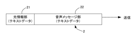
PLC31は、内部メモリ311に書き込まれた情報から、状態報知装置1に適合した形式の送信データ2を生成する。送信データ2は、例えば、図4に示すように、光情報部(第1イベント情報)21と、音声メッセージ部(第2イベント情報)22とを有するテキストデータで構成されている。光情報部21は、例えば、「光、赤点灯」、「光、黄色点灯、」、「光、黄色点滅1」、「光、黄色点滅2」といったテキストデータで構成され、光の色と点灯パターンが含まれている。点灯パターンとは、例えば、点灯、点滅1、点滅2等の文字で規定することができ、これらは、常時点灯した状態、異なる2つのパターンの点滅した状態を示している。
The PLC 31 generates transmission data 2 in a format suitable for the status notification device 1 from the information written in the internal memory 311 . The transmission data 2 is composed of text data having an optical information section (first event information) 21 and a voice message section (second event information) 22, for example, as shown in FIG. The light information section 21 is composed of text data such as "light, red lighting", "light, yellow lighting", "light, blinking yellow 1", and "light, blinking yellow 2". contains a pattern. The lighting pattern can be specified by characters such as lighting, flashing 1, flashing 2, etc. These indicate a constantly lit state and two different blinking patterns.
音声メッセージ部22は、上記内部メモリ311に記載されたテキストデータを抽出したものであり、例えば、「音、停止しました。」といったテキストデータで構成されている。これら光情報部21と音声メッセージ部22とをテキストデータとして含む送信データ2が、内部メモリ311が書き換えられるたびに生成され、通信インタフェース32により状態報知装置1に送信される。
The voice message section 22 is obtained by extracting the text data described in the internal memory 311, and is composed of text data such as "Sound has stopped." The transmission data 2 including the optical information section 21 and the voice message section 22 as text data is generated each time the internal memory 311 is rewritten and transmitted to the status notification device 1 via the communication interface 32 .
送信データ2の形式は、上述したものに限定されず、状態報知装置1に合わせて種々の形態が可能である。例えば、図5に示すように、光情報部21をテキストデータではなく、光の色、点灯状態を示すコマンドにすることができる。コマンドは、種々の形態で記載することができ、例えば、状態報知装置1で読み取り可能に規定された番号、文字、記号等で表すことができる。このコマンドとともに生成される音声メッセージ部22は、上述したとおりである。この場合、光情報部21と音声メッセージ部22の形式が異なるため、通信インタフェース32は、送信データ2を2回に分けて送信する。例えば、一回目に光情報部21のコマンドを送信し、二回目に音声メッセージ部22のテキストデータを送信することができる。なお、これらの送信の順序を反対にすることもできる。
The format of the transmission data 2 is not limited to the one described above, and various formats are possible according to the state notification device 1. For example, as shown in FIG. 5, the light information section 21 can be a command indicating the color of light and the lighting state instead of text data. Commands can be described in various forms, and can be represented, for example, by numbers, letters, symbols, etc. that are readable by the status notification device 1 . The voice message portion 22 generated with this command is as described above. In this case, since the formats of the optical information section 21 and the voice message section 22 are different, the communication interface 32 divides the transmission data 2 into two and transmits them. For example, the command of the optical information section 21 can be transmitted the first time, and the text data of the voice message section 22 can be transmitted the second time. Note that the order of these transmissions can be reversed.
通信インタフェース32は、例えば、有線LAN(Local Area Network)モジュール、無線LANモジュール等であり、有線又は無線通信を行うためのインタフェースである。すなわち、通信インタフェース32は、所定の通信プロトコルにしたがって、有線または無線のネットワーク7を介して送信データ2を状態報知装置1へ送信する構成である。
The communication interface 32 is, for example, a wired LAN (Local Area Network) module, a wireless LAN module, or the like, and is an interface for performing wired or wireless communication. That is, the communication interface 32 is configured to transmit the transmission data 2 to the status notification device 1 via the wired or wireless network 7 according to a predetermined communication protocol.
<1-2.状態報知装置>
次に、本実施形態に係る状態報知装置1のハードウェア構成の一例について説明する。図6は状態報知装置の正面図、図7は状態報知装置の背面図、図8は状態報知装置のハードウェア構成の一例である。 <1-2. Status notification device>
Next, an example of the hardware configuration of thestate notification device 1 according to this embodiment will be described. 6 is a front view of the state notification device, FIG. 7 is a rear view of the state notification device, and FIG. 8 is an example of the hardware configuration of the state notification device.
次に、本実施形態に係る状態報知装置1のハードウェア構成の一例について説明する。図6は状態報知装置の正面図、図7は状態報知装置の背面図、図8は状態報知装置のハードウェア構成の一例である。 <1-2. Status notification device>
Next, an example of the hardware configuration of the
図5~図7に示すように、この状態報知装置1は、基台11と、この基台11の上部から延びるLEDユニット(発光ユニット)12と、ボディ13と、を有しており、基台11の外面には、スピーカ(音声ユニット)112、各種操作ボタン113が設けられている。また、基台11の内部には、制御部114、記憶部115、通信インタフェース116、及び外部インタフェース117、が内蔵されている。なお、図8では、通信インターフェース116を「通信I/F」と、外部インタフェース117を「外部I/F」と記載している。
As shown in FIGS. 5 to 7, the state notification device 1 has a base 11, an LED unit (light emitting unit) 12 extending from the top of the base 11, and a body 13. A speaker (audio unit) 112 and various operation buttons 113 are provided on the outer surface of the base 11 . Further, inside the base 11, a control unit 114, a storage unit 115, a communication interface 116, and an external interface 117 are built. 8, the communication interface 116 is described as "communication I/F", and the external interface 117 is described as "external I/F".
基台11は平面視矩形状に形成されており、制御部114等を収容する筐体として機能する。LEDユニット12は、円柱状に形成されており、上部に3つの発光部、つまり上から下に並ぶ第1、第2,及び第3発光部121~123が設けられている。各発光部121~123は、円柱状に形成されており、それぞれ、赤、黄、緑の発光を行うようにLEDが内蔵されている。これら発光部121~123が、上述した生産設備3の状態に応じて発光する。
The base 11 is formed in a rectangular shape in plan view, and functions as a housing that houses the control unit 114 and the like. The LED unit 12 is formed in a cylindrical shape, and is provided with three light-emitting portions in the upper portion, that is, first, second, and third light-emitting portions 121 to 123 arranged from top to bottom. Each of the light emitting portions 121 to 123 is formed in a columnar shape, and LEDs are built therein so as to emit red, yellow, and green light, respectively. These light emitting units 121 to 123 emit light according to the state of the production equipment 3 described above.
図6に示すように、基台11の前面の下部には上述したスピーカ112が設けられ、後述するように、このスピーカ112から生産設備3の状態が表す音声で出力される。図示を省略するが、音声のボリュームを調整するボリュームスイッチも設けられている。また、基台11の前面において、スピーカ112の上方には、各種操作ボタン113が設けられている。操作ボタン113には、例えば、操作をリセットするリセットスイッチ(非図示)、音声の再生スイッチ118等が含まれている。
As shown in FIG. 6, the above-described speaker 112 is provided at the bottom of the front surface of the base 11, and as will be described later, the speaker 112 outputs sounds representing the state of the production equipment 3. Although illustration is omitted, a volume switch for adjusting the volume of sound is also provided. Various operation buttons 113 are provided above the speaker 112 on the front surface of the base 11 . The operation buttons 113 include, for example, a reset switch (not shown) for resetting operations, an audio reproduction switch 118, and the like.
再生スイッチ118は、音声を再生するためのスイッチであるが、本実施形態においては、音声の再生について2種類の設定を行うことができる。第1設定では、再生スイッチ118を押すことなく、生産設備3の状態をスピーカ112から出力する設定である。一方、第2設定では、再生スイッチ118を押したときのみ、生産設備3の状態をスピーカ112から出力する設定である。これらの設定の用途については後述する。その他、操作ボタン113には、必要に応じて種々の機能を有するボタン、スイッチなどを設けることができる。
The playback switch 118 is a switch for playing back audio. In this embodiment, two types of settings can be made for playback of audio. In the first setting, the state of the production equipment 3 is output from the speaker 112 without pressing the reproduction switch 118 . On the other hand, in the second setting, the state of the production facility 3 is output from the speaker 112 only when the playback switch 118 is pressed. The use of these settings will be described later. In addition, the operation button 113 can be provided with buttons, switches, etc. having various functions as required.
図7に示すように、基台11の背面には、上述した通信インタフェース116及び外部インタフェース117用のコネクタが設けられている。
As shown in FIG. 7, connectors for the above-described communication interface 116 and external interface 117 are provided on the rear surface of the base 11 .
次に、制御部114について説明する。図8に示すように、制御部114は、CPU、RAM、ROM等を含み、プログラム及びデータに基づいて各種情報処理を実行するように構成される。記憶部115は、例えば、HDD、SDD等の補助記憶装置で構成され、状態報知プログラム151、送信データ2、音声データ4、状態報知装置1を駆動するための種々のデータ5を記憶する。状態報知プログラム151は、状態報知装置1に生産設備3の状態を報知させるためのプログラムである。制御部114は、この状態報知プログラム151を解釈及び実行することで、後述する各ステップの処理を実行するように構成される。
Next, the control unit 114 will be explained. As shown in FIG. 8, the control unit 114 includes a CPU, RAM, ROM, etc., and is configured to execute various types of information processing based on programs and data. The storage unit 115 is composed of, for example, an auxiliary storage device such as an HDD or an SDD, and stores a state notification program 151 , transmission data 2 , voice data 4 , and various data 5 for driving the state notification device 1 . The status reporting program 151 is a program for causing the status reporting device 1 to report the status of the production facility 3 . The control unit 114 is configured to interpret and execute the status notification program 151 to execute the processing of each step described later.
外部インタフェース117は、外部装置と接続するためのインタフェースであり、接続する外部装置に応じて適宜構成される。例えば、外部インタフェース117には、キーボード等の入力装置及びディスプレイ等の出力装置等を適宜接続することができる。
The external interface 117 is an interface for connecting with an external device, and is appropriately configured according to the external device to be connected. For example, an input device such as a keyboard and an output device such as a display can be appropriately connected to the external interface 117 .
通信インタフェース116は、生産設備3に設けられているものと同様であるため、説明を省略する。
The communication interface 116 is the same as that provided in the production equipment 3, so the description is omitted.
なお、状態報知装置1の具体的なハードウェア構成に関して、実施形態に応じて、適宜、構成要素の省略、置換及び追加が可能である。例えば、制御部114は、複数のプロセッサを含んでもよい。また、制御部114は、FPGAにより構成されてもよい。記憶部115は、制御部114に含まれるRAM及びROMにより構成されてもよい。
Regarding the specific hardware configuration of the status notification device 1, it is possible to omit, replace, and add components as appropriate according to the embodiment. For example, controller 114 may include multiple processors. Also, the control unit 114 may be configured by an FPGA. The storage unit 115 may be configured by RAM and ROM included in the control unit 114 .
<2.状態報知装置のソフトウエア構成>
次に、状態報知装置1のソフトウエア構成について説明する。図9は、状態報知装置のソフトウエア構成を示すブロック図である。図9に示すように、状態報知装置1の制御部114は、記憶部115に記憶された状態報知プログラム151をRAMに展開すると、その状態報知プログラム151をCPUにより解釈及び実行して、受信部(受付部)61、データ判別部(受付部)62、発光制御部63、音声データ生成部64、及び音声制御部65を備えたコンピュータとして機能する。 <2. Software configuration of status notification device>
Next, the software configuration of thestate notification device 1 will be described. FIG. 9 is a block diagram showing the software configuration of the status notification device. As shown in FIG. 9, when the state notification program 151 stored in the storage unit 115 is developed in the RAM, the control unit 114 of the state notification device 1 causes the CPU to interpret and execute the state notification program 151, and the receiving unit It functions as a computer including a (reception unit) 61 , a data determination unit (reception unit) 62 , a light emission control unit 63 , an audio data generation unit 64 and an audio control unit 65 .
次に、状態報知装置1のソフトウエア構成について説明する。図9は、状態報知装置のソフトウエア構成を示すブロック図である。図9に示すように、状態報知装置1の制御部114は、記憶部115に記憶された状態報知プログラム151をRAMに展開すると、その状態報知プログラム151をCPUにより解釈及び実行して、受信部(受付部)61、データ判別部(受付部)62、発光制御部63、音声データ生成部64、及び音声制御部65を備えたコンピュータとして機能する。 <2. Software configuration of status notification device>
Next, the software configuration of the
受信部(受付部)61は、生産設備3から送信された送信データ2を受信する。受信された送信データ2は、記憶部115またはRAMに記憶される。
A receiving unit (receiving unit) 61 receives the transmission data 2 transmitted from the production equipment 3 . The received transmission data 2 is stored in storage unit 115 or RAM.
データ判別部(受付部)62は、受信部(受付部)61が受信した送信データ2から光情報部21及び音声メッセージ部22を抽出し、後述する発光制御部63及び音声データ生成部64に送信する。例えば、送信データ2の形式がテキストデータである場合には、発光制御部63に送信するデータとして、「光、赤点灯」等のテキストデータを抽出するとともに、音声データ生成部64に送信するデータとして、「音、停止しました。」等のテキストデータを抽出する。なお、受信部(受付部)61及びデータ判別部(受付部)62が、本発明の受付部を構成する。
A data discriminating unit (receiving unit) 62 extracts the optical information unit 21 and the voice message unit 22 from the transmission data 2 received by the receiving unit (receiving unit) 61, and outputs them to the light emission control unit 63 and the voice data generation unit 64, which will be described later. Send. For example, when the format of the transmission data 2 is text data, text data such as "light, red lighting" is extracted as data to be transmitted to the light emission control unit 63, and data to be transmitted to the voice data generation unit 64 is extracted. , extract text data such as "Sound has stopped." The receiving section (receiving section) 61 and the data determining section (receiving section) 62 constitute the receiving section of the present invention.
一方、送信データ2が、別々に送信された2つのデータで構成される場合には、受信した光情報部21のコマンドを発光制御部63に送信するとともに、音声メッセージ部22のテキストデータを音声データ生成部64に送信する。
On the other hand, when the transmission data 2 consists of two pieces of data transmitted separately, the received command of the optical information section 21 is transmitted to the light emission control section 63, and the text data of the voice message section 22 is transmitted as a voice. It is transmitted to the data generator 64 .
発光制御部63は、データ判別部(受付部)62から受信した光情報部21のデータに基づいて、LEDユニット12の発光を制御する機能を有している。例えば、「光、赤点灯」等のテキストデータを受信すると、これをコマンドに変換し、このコマンドによってLEDユニット12の第1発光部121を点灯させる。また、データ判別部(受付部)62からコマンドが送信された場合には、そのコマンドによってLEDユニット12の発光を制御する。その他、発光制御部63は、光の強度、色の調整、発光時間などの制御を行うこともできる。
The light emission control section 63 has a function of controlling light emission of the LED unit 12 based on the data of the light information section 21 received from the data determination section (accepting section) 62 . For example, when text data such as "light, red light" is received, it is converted into a command, and the command causes the first light emitting section 121 of the LED unit 12 to light up. Further, when a command is transmitted from the data discrimination section (accepting section) 62, the light emission of the LED unit 12 is controlled according to the command. In addition, the light emission control unit 63 can also control light intensity, color adjustment, light emission time, and the like.
音声データ生成部64は、データ判別部(受付部)62から受信した音声メッセージ部22のテキストデータからMP3、WAV等の形式の音声データを生成する。例えば、公知のText-to-Speech(TTS)技術により、テキストデータを読み上げた音声データを生成する。生成された音声データは、音声制御部65に送信される。また、生成された音声データは、記憶部115に記憶される。
The voice data generation unit 64 generates voice data in formats such as MP3 and WAV from the text data of the voice message unit 22 received from the data determination unit (reception unit) 62 . For example, the well-known Text-to-Speech (TTS) technology is used to generate voice data by reading the text data. The generated audio data is transmitted to the audio control section 65 . Also, the generated audio data is stored in the storage unit 115 .
音声制御部65は、音声データ生成部64から送信された音声データに基づき、テキストデータの読み上げ音を出力するように、スピーカ112を制御する。その他、音声制御部65は、音声の大きさ、音程、音色、及び再生速度を制御することもできる。また、音声制御部65は、上記機能に加え、再生スイッチ118が押下されたときの再生指令受付部としても機能し、再生スイッチ118が押下されたときに生成される再生指令により、音声の再生を行うようになっている。
The voice control unit 65 controls the speaker 112 so as to output the text data reading sound based on the voice data transmitted from the voice data generation unit 64 . In addition, the audio control unit 65 can also control the volume, pitch, timbre, and playback speed of audio. In addition to the functions described above, the audio control unit 65 also functions as a reproduction command reception unit when the reproduction switch 118 is pressed, and reproduces audio according to the reproduction command generated when the reproduction switch 118 is pressed. is to be performed.
<3.状態報知装置による生産設備の状態の報知方法>
次に、上記のように構成された状態報知装置による生産設備の状態の報知方法について、図10及び図11のフローチャートを参照しつつ説明する。 <3. Method of notifying the state of production equipment by the state notifying device>
Next, a method of notifying the state of the production equipment by the state notifying device configured as described above will be described with reference to the flow charts of FIGS. 10 and 11. FIG.
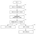
まず、上述した再生スイッチ118が第1設定になっている場合について図10のフローチャートを参照しつつ説明する。図10に示すように、生産設備3の内部メモリ311に生産設備3の状態が書き込まれると(ステップS11)、PLC31は、上記のように内部メモリ311から送信データ2を生成する(ステップS12)。生成された送信データ2は、状態報知装置1の受信部(受付部)61に送信される(ステップS13)。
First, the case where the playback switch 118 is set to the first setting will be described with reference to the flowchart of FIG. As shown in FIG. 10, when the state of the production equipment 3 is written in the internal memory 311 of the production equipment 3 (step S11), the PLC 31 generates transmission data 2 from the internal memory 311 as described above (step S12). . The generated transmission data 2 is transmitted to the receiving section (accepting section) 61 of the status notification device 1 (step S13).
受信部61(受付部)で受信された送信データ2は、データ判別部(受付部)62に送信され、データ判別部(受付部)62により、光情報部21のテキストデータまたはコマンドが抽出されるとともに、音声メッセージ部22のテキストデータが抽出される(ステップS14)。
The transmission data 2 received by the receiving unit 61 (receiving unit) is transmitted to the data discriminating unit (receiving unit) 62, and the data discriminating unit (receiving unit) 62 extracts the text data or command of the optical information unit 21. At the same time, the text data of the voice message section 22 is extracted (step S14).
抽出された光情報部21のテキストデータまたはコマンドは、発光制御部63に送信され、LEDユニット12の発光が行われる(ステップS15)。これと並行して、抽出された音声メッセージ部22のテキストデータは、音声データ生成部64に送信され、音声データが生成される(ステップS16)。また、この音声データは記憶部115に記憶される。この音声データに基づいて、音声制御部65は、スピーカ112からテキストデータの読み上げ音を出力させる(ステップS17)。
The extracted text data or command of the light information section 21 is transmitted to the light emission control section 63, and the LED unit 12 emits light (step S15). In parallel with this, the extracted text data of the voice message section 22 is transmitted to the voice data generation section 64, and voice data is generated (step S16). Also, this voice data is stored in the storage unit 115 . Based on this voice data, the voice control unit 65 causes the speaker 112 to output the reading sound of the text data (step S17).
次に、上述した再生スイッチ118が第2設定になっている場合について図11のフローチャートを参照しつつ説明する。図11に示すステップS21からステップS26は、図9のステップS11からステップS16と同じであるので説明を省略する。ステップS26音声データが生成された後、再生スイッチ118が押下された場合には(ステップS27のYES)、再生指令が音声制御部65に送信され、音声制御部65により、スピーカ112からテキストデータの読み上げ音が出力される(ステップS28)。したがって、再生スイッチ118が押下されるまでは、読み上げ音は出力されない(ステップS27のNO)。また、再生スイッチ118が押下されると、音声制御部65は、記憶部115に読み上げ音が再生されたことを記憶する(ステップS29)。これにより、読み上げ音が再生されたことを事後的に確認することができる。なお、ステップS28とS29の順序は反対でもよい。
Next, the case where the playback switch 118 is set to the second setting will be described with reference to the flowchart of FIG. Steps S21 to S26 shown in FIG. 11 are the same as steps S11 to S16 in FIG. 9, so description thereof will be omitted. After the voice data is generated in step S26, if the playback switch 118 is pressed (YES in step S27), a playback command is sent to the voice control unit 65, and the voice control unit 65 outputs the text data from the speaker 112. A reading sound is output (step S28). Therefore, the reading sound is not output until the playback switch 118 is pressed (NO in step S27). Further, when the reproduction switch 118 is pressed, the voice control unit 65 stores the fact that the reading sound is reproduced in the storage unit 115 (step S29). Thereby, it is possible to confirm after the fact that the reading sound has been reproduced. Note that the order of steps S28 and S29 may be reversed.
こうして、生産設備3の内部メモリ311に状態が書き込まれる度に、その状態がLEDユニット12により光で報知されるとともに、スピーカ112からの出力により音声で報知される。
In this way, each time a state is written to the internal memory 311 of the production equipment 3, the state is notified by light from the LED unit 12 and by sound from the output from the speaker 112.
<4.特徴>
以上のように、本実施形態によれば、次の効果を得ることができる。
(1)生産設備3の状態を光と音の両方で報知することができるため、ユーザが視覚と聴覚の両方で生産設備3の状態を確認することができる。 <4. Features>
As described above, according to this embodiment, the following effects can be obtained.
(1) Since the state of theproduction facility 3 can be notified both by light and sound, the user can confirm the state of the production facility 3 both visually and audibly.
以上のように、本実施形態によれば、次の効果を得ることができる。
(1)生産設備3の状態を光と音の両方で報知することができるため、ユーザが視覚と聴覚の両方で生産設備3の状態を確認することができる。 <4. Features>
As described above, according to this embodiment, the following effects can be obtained.
(1) Since the state of the
(2)生産設備3では、音声データ用のテキストデータを予め準備しておけばよいため、音声データを生成するのに比べ、データの生成が簡単であり、生成時間を大幅に短縮することができる。したがって、状態報知装置1の導入までの時間を短縮することができる。また、音声データの代わりにテキストデータを生成して記憶しておくため、データ量を小さくすることができ、多種多様な音声に対応したテキストデータを簡単に生成することができる。さらに、ネットワーク7においては、容量の小さいテキストデータを送信すればよいため、データの送信時間を短縮することができ、ひいては状態の報知までの時間を短縮することができる。
(2) In the production equipment 3, since text data for voice data should be prepared in advance, data generation is simpler than voice data generation, and generation time can be greatly shortened. can. Therefore, the time until the state notification device 1 is introduced can be shortened. Also, since text data is generated and stored instead of voice data, the amount of data can be reduced, and text data corresponding to a wide variety of voices can be easily generated. Furthermore, since text data with a small capacity can be transmitted over the network 7, the data transmission time can be shortened, and the time until the status notification can be shortened.
(3)再生スイッチ118を第2設定としておくことで、関係のないユーザに聞かれると不都合な音声メッセージの出力を停止することができる。また、生産設備3の状態の変化時に、状態報知装置1の周囲にユーザがいなかった場合、事後的に再生スイッチ118を押下することで、状態の内容を聞くことができる。さらに、再生スイッチ118を押下することで、音声が再生されたことが記憶されるため、報知を認識したことを確認することができる。
(3) By setting the playback switch 118 to the second setting, it is possible to stop outputting an inconvenient voice message when heard by an unrelated user. Also, when the state of the production equipment 3 changes, if the user is not around the state notification device 1, the content of the state can be heard by pressing the reproduction switch 118 afterwards. Further, by pressing the reproduction switch 118, the fact that the voice has been reproduced is memorized, so that it is possible to confirm that the notification has been recognized.
<5.変形例>
以上、本発明の第1実施形態について説明したが、本発明は上記第1実施形態に限定されるものではなく、その趣旨を逸脱しない限りにおいて、種々の変更が可能である。なお、以下に説明する変形例は適宜組み合わせ可能である。また、以下の変形例は、後述する第2実施形態においても適宜適用することができる。 <5. Variation>
Although the first embodiment of the present invention has been described above, the present invention is not limited to the above-described first embodiment, and various modifications are possible without departing from the gist thereof. It should be noted that the modified examples described below can be appropriately combined. Moreover, the following modifications can also be appropriately applied to the second embodiment described later.
<5-1>
上記実施形態では、送信データ2の光情報部21のテキストまたはコマンドにより、LEDユニット12を発光させているが、例えば、音声メッセージ部22のテキストデータの内容によって発光の方法を変更するようにしてもよい。例えば、音声メッセージ部22のテキストデータの内容が「温度異常です」等の急ぎの対応を要する場合には、発光制御部63により、視認の程度を強めるため、発光の強度を強くしたり、点滅の周期を変化させる(例えば、短くする)ことができる。 <5-1>
In the above embodiment, theLED unit 12 is caused to emit light according to the text or command in the light information section 21 of the transmission data 2. However, for example, the light emission method may be changed according to the content of the text data in the voice message section 22. good too. For example, if the contents of the text data in the voice message section 22 require an urgent response such as "The temperature is abnormal", the light emission control section 63 increases the intensity of the light emission or flashes the light to enhance the degree of visibility. can be changed (eg, shortened).
上記実施形態では、送信データ2の光情報部21のテキストまたはコマンドにより、LEDユニット12を発光させているが、例えば、音声メッセージ部22のテキストデータの内容によって発光の方法を変更するようにしてもよい。例えば、音声メッセージ部22のテキストデータの内容が「温度異常です」等の急ぎの対応を要する場合には、発光制御部63により、視認の程度を強めるため、発光の強度を強くしたり、点滅の周期を変化させる(例えば、短くする)ことができる。 <5-1>
In the above embodiment, the
<5-2>
上記実施形態では、送信データ2の音声メッセージ部22に基づいて、スピーカ112から読み上げ音を出力しているが、音声メッセージ部22のテキストデータの内容によって読み上げ音が変化するように音声データを生成することができる。例えば、音声メッセージ部22のテキストデータの内容が「異常温度です」等の急ぎの対応を要する場合には、音声制御部65により、聞き取りの程度を強めるため、再生される音声の大きさ、音程、音色、及び再生速度の少なくとも1つを変化させることができる。例えば、再生される音声の大きさを大きくしたり、音程を高めることで、音声に注目させるようにすることができる。 <5-2>
In the above embodiment, the reading sound is output from thespeaker 112 based on the voice message portion 22 of the transmission data 2, but the voice data is generated so that the reading sound changes depending on the content of the text data of the voice message portion 22. can do. For example, when the contents of the text data in the voice message section 22 require an urgent response such as "abnormal temperature", the voice control section 65 adjusts the volume and pitch of the reproduced voice in order to enhance the degree of comprehension. , timbre, and playback speed. For example, by increasing the volume of the reproduced sound or raising the pitch, it is possible to draw attention to the sound.
上記実施形態では、送信データ2の音声メッセージ部22に基づいて、スピーカ112から読み上げ音を出力しているが、音声メッセージ部22のテキストデータの内容によって読み上げ音が変化するように音声データを生成することができる。例えば、音声メッセージ部22のテキストデータの内容が「異常温度です」等の急ぎの対応を要する場合には、音声制御部65により、聞き取りの程度を強めるため、再生される音声の大きさ、音程、音色、及び再生速度の少なくとも1つを変化させることができる。例えば、再生される音声の大きさを大きくしたり、音程を高めることで、音声に注目させるようにすることができる。 <5-2>
In the above embodiment, the reading sound is output from the
なお、このような音声の変化は、音声データ生成部64によって行うこともできる。すなわち、音声メッセージ部22のテキストデータの内容に応じて、再生される音声の大きさ、音程、音色、及び再生速度の少なくとも1つを変化させた音声データを生成することができる。
It should be noted that such a voice change can also be performed by the voice data generation unit 64. That is, it is possible to generate voice data in which at least one of the volume, pitch, timbre, and playback speed of the voice to be played is changed according to the contents of the text data of the voice message section 22 .
<5-3>
上記実施形態では、送信データ2に含まれるテキストデータに基づいて、音声データが生成されているが、音声データの基礎となるテキストデータには種々の情報を付加することできる。例えば、状態が変化した生産設備3を特定する情報(生産設備3の番号やIPアドレス等)、状態の変化が発生した時刻をテキストデータに付加することができる。これにより、音声データ生成部64では、状態に加え、状態が変化した生産設備3及び時刻を読み上げ音に加えた音声データを生成することができる。 <5-3>
In the above embodiment, the voice data is generated based on the text data included in thetransmission data 2, but various information can be added to the text data that forms the basis of the voice data. For example, information specifying the production facility 3 whose status has changed (the number or IP address of the production facility 3, etc.) and the time at which the status change occurred can be added to the text data. As a result, the voice data generation unit 64 can generate voice data in which the state, the production equipment 3 whose state has changed, and the time are added to the reading sound.
上記実施形態では、送信データ2に含まれるテキストデータに基づいて、音声データが生成されているが、音声データの基礎となるテキストデータには種々の情報を付加することできる。例えば、状態が変化した生産設備3を特定する情報(生産設備3の番号やIPアドレス等)、状態の変化が発生した時刻をテキストデータに付加することができる。これにより、音声データ生成部64では、状態に加え、状態が変化した生産設備3及び時刻を読み上げ音に加えた音声データを生成することができる。 <5-3>
In the above embodiment, the voice data is generated based on the text data included in the
<5-4>
再生スイッチ118が所定時間押下されない場合には、状態報知装置1から所定のユーザにメール、電話等で状態の変化を通知することができる。これにより、ユーザが生産設備3の状態の変化を確実に認識することができる。 <5-4>
If theplayback switch 118 is not pressed for a predetermined time, the state notification device 1 can notify a predetermined user of the change in state by e-mail, telephone, or the like. This allows the user to reliably recognize changes in the state of the production equipment 3 .
再生スイッチ118が所定時間押下されない場合には、状態報知装置1から所定のユーザにメール、電話等で状態の変化を通知することができる。これにより、ユーザが生産設備3の状態の変化を確実に認識することができる。 <5-4>
If the
<5-5>
本発明の発光ユニットは、LEDユニット12以外でもよく、複数種の光を発光できるものであれば、電球等の光源でもよい。例えば、単色の光であっても、点滅灯の複数のパターンの発光ができればよい。また、本発明の音声ユニットとして使用されるスピーカ112の種類は特には限定されず、読み上げ音が出力されればよい。 <5-5>
The light-emitting unit of the present invention may be other than theLED unit 12, and may be a light source such as a light bulb as long as it can emit multiple types of light. For example, even if it is a monochromatic light, it is sufficient if it can emit a plurality of patterns of blinking lights. Also, the type of the speaker 112 used as the audio unit of the present invention is not particularly limited as long as it outputs reading sound.
本発明の発光ユニットは、LEDユニット12以外でもよく、複数種の光を発光できるものであれば、電球等の光源でもよい。例えば、単色の光であっても、点滅灯の複数のパターンの発光ができればよい。また、本発明の音声ユニットとして使用されるスピーカ112の種類は特には限定されず、読み上げ音が出力されればよい。 <5-5>
The light-emitting unit of the present invention may be other than the
<5-6>
上記実施形態では、音声データ生成部64を制御部114により構成しているが、例えば、公知のTTS技術により音声データを生成するソフトウエアモジュールを別途設けてもよい。 <5-6>
In the above embodiment, the voicedata generation unit 64 is configured by the control unit 114. However, for example, a software module that generates voice data using a known TTS technique may be separately provided.
上記実施形態では、音声データ生成部64を制御部114により構成しているが、例えば、公知のTTS技術により音声データを生成するソフトウエアモジュールを別途設けてもよい。 <5-6>
In the above embodiment, the voice
<5-7>
記憶部115には、音声データが記憶されるが、例えば、受信部(受付部)61が、過去に受信した音声用のテキストデータと同じテキストデータを受信したときには、記憶部115に記憶されている、そのテキストデータに対応する音声データを読み出し、これによって読み上げ音を再生することができる。これにより、音声データの生成時間を短縮することができる。 <5-7>
Thestorage unit 115 stores voice data. It is possible to read the voice data corresponding to the text data, and thereby reproduce the read-aloud sound. As a result, the time required to generate audio data can be shortened.
記憶部115には、音声データが記憶されるが、例えば、受信部(受付部)61が、過去に受信した音声用のテキストデータと同じテキストデータを受信したときには、記憶部115に記憶されている、そのテキストデータに対応する音声データを読み出し、これによって読み上げ音を再生することができる。これにより、音声データの生成時間を短縮することができる。 <5-7>
The
<5-8>
状態報知装置1は、提供されるサービス専用に設計された情報処理装置、汎用のデスクトップPC、タブレットPC等であってもよい。したがって、図6及び図7で示した状態報知装置の形態は一例であり、適宜変更することができる。また、上記実施形態では、LEDユニット12及びスピーカ112を有する状態報知装置1を用いているが、例えば、上記制御部114を有するPLC等のコンピュータ(本発明の状態報知ユニット)を準備し、これにLEDユニットやスピーカ、あるいは記憶装置を外部接続したものを状態報知装置として使用することもできる。また、上記制御部114を有するコンピュータを状態報知ユニットとして、監視対象装置に内蔵することもできる。 <5-8>
Thestatus notification device 1 may be an information processing device designed exclusively for the service provided, a general-purpose desktop PC, a tablet PC, or the like. Therefore, the form of the state notification device shown in FIGS. 6 and 7 is an example, and can be changed as appropriate. Further, in the above-described embodiment, the state notification device 1 having the LED unit 12 and the speaker 112 is used. An LED unit, a speaker, or a device to which a storage device is externally connected can also be used as the status notification device. Also, a computer having the control unit 114 can be incorporated in the monitoring target device as a status reporting unit.
状態報知装置1は、提供されるサービス専用に設計された情報処理装置、汎用のデスクトップPC、タブレットPC等であってもよい。したがって、図6及び図7で示した状態報知装置の形態は一例であり、適宜変更することができる。また、上記実施形態では、LEDユニット12及びスピーカ112を有する状態報知装置1を用いているが、例えば、上記制御部114を有するPLC等のコンピュータ(本発明の状態報知ユニット)を準備し、これにLEDユニットやスピーカ、あるいは記憶装置を外部接続したものを状態報知装置として使用することもできる。また、上記制御部114を有するコンピュータを状態報知ユニットとして、監視対象装置に内蔵することもできる。 <5-8>
The
<5-9>
上記実施形態では、生産設備3の状態を報知することを例にしたが、本発明の状態報知装置1の対象となる監視対象装置は、生産設備3以外でもよく、例えば、プリンタ、サーバー、ネットワークカメラ、防災システム、防犯システム、入退室システム、環境監視システム、受発注システム等の状態が変化する各種の装置とすることができる。また、本発明の監視対象装置は、上述した生産設備3のような構成に限定されるものではなく、少なくとも状態の変化が記憶され、これに基づいて送信データを生成できるものであればよい。 <5-9>
In the above-described embodiment, the status of theproduction facility 3 is reported as an example, but the monitoring target device to be monitored by the status reporting device 1 of the present invention may be other than the production facility 3, such as a printer, a server, and a network. It can be a camera, a disaster prevention system, a crime prevention system, an entrance/exit system, an environment monitoring system, an order receiving/ordering system, and various other devices whose states change. Also, the monitoring target device of the present invention is not limited to the configuration of the production facility 3 described above, and may be any device that can store at least changes in state and generate transmission data based on this.
上記実施形態では、生産設備3の状態を報知することを例にしたが、本発明の状態報知装置1の対象となる監視対象装置は、生産設備3以外でもよく、例えば、プリンタ、サーバー、ネットワークカメラ、防災システム、防犯システム、入退室システム、環境監視システム、受発注システム等の状態が変化する各種の装置とすることができる。また、本発明の監視対象装置は、上述した生産設備3のような構成に限定されるものではなく、少なくとも状態の変化が記憶され、これに基づいて送信データを生成できるものであればよい。 <5-9>
In the above-described embodiment, the status of the
<B.第2実施形態>
以下、本発明に係る状態報知装置の第2実施形態について、図面を参照しつつ説明する。第2実施形態が第1実施形態と相違するのは、(1)生産設備が送信データを生成しないこと、及び(2)状態報知装置のソフトウエア構成である。したがって、以下では、主として、第1実施形態と相違する点について説明し、同様の構成については説明を省略する。 <B. Second Embodiment>
A second embodiment of a state notification device according to the present invention will be described below with reference to the drawings. The second embodiment differs from the first embodiment in (1) that the production facility does not generate transmission data and (2) the software configuration of the status notification device. Therefore, in the following, mainly the points that are different from the first embodiment will be described, and descriptions of the similar configurations will be omitted.
<1.生産設備>
上記のように、生産設備では、送信データを生成しないが、PLCの内部メモリに、状態の変化が書き込まれる点は同じである。 <1. Production equipment>
As described above, the production facility does not generate transmission data, but it is the same in that state changes are written to the internal memory of the PLC.
上記のように、生産設備では、送信データを生成しないが、PLCの内部メモリに、状態の変化が書き込まれる点は同じである。 <1. Production equipment>
As described above, the production facility does not generate transmission data, but it is the same in that state changes are written to the internal memory of the PLC.
<2.状態報知装置>
本実施形態に係る生産設備3では送信データを送信しないため、状態報知装置1のソフトウエア構成が相違している。以下、図12に示すブロック図を参照しつつ説明する。 <2. Status notification device>
Since theproduction equipment 3 according to this embodiment does not transmit transmission data, the software configuration of the status notification device 1 is different. Description will be made below with reference to the block diagram shown in FIG.
本実施形態に係る生産設備3では送信データを送信しないため、状態報知装置1のソフトウエア構成が相違している。以下、図12に示すブロック図を参照しつつ説明する。 <2. Status notification device>
Since the
図12に示すように、状態報知装置1の制御部114は、記憶部115に記憶された状態報知プログラム151をRAMに展開すると、その状態報知プログラム151をCPUにより解釈及び実行して、発光制御部63、音声データ生成部64、音声制御部65、及びイベント情報生成部66を備えたコンピュータとして機能する。イベント情報生成部66以外の構成は、第1実施形態と同じであるため、説明を省略する。
As shown in FIG. 12, when the control unit 114 of the state notification device 1 develops the state notification program 151 stored in the storage unit 115 in the RAM, the CPU interprets and executes the state notification program 151 to control light emission. It functions as a computer including a section 63 , an audio data generation section 64 , an audio control section 65 and an event information generation section 66 . Configurations other than the event information generation unit 66 are the same as those in the first embodiment, and thus description thereof is omitted.
イベント情報生成部66は、所定時間おきに生産設備3のPLC31の内部メモリ311を読み出し、状態の変化を監視する。イベント情報生成部66が内部メモリ311の書き換えを検知したときには、内部メモリ311の内容に基づき、送信データ8を生成する。送信データ8は、第1送信データ(第1イベント情報)81及び第2送信データ(第2イベント情報)82を含む。各送信データ81,82は、記憶部115に記憶されている報知データ9を参照して生成される。
The event information generation unit 66 reads out the internal memory 311 of the PLC 31 of the production equipment 3 at predetermined time intervals and monitors changes in the state. When the event information generator 66 detects that the internal memory 311 has been rewritten, it generates the transmission data 8 based on the contents of the internal memory 311 . The transmission data 8 includes first transmission data (first event information) 81 and second transmission data (second event information) 82 . Each of the transmission data 81 and 82 is generated with reference to the notification data 9 stored in the storage section 115 .
報知データ9は、検知された各状態(図3参照)と対応するように予め登録されているデータであり、例えば、図13に示すように、生産設備の番号(またはIPアドレス)91、発光の色92、発光パターン93、状態94を示すテキストデータ等が登録されており、さらに検知された状態と、これらのテキストデータのいずれかとが対応するように登録されている。
The notification data 9 is data registered in advance so as to correspond to each detected state (see FIG. 3). For example, as shown in FIG. Text data indicating a color 92, a light emission pattern 93, and a state 94 are registered, and the detected state is registered so as to correspond to any of the text data.
例えば、図3に示す内部メモリ311に書き込まれた状態が、「停止」であるときには、この「停止」に対応する送信データ81,82を生成する。例えば、「停止」に対応する報知データ9として、赤色(発光の色)92a、点灯(発光パターン)93a、停止しました(状態を示すテキスト)94a、とのテキストデータが登録されている場合(図13のグレー部分)、イベント情報生成部66は、発光制御部63に送信する第1送信データ81として、「赤色、点滅」が含まれるテキストデータ、あるいはこれらを示すコマンドを生成するとともに、音声データ生成部64に送信する第2送信データ82として、「停止しました」が含まれるテキストデータを生成する。また、このテキストデータには、状態が変化した生産設備3の番号やIPアドレス、状態が変化した時刻を含めることができる。その後の処理は、第1実施形態と同じである。
For example, when the state written in the internal memory 311 shown in FIG. 3 is "stop", the transmission data 81 and 82 corresponding to this "stop" are generated. For example, when text data such as red (light emission color) 92a, lighting (light emission pattern) 93a, and stopped (text indicating state) 94a are registered as notification data 9 corresponding to "stop" ( 13), the event information generation unit 66 generates text data including “red, flashing” or a command indicating these as the first transmission data 81 to be transmitted to the light emission control unit 63. As the second transmission data 82 to be transmitted to the data generation unit 64, text data including "stopped" is generated. The text data can also include the number and IP address of the production equipment 3 whose status has changed, and the time when the status has changed. Subsequent processing is the same as in the first embodiment.
<3.特徴>
以上のように、本実施形態によれば、次の効果を得ることができる。
(1)状態報知装置1のイベント情報生成部66においては送信データ81,82を生成することができるため、生産設備3に送信データを生成する機能がない場合であって、生産設備3の状態の報知を行うことができる。 <3. Features>
As described above, according to this embodiment, the following effects can be obtained.
(1) Since the transmission data 81 and 82 can be generated in the event information generation unit 66 of the status notification device 1, even if the production equipment 3 does not have a function to generate transmission data, the status of the production equipment 3 can be notified.
以上のように、本実施形態によれば、次の効果を得ることができる。
(1)状態報知装置1のイベント情報生成部66においては送信データ81,82を生成することができるため、生産設備3に送信データを生成する機能がない場合であって、生産設備3の状態の報知を行うことができる。 <3. Features>
As described above, according to this embodiment, the following effects can be obtained.
(1) Since the
(2)状態報知装置1に各送信データ81,82の基礎となる報知データ9が記憶されているため、生産設備3のメモリ容量を少なくすることができ、コストダウンに寄与する。また、内部メモリ311に書き込まれる内容には、色を含めなくてもよく、少なくとも状態が含まれていればよい。
(2) Since the state notification device 1 stores the notification data 9 as the basis of the transmission data 81 and 82, the memory capacity of the production equipment 3 can be reduced, contributing to cost reduction. Also, the content written in the internal memory 311 does not have to include the color, and should at least include the state.
(3)図13の報知データ9は一例であり、内部メモリ311に書き込まれる状態に応じて適宜設定することができる。例えば、図13で示した以外の項目を適宜追加することができるため、多種多様な状態の報知を行うことが可能である。したがって、上述した以外の状態を含んだ送信データを生成することができ、より詳細な状態を示す音声を出力することができる。
(3) The notification data 9 in FIG. 13 is an example, and can be appropriately set according to the state written in the internal memory 311 . For example, since items other than those shown in FIG. 13 can be added as appropriate, various states can be notified. Therefore, it is possible to generate transmission data including states other than those described above, and to output a voice indicating a more detailed state.
なお、第1実施形態の状態報知装置に、第2実施形態のイベント情報生成部66を設け、送信データを作成できる生産設備と、作成できない生産設備の両方に対応するように構成することもできる。
The status notification device of the first embodiment may be provided with the event information generation unit 66 of the second embodiment so as to correspond to both production equipment capable of creating transmission data and production equipment not capable of creating transmission data. .
1 状態報知装置
118 再生スイッチ
3 生産設備(監視対象装置)
61 受信部(受付部)
62 データ判別部(受付部)
63 発光制御部
64 音声データ生成部
65 音声制御部
21 光情報部(第1イベント情報)
22 音声メッセージ部(第2イベント情報) 1status notification device 118 regeneration switch 3 production facility (device to be monitored)
61 receiver (reception unit)
62 data discrimination unit (reception unit)
63 lightemission control unit 64 audio data generation unit 65 audio control unit 21 optical information unit (first event information)
22 Voice message part (second event information)
118 再生スイッチ
3 生産設備(監視対象装置)
61 受信部(受付部)
62 データ判別部(受付部)
63 発光制御部
64 音声データ生成部
65 音声制御部
21 光情報部(第1イベント情報)
22 音声メッセージ部(第2イベント情報) 1
61 receiver (reception unit)
62 data discrimination unit (reception unit)
63 light
22 Voice message part (second event information)
Claims (11)
- 発光に関する発光データを含む第1イベント情報と、再生される音声と対応するテキストデータを含む第2イベント情報とを生成する監視対象装置の状態を発光ユニット及び音声ユニットにより報知する状態報知ユニットであって、
前記監視対象装置から前記第1イベント情報及び前記第2イベント情報を受け付けるための受付部と、
前記受付部で受け付けた前記第1イベント情報に基づいて、前記発光ユニットの発光の制御を行う、発光制御部と、
前記イベント情報受付部で受け付けた前記第2イベント情報に基づいて、前記音声ユニットで再生される音声データを生成する、音声データ生成部と、
前記音声データに基づいて、前記音声ユニットで再生される音声の制御を行う音声制御部と、
を備えている、状態報知ユニット。 A state notification unit for generating first event information including light emission data relating to light emission and second event information including reproduced audio and corresponding text data, and for notifying the state of the monitored device using the light emission unit and the sound unit. hand,
a reception unit for receiving the first event information and the second event information from the monitoring target device;
a light emission control unit that controls light emission of the light emitting unit based on the first event information received by the reception unit;
an audio data generation unit that generates audio data to be reproduced by the audio unit based on the second event information received by the event information reception unit;
an audio control unit that controls audio reproduced by the audio unit based on the audio data;
A status reporting unit. - 前記発光制御部は、前記第2イベント情報に基づいて、前記発光ユニットにおける発光の方法を変化させるように構成されている、請求項1に記載の状態報知ユニット。 The state reporting unit according to claim 1, wherein the light emission control section is configured to change the light emission method of the light emitting unit based on the second event information.
- 前記音声データ生成部は、前記第2イベント情報に含まれる前記テキストデータの内容に応じて、再生される音声の大きさ、音程、音色、及び再生速度の少なくとも1つを変化させるように前記音声データを生成する、請求項1または2に記載の状態報知ユニット。 The audio data generation unit changes at least one of the volume, pitch, tone color, and reproduction speed of the reproduced audio according to the content of the text data included in the second event information. 3. A status reporting unit according to claim 1 or 2, which generates data.
- 前記音声制御部は、前記第2イベント情報に含まれる前記テキストデータの内容に応じて、再生される音声の大きさ、音程、音色、及び再生速度の少なくとも1つを変化させるように前記音声ユニットを制御する、請求項1または2に記載の状態報知ユニット。 The audio control unit changes at least one of the volume, pitch, timbre, and reproduction speed of reproduced audio according to the contents of the text data included in the second event information. 3. The status reporting unit according to claim 1 or 2, which controls the
- 生成された前記音声データを記憶する記憶部をさらに備え、
過去に受け付けた前記第2イベント情報に含まれるテキストデータと同じテキストデータを受信したときには、前記記憶部に記憶されている前記音声データに基づいて、前記音声ユニットで再生される音声の制御を行うように構成されている、請求項1から4のいずれかに記載の状態報知ユニット。 further comprising a storage unit for storing the generated audio data,
When the same text data as the text data included in the second event information received in the past is received, based on the audio data stored in the storage unit, the audio reproduced by the audio unit is controlled. 5. A status reporting unit according to any one of claims 1 to 4, configured to: - 前記音声データ生成部は、
前記第1及び第2イベント情報を受け付けた時刻、及び前記監視対象装置を特定するための情報の少なくとも1つを含めるように前記音声データを生成する、請求項1から5のいずれかに記載の状態報知ユニット。 The audio data generation unit is
6. The audio data according to any one of claims 1 to 5, wherein said audio data is generated so as to include at least one of information for specifying said monitored device and time when said first and second event information are received. status reporting unit. - 前記音声の再生指令を受け付ける再生指令受付部をさらに備え、
前記音声制御部は、前記再生指令受付部により前記再生指令を受け付けたときに、前記音声ユニットが前記音声の再生を行うように制御する、請求項1から6のいずれかに記載の状態報知ユニット。 further comprising a reproduction command reception unit that receives a reproduction command for the audio,
7. The state reporting unit according to any one of claims 1 to 6, wherein said audio control section controls said audio unit to reproduce said audio when said reproduction instruction is received by said reproduction instruction receiving section. . - 発光を行う、発光ユニットと、
音声を発する、音声ユニットと、
請求項1から6のいずれかに記載の情報報知ユニットと、
を備えている、状態報知装置。 a light emitting unit that emits light;
an audio unit that emits audio;
an information reporting unit according to any one of claims 1 to 6;
A status notification device. - 発光を行う、発光ユニットと、
音声を発する、音声ユニットと、
再生スイッチと、
請求項7に記載の情報報知ユニットと、
を備え、
前記再生指令受付部は、前記再生スイッチによって前記再生指令を受け付けるように構成されている、状態報知装置。 a light emitting unit that emits light;
an audio unit that emits audio;
a play switch;
an information reporting unit according to claim 7;
with
The state notification device, wherein the reproduction command reception unit is configured to receive the reproduction command by the reproduction switch. - 発光に関する発光データを含む第1イベント情報と、再生される音声と対応するテキストデータを含む第2イベント情報とを生成する監視対象装置の状態を発光ユニット及び音声ユニットにより報知する状態報知方法であって、
前記監視対象装置から前記第1イベント情報及び前記第2イベント情報を受け付けるステップと、
受け付けた前記第2イベント情報に基づいて、前記音声ユニットで再生される音声データを生成する、ステップと、
前記音声データに基づいて、前記音声ユニットで再生される音声の制御を行う、ステップと、
受け付けた前記第1イベント情報に基づいて、前記発光ユニットの発光の制御を行う、ステップと、
を備えている、状態報知方法。 A state notification method for generating first event information including light emission data relating to light emission and second event information including reproduced voice and corresponding text data to notify the state of a monitoring target device using a light emitting unit and an audio unit. hand,
receiving the first event information and the second event information from the monitored device;
generating audio data to be reproduced by the audio unit based on the received second event information;
controlling audio reproduced by the audio unit based on the audio data;
controlling light emission of the light emitting unit based on the received first event information;
A status reporting method comprising: - 発光に関する発光データを含む第1イベント情報と、再生される音声と対応するテキストデータを含む第2イベント情報とを生成する監視対象装置の状態を発光ユニット及び音声ユニットにより報知する状態報知プログラムであって、
コンピュータに、
前記監視対象装置から前記第1イベント情報及び前記第2イベント情報を受け付けるステップと、
受け付けた前記第2イベント情報に基づいて、前記音声ユニットで再生される音声データを生成する、ステップと、
前記音声データに基づいて、前記音声ユニットで再生される音声の制御を行う、ステップと、
受け付けた前記第1イベント情報に基づいて、前記発光ユニットの発光の制御を行う、ステップと、
を実行させる、状態報知プログラム。 A state notification program for generating first event information including light emission data relating to light emission and second event information including reproduced sound and corresponding text data, and for notifying the state of a monitoring target device using a light emission unit and an audio unit. hand,
to the computer,
receiving the first event information and the second event information from the monitored device;
generating audio data to be reproduced by the audio unit based on the received second event information;
controlling audio reproduced by the audio unit based on the audio data;
controlling light emission of the light emitting unit based on the received first event information;
A status notification program that causes the
Priority Applications (5)
| Application Number | Priority Date | Filing Date | Title |
|---|---|---|---|
| PCT/JP2021/040034 WO2023073928A1 (en) | 2021-10-29 | 2021-10-29 | State report unit |
| CN202180064125.9A CN116601688A (en) | 2021-10-29 | 2021-10-29 | State notification unit |
| KR1020237008220A KR20240046415A (en) | 2021-10-29 | 2021-10-29 | status notification unit |
| EP21957720.2A EP4210012A1 (en) | 2021-10-29 | 2021-10-29 | State report unit |
| TW111136484A TW202320027A (en) | 2021-10-29 | 2022-09-27 | State report unit |
Applications Claiming Priority (1)
| Application Number | Priority Date | Filing Date | Title |
|---|---|---|---|
| PCT/JP2021/040034 WO2023073928A1 (en) | 2021-10-29 | 2021-10-29 | State report unit |
Publications (1)
| Publication Number | Publication Date |
|---|---|
| WO2023073928A1 true WO2023073928A1 (en) | 2023-05-04 |
Family
ID=86157579
Family Applications (1)
| Application Number | Title | Priority Date | Filing Date |
|---|---|---|---|
| PCT/JP2021/040034 WO2023073928A1 (en) | 2021-10-29 | 2021-10-29 | State report unit |
Country Status (5)
| Country | Link |
|---|---|
| EP (1) | EP4210012A1 (en) |
| KR (1) | KR20240046415A (en) |
| CN (1) | CN116601688A (en) |
| TW (1) | TW202320027A (en) |
| WO (1) | WO2023073928A1 (en) |
Citations (6)
| Publication number | Priority date | Publication date | Assignee | Title |
|---|---|---|---|---|
| JP2002190075A (en) * | 2000-12-22 | 2002-07-05 | Fujitsu Denso Ltd | Monitoring information reporting device |
| JP2009032037A (en) * | 2007-07-27 | 2009-02-12 | Anritsu Networks Kk | Communication equipment for disaster prevention |
| JP2010020508A (en) * | 2008-07-10 | 2010-01-28 | Carecom Co Ltd | Emergency notification system |
| JP2010108027A (en) | 2008-10-28 | 2010-05-13 | Panasonic Electric Works Co Ltd | Alarm |
| WO2020065979A1 (en) * | 2018-09-28 | 2020-04-02 | 株式会社パトライト | Notification system |
| JP2020185365A (en) * | 2019-05-10 | 2020-11-19 | フクダ電子株式会社 | Biological information monitoring device, alarm control method of biological information monitoring device, and alarm control program of biological information monitoring device |
-
2021
- 2021-10-29 CN CN202180064125.9A patent/CN116601688A/en active Pending
- 2021-10-29 EP EP21957720.2A patent/EP4210012A1/en active Pending
- 2021-10-29 WO PCT/JP2021/040034 patent/WO2023073928A1/en active Application Filing
- 2021-10-29 KR KR1020237008220A patent/KR20240046415A/en active Search and Examination
-
2022
- 2022-09-27 TW TW111136484A patent/TW202320027A/en unknown
Patent Citations (6)
| Publication number | Priority date | Publication date | Assignee | Title |
|---|---|---|---|---|
| JP2002190075A (en) * | 2000-12-22 | 2002-07-05 | Fujitsu Denso Ltd | Monitoring information reporting device |
| JP2009032037A (en) * | 2007-07-27 | 2009-02-12 | Anritsu Networks Kk | Communication equipment for disaster prevention |
| JP2010020508A (en) * | 2008-07-10 | 2010-01-28 | Carecom Co Ltd | Emergency notification system |
| JP2010108027A (en) | 2008-10-28 | 2010-05-13 | Panasonic Electric Works Co Ltd | Alarm |
| WO2020065979A1 (en) * | 2018-09-28 | 2020-04-02 | 株式会社パトライト | Notification system |
| JP2020185365A (en) * | 2019-05-10 | 2020-11-19 | フクダ電子株式会社 | Biological information monitoring device, alarm control method of biological information monitoring device, and alarm control program of biological information monitoring device |
Also Published As
| Publication number | Publication date |
|---|---|
| CN116601688A (en) | 2023-08-15 |
| TW202320027A (en) | 2023-05-16 |
| KR20240046415A (en) | 2024-04-09 |
| EP4210012A1 (en) | 2023-07-12 |
Similar Documents
| Publication | Publication Date | Title |
|---|---|---|
| CN102737467B (en) | Multifunctional sound system and fire alarm monitoring method thereof | |
| JP6364054B2 (en) | Light output system | |
| WO2023073928A1 (en) | State report unit | |
| US7135960B2 (en) | Method and apparatus for indicating a status | |
| US20070294397A1 (en) | Physical presence indication for a collaborative communication | |
| JP6667871B2 (en) | Alarm system | |
| WO2018078772A1 (en) | Signal indicator lamp system and signal indicator lamp therefor | |
| KR101097163B1 (en) | Alarm displaying apparatus and method for persons hard of hearing | |
| JP5085060B2 (en) | Alarm processing apparatus, program thereof, and alarm processing method | |
| JP2003067855A (en) | Disaster prevention receiver | |
| JP2014229099A (en) | Monitor and alarm tone ringing method | |
| KR0141180B1 (en) | Light control method and device for image sound accompaniment | |
| JP2011128425A (en) | Projector control program, projector, and projector system | |
| US10509623B2 (en) | Audio signal processor | |
| KR100928634B1 (en) | Song accompaniment system having evacuation guidance and fire alarm function and method of providing evacuation guidance and fire alarm function using the system | |
| JP2010139946A (en) | Electronic musical instrument | |
| JP2016126486A (en) | Programmable display unit and plc display system | |
| KR200307666Y1 (en) | A warning system for an emergency car | |
| EP4290516A1 (en) | Audio processing system and method | |
| JP2018072708A (en) | Keyboard instrument | |
| CN1987951A (en) | Sound indication system | |
| JP2018077319A (en) | Keyboard musical instrument | |
| CN107402737B (en) | Audio video signal processing apparatus and audio video signal processing method | |
| JPH07181960A (en) | Electronic musical instrument | |
| JP2004119334A (en) | Light control data processing device |
Legal Events
| Date | Code | Title | Description |
|---|---|---|---|
| WWE | Wipo information: entry into national phase |
Ref document number: 2023513326 Country of ref document: JP |
|
| WWE | Wipo information: entry into national phase |
Ref document number: 202180064125.9 Country of ref document: CN |
|
| ENP | Entry into the national phase |
Ref document number: 2021957720 Country of ref document: EP Effective date: 20230330 |