WO2023073914A1 - 光ファイバセンシングシステム、光ファイバセンシング機器、及び光ファイバセンシング方法 - Google Patents
光ファイバセンシングシステム、光ファイバセンシング機器、及び光ファイバセンシング方法 Download PDFInfo
- Publication number
- WO2023073914A1 WO2023073914A1 PCT/JP2021/040005 JP2021040005W WO2023073914A1 WO 2023073914 A1 WO2023073914 A1 WO 2023073914A1 JP 2021040005 W JP2021040005 W JP 2021040005W WO 2023073914 A1 WO2023073914 A1 WO 2023073914A1
- Authority
- WO
- WIPO (PCT)
- Prior art keywords
- optical fiber
- sensing
- optical
- backscattered light
- onu
- Prior art date
- Legal status (The legal status is an assumption and is not a legal conclusion. Google has not performed a legal analysis and makes no representation as to the accuracy of the status listed.)
- Ceased
Links
Images


Classifications
-
- H—ELECTRICITY
- H04—ELECTRIC COMMUNICATION TECHNIQUE
- H04B—TRANSMISSION
- H04B10/00—Transmission systems employing electromagnetic waves other than radio-waves, e.g. infrared, visible or ultraviolet light, or employing corpuscular radiation, e.g. quantum communication
- H04B10/07—Arrangements for monitoring or testing transmission systems; Arrangements for fault measurement of transmission systems
- H04B10/071—Arrangements for monitoring or testing transmission systems; Arrangements for fault measurement of transmission systems using a reflected signal, e.g. using optical time domain reflectometers [OTDR]
-
- H—ELECTRICITY
- H04—ELECTRIC COMMUNICATION TECHNIQUE
- H04B—TRANSMISSION
- H04B10/00—Transmission systems employing electromagnetic waves other than radio-waves, e.g. infrared, visible or ultraviolet light, or employing corpuscular radiation, e.g. quantum communication
- H04B10/27—Arrangements for networking
- H04B10/272—Star-type networks or tree-type networks
Definitions
- the present disclosure relates to an optical fiber sensing system, an optical fiber sensing device, and an optical fiber sensing method.
- optical fiber sensing which uses an optical fiber as a sensor to sense the state of the surroundings of the optical fiber.
- an optical fiber sensing device outputs pulsed light to an optical fiber, receives backscattered light corresponding to the pulsed light, and determines the optical fiber based on the received backscattered light. It senses the surrounding conditions.
- Patent Literature 1 discloses a technique of identifying an event (for example, anomaly) occurring around an optical fiber by performing optical fiber sensing.
- a PON (Passive Optical Network) system which is one of the technologies for realizing FTTH (Fiber to the Home) in which an optical fiber is brought into the home of a user from the communication office of a telecommunications carrier, has attracted attention.
- FTTH Fiber to the Home
- ONT optical line terminal unit
- a PON system that adopts a configuration is disclosed.
- optical fiber sensing technology and PON systems have been attracting attention in recent years. Also, recently, application of optical fiber sensing technology to the PON system to specify events occurring in or around the user's residential area is under study.
- the OLT on the side of the communication station functions as an optical fiber sensing device, and the OLT can identify events occurring in or around a residential area. Conceivable.
- the OLT functions as an optical fiber sensing device, it is necessary to be able to identify which of the ONUs the event detected by the OLT occurred around.
- the accuracy of fiber optic sensing depends on the distance from the fiber optic sensing device to the location where the event occurred. Therefore, when the OLT is to function as an optical fiber sensing device, the above-described distance is inevitably long, which may reduce the accuracy of optical fiber sensing. Therefore, recently, there is a demand for a technique that can more accurately identify the user's residential land or an event in the vicinity of the residential land.
- an object of the present disclosure is to provide an optical fiber sensing system, an optical fiber sensing device, and an optical fiber sensing method that can more accurately identify events in or around a residential lot.
- a fiber optic sensing system comprises: an optical fiber one end of which is connected to an ONU (Optical Network Unit); an optical output unit that outputs pulsed light to the one end of the optical fiber; an optical input section for receiving backscattered light for the pulsed light from the one end of the optical fiber; a detection unit that transmits state information indicating a state around the optical fiber based on the backscattered light; Prepare.
- ONU Optical Network Unit
- optical output unit that outputs pulsed light to the one end of the optical fiber
- an optical input section for receiving backscattered light for the pulsed light from the one end of the optical fiber
- a detection unit that transmits state information indicating a state around the optical fiber based on the backscattered light
- a fiber optic sensing device comprises: an optical output unit that outputs pulsed light to the one end of an optical fiber whose one end is connected to an ONU (Optical Network Unit); an optical input section for receiving backscattered light for the pulsed light from the one end of the optical fiber; a detection unit that transmits state information indicating a state around the optical fiber based on the backscattered light; Prepare.
- a fiber optic sensing method comprises: An optical fiber sensing method using an optical fiber sensing device, an output step of outputting pulsed light to said one end of an optical fiber whose one end is connected to an ONU (Optical Network Unit); a receiving step of receiving backscattered light for the pulsed light from the one end of the optical fiber; a transmitting step of transmitting state information indicating a state of the periphery of the optical fiber based on the backscattered light; including.
- an optical fiber sensing system an optical fiber sensing device, and an optical fiber sensing method that can more accurately identify a residential site or an event in the vicinity of the residential site.
- FIG. 1 is a diagram showing a configuration example of an optical fiber sensing system according to Embodiment 1;
- FIG. 4 is a flowchart showing an example of a schematic operation flow of the optical fiber sensing system according to Embodiment 1;
- FIG. 10 is a diagram showing a configuration example of an optical fiber sensing system according to Embodiment 2;
- FIG. 10 is a diagram showing a configuration example of an optical fiber sensing system according to Embodiment 3;
- FIG. 13 is a diagram showing a configuration example of an optical fiber sensing system according to Embodiment 4;
- FIG. 14 is a flow chart showing an example of a schematic operation flow of the optical fiber sensing system according to Embodiment 4;
- FIG. 13 is a diagram showing a configuration example of an optical fiber sensing system according to Embodiment 5;
- 1 is a block diagram showing a hardware configuration example of a computer that implements an ONU according to an embodiment;
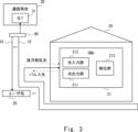
- the optical fiber sensing system includes an optical fiber 10 and an ONU 21.
- the ONU 21 is installed inside a user's house 20 which is a building and is connected to the optical fiber 10 .
- the optical fiber 10 is implemented by a PON line having one end connected to an ONU 21 provided inside the user's home 20 and the other end connected to an OLT 31 provided inside the communication station building 30 .
- FIG. 1 it is assumed that a plurality of user homes 20 exist, and the optical fiber 10 connected to the OLT 31 and the plurality of optical fibers 10 respectively connected to the ONUs 21 in the plurality of user homes 20 are connected. , are connected by an optical branch 40 .
- the number of user homes 20 is not limited to a plurality, and may be one or more.
- the ONU 21 functions as an optical fiber sensing device.
- the ONU 21 comprises an optical output section 211 and an optical input section 212 and further comprises a detection section 213 in order to realize the function of an optical fiber sensing device.
- the light output unit 211 outputs pulsed light to the optical fiber 10 .
- the light input unit 212 receives from the optical fiber 10 backscattered light generated as the pulsed light output from the light output unit 211 is transmitted through the optical fiber 10 .
- the optical fiber 10 since the optical fiber 10 is a PON line, it also transmits communication optical signals from the OLT 31 . Therefore, in order to enable the optical input unit 212 to receive only backscattered light, for example, the wavelength of the pulsed light output from the optical output unit 211 is shifted from the wavelength of the communication optical signal from the OLT 31 so that the optical input unit 212 can receive only the backscattered light. It is preferable to provide a filter before the .
- the detection unit 213 can detect vibration generated around the optical fiber 10 based on the backscattered light received from the optical fiber 10 by the light input unit 212 .
- the detector 213 can specify the intensity of the vibration based on the degree of change in the characteristics of the backscattered light. Based on the time difference between the time when the light output unit 211 outputs the pulsed light to the optical fiber 10 and the time when the light input unit 212 receives the backscattered light from the optical fiber 10, the detection unit 213 It is possible to specify the position (the distance of the optical fiber 10 from the ONU 21) where the backscattered light is generated. Therefore, when the detection unit 213 detects vibration based on the backscattered light, the detection unit 213 can identify the position where the backscattered light is generated and identify the identified position as the generation position where the vibration is generated. is. Further, the detection unit 213 can identify the time when the vibration occurred around the optical fiber 10 .
- the detection unit 213 detects vibration generated around the optical fiber 10
- the detection unit 213 converts vibration data indicating the vibration as sensing data based on the intensity of the vibration, the position of occurrence, the time of occurrence, and the like. It is possible to obtain
- the sound when sound is generated around the optical fiber 10, the sound is transmitted to the optical fiber 10, and the characteristics of the backscattered light transmitted through the optical fiber 10 change. Also, when the temperature around the optical fiber 10 changes, the characteristics of the backscattered light transmitted through the optical fiber 10 also change.
- the detection unit 213 can also detect the sound and temperature generated around the optical fiber 10 based on the backscattered light received from the optical fiber 10 by the light input unit 212 . Further, when the detection unit 213 detects sound generated around the optical fiber 10, the detection unit 213 can acquire acoustic data representing the sound as sensing data. Further, when detecting the temperature around the optical fiber 10, the detection unit 213 can acquire temperature data indicating the temperature as sensing data.
- the detection unit 213 transmits the sensing data acquired based on the backscattered light as described above as state information indicating the state of the surroundings of the optical fiber 10 .
- Sensing data transmitted as state information may include at least one of vibration data, acoustic data, and temperature data.
- the destination of the state information may be arbitrary, and may be, for example, a terminal of a user who owns or uses the user's house 20, a security company, the police, a fire station, or the like.
- the detection unit 213 may transmit the status information via its own line, or may transmit the status information via the optical fiber 10, which is a PON line. Further, the detection unit 213 may transmit sensing data as state information after performing A/D conversion processing.
- the light output unit 211 outputs pulsed light to the optical fiber 10 (step S11).
- the optical input unit 212 receives backscattered light for the pulsed light output by the optical output unit 211 from the optical fiber 10 (step S12).
- Sensing data may include at least one of vibration data, acoustic data, and temperature data.
- the ONU 21 side outputs pulsed light to the optical fiber 10 and receives backscattered light from the optical fiber 10, and outputs sensing data based on the backscattered light. It is transmitted as state information indicating the state of the surroundings of the optical fiber 10 .
- the ONU 21 side senses the surrounding state of the optical fiber 10 and transmits the sensing data as state information. Therefore, at the destination of the state information, it is possible to more accurately identify the residential land of the user's house 20 or an event in the vicinity of the residential land.
- the optical fiber 10 which is a PON line
- the optical fiber 10 is arranged so as to surround the residential area of the user's house 20, unlike the first embodiment described above. It is different in that it is connected to the ONU 21 after being drawn around.
- the optical fiber 10, which is a PON line is laid so as to surround the residential area of the user's house 20, compared with the above-described first embodiment, the residential area of the user's house 20 Or, it becomes possible to detect events around residential land in more detail.
- the second embodiment differs from the above-described first embodiment only in the laying method of the optical fiber 10, which is a PON line, and the rest of the configuration is the same. Therefore, the second embodiment is the same as the first embodiment described above in terms of the operation and effects other than those described above, and thus the description thereof will be omitted.
- the optical fiber sensing system according to the third embodiment is provided with an optical fiber 10A dedicated for sensing, and performs sensing using the optical fiber 10A, as compared with the first embodiment described above. and the point that the optical fiber 10A is routed so as to surround the residential area of the user's house 20 and then connected to the ONU 21.
- FIG. 4 the optical fiber sensing system according to the third embodiment is provided with an optical fiber 10A dedicated for sensing, and performs sensing using the optical fiber 10A, as compared with the first embodiment described above. and the point that the optical fiber 10A is routed so as to surround the residential area of the user's house 20 and then connected to the ONU 21.
- sensing is performed using the optical fiber 10A dedicated for sensing. 212 need not be configured to receive only backscattered light.
- the optical fiber 10A is laid so as to surround the residential area of the user's house 20, compared with the above-described first embodiment, the user's house 20's residential area or events in the vicinity of the residential area can be detected in more detail. become able to.
- the third embodiment differs from the first embodiment described above only in the optical fiber 10A used for sensing and the method of laying the optical fiber 10A, and the rest of the configuration is the same. Therefore, the third embodiment is the same as the first embodiment described above in terms of the operation and effects other than those described above, and therefore the description thereof will be omitted.
- the optical fiber sensing system according to the fourth embodiment differs from the above-described first embodiment in that an identification unit 214 is added to the ONU 21 .
- an event involving vibration for example, an abnormality
- the vibration corresponding to the event is transmitted to the optical fiber 10
- the characteristics of the backscattered light transmitted through the optical fiber 10 intensity
- the vibration data acquired by the detection unit 213 based on the backscattered light includes a unique vibration pattern in which the intensity of vibration, the position of vibration, the transition of fluctuation in frequency, etc. differ according to the event. ing. Therefore, by analyzing the dynamic change in the vibration pattern included in the vibration data, it is possible to identify the event that caused the vibration.
- the acoustic data acquired by the detector 213 based on the backscattered light includes a unique acoustic pattern corresponding to the event.
- the temperature data acquired by the detector 213 based on the backscattered light includes a unique temperature pattern corresponding to the event.
- the identifying unit 214 identifies an event occurring in or around the user's house 20 based on the sensing data acquired by the detecting unit 213 based on the backscattered light. Specifically, the identification unit 214 identifies an event that has occurred in or around a residential land using any of the methods described below. In addition, below, the example using vibration data as sensing data is demonstrated.
- the specifying unit 214 pre-stores the vibration pattern included in the vibration data of the vibration that actually occurred when the event occurred as a matching pattern in a memory (not shown) or the like. Keep
- the detection unit 213 acquires vibration data based on the backscattered light received from the optical fiber 10 by the light input unit 212 . Subsequently, the identification unit 214 compares the vibration pattern included in the vibration data acquired by the detection unit 213 with the matching pattern. If there is a matching pattern whose matching rate with the vibration pattern is equal to or higher than the threshold among the matching patterns, the specifying unit 214 determines that an event corresponding to the matching pattern occurs in or around the user's house 20. determine that it has occurred.
- the identification unit 214 prepares, for each event to be identified, a set of teacher data indicating the event and the vibration pattern included in the vibration data of the vibration that actually occurred when the event occurred. , each prepared set is input, a learning model is constructed in advance by a convolutional neural network (CNN), and stored in advance in a memory (not shown) or the like.
- CNN convolutional neural network
- the detection unit 213 acquires vibration data based on the backscattered light received from the optical fiber 10 by the light input unit 212 .
- the identifying unit 214 inputs the vibration pattern included in the vibration data acquired by the detecting unit 213 into the learning model.
- the identifying unit 214 obtains information on an event that occurred in or around the residential land of the user's house 20 as an output result of the learning model.
- the detecting unit 213 When the identifying unit 214 identifies an event that has occurred in the residential land of the user's house 20 or in the vicinity of the residential lot, the detecting unit 213 outputs an event occurring in the residential lot of the user's house 20 or in the vicinity of the residential lot as state information indicating the state of the surroundings of the optical fiber 10 . Sends the specific result of the event that occurred.
- sensing is performed using the optical fiber 10, which is a PON line, and the method of laying the optical fiber 10 is also the same as in FIG. not.
- the optical fiber 10, which is a PON line may be laid so as to surround the residential area of the user's house 20, as in the second embodiment shown in FIG.
- sensing may be performed using the optical fiber 10A dedicated to sensing, and the method of laying the optical fiber 10A may also be the same as in FIG.
- steps S21 and S22 similar to steps S11 and S12 in FIG. 2 are performed.
- the detection unit 213 acquires sensing data based on the backscattered light received by the light input unit 212, and the specifying unit 214 acquires the user's home 20 based on the sensing data acquired by the detection unit 213.
- the event that occurred in or around the residential land is specified (step S23). Event identification may be performed using either Method A or Method B described above.
- the detection unit 213 transmits, as state information indicating the state of the surroundings of the optical fiber 10, the identification result of the event occurring in or around the residential land of the user's house 20, which is identified by the identification unit 214 (step S24). ).
- an event occurring at or near the user's house 20 is specified, and the event is detected. is transmitted as state information indicating the state of the surroundings of the optical fiber 10 . Therefore, on the ONU 21 side, it is possible to more accurately identify an event occurring in or around the user's house 20 . In addition, the destination of the status information can obtain a more accurate event identification result.
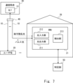
- the optical fiber sensing system according to the fifth embodiment has the same identification unit 214 provided in the ONU 21 in the user's home 20 as compared with the fourth embodiment described above. The difference is that the specifying unit 50 having the function is provided outside the user's home 20 .
- the identifying unit 50 has the same function as the identifying unit 214 according to the fourth embodiment, as described above. That is, the identifying unit 50 has a function of identifying an event occurring in or around the user's house 20 based on the sensing data acquired by the detecting unit 213 based on the backscattered light.
- the detection unit 213 when transmitting the state information indicating the surrounding state of the optical fiber 10, the detection unit 213 first acquires sensing data based on the backscattered light, and transmits the acquired sensing data to the specifying unit 50. do. Then, as a response to the sensing data, the detection unit 213 receives, from the identification unit 50, the identification result of an event occurring in or around the residential land of the user's house 20, and transmits the received identification result as state information.
- the detection unit 213 may use its own line for communication with the identification unit 50, or may use the optical fiber 10, which is a PON line. Further, the detection unit 213 may transmit the sensing data to the identification unit 50 after performing A/D conversion processing on the sensing data.
- the processing load on the ONU 21 can be reduced compared to the above-described fourth embodiment. Become.
- the fifth embodiment differs from the above-described fourth embodiment only in that the specifying unit 50 is provided outside the user's home 20, and the rest of the configuration is the same. Therefore, the fifth embodiment is similar to the above-described fourth embodiment in terms of the operation and effects other than those described above, and thus the description thereof will be omitted.
- the optical output unit 211, the optical input unit 212, and the detection unit 213 are provided inside the ONU 21 in the above-described embodiment, the present invention is not limited to this.
- the light output unit 211 is provided outside the ONU 21 , it is sufficient that the light output unit 211 outputs pulsed light to one end of the optical fiber 10 connected to the ONU 21 .
- the optical input unit 212 is provided outside the ONU 21 , it is sufficient that it receives backscattered light from one end of the optical fiber 10 connected to the ONU 21 .
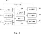
- the computer 60 includes a processor 61, a memory 62, a storage 63, an input/output interface (input/output I/F) 64, a communication interface (communication I/F) 65, and the like.
- the processor 61, the memory 62, the storage 63, the input/output interface 64, and the communication interface 65 are connected by data transmission paths for mutual data transmission/reception.
- the processor 61 is an arithmetic processing device such as a CPU (Central Processing Unit) or a GPU (Graphics Processing Unit).
- the memory 62 is, for example, RAM (Random Access Memory) or ROM (Read Only Memory).
- the storage 63 is a storage device such as a HDD (Hard Disk Drive), an SSD (Solid State Drive), or a memory card. Also, the storage 63 may be a memory such as a RAM or a ROM.
- a program is stored in the storage 63.
- This program includes instructions (or software code) that, when read into a computer, cause computer 60 to perform one or more of the functions in ONU 21 described above.
- the optical output unit 211 , the optical input unit 212 , the detection unit 213 , and the identification unit 214 in the ONU 21 described above may be realized by the processor 61 reading and executing a program stored in the storage 63 .
- the memory function in the ONU 21 described above may be realized by the memory 62 or the storage 63 .
- the above-described program may be stored in a non-transitory computer-readable medium or a tangible storage medium.
- computer readable media or tangible storage media may include RAM, ROM, flash memory, SSD or other memory technology, CD (Compact Disc)-ROM, DVD (Digital Versatile Disc), Blu-ray ( (registered trademark) discs or other optical disc storage, magnetic cassettes, magnetic tapes, magnetic disk storage or other magnetic storage devices.
- the program may also be transmitted on a transitory computer-readable medium or communication medium.
- transitory computer readable media or communication media include electrical, optical, acoustic, or other forms of propagated signals.
- the input/output interface 64 is connected to a display device 641, an input device 642, a sound output device 643, and the like.
- the display device 641 is a device that displays a screen corresponding to drawing data processed by the processor 61, such as an LCD (Liquid Crystal Display), a CRT (Cathode Ray Tube) display, or a monitor.
- the input device 642 is a device that receives an operator's operation input, and is, for example, a keyboard, mouse, touch sensor, or the like.
- the display device 641 and the input device 642 may be integrated and implemented as a touch panel.
- the sound output device 643 is a device, such as a speaker, that outputs sound corresponding to the sound data processed by the processor 61 .
- the communication interface 65 transmits and receives data to and from an external device.
- the communication interface 65 communicates with external devices via a wired communication path or a wireless communication path.
- (Appendix 1) an optical fiber one end of which is connected to an ONU (Optical Network Unit); an optical output unit that outputs pulsed light to the one end of the optical fiber; an optical input section for receiving backscattered light for the pulsed light from the one end of the optical fiber; a detection unit that transmits state information indicating a state around the optical fiber based on the backscattered light;
- a fiber optic sensing system comprising: (Appendix 2) The detection unit transmits the state information via a PON (Passive Optical Network) line.
- the optical fiber sensing system according to Appendix 1.
- the optical fiber is the PON line, The optical fiber sensing system according to Appendix 2.
- the optical fiber is an optical fiber dedicated to sensing, 3.
- the optical fiber is laid so as to surround the residential area of the building in which the ONU is installed. 5.
- the optical fiber sensing system according to any one of Appendices 1 to 4. (Appendix 6)
- the detection unit acquires sensing data indicating a state around the optical fiber based on the backscattered light, and transmits the sensing data as the state information. 6.
- the optical fiber sensing system according to any one of Appendices 1 to 5.
- the detection unit obtains sensing data indicating the state of the optical fiber surroundings based on the backscattered light
- the optical fiber sensing system comprises: further comprising an identification unit that identifies, based on the sensing data, an event that occurred in or around the building in which the ONU is installed; wherein the detection unit transmits a result of identifying the event by the identification unit as the state information; 6.
- the optical fiber sensing system according to any one of Appendices 1 to 5.
- a fiber optic sensing device comprising: (Appendix 9) The detection unit transmits the state information via a PON (Passive Optical Network) line.
- the fiber optic sensing device of claim 8. (Appendix 10) The optical fiber is the PON line, 9. The fiber optic sensing device of clause 9. (Appendix 11) The optical fiber is an optical fiber dedicated to sensing, 10.
- the optical fiber sensing device according to appendix 8 or 9.
- the optical fiber is laid so as to surround the residential area of the building in which the ONU is installed.
- the optical fiber sensing device according to any one of appendices 8 to 11.
- the detection unit acquires sensing data indicating a state around the optical fiber based on the backscattered light, and transmits the sensing data as the state information.
- the optical fiber sensing device according to any one of appendices 8-12.
- the detection unit obtains sensing data indicating the state of the optical fiber surroundings based on the backscattered light
- the fiber optic sensing device comprises: further comprising an identification unit that identifies, based on the sensing data, an event that occurred in or around the building in which the ONU is installed; wherein the detection unit transmits a result of identifying the event by the identification unit as the state information; 13.
- the optical fiber sensing device according to any one of appendices 8-12.
- a fiber optic sensing method comprising: (Appendix 16) In the transmitting step, the state information is transmitted via a PON (Passive Optical Network) line; 16.
- the optical fiber is the PON line, 17.
- the optical fiber is an optical fiber dedicated to sensing, 17.
- the optical fiber is laid so as to surround the residential area of the building in which the ONU is installed. 19.
- the optical fiber sensing method according to any one of Appendices 15 to 18. (Appendix 20) further comprising acquiring sensing data indicating a state of the optical fiber surroundings based on the backscattered light; In the transmitting step, the sensing data is transmitted as the state information. 20.
- Appendix 21 obtaining sensing data indicating the state of the optical fiber in its surroundings based on the backscattered light; a step of identifying an event that occurred in or around a building in which the ONU is installed, based on the sensing data; In the transmitting step, the result of identifying the event is transmitted as the state information.
- the optical fiber sensing method according to any one of Appendices 15 to 19.
Landscapes
- Engineering & Computer Science (AREA)
- Physics & Mathematics (AREA)
- Electromagnetism (AREA)
- Computer Networks & Wireless Communication (AREA)
- Signal Processing (AREA)
- Computing Systems (AREA)
- Arrangements For Transmission Of Measured Signals (AREA)
- Optical Transform (AREA)
Priority Applications (3)
| Application Number | Priority Date | Filing Date | Title |
|---|---|---|---|
| JP2023556021A JP7718501B2 (ja) | 2021-10-29 | 2021-10-29 | 光ファイバセンシングシステム、光ファイバセンシング機器、及び光ファイバセンシング方法 |
| US18/699,635 US20240405866A1 (en) | 2021-10-29 | 2021-10-29 | Optical fiber sensing system, optical fiber sensing device, and optical fiber sensing method |
| PCT/JP2021/040005 WO2023073914A1 (ja) | 2021-10-29 | 2021-10-29 | 光ファイバセンシングシステム、光ファイバセンシング機器、及び光ファイバセンシング方法 |
Applications Claiming Priority (1)
| Application Number | Priority Date | Filing Date | Title |
|---|---|---|---|
| PCT/JP2021/040005 WO2023073914A1 (ja) | 2021-10-29 | 2021-10-29 | 光ファイバセンシングシステム、光ファイバセンシング機器、及び光ファイバセンシング方法 |
Publications (1)
| Publication Number | Publication Date |
|---|---|
| WO2023073914A1 true WO2023073914A1 (ja) | 2023-05-04 |
Family
ID=86157620
Family Applications (1)
| Application Number | Title | Priority Date | Filing Date |
|---|---|---|---|
| PCT/JP2021/040005 Ceased WO2023073914A1 (ja) | 2021-10-29 | 2021-10-29 | 光ファイバセンシングシステム、光ファイバセンシング機器、及び光ファイバセンシング方法 |
Country Status (3)
| Country | Link |
|---|---|
| US (1) | US20240405866A1 (https=) |
| JP (1) | JP7718501B2 (https=) |
| WO (1) | WO2023073914A1 (https=) |
Cited By (1)
| Publication number | Priority date | Publication date | Assignee | Title |
|---|---|---|---|---|
| CN116599581A (zh) * | 2023-05-19 | 2023-08-15 | 煤炭科学技术研究院有限公司 | 光纤传感网络的可靠性评估方法、装置、设备及介质 |
Citations (5)
| Publication number | Priority date | Publication date | Assignee | Title |
|---|---|---|---|---|
| EP2141832A1 (en) * | 2008-07-03 | 2010-01-06 | Nokia Siemens Networks OY | Automatic topology discovery for passive optical networks |
| CN103222206A (zh) * | 2012-10-31 | 2013-07-24 | 华为技术有限公司 | 分支光纤的故障检测方法、装置及系统 |
| JP2015083936A (ja) * | 2013-10-25 | 2015-04-30 | 東日本電信電話株式会社 | 光ファイバ伝送路モニタ装置及び光ファイバ伝送路モニタシステム |
| WO2021070222A1 (ja) * | 2019-10-07 | 2021-04-15 | 日本電気株式会社 | 光ファイバセンシングシステム、光ファイバセンシング方法、及び光ファイバセンシング装置 |
| WO2021182507A1 (ja) * | 2020-03-13 | 2021-09-16 | 日本電気株式会社 | メンテナンスハッチの除去を特定するためのシステム及び使用方法 |
-
2021
- 2021-10-29 US US18/699,635 patent/US20240405866A1/en active Pending
- 2021-10-29 JP JP2023556021A patent/JP7718501B2/ja active Active
- 2021-10-29 WO PCT/JP2021/040005 patent/WO2023073914A1/ja not_active Ceased
Patent Citations (5)
| Publication number | Priority date | Publication date | Assignee | Title |
|---|---|---|---|---|
| EP2141832A1 (en) * | 2008-07-03 | 2010-01-06 | Nokia Siemens Networks OY | Automatic topology discovery for passive optical networks |
| CN103222206A (zh) * | 2012-10-31 | 2013-07-24 | 华为技术有限公司 | 分支光纤的故障检测方法、装置及系统 |
| JP2015083936A (ja) * | 2013-10-25 | 2015-04-30 | 東日本電信電話株式会社 | 光ファイバ伝送路モニタ装置及び光ファイバ伝送路モニタシステム |
| WO2021070222A1 (ja) * | 2019-10-07 | 2021-04-15 | 日本電気株式会社 | 光ファイバセンシングシステム、光ファイバセンシング方法、及び光ファイバセンシング装置 |
| WO2021182507A1 (ja) * | 2020-03-13 | 2021-09-16 | 日本電気株式会社 | メンテナンスハッチの除去を特定するためのシステム及び使用方法 |
Cited By (2)
| Publication number | Priority date | Publication date | Assignee | Title |
|---|---|---|---|---|
| CN116599581A (zh) * | 2023-05-19 | 2023-08-15 | 煤炭科学技术研究院有限公司 | 光纤传感网络的可靠性评估方法、装置、设备及介质 |
| CN116599581B (zh) * | 2023-05-19 | 2024-01-05 | 煤炭科学技术研究院有限公司 | 光纤传感网络的可靠性评估方法、装置、设备及介质 |
Also Published As
| Publication number | Publication date |
|---|---|
| JPWO2023073914A1 (https=) | 2023-05-04 |
| US20240405866A1 (en) | 2024-12-05 |
| JP7718501B2 (ja) | 2025-08-05 |
Similar Documents
| Publication | Publication Date | Title |
|---|---|---|
| US11747175B2 (en) | Utility pole location specifying system, utility pole location specifying apparatus, utility pole location specifying method, and non-transitory computer readable medium | |
| US7738787B2 (en) | Optical transmission line monitoring device, optical transmission line monitoring method, and computer program | |
| US12163815B2 (en) | Methods and systems for providing access to interferometric system data | |
| JP7235115B2 (ja) | 光ファイバセンシングシステム、光ファイバセンシング機器、及び異常判断方法 | |
| US20170211970A1 (en) | Method to increase the signal to noise ratio of distributed acoustic sensing by spatial averaging | |
| US12078769B2 (en) | Monitoring system, monitoring device, monitoring method, and non-transitory computer-readable medium | |
| CN116506013A (zh) | 光缆同路由检测方法、装置、系统、电子设备及存储介质 | |
| WO2026045842A1 (zh) | 一种光纤状态监测方法、装置、设备、介质及产品 | |
| JP7798113B2 (ja) | 光ファイバセンシングシステム、光ファイバセンシング方法、及びonu | |
| WO2024004119A1 (ja) | センシングシステム、センシング機器、及びセンシング方法 | |
| WO2023073914A1 (ja) | 光ファイバセンシングシステム、光ファイバセンシング機器、及び光ファイバセンシング方法 | |
| US20220291262A1 (en) | Optical fiber sensing system, optical fiber sensing equipment, and power outage detection method | |
| WO2021176581A1 (ja) | 監視システム、監視装置、及び監視方法 | |
| JP7444289B2 (ja) | 位置特定システム、振動発生器、及び位置特定方法 | |
| US20240353253A1 (en) | Detection system, detection apparatus, and detection method | |
| JP2023145498A (ja) | 特定システム、特定装置および特定方法 | |
| US20230070029A1 (en) | Detection system, detection device, and detection method | |
| JP7831616B2 (ja) | 光ファイバセンシングシステム、光ファイバセンシング機器、及び破断検知方法 | |
| CN115100842A (zh) | 红外遥控方法、装置、电子设备及可读存储介质 | |
| WO2023053184A1 (ja) | 光ファイバセンシングシステム、光ファイバセンシング機器、及び道路監視方法 | |
| JPWO2023073914A5 (https=) | ||
| US20240361178A1 (en) | Monitoring system, monitoring apparatus, and monitoring method | |
| US12618993B2 (en) | Relaying apparatus including a fiber sensing system for submarine use | |
| US20250015887A1 (en) | Monitoring in distributed acoustic sensing systems | |
| WO2023286147A1 (ja) | 流砂量観測システム、流砂量観測装置、流砂量観測方法、及びコンピュータ可読媒体 |
Legal Events
| Date | Code | Title | Description |
|---|---|---|---|
| 121 | Ep: the epo has been informed by wipo that ep was designated in this application |
Ref document number: 21962456 Country of ref document: EP Kind code of ref document: A1 |
|
| ENP | Entry into the national phase |
Ref document number: 2023556021 Country of ref document: JP Kind code of ref document: A |
|
| 122 | Ep: pct application non-entry in european phase |
Ref document number: 21962456 Country of ref document: EP Kind code of ref document: A1 |