WO2021182507A1 - メンテナンスハッチの除去を特定するためのシステム及び使用方法 - Google Patents
メンテナンスハッチの除去を特定するためのシステム及び使用方法 Download PDFInfo
- Publication number
- WO2021182507A1 WO2021182507A1 PCT/JP2021/009513 JP2021009513W WO2021182507A1 WO 2021182507 A1 WO2021182507 A1 WO 2021182507A1 JP 2021009513 W JP2021009513 W JP 2021009513W WO 2021182507 A1 WO2021182507 A1 WO 2021182507A1
- Authority
- WO
- WIPO (PCT)
- Prior art keywords
- optical fiber
- maintenance hatch
- determining
- backscattered light
- maintenance
- Prior art date
Links
- 238000012423 maintenance Methods 0.000 title claims abstract description 207
- 238000000034 method Methods 0.000 title claims abstract description 48
- 239000013307 optical fiber Substances 0.000 claims abstract description 195
- 230000002159 abnormal effect Effects 0.000 claims description 43
- 230000004044 response Effects 0.000 claims description 14
- 230000003287 optical effect Effects 0.000 claims description 11
- 239000000463 material Substances 0.000 claims description 9
- 230000008859 change Effects 0.000 description 33
- 238000007405 data analysis Methods 0.000 description 30
- 239000000835 fiber Substances 0.000 description 27
- 238000012806 monitoring device Methods 0.000 description 23
- 230000002547 anomalous effect Effects 0.000 description 17
- 238000004891 communication Methods 0.000 description 17
- 238000004458 analytical method Methods 0.000 description 9
- 238000010586 diagram Methods 0.000 description 8
- 238000001514 detection method Methods 0.000 description 7
- 238000003384 imaging method Methods 0.000 description 5
- 238000007689 inspection Methods 0.000 description 5
- XLYOFNOQVPJJNP-UHFFFAOYSA-N water Substances O XLYOFNOQVPJJNP-UHFFFAOYSA-N 0.000 description 5
- 238000004590 computer program Methods 0.000 description 4
- 238000012544 monitoring process Methods 0.000 description 4
- 230000008569 process Effects 0.000 description 4
- 238000012545 processing Methods 0.000 description 4
- 230000001965 increasing effect Effects 0.000 description 3
- 230000001902 propagating effect Effects 0.000 description 3
- 239000002184 metal Substances 0.000 description 2
- 239000004065 semiconductor Substances 0.000 description 2
- 230000005856 abnormality Effects 0.000 description 1
- 238000012937 correction Methods 0.000 description 1
- 230000003247 decreasing effect Effects 0.000 description 1
- 230000003111 delayed effect Effects 0.000 description 1
- 230000002708 enhancing effect Effects 0.000 description 1
- 230000006870 function Effects 0.000 description 1
- 238000009434 installation Methods 0.000 description 1
- 238000009413 insulation Methods 0.000 description 1
- 238000005259 measurement Methods 0.000 description 1
- 238000012986 modification Methods 0.000 description 1
- 230000004048 modification Effects 0.000 description 1
- 238000006467 substitution reaction Methods 0.000 description 1
- 238000011179 visual inspection Methods 0.000 description 1
Images


Classifications
-
- G—PHYSICS
- G01—MEASURING; TESTING
- G01D—MEASURING NOT SPECIALLY ADAPTED FOR A SPECIFIC VARIABLE; ARRANGEMENTS FOR MEASURING TWO OR MORE VARIABLES NOT COVERED IN A SINGLE OTHER SUBCLASS; TARIFF METERING APPARATUS; MEASURING OR TESTING NOT OTHERWISE PROVIDED FOR
- G01D5/00—Mechanical means for transferring the output of a sensing member; Means for converting the output of a sensing member to another variable where the form or nature of the sensing member does not constrain the means for converting; Transducers not specially adapted for a specific variable
- G01D5/26—Mechanical means for transferring the output of a sensing member; Means for converting the output of a sensing member to another variable where the form or nature of the sensing member does not constrain the means for converting; Transducers not specially adapted for a specific variable characterised by optical transfer means, i.e. using infrared, visible, or ultraviolet light
- G01D5/268—Mechanical means for transferring the output of a sensing member; Means for converting the output of a sensing member to another variable where the form or nature of the sensing member does not constrain the means for converting; Transducers not specially adapted for a specific variable characterised by optical transfer means, i.e. using infrared, visible, or ultraviolet light using optical fibres
-
- G—PHYSICS
- G01—MEASURING; TESTING
- G01D—MEASURING NOT SPECIALLY ADAPTED FOR A SPECIFIC VARIABLE; ARRANGEMENTS FOR MEASURING TWO OR MORE VARIABLES NOT COVERED IN A SINGLE OTHER SUBCLASS; TARIFF METERING APPARATUS; MEASURING OR TESTING NOT OTHERWISE PROVIDED FOR
- G01D5/00—Mechanical means for transferring the output of a sensing member; Means for converting the output of a sensing member to another variable where the form or nature of the sensing member does not constrain the means for converting; Transducers not specially adapted for a specific variable
- G01D5/26—Mechanical means for transferring the output of a sensing member; Means for converting the output of a sensing member to another variable where the form or nature of the sensing member does not constrain the means for converting; Transducers not specially adapted for a specific variable characterised by optical transfer means, i.e. using infrared, visible, or ultraviolet light
- G01D5/32—Mechanical means for transferring the output of a sensing member; Means for converting the output of a sensing member to another variable where the form or nature of the sensing member does not constrain the means for converting; Transducers not specially adapted for a specific variable characterised by optical transfer means, i.e. using infrared, visible, or ultraviolet light with attenuation or whole or partial obturation of beams of light
- G01D5/34—Mechanical means for transferring the output of a sensing member; Means for converting the output of a sensing member to another variable where the form or nature of the sensing member does not constrain the means for converting; Transducers not specially adapted for a specific variable characterised by optical transfer means, i.e. using infrared, visible, or ultraviolet light with attenuation or whole or partial obturation of beams of light the beams of light being detected by photocells
- G01D5/353—Mechanical means for transferring the output of a sensing member; Means for converting the output of a sensing member to another variable where the form or nature of the sensing member does not constrain the means for converting; Transducers not specially adapted for a specific variable characterised by optical transfer means, i.e. using infrared, visible, or ultraviolet light with attenuation or whole or partial obturation of beams of light the beams of light being detected by photocells influencing the transmission properties of an optical fibre
- G01D5/35338—Mechanical means for transferring the output of a sensing member; Means for converting the output of a sensing member to another variable where the form or nature of the sensing member does not constrain the means for converting; Transducers not specially adapted for a specific variable characterised by optical transfer means, i.e. using infrared, visible, or ultraviolet light with attenuation or whole or partial obturation of beams of light the beams of light being detected by photocells influencing the transmission properties of an optical fibre using other arrangements than interferometer arrangements
- G01D5/35354—Sensor working in reflection
- G01D5/35358—Sensor working in reflection using backscattering to detect the measured quantity
-
- G—PHYSICS
- G01—MEASURING; TESTING
- G01K—MEASURING TEMPERATURE; MEASURING QUANTITY OF HEAT; THERMALLY-SENSITIVE ELEMENTS NOT OTHERWISE PROVIDED FOR
- G01K11/00—Measuring temperature based upon physical or chemical changes not covered by groups G01K3/00, G01K5/00, G01K7/00 or G01K9/00
- G01K11/32—Measuring temperature based upon physical or chemical changes not covered by groups G01K3/00, G01K5/00, G01K7/00 or G01K9/00 using changes in transmittance, scattering or luminescence in optical fibres
-
- G—PHYSICS
- G01—MEASURING; TESTING
- G01M—TESTING STATIC OR DYNAMIC BALANCE OF MACHINES OR STRUCTURES; TESTING OF STRUCTURES OR APPARATUS, NOT OTHERWISE PROVIDED FOR
- G01M11/00—Testing of optical apparatus; Testing structures by optical methods not otherwise provided for
- G01M11/08—Testing mechanical properties
- G01M11/083—Testing mechanical properties by using an optical fiber in contact with the device under test [DUT]
- G01M11/086—Details about the embedment of the optical fiber within the DUT
-
- G—PHYSICS
- G01—MEASURING; TESTING
- G01M—TESTING STATIC OR DYNAMIC BALANCE OF MACHINES OR STRUCTURES; TESTING OF STRUCTURES OR APPARATUS, NOT OTHERWISE PROVIDED FOR
- G01M11/00—Testing of optical apparatus; Testing structures by optical methods not otherwise provided for
- G01M11/30—Testing of optical devices, constituted by fibre optics or optical waveguides
- G01M11/31—Testing of optical devices, constituted by fibre optics or optical waveguides with a light emitter and a light receiver being disposed at the same side of a fibre or waveguide end-face, e.g. reflectometers
- G01M11/3109—Reflectometers detecting the back-scattered light in the time-domain, e.g. OTDR
-
- G—PHYSICS
- G08—SIGNALLING
- G08B—SIGNALLING OR CALLING SYSTEMS; ORDER TELEGRAPHS; ALARM SYSTEMS
- G08B13/00—Burglar, theft or intruder alarms
- G08B13/02—Mechanical actuation
- G08B13/14—Mechanical actuation by lifting or attempted removal of hand-portable articles
- G08B13/1481—Mechanical actuation by lifting or attempted removal of hand-portable articles with optical detection
-
- G—PHYSICS
- G08—SIGNALLING
- G08B—SIGNALLING OR CALLING SYSTEMS; ORDER TELEGRAPHS; ALARM SYSTEMS
- G08B21/00—Alarms responsive to a single specified undesired or abnormal condition and not otherwise provided for
- G08B21/18—Status alarms
-
- G—PHYSICS
- G01—MEASURING; TESTING
- G01K—MEASURING TEMPERATURE; MEASURING QUANTITY OF HEAT; THERMALLY-SENSITIVE ELEMENTS NOT OTHERWISE PROVIDED FOR
- G01K13/00—Thermometers specially adapted for specific purposes
- G01K13/12—Thermometers specially adapted for specific purposes combined with sampling devices for measuring temperatures of samples of materials
Definitions
- This disclosure relates to a system and usage for identifying the removal of maintenance hatches.
- the method according to the first embodiment is a method of detecting the removal of the maintenance hatch, which is a step of transmitting an optical pulse along the optical fiber, in which the first portion of the optical fiber is attached to the maintenance hatch.
- the first step of the optical fiber is based on a close step, a step of detecting backward scattered light from the optical fiber using a sensor, and a comparison of the detected backward scattered light with a trained model. Includes a step of determining information related to part 1 and a step of identifying whether the maintenance hatch has been removed based on the determined information.
- the system according to the second embodiment is a system for detecting the removal of the maintenance hatch, which detects a computer-readable recording medium configured to store instructions and backscattered light data from the optical fiber.
- a sensor configured to: The detected backscattered light data is received, and the information related to the first part of the optical fiber is determined based on the comparison between the detected backscattered light data and the trained model. It comprises a processor that is configured to execute the instructions for identifying whether the maintenance hatch has been removed based on the determined information.
- the computer-readable recording medium is a computer-readable recording medium configured to store instructions, the instructions to the processor when executed by the processor.
- the backscattered light data is received based on the backscattered light detected from the optical fiber having the first part close to the maintenance hatch, and based on the comparison between the received backscattered light data and the trained model.
- the information related to the first portion of the optical fiber is determined, and based on the determined information, it is determined whether or not the maintenance hatch has been removed.
- FIG. 5 is a schematic diagram of a system for monitoring the removal of maintenance hatches according to some embodiments. It is a flowchart of the method of specifying the removal of the maintenance hatch which concerns on some embodiments. It is a graph of the detected backscattered light data which concerns on some embodiments. It is a graph of frequency vs. amplitude based on the detected backscattered light data which concerns on some embodiments. It is a graph of frequency vs. amplitude based on the detected backscattered light data which concerns on some embodiments. It is a graph of frequency vs. amplitude based on the detected backscattered light data which concerns on some embodiments. It is a graph of frequency vs. amplitude based on the detected backscattered light data which concerns on some embodiments.
- FIG. 6 is a graph of intensity vs. distance provided by the arrangement of FIG. 6A according to some embodiments.
- FIG. 5 is a layout of an upper opening of an optical fiber without a maintenance hatch (maintenance cover) according to some embodiments.
- FIG. 5 is a graph of intensity vs. distance provided by the arrangement of FIG. 7A according to some embodiments.
- FIG. 5 is a layout of an embedded optical fiber including an opening covered by a maintenance hatch according to some embodiments.
- FIG. 5 is a graph of temperature vs. distance provided by the arrangement of FIG. 8A according to some embodiments.
- FIG. 5 is a layout of an embedded optical fiber including an opening without a maintenance hatch according to some embodiments.
- 9 is a graph of temperature vs. distance provided by the arrangement of FIG. 9A according to some embodiments.
- 9 is a graph of temperature vs. distance provided by the arrangement of FIG. 9A according to some embodiments.
- 9 is a graph of temperature vs. distance provided by the arrangement of FIG. 9A according to some embodiments.
- FIG. 5 is a schematic diagram of a system for identifying the removal of maintenance hatches according to some embodiments.
- first and second features are formed in direct contact. It may also include embodiments in which additional features may be formed between the first and second features so that the first and second features do not come into direct contact.
- present disclosure may repeat reference numbers and / or letters in various examples. This repetition is for brevity and clarity and does not, by itself, define the relationships between the various embodiments and / or forms discussed.
- Identifying when the maintenance hatch, such as the manhole cover, was removed helps to quickly replace the maintenance hatch and reduces the risk of public facilities covered by the maintenance hatch. Rapid identification of maintenance hatch removal also helps increase the likelihood of identifying whether a maintenance hatch has been stolen and, if so, who stolen it.
- the present disclosure provides a system for identifying whether a maintenance hatch has been removed based on measurements of backscattered light data from an optical fiber.
- Fiber optics are used for communication between different pieces of equipment and are often already present near maintenance hatches. As a result, the cost of monitoring the removal of maintenance hatches is significantly reduced.
- FIG. 1 is a schematic view of a sensor system (sometimes referred to simply as a system) 100 according to some embodiments.
- the sensor system 100 includes a monitoring device 111 that communicates with the sensor 112.
- the sensor 112 includes an optical time domain reflectometer (OTDR) or other suitable sensor.
- the sensor system 100 further includes an optical fiber 121 connected to the sensor 112.
- the sensor 112 receives backscattered light from the optical fiber 121, and the backscattered light is photoelectrically converted into a signal called backscattered light data used in the subsequent analysis.
- the optical fiber 121 can be used for information transmitted between communication facilities.
- the optical fiber 121 is arranged near the maintenance hatch 130.
- Optical pulses are transmitted along the optical fiber 121.
- Backscattered light is generated as the light pulse propagates along the optical fiber 121.
- the sensor 112 is configured to detect the backscattered light and transmit a signal based on the detected backscattered light to the monitoring device 111.
- the maintenance hatch 130 is on the sidewalk. In some embodiments, the maintenance hatch 130 is on the road. In some embodiments, the maintenance hatch 130 is on the ground. In some embodiments, the optical fiber 121 is covered by a maintenance hatch 130. In some embodiments, the fiber optic 121 is offset from the maintenance hatch 130, but is sufficiently close to the maintenance hatch 130 that it is affected by vibrations associated with the removal of the maintenance hatch 130.
- the backscattered light from the optical fiber 121 is affected by the environment in the vicinity of the optical fiber 121.
- ground vibrations affect backscattered light produced by light pulses.
- the vibration is caused by the pedestrian walking near the optical fiber 121, the vehicle passing near the optical fiber 121, and the removal of the maintenance hatch near the optical fiber 121.
- the sound waves incident on the optical fiber 121 also affect the backscattered light generated during the propagation of the optical pulse.
- the temperature of the optical fiber 121 also affects the backscattered light.
- the monitoring device 111 can also detect an abnormality in the environment surrounding the optical fiber 121 by detecting backscattered light and applying a trained (learned) analysis model.
- optical pulses assists in the analysis of backscattered light to determine at which point along the optical fiber 121 the anomaly occurred. Based on the velocity of the light pulse moving along the optical fiber and the timing of the detected backscattered light, the distance traveled by the light pulse before the backscattering of the light can be determined. This helps the monitoring device 111 determine both the location of the anomaly and the timing of the anomaly.
- FIG. 2 is a schematic diagram of a system 200 for monitoring the removal of maintenance hatches according to some embodiments.
- the system 200 includes a first communication facility 210 and a second communication facility 220.
- the optical fiber 230 connects the first communication equipment 210 with the second communication equipment 220.
- the maintenance hatch 240 is located close to the optical fiber 230.
- the optical fiber 230 is covered by a maintenance hatch 240.
- the fiber optic 230 is offset from the maintenance hatch 240.
- the sensor 250 is connected to the optical fiber 230.
- the sensor 250 is configured to receive backscattered light data from the optical fiber 230.
- the data analysis device 260 is communicating with the sensor 250.
- the monitoring device 270 is communicating with the data analysis device 260.
- the optical fiber 230 is configured to transmit an information signal between the first communication equipment 210 and the second communication equipment 220.
- the optical fiber 230 is a multimode optical fiber.
- the optical fiber 230 is a single mode optical fiber.
- the optical fiber 230 is at least partially embedded in the ground.
- the optical fiber 230 is in a conduit.
- the optical fiber 230 is in a sewer pipe or in another public facility passage.
- the maintenance hatch 240 covers the access point to public facilities.
- the maintenance hatch 240 includes a manhole cover.
- the maintenance hatch 240 includes a grid, a cleanout cover, a drain cover, or other cover suitable for public facilities.
- the maintenance hatch 240 is sufficiently close to the optical fiber 230 so that the removal of the maintenance hatch 240 affects the surrounding environment in the vicinity of the optical fiber 230.
- the ambient environment in the vicinity of the optical fiber 230 is affected by the vibrations caused by removing the maintenance hatch 240.
- the ambient environment in the vicinity of the optical fiber 230 is affected by varying the ability of sound waves incident on the optical fiber 230.
- the ambient environment in the vicinity of the fiber optic 230 is affected by allowing greater temperature variation in the fiber optic 230. In some embodiments, the ambient environment in the vicinity of the optical fiber 230 is affected by allowing moisture to come into contact with the optical fiber 230.
- FIG. 2 includes a single maintenance hatch 240 for simplicity. In some embodiments, the system comprises a plurality of maintenance hatches 240.
- the sensor 250 is configured to receive backscattered light data from the optical fiber 230, including backscattered light data associated with changes in the ambient environment near the optical fiber related to the presence or absence of the maintenance hatch 240.
- the sensor 250 is configured to detect backscattered light data relating to light propagating from the first communication facility 210 to the second communication facility 220.
- the sensor is configured to detect backscattered light data about light propagating from the second communication facility 220 to the first communication facility 210.
- the system 200 is configured to receive backscattered light data about light propagating from the second communication facility 220 to the first communication facility 210 (not shown). )including.
- the sensor 250 comprises an OTDR or other suitable sensor.
- the senor 250 is housed in a first communication facility 210. In some embodiments, the sensor 250 is separate from the first communication facility 210. In some embodiments, the sensor 250 is housed in a second communication facility 220. In some embodiments, the sensor 250 is similar to the sensor 112 (FIG. 1).
- the data analysis device 260 is configured to receive backscattered light data from the sensor 250.
- the data analysis device 260 includes at least a processor for performing the functions of the data analysis device 260.
- the data analysis device 260 is configured to analyze the backscattered light data to determine if the backscattered light data shows any anomalies.
- the data analysis device 260 communicates with the sensor 250 via a wireless network. In some embodiments, a wired connection exists between the data analysis device 260 and the sensor 250.
- the data analysis device 260 is configured to receive backscattered light data from all sensors.
- the data analysis device 260 is configured to receive backscattered light data from all fewer sensors.
- the data analysis device 260 is similar to the monitoring device 111 (FIG. 1).
- the data analysis device 260 uses a trained model (trained model) to analyze backscattered light data.
- the trained model is provided to the data analysis device 260 by an external device.
- the trained model is built by the data analysis device 260.
- the trained model is built using teaching data.
- the teacher data includes information on the normal and abnormal states of the backscattered light data.
- the normal state includes backscattered light data of a sample showing the state of the optical fiber 230 when the maintenance hatch 240 is properly positioned.
- the anomalous condition includes sample backscattered light data showing the condition of the optical fiber 230 when the maintenance hatch 240 is removed.
- the state of the fiber optic 230 is associated with at least one of vibrations of the fiber optic 230, sound waves incident on the fiber optic 230, or temperature fluctuations of the fiber optic 230.
- the teacher data includes predictive data or computer-generated data.
- the teacher data includes empirical data.
- the teacher data includes a combination of predictive or computer-generated data and empirical data.
- the data analysis device 260 compares the actual data received from the sensor 250 with the trained model to determine whether the state of the optical fiber 230 is normal or abnormal.
- the data analysis device 260 is configured to receive meteorological data from an external device to assist in determining the anomalous state of the optical fiber 230.
- the comparison results are transferred to the monitoring device 270.
- the monitoring device 270 is configured to receive the analysis result by the data analysis device 260 and provide the result to the user.
- the surveillance device 270 includes at least a display and a processor. In some embodiments, the surveillance device 270 communicates wirelessly with the data analysis device 260. In some embodiments, the surveillance device 270 has a wired connection to the data analysis device 260.
- the monitoring device 270 displays a warning according to the analysis (analysis result) from the data analysis device 260 indicating the abnormal state of the optical fiber 230.
- the warning includes text, voice, or graphic (image) data.
- the warning includes information related to the location of the anomalous state of the optical fiber 230.
- the warning includes the timing of the start of an abnormal state of the optical fiber 230.
- the monitoring device 270 displays the normal state according to the analysis (analysis result) from the data analysis device 260 indicating the normal state of the optical fiber 230.
- the surveillance device 270 is connected to at least one local imaging device for taking an image of the area including the maintenance hatch 240. In some embodiments, the surveillance device 270 captures an image from a local imaging device associated with the maintenance hatch 240 in response to receiving data indicating an abnormal condition of the optical fiber 230 at the location of the maintenance hatch 240. indicate. In some embodiments, the surveillance device 270 selects an image received from the local imaging device based on the determined start timing of the anomalous state of the optical fiber 230 for display to the user.
- the monitoring device 270 is omitted.
- the comparison result is sent to the user in response to the determination of the abnormal state of the optical fiber 230.
- the alert is sent to a mobile device accessible by the user.
- the warning includes text, voice, or graphic (image) data.
- the ability to accurately and instantly detect the timing and position of the abnormal state of the optical fiber 230 allows the system 200 to quickly determine if the maintenance hatch 240 has been removed. This facilitates quick replacement of the maintenance hatch 240 and reduces the risk of damage to public facilities. Furthermore, the combination of the detected anomalous condition of the fiber optic 230 with the imaging of the maintenance hatch 240 enhances the ability to identify the theft of the maintenance hatch 240, which can lead to the capture of thieves and the deterrence of future theft. .. Combining the detected abnormal state of the optical fiber 230 with the imaging of the maintenance hatch 240 is also useful for identifying false positives in the abnormal detection data. These false positives can be fed back to the trained model used by the data analysis device 260 to improve the accuracy of the trained model. Even in some embodiments that do not include the monitoring device 270, if the inspection of the maintenance hatch 240 following the display of the abnormal condition of the optical fiber 230 indicates that the maintenance hatch 240 remains in place, the information is trained. You can feed back to the finished model.
- the data analysis device 260 or the monitoring device 270 can cross-reference the scheduled maintenance with the detected anomalous state of the optical fiber 230. By cross-referencing the scheduled maintenance with the detected anomalous condition of the fiber optic 230, unnecessary warnings to the user regarding the removal of the maintenance hatch 240 are reduced or avoided.
- FIG. 3 is a flowchart of the method 300 for specifying the removal of the maintenance hatch according to some embodiments.
- an optical pulse is transmitted along the optical fiber, for example, the optical fiber 121 (FIG. 1) or the optical fiber 230 (FIG. 2).
- the optical fiber comprises a multimode optical fiber.
- the optical fiber comprises a single mode optical fiber.
- the optical fiber is covered by a maintenance hatch.
- the optical fiber is offset from the maintenance hatch. Since the optical fiber is close enough to the maintenance hatch, removal of the maintenance hatch will affect the surrounding environment near a portion of the optical fiber.
- backscattered light data is detected from the optical fiber.
- Backscattered light data is the result of reflections within the optical fiber, such as Rayleigh reflections. When the state near the optical fiber changes, the difference in backscattered light data can be detected.
- backscattered light data is detected using an OTDR.
- backscattered light data is detected using sensor 112 (FIG. 1) or sensor 250 (FIG. 2).
- the backscattered light data is analyzed to determine whether or not an abnormal state exists in the vicinity of the optical fiber.
- the anomalous condition is detectable due to vibration of the optical fiber, sound waves incident on the optical fiber, or at least one of temperature fluctuations in the optical fiber.
- the backscattered light data is analyzed using a comparison of the backscattered light data with the trained model.
- backscattered light data is analyzed using monitoring device 111 (FIG. 1).
- backscattered light data is analyzed using a data analysis device 260 (FIG. 2).
- method 300 proceeds to any step 320, depending on the determination that no abnormal condition is detected.
- the user is informed that it is in a normal state.
- the normal state is reported to the user by a monitoring terminal, such as the monitoring device 270.
- normal conditions are reported to the user using a mobile device accessible by the user.
- normal conditions are reported using text, voice, or graphic (image) information.
- the optional step 320 is omitted.
- the optional step 320 is omitted in situations where the user is primarily involved in identifying maintenance hatch removal. If any step 320 is omitted, the normal state is not reported to the user.
- the method 300 proceeds to step 325 according to the determination that the abnormal state has been detected.
- step 325 the position of the abnormal state along the optical fiber is determined.
- the location of the anomaly along the optical fiber is based on the timing of the backscattered light data detected for the corresponding transmit pulse from step 305.
- the position of the maintenance hatch that is presumed to be the cause of the abnormal state is identified.
- the location of the anomaly is determined using the processor.
- the location of the abnormal condition is determined by monitoring device 111 (FIG. 1).
- the location of the anomalous state is determined by the sensor 250 (FIG. 2).
- the maintenance hatch can be quickly replaced to reduce the risk of damage to the underlying public facilities.
- the timing of starting an abnormal state along the optical fiber is determined.
- the timing of the onset of anomalous conditions along the optical fiber is based on when the detected backscattered light data was received.
- the timing of the start of the abnormal condition By determining the timing of the start of the abnormal condition, the time when the maintenance hatch is removed is specified.
- the timing of the start of an abnormal condition is determined using the processor.
- the timing of the start of the abnormal state is determined by the monitoring device 111 (FIG. 1).
- the timing of the start of the abnormal condition is determined by the sensor 250 (FIG. 2). Detecting the timing of the onset of anomalous conditions increases the chances of identifying potential thieves.
- any step 330 is omitted.
- optional step 330 is omitted.
- the detection of the abnormal state may be significantly delayed. This is because the detection of anomalous conditions is based on temperature differences (or expected temperature differences) that, in some cases, do not occur over the hours following removal of the maintenance hatch.
- the sound wave source is removed a considerable amount of time after the maintenance hatch is first removed. There is a high possibility that it will pass through the maintenance hatch. Omission of any step 330 helps reduce the processing load for analysis when the timing of the start of the abnormal state is unlikely to be useful information.
- a warning of an abnormal state is transmitted to the user.
- the warning includes information about the location and / or timing of the abnormal condition.
- the warning includes text, voice, or graphic (image) data.
- the warning is combined with an image of the area containing the maintenance hatch associated with the detected anomaly.
- the warning is communicated using the surveillance device 270 (FIG. 2).
- the alert is transmitted to a mobile device accessible by the user.
- the warning is communicated with information related to the scheduled maintenance associated with the maintenance hatch to mitigate or avoid unnecessary concerns about the removal of the maintenance hatch.
- a further step is included in method 300.
- false positives are fed back to the trained model to improve the accuracy of the trained model.
- at least one step is omitted.
- any step 330 is omitted as described above.
- the process sequence of method 300 is modified.
- any step 320 is performed prior to step 315 such that the normal state is reported until an abnormal state is detected.
- Method 300 is useful for enhancing the ability to accurately and quickly detect the timing and / or position of an abnormal state of an optical fiber. This facilitates quick replacement of maintenance hatches and reduces the risk of damage to public facilities.
- FIG. 4 is a graph 400 of detected backscattered light data according to some embodiments.
- Graph 400 includes amplitudes at specific detected frequencies over time for backscattered light data from optical fibers.
- the graph 400 includes an increase in the amplitude of the detected frequencies in the time range of about 15 seconds to about 60 seconds as compared to the rest of the graph 400.
- This type of data can be used, for example, to determine the occurrence of vibrations in the ambient environment surrounding an optical fiber.
- FIG. 5A is a graph 500 of frequency vs. amplitude based on detected backscattered light data according to some embodiments.
- the graph 500 is generated by using a Fourier transform on the information collected in the backscattered light data.
- Graph 500 includes plot 510. Small changes in plot 510 indicate small vibrational changes at different frequencies.
- the first frequency F1 is a frequency at which the vehicle is likely to cause vibration of the optical fiber. In some embodiments, the first frequency F1 is at about 50 hertz (Hz).
- the second frequency F2 is a frequency at which the removal of the maintenance hatch is likely to cause vibration of the optical fiber. In some embodiments, the second frequency F2 is at about 70 Hz.
- removal of different maintenance hatches results in the generation of different frequencies.
- the frequency produced by the removal of the maintenance hatch depends on the material of the maintenance hatch, the type of installation of the maintenance hatch in the opening, the size of the maintenance hatch, and the shape of the maintenance hatch.
- the use of the trained model in combination with information related to the type of maintenance hatch at different locations along the fiber optics improves the accuracy of detection of maintenance hatch removal.
- Plot 510 does not contain significant peaks in either the first frequency F1 or the second frequency F2. This indicates a normal state.
- the monitoring device 111 (FIG. 1) or the data analysis device 260 (FIG. 2) determines that the optical fiber is in a normal state, depending on the generation of the plot, such as plot 510.
- FIG. 5B is a graph 500'of frequency vs. amplitude based on detected backscattered light data according to some embodiments.
- the graph 500' is generated by using the Fourier transform on the information collected in the backscattered light data.
- Graph 500' includes plot 510'.
- plot 510' contains a peak at the first frequency F1.
- the peak at the first frequency F1 indicates the passage of the vehicle.
- the peak at the first frequency does not indicate the removal of the maintenance hatch. Therefore, plot 510'will indicate a normal state.
- the monitoring device 111 (FIG. 1) or the data analysis device 260 (FIG. 2) determines that the optical fiber is in a normal state.
- FIG. 5C is a graph 500 "of frequency vs. amplitude based on detected backscattered light data according to some embodiments.
- the graph 500 was collected with backscattered light data. Generated by using a Fourier transform on the information.
- Graph 500 “includes plot 510".
- plot 510 "contains a peak at the second frequency F2.
- the peak at the second frequency F2 indicates the removal of the maintenance hatch. Therefore, plot 510" indicates an abnormal condition. Will show.
- the monitoring device 111 (FIG. 1) or the data analysis device 260 (FIG. 2) determines that the optical fiber is in an abnormal state, depending on the generation of the plot, such as plot 510 ".
- timing backscattered light data such as Graph 400 (FIG. 4)
- anomalous condition detection such as Plot 510 ”(FIG. 5C)
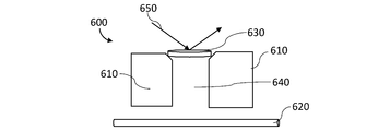
- FIG. 6A is a diagram of an arrangement 600 of the maintenance hatch 630 covering the upper opening 640 of the optical fiber 620 according to some embodiments.
- Arrangement 600 includes a maintenance hatch 630 that covers the opening 640 of the ground 610.
- the opening 640 is in a sewer pipe or other public facility conduit.
- the optical fiber 620 is below the maintenance hatch 630 and is protected by the maintenance hatch 630 from the environment on the opposite side of the maintenance hatch 630. Sound waves 650 from the environment opposite the maintenance hatch are generated by a sound source (not shown).
- the maintenance hatch 630 reflects or diverts a significant portion of the sound wave 650, as can be seen from the arrangement 600. As a result, a small amount of sound wave 650 is incident on (or not at all) the optical fiber 620.
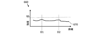
- FIG. 6B is an intensity vs. distance graph 660 provided by the arrangement of FIG. 6A according to some embodiments.
- Graph 660 includes plot 670.
- Plot 670 shows a slight change in the intensity of sound waves incident along the optical fiber 620. All changes in the intensity of the sound wave along the optical fiber 620 are below the intensity threshold Is.
- the intensity of the sound wave incident on the optical fiber 620 is determined by the depth of the optical fiber 620, the size of the opening 640, the material of the ground 610, and the shape and orientation of the opening 640. In some embodiments, the user utilizes these factors to set the intensity threshold Is.
- the processor eg, monitoring device 111 (FIG. 1) or data analysis device 260 (FIG.
- Graph 660 includes a first distance D1 indicating the position of the maintenance hatch 630 along the optical fiber 620.
- Graph 660 further includes a second distance D2 indicating the location of a second maintenance hatch (not shown) along the optical fiber 620.
- the distances D1 and D2 are distances from a sensor, for example, sensor 112 (FIG. 1) or sensor 250 (FIG. 2).
- Plot 670 shows that both the maintenance hatch 630 at distance D1 and the second maintenance hatch at distance D2 are in normal condition.
- FIG. 7A is a diagram of the arrangement 700 of the upper opening 740 of the optical fiber 720 without the maintenance hatch according to some embodiments.
- arrangement 700 does not include a maintenance hatch, i.e., the maintenance hatch is removed from above the opening 740 of the ground 710.
- the opening 740 is in a sewer pipe or other public facility conduit.
- the fiber optic 720 is below the position where the maintenance hatch should be located, but is exposed to the environment outside the opening 740. Sound waves 750 from the environment outside the aperture can propagate through the aperture 740 and enter the optical fiber 720.
- FIG. 7B is a graph 760 of intensity vs. distance provided by the arrangement of FIG. 7A according to some embodiments.
- Graph 760 includes plot 770.
- plot 770 includes an intensity spike at distance D1 indicating that the sound wave 750 is not blocked by the maintenance hatch.
- the intensity peak at the distance D1 exceeds the intensity threshold Is. Therefore, plot 770 shows that the maintenance hatch at distance D1 has been removed.
- plot 770 does not include peaks at distance D2. Therefore, plot 770 shows that the maintenance hatch at distance D2 remains above the fiber optic 720.
- Plot 770 shows that the maintenance hatch at distance D1 is in an abnormal state and the maintenance hatch at distance D2 is in a normal state.
- FIG. 8A is a diagram of an arrangement 800 of an embedded optical fiber 820 including an opening 840 covered by a maintenance hatch 830 according to some embodiments.
- Arrangement 800 includes a maintenance hatch 830 that covers the opening 840 of the ground 810.
- the opening 840 is in a sewer pipe or other public facility conduit.
- the optical fiber 820 is located below the maintenance hatch 830 and is protected by the maintenance hatch 830 from the environment on the opposite side of the maintenance hatch 830.
- the portion of the optical fiber 820 embedded in the ground 810 or embedded in the conduit embedded in the ground 810 has a substantially uniform temperature both during the day and at night because the temperature of the ground 810 is substantially uniform.
- the portion of the optical fiber 820 in the opening 840 shows a change in temperature due to a change in air temperature.
- daytime temperatures are generally higher than nighttime temperatures. Therefore, the portion of the optical fiber 820 within the opening 840 is expected to exhibit temperature fluctuations from day to night.
- the maintenance hatch 830 covers the opening 840, heat is reflected by the maintenance hatch 830 during the day and the maintenance hatch 830 insulates the opening 840 at night, so that the temperature of the portion of the optical fiber 820 in the opening 840 The magnitude of the variation is reduced compared to when the optical fiber is exposed.
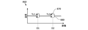
- FIG. 8B is a graph 860 of temperature vs. intensity provided by the arrangement of FIG. 8A according to some embodiments.
- Graph 860 includes a plot 870 for temperatures measured during the day and a plot 880 for temperatures measured at night. Both plot 870 and plot 880 show that the portion of fiber optic 820 embedded in the ground 810 maintains a substantially uniform temperature during both daytime and nighttime.
- Graph 860 includes a first distance D1 indicating the position of the maintenance hatch 830 along the optical fiber 820.
- Graph 860 further includes a second distance D2 indicating the location of a second maintenance hatch (not shown) along the optical fiber 820.
- the distances D1 and D2 are distances from a sensor, for example, sensor 112 (FIG.
- Plot 870 shows fiber optic 820 in which both the portion of fiber optic 820 under the maintenance hatch 630 at distance D1 and the portion of fiber optic 820 under the second maintenance hatch at distance D2 are embedded in the ground 810 during the day. Indicates that it has a higher temperature than the portion of.
- plot 880 both the portion of fiber optic 820 under the maintenance hatch 630 at distance D1 and the portion of fiber optic 820 under the second maintenance hatch at distance D2 are of fiber optic 820 embedded in the ground 810 at night. Indicates that it has a lower temperature than the portion.
- the temperature change between plot 870 and plot 880 at both the first distance D1 and the second distance D2 is the first temperature change Tc1.
- the temperature change of the optical fiber 620 is determined by the depth of the optical fiber 820, the size of the opening 840, the material of the ground 810, and the shape and orientation of the opening 840.
- the user utilizes these factors to determine a temperature change threshold range to determine if the temperature change is within the expected range.
- the processor eg, monitoring device 111 (FIG. 1) or data analysis device 260 (FIG. 2), utilizes these factors to determine if the temperature change is within the expected range.
- recorded weather conditions weather conditions from external devices are used to determine the temperature change threshold range. That is, the temperature change threshold range changes in some embodiments depending on the recorded weather conditions at the position of the maintenance hatch 830.
- the temperature change Tc1 indicates a normal state in the maintenance hatch 830.
- FIG. 9A is a diagram of an arrangement 900 of an embedded optical fiber 920 including an opening 940 without a maintenance hatch according to some embodiments.
- arrangement 900 does not include a maintenance hatch, i.e., the maintenance hatch is removed from the opening 940 of the ground 910.
- the opening 940 is in a sewer pipe or other public facility conduit.
- the fiber optic 920 is below the position where the maintenance hatch should be located, but is exposed to the environment outside the opening 940.
- the portion of the optical fiber 920 in the opening 940 is exposed to the external environment. There is no heat reflection by the maintenance hatch or heat insulation of the optical fiber 920 by the maintenance hatch.
- the temperature fluctuation of the optical fiber 920 in the opening is different from the situation where the maintenance hatch covers the opening 940 as in the case of the arrangement 800.
- the temperature change from daytime to nighttime may in some cases have a higher magnitude compared to arrangement 800.
- the portion of the optical fiber 920 in the opening 940 is covered with water, the temperature of the portion of the optical fiber 920 is reduced because the water maintains a substantially constant temperature due to the ambient ground temperature. This indicates that that portion of the optical fiber 920 is exposed to rain due to the removal of the maintenance hatch.
- the temperature change of that portion of the optical fiber 920 is also reduced due to the snow or ice. This indicates that that portion of the optical fiber 920 is exposed to snow due to the removal of the maintenance hatch.
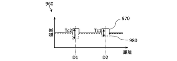
- FIG. 9B is a temperature vs. distance graph 960 provided by the arrangement of FIG. 9A according to some embodiments.
- Graph 960 shows a situation where the opening 940 is dry.
- Graph 960 includes a plot 970 for temperatures measured during the day and a plot 980 for temperatures measured at night. Both plots 970 and 980 show that the portion of fiber optic 920 embedded in the ground 910 maintains a substantially uniform temperature during both daytime and nighttime.
- graph 960 includes a second temperature change Tc2 that is greater than the first temperature change Tc1 at distance D1 and the second temperature change Tc2 has a portion of the optical fiber 920 due to a maintenance hatch. Indicates that it is not protected.
- the second temperature change Tc2 at the distance D1 is outside the temperature change threshold range. Therefore, graph 960 shows that the maintenance hatch at distance D1 has been removed. Similar to graph 860, graph 960 has a first temperature change Tc1 at distance D2. Therefore, graph 960 shows that the maintenance hatch at distance D2 remains above the optical fiber 920. Graph 960 shows that the maintenance hatch at the distance D1 is in the abnormal state and the maintenance hatch at the distance D2 is in the normal state.
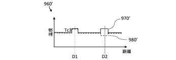
- FIG. 9C is a temperature vs. distance graph 960'provided by the arrangement of FIG. 9A according to some embodiments.
- Graph 960' shows a situation in which the portion of the optical fiber 920 in the opening 940 is covered with water.
- Both Plot 970'and Plot 980 show that the portion of fiber optic 920 embedded in the ground 910 maintains a substantially uniform temperature during both daytime and nighttime.
- the third temperature change Tc3 at the distance D1 is outside the temperature change threshold range. Therefore, graph 960'shows that the maintenance hatch at distance D1 has been removed. Similar to graph 860, graph 960'has a first temperature change Tc1 at distance D2. Therefore, graph 960'shows that the maintenance hatch at distance D2 remains above the optical fiber 920.
- FIG. 9D is a graph 960 "of temperature vs. distance provided by the arrangement of FIG. 9A according to some embodiments.
- Graph 960 shows a portion of the optical fiber 920 in the opening 940 covered with snow or ice. Shows the situation.
- Graph 960 “includes plot 970” for temperature measured during the day and plot 980 "for temperature measured at night.
- Plot 970” and plot 980 both are light embedded in the ground 910. It is shown that the portion of the fiber 920 maintains a substantially uniform temperature during both daytime and nighttime.
- graph 960 is smaller than the first temperature change Tc1 at distance D1.
- the fourth temperature change Tc4 includes the temperature change Tc4 of 4, which indicates that the portion of the optical fiber 920 is not protected by the maintenance hatch and that snow or ice covers the optical fiber 920.
- the fourth temperature change Tc4 at the distance D1 is outside the temperature change threshold range. Therefore, graph 960 "shows that the maintenance hatch at distance D1 has been removed. Similar to graph 860, graph 960" has a first temperature change Tc1 at distance D2. Therefore, graph 960 "shows that the maintenance hatch at distance D2 remains above the optical fiber 920.
- Graph 960" shows that the maintenance hatch at distance D1 is in an abnormal state and the maintenance hatch at distance D2 is in a normal state. Indicates that there is.
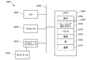
- FIG. 10 is a block diagram of the system 1000 for determining whether maintenance hatches according to some embodiments have been removed.
- the monitoring device 111 FIG. 1
- the data analysis device 260
- the system 1000 includes a hardware processor 1002 and a computer program code (program) 1006, i.e., a non-temporary computer-readable recording medium 1004 encoded with a set of executable instructions, i.e., storing the set. include.
- the computer program code 1006 is shown as an "instruction" in FIG.
- the computer-readable recording medium 1004 is shown as "memory" in FIG. Further, the computer-readable recording medium 1004 is encoded by the instruction 1007 for interfacing with an external device.
- Processor 1002 is electrically coupled to a computer-readable recording medium 1004 via bus 1008. Also, the processor 1002 is electrically coupled to the I / O interface 1010 by bus 1008. The I / O interface 1010 is shown as "I / O" in FIG.
- the network interface 1012 is also electrically connected to the processor 1002 via the bus 1008. The network interface 1012 is connected to the network 1014, whereby the processor 1002 and the computer-readable recording medium 1004 can be connected to external elements via the network 1014.
- Processor 1002 uses computer program code 1006 encoded on a computer-readable recording medium 1004 to make system 100 available for performing some or all of the steps as described in Method 300. It is configured to run.
- the processor 1002 is a central processing unit (CPU), a multiprocessor, a distributed processing system (DPS), an application specific integrated circuit (ASIC), and / or a suitable processing unit.
- CPU central processing unit
- DPS distributed processing system
- ASIC application specific integrated circuit
- the computer-readable recording medium 1004 is an electronic, magnetic, optical, electromagnetic, infrared, and / or semiconductor system (or device or device).
- the computer-readable recording medium 1004 includes a semiconductor or solid-state memory, a magnetic tape, a removable computer disk (floppy disk), a random access memory (RAM), a read-only memory (ROM), and a rigid magnetic disk. ) And / or include optical discs.
- the computer-readable recording medium 1004 includes a compact disc read-only memory (CD-ROM), a compact disc read / write (CD-R / W (CD-RW)), and a compact disc read / write (CD-RW).
- CD-ROM compact disc read-only memory
- CD-R / W compact disc read / write
- CD-RW compact disc read / write
- DVD digital video disc
- the recording medium 1004 stores computer program code 1006 that is configured to cause system 1000 to perform method 300.
- the recording medium 1004 provides information necessary to perform method 300, as well as trained model parameters 1016, pulse parameters 1018, vibration parameters 1020, sound parameters 1022, temperature parameters 1024, and / or. Also stores information generated during execution of method 300, such as a set of executable instructions for performing the steps of method 300.
- the recording medium 1004 stores instruction 1007 for interfacing with an external device.
- Instruction 1007 allows processor 1002 to generate instructions readable by an external device in order to effectively implement method 300.
- the I / O interface 1010 is coupled to an external circuit.
- the I / O interface 1010 includes a keyboard, keypad, mouse, trackball, trackpad, and / or cursor arrow keys for communicating information and commands to processor 1002.
- the system 1000 also includes a network interface 1012 coupled to the processor 1002.
- the network interface 1012 allows the system 100 to communicate with the network 1014 to which one or more other computer systems are connected.
- the network interface 1012 includes a wireless network interface such as BLUETOOTH, WIFI, WIMAX, GPRS, or WCDMA, or a wired network interface such as ETHERNET, USB, IEEE-1394.
- method 300 is implemented in two or more systems 1000, and information such as sensor data is exchanged between different systems 1000 via network 1014.
- System 1000 is configured to receive information related to the trained model via I / O interface 1010 or network interface 1012.
- the trained model is transferred to processor 1002 via bus 1008 and then stored on a computer-readable recording medium 1004 as trained model parameter 1016.
- the system 100 is configured to receive information related to pulse information via the I / O interface 1010 or network interface 1012.
- processor 1002 is configured to store information as pulse parameter 1018 on a computer-readable recording medium 1004.
- the pulse parameter 1018 is shown as a "pulse" in FIG.
- the system 1000 is configured to receive vibration-related information detected via the I / O interface 1010 or network interface 1012.
- processor 1002 is configured to generate vibration-related information based on backscattered light data received from a sensor, eg, sensor 112 (FIG. 1) or sensor 250 (FIG. 2). Has been done.
- the vibration information is stored in the computer-readable recording medium 1004 as the vibration parameter 1020.
- the vibration parameter 1020 is shown as "vibration" in FIG.
- the system 1000 is configured to receive sound-related information detected via the I / O interface 1010 or the network interface 1012.
- processor 1002 is configured to generate sound-related information based on backscattered light data received from a sensor, eg, sensor 112 (FIG. 1) or sensor 250 (FIG. 2). Has been done.
- the sound information is stored in a computer-readable recording medium 1004 as sound parameter 1022.
- the sound parameter 1022 is shown as "sound" in FIG.
- the system 1000 is configured to receive temperature-related information detected via the I / O interface 1010 or network interface 1012.
- processor 1002 is configured to generate temperature-related information based on backscattered light data received from a sensor, eg, sensor 112 (FIG. 1) or sensor 250 (FIG. 2). Has been done.
- the temperature information is stored in a computer-readable recording medium 1004 as a temperature parameter 1024.
- the temperature parameter 1024 is shown as "temperature” in FIG.
- a method of detecting the removal of a maintenance hatch is the step of transmitting an optical pulse along the optical fiber, using a step and a sensor in which the first portion of the optical fiber is in close proximity to the maintenance hatch.
- a method comprising the step of identifying whether the maintenance hatch has been removed based on the determined information.
- the method further comprises determining the distance of the first portion from the sensor based on the detected backscattered light.
- the step of determining the information includes determining whether the vibration frequency of the first portion has a peak at a selected frequency.
- the method further comprises the step of determining the selected frequency based on the material of the maintenance hatch.
- the step of determining the information includes determining the intensity of sound waves incident on the first portion of the optical fiber.
- the step of determining the information includes the step of determining the temperature of the first portion of the optical fiber.
- the method further determines the timing of removal of the maintenance hatch in response to the determined information indicating that the first portion of the optical fiber is in an abnormal state. include.
- the method further includes a step of warning the user that the maintenance hatch has been removed in response to the determined information indicating that the first portion of the optical fiber is in an abnormal state.
- the step of alerting the user includes displaying an image of a region containing the position of the first portion of the optical fiber.
- the method further comprises reporting the normal state to the user in response to the determined information indicating that the first portion of the optical fiber is in a normal state.
- the method comprises the location of the first portion of the optical fiber in response to the determined information indicating that the first portion of the optical fiber is in an abnormal state. It further includes a step of inspecting the area and a step of reporting a false positive in response to the determination that the maintenance hatch is in close proximity to the first portion of the optical fiber.
- the method is a step of determining second information relating to a second portion of the optical fiber based on the detected backscattered light, the first of the optical fibers. It further includes a step in which the second portion is in close proximity to the second maintenance hatch and a step of identifying whether the second maintenance hatch has been removed based on the determined second information.
- the system that detects the removal of the maintenance hatch is a computer-readable recording medium that is configured to store instructions and a sensor that is configured to detect backscattered light data from the fiber optics.
- a processor connected to a sensor and a computer-readable recording medium in which a first portion of the optical fiber is in close proximity to the maintenance hatch to capture the detected backscattered light data.
- the detected backscattered light data is compared with the trained model to determine information related to the first portion of the optical fiber, and the maintenance hatch is based on the determined information.
- It comprises a processor, which is configured to execute the instruction to identify whether it has been removed.
- the processor is configured to execute the instruction to determine the distance of the first portion from the sensor based on the detected backscattered light data.
- the processor is configured to execute the instruction to determine the information by determining whether the vibration frequency of the first portion has a peak at a selected frequency. Has been done.
- the processor is configured to execute the instruction to determine the selected frequency based on the material of the maintenance hatch.
- the processor is configured to execute the instructions for determining the information by determining the intensity of sound waves incident on the first portion of the optical fiber.
- the processor is configured to execute the instructions for determining the information by determining the temperature of the first portion of the optical fiber.
- the processor executes the instruction to determine the timing of removal of the maintenance hatch in response to the comparison indicating that the first portion of the optical fiber is in an abnormal state. It is configured to do.
- a computer-readable recording medium is a computer-readable recording medium that is configured to store instructions (programs) that, when executed by the processor, provide the processor with a maintenance hatch.
- the backscattered light data is received based on the backscattered light detected from the optical fiber having the first portion in close proximity, and the received backscattered light data is compared with the trained model of the optical fiber.
- the information related to the first part is determined, and based on the determined information, it is determined whether or not the maintenance hatch has been removed.
Landscapes
- Physics & Mathematics (AREA)
- General Physics & Mathematics (AREA)
- Chemical & Material Sciences (AREA)
- Analytical Chemistry (AREA)
- Business, Economics & Management (AREA)
- Emergency Management (AREA)
- Optics & Photonics (AREA)
- Measuring Temperature Or Quantity Of Heat (AREA)
Abstract
メンテナンスハッチの除去を検出する方法は、光ファイバに沿って光パルスを送信するステップを含む。前記光ファイバの第1の部分が前記メンテナンスハッチに近接している。この方法は、センサを使用して前記光ファイバからの後方散乱光を検出するステップを更に含む。この方法は、前記検出された後方散乱光とトレーニング済みモデルとの比較に基づいて前記光ファイバの前記第1の部分に関連する情報を決定するステップを更に含む。この方法は、前記決定された情報に基づいて前記メンテナンスハッチが除去されたかどうかを特定するステップを更に含む。
Description
本開示は、メンテナンスハッチの除去を特定するためのシステム及び使用方法に関する。
世界中で金属価格が高騰しているため、マンホールカバーなどのメンテナンスハッチの盗難が増大している。盗難により、メンテナンスハッチが除去されて、メンテナンスハッチの金属が販売される。幾つかの手法は、公的な報告に依存して、メンテナンスハッチが除去されたかどうかを決定する。幾つかの手法は、定期的な検査に依存して、メンテナンスハッチが除去されたかどうかを決定する。メンテナンスハッチの除去によって露出される開口の検出は、多くの場合、困難であり時間がかかる。
メンテナンスハッチの除去は、メンテナンスハッチにより覆われる公共施設(utilities)の損傷のリスクを高める。公的な報告又は定期的な検査に基づいてメンテナンスハッチの泥棒を特定することは成功の可能性が低く、これにより、メンテナンスハッチの将来の盗難のリスクが高まる。
本開示の態様は、以下の詳細な説明から、添付の図面と共に読む際に最も良く理解される。業界の標準的な慣行にしたがって、様々な特徴が原寸に比例して描かれないことに留意されたい。実際に、議論を明確にするため、様々特徴の寸法が任意に増大又は減少される場合がある。
第一の実施態様に係る方法は、メンテナンスハッチの除去を検出する方法であって、光ファイバに沿って光パルスを送信するステップであって、前記光ファイバの第1の部分が前記メンテナンスハッチに近接している、ステップと、センサを使用して前記光ファイバからの後方散乱光を検出するステップと、前記検出された後方散乱光とトレーニング済みモデルとの比較に基づいて前記光ファイバの前記第1の部分に関連する情報を決定するステップと、前記決定された情報に基づいて前記メンテナンスハッチが除去されたかどうかを特定するステップと、を含む。
第二の実施態様に係るシステムは、メンテナンスハッチの除去を検知するシステムであって、命令を記憶するように構成されているコンピュータ読み取り可能な記録媒体と、光ファイバからの後方散乱光データを検出するように構成されているセンサであって、前記光ファイバの第1の部分が前記メンテナンスハッチに近接している、センサと、前記センサと前記コンピュータ読み取り可能な記録媒体とに接続されるプロセッサであって、前記検出された後方散乱光データを受信し、前記検出された後方散乱光データとトレーニング済みモデルとの比較に基づいて前記光ファイバの前記第1の部分に関連する情報を決定し、前記決定された情報に基づいて前記メンテナンスハッチが除去されたかどうかを特定する、ための前記命令を実行するように構成されている、プロセッサと、を備える。
第三の実施態様に係るコンピュータ読み取り可能な記録媒体は、命令を記憶するように構成されているコンピュータ読み取り可能な記録媒体であって、前記命令は、プロセッサによって実行された場合に、前記プロセッサに、メンテナンスハッチに近接する第1の部分を有する光ファイバから検出された後方散乱光に基づいて後方散乱光データを受信させ、前記受信された後方散乱光データとトレーニング済みモデルとの比較に基づいて前記光ファイバの前記第1の部分に関連する情報を決定させ、前記決定された情報に基づいて前記メンテナンスハッチが除去されたかどうかを特定させる。
以下の開示は、与えられた主題の異なる特徴を実施するための多くの異なる実施形態又は例を提供する。本開示を簡略化するために、構成要素、値、工程、材料、配置などの特定の例が以下に記載される。勿論、これらは、単なる例にすぎず、限定しようとするものではない。他の構成要素、値、工程、材料、配置などが考えられる。例えば、以下の説明において第2の特徴の上方又は第2の特徴上に第1の特徴を形成することは、第1及び第2の特徴が直接に接触した状態で形成される実施形態を含んでもよいとともに、第1及び第2の特徴が直接に接触しないように更なる特徴が第1及び第2の特徴間に形成されてもよい実施形態を含んでもよい。更に、本開示は、様々な例において参照数字及び/又は文字を繰り返す場合がある。この繰り返しは、簡略及び明確のためのものであり、それ自体、論じられる様々な実施形態及び/又は形態の間の関係を定めるものではない。
マンホールカバーなどのメンテナンスハッチが除去された時期を特定することは、メンテナンスハッチの迅速な交換に役立ち、メンテナンスハッチにより覆われる公共施設のリスクを軽減する。メンテナンスハッチの除去の迅速な特定は、メンテナンスハッチが盗まれたかどうか、盗まれた場合には誰が盗んだかを特定できる可能性を高めるのにも役立つ。
本開示は、光ファイバからの後方散乱光データの測定に基づいてメンテナンスハッチが除去されたかどうかを特定するためのシステムを提供する。光ファイバは、異なる設備間の通信のために使用され、多くの場合、メンテナンスハッチ付近の位置に既に存在する。結果として、メンテナンスハッチの除去を監視するためのコストが大幅に低減される。
メンテナンスハッチの除去を特定するためのツールとしてメンテナンスハッチに近接する光ファイバを利用することは、メンテナンスハッチが除去された時期及び場所の正確で的確な決定をもたらす。地方(農村地域)の場合、メンテナンスハッチ付近を移動する人の数が少ないため、公的な報告により時宜を得た態様で紛失したメンテナンスハッチが特定されることは殆どない。結果として、下に横たわる公共施設の損傷のリスクが高まる。地方における定期的な検査も、そのような検査を行なうための移動距離が長いため、時間及び費用がかかる。本開示に記載されるシステム及び方法を使用することは、メンテナンスハッチの目視検査を必要とせずに、メンテナンスハッチの除去の低コストで正確な決定をもたらすのに役立つ。
図1は、幾つかの実施形態に係るセンサシステム(単にシステムと称する場合がある)100の概略図である。センサシステム100は、センサ112と通信する監視装置111を含む。幾つかの実施形態において、センサ112は、光パルス試験器(optical time domain reflectometer(OTDR))又は他の適したセンサを含む。センサシステム100は、センサ112に接続される光ファイバ121を更に含む。センサ112は光ファイバ121から後方散乱光を受け、後方散乱光は、その後の解析で用いる後方散乱光データと呼ばれる信号に光電的に変換される。光ファイバ121は、通信設備間で伝えられる情報に関して使用できる。光ファイバ121はメンテナンスハッチ130付近に配置される。光パルスが光ファイバ121に沿って送信される。後方散乱光は、光パルスが光ファイバ121に沿って伝播する際に生じる。センサ112は、後方散乱光を検出し、検出された後方散乱光に基づく信号を監視装置111に送信するように構成されている。
幾つかの実施形態において、メンテナンスハッチ130が歩道にある。幾つかの実施形態において、メンテナンスハッチ130が道路にある。幾つかの実施形態において、メンテナンスハッチ130が地面にある。幾つかの実施形態において、光ファイバ121がメンテナンスハッチ130によって覆われる。幾つかの実施形態において、光ファイバ121は、メンテナンスハッチ130からオフセットされるが、メンテナンスハッチ130に十分に近いため、メンテナンスハッチ130の除去に関連する振動によって影響を受ける。
光ファイバ121からの後方散乱光は、光ファイバ121の付近の環境に影響される。例えば、地面の振動は、光パルスによって生成される後方散乱光に影響を与える。振動は、歩行者が光ファイバ121の近くを歩くことにより、車両が光ファイバ121の近くを通過することにより、並びに、光ファイバ121の近くのメンテナンスハッチの除去により生じる。光ファイバ121に入射する音波も、光パルスの伝搬中に生成される後方散乱光に影響を与える。光ファイバ121の温度も後方散乱光に影響を与える。監視装置111は、後方散乱光を検出してトレーニング済み(学習済み)解析モデルを適用することにより、光ファイバ121を取り巻く環境の異常を検出することもできる。
光パルスの使用により、光ファイバ121に沿うどのポイントで異常が生じたかを決定するための後方散乱光の解析を支援される。光ファイバに沿って移動する光パルスの速度と検出された後方散乱光のタイミングとに基づき、光の後方散乱前に光パルスが移動した距離を決定できる。これは、監視装置111が異常の位置及び異常のタイミングの両方を決定するのに役立つ。
図2は、幾つかの実施形態に係るメンテナンスハッチの除去を監視するためのシステム200の概略図である。システム200は、第1の通信設備210及び第2の通信設備220を含む。光ファイバ230が第1の通信設備210を第2の通信設備220と接続する。メンテナンスハッチ240が光ファイバ230に近接して配置される。幾つかの実施形態において、光ファイバ230がメンテナンスハッチ240によって覆われる。幾つかの実施形態において、光ファイバ230がメンテナンスハッチ240からオフセットされる。センサ250が光ファイバ230に接続される。センサ250は、光ファイバ230から後方散乱光データを受信するように構成されている。データ解析デバイス260がセンサ250と通信している。監視デバイス270がデータ解析デバイス260と通信している。
光ファイバ230は、第1の通信設備210と第2の通信設備220との間で情報信号を伝えるように構成されている。幾つかの実施形態において、光ファイバ230がマルチモード光ファイバである。幾つかの実施形態において、光ファイバ230がシングルモード光ファイバである。幾つかの実施形態において、光ファイバ230が少なくとも部分的に地面に埋め込まれる。幾つかの実施形態において、光ファイバ230が導管内にある。幾つかの実施形態において、光ファイバ230が下水管内又は他の公共施設通路内にある。
メンテナンスハッチ240は、公共施設へのアクセスポイントを覆う。幾つかの実施形態において、メンテナンスハッチ240がマンホールカバーを含む。幾つかの実施形態において、メンテナンスハッチ240は、格子、掃除穴カバー(cleanout cover)、排水カバー、又は、公共施設に適した他のカバーを含む。メンテナンスハッチ240は、メンテナンスハッチ240の除去が光ファイバ230付近の周囲環境に影響を与えるように十分に光ファイバ230に近接している。幾つかの実施形態において、光ファイバ230付近の周囲環境は、メンテナンスハッチ240を除去することによってもたらされる振動に影響される。幾つかの実施形態において、光ファイバ230付近の周囲環境は、光ファイバ230に入射する音波の能力を変えることに影響される。幾つかの実施形態において、光ファイバ230付近の周囲環境は、光ファイバ230においてより大きな温度変動を可能にすることに影響される。幾つかの実施形態において、光ファイバ230付近の周囲環境は、水分が光ファイバ230と接触できるようにすることに影響される。図2は、簡単にするために、単一のメンテナンスハッチ240を含む。幾つかの実施形態において、システムが複数のメンテナンスハッチ240を含む。
センサ250は、メンテナンスハッチ240の有無に関連する光ファイバ付近の周囲環境の変化に関連付けられる後方散乱光データを含む、後方散乱光データを光ファイバ230から受信するように構成されている。センサ250は、第1の通信設備210から第2の通信設備220へ伝播する光に関する後方散乱光データを検出するように構成されている。幾つかの実施形態において、センサは、第2の通信設備220から第1の通信設備210へ伝播する光に関する後方散乱光データを検出するように構成されている。幾つかの実施形態において、システム200は、第2の通信設備220から第1の通信設備210へ伝播する光に関する後方散乱光データを受信するように構成されている第2のセンサ(図示せず)を含む。幾つかの実施形態において、センサ250がOTDR又は他の適したセンサを含む。幾つかの実施形態において、センサ250が第1の通信設備210内に収容される。幾つかの実施形態において、センサ250が第1の通信設備210とは別個のものである。幾つかの実施形態において、センサ250が第2の通信設備220内に収容される。幾つかの実施形態において、センサ250がセンサ112(図1)と同様である。
データ解析デバイス260は、センサ250から後方散乱光データを受信するように構成されている。データ解析デバイス260は、データ解析デバイス260の機能を実行するためのプロセッサを少なくとも含む。データ解析デバイス260は、後方散乱光データを解析して後方散乱光データが何らかの異常を示すかどうかを決定するように構成されている。データ解析デバイス260は、無線ネットワークによってセンサ250と通信している。幾つかの実施形態において、有線接続がデータ解析デバイス260とセンサ250との間に存在する。複数のセンサを含む幾つかの実施形態において、データ解析デバイス260は、全てのセンサから後方散乱光データを受信するように構成されている。複数のセンサを含む幾つかの実施形態において、データ解析デバイス260は、全てより少ないセンサから後方散乱光データを受信するように構成されている。幾つかの実施形態において、データ解析デバイス260は監視装置111(図1)と同様である。
データ解析デバイス260は、後方散乱光データを解析するためにトレーニング済みモデル(学習済みモデル)を使用する。幾つかの実施形態において、トレーニング済みモデルは、外部デバイスによってデータ解析デバイス260に与えられる。幾つかの実施形態において、トレーニング済みモデルは、データ解析デバイス260によって構築される。
トレーニング済みモデルは、教師データ(teaching data)を使用して構築される。教師データは、後方散乱光データの正常状態及び異常状態に関する情報を含む。正常状態は、メンテナンスハッチ240が適切に位置されるときの光ファイバ230の状態を示すサンプルの後方散乱光データを含む。異常状態は、メンテナンスハッチ240が除去されるときの光ファイバ230の状態を示すサンプル後方散乱光データを含む。幾つかの実施形態において、光ファイバ230の状態は、光ファイバ230の振動、光ファイバ230に入射する音波、又は、光ファイバ230の温度変動のうちの少なくとも1つに関連付けられる。幾つかの実施形態において、教師データが、予測データ又はコンピュータ生成データを含む。幾つかの実施形態において、教師データは、経験的データを含む。幾つかの実施形態において、教師データは、予測データ又はコンピュータ生成データと経験的データとの組み合わせを含む。
データ解析デバイス260は、センサ250から受信される実際のデータをトレーニング済みモデルと比較して、光ファイバ230の状態が正常か又は異常かを決定する。幾つかの実施形態において、データ解析デバイス260は、光ファイバ230の異常状態を決定するのを支援するために外部デバイスから気象データを受信するように構成されている。幾つかの実施形態において、比較結果が監視デバイス270に転送される。
監視デバイス270は、データ解析デバイス260による解析結果を受信して、その結果をユーザに提供するように構成されている。監視デバイス270は、少なくともディスプレイ及びプロセッサを含む。幾つかの実施形態において、監視デバイス270は、データ解析デバイス260と無線通信する。幾つかの実施形態において、監視デバイス270は、データ解析デバイス260に対する有線接続を有する。
監視デバイス270は、光ファイバ230の異常状態を示すデータ解析デバイス260からの解析(解析結果)に応じて警告を表示する。幾つかの実施形態において、警告は、テキスト、音声、又は、図形(画像)データを含む。幾つかの実施形態において、警告は、光ファイバ230の異常状態の位置に関連する情報を含む。幾つかの実施形態において、警告は、光ファイバ230の異常状態の開始のタイミングを含む。幾つかの実施形態において、監視デバイス270は、光ファイバ230の正常状態を示すデータ解析デバイス260からの解析(解析結果)に応じて正常状態を表示する。
幾つかの実施形態において、監視デバイス270は、メンテナンスハッチ240を含む領域の画像を撮るための少なくとも1つのローカル(現地)の撮像デバイスに接続される。幾つかの実施形態において、監視デバイス270は、メンテナンスハッチ240の位置における光ファイバ230の異常状態を示すデータを受信することに応じてメンテナンスハッチ240と関連付けられているローカルの撮像デバイスからの画像を表示する。幾つかの実施形態において、監視デバイス270は、ユーザに表示するために光ファイバ230の異常状態の決定された開始タイミングに基づいてローカルの撮像デバイスから受け取った画像を選択する。
幾つかの実施形態において、監視デバイス270が省略される。幾つかの実施形態において、比較結果は、光ファイバ230の異常状態の決定に応じてユーザに送られる。幾つかの実施形態において、警告は、ユーザによりアクセス可能なモバイルデバイスに送られる。幾つかの実施形態において、警告は、テキスト、音声、又は、図形(画像)データを含む。
光ファイバ230の異常状態のタイミング及び位置を正確に且つ即座に検出できる能力により、システム200は、メンテナンスハッチ240が除去されたかどうかを迅速に決定することができる。これにより、メンテナンスハッチ240の迅速な交換が容易になり、公共施設の損傷のリスクが軽減される。更に、光ファイバ230の検出された異常状態とメンテナンスハッチ240の撮像とを組み合わせることは、メンテナンスハッチ240の盗難を特定できる能力を高め、それにより、泥棒の捕獲及び将来の盗難の抑止につながり得る。光ファイバ230の検出された異常状態とメンテナンスハッチ240の撮像とを組み合わせることは、異常検出データにおける誤判定(誤った決定)(false positive)を特定するのにも役立つ。これらの誤判定は、トレーニング済みモデルの精度を向上させるためにデータ解析デバイス260によって使用されるトレーニング済みモデルにフィードバックすることができる。監視デバイス270を含まない幾つかの実施形態においても、光ファイバ230の異常状態の表示に続くメンテナンスハッチ240の検査が、メンテナンスハッチ240が所定位置に留まっていることを示す場合、その情報をトレーニング済みモデルへフィードバックすることができる。
幾つかの実施形態において、データ解析デバイス260又は監視デバイス270は、スケジューリングされたメンテナンスを、光ファイバ230の検出された異常状態と相互参照することができる。スケジューリングされたメンテナンスを光ファイバ230の検出された異常状態と相互参照することにより、メンテナンスハッチ240の除去に関するユーザへの不必要な警告が減少又は回避される。
図3は、幾つかの実施形態に係るメンテナンスハッチの除去を特定する方法300のフローチャートである。工程305では、光ファイバ、例えば、光ファイバ121(図1)又は光ファイバ230(図2)に沿って光パルスが送信される。幾つかの実施形態において、光ファイバがマルチモード光ファイバを備える。幾つかの実施形態において、光ファイバがシングルモード光ファイバを備える。幾つかの実施形態において、光ファイバがメンテナンスハッチによって覆われる。幾つかの実施形態において、光ファイバがメンテナンスハッチからオフセットされる。光ファイバがメンテナンスハッチに十分に近接しているので、メンテナンスハッチが除去されると光ファイバの一部分の付近の周囲環境に影響が与えられる。
工程310では、後方散乱光データが光ファイバから検出される。後方散乱光データは、光ファイバ内の反射、例えばレイリー(Rayleigh)反射の結果である。光ファイバ付近の状態が変化すると、後方散乱光データの違いを検出できる。幾つかの実施形態において、後方散乱光データがOTDRを使用して検出される。幾つかの実施形態において、後方散乱光データがセンサ112(図1)又はセンサ250(図2)を使用して検出される。
工程315において、後方散乱光データが解析されることにより、光ファイバの付近に異常状態が存在するかどうかが決定される。幾つかの実施形態において、異常状態は、光ファイバの振動、光ファイバに入射する音波、又は、光ファイバの温度変動のうちの少なくとも1つに起因して検出可能である。後方散乱光データは、後方散乱光データとトレーニング済みモデルとの比較を使用して解析される。幾つかの実施形態において、後方散乱光データが監視装置111(図1)を使用して解析される。幾つかの実施形態において、後方散乱光データがデータ解析デバイス260(図2)を使用して解析される。
異常状態が検出されないとの決定に応じて、幾つかの実施形態において、方法300が任意の工程320に進む。任意の工程320では、正常状態であることがユーザに報告される。幾つかの実施形態において、正常状態であることが、監視端末、例えば、監視デバイス270によってユーザに報告される。幾つかの実施形態において、正常状態であることは、ユーザによりアクセス可能なモバイルデバイスを使用してユーザに報告される。幾つかの実施形態において、正常状態であることは、テキスト、音声、又は、図形(画像)情報を使用して報告される。
幾つかの実施形態において、任意の工程320が省かれる。任意の工程320は、ユーザが主にメンテナンスハッチの除去を特定することに携わっている状況において省かれる。任意の工程320が省かれる場合には、正常状態がユーザに報告されない。
異常状態が検出されたとの決定に応じて、方法300が工程325に進む。工程325では、光ファイバに沿った異常状態の位置が決定される。光ファイバに沿った異常状態の位置は、工程305からの対応する送信パルスに関して検出された後方散乱光データのタイミングに基づく。異常状態の位置を決定することにより、異常状態の原因と推定されるメンテナンスハッチの位置が特定される。異常状態の位置は、プロセッサを使用して決定される。幾つかの実施形態において、異常状態の位置が監視装置111(図1)によって決定される。幾つかの実施形態において、異常状態の位置がセンサ250によって決定される(図2)。異常状態の位置を検出することにより、メンテナンスハッチを迅速に交換して、下に横たわる公共施設の損傷のリスクを減らすことができる。
任意の工程330では、光ファイバに沿った異常状態の開始のタイミングが決定される。光ファイバに沿った異常状態の開始のタイミングは、検出された後方散乱光データがいつ受信されたかに基づく。異常状態の開始のタイミングを決定することにより、メンテナンスハッチが除去された時刻が特定される。異常状態の開始のタイミングは、プロセッサを使用して決定される。幾つかの実施形態において、異常状態の開始のタイミングが監視装置111(図1)によって決定される。幾つかの実施形態において、異常状態の開始のタイミングがセンサ250によって決定される(図2)。異常状態の開始のタイミングを検出することにより、潜在的な泥棒を特定する機会が増える。
幾つかの実施形態において、任意の工程330が省略される。異常状態の性質が異常状態の開始と異常状態の検出との間にかなりの遅延を引き起こす状況では、任意の工程330が省略される。例えば、気象の変動に基づいて異常状態が検出される場合には、異常状態の検出が大幅に遅れる可能性がある。これは、異常状態の検出が、場合によっては、メンテナンスハッチの除去後数時間にわたって生じない温度差(又は予期される温度差)に基づくからである。他の例では、地方(農村地域)で光ファイバに入射する音波に基づいて異常状態が検出される場合、メンテナンスハッチが最初に除去された後にかなりの時間が経ってから、音波源が除去されたメンテナンスハッチを通過する可能性が高い。任意の工程330の省略は、異常状態の開始のタイミングが有用な情報となり得る可能性が低い場合において解析のための処理負荷の軽減に役立つ。
工程335では、異常状態の警告がユーザに伝達される。幾つかの実施形態において、警告は、異常状態の位置及び/又はタイミングに関する情報を含む。幾つかの実施形態において、警告は、テキスト、音声、又は、図形(画像)データを含む。幾つかの実施形態において、警告は、検出された異常状態に関連するメンテナンスハッチを含む領域の画像と組み合わされる。幾つかの実施形態において、警告は監視デバイス270(図2)を使用して伝達される。幾つかの実施形態において、警告はユーザによりアクセス可能なモバイルデバイスに伝達される。幾つかの実施形態において、警告は、メンテナンスハッチの除去に対する不必要な懸念を軽減又は回避するためにメンテナンスハッチと関連付けられたスケジューリングされたメンテナンスに関連する情報と共に伝達される。
幾つかの実施形態において、更なる工程が方法300に含まれる。例えば、幾つかの実施形態において、誤判定が、トレーニング済みモデルの精度を向上させるためにトレーニング済みモデルにフィードバックされる。幾つかの実施形態において、少なくとも1つの工程が省略される。例えば、幾つかの実施形態において、任意の工程330が前述したように省略される。幾つかの実施形態において、方法300の工程の順序が変更される。例えば、幾つかの実施形態において、任意の工程320は、異常状態が検出されるまで正常状態が報告されるように工程315の前に実行される。
方法300は、光ファイバの異常状態のタイミング及び/又は位置を正確に且つ迅速に検出できる能力を高めるのに役立つ。これにより、メンテナンスハッチの迅速な交換が容易になり、公共施設の損傷のリスクが軽減される。
図4は、幾つかの実施形態に係る検出された後方散乱光データのグラフ400である。グラフ400は、光ファイバからの後方散乱光データに関する経時的な特定の検出された周波数での振幅を含む。グラフ400は、グラフ400の他の部分と比較して、約15秒~約60秒の時間範囲で検出された周波数の振幅が増大していることを含む。このタイプのデータは、例えば、光ファイバを取り巻く周囲環境における振動の発生を決定するために使用できる。
図5Aは、幾つかの実施形態に係る検出された後方散乱光データに基づく周波数対振幅のグラフ500である。幾つかの実施形態において、グラフ500は、後方散乱光データにおいて収集された情報に対してフーリエ変換を用いることにより生成される。グラフ500はプロット510を含む。プロット510における小さい変化は、異なる周波数における小さい振動変化を示す。第1の周波数F1は、車両が光ファイバの振動をもたらす可能性が高い周波数である。幾つかの実施形態において、第1の周波数F1が約50ヘルツ(Hz)にある。第2の周波数F2は、メンテナンスハッチの除去が光ファイバの振動をもたらす可能性が高い周波数である。幾つかの実施形態において、第2の周波数F2が約70Hzにある。幾つかの実施形態において、異なるメンテナンスハッチの除去が異なる周波数の生成をもたらす。メンテナンスハッチの除去によって生成される周波数は、メンテナンスハッチの材料、開口におけるメンテナンスハッチの取り付けのタイプ、メンテナンスハッチのサイズ、及び、メンテナンスハッチの形状によって決まる。トレーニング済みモデルを光ファイバに沿った異なる複数の位置におけるメンテナンスハッチのタイプに関連する情報と組み合わせて使用することにより、メンテナンスハッチの除去の検出の正確性が向上される。プロット510は、第1の周波数F1又は第2の周波数F2のいずれかにおいも顕著なピークを含まない。これは正常状態を示す。幾つかの実施形態において、プロット510などのプロットの生成に応じて、監視装置111(図1)又はデータ解析デバイス260(図2)は、光ファイバが正常状態にあると決定する。
図5Bは、幾つかの実施形態に係る検出された後方散乱光データに基づく周波数対振幅のグラフ500’である。幾つかの実施形態において、グラフ500’は、後方散乱光データで収集された情報に対してフーリエ変換を使用することにより生成される。グラフ500’はプロット510’を含む。プロット510(図5A)と比較して、プロット510’は第1の周波数F1でピークを含む。第1の周波数F1におけるピークは、車両の通過を示す。第1の周波数におけるピークは、メンテナンスハッチの除去を示してはいない。したがって、プロット510’は正常状態を示しているであろう。幾つかの実施形態において、プロット510’などのプロットの生成に応じて、監視装置111(図1)又はデータ解析デバイス260(図2)は、光ファイバが正常状態にあると決定する。
図5Cは、幾つかの実施形態に係る検出された後方散乱光データに基づく周波数対振幅のグラフ500”である。幾つかの実施形態において、グラフ500”は、後方散乱光データで収集された情報に対してフーリエ変換を使用することにより生成される。グラフ500”はプロット510”を含む。プロット510(図5A)と比較して、プロット510”は第2の周波数F2でピークを含む。第2の周波数F2におけるピークは、メンテナンスハッチの除去を示す。したがって、プロット510”は異常状態を示しているであろう。幾つかの実施形態において、プロット510”などのプロットの生成に応じて、監視装置111(図1)又はデータ解析デバイス260(図2)は、光ファイバが異常状態にあると決定する。
グラフ400(図4)などのタイミング後方散乱光データをプロット510”(図5C)などの異常状態検出と組み合わせることにより、メンテナンスハッチの除去のタイミング及び位置の両方を決定できる。この情報の組み合わせは、除去されたメンテナンスハッチの交換のための迅速な対応と、メンテナンスハッチの盗難を特定する機会の増大とに役立つ。
図6Aは、幾つかの実施形態に係る光ファイバ620の上方の開口640を覆うメンテナンスハッチ630の配置600の図である。配置600は、地面610の開口640を覆うメンテナンスハッチ630を含む。幾つかの実施形態において、開口640は下水管又は他の公共施設導管にある。光ファイバ620は、メンテナンスハッチ630の下方にあり、メンテナンスハッチ630によってメンテナンスハッチ630の反対側にある環境から保護される。メンテナンスハッチの反対側の環境からの音波650は、音源(図示せず)によって生成される。メンテナンスハッチ630は、配置600から分かるように、音波650のかなりの部分を反射又は変向する。結果として、わずかな量の音波650が光ファイバ620に入射する(又は全く入射しない)。
図6Bは、幾つかの実施形態に係る図6Aの配置によりもたらされた強度対距離のグラフ660である。グラフ660はプロット670を含む。プロット670は、光ファイバ620に沿って入射する音波の強度の僅かな変化を示す。光ファイバ620に沿った音波の強度の変化は全て、強度閾値Ithを下回る。光ファイバ620に入射する音波の強度は、光ファイバ620の深さ、開口640のサイズ、地面610の材料、及び、開口640の形状及び向きによって決まる。幾つかの実施形態において、ユーザは、これらの因子を利用して、強度閾値Ithを設定する。幾つかの実施形態において、プロセッサ、例えば、監視装置111(図1)又はデータ解析デバイス260(図2)は、これらの因子を利用して強度閾値Ithを決定する。これは、メンテナンスハッチ630の正常状態を示す。グラフ660は、光ファイバ620に沿ったメンテナンスハッチ630の位置を示す第1の距離D1を含む。グラフ660は、光ファイバ620に沿った第2のメンテナンスハッチ(図示せず)の位置を示す第2の距離D2を更に含む。距離D1,D2は、センサ、例えば、センサ112(図1)又はセンサ250(図2)からの距離である。プロット670は、距離D1におけるメンテナンスハッチ630及び距離D2における第2のメンテナンスハッチの両方が正常状態にあることを示す。
図7Aは、幾つかの実施形態に係るメンテナンスハッチを伴わない光ファイバ720の上方の開口740の配置700の図である。配置600と比較して、配置700はメンテナンスハッチを含んでおらず、すなわち、メンテナンスハッチが地面710の開口740上から除去されている。幾つかの実施形態において、開口740が下水管又は他の公共施設導管にある。光ファイバ720は、メンテナンスハッチを配すべき位置の下方にあるが、開口740の外側の環境に晒されている。開口の外側の環境からの音波750は、開口740を通って伝播して、光ファイバ720に入射することができる。
図7Bは、幾つかの実施形態に係る図7Aの配置によりもたらされた強度対距離のグラフ760である。グラフ760はプロット770を含む。プロット670と比較して、プロット770は、音波750がメンテナンスハッチによって遮断されないことを示す強度スパイク(intensity spike)を距離D1において含む。距離D1における強度ピークは強度閾値Ithを超える。したがって、プロット770は、距離D1におけるメンテナンスハッチが除去されたことを示す。プロット670と同様に、プロット770は距離D2においてピークを含まない。したがって、プロット770は、距離D2におけるメンテナンスハッチが光ファイバ720の上方に残存することを示す。プロット770は、距離D1におけるメンテナンスハッチが異常状態にあるとともに距離D2におけるメンテナンスハッチが正常状態にあることを示す。
図8Aは、幾つかの実施形態に係るメンテナンスハッチ830によって覆われた開口840を含む埋め込まれた光ファイバ820の配置800の図である。配置800は、地面810の開口840を覆うメンテナンスハッチ830を含む。幾つかの実施形態において、開口840が下水管又は他の公共施設導管にある。光ファイバ820は、メンテナンスハッチ830の下方にあり、メンテナンスハッチ830によってメンテナンスハッチ830の反対側にある環境から保護される。地面810に埋め込まれた又は地面810に埋め込まれた導管に埋め込まれた光ファイバ820の部分は、地面810の温度が略均一であるため日中及び夜間の両方にわたって温度が略均一である。これに対し、開口840内の光ファイバ820の部分は、気温の変化により温度の変動を示す。例えば、日中の温度は、一般に、夜間の温度よりも高い。したがって、開口840内の光ファイバ820の部分は、昼から夜への温度変動を示すと予期される。メンテナンスハッチ830が開口840を覆っている場合には、熱が日中にメンテナンスハッチ830によって反射されまたメンテナンスハッチ830は夜間に開口840を断熱するため、開口840内の光ファイバ820の部分の温度変動の大きさは、光ファイバが露出している場合と比較して減少される。
図8Bは、幾つかの実施形態に係る図8Aの配置によりもたらされた温度対強度のグラフ860である。グラフ860は、日中に測定された温度に関するプロット870と、夜間に測定された温度に関するプロット880とを含む。プロット870及びプロット880はいずれも、地面810に埋め込まれた光ファイバ820の部分が日中及び夜間の両方の間にわたって略均一な温度を維持することを示す。グラフ860は、光ファイバ820に沿ったメンテナンスハッチ830の位置を示す第1の距離D1を含む。グラフ860は、光ファイバ820に沿った第2のメンテナンスハッチ(図示せず)の位置を示す第2の距離D2を更に含む。距離D1,D2は、センサ、例えば、センサ112(図1)又はセンサ250(図2)からの距離である。プロット870は、距離D1におけるメンテナンスハッチ630の下の光ファイバ820の部分及び距離D2における第2のメンテナンスハッチの下の光ファイバ820の部分の両方が日中において地面810に埋め込まれた光ファイバ820の部分よりも高い温度を有することを示す。プロット880は、距離D1におけるメンテナンスハッチ630の下の光ファイバ820の部分及び距離D2における第2のメンテナンスハッチの下の光ファイバ820の部分の両方が夜間において地面810に埋め込まれた光ファイバ820の部分よりも低い温度を有することを示す。第1の距離D1及び第2の距離D2の両方におけるプロット870とプロット880との間の温度変化は、第1の温度変化Tc1である。光ファイバ620の温度変化は、光ファイバ820の深さ、開口840のサイズ、地面810の材料、及び、開口840の形状及び向きによって決まる。幾つかの実施形態において、ユーザは、これらの因子を利用して、温度変化閾値範囲を決定し、温度変化が予期される範囲内にあるかどうかを決定する。幾つかの実施形態において、プロセッサ、例えば、監視装置111(図1)又はデータ解析デバイス260(図2)は、これらの因子を利用して、温度変化が予期される範囲内にあるかどうかを決定するための温度変化閾値範囲を決定する。幾つかの実施形態において、温度変化閾値範囲を決定するために外部デバイスからの記録された気象条件(気象状況)が使用される。すなわち、温度変化閾値範囲は、幾つかの実施形態において、メンテナンスハッチ830の位置における記録された気象条件に応じて変化する。温度変化Tc1は、メンテナンスハッチ830における正常状態を示す。
図9Aは、幾つかの実施形態に係るメンテナンスハッチを伴わない開口940を含む埋め込み光ファイバ920の配置900の図である。配置800と比較して、配置900はメンテナンスハッチを含まず、すなわち、メンテナンスハッチが地面910の開口940から除去されている。幾つかの実施形態において、開口940が下水管又は他の公共施設導管にある。光ファイバ920は、メンテナンスハッチを配すべき位置の下方にあるが、開口940の外側の環境に晒されている。開口940内の光ファイバ920の部分は、外部環境に晒されている。メンテナンスハッチによる熱の反射やメンテナンスハッチによる光ファイバ920の断熱はない。結果として、開口内の光ファイバ920の温度変動は、配置800の場合のようにメンテナンスハッチが開口940を覆っている状況とは異なる。例えば、開口940が乾燥している場合、日中から夜間への温度変化は、場合によっては、配置800と比較してより高い大きさを有する。開口940内の光ファイバ920の部分が水で覆われる場合には、周囲の地面温度に起因して水が略一定の温度を維持するため、光ファイバ920のその部分の温度変化が減少する。これは、メンテナンスハッチの除去に起因して光ファイバ920のその部分が雨に晒されていることを示している。開口940内の光ファイバ920の部分が雪又は氷で覆われる場合には、光ファイバ920のその部分の温度変化もまた雪又は氷に起因して減少する。これは、メンテナンスハッチの除去に起因して光ファイバ920のその部分が雪に晒されていることを示している。
図9Bは、幾つかの実施形態に係る図9Aの配置によりもたらされた温度対距離のグラフ960である。グラフ960は、開口940が乾燥している状況を示す。グラフ960は、日中に測定された温度に関するプロット970と、夜間に測定された温度に関するプロット980とを含む。プロット970及びプロット980はいずれも、地面910に埋め込まれた光ファイバ920の部分が日中及び夜間の両方の間にわたって略均一な温度を維持することを示す。グラフ860と比較して、グラフ960は、距離D1における第1の温度変化Tc1よりも大きい第2の温度変化Tc2を含み、この第2の温度変化Tc2は、光ファイバ920の部分がメンテナンスハッチによって保護されないことを示す。距離D1における第2の温度変化Tc2は、温度変化閾値範囲外である。したがって、グラフ960は、距離D1におけるメンテナンスハッチが除去されたことを示す。グラフ860と同様に、グラフ960は、距離D2において第1の温度変化Tc1を有する。したがって、グラフ960は、距離D2におけるメンテナンスハッチが光ファイバ920の上方に残存することを示す。グラフ960は、距離D1におけるメンテナンスハッチが異常状態にあるとともに距離D2におけるメンテナンスハッチが正常状態にあることを示す。
図9Cは、幾つかの実施形態に係る図9Aの配置によりもたらされた温度対距離のグラフ960’である。グラフ960’は、開口940内の光ファイバ920の部分が水で覆われる状況を示す。グラフ960’は、日中に測定された温度に関するプロット970’と、夜間に測定された温度に関するプロット980’とを含む。プロット970’及びプロット980はいずれも、地面910に埋め込まれた光ファイバ920の部分が日中及び夜間の両方の間にわたって略均一な温度を維持することを示す。グラフ860と比較して、グラフ960’は、距離D1における第1の温度変化Tc1よりも小さい第3の温度変化Tc3を含み、この第3の温度変化Tc3は、光ファイバ920の部分がメンテナンスハッチによって保護されないこと及び水が光ファイバ920を覆っていることを示す。開口940内の光ファイバ920の温度が光ファイバ920の埋め込まれた部分よりも高いことは、水が光ファイバ920を取り囲んでいることを示す。距離D1における第3の温度変化Tc3は、温度変化閾値範囲外である。したがって、グラフ960’は、距離D1におけるメンテナンスハッチが除去されたことを示す。グラフ860と同様に、グラフ960’は、距離D2において第1の温度変化Tc1を有する。したがって、グラフ960’は、距離D2におけるメンテナンスハッチが光ファイバ920の上方に残存することを示す。グラフ960’は、距離D1におけるメンテナンスハッチが異常状態にあるとともに距離D2におけるメンテナンスハッチが正常状態にあることを示す。
図9Dは、幾つかの実施形態に係る図9Aの配置によりもたらされた温度対距離のグラフ960”である。グラフ960”は、開口940内の光ファイバ920の部分が雪又は氷で覆われている状況を示す。グラフ960”は、日中に測定された温度に関するプロット970”と、夜間に測定された温度に関するプロット980”とを含む。プロット970”及びプロット980”はいずれも、地面910に埋め込まれた光ファイバ920の部分が日中及び夜間の両方の間にわたって略均一な温度を維持することを示す。グラフ860と比較して、グラフ960”は、距離D1における第1の温度変化Tc1よりも小さい第4の温度変化Tc4を含み、この第4の温度変化Tc4は、光ファイバ920の部分がメンテナンスハッチによって保護されないこと及び雪又は氷が光ファイバ920を覆っていることを示す。開口940内の光ファイバ920の温度が光ファイバ920の埋め込まれた部分よりも低いことは、雪又は氷が光ファイバ920を取り囲んでいることを示す。距離D1における第4の温度変化Tc4は、温度変化閾値範囲外である。したがって、グラフ960”は、距離D1におけるメンテナンスハッチが除去されたことを示す。グラフ860と同様に、グラフ960”は、距離D2において第1の温度変化Tc1を有する。したがって、グラフ960”は、距離D2におけるメンテナンスハッチが光ファイバ920の上方に残存することを示す。グラフ960”は、距離D1におけるメンテナンスハッチが異常状態にあるとともに距離D2におけるメンテナンスハッチが正常状態にあることを示す。
図10は、幾つかの実施形態にしたがったメンテナンスハッチが除去されているかどうかを決定するためのシステム1000のブロック図である。幾つかの実施形態において、監視装置111(図1)又はデータ解析デバイス(260)は、システム1000を使用して実装される。システム1000は、ハードウェアプロセッサ1002と、コンピュータプログラムコード(プログラム)1006、すなわち、実行可能命令のセットでエンコードされた、すなわち、該セットを記憶する非一時的なコンピュータ読み取り可能な記録媒体1004とを含む。
コンピュータプログラムコード1006は図10において「命令」として示す。コンピュータ読み取り可能な記録媒体1004は、図10において「メモリ」として示す。また、コンピュータ読み取り可能な記録媒体1004は、外部デバイスとインタフェースをとるための命令1007でエンコードされる。プロセッサ1002は、バス1008を介してコンピュータ読み取り可能な記録媒体1004に電気的に結合される。また、プロセッサ1002は、バス1008によってI/Oインタフェース1010に電気的に結合される。I/Oインタフェース1010は、図10において「I/O」として示す。また、ネットワークインタフェース1012もバス1008を介してプロセッサ1002に電気的に接続される。ネットワークインタフェース1012はネットワーク1014に接続され、それにより、プロセッサ1002及びコンピュータ読み取り可能な記録媒体1004はネットワーク1014を介して外部要素に接続できる。プロセッサ1002は、システム100を方法300に記載されるような工程の一部又は全部の実行のために利用できるようにするために、コンピュータ読み取り可能な記録媒体1004にエンコードされたコンピュータプログラムコード1006を実行するように構成されている。
コンピュータプログラムコード1006は図10において「命令」として示す。コンピュータ読み取り可能な記録媒体1004は、図10において「メモリ」として示す。また、コンピュータ読み取り可能な記録媒体1004は、外部デバイスとインタフェースをとるための命令1007でエンコードされる。プロセッサ1002は、バス1008を介してコンピュータ読み取り可能な記録媒体1004に電気的に結合される。また、プロセッサ1002は、バス1008によってI/Oインタフェース1010に電気的に結合される。I/Oインタフェース1010は、図10において「I/O」として示す。また、ネットワークインタフェース1012もバス1008を介してプロセッサ1002に電気的に接続される。ネットワークインタフェース1012はネットワーク1014に接続され、それにより、プロセッサ1002及びコンピュータ読み取り可能な記録媒体1004はネットワーク1014を介して外部要素に接続できる。プロセッサ1002は、システム100を方法300に記載されるような工程の一部又は全部の実行のために利用できるようにするために、コンピュータ読み取り可能な記録媒体1004にエンコードされたコンピュータプログラムコード1006を実行するように構成されている。
幾つかの実施形態において、プロセッサ1002は、中央演算処理装置(CPU)、マルチプロセッサ、分散処理システム(DPS)、特定用途向け集積回路(ASIC)、及び/又は、適切な処理ユニットである。
幾つかの実施形態において、コンピュータ読み取り可能な記録媒体1004は、電子、磁気、光学、電磁、赤外線、及び/又は、半導体システム(或いは装置又はデバイス)である。例えば、コンピュータ読み取り可能な記録媒体1004は、半導体又は固体メモリ、磁気テープ、取り外し可能なコンピュータディスク(フロッピーディスク)、ランダムアクセスメモリ(RAM)、リードオンリーメモリ(ROM)、剛性磁気ディスク(rigid magnetic disk)、及び/又は、光ディスクを含む。光ディスクを使用する幾つかの実施形態において、コンピュータ読み取り可能な記録媒体1004は、コンパクトディスクリードオンリーメモリ(CD-ROM)、コンパクトディスクリード/ライト(CD-R/W(CD-RW))、及び/又は、デジタルビデオディスク(DVD)を含む。
幾つかの実施形態において、記録媒体1004は、システム1000に方法300を実行させるように構成されているコンピュータプログラムコード1006を記憶する。幾つかの実施形態において、記録媒体1004は、方法300を実行するために必要な情報、並びに、トレーニング済みモデルパラメータ1016、パルスパラメータ1018、振動パラメータ1020、音パラメータ1022、温度パラメータ1024、及び/又は、方法300の工程を実行するための実行可能な命令のセットなどの方法300を実行する最中に生成される情報も記憶する。
幾つかの実施形態において、記録媒体1004は、外部デバイスとインタフェースをとるための命令1007を記憶する。命令1007は、方法300を効果的に実施するために、プロセッサ1002が外部デバイスによって読み取り可能な命令を生成できるようにする。
システム1000はI/Oインタフェース1010を含む。I/Oインタフェース1010は外部回路に結合される。幾つかの実施形態において、I/Oインタフェース1010は、情報及びコマンドをプロセッサ1002に通信するためのキーボード、キーパッド、マウス、トラックボール、トラックパッド、及び/又は、カーソル方向キーを含む。
また、システム1000は、プロセッサ1002に結合されるネットワークインタフェース1012も含む。ネットワークインタフェース1012は、1つ以上の他のコンピュータシステムが接続されるネットワーク1014とシステム100が通信できるようにする。ネットワークインタフェース1012は、BLUETOOTH、WIFI、WIMAX、GPRS、又は、WCDMAなどの無線ネットワークインタフェース、或いは、ETHERNET、USB、IEEE-1394などの有線ネットワークインタフェースを含む。幾つかの実施形態において、方法300が2つ以上のシステム1000で実施され、また、センサデータなどの情報がネットワーク1014を介して異なる複数のシステム1000間でやりとりされる。
システム1000は、I/Oインタフェース1010又はネットワークインタフェース1012を介してトレーニング済みモデルに関連する情報を受信するように構成されている。トレーニング済みモデルは、バス1008を介してプロセッサ1002に転送され、その後、トレーニング済みモデルパラメータ1016としてコンピュータ読み取り可能な記録媒体1004に記憶される。幾つかの実施形態において、システム100は、I/Oインタフェース1010又はネットワークインタフェース1012を介してパルス情報に関連する情報を受信するように構成されている。幾つかの実施形態において、プロセッサ1002は、情報をパルスパラメータ1018としてコンピュータ読み取り可能な記録媒体1004に記憶するように構成されている。パルスパラメータ1018は、図10において「パルス」として示す。幾つかの実施形態において、システム1000は、I/Oインタフェース1010又はネットワークインタフェース1012を介して検出された振動に関連する情報を受信するように構成されている。幾つかの実施形態において、プロセッサ1002は、センサ、例えば、センサ112(図1)又はセンサ250(図2)から受信される後方散乱光データに基づいて振動に関連する情報を生成するように構成されている。振動情報は、振動パラメータ1020としてコンピュータ読み取り可能な記録媒体1004に記憶される。振動パラメータ1020は、図10において「振動」として示す。幾つかの実施形態において、システム1000は、I/Oインタフェース1010又はネットワークインタフェース1012を介して検出された音に関連する情報を受信するように構成されている。幾つかの実施形態において、プロセッサ1002は、センサ、例えば、センサ112(図1)又はセンサ250(図2)から受信される後方散乱光データに基づいて音に関連する情報を生成するように構成されている。音情報は、音パラメータ1022としてコンピュータ読み取り可能な記録媒体1004に記憶される。音パラメータ1022は、図10において「音」として示す。幾つかの実施形態において、システム1000は、I/Oインタフェース1010又はネットワークインタフェース1012を介して検出された温度に関連する情報を受信するように構成されている。幾つかの実施形態において、プロセッサ1002は、センサ、例えば、センサ112(図1)又はセンサ250(図2)から受信される後方散乱光データに基づいて温度に関連する情報を生成するように構成されている。温度情報は、温度パラメータ1024としてコンピュータ読み取り可能な記録媒体1004に記憶される。温度パラメータ1024は、図10において「温度」として示す。
(付記1)
メンテナンスハッチの除去を検出する方法は、光ファイバに沿って光パルスを送信するステップであって、前記光ファイバの第1の部分が前記メンテナンスハッチに近接している、ステップと、センサを使用して前記光ファイバからの後方散乱光を検出するステップと、前記検出された後方散乱光とトレーニング済みモデルとの比較に基づいて前記光ファイバの前記第1の部分に関連する情報を決定するステップと、前記決定された情報に基づいて前記メンテナンスハッチが除去されたかどうかを特定するステップと、を含む方法。
(付記2)
幾つかの実施形態において、前記方法は、前記検出された後方散乱光に基づいて前記センサからの前記第1の部分の距離を決定するステップを更に含む。
(付記3)
幾つかの実施形態において、前記情報を決定するステップは、前記第1の部分の振動周波数が選択された周波数でピークを有するかどうかを決定するステップを含む。
(付記4)
幾つかの実施形態において、前記方法は、前記メンテナンスハッチの材料に基づいて前記選択された周波数を決定するステップを更に含む。
(付記5)
幾つかの実施形態において、前記情報を決定するステップは、前記光ファイバの前記第1の部分に入射する音波の強度を決定するステップを含む。
(付記6)
幾つかの実施形態において、前記情報を決定するステップは、前記光ファイバの前記第1の部分の温度を決定するステップを含む。
(付記7)
幾つかの実施形態において、前記方法は、前記光ファイバの前記第1の部分が異常状態にあることを示す前記決定された情報に応じて、前記メンテナンスハッチの除去のタイミングを決定するステップを更に含む。
(付記8)
前記方法は、前記光ファイバの前記第1の部分が異常状態にあることを示す前記決定された情報に応じて、前記メンテナンスハッチが除去されたことをユーザに警告するステップを更に含む。
(付記9)
幾つかの実施形態において、前記ユーザに警告するステップは、前記光ファイバの前記第1の部分の位置を含む領域の画像を表示するステップを含む。
(付記10)
幾つかの実施形態において、前記方法は、前記光ファイバの前記第1の部分が正常状態にあることを示す前記決定された情報に応じて、正常状態をユーザに報告するステップを更に含む。
(付記11)
幾つかの実施形態において、前記方法は、前記光ファイバの前記第1の部分が異常状態にあることを示す前記決定された情報に応じて、前記光ファイバの前記第1の部分の位置を含む領域を検査するステップと、前記メンテナンスハッチが前記光ファイバの前記第1の部分に近接して存在するという決定に応じて、誤判定を報告するステップと、を更に含む。
(付記12)
幾つかの実施形態において、前記方法は、前記検出された後方散乱光に基づいて前記光ファイバの第2の部分に関連する第2の情報を決定するステップであって、前記光ファイバの前記第2の部分が第2のメンテナンスハッチに近接している、ステップと、前記決定された第2の情報に基づいて前記第2のメンテナンスハッチが除去されたかどうかを特定するステップと、を更に含む。
(付記13)
メンテナンスハッチの除去を検知するシステムは、命令を記憶するように構成されているコンピュータ読み取り可能な記録媒体と、光ファイバからの後方散乱光データを検出するように構成されているセンサであって、前記光ファイバの第1の部分が前記メンテナンスハッチに近接している、センサと、前記センサと前記コンピュータ読み取り可能な記録媒体とに接続されるプロセッサであって、前記検出された後方散乱光データを受信し、前記検出された後方散乱光データとトレーニング済みモデルとの比較に基づいて前記光ファイバの前記第1の部分に関連する情報を決定し、前記決定された情報に基づいて前記メンテナンスハッチが除去されたかどうかを特定する、ための前記命令を実行するように構成されている、プロセッサと、を備える。
(付記14)
幾つかの実施形態において、前記プロセッサは、前記検出された後方散乱光データに基づいて前記センサからの前記第1の部分の距離を決定するための前記命令を実行するように構成されている。
(付記15)
幾つかの実施形態において、前記プロセッサは、前記第1の部分の振動周波数が選択された周波数でピークを有するかどうかを決定することによって前記情報を決定するための前記命令を実行するように構成されている。
(付記16)
幾つかの実施形態において、前記プロセッサは、前記メンテナンスハッチの材料に基づいて前記選択された周波数を決定するための前記命令を実行するように構成されている。
(付記17)
幾つかの実施形態において、前記プロセッサは、前記光ファイバの前記第1の部分に入射する音波の強度を決定することによって前記情報を決定するための前記命令を実行するように構成されている。
(付記18)
幾つかの実施形態において、前記プロセッサは、前記光ファイバの前記第1の部分の温度を決定することによって前記情報を決定するための前記命令を実行するように構成されている。
(付記19)
幾つかの実施形態において、前記プロセッサは、前記光ファイバの前記第1の部分が異常状態にあることを示す前記比較に応じて、前記メンテナンスハッチの除去のタイミングを決定するための前記命令を実行するように構成されている。
(付記20)
コンピュータ読み取り可能な記録媒体は、命令(プログラム)を記憶するように構成されているコンピュータ読み取り可能な記録媒体であって、前記命令は、プロセッサによって実行された場合に、前記プロセッサに、メンテナンスハッチに近接する第1の部分を有する光ファイバから検出された後方散乱光に基づいて後方散乱光データを受信させ、前記受信された後方散乱光データとトレーニング済みモデルとの比較に基づいて前記光ファイバの前記第1の部分に関連する情報を決定させ、前記決定された情報に基づいて前記メンテナンスハッチが除去されたかどうかを特定させる。
前述のものは、当業者が本開示の態様をより良く理解できるように幾つかの実施形態の特徴を概説する。当業者は、本明細書中で紹介された実施形態の同じ目的を実行するため及び/又は同じ利点を得るために他のプロセス及び構造を設計又は修正するための基礎として本開示を容易に使用できることを理解できるはずである。また、当業者は、そのような同等の構造が本開示の思想及び範囲から逸脱せず、また、本開示の思想及び範囲から逸脱することなく本明細書中において様々な変更、置換、及び、修正を行なうことができることも理解できるはずである。
この出願は、2020年3月13日に出願された米国特願16/818184号を基礎とする優先権を主張し、その開示の全てをここに取り込む。
Claims (20)
- メンテナンスハッチの除去を検出する方法であって、
光ファイバに沿って光パルスを送信するステップであって、前記光ファイバの第1の部分が前記メンテナンスハッチに近接している、ステップと、
センサを使用して前記光ファイバからの後方散乱光を検出するステップと、
前記検出された後方散乱光とトレーニング済みモデルとの比較に基づいて前記光ファイバの前記第1の部分に関連する情報を決定するステップと、
前記決定された情報に基づいて前記メンテナンスハッチが除去されたかどうかを特定するステップと、
を含む方法。 - 前記検出された後方散乱光に基づいて前記センサからの前記第1の部分の距離を決定するステップを更に含む、請求項1に記載の方法。
- 前記情報を決定するステップは、前記第1の部分の振動周波数が選択された周波数でピークを有するかどうかを決定するステップを含む、請求項1に記載の方法。
- 前記メンテナンスハッチの材料に基づいて前記選択された周波数を決定するステップを更に含む、請求項3に記載の方法。
- 前記情報を決定するステップは、前記光ファイバの前記第1の部分に入射する音波の強度を決定するステップを含む、請求項1に記載の方法。
- 前記情報を決定するステップは、前記光ファイバの前記第1の部分の温度を決定するステップを含む、請求項1に記載の方法。
- 前記光ファイバの前記第1の部分が異常状態にあることを示す前記決定された情報に応じて、前記メンテナンスハッチの除去のタイミングを決定するステップを更に含む、請求項1に記載の方法。
- 前記光ファイバの前記第1の部分が異常状態にあることを示す前記決定された情報に応じて、前記メンテナンスハッチが除去されたことをユーザに警告するステップを更に含む、請求項1に記載の方法。
- 前記ユーザに警告するステップは、前記光ファイバの前記第1の部分の位置を含む領域の画像を表示するステップを含む、請求項8に記載の方法。
- 前記光ファイバの前記第1の部分が正常状態にあることを示す前記決定された情報に応じて、正常状態をユーザに報告するステップを更に含む、請求項1に記載の方法。
- 前記光ファイバの前記第1の部分が異常状態にあることを示す前記決定された情報に応じて、前記光ファイバの前記第1の部分の位置を含む領域を検査するステップと、
前記メンテナンスハッチが前記光ファイバの前記第1の部分に近接して存在するという決定に応じて、誤判定を報告するステップと、
を更に含む請求項1に記載の方法。 - 前記検出された後方散乱光に基づいて前記光ファイバの第2の部分に関連する第2の情報を決定するステップであって、前記光ファイバの前記第2の部分が第2のメンテナンスハッチに近接している、ステップと、
前記決定された第2の情報に基づいて前記第2のメンテナンスハッチが除去されたかどうかを特定するステップと、
を更に含む請求項1に記載の方法。 - メンテナンスハッチの除去を検知するシステムであって、
命令を記憶するように構成されているコンピュータ読み取り可能な記録媒体と、
光ファイバからの後方散乱光データを検出するように構成されているセンサであって、前記光ファイバの第1の部分が前記メンテナンスハッチに近接している、センサと、
前記センサと前記コンピュータ読み取り可能な記録媒体とに接続されるプロセッサであって、
前記検出された後方散乱光データを受信し、
前記検出された後方散乱光データとトレーニング済みモデルとの比較に基づいて前記光ファイバの前記第1の部分に関連する情報を決定し、
前記決定された情報に基づいて前記メンテナンスハッチが除去されたかどうかを特定する、
ための前記命令を実行するように構成されている、プロセッサと、
を備えるシステム。 - 前記プロセッサは、前記検出された後方散乱光データに基づいて前記センサからの前記第1の部分の距離を決定するための前記命令を実行するように構成されている、請求項13に記載のシステム。
- 前記プロセッサは、前記第1の部分の振動周波数が選択された周波数でピークを有するかどうかを決定することによって前記情報を決定するための前記命令を実行するように構成されている、請求項13に記載のシステム。
- 前記プロセッサは、前記メンテナンスハッチの材料に基づいて前記選択された周波数を決定するための前記命令を実行するように構成されている、請求項15に記載のシステム。
- 前記プロセッサは、前記光ファイバの前記第1の部分に入射する音波の強度を決定することによって前記情報を決定するための前記命令を実行するように構成されている、請求項13に記載のシステム。
- 前記プロセッサは、前記光ファイバの前記第1の部分の温度を決定することによって前記情報を決定するための前記命令を実行するように構成されている、請求項13に記載のシステム。
- 前記プロセッサは、前記光ファイバの前記第1の部分が異常状態にあることを示す前記比較に応じて、前記メンテナンスハッチの除去のタイミングを決定するための前記命令を実行するように構成されている、請求項13に記載のシステム。
- 命令を記憶するように構成されているコンピュータ読み取り可能な記録媒体であって、
前記命令は、プロセッサによって実行された場合に、前記プロセッサに、
メンテナンスハッチに近接する第1の部分を有する光ファイバから検出された後方散乱光に基づいて後方散乱光データを受信させ、
前記受信された後方散乱光データとトレーニング済みモデルとの比較に基づいて前記光ファイバの前記第1の部分に関連する情報を決定させ、
前記決定された情報に基づいて前記メンテナンスハッチが除去されたかどうかを特定させる、
コンピュータ読み取り可能な記録媒体。
Priority Applications (1)
| Application Number | Priority Date | Filing Date | Title |
|---|---|---|---|
| JP2022507243A JP7343037B2 (ja) | 2020-03-13 | 2021-03-10 | メンテナンスハッチの除去を特定するための方法、特定システム、特定装置及びプログラム |
Applications Claiming Priority (2)
| Application Number | Priority Date | Filing Date | Title |
|---|---|---|---|
| US16/818,184 | 2020-03-13 | ||
| US16/818,184 US11519758B2 (en) | 2020-03-13 | 2020-03-13 | System for identifying removal of maintenance hatch and method of using |
Publications (1)
| Publication Number | Publication Date |
|---|---|
| WO2021182507A1 true WO2021182507A1 (ja) | 2021-09-16 |
Family
ID=77664652
Family Applications (1)
| Application Number | Title | Priority Date | Filing Date |
|---|---|---|---|
| PCT/JP2021/009513 WO2021182507A1 (ja) | 2020-03-13 | 2021-03-10 | メンテナンスハッチの除去を特定するためのシステム及び使用方法 |
Country Status (3)
| Country | Link |
|---|---|
| US (1) | US11519758B2 (ja) |
| JP (1) | JP7343037B2 (ja) |
| WO (1) | WO2021182507A1 (ja) |
Cited By (2)
| Publication number | Priority date | Publication date | Assignee | Title |
|---|---|---|---|---|
| WO2023073914A1 (ja) * | 2021-10-29 | 2023-05-04 | 日本電気株式会社 | 光ファイバセンシングシステム、光ファイバセンシング機器、及び光ファイバセンシング方法 |
| WO2024053069A1 (ja) * | 2022-09-08 | 2024-03-14 | 日本電信電話株式会社 | 堆積物推定システム及び堆積物推定方法 |
Families Citing this family (2)
| Publication number | Priority date | Publication date | Assignee | Title |
|---|---|---|---|---|
| WO2020259843A1 (en) * | 2019-06-27 | 2020-12-30 | Telefonaktiebolaget Lm Ericsson (Publ) | A security system |
| CN113726426B (zh) * | 2021-10-19 | 2022-07-01 | 国网新疆电力有限公司电力科学研究院 | 一种具有告警功能的光缆监测系统 |
Citations (3)
| Publication number | Priority date | Publication date | Assignee | Title |
|---|---|---|---|---|
| JP2006214844A (ja) * | 2005-02-03 | 2006-08-17 | Fujikura Ltd | 光ファイバを用いた可動体変位検知装置 |
| WO2019189192A1 (ja) * | 2018-03-27 | 2019-10-03 | 日本電気株式会社 | 光ファイバセンサ及び解析方法 |
| WO2020044660A1 (ja) * | 2018-08-30 | 2020-03-05 | 日本電気株式会社 | 状態特定システム、状態特定装置、状態特定方法、及び非一時的なコンピュータ可読媒体 |
Family Cites Families (8)
| Publication number | Priority date | Publication date | Assignee | Title |
|---|---|---|---|---|
| US20080210852A1 (en) | 2003-03-21 | 2008-09-04 | Browning Thomas E | Fiber optic security system for sensing the intrusion of secured locations |
| US7402790B2 (en) * | 2003-05-03 | 2008-07-22 | Woven Electronics, Llc | Fiber optic security system for sensing the intrusion of secured locations |
| US20060071770A1 (en) | 2004-10-04 | 2006-04-06 | Frank Giotto | Fiber optic cable sensor for movable objects |
| US20110186203A1 (en) | 2011-04-08 | 2011-08-04 | Richard Lindner | Method and apparatus for determining proper curing of pipe liners using distributed temperature sensing |
| ITGE20120014U1 (it) | 2012-02-23 | 2013-08-24 | Def Di R Doni S P A | Dispositivo antifurto per cavi, in particolare cavi elettrici e nei cavidotti o simili |
| CN104236597B (zh) | 2013-06-06 | 2017-03-15 | 泰科电子(上海)有限公司 | 光传感器、光传感器组件和监测装置 |
| EP3474462B1 (en) | 2017-10-17 | 2020-01-29 | ADVA Optical Networking SE | Remote sensing system |
| CN109243123A (zh) * | 2018-08-31 | 2019-01-18 | 北京百世通管道科技有限公司 | 一种井盖状态实时监测预警系统和方法 |
-
2020
- 2020-03-13 US US16/818,184 patent/US11519758B2/en active Active
-
2021
- 2021-03-10 WO PCT/JP2021/009513 patent/WO2021182507A1/ja active Application Filing
- 2021-03-10 JP JP2022507243A patent/JP7343037B2/ja active Active
Patent Citations (3)
| Publication number | Priority date | Publication date | Assignee | Title |
|---|---|---|---|---|
| JP2006214844A (ja) * | 2005-02-03 | 2006-08-17 | Fujikura Ltd | 光ファイバを用いた可動体変位検知装置 |
| WO2019189192A1 (ja) * | 2018-03-27 | 2019-10-03 | 日本電気株式会社 | 光ファイバセンサ及び解析方法 |
| WO2020044660A1 (ja) * | 2018-08-30 | 2020-03-05 | 日本電気株式会社 | 状態特定システム、状態特定装置、状態特定方法、及び非一時的なコンピュータ可読媒体 |
Cited By (2)
| Publication number | Priority date | Publication date | Assignee | Title |
|---|---|---|---|---|
| WO2023073914A1 (ja) * | 2021-10-29 | 2023-05-04 | 日本電気株式会社 | 光ファイバセンシングシステム、光ファイバセンシング機器、及び光ファイバセンシング方法 |
| WO2024053069A1 (ja) * | 2022-09-08 | 2024-03-14 | 日本電信電話株式会社 | 堆積物推定システム及び堆積物推定方法 |
Also Published As
| Publication number | Publication date |
|---|---|
| JP7343037B2 (ja) | 2023-09-12 |
| JPWO2021182507A1 (ja) | 2021-09-16 |
| US11519758B2 (en) | 2022-12-06 |
| US20210285798A1 (en) | 2021-09-16 |
Similar Documents
| Publication | Publication Date | Title |
|---|---|---|
| WO2021182507A1 (ja) | メンテナンスハッチの除去を特定するためのシステム及び使用方法 | |
| US11867541B2 (en) | Distributed fibre optic sensing | |
| US10641681B2 (en) | Structure abnormality detection system, structure abnormality detection method, and storage medium | |
| RU2518978C2 (ru) | Волоконно-оптическое акустическое измерение | |
| CA2780673C (en) | Fibre optic distributed sensing | |
| AU2016344513A1 (en) | Monitoring traffic flow | |
| US20120067126A1 (en) | Monitoring of the position of a pipe inspection tool in a pipeline | |
| US10697861B2 (en) | Structure abnormality detection device, structure abnormality detection method, storage medium, and structure abnormality detection system | |
| WO2012152575A1 (en) | A method for railway monitoring based on fiber optics | |
| US20220044552A1 (en) | Road monitoring system, road monitoring device, road monitoring method, and non-transitory computer-readable medium | |
| JP2014167788A (ja) | 乗物関連のデータを記録するための、特に、軽い損傷を検出し且つ評価するための方法と、乗物に設置するためのセンサ装置と、前記方法を実施するための、センサ装置を有する乗物 | |
| CN114997249B (zh) | 一种桥梁伸缩缝装置的监控方法及系统 | |
| EP3951344A1 (en) | Methods and systems for damage evaluation of structural assets | |
| US20230258494A1 (en) | Protection monitoring system for long infrastructure element, protection monitoring device, protection monitoring method, and storage medium for storing protection monitoring program | |
| WO2024046216A1 (zh) | 用于监控管道沿线安全的方法、装置及存储介质 | |
| JPWO2021182507A5 (ja) | メンテナンスハッチの除去を特定するための方法、特定システム、特定装置及びプログラム | |
| RU2346302C1 (ru) | Способ экологического мониторинга химически опасных объектов | |
| CN111239842A (zh) | 一种基于分布式光纤传感技术的雨水入侵光缆监测系统及方法 | |
| CN116432007B (zh) | 基于空域特征和机器学习的光纤预警模式识别方法 | |
| KR20060102804A (ko) | 구조물의 피로 강도 모니터링 시스템 | |
| JP2024514815A (ja) | 分散型音響センシング信号からの電柱表現の対照学習 | |
| Tejedor et al. | Towards detection of pipeline integrity threats using a SmarT fiber-OPtic surveillance system: PIT-STOP project blind field test results | |
| JPH08511622A (ja) | 構造物における強化材の連続監視 | |
| JP6846768B2 (ja) | システム、魚群探知システム、魚種判別支援装置、魚群監視システム、監視装置、魚群探知方法、魚種判別方法、魚群監視方法、状態監視方法、プログラム | |
| CN116015432B (zh) | 基于光感和遥感的光缆监控方法、装置、设备及存储介质 |
Legal Events
| Date | Code | Title | Description |
|---|---|---|---|
| 121 | Ep: the epo has been informed by wipo that ep was designated in this application |
Ref document number: 21768848 Country of ref document: EP Kind code of ref document: A1 |
|
| ENP | Entry into the national phase |
Ref document number: 2022507243 Country of ref document: JP Kind code of ref document: A |
|
| NENP | Non-entry into the national phase |
Ref country code: DE |
|
| 122 | Ep: pct application non-entry in european phase |
Ref document number: 21768848 Country of ref document: EP Kind code of ref document: A1 |