WO2023073873A1 - 音計測装置、音計測方法、プログラム - Google Patents
音計測装置、音計測方法、プログラム Download PDFInfo
- Publication number
- WO2023073873A1 WO2023073873A1 PCT/JP2021/039852 JP2021039852W WO2023073873A1 WO 2023073873 A1 WO2023073873 A1 WO 2023073873A1 JP 2021039852 W JP2021039852 W JP 2021039852W WO 2023073873 A1 WO2023073873 A1 WO 2023073873A1
- Authority
- WO
- WIPO (PCT)
- Prior art keywords
- light
- sound
- photodetector
- wave plate
- beam splitter
- Prior art date
- Legal status (The legal status is an assumption and is not a legal conclusion. Google has not performed a legal analysis and makes no representation as to the accuracy of the status listed.)
- Ceased
Links
Images








Classifications
-
- G—PHYSICS
- G01—MEASURING; TESTING
- G01H—MEASUREMENT OF MECHANICAL VIBRATIONS OR ULTRASONIC, SONIC OR INFRASONIC WAVES
- G01H9/00—Measuring mechanical vibrations or ultrasonic, sonic or infrasonic waves by using radiation-sensitive means, e.g. optical means
Definitions
- the present invention relates to sound measurement technology using light.
- the optical phase modulation amount ⁇ s due to sound in the air is expressed by the following equation.
- k is the wave number of light
- n 0 is the steady-state refractive index of air
- p 0 is the steady-state atmospheric pressure
- ⁇ is the specific heat ratio of air
- p is the sound pressure.
- the integral in equation (1) is a line integral along the light propagation path.
- the sound can be measured without contact by observing the optical phase modulation amount ⁇ s due to the sound given by Equation (1).
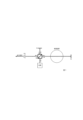
- FIG. 1 shows a sound measuring device using a Michelson interferometer.
- the sound measurement device in FIG. 1 includes a Michelson interferometer, a sound measurement unit, and a photodetector.
- a Michelson interferometer also includes a beam splitter and two mirrors.
- the sound measurement unit is a component that modulates the phase of light using sound. Note that a laser can be used as the light source.
- BS, M, and PD in FIG. 1 represent beam splitters, mirrors, and photodetectors, respectively. Arrows represent how light is branched and propagated.
- a beam splitter splits the light emitted from the light source into two beams.
- the two lights then propagate on different paths within the interferometer, and at least one of the lights passes through the sound measuring section.
- the two lights are then combined by a beam splitter.
- the phase difference between the two lights is taken out as an electrical signal.
- the current i of the electrical signal (output signal) that is the output of the photodetector is expressed by the following equation.
- ⁇ is the quantum efficiency of the photodetector
- I is the light intensity of the interference light
- I DC is the DC component of the light intensity of the interference light (average light intensity)
- I A is the amplitude of the interference fringes
- ⁇ 0 is due to factors other than sound. This is the amount of optical phase modulation.
- the current i of the output signal of the sound measurement device in FIG. 1 is obtained by adding the intensity I A cos( ⁇ s + ⁇ 0 ) indicating the influence of interference including the optical phase modulation amount ⁇ s due to sound to the average light intensity I DC . obtained from the results.
- the amount of optical phase modulation ⁇ s caused by sound is very small and extremely small relative to the average optical intensity I DC .
- the average light intensity I DC contains noise caused by fluctuations in the intensity of the light source. Even if this noise is minute with respect to the average light intensity I DC , it cannot be ignored with respect to the optical phase modulation amount ⁇ s due to sound. Therefore, the minimum amount of optical phase modulation that can be detected by the sound measuring device is often determined. Therefore, in order to reduce the noise in the sound measuring device and improve the SN ratio, it is important to reduce the noise contained in the average light intensity IDC .
- an object of the present invention is to provide a technique for measuring the amount of optical phase modulation due to sound, which is not affected by noise contained in the average optical intensity.
- One aspect of the present invention is a sound measurement device for measuring an optical phase modulation amount ⁇ s due to sound, which includes an interferometer and a sound measurement unit that modulates the phase of light using sound, and is emitted from a light source From light, light including light optically phase-modulated by the sound measurement unit (hereinafter referred to as first light) and light different from the first light and including light optically phase-modulated by the sound measurement unit ( a first photodetector for obtaining an electrical signal from the first light (hereinafter referred to as a first electrical signal); and a first photodetector from the second light.
- first light light optically phase-modulated by the sound measurement unit
- first electrical signal a first photodetector for obtaining an electrical signal from the first light
- a second photodetector for obtaining an electrical signal (hereinafter referred to as a second electrical signal); and a differential signal generator for obtaining a differential signal, which is the difference between the first electrical signal and the second electrical signal.
- an optical phase modulation amount adjuster that adjusts the optical phase modulation amount ⁇ 0 due to factors other than sound by fixing the interferometer so that the phase of the interference fringes is at the mid-fringe using the differential signal as the error signal.
- phase of the optical phase-modulated light contained in the first light and the phase of the optical phase-modulated light contained in the second light are in an inverted relationship
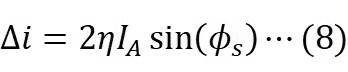
- optical phase modulation amount ⁇ s is measured as the current ⁇ i of the differential signal expressed by an equation using the fringe amplitude I A
- the first photodetector and the second photodetector are measured around a predetermined mid-fringe.
- the output voltage of the photodetector is adjusted to saturate when light that causes a phase variation exceeding the range of is input.
- the present invention it is possible to measure the amount of optical phase modulation due to sound without being affected by noise contained in the average optical intensity.
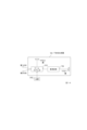
- FIG. 2 is a block diagram showing the configuration of the sound measuring device 100;
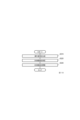
- FIG. 4 is a flowchart showing the operation of the sound measuring device 100;
- 3 is a block diagram showing the configuration of an interference light generator 110;
- FIG. 3 is a block diagram showing the configuration of an interference light generator 110;
- FIG. 3 is a block diagram showing the configuration of an interference light generator 110;
- FIG. 2 is a block diagram showing the configuration of a measurement sensitivity adjustment device 200;
- FIG. 4 is a flowchart showing the operation of the measurement sensitivity adjustment device 200;
- It is a figure which shows an example of the functional structure of the computer which implement
- ⁇ (caret) represents a superscript.
- x y ⁇ z means that y z is a superscript to x
- x y ⁇ z means that y z is a subscript to x
- _ (underscore) represents a subscript.
- x y_z means that y z is a superscript to x
- x y_z means that y z is a subscript to x.
- interference light is differentially detected in light-based sound measurement using the acousto-optic effect.
- the average light intensity can be canceled and the noise contained in the average light intensity can be removed. Therefore, the SN ratio can be greatly improved by removing the light intensity noise of the light source, which is the main noise in the conventional sound measuring device.
- a configuration example (hereinafter referred to as a basic configuration example) that serves as the base of the sound measurement device according to the embodiment of the present invention will be described.
- FIG. 2 is a diagram showing an example of the basic configuration of the sound measuring device.
- the sound measurement device in FIG. 2 is a configuration example using a Michelson interferometer, and includes a beam splitter, an interferometer, a sound measurement unit, two photodetectors, and a differential detection unit.
- the interferometer also includes a beam splitter and two mirrors.
- BS, M, and PD in FIG. 2 represent a beam splitter, a mirror, and a photodetector, respectively.
- a symbol with a cross on a circle represents a differential detection unit. Arrows represent how light is branched and propagated.
- a laser can be used as the light source.
- Any interferometer such as a Mach-Zehnder type or a Fizeau type can be used instead of the Michelson interferometer.
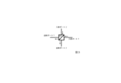
- Light emitted from the light source is split into two beams by the beam splitter of the interferometer. At least one of the lights passes through the sound measuring part one or more times. The two lights are each reflected by a mirror and enter the beam splitter of the interferometer and are combined. Light emitted from the two ports of the beam splitter (output port 1 and output port 2 in FIG. 3) is detected by a photodetector and converted into an electrical signal. A differential signal, which is the difference between the two electrical signals, is obtained as an output signal.
- the light emitted from the output port 1 is the sum of the component of the light incident from the incident port 1 that has passed through the beam splitter and the component of the light incident from the incident port 2 that has been reflected by the beam splitter.
- the light emitted from the exit port 2 is the sum of the component of the light incident from the entrance port 1 reflected by the beam splitter and the component of the light incident from the entrance port 2 transmitted through the beam splitter.
- the component of the light incident from the entrance port 1 reflected by the beam splitter and the component of the light incident from the entrance port 2 reflected by the beam splitter Either one is phase-inverted upon reflection. However, which component has its phase inverted depends on the structure and orientation of the beam splitter.
- the phase of the component of the light incident from the incident port 1 that is reflected by the beam splitter is reversed.
- E IN1 is the light incident from the entrance port 1
- E IN2 is the light incident from the entrance port 2
- the light E 1 emitted from the exit port 1 and the light E 2 emitted from the exit port 2 are Each can be represented by the following formula.
- the currents i1 and i2 of the electrical signals output from the two photodetectors PD1 and PD2 are respectively It can be expressed by the following formula. Therefore, the current ⁇ i of the differential signal, which is the output signal of the differential detection section, is expressed by the following equation. As can be seen from Equation (7), the differential signal current ⁇ i does not include a term including the average light intensity I DC . Therefore, it is possible to measure a low-noise sound that is not affected by noise caused by fluctuations in the intensity of the light source contained in the average light intensity, that is, the optical phase modulation amount ⁇ s caused by the sound.
- the sound measurement device may include a light amount adjuster (P in FIG. 4) for independently adjusting the amount of light incident on the two photodetectors.
- a linear polarizer can be used as the light amount adjuster.
- the two lights have the same polarization state. For example, if the two lights are linearly polarized light, the amount of light incident on the photodetector can be adjusted by rotating the linear polarizer. In this way, by providing the light amount adjuster in the sound measurement device of FIG. It can solve the problem of no amplitude.
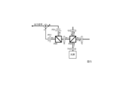
- FIG. 5 is a diagram showing an example of the basic configuration of the sound measuring device.
- the sound measurement device in FIG. 5 is a configuration example of an interferometer using a polarizing element, and includes an interferometer, a sound measurement section (not shown), two photodetectors, and a differential detection section.
- the interferometer includes two polarizing beam splitters, two half-wave plates, two quarter-wave plates and two mirrors (not shown).
- PBS, H, and Q in FIG. 5 represent a polarizing beam splitter, a half-wave plate, and a quarter-wave plate, respectively.
- the light emitted from the light source is linearly polarized light.
- Linearly polarized light emitted from a light source is converted into linearly polarized light inclined at 45° by a half-wave plate (a half-wave plate located near the light source).
- This converted linearly polarized light is split into orthogonal linearly polarized light by a polarization beam splitter.
- Each of the two linearly polarized light beams is transmitted through the quarter-wave plate twice, its direction is rotated by 90°, and it returns to the polarizing beam splitter again at a port different from the port where the two linearly polarized light beams were incident ( The light is output from the port that emits to the left of the This light is a superposition of two orthogonal linearly polarized light.
- the directions of the two linearly polarized light beams are rotated by 45° with a half-wave plate. This is split by another polarization beam splitter and detected by two photodetectors PD1 and PD2.
- the electric signal currents output from the two photodetectors PD1 and PD2 are equal to the currents i 1 and i 2 of the equations (5) and (6) except for the constant term. Therefore, the current ⁇ i of the differential signal, which is the output signal of the differential detection section, is expressed by Equation (7).
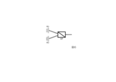
- the sound measuring device can be configured using a Wollaston prism (WP in FIG. 6).
- FIG. 6 shows a configuration example of a sound measuring device in which the polarizing beam splitter positioned near the photodetector in FIG. 5 is replaced with a Wollaston prism.
- a Wollaston prism separates the two linearly polarized light from the same plane into different directions. Therefore, by using a Wollaston prism, it is possible to detect with two photodetectors arranged in the same plane without using additional optical elements.
- FIG. 7 is a diagram illustrating an example of a configuration of a sound measuring device;
- the sound measurement device in FIG. 7 includes an interferometer that performs feedback control using a differential signal that is an output signal, and further includes a feedback controller and a piezo element (PZT in FIG. 7) for the feedback control. It is different from the sound measuring device of FIG. 2 in this point.
- a component including the feedback controller and the piezo element is called an optical phase modulation amount adjuster.
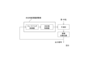
- an optical phase modulation amount adjuster includes a feedback controller and an optical phase controller, as shown in FIG.
- the optical phase modulation amount adjuster adjusts the optical phase modulation amount ⁇ 0 due to factors other than sound by using the differential signal as an error signal and fixing the interferometer so that the phase of the interference fringes is at the mid-fringe.
- the differential photodetector in FIG. 8 is a component including two photodetectors and a differential detection section.
- the optical phase modulation amount ⁇ 0 is adjusted by controlling the position of the mirror in the reference optical path with the piezo element as the optical phase controller.
- the reference optical path is an optical path in the interferometer that passes through the beam splitter, is reflected by the mirror, and passes through the beam splitter.
- An optical path that passes through the interferometer in order of the beam splitter and the sound measurement section, is reflected by a mirror, and passes through the sound measurement section and the beam splitter in order is called a measurement optical path. Note that the adjustment of the optical phase modulation amount is performed in a frequency band lower than the frequency of the sound to be measured.
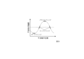
- FIG. 9 shows the relationship between the phase of interference fringes and the intensity (light amount) of interference light.
- the points where the intensity of the interference light is minimum and maximum are called a dark fringe and a bright fringe, respectively.
- a middle point between the dark fringe and the bright fringe is called a mid fringe.
- the light intensity change to phase change ie the sensitivity of the interferometer
- the sensitivity of the interferometer can be maximized by fixing the interferometer so that the phase of the interference fringes is always at the mid-fringe when there is no sound to be measured.
- This method of controlling an interferometer is called a mid-fringe lock.
- the optical phase modulation amount adjuster is a component for mid-fringe locking the interferometer.
- the amount of optical phase modulation ⁇ s due to sound depends on the sound whose fluctuation amount and frequency are to be measured.
- the optical phase modulation amount ⁇ 0 due to factors other than sound includes a stationary term determined by the arrangement of the optical system and a gradual fluctuation caused by air fluctuations, ground vibrations, and the like.
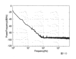
- the power of the optical phase modulation amount ⁇ 0 increases as the frequency component decreases, and the component below 100 Hz is dominant.
- the fluctuation amount of the optical phase modulation amount ⁇ 0 is set to zero (that is, the optical phase modulation amount ⁇ 0 is fixed at a certain constant )
- the fluctuation of the optical phase modulation amount ⁇ s can be left as it is.
- the current ⁇ i of the differential signal which is the output signal of the differential detection section, is expressed by the following equation.
- ⁇ s ⁇ 1 holds for general sounds, the current ⁇ i of the differential signal can be approximated by the following equation.
- the current ⁇ i of the differential signal and the amount of optical phase modulation ⁇ s due to the sound will have a proportional relationship, and the differential signal itself will be low noise. sound signal.
- a differential signal is input to the feedback controller as an error signal.
- the feedback controller cancels the variation of the optical phase modulation amount ⁇ 0 due to elements other than sound (the variation of the optical phase modulation amount ⁇ 0 due to elements other than sound becomes zero) with respect to this error signal.
- Generate control signals This can be achieved by making the control band lower than the sound frequency as described above.
- the feedback controller includes, for example, an electric circuit consisting of single or multiple amplifiers and integrators, a PID controller, a digital circuit, etc., and an optical phase controller so that the error signal becomes zero in a band containing no sound.
- the optical phase controller is driven using the control signal, which is the output signal of the feedback controller.
- the optical phase controller controls the position of the mirror in the reference optical path or the mirror in the measurement optical path, or the light propagating in the reference optical path (reference light) or the measurement optical path by an optical phase modulator inserted in the middle of the reference optical path or the measurement optical path. to control the phase of the light (measurement light) propagating through
- the method of controlling the position of the mirror for example, by driving a piezo element attached to the mirror with a control signal and expanding or contracting the reference light path or the measurement light path, the phase difference between the two lights is controlled, and the interference fringes are formed in the mid fringe. Secure (see Figure 7).
- an optical phase modulator inserted in the middle of the reference light path or the measurement light path is driven with a control signal to control the phase of the reference light or the measurement light. It controls the phase difference of the two lights and fixes the interference fringes to the midfringes.
- the interferometer is input with the sound to be measured and factors other than the sound ( disturbance ). Continue feedback control. As a result, only the optical phase modulation amount ⁇ s due to sound is output from the interferometer. Therefore, a low-noise differential signal proportional to the optical phase modulation amount ⁇ s can be obtained.
- the mid-fringe lock can be realized by performing feedback control using the differential signal as the error signal.
- the control band lower than the frequency of the sound to be measured, it becomes possible to measure the sound at the point of maximum sensitivity near the mid-fringe.
- the optical phase modulation amount ⁇ s and the current ⁇ i of the differential signal have a proportional relationship, making it possible to extract a low-noise sound signal without post-processing the differential signal. becomes.
- the measurement sensitivity of the sound measurement device of FIG. 7 is proportional to the amplitude IA of the interference fringes detected by the photodetector.
- the amplitude I A of the interference fringes is usually adjusted so that the output voltage of the photodetector included in the sound measuring device is not saturated. Therefore, the measurement sensitivity of the sound measurement device is limited by the saturation output voltage of the photodetector. A method for increasing the measurement sensitivity of the sound measuring device above the limitation due to the saturation output voltage of the photodetector will be described below.
- the voltage v of the differential signal is represented by the following formula.
- C appearing on the right side of equation (10) is the measurement sensitivity, and its unit is V/rad.
- Measurement sensitivity C is a value that depends on the amount of light incident on the photodetector, the quantum efficiency of the photodetector, the amplification factor of the photodetector, etc., and adjusts the amount of light emitted from the light source and the amplification factor of the photodetector. By doing so, the measurement sensitivity C can be adjusted.
- the measurement sensitivity of the sound measurement device is increased by intentionally saturating the output voltage of the photodetector. That is, the measurement sensitivity is adjusted so that C> Vout by either increasing the amount of light emitted from the light source or increasing the amplification factor of the photodetector (hereinafter referred to as C> V out is called the saturation condition).
- the saturation of the photodetector can be achieved by adjusting the amount of light emitted from the light source and the amplification factor of the photodetector.
- the sound measurement device 100 receives light emitted from a light source and measures an optical phase modulation amount ⁇ s due to sound.
- FIG. 12 is a block diagram showing the configuration of the sound measuring device 100.
- FIG. FIG. 13 is a flow chart showing the operation of the sound measuring device 100.
- the sound measuring device 100 includes an interference light generator 110 and two photodetectors 120 (hereinafter referred to as a first photodetector 120-1 and a second photodetector 120-2). , a differential signal generator 130 and an optical phase modulation amount adjuster 140 .
- the interference light generator 110 also includes interferometers 111/112/113 and a sound measuring section 114 that modulates the phase of light using sound.
- the interference light generator 110 receives the light emitted from the light source 910, and generates light including light phase-modulated by the sound measurement unit 114 from the light emitted from the light source (hereinafter referred to as first light). ) and light containing light phase-modulated by the sound measuring unit 114 (hereinafter referred to as second light), which is different from the first light, are obtained and output.
- the phase of the optical phase-modulated light contained in the first light and the phase of the optical phase-modulated light contained in the second light have an inverted relationship.
- the first photodetector 120-1 receives the first light output in S110, obtains an electrical signal from the first light (hereinafter referred to as a first electrical signal), and outputs the signal. .
- the second photodetector 120-2 receives the second light output in S110, obtains an electrical signal (hereinafter referred to as a second electrical signal) from the second light, and outputs the electrical signal. .
- the sound measuring device 100 includes a first light amount adjuster (not shown) for adjusting the light amount of the first light and a second and a second light amount adjuster (not shown) that adjusts the light amount of the light.
- the differential signal generator 130 receives the first electrical signal output in S120-1 and the second electrical signal output in S120-2, and receives the first electrical signal and the second electrical signal. A differential signal, which is the difference between them, is obtained and output.
- the optical phase modulation amount adjuster 140 receives the differential signal output in S130 as an input, uses the differential signal as an error signal, and fixes the interferometer 111 so that the phase of the interference fringes is at the mid-fringe. , to adjust the optical phase modulation amount ⁇ 0 due to factors other than sound.
- a configuration example of the interference light generator 110 will be described below.
- interference light generator 110 includes interferometer 111 (not shown) and sound measuring section 114 .
- the interferometer 111 includes a beam splitter 1111 and two mirrors 1112 (hereinafter referred to as first mirror 1112-1 and second mirror 1112-2).
- the sound measuring device 100 including the interferometer 111 corresponds to (basic configuration example 1) described in ⁇ Technical background>.
- the sound measurement device 100 may be configured to include a beam splitter (not shown) near the second photodetector 120-2, as shown in FIG.
- the light propagating along the first optical path in the interference light generator 110 passes through the beam splitter 1111 and the sound measuring section 114 in that order, is reflected by the first mirror 1112-1, and passes through the sound measuring section 114 and the beam splitter 1111.
- the sequentially passing light and the light propagating along the second optical path in the interference light generator 110 pass through the beam splitter 1111, are reflected by the second mirror 1112-2, and pass through the beam splitter 1111
- the first light and the second light are split by the beam splitter 1111 into light propagating on the first optical path in the interference light generator 110 and light propagating on the second optical path in the interference light generator 110. is the light obtained by
- interference light generator 110 includes interferometer 112 (not shown) and sound measuring section 114 .
- the interferometer 112 includes two polarizing beam splitters 1121 (hereinafter referred to as a first polarizing beam splitter 1121-1 and a second polarizing beam splitter 1121-2) and two half-wave plates 1122 (hereinafter referred to as a second 1 half-wave plate 1122-1, referred to as second half-wave plate 1122-2) and two quarter-wave plates 1123 (hereinafter referred to as first quarter-wave plate 1123-1, second two quarter-wave plates 1123-2) and two mirrors 1124 (hereinafter referred to as first mirror 1124-1 and second mirror 1124-2).
- the sound measuring device 100 including the interferometer 112 corresponds to (basic configuration example 2) described in ⁇ Technical background>.
- the light propagating on the first optical path in the interference light generator 110 is passed through the first half-wave plate 1122-1, the first polarization beam splitter 1121-1, and the first quarter-wave plate 1123-1. , the sound measuring section 114, and reflected by the first mirror 1124-1.
- 1/2 wavelength plate 1122-2, the light passing through the second polarization beam splitter 1121-2 in this order, and the light propagating through the second optical path in the interference light generator 110 are transferred to the first 1/2 wavelength plate 1122-1, the first polarizing beam splitter 1121-1, and the second quarter-wave plate 1123-2 in this order, reflected by the second mirror 1124-2, and passed through the second quarter-wave plate 1123.
- the positional relationship between the first quarter-wave plate 1123-1 and the sound measurement unit 114 is such that the first quarter-wave plate 1123-1 is on the left and the sound measurement unit 114 is on the right.
- the relationship may be reversed.
- the light propagating along the first optical path in the interference light generator 110 includes the first half-wave plate 1122-1, the first polarization beam splitter 1121-1, the sound measuring section 114, the first The light passes through the quarter-wave plate 1123-1 in order, is reflected by the first mirror 1124-1, is first quarter-wave plate 1123-1, the sound measurement section 114, and the first polarization beam splitter 1121-1. , second half-wave plate 1122-2, and second polarization beam splitter 1121-2 in this order.
- interference light generator 110 includes interferometer 113 (not shown) and sound measuring section 114 .
- the interferometer 113 includes a polarizing beam splitter 1131, a Wollaston prism 1132, and two half-wave plates 1133 (hereinafter referred to as the first half-wave plate 1133-1, the second half-wave plate 1133- 2), two quarter-wave plates 1134 (hereinafter referred to as first quarter-wave plate 1134-1 and second quarter-wave plate 1134-2), and two mirrors 1135 (hereinafter referred to as First mirror 1135-1, second mirror 1135-2).
- the sound measuring device 100 including the interferometer 113 corresponds to (modification) of (basic configuration example 2) described in ⁇ Technical background>.
- the light propagating on the first optical path in the interference light generator 110 is passed through the first half-wave plate 1133-1, the polarizing beam splitter 1131, the first quarter-wave plate 1134-1, and the sound measurement unit 114. and reflected by the first mirror 1135-1, the sound measurement unit 114, the first quarter-wave plate 1134-1, the polarization beam splitter 1131, the second half-wave plate 1133-2,
- the light passing through the Wollaston prism 1132 in this order and the light propagating along the second optical path in the interference light generator 110 are passed through the first half-wave plate 1133-1, the polarizing beam splitter 1131, and the second quarter-wave plate 1133-1.
- the first light and the second light are the light propagating on the first optical path in the interference light generator 110 in the Wollaston prism 1132 and the light in the interference light generator 110 .
- This light is obtained by branching the light propagating on the second optical path of .
- the positional relationship between the first quarter-wave plate 1134-1 and the sound measurement unit 114 is such that the first quarter-wave plate 1134-1 is on the left and the sound measurement unit 114 is on the right.
- the relationship may be reversed.
- the light propagating along the first optical path in the interference light generator 110 includes the first half-wave plate 1133-1, the polarization beam splitter 1131, the sound measurement section 114, and the first quarter-wave plate. 1134-1 in order, reflected by the first mirror 1135-1, the first quarter-wave plate 1134-1, the sound measurement unit 114, the polarization beam splitter 1131, the second half-wave plate 1133 ⁇ 2, and the light passing through the Wollaston prism 1132 in this order.
- the optical phase modulation amount adjuster 140 uses the differential signal to generate signals other than sound in a frequency band lower than the frequency of the sound to be measured.
- a control signal is generated for controlling the amount of variation in the amount of optical phase modulation ⁇ 0 due to elements to be zero (that is, the value of the amount ⁇ 0 of optical phase modulation due to elements other than sound becomes a certain constant), and the control signal is generated.
- the modulation amount ⁇ 0 is adjusted and the interferometers 111/112/113 are fixed so that the phase of the interference fringes is at the mid-fringe.
- the optical phase modulation amount adjuster 140 uses the control signal to drive the piezo elements attached to the first mirrors 1112-1/1124-1/1135-1, and the first mirrors in the interference light generator 110
- the phase difference between the light propagating on the first optical path in the interference light generator 110 and the light propagating on the second optical path in the interference light generator 110 may be controlled by expanding and contracting the optical path of
- the optical phase modulation amount adjuster 140 uses the control signal to drive the piezo elements attached to the second mirrors 1112-2/1124-2/1135-2 so that the second mirror in the interference light generator 110
- the phase difference between the light propagating on the first optical path in the interference light generator 110 and the light propagating on the second optical path in the interference light generator 110 may be controlled by expanding and contracting the optical path of good.
- the optical phase modulation amount adjuster 140 uses the control signal to adjust the beam splitter 1111 and the first mirror 1112-1 on the first optical path in the interference light generator 110/between the polarization beam splitter 1121-1 and the beam splitter 1121-1.
- Light propagating on the first optical path in the interference light generator 110 by driving the optical phase modulator inserted between the first mirror 1124-1/between the polarizing beam splitter 1131 and the first mirror 1135-1
- the optical phase modulation amount adjuster 140 uses the control signal to adjust the beam splitter 1111 and the second mirror 1112-2 on the second optical path in the interference light generator 110/polarization beam splitter 1121-1.
- the phase difference between the light propagating along the first optical path within the interference light generator 110 and the light propagating along the second optical path within the interference light generator 110 is controlled. good too.
- the embodiment of the present invention it is possible to measure the amount of optical phase modulation due to sound without being affected by noise included in the average optical intensity.
- the two photodetectors 120 included in the sound measuring device 100 detect that, when light that causes a phase change exceeding a predetermined range around the mid-fringe is input, the light
- the detector output voltage may be adjusted to saturate.
- the two photodetectors 120 may be adjusted so that the output voltage of the photodetectors is saturated by adjusting the amount of light emitted from the light source.
- the output voltage of the photodetector may be adjusted to be saturated.
- the measurement sensitivity adjustment device 200 that adjusts the output voltage of the photodetector 120 included in the sound measurement device 100 will be described.
- FIG. 17 is a block diagram showing the configuration of the measurement sensitivity adjustment device 200.
- FIG. 18 is a flow chart showing the operation of the measurement sensitivity adjustment device 200.
- measurement sensitivity adjustment device 200 includes sweep signal generation section 210 , measurement sensitivity measurement section 220 , and measurement sensitivity adjustment section 230 .
- the sweep signal generation unit 210 generates a sweep signal as an input signal of the optical phase modulation amount adjuster 140 such that the differential signal corresponds to fluctuations of one cycle or more of the interference fringes, and performs optical phase modulation. Output to quantity adjuster 140 .
- Any periodic signal such as a triangular wave can be used as the sweep signal.
- the measurement sensitivity measuring unit 220 receives the interference light output from the interference light generator 110, and measures the measurement sensitivity using the interference light.
- the measurement sensitivity is the amplitude of the sine wave generated by the interference fringes. Therefore, the measurement sensitivity measuring section 220 can measure the measurement sensitivity using the following two methods.
- Method 1 Method based on observation of amplitude of interference fringes
- the differential signal corresponds to fluctuations of one period or more of the interference fringes. Since the measurement sensitivity is equal to the amplitude of the sine wave generated by the interference fringes, the measurement sensitivity can be obtained from the amplitude. However, since the interference fringes are saturated in the region where the output voltage of the photodetector is saturated, the amplitude cannot be measured directly from the waveform.
- a filter that attenuates the amount of light by a known constant amount (hereinafter referred to as an attenuation filter) is installed on the optical path. After temporarily reducing the light intensity to a brightness that does not saturate the interference fringes with an attenuation filter, the amplitude is directly observed from the waveform, and the amplitude value obtained from the observation is multiplied by a coefficient that corrects the attenuation due to the attenuation filter. to obtain the measurement sensitivity.
- an attenuation filter for example, an ND filter or a polarizer and wave plate can be used. After the adjustment of the measurement sensitivity is completed, the attenuation filter installed for the adjustment is removed, so that the sound measurement device 100 can perform measurement with the adjusted measurement sensitivity.
- the amplification factor of the photodetector may be adjusted instead of using the attenuation filter.
- the amount of light is temporarily reduced to a brightness that does not saturate the interference fringes.
- the measurement sensitivity may be obtained by multiplying by a coefficient for correcting the adjustment by .
- Method 2 Method based on measurement of phase at saturation of photodetector output voltage
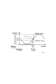
- Observe the output voltage of the photodetector using an oscilloscope or the like. Assume that the phase is zero at the mid-fringe, measure the phase ⁇ at the time of saturation of the output voltage of the photodetector, and obtain the measurement sensitivity C from C V out /sin( ⁇ ).
- the measurement sensitivity adjustment unit 230 receives the measurement sensitivity output from the measurement sensitivity measurement unit 220, and adjusts the sound measurement device 100 so that the measurement sensitivity becomes a desired value. Adjustment of the sound measuring device 100 may or may not be performed by human intervention. Further, the adjustment of the sound measurement device 100 may be performed by either a method of adjusting the amount of light emitted from the light source or a method of adjusting the amplification factor of the photodetector. In addition, any method that can adjust the output voltage of the photodetector, such as a method of adjusting a light amount adjuster installed on the optical path, a method of adjusting the position of the light beam input to the photodetector, etc. may be used to adjust the sound measurement device 100 .
- the embodiment of the present invention it is possible to measure the amount of optical phase modulation due to sound without being affected by noise included in the average optical intensity.
- the amount of optical phase modulation due to sound can be detected with high sensitivity. Measurement becomes possible.
- FIG. 19 is a diagram showing an example of the functional configuration of a computer 2000 that implements each of the devices described above.
- the processing in each device described above can be performed by causing the recording unit 2020 to read a program for causing the computer 2000 to function as each device described above, and causing the control unit 2010, the input unit 2030, the output unit 2040, and the like to operate.
- the apparatus of the present invention includes, for example, a single hardware entity, which includes an input unit to which a keyboard can be connected, an output unit to which a liquid crystal display can be connected, and a communication device (for example, a communication cable) capable of communicating with the outside of the hardware entity.
- a communication device for example, a communication cable
- CPU Central Processing Unit
- memory RAM and ROM hard disk external storage device
- input unit, output unit, communication unit a CPU, a RAM, a ROM, and a bus for connecting data to and from an external storage device.
- the hardware entity may be provided with a device (drive) capable of reading and writing a recording medium such as a CD-ROM.
- a physical entity with such hardware resources includes a general purpose computer.
- the external storage device of the hardware entity stores a program necessary for realizing the functions described above and data required for the processing of this program (not limited to the external storage device; It may be stored in a ROM, which is a dedicated storage device). Data obtained by processing these programs are appropriately stored in a RAM, an external storage device, or the like.
- each program stored in an external storage device or ROM, etc.
- the data necessary for processing each program are read into the memory as needed, and interpreted, executed and processed by the CPU as appropriate.
- the CPU realizes a predetermined function (each structural unit represented by the above, . . . unit, . . . means, etc.).
- a program that describes this process can be recorded on a computer-readable recording medium.
- Any computer-readable recording medium may be used, for example, a magnetic recording device, an optical disk, a magneto-optical recording medium, a semiconductor memory, or the like.
- magnetic recording devices hard disk devices, flexible disks, magnetic tapes, etc., as optical discs, DVD (Digital Versatile Disc), DVD-RAM (Random Access Memory), CD-ROM (Compact Disc Read Only Memory), CD-R (Recordable) / RW (ReWritable), etc.
- magneto-optical recording media such as MO (Magneto-Optical disc), etc. as semiconductor memory, EEP-ROM (Electronically Erasable and Programmable-Read Only Memory), etc. can be used.
- this program is carried out, for example, by selling, assigning, lending, etc. portable recording media such as DVDs and CD-ROMs on which the program is recorded.
- the program may be distributed by storing the program in the storage device of the server computer and transferring the program from the server computer to other computers via the network.
- a computer that executes such a program for example, first stores the program recorded on a portable recording medium or the program transferred from the server computer once in its own storage device. When executing the process, this computer reads the program stored in its own storage device and executes the process according to the read program. Also, as another execution form of this program, the computer may read the program directly from a portable recording medium and execute processing according to the program, and the program is transferred from the server computer to this computer. Each time, the processing according to the received program may be executed sequentially. In addition, the above-mentioned processing is executed by a so-called ASP (Application Service Provider) type service, which does not transfer the program from the server computer to this computer, and realizes the processing function only by its execution instruction and result acquisition. may be It should be noted that the program in this embodiment includes information that is used for processing by a computer and that conforms to the program (data that is not a direct instruction to the computer but has the property of prescribing the processing of the computer, etc.).
- ASP Application Service Provide
- a hardware entity is configured by executing a predetermined program on a computer, but at least part of these processing contents may be implemented by hardware.
Landscapes
- Physics & Mathematics (AREA)
- General Physics & Mathematics (AREA)
- Measurement Of Mechanical Vibrations Or Ultrasonic Waves (AREA)
Abstract
Description


本発明の実施形態では、音響光学効果を用いた光による音計測において、干渉光を差動検出する。これにより、平均光強度を相殺し、平均光強度に含まれる雑音を除去することができる。したがって、従来の音計測装置における主要な雑音である、光源の光強度雑音を除去することによって、SN比を大幅に向上させることができる。また、同程度のSN比を実現しようとする場合における光源の強度安定性に対する要求を大幅に低下させることができ、コスト削減が可能となる。
図2は、音計測装置の基本構成の一例を示す図である。図2の音計測装置は、マイケルソン干渉計による構成例であり、ビームスプリッタと、干渉計と、音測定部と、2つの光検出器と、差動検出部を含む。また、干渉計は、ビームスプリッタと2つの鏡を含む。図2中のBS, M, PDはそれぞれビームスプリッタ、鏡、光検出器を表す。〇に十字の記号は、差動検出部を表す。また、矢印は光が分岐、伝搬する様子を表す。
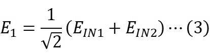
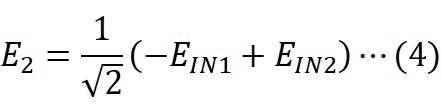
I1を光EIN1の強度(光量)、I2を光EIN2の強度(光量)とすると、2つの光検出器PD1, PD2から出力される電気信号の電流i1, i2は、それぞれ以下の式で表すことができる。


図5は、音計測装置の基本構成の一例を示す図である。図5の音計測装置は、偏光素子を用いた干渉計による構成例であり、干渉計と、音測定部(図示しない)と、2つの光検出器と、差動検出部を含む。干渉計は、2つの偏光ビームスプリッタと2つの1/2波長板と2つの1/4波長板と2つの鏡(図示しない)を含む。図5中のPBS, H, Qはそれぞれ偏光ビームスプリッタ、1/2波長板、1/4波長板を表す。
なお、図6に示すように、音計測装置は、ウォラストンプリズム(図6中のWP)を用いて構成することができる。図6は、図5の光検出器の近くに位置する偏光ビームスプリッタをウォラストンプリズムで置き換えた音計測装置の構成例を示すものである。ウォラストンプリズムによって2つの直線偏光は同じ面から異なる方向に分離される。したがって、ウォラストンプリズムを用いることにより、追加の光学素子を用いることなく、同一平面に配置された2つの光検出器で検出することが可能となる。
図7は、音計測装置の構成の一例を示す図である。図7の音計測装置は、出力信号である差動信号によるフィードバック制御を行う干渉計を含むものであり、当該フィードバック制御のためにフィードバック制御器とピエゾ素子(図7中のPZT)をさらに含む点において、図2の音計測装置と異なる。ここで、フィードバック制御器とピエゾ素子とを含む構成部を光位相変調量調整器という。一般に、光位相変調量調整器は、図8に示すように、フィードバック制御器と光位相制御器を含む。光位相変調量調整器は、差動信号を誤差信号として、干渉縞の位相がミッドフリンジにあるように干渉計を固定することで、音以外の要素による光位相変調量φ0を調整する。なお、図8の差動光検出器とは、2つの光検出器と差動検出部を含む構成部である。図7の音計測装置では、光位相制御器であるピエゾ素子が参照光路の鏡の位置を制御することにより、光位相変調量φ0を調整する。ここで、参照光路とは、干渉計内を、ビームスプリッタを通過し、鏡で反射され、ビームスプリッタを通過する光路のことである。また、干渉計内を、ビームスプリッタ、音測定部の順に通過し、鏡で反射され、音測定部、ビームスプリッタの順に通過する光路のことを測定光路という。なお、光位相変調量の調整は、計測対象となる音の周波数よりも低い周波数帯域で行う。


音計測装置100は、光源から射出された光を入力とし、音による光位相変調量φsを計測する。
図14に示すように干渉光生成器110は、干渉計111(図示しない)と、音測定部114とを含む。干渉計111は、ビームスプリッタ1111と、2つの鏡1112(以下、第1の鏡1112-1、第2の鏡1112-2という)とを含む。干渉計111を含む音計測装置100は、<技術的背景>で説明した(基本構成例1)に相当する。音計測装置100は、図2にあるように、第2の光検出器120-2の近くにビームスプリッタ(図示しない)を含む構成であってもよい。
図15に示すように干渉光生成器110は、干渉計112(図示しない)と、音測定部114とを含む。干渉光計112は、2つの偏光ビームスプリッタ1121(以下、第1の偏光ビームスプリッタ1121-1、第2の偏光ビームスプリッタ1121-2という)と、2つの1/2波長板1122(以下、第1の1/2波長板1122-1、第2の1/2波長板1122-2という)と、2つの1/4波長板1123(以下、第1の1/4波長板1123-1、第2の1/4波長板1123-2という)と、2つの鏡1124(以下、第1の鏡1124-1、第2の鏡1124-2という)とを含む。干渉計112を含む音計測装置100は、<技術的背景>で説明した(基本構成例2)に相当する。
図16に示すように干渉光生成器110は、干渉計113(図示しない)と、音測定部114とを含む。干渉計113は、偏光ビームスプリッタ1131と、ウォラストンプリズム1132と、2つの1/2波長板1133(以下、第1の1/2波長板1133-1、第2の1/2波長板1133-2という)と、2つの1/4波長板1134(以下、第1の1/4波長板1134-1、第2の1/4波長板1134-2という)と、2つの鏡1135(以下、第1の鏡1135-1、第2の鏡1135-2という)とを含む。干渉計113を含む音計測装置100は、<技術的背景>で説明した(基本構成例2)の(変形例)に相当する。
<技術的背景>で説明したように、音計測装置100に含まれる2つの光検出器120は、予め定めたミッドフリンジ周辺の範囲を超える位相変動を生じさせる光が入力された場合、当該光検出器の出力電圧が飽和するように調整されていてもよい。その際、2つの光検出器120は、光源から射出される光の光量を調整することにより、当該光検出器の出力電圧が飽和するように調整されていてもよいし、当該光検出器の増幅倍率を調整することにより、当該光検出器の出力電圧が飽和するように調整されていてもよい。
S210において生成された掃引信号を用いると、差動信号は干渉縞1周期分以上の変動に対応するものとなる。そして、計測感度は干渉縞が生成する正弦波の振幅に等しいので、当該振幅から計測感度を求めることができる。しかし、光検出器の出力電圧が飽和する領域では干渉縞は飽和しているため、波形から直接振幅を測定することができない。
オシロスコープなどを用いて光検出器の出力電圧を観測する。ミッドフリンジにおける位相のゼロとし、光検出器の出力電圧の飽和時における位相θを測定し、C=Vout/sin(θ)により計測感度Cを求める。
図19は、上述の各装置を実現するコンピュータ2000の機能構成の一例を示す図である。上述の各装置における処理は、記録部2020に、コンピュータ2000を上述の各装置として機能させるためのプログラムを読み込ませ、制御部2010、入力部2030、出力部2040などに動作させることで実施できる。
Claims (8)
- 音による光位相変調量φsを計測する音計測装置であって、
干渉計と音を用いて光の位相を変調する音測定部とを含み、光源から射出された光から、前記音測定部により光位相変調した光を含む光(以下、第1の光という)と、前記第1の光とは異なる、前記音測定部により光位相変調した光を含む光(以下、第2の光という)とを得る干渉光生成器と、
前記第1の光から電気信号(以下、第1の電気信号という)を得る第1光検出器と、
前記第2の光から電気信号(以下、第2の電気信号という)を得る第2光検出器と、
前記第1の電気信号と前記第2の電気信号からその差分である差動信号を得る差動信号生成器と、
前記差動信号を誤差信号として、干渉縞の位相がミッドフリンジにあるように前記干渉計を固定することで、音以外の要素による光位相変調量φ0を調整する光位相変調量調整器とを含み、
前記第1の光に含まれる光位相変調した光の位相と前記第2の光に含まれる光位相変調した光の位相は、反転した関係にあり、
前記光位相変調量φsは、干渉縞の振幅IAを用いた式により表される前記差動信号の電流Δiとして計測され、
前記第1の光検出器と前記第2の光検出器は、予め定めたミッドフリンジ周辺の範囲を超える位相変動を生じさせる光が入力された場合、当該光検出器の出力電圧が飽和するように調整されている
音計測装置。 - 請求項1に記載の音計測装置であって、
前記第1の光検出器と前記第2の光検出器は、光源から射出される光の光量を調整することにより、当該光検出器の出力電圧が飽和するように調整されている
ことを特徴とする音計測装置。 - 請求項1に記載の音計測装置であって、
前記第1の光検出器と前記第2の光検出器は、当該光検出器の増幅倍率を調整することにより、当該光検出器の出力電圧が飽和するように調整されている
ことを特徴とする音計測装置。 - 請求項1に記載の音計測装置であって、
前記干渉計は、ビームスプリッタと、2つの鏡(以下、第1の鏡、第2の鏡という)とを含み、
前記干渉光生成器内の第1の光路を伝搬する光は、前記ビームスプリッタ、前記音測定部の順に通過し、前記第1の鏡で反射され、前記音測定部、前記ビームスプリッタの順に通過する光であり、
前記干渉光生成器内の第2の光路を伝搬する光は、前記ビームスプリッタを通過し、前記第2の鏡で反射され、前記ビームスプリッタを通過する光であり、
前記第1の光と前記第2の光は、前記ビームスプリッタにおいて前記干渉光生成器内の第1の光路を伝搬する光と前記干渉光生成器内の第2の光路を伝搬する光を分岐することにより、得られる光である
ことを特徴とする音計測装置。 - 請求項1に記載の音計測装置であって、
前記干渉計は、2つの偏光ビームスプリッタ(以下、第1の偏光ビームスプリッタ、第2の偏光ビームスプリッタという)と、2つの1/2波長板(以下、第1の1/2波長板、第2の1/2波長板という)と、2つの1/4波長板(以下、第1の1/4波長板、第2の1/4波長板という)と、2つの鏡(以下、第1の鏡、第2の鏡という)とを含み、
前記干渉光生成器内の第1の光路を伝搬する光は、前記第1の1/2波長板、前記第1の偏光ビームスプリッタ、前記第1の1/4波長板、前記音測定部の順に通過し、前記第1の鏡で反射され、前記音測定部、前記第1の1/4波長板、前記第1の偏光ビームスプリッタ、前記第2の1/2波長板、前記第2の偏光ビームスプリッタの順に通過する光であり、
前記干渉光生成器内の第2の光路を伝搬する光は、前記第1の1/2波長板、前記第1の偏光ビームスプリッタ、前記第2の1/4波長板の順に通過し、前記第2の鏡で反射され、前記第2の1/4波長板、前記第1の偏光ビームスプリッタ、前記第2の1/2波長板、前記第2の偏光ビームスプリッタの順に通過する光であり、
前記第1の光と前記第2の光は、前記第2の偏光ビームスプリッタにおいて前記干渉光生成器内の第1の光路を伝搬する光と前記干渉光生成器内の第2の光路を伝搬する光を分岐することにより、得られる光である
ことを特徴とする音計測装置。 - 請求項1に記載の音計測装置であって、
前記干渉計は、偏光ビームスプリッタと、ウォラストンプリズムと、2つの1/2波長板(以下、第1の1/2波長板、第2の1/2波長板という)と、2つの1/4波長板(以下、第1の1/4波長板、第2の1/4波長板という)と、2つの鏡(以下、第1の鏡、第2の鏡という)とを含み、
前記干渉光生成器内の第1の光路を伝搬する光は、前記第1の1/2波長板、前記偏光ビームスプリッタ、前記第1の1/4波長板、前記音測定部の順に通過し、前記第1の鏡で反射され、前記音測定部、前記第1の1/4波長板、前記偏光ビームスプリッタ、前記第2の1/2波長板、前記ウォラストンプリズムの順に通過する光であり、
前記干渉光生成器内の第2の光路を伝搬する光は、前記第1の1/2波長板、前記偏光ビームスプリッタ、前記第2の1/4波長板の順に通過し、前記第2の鏡で反射され、前記第2の1/4波長板、前記偏光ビームスプリッタ、前記第2の1/2波長板、前記ウォラストンプリズムの順に通過する光であり、
前記第1の光と前記第2の光は、前記ウォラストンプリズムにおいて前記干渉光生成器内の第1の光路を伝搬する光と前記干渉光生成器内の第2の光路を伝搬する光を分岐することにより、得られる光である
ことを特徴とする音計測装置。 - 音計測装置が、音による光位相変調量φsを計測する音計測方法であって、
前記音計測装置に含まれ、干渉計と音を用いて光の位相を変調する音測定部とを含む干渉光生成器が、光源から射出された光から、前記音測定部により光位相変調した光を含む光(以下、第1の光という)と、前記第1の光とは異なる、前記音測定部により光位相変調した光を含む光(以下、第2の光という)とを得る干渉光生成ステップと、
前記音計測装置に含まれる第1の光検出器が、前記第1の光から電気信号(以下、第1の電気信号という)を得る第1光検出ステップと、
前記音計測装置に含まれる第2の光検出器が、前記第2の光から電気信号(以下、第2の電気信号という)を得る第2光検出ステップと、
前記音計測装置に含まれる差動信号生成器が、前記第1の電気信号と前記第2の電気信号からその差分である差動信号を得る差動信号生成ステップと、
前記音計測装置に含まれる光位相変調量調整器が、前記差動信号を誤差信号として、干渉縞の位相がミッドフリンジにあるように前記干渉計を固定することで、音以外の要素による光位相変調量φ0を調整する光位相変調量調整ステップとを含み、
前記第1の光に含まれる光位相変調した光の位相と前記第2の光に含まれる光位相変調した光の位相は、反転した関係にあり、
前記光位相変調量φsは、干渉縞の振幅IAを用いた式により表される前記差動信号の電流Δiとして計測され、
前記第1の光検出器と前記第2の光検出器は、予め定めたミッドフリンジ周辺の範囲を超える位相変動を生じさせる光が入力された場合、当該光検出器の出力電圧が飽和するように調整されている
音計測方法。 - 請求項1ないし6のいずれか1項に記載の音計測装置としてコンピュータを機能させるためのプログラム。
Priority Applications (3)
| Application Number | Priority Date | Filing Date | Title |
|---|---|---|---|
| US18/702,396 US20240410741A1 (en) | 2021-10-28 | 2021-10-28 | Sound measurement apparatus, sound measurement method, and program |
| JP2023555986A JP7697523B2 (ja) | 2021-10-28 | 2021-10-28 | 音計測装置、音計測方法、プログラム |
| PCT/JP2021/039852 WO2023073873A1 (ja) | 2021-10-28 | 2021-10-28 | 音計測装置、音計測方法、プログラム |
Applications Claiming Priority (1)
| Application Number | Priority Date | Filing Date | Title |
|---|---|---|---|
| PCT/JP2021/039852 WO2023073873A1 (ja) | 2021-10-28 | 2021-10-28 | 音計測装置、音計測方法、プログラム |
Publications (1)
| Publication Number | Publication Date |
|---|---|
| WO2023073873A1 true WO2023073873A1 (ja) | 2023-05-04 |
Family
ID=86157569
Family Applications (1)
| Application Number | Title | Priority Date | Filing Date |
|---|---|---|---|
| PCT/JP2021/039852 Ceased WO2023073873A1 (ja) | 2021-10-28 | 2021-10-28 | 音計測装置、音計測方法、プログラム |
Country Status (3)
| Country | Link |
|---|---|
| US (1) | US20240410741A1 (ja) |
| JP (1) | JP7697523B2 (ja) |
| WO (1) | WO2023073873A1 (ja) |
Citations (3)
| Publication number | Priority date | Publication date | Assignee | Title |
|---|---|---|---|---|
| JPH035875Y2 (ja) * | 1984-08-20 | 1991-02-14 | ||
| JPH05172738A (ja) * | 1991-12-24 | 1993-07-09 | Jasco Corp | 音響セル |
| JPH11132718A (ja) * | 1997-10-31 | 1999-05-21 | Topcon Corp | 干渉計測装置及び干渉計測装置用プローブ |
-
2021
- 2021-10-28 JP JP2023555986A patent/JP7697523B2/ja active Active
- 2021-10-28 US US18/702,396 patent/US20240410741A1/en active Pending
- 2021-10-28 WO PCT/JP2021/039852 patent/WO2023073873A1/ja not_active Ceased
Patent Citations (3)
| Publication number | Priority date | Publication date | Assignee | Title |
|---|---|---|---|---|
| JPH035875Y2 (ja) * | 1984-08-20 | 1991-02-14 | ||
| JPH05172738A (ja) * | 1991-12-24 | 1993-07-09 | Jasco Corp | 音響セル |
| JPH11132718A (ja) * | 1997-10-31 | 1999-05-21 | Topcon Corp | 干渉計測装置及び干渉計測装置用プローブ |
Non-Patent Citations (1)
| Title |
|---|
| 光の位相で微弱な音を捉えます, YouTube[online][video]. 06 June 2021, <URL : https://www.youtube.com/watch?v=kjYQ2VQROec>, [retrieved on 11 January 2022] (Captures Weak sound with a phase of light) * |
Also Published As
| Publication number | Publication date |
|---|---|
| JP7697523B2 (ja) | 2025-06-24 |
| JPWO2023073873A1 (ja) | 2023-05-04 |
| US20240410741A1 (en) | 2024-12-12 |
Similar Documents
| Publication | Publication Date | Title |
|---|---|---|
| CN111623892A (zh) | 用于时变随机信号测量的自适应光纤型马赫曾德干涉仪 | |
| CN110081974B (zh) | 一种激光线宽测量系统 | |
| JPH07311182A (ja) | 光熱変位計測による試料評価方法 | |
| Schewe et al. | Differential laser Doppler vibrometry for displacement measurements down to 1 mHz with 1 nm amplitude resolution in harsh environments | |
| Li et al. | Joint measurement of multiple noncommuting parameters | |
| CN108801476A (zh) | 一种测量时变相位信号的光纤型自适应平衡零拍测量系统 | |
| Zhang et al. | Improved PGC-Arctan demodulation scheme with immunity to carrier phase delay and modulation depth | |
| JP4925139B2 (ja) | ディスパーション干渉計及び被測定物の物理量の計測方法 | |
| Jiang et al. | Multiple self-mixing interferometry algorithm based on phase modulation for vibration measurement | |
| Zhang et al. | An improved phase generated carrier demodulation scheme for sinusoidal phase-modulating interferometer to detect air-solid interface acoustic waves | |
| JPS60149903A (ja) | 干渉計光フアイバセンサの平衡方法および装置 | |
| JP7697523B2 (ja) | 音計測装置、音計測方法、プログラム | |
| Wu et al. | The improved denoising algorithm of acoustic sensor based on linear optical fiber Sagnac interferometer | |
| Wang et al. | Photothermal modulation of laser diode wavelength: application to sinusoidal phase-modulating interferometer for displacement measurements | |
| Zhang et al. | A PGC demodulation scheme based on the Lissajous ellipse fitting for homodyne interferometer without using second harmonic carrier signal | |
| JP7367877B2 (ja) | 音計測方法 | |
| Wang et al. | A low-noise, high-SNR and large-dynamic-range balanced homodyne detector for broadband squeezed light measurement | |
| Zhang et al. | High performance sinusoidal phase modulating interferometer based on fundamental frequency mixing PGC demodulation and balanced detection | |
| Feng et al. | Micro-vibration measurement using self-mixing interferometry with an intracavity frequency-doubling solid-state laser | |
| Zhang et al. | Frequency response of the non-polarization-maintaining depolarized sagnac interferometer based on maximum fringe contrast | |
| Wu et al. | Polarization phase-shifting multi-wavelength interferometric displacement measurement with nonlinear error compensation | |
| Wang et al. | Laser self-mixing interferometry based on phase-modulation and spectral inhibition for micro-displacement measurement | |
| Luna et al. | Signal-to-noise ratio measurement in a Mach-Zehnder interferometer using Risley Prisms and lock-in detection | |
| Chu et al. | Improved phase generated carrier demodulation algorithm for vibration sensing system based on distributed feedback fiber laser | |
| Huang et al. | Sensitivity normalization technique of PGC demodulation with low harmonic distortion and high stability using laser modulation to generate carrier signal |
Legal Events
| Date | Code | Title | Description |
|---|---|---|---|
| 121 | Ep: the epo has been informed by wipo that ep was designated in this application |
Ref document number: 21962421 Country of ref document: EP Kind code of ref document: A1 |
|
| WWE | Wipo information: entry into national phase |
Ref document number: 2023555986 Country of ref document: JP |
|
| WWE | Wipo information: entry into national phase |
Ref document number: 18702396 Country of ref document: US |
|
| NENP | Non-entry into the national phase |
Ref country code: DE |
|
| 122 | Ep: pct application non-entry in european phase |
Ref document number: 21962421 Country of ref document: EP Kind code of ref document: A1 |