WO2023073872A1 - 冷凍サイクル装置 - Google Patents
冷凍サイクル装置 Download PDFInfo
- Publication number
- WO2023073872A1 WO2023073872A1 PCT/JP2021/039845 JP2021039845W WO2023073872A1 WO 2023073872 A1 WO2023073872 A1 WO 2023073872A1 JP 2021039845 W JP2021039845 W JP 2021039845W WO 2023073872 A1 WO2023073872 A1 WO 2023073872A1
- Authority
- WO
- WIPO (PCT)
- Prior art keywords
- refrigerant
- heat exchanger
- compressor
- expansion valve
- flow path
- Prior art date
- Legal status (The legal status is an assumption and is not a legal conclusion. Google has not performed a legal analysis and makes no representation as to the accuracy of the status listed.)
- Ceased
Links
Images







Classifications
-
- F—MECHANICAL ENGINEERING; LIGHTING; HEATING; WEAPONS; BLASTING
- F25—REFRIGERATION OR COOLING; COMBINED HEATING AND REFRIGERATION SYSTEMS; HEAT PUMP SYSTEMS; MANUFACTURE OR STORAGE OF ICE; LIQUEFACTION SOLIDIFICATION OF GASES
- F25B—REFRIGERATION MACHINES, PLANTS OR SYSTEMS; COMBINED HEATING AND REFRIGERATION SYSTEMS; HEAT PUMP SYSTEMS
- F25B13/00—Compression machines, plants or systems, with reversible cycle
-
- F—MECHANICAL ENGINEERING; LIGHTING; HEATING; WEAPONS; BLASTING
- F25—REFRIGERATION OR COOLING; COMBINED HEATING AND REFRIGERATION SYSTEMS; HEAT PUMP SYSTEMS; MANUFACTURE OR STORAGE OF ICE; LIQUEFACTION SOLIDIFICATION OF GASES
- F25B—REFRIGERATION MACHINES, PLANTS OR SYSTEMS; COMBINED HEATING AND REFRIGERATION SYSTEMS; HEAT PUMP SYSTEMS
- F25B25/00—Machines, plants or systems, using a combination of modes of operation covered by two or more of the groups F25B1/00 - F25B23/00
- F25B25/005—Machines, plants or systems, using a combination of modes of operation covered by two or more of the groups F25B1/00 - F25B23/00 using primary and secondary systems
-
- F—MECHANICAL ENGINEERING; LIGHTING; HEATING; WEAPONS; BLASTING
- F25—REFRIGERATION OR COOLING; COMBINED HEATING AND REFRIGERATION SYSTEMS; HEAT PUMP SYSTEMS; MANUFACTURE OR STORAGE OF ICE; LIQUEFACTION SOLIDIFICATION OF GASES
- F25B—REFRIGERATION MACHINES, PLANTS OR SYSTEMS; COMBINED HEATING AND REFRIGERATION SYSTEMS; HEAT PUMP SYSTEMS
- F25B41/00—Fluid-circulation arrangements
- F25B41/30—Expansion means; Dispositions thereof
- F25B41/31—Expansion valves
-
- F—MECHANICAL ENGINEERING; LIGHTING; HEATING; WEAPONS; BLASTING
- F25—REFRIGERATION OR COOLING; COMBINED HEATING AND REFRIGERATION SYSTEMS; HEAT PUMP SYSTEMS; MANUFACTURE OR STORAGE OF ICE; LIQUEFACTION SOLIDIFICATION OF GASES
- F25B—REFRIGERATION MACHINES, PLANTS OR SYSTEMS; COMBINED HEATING AND REFRIGERATION SYSTEMS; HEAT PUMP SYSTEMS
- F25B49/00—Arrangement or mounting of control or safety devices
- F25B49/02—Arrangement or mounting of control or safety devices for compression type machines, plants or systems
-
- F—MECHANICAL ENGINEERING; LIGHTING; HEATING; WEAPONS; BLASTING
- F25—REFRIGERATION OR COOLING; COMBINED HEATING AND REFRIGERATION SYSTEMS; HEAT PUMP SYSTEMS; MANUFACTURE OR STORAGE OF ICE; LIQUEFACTION SOLIDIFICATION OF GASES
- F25B—REFRIGERATION MACHINES, PLANTS OR SYSTEMS; COMBINED HEATING AND REFRIGERATION SYSTEMS; HEAT PUMP SYSTEMS
- F25B2313/00—Compression machines, plants or systems with reversible cycle not otherwise provided for
- F25B2313/027—Compression machines, plants or systems with reversible cycle not otherwise provided for characterised by the reversing means
-
- F—MECHANICAL ENGINEERING; LIGHTING; HEATING; WEAPONS; BLASTING
- F25—REFRIGERATION OR COOLING; COMBINED HEATING AND REFRIGERATION SYSTEMS; HEAT PUMP SYSTEMS; MANUFACTURE OR STORAGE OF ICE; LIQUEFACTION SOLIDIFICATION OF GASES
- F25B—REFRIGERATION MACHINES, PLANTS OR SYSTEMS; COMBINED HEATING AND REFRIGERATION SYSTEMS; HEAT PUMP SYSTEMS
- F25B2400/00—Component parts or details not otherwise provided for in this subclass
- F25B2400/13—Economisers
Definitions
- the present disclosure relates to a refrigeration cycle device.
- Patent Document 1 part of the refrigerant that is directed from the heat exchanger, which serves as a radiator, to the expansion mechanism in the heat source side heat exchanger and the user side heat exchanger is used as a compressor.
- An injection circuit is disclosed that feeds the suction side.
- Patent Document 1 the liquid before passing through the expansion mechanism is injected from the refrigerant outlet portion of the heat exchanger, which serves as a radiator, in any of the heating, cooling, and defrosting operations. It is configured to introduce a portion of the refrigerant into the injection circuit. For this reason, the injection circuit can be expected to improve performance in any of the heating, cooling, and defrosting operations.
- the present disclosure has been made to describe an embodiment for solving the above problems, and its purpose is to improve the efficiency of the heat exchanger while improving the performance of the injection circuit. It is to provide a refrigerating cycle device that is efficient.
- a refrigeration cycle device includes a compressor, a first heat exchanger, a second heat exchanger, a third heat exchanger, a first expansion valve, a second expansion valve, and a flow switching device.
- the compressor, the first heat exchanger, the second heat exchanger, and the first expansion valve constitute a refrigerant circuit that circulates the refrigerant.
- the second expansion valve constitutes part of an injection flow path that decompresses the refrigerant before passing through the first expansion valve in the refrigerant circuit and returns it to the compressor.
- the third heat exchanger includes a first flow path through which the refrigerant flows, and a second flow path through which the refrigerant flows.
- the third heat exchanger is configured to cause heat exchange between the refrigerant passing through the first flow path and the refrigerant passing through the second flow path.
- the first flow path is arranged to flow the refrigerant towards the first expansion valve in the refrigerant circuit.
- a second flow path is arranged to return refrigerant that has passed through the second expansion valve back to the compressor.
- the flow switching device connects the discharge port of the compressor to the refrigerant inlet of the first heat exchanger, connects the refrigerant outlet of the first heat exchanger to the refrigerant inlet of the first flow path, and
- the refrigerant outlet of the first expansion valve is configured to connect to the refrigerant inlet of the second heat exchanger and the refrigerant outlet of the second heat exchanger is configured to connect to the suction port of the compressor.
- the flow switching device connects the discharge port of the compressor to the refrigerant inlet of the second heat exchanger, connects the refrigerant outlet of the second heat exchanger to the refrigerant inlet of the first flow path, and
- a refrigerant outlet of the first expansion valve is configured to connect to a refrigerant inlet of the first heat exchanger and a refrigerant outlet of the first heat exchanger is configured to connect to a suction port of the compressor.
- the flow direction of the refrigerant does not change, and the branched portion of the injection flow path is on the inlet side of the first expansion valve. In any case, the performance of the refrigeration cycle device is improved.
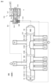
- FIG. 1 is a refrigerant circuit diagram of a refrigeration cycle device according to Embodiment 1.
- FIG. FIG. 4 is a diagram showing a refrigerant circuit and refrigerant flow during heating operation of the refrigeration cycle apparatus according to Embodiment 1;
- FIG. 10 is a diagram showing the arrangement of various sensors when using a refrigerant with no temperature gradient;
- FIG. 4 is a ph diagram showing changes in refrigerant state when a refrigerant without a temperature gradient is used;
- FIG. 4 is a diagram for explaining a process of deriving the inlet pressure of the first expansion valve 30;
- FIG. 4 is a diagram showing the arrangement of various sensors when using a non-azeotropic refrigerant;
- FIG. 4 is a ph diagram showing changes in refrigerant state when a non-azeotropic refrigerant is used;
- 4 is a flowchart for explaining control of the second expansion valve 72 when using a non-azeotropic refrigerant.
- FIG. 10 is a diagram showing a refrigerant circuit and refrigerant flow during cooling operation of the refrigeration cycle apparatus according to Embodiment 2;
- FIG. 10 is a diagram showing a refrigerant circuit and refrigerant flow during cooling operation of the refrigeration cycle apparatus according to Embodiment 2;
- FIG. 10 is a diagram showing a refrigerant circuit and refrigerant flow during cooling operation of the refrigeration cycle apparatus according to Embodiment 2;
- FIG. 10 is a diagram showing a refrigerant circuit and refrigerant flow during heating operation of the refrigeration cycle apparatus according to Embodiment 2;
- FIG. 11 is a diagram showing a refrigerant circuit and refrigerant flow during cooling operation of the refrigeration cycle apparatus according to Embodiment 3;
- FIG. 10 is a diagram showing a refrigerant circuit and refrigerant flow during heating operation of the refrigeration cycle apparatus according to Embodiment 3;
- FIG. 11 is a diagram showing a refrigerant circuit and a flow of refrigerant during cooling operation of the refrigeration cycle apparatus according to Embodiment 4;
- FIG. 11 is a diagram showing a refrigerant circuit and refrigerant flow during heating operation of the refrigeration cycle apparatus according to Embodiment 4;
- FIG. 12 is a diagram showing a refrigerant circuit and refrigerant flow during cooling operation of the refrigeration cycle apparatus according to Embodiment 5;
- FIG. 11 is a diagram showing the state of an eight-way valve 50B during cooling operation and the flow of refrigerant in Embodiment 5;
- FIG. 11 is a diagram showing a refrigerant circuit and refrigerant flow during heating operation of the refrigeration cycle apparatus according to Embodiment 5;
- FIG. 11 is a diagram showing the state of an eight-way valve 50B during heating operation and the flow of refrigerant in Embodiment 5;
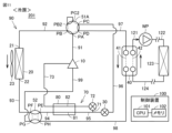
- FIG. 1 is a refrigerant circuit diagram of a refrigeration cycle device according to Embodiment 1.
- FIG. 1 shows the refrigerant circuit and refrigerant flow during cooling operation. The defrosting operation performed during the heating operation is also the same as in FIG.
- the refrigeration cycle device 1 includes a compressor 10, a first heat exchanger 20, a second heat exchanger 40, a third heat exchanger 80, a first expansion valve 30, a second expansion valve 72, a flow and a path switching device 50 .
- the compressor 10, the first heat exchanger 20, the second heat exchanger 40, the first expansion valve 30, and the pipes 91 to 99 constitute a refrigerant circuit 90 for circulating the refrigerant.
- the first heat exchanger 20 is configured to exchange heat between the outside air blown by the fan 23 and the refrigerant.
- the second heat exchanger 40 is configured to perform heat exchange between the heat medium and the refrigerant circulating in the utilization side circuit.
- the second heat exchanger 40 is, for example, a plate heat exchanger.
- the usage-side circuit includes a pump WP, a usage-side heat exchanger 123, and pipes 121, 122, and 124.
- the heat medium circulating in the utilization side circuit is, for example, water or brine.
- the user-side heat exchanger 123 is, for example, a water heater, an air conditioner, or the like.
- the second heat exchanger 40 has a channel 41 and a channel 42 .
- the second heat exchanger 40 is configured to exchange heat between the refrigerant flowing through the flow path 41 and the heat medium flowing through the flow path 42 .
- the injection flow path 70 includes pipes 71 and 73 and a second expansion valve 72 .
- the injection passage 70 reduces the pressure of the refrigerant before passing through the first expansion valve 30 in the refrigerant circuit 90 and returns it to the compressor 10 .
- the third heat exchanger 80 includes a first flow path 81 and a second flow path 82, each through which the refrigerant flows. Third heat exchanger 80 is configured to cause heat exchange between the refrigerant passing through first flow path 81 and the refrigerant passing through second flow path 82 .
- the first flow path 81 is arranged to flow the refrigerant toward the first expansion valve 30 in the refrigerant circuit 90
- the second flow path 82 is arranged to flow the refrigerant that has passed through the second expansion valve 72 back to the compressor 10 . placed in
- the flow switching device 50 connects the discharge port of the compressor 10 to the refrigerant inlet 21 of the first heat exchanger 20 in the first operation mode (cooling) shown in FIG.
- the outlet is connected to the refrigerant inlet of the first flow path 81
- the refrigerant outlet of the first expansion valve 30 is connected to the refrigerant inlet of the second heat exchanger 40
- the refrigerant outlet of the second heat exchanger 40 is connected to the compressor 10. configured to connect to an inhalation port;
- the first operation mode may be a defrosting operation during heating as well as cooling.
- Embodiment 1 an example in which the flow path switching device 50 includes a first four-way valve 51 and a second four-way valve 52 is shown.
- the first four-way valve 51 has ports PA, PB, PC, and PD.
- the second four-way valve 52 has ports PE, PF, PG and PH.
- a pipe 91 connects the discharge port of the compressor 10 and the port PA.
- a pipe 92 connects the port PB and the refrigerant inlet 21 of the first heat exchanger 20 .
- a pipe 93 connects the refrigerant outlet 22 of the first heat exchanger 20 and the port PF.
- a pipe 94 connects the port PE and the refrigerant inlet of the first flow path 81 .
- a pipe 95 connects the refrigerant outlet of the first flow path 81 and the refrigerant inlet of the first expansion valve 30 .
- a pipe 96 connects the refrigerant outlet of the first expansion valve 30 and the port PC.
- a pipe 97 connects the port PD and the refrigerant inlet of the second heat exchanger 40 .
- a pipe 98 connects the refrigerant outlet of the second heat exchanger 40 and the port PH.
- a pipe 99 connects the port PG and the suction port of the compressor 10 .
- the pipe 71 branches off from the pipe 95 and connects the pipe 95 and the refrigerant inlet of the second flow path 82 .
- a second expansion valve 72 is arranged in the middle of the pipe 71 .
- a pipe 73 connects the refrigerant outlet of the second flow path 82 and the intermediate pressure port of the compressor 10 .
- the refrigeration cycle device 1 further includes a control device 100 that controls the channel switching device 50 .
- the control device 100 includes a CPU (Central Processing Unit) 101, a memory 102 (ROM (Read Only Memory) and RAM (Random Access Memory)), an input/output buffer (not shown), and the like.
- the CPU 101 develops a program stored in the ROM into a RAM or the like and executes it.
- the program stored in the ROM is a program in which processing procedures of the control device 100 are described.
- the control device 100 controls each device in the refrigeration cycle apparatus 1 according to these programs. This control is not limited to processing by software, and processing by dedicated hardware (electronic circuit) is also possible.
- the first four-way valve 51 In the first operation mode (cooling), as indicated by the solid line in FIG. 1, the first four-way valve 51 is set so that the port PA and the port PB are in communication, and the port PC and the port PD are in communication. .
- the port PA and the port PD of the first four-way valve 51 are out of communication, and the port PB and the port PC are out of communication. That is, in the first operation mode (cooling), the first four-way valve 51 connects the discharge port of the compressor 10 to the refrigerant inlet 21 of the first heat exchanger 20 and connects the refrigerant outlet of the first expansion valve 30 to the second It is configured to connect to the refrigerant inlet of the heat exchanger 40 .
- the second four-way valve 52 In the first operation mode (cooling), as indicated by the solid line in FIG. 1, the second four-way valve 52 is set so that the port PE and the port PF are in communication, and the port PG and the port PH are in communication. .
- the port PE and the port PH of the second four-way valve 52 are out of communication, and the port PF and the port PG are out of communication. That is, the second four-way valve 52 connects the refrigerant outlet of the first heat exchanger 20 to the refrigerant inlet of the first flow path 81 and connects the refrigerant outlet of the second heat exchanger 40 in the first operation mode (cooling). It is configured to connect to the suction port of the compressor 10 .
- FIG. 2 is a diagram showing the refrigerant circuit and refrigerant flow during heating operation of the refrigeration cycle apparatus according to the first embodiment.
- the flow switching device 50 connects the discharge port of the compressor 10 to the refrigerant inlet of the second heat exchanger 40 and connects the refrigerant outlet of the second heat exchanger 40 to the first flow path.
- the refrigerant outlet of the first expansion valve 30 is connected to the refrigerant inlet 21 of the first heat exchanger 20, and the refrigerant outlet 22 of the first heat exchanger 20 is connected to the suction port of the compressor 10.
- the second operation mode may be a heating operation in which cold water is heated by the hot water supply device as well as the heating operation.
- the first four-way valve 51 is set so that the port PA and the port PD communicate, and the port PC and the port PB communicate.
- the first four-way valve 51 is out of communication between the port PA and the port PB, and out of communication between the port PC and the port PD. That is, in the second operation mode (heating), the first four-way valve 51 connects the discharge port of the compressor 10 to the refrigerant inlet of the second heat exchanger 40 and connects the refrigerant outlet of the first expansion valve 30 to the first heat exchanger. It is configured to connect to the refrigerant inlet of the exchanger 20 .
- the second four-way valve 52 In the second operation mode (heating), the second four-way valve 52 is set so that the port PE and the port PH communicate, and the port PG and the port PF communicate.
- the port PE and the port PF of the second four-way valve 52 are out of communication, and the port PG and the port PH are out of communication. That is, the second four-way valve 52 connects the refrigerant outlet of the second heat exchanger 40 to the refrigerant inlet of the first flow path 81 and connects the refrigerant outlet of the first heat exchanger 20 in the second operation mode (heating). It is configured to connect to the suction port of the compressor 10 .
- heat exchangers have a higher heat exchange efficiency when the heat medium that exchanges heat is in a counterflow relationship than in a parallel flow relationship.
- a heat exchanger in which the direction of refrigerant flow is reversed between cooling and heating if a counterflow relationship is established during cooling, a parallel flow relationship is established during heating. tends to get worse.
- the direction of refrigerant flow can be the same in both the first operation mode (cooling) and the second operation mode (heating).
- each heat exchanger can realize a counterflow relationship, so it is possible to improve the heat exchange efficiency in the two operation modes.
- the pipe 95 is on the refrigerant inlet side of the first expansion valve 30 and the second expansion valve 72, the dryness of the refrigerant in the pipe 95 is controlled to be kept close to the liquid phase. By doing so, the pressure regulating performance of the first expansion valve 30 and the second expansion valve 72 can be satisfactorily exhibited.
- the control device 100 calculates the dryness of the refrigerant in the pipe 95, which is the inlet side of the first expansion valve 30 and the second expansion valve 72, and controls the second expansion valve 72 so that the dryness reaches the target value. If the dryness of the refrigerant in the pipe 95 rises too much, vapor-phase refrigerant will be mixed into the inlets of the first expansion valve 30 and the second expansion valve 72, degrading the pressure regulation performance of the expansion valves. Therefore, when the dryness rises too much, the control device 100 controls the degree of opening of the second expansion valve 72 so that the dryness drops.
- FIG. 3 is a diagram showing the arrangement of various sensors when using a refrigerant with no Temperature Gradient.
- the control device 100 controls the degree of opening of the second expansion valve 72 based on the outputs of various sensors shown in FIG.
- the refrigeration cycle device 1 includes pressure sensors 110 and 116 , temperature sensors 111 , 112 , 114 , 115 and 117 and a flow rate sensor 113 .
- the pressure sensor 110 detects the discharge pressure Pd [MPa] of the compressor 10 .
- a pressure sensor 116 detects the suction pressure P s [MPa] of the compressor 10 .
- the temperature sensor 112 detects the refrigerant inlet temperature T e,in [° C.] of the second heat exchanger 40 .
- a temperature sensor 117 detects the refrigerant suction temperature T s [° C.] of the compressor 10 .
- a temperature sensor 115 detects the inlet water temperature T w,in [° C.] of the second heat exchanger 40 .
- a temperature sensor 114 detects the outlet water temperature T w,out [° C.] of the second heat exchanger 40 .
- the flow rate sensor 113 detects the water flow rate V w [L/min] of the second heat exchanger 40 .
- FIG. 4 is a ph diagram showing changes in the refrigerant state when using a refrigerant with no temperature gradient.
- Refrigerant discharged from the compressor 10 advances through the refrigerant circuit 90 and changes state in order of states A, B, C, D, and E.
- the refrigerant branched from the outlet of the first flow path 81 of the refrigerant circuit 90 advances through the injection flow path 70 and changes state in the order of states C, F, and G.
- FIG. Locations in FIG. 3 corresponding to states AG, respectively, are labeled with the same reference numerals AE.
- Refrigerant in state K is further compressed by compressor 10 to state A.
- the target dryness X tgt is set so that the state C does not deviate too much from the liquidus line, and the controller 100 controls the second expansion valve 72 so as to achieve the target dryness X tgt . to control the opening of the
- FIG. 5 is a flowchart for explaining the control of the second expansion valve 72 when using a refrigerant with no temperature gradient.
- Cv main [mm 2 ] indicates the Cv value of the expansion valve 30 .
- C p,w [kJ/(kg ⁇ K)] indicates the specific heat of water.
- F comp [Hz] indicates the operating frequency of the compressor 10 .
- Gr s [kg/h] indicates the amount of refrigerant circulating through the suction port of the compressor 10 .
- P d [MPa] indicates the pressure of the refrigerant discharged from the compressor 10 .
- P s [MPa] indicates the pressure of the refrigerant drawn into the compressor 10 .
- T e,in [°C] indicates the refrigerant temperature at the inlet of the evaporator.
- T s [° C.] indicates the temperature of the refrigerant drawn into the compressor 10 .
- T w,in [° C.] indicates the inlet water temperature of the heat exchanger 40 .
- T w,out [° C.] indicates the outlet water temperature of the heat exchanger 40 .
- V w [L/min] indicates the water flow rate of the heat exchanger 40 .
- V st [cc] indicates the stroke volume of the compressor 10 .
- ⁇ v [ ⁇ ] indicates the volumetric efficiency of the compressor 10 .
- ⁇ LEV,in [kg/m 3 ] indicates the refrigerant density at the inlet of the expansion valve 30 .
- ⁇ s [kg/m 3 ] represents the refrigerant suction density of the compressor 10 .
- hs denotes the enthalpy at the suction port of the compressor 10;
- fx(A, B) indicates a function that takes A and B as inputs and outputs x, and this function is mapped in advance.
- step S1 the control device 100 calculates the cooling capacity Qe by the following formula (1).
- Qe Vw ⁇ Cp ,w (Tw ,in -Tw ,out ) (1)
- step S2 the control device 100 calculates the refrigerant circulation amount Grs on the low pressure side by the following equation (2).
- Grs Fcomp.Vst.f ⁇ s ( Ps , Ts ) . ⁇ v (2 )
- step S3 the control device 100 calculates the evaporator inlet enthalpy he,in and the evaporator inlet pressure Pe, in by the following equations (3) and (4).
- step S4 the control device 100 calculates the pressure P LEV,in of the refrigerant at the inlet of the expansion valve 30 by the following equations (5) and (6). Calculate the dryness X LEV,in .
- step S5 the control device 100 calculates the target dryness Xtgt of the refrigerant at the inlet portion of the expansion valve 30 by the following equation (7).
- Xtgt fXtgt ( Pd , Ps , Fcomp) (7)
- step S6 the control device 100 compares the target dryness X tgt with the calculated current dryness X LEV,in . If the dryness X LEV,in is equal to or lower than the target dryness X tgt (YES in S6), in step S7, control device 100 reduces the opening of second expansion valve 72 arranged in injection passage 70.
- control device 100 adjusts the opening of second expansion valve 72 arranged in injection passage 70 to increase.
- the controller 100 prevents the dryness X LEV,in of the refrigerant flowing from the first flow path 81 of the third heat exchanger 80 into the first expansion valve 30 from increasing beyond the target dryness X tgt .
- the opening degree of the second expansion valve 72 is controlled as follows.
- FIG. 6 is a diagram for explaining symbols of various parameters of the first expansion valve 30.
- the first expansion valve 30 comprises a pulse motor stator coil 31 and rotor 32 , a screw 33 and a needle 34 . Needle 34 is inserted into orifice 35 by screw 33 to a varying extent as rotor 32 rotates. Thereby, the expansion valve 30 can change the degree of opening.
- P LEV,in , h LEV,in , and ⁇ LEV,in indicate the refrigerant pressure, enthalpy, and refrigerant density at the inlet of the first expansion valve 30, respectively.
- Cv main [mm 2 ] indicates the Cv value of the expansion valve 30
- Gr s [kg/h] indicates the refrigerant circulation amount of the suction port of the compressor 10
- h LEV,in [kJ/kg] is The enthalpy of the refrigerant at the inlet of the expansion valve 30 is indicated
- P e,in [MPa] indicates the pressure of the refrigerant at the inlet of the expansion valve 30 .
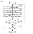
- FIG. 7 is a diagram for explaining the process of deriving the inlet pressure of the first expansion valve 30.
- the control device 100 sets an assumed value P LEV,in1 of the inlet pressure of the first expansion valve 30 .
- the control device 100 calculates the refrigerant density ⁇ LEV,in at the inlet portion of the expansion valve 30 by applying the assumed value P LEV,in1 to the following equation (8).
- ⁇ LEV,in f(P LEV,in ,h LEV,in )
- the control device 100 calculates the refrigerant pressure PLEV,in2 at the inlet portion of the expansion valve 30 by the following equation (9).
- step S14 the control device 100 compares the assumed value P LEV,in1 and the calculated refrigerant pressure P LEV,in2 to determine whether they are equal.
- step S11 If the convergence condition is not satisfied (NO in S14), return to step S11 and reset the assumed value.
- Newton's method, bisection method, and the like which are generally used for convergence calculation, may be used to reset the hypothetical values.
- FIG. 8 is a diagram showing the arrangement of various sensors when using a non-azeotropic refrigerant. Comparing FIG. 3 and FIG. 8, the refrigerating cycle apparatus 1 is common in that it includes pressure sensors 110 and 116 . 8, the temperature sensor 111 and the pressure sensor 118 are added, but the temperature sensors 112, 114, 115, 117 and the flow rate sensor 113 are not provided.
- FIG. 9 is a ph diagram showing changes in refrigerant state when a non-azeotropic refrigerant is used. Comparing FIG. 4 and FIG. 9, temperature variations are seen in the condensation steps AC, since in the case of FIG. 9 the isotherm TL is not parallel to the horizontal axis in the two-phase region. When the dryness X increases, the point C shifts toward the point A, so the temperature T_LEV ,in also increases. Therefore, when using a non-azeotropic refrigerant that exhibits a temperature gradient in the two-phase region, it is possible to calculate the dryness X LEV,in from the pressure P LEV,in and the temperature T LEV,in even in the two-phase region. It is understood that
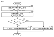
- FIG. 10 is a flowchart for explaining control of the second expansion valve 72 when using a non-azeotropic refrigerant.
- step S21 the control device 100 calculates the dryness XLEV,in of the refrigerant at the inlet portion of the expansion valve 30 by the following equation (10).
- XLEV,in fXLEV,in ( PLEV,in , TLEV,in ) (10)
- step S22 the control device 100 calculates the target dryness X tgt of the refrigerant at the inlet portion of the expansion valve 30 by the following equation (11).
- Xtgt fXtgt ( Pd , Ps , Fcomp ) (11)
- control device 100 changes the degree of opening of second expansion valve 72 so that X LEV,in becomes equal to X tgt .
- step S23 the control device 100 compares the target dryness X tgt with the calculated current dryness X LEV,in . If the dryness X LEV,in is equal to or less than the target dryness X tgt (YES in S23), in step S24, control device 100 reduces the opening of second expansion valve 72 arranged in injection passage 70. Let On the other hand, if the dryness X LEV,in is not equal to or lower than the target dryness X tgt (NO in S23), in step S25, control device 100 adjusts the opening of second expansion valve 72 arranged in injection passage 70 to increase.
- the degree of opening of the second expansion valve 72 is controlled so that the dryness X LEV,in matches the target dryness X tgt .
- the refrigeration cycle device of the present embodiment is suitably used for heat pump machines mainly for heating, such as water heaters and circulation heaters.
- Heat pump machines such as water heaters and circulating heaters, which are mainly used for heating, generally contain the amount of refrigerant required for heating operation, and the refrigerant amount tends to be insufficient during cooling operation. This is because during cooling operation, the air heat exchanger, which has a larger volume than the load side heat exchanger, becomes the condenser (high pressure), and the amount of refrigerant required to fill the condenser outlet with liquid refrigerant increases. be.
- the refrigerant at the inlet of the expansion valve becomes two-phase, and the refrigerant density decreases, causing a decrease in the low-pressure side pressure due to insufficient opening of the expansion valve.
- the low pressure drops, freezing occurs in the load-side heat exchanger, and if the load-side heat exchanger is damaged, it may burst and leak refrigerant.
- the refrigerant and heat medium air, water, refrigerant, etc.
- the refrigerant and heat medium are arranged in counterflow in the heat exchanger during heating operation. be done. Therefore, during the cooling operation and the defrosting operation, the direction of refrigerant flow in the heat exchanger is reversed, resulting in a parallel flow, which degrades the performance.
- the refrigerant inflow direction of the three heat exchangers can be unified in the counterflow direction, so compared to the conventional refrigeration cycle equipment in which parallel flows coexist. performance improvement can be expected.
- the internal heat exchange using the third heat exchanger 80 and the second expansion valve 72 arranged in the injection flow path 70 are used as the refrigerant at the outlet of the condenser. Since it can be used, it can be expected to improve the performance of the refrigeration cycle device by injecting the refrigerant.
- the dryness XLEV,in of the refrigerant on the inlet side of the first expansion valve 30 can be lowered, the refrigerant density at the inlet of the first expansion valve 30 increases and the pressure drop of the refrigerant sucked into the compressor 10 is suppressed. can.
- FIG. 11 is a diagram showing a refrigerant circuit and refrigerant flow during cooling operation of the refrigeration cycle apparatus according to the second embodiment.
- a flow path switching device 50 of a refrigeration cycle device 201 shown in FIG. 11 includes a six-way valve 51A and a four-way valve 52 .
- the hexagonal valve 51A has a port PB2 and a port PC2 in addition to the ports PA to PD. Ports PA to PD are connected to respective pipes of the refrigerant circuit in the same manner as in FIG. The port PB2 and the port PC2 are connected by piping outside the hexagonal valve 51A.
- 6-way valve 51A can be used for switching connections in the same way as the 4-way valve 51 shown in FIG.
- 6-way valves have also been produced, and if 6-way valves can be used instead of 4-way valves, there are cases where it is convenient in terms of stock adjustment of raw materials.
- the refrigeration cycle device 201 shown in FIG. 11 has the same configuration as the refrigeration cycle device 1 shown in FIG. 1, so description thereof will not be repeated here.
- the hexagonal valve 51A connects the discharge port of the compressor 10 to the refrigerant inlet 21 of the first heat exchanger 20 and connects the refrigerant outlet of the first expansion valve 30 to the second heat exchanger 40 in the first operation mode (cooling). is configured to connect to the refrigerant inlet of the At this time, inside the hexagonal valve 51A, flow paths are formed so that the port PA and the port PB communicate, the port PC and the port PD communicate, and the port PB2 and the port PC2 communicate.
- the four-way valve 52 connects the refrigerant outlet 22 of the first heat exchanger 20 to the refrigerant inlet of the first flow path 81 and connects the refrigerant outlet of the second heat exchanger 40 to the compressor 10 in the first operation mode (cooling). configured to connect to the inhalation port of the
- FIG. 12 is a diagram showing the refrigerant circuit and refrigerant flow during heating operation of the refrigeration cycle apparatus according to the second embodiment.
- the hexagonal valve 51A connects the discharge port of the compressor 10 to the refrigerant inlet of the second heat exchanger 40 and connects the refrigerant outlet of the first expansion valve 30 to the first heat exchanger 20 in the second operation mode (heating). It is configured to connect to the coolant inlet 21 .
- flow passages are formed inside the hexagonal valve 51A such that the port PA and the port PD are in communication, the port PB and the port PB2 are in communication, and the port PC2 and the port PC are in communication.
- the port PB and the port PC come to communicate with each other through the external piping.
- the four-way valve 52 connects the refrigerant outlet of the second heat exchanger 40 to the refrigerant inlet of the first flow path 81 and connects the refrigerant outlet 22 of the first heat exchanger 20 to the compressor 10 in the second operation mode (heating). configured to connect to the inhalation port of the
- Embodiment 2 With the refrigeration cycle apparatus 201 of Embodiment 2 configured as described above, the same effects as those of Embodiment 1 can be obtained.
- FIG. 13 is a diagram showing the refrigerant circuit and refrigerant flow during cooling operation of the refrigeration cycle apparatus according to the third embodiment.
- a flow path switching device 50 of a refrigeration cycle device 202 shown in FIG. 13 includes a four-way valve 51 and a six-way valve 52A.
- the hexagonal valve 52A has a port PG2 and a port PH2 in addition to the ports PE to PH. Ports PE to PH are connected to respective pipes of the refrigerant circuit in the same manner as in FIG. The port PG2 and the port PH2 are connected by piping outside the hexagonal valve 52A.
- the 6-way valve 52A can be used for switching connections in the same manner as the 4-way valve 52 shown in FIG.
- the four-way valve connects the discharge port of the compressor 10 to the refrigerant inlet 21 of the first heat exchanger 20 and connects the refrigerant outlet of the first expansion valve 30 to the second heat exchanger 40 in the first operation mode (cooling). configured to connect to a refrigerant inlet;
- the hexagonal valve 52A connects the refrigerant outlet 22 of the first heat exchanger 20 to the refrigerant inlet of the first flow path 81 and connects the refrigerant outlet of the second heat exchanger 40 to the compressor 10 in the first operation mode (cooling). configured to connect to the inhalation port of the At this time, flow passages are formed inside the hexagonal valve 52A such that the port PE and the port PF are in communication, the port PG and the port PG2 are in communication, and the port PH2 and the port PH are in communication. As a result, the port PG and the port PH are communicated through the external pipe.
- FIG. 14 is a diagram showing the refrigerant circuit and refrigerant flow during heating operation of the refrigeration cycle apparatus according to the third embodiment.
- the four-way valve 51 connects the discharge port of the compressor 10 to the refrigerant inlet of the second heat exchanger 40 and connects the refrigerant outlet of the first expansion valve 30 to the first heat exchanger 20 in the second operation mode (heating). It is configured to connect to the coolant inlet 21 .
- the hexagonal valve 52A connects the refrigerant outlet of the second heat exchanger 40 to the refrigerant inlet of the first flow path 81 and connects the refrigerant outlet 22 of the first heat exchanger 20 to the compressor 10 in the second operation mode (heating). configured to connect to the inhalation port of the At this time, flow passages are formed inside the hexagonal valve 52A so that the port PG and the port PF communicate, the port PE and the port PH communicate, and the port PG2 and the port PH2 communicate.
- FIG. 15 is a diagram showing a refrigerant circuit and refrigerant flow during cooling operation of the refrigeration cycle apparatus according to the fourth embodiment.
- a flow switching device 50 of a refrigeration cycle device 203 shown in FIG. 15 includes a first hexagonal valve 51A and a second hexagonal valve 52A.
- the connection of the first hexagonal valve 51A is the same as in the second embodiment, and the connection of the second hexagonal valve 52A is the same as in the third embodiment, so the description will not be repeated here.
- the first hexagonal valve 51A connects the discharge port of the compressor 10 to the refrigerant inlet 21 of the first heat exchanger 20 and connects the refrigerant outlet of the first expansion valve 30 to the second heat exchange mode in the first operation mode (cooling). configured to connect to the coolant inlet of vessel 40 .
- the second hexagonal valve 52A connects the refrigerant outlet 22 of the first heat exchanger 20 to the refrigerant inlet of the first flow path 81 and compresses the refrigerant outlet of the second heat exchanger 40 in the first operation mode (cooling). configured to connect to the intake port of aircraft 10;
- FIG. 16 is a diagram showing the refrigerant circuit and refrigerant flow during heating operation of the refrigeration cycle apparatus according to the fourth embodiment.
- the first hexagonal valve 51A connects the discharge port of the compressor 10 to the refrigerant inlet of the second heat exchanger 40, and connects the refrigerant outlet of the first expansion valve 30 to the first heat exchanger. It is configured to connect to the coolant inlet 21 of 20 .
- the second hexagonal valve 52A connects the refrigerant outlet of the second heat exchanger 40 to the refrigerant inlet of the first flow path 81 and compresses the refrigerant outlet 22 of the first heat exchanger 20 in the second operation mode (heating). configured to connect to the intake port of aircraft 10;
- the flow path switching device 50 of the refrigeration cycle device 204 of Embodiment 5 includes an eight-way valve 50B.
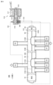
- FIG. 17 is a diagram showing the refrigerant circuit and refrigerant flow during cooling operation of the refrigeration cycle apparatus according to the fifth embodiment.
- FIG. 18 is a diagram showing the state of the eight-way valve 50B during cooling operation and the flow of the refrigerant according to the fifth embodiment.
- the eight-way valve 50B includes a tubular valve body 308. Ports PA and PE are formed on one side of the valve body 308 in the circumferential direction, and ports PB, PC, PD, PF, PG and PH are formed on the other side.
- connection destinations of ports PA to PH are the same as in FIG. 1, so the description will not be repeated.
- a piston 312 in which three sliding pressure receiving bodies 310A, 310B, and 310C are connected to a connecting rod 311 is provided in the valve body 308 of the eight-way valve 50B.
- Slide valve bodies 313 A and 313 B are fixed to the connecting rod 311 .
- the slide valve body 313A slides on the valve seat provided with the ports PB, PC and PD, and the slide valve body 313B slides on the valve seat provided with the ports PF, PG and PH. do.
- the piston 312 partitions the first chamber R1, the second chamber R2, the third chamber R3 and the fourth chamber R4.
- the eight-way valve 50B further includes a pilot solenoid valve 514 for switching the slide valve body. Pilot solenoid valve 514 includes valve body 516 coupled to plunger 515 , solenoid coil 517 and coil spring 518 .
- the slide valve body 313A is formed with two communication lumens for communicating two adjacent ports at the ports PB, PC, and PD. In the state shown in FIG. , PD, and the port PA communicates with the port PB via the second chamber R2.
- the slide valve body 313B is formed with two communicating lumens for communicating two adjacent ports at the ports PF, PG, and PH.
- PH In the state shown in FIG. , PH, and the port PE communicates with the port PF via the third chamber R3.
- the eight-way valve 50B is in the cooling operation position where the refrigerant circulates along the solid line path in FIG.
- FIG. 19 is a diagram showing the refrigerant circuit and refrigerant flow during heating operation of the refrigeration cycle apparatus according to the fifth embodiment.
- FIG. 20 is a diagram showing the state of the eight-way valve 50B during heating operation and the flow of the refrigerant according to the fifth embodiment.
- valve body 516 biased by the coil spring 518 connects the low-pressure communication pipe 519 to the conduit 520 for the first chamber R1 and connects the high-pressure introduction pipe 521 to the conduit 522 for the fourth chamber R4. Therefore, a high pressure is introduced into the fourth chamber R4 to move the piston 312 and the slide valve bodies 313A and 313B toward the first chamber R1.
- the communicating lumen of the slide valve body 313A communicates with the ports PB and PC, and the port PA communicates with the port PD via the second chamber R2.
- the communication lumen of the slide valve body 313B communicates the ports PF and PG, and the port PE communicates with the port PH via the third chamber R3.
- the eight-way valve 50B is in the heating operation position where the refrigerant circulates along the path indicated by the solid line in FIG.
- the refrigeration cycle apparatus according to Embodiment 5 can achieve effects similar to those of Embodiments 1 to 4, and can reduce the number of parts and the number of board ports used.
- the refrigeration cycle device 1 shown in FIG. 1 includes a compressor 10, a first heat exchanger 20, a second heat exchanger 40, a third heat exchanger 80, a first expansion valve 30, and a second expansion valve. 72 and a channel switching device 50 .
- the compressor 10, the first heat exchanger 20, the second heat exchanger 40, and the first expansion valve 30 constitute a refrigerant circuit 90 that circulates the refrigerant.
- the second expansion valve 72 constitutes a part of the injection flow path 70 that reduces the pressure of the refrigerant before passing through the first expansion valve 30 in the refrigerant circuit 90 and returns it to the compressor 10 .
- the third heat exchanger 80 includes a first flow path 81 through which the refrigerant flows, and a second flow path 82 through which the refrigerant flows. Third heat exchanger 80 is configured to cause heat exchange between the refrigerant passing through first flow path 81 and the refrigerant passing through second flow path 82 .
- the first flow path 81 is arranged to flow the refrigerant toward the first expansion valve 30 in the refrigerant circuit 90 .
- the second flow path 82 is arranged to return refrigerant that has passed through the second expansion valve 72 back to the compressor 10 .
- the flow switching device 50 connects the discharge port of the compressor 10 to the refrigerant inlet of the first heat exchanger 20, and connects the refrigerant outlet of the first heat exchanger 20 to the first flow path.
- the refrigerant outlet of the first expansion valve 30 is connected to the refrigerant inlet of the second heat exchanger 40, and the refrigerant outlet of the second heat exchanger 40 is connected to the suction port of the compressor 10. configured to
- the flow switching device 50 connects the discharge port of the compressor 10 to the refrigerant inlet of the second heat exchanger 40 and connects the refrigerant outlet of the second heat exchanger 40 to the first flow path.
- the refrigerant outlet of the first expansion valve 30 is connected to the refrigerant inlet of the first heat exchanger 20
- the refrigerant outlet of the first heat exchanger 20 is connected to the suction port of the compressor 10. configured to
- the first heat exchanger 20, the second heat exchanger 40, the third heat exchanger 80, the first expansion valve 30, and the second expansion valve 72 are used in any of the first operation mode and the second operation mode.
- the direction in which the refrigerant flows in each of the is the same.
- the heat medium exchanging heat is in a countercurrent relationship. configured to exchange heat.
- the heat medium that exchanges heat with the refrigerant is air in the first heat exchanger 20 , water or brine in the second heat exchanger 40 , and refrigerant in the third heat exchanger 80 .
- the channel switching device 50 includes a first four-way valve 51 and a second four-way valve 52, as shown in FIGS.
- the first four-way valve 51 connects the discharge port of the compressor 10 to the refrigerant inlet of the first heat exchanger 20 and connects the refrigerant outlet of the first expansion valve 30 to the second heat exchanger in the first operation mode (cooling). 40, and in the second operation mode (heating), the discharge port of the compressor 10 is connected to the refrigerant inlet of the second heat exchanger 40, and the refrigerant outlet of the first expansion valve 30 is connected to the first heat exchange configured to connect to the coolant inlet of vessel 20 .
- the second four-way valve 52 connects the refrigerant outlet of the first heat exchanger 20 to the refrigerant inlet of the first flow path 81 and connects the refrigerant outlet of the second heat exchanger 40 to the compressor in the first operation mode (cooling). 10, and in the second operation mode (heating), the refrigerant outlet of the second heat exchanger 40 is connected to the refrigerant inlet of the first flow path 81, and the first heat exchanger 20 It is configured to connect the refrigerant outlet to the suction port of the compressor 10 .
- the channel switching device 50 includes a six-way valve 51A and a four-way valve 52, as shown in FIGS.
- the hexagonal valve 51A connects the discharge port of the compressor 10 to the refrigerant inlet of the first heat exchanger 20 and connects the refrigerant outlet of the first expansion valve 30 to the second heat exchanger 40 in the first operation mode (cooling).
- the discharge port of the compressor 10 is connected to the refrigerant inlet of the second heat exchanger 40, and the refrigerant outlet of the first expansion valve 30 is connected to the first heat exchanger 20.
- the four-way valve 52 connects the refrigerant outlet of the first heat exchanger 20 to the refrigerant inlet of the first flow path 81 and connects the refrigerant outlet of the second heat exchanger 40 to the compressor 10 in the first operation mode (cooling). configured to connect to the suction port, and in the second mode of operation (heating), connect the refrigerant outlet of the second heat exchanger 40 to the refrigerant inlet of the first flow path 81 and the refrigerant outlet of the first heat exchanger 20; to the suction port of the compressor 10 .
- the channel switching device 50 includes a four-way valve 51 and a six-way valve 52A.
- the four-way valve 51 connects the discharge port of the compressor 10 to the refrigerant inlet of the first heat exchanger 20 and connects the refrigerant outlet of the first expansion valve 30 to the second heat exchanger 40 in the first operation mode (cooling).
- the discharge port of the compressor 10 is connected to the refrigerant inlet of the second heat exchanger 40, and the refrigerant outlet of the first expansion valve 30 is connected to the first heat exchanger 20.
- the hexagonal valve 52A connects the refrigerant outlet of the first heat exchanger 20 to the refrigerant inlet of the first flow path 81 and connects the refrigerant outlet of the second heat exchanger 40 to the compressor 10 in the first operation mode (cooling). configured to connect to the suction port, and in the second mode of operation (heating), connect the refrigerant outlet of the second heat exchanger 40 to the refrigerant inlet of the first flow path 81 and the refrigerant outlet of the first heat exchanger 20; to the suction port of the compressor 10 .
- the channel switching device includes a first 6-way valve 51A and a second 6-way valve 52A.
- the first hexagonal valve 51A connects the discharge port of the compressor 10 to the refrigerant inlet of the first heat exchanger 20, and connects the refrigerant outlet of the first expansion valve 30 to the second heat exchanger.
- the discharge port of the compressor 10 is connected to the refrigerant inlet of the second heat exchanger 40, and the refrigerant outlet of the first expansion valve 30 is connected to the first heat exchange configured to connect to the coolant inlet of vessel 20 .
- the second hexagonal valve 52A connects the refrigerant outlet of the first heat exchanger 20 to the refrigerant inlet of the first flow path 81, and connects the refrigerant outlet of the second heat exchanger 40 to the compressor.
- the refrigerant outlet of the second heat exchanger 40 is connected to the refrigerant inlet of the first flow path 81, and the first heat exchanger 20 It is configured to connect the refrigerant outlet to the suction port of the compressor 10 .
- the channel switching device 50 includes an eight-way valve 50B.
- the refrigeration cycle device further includes a control device 100 that controls the first expansion valve 30 and the second expansion valve 72.
- the control device 100 controls the opening degree of the second expansion valve 72 so that the dryness of the refrigerant flowing into the first expansion valve 30 from the first flow path 81 of the third heat exchanger 80 does not exceed the target dryness. do.
Landscapes
- Engineering & Computer Science (AREA)
- Physics & Mathematics (AREA)
- Mechanical Engineering (AREA)
- Thermal Sciences (AREA)
- General Engineering & Computer Science (AREA)
- Compression-Type Refrigeration Machines With Reversible Cycles (AREA)
Priority Applications (5)
| Application Number | Priority Date | Filing Date | Title |
|---|---|---|---|
| EP21962420.2A EP4425070A1 (en) | 2021-10-28 | 2021-10-28 | Refrigeration cycle apparatus |
| US18/697,230 US20250003645A1 (en) | 2021-10-28 | 2021-10-28 | Refrigeration cycle apparatus |
| CN202180103573.5A CN118140102A (zh) | 2021-10-28 | 2021-10-28 | 制冷循环装置 |
| PCT/JP2021/039845 WO2023073872A1 (ja) | 2021-10-28 | 2021-10-28 | 冷凍サイクル装置 |
| JP2023555985A JPWO2023073872A1 (https=) | 2021-10-28 | 2021-10-28 |
Applications Claiming Priority (1)
| Application Number | Priority Date | Filing Date | Title |
|---|---|---|---|
| PCT/JP2021/039845 WO2023073872A1 (ja) | 2021-10-28 | 2021-10-28 | 冷凍サイクル装置 |
Publications (1)
| Publication Number | Publication Date |
|---|---|
| WO2023073872A1 true WO2023073872A1 (ja) | 2023-05-04 |
Family
ID=86157562
Family Applications (1)
| Application Number | Title | Priority Date | Filing Date |
|---|---|---|---|
| PCT/JP2021/039845 Ceased WO2023073872A1 (ja) | 2021-10-28 | 2021-10-28 | 冷凍サイクル装置 |
Country Status (5)
| Country | Link |
|---|---|
| US (1) | US20250003645A1 (https=) |
| EP (1) | EP4425070A1 (https=) |
| JP (1) | JPWO2023073872A1 (https=) |
| CN (1) | CN118140102A (https=) |
| WO (1) | WO2023073872A1 (https=) |
Cited By (2)
| Publication number | Priority date | Publication date | Assignee | Title |
|---|---|---|---|---|
| WO2025141717A1 (ja) * | 2023-12-26 | 2025-07-03 | 三菱電機株式会社 | 冷凍サイクル装置 |
| JP7813078B1 (ja) * | 2025-09-04 | 2026-02-12 | 株式会社ミラプロ | 磁気冷凍装置 |
Citations (7)
| Publication number | Priority date | Publication date | Assignee | Title |
|---|---|---|---|---|
| JP2006071137A (ja) * | 2004-08-31 | 2006-03-16 | Daikin Ind Ltd | 冷凍装置 |
| JP2015010816A (ja) * | 2013-07-02 | 2015-01-19 | 三菱電機株式会社 | 冷媒回路および空気調和装置 |
| WO2017145219A1 (ja) * | 2016-02-22 | 2017-08-31 | 三菱電機株式会社 | 冷凍サイクル装置 |
| JP2019011899A (ja) * | 2017-06-30 | 2019-01-24 | 株式会社富士通ゼネラル | 空気調和装置 |
| JP2019086244A (ja) * | 2017-11-08 | 2019-06-06 | ダイキン工業株式会社 | 冷媒サイクル装置 |
| JP2020186909A (ja) | 2019-03-29 | 2020-11-19 | ダイキン工業株式会社 | 冷凍サイクル装置 |
| WO2021124458A1 (ja) * | 2019-12-17 | 2021-06-24 | 三菱電機株式会社 | 冷凍サイクル装置 |
Family Cites Families (2)
| Publication number | Priority date | Publication date | Assignee | Title |
|---|---|---|---|---|
| JP5409715B2 (ja) * | 2011-07-04 | 2014-02-05 | 三菱電機株式会社 | 空気調和装置 |
| JP7105580B2 (ja) * | 2018-02-20 | 2022-07-25 | 三菱電機株式会社 | 空気調和機 |
-
2021
- 2021-10-28 CN CN202180103573.5A patent/CN118140102A/zh active Pending
- 2021-10-28 US US18/697,230 patent/US20250003645A1/en active Pending
- 2021-10-28 EP EP21962420.2A patent/EP4425070A1/en not_active Withdrawn
- 2021-10-28 JP JP2023555985A patent/JPWO2023073872A1/ja not_active Withdrawn
- 2021-10-28 WO PCT/JP2021/039845 patent/WO2023073872A1/ja not_active Ceased
Patent Citations (7)
| Publication number | Priority date | Publication date | Assignee | Title |
|---|---|---|---|---|
| JP2006071137A (ja) * | 2004-08-31 | 2006-03-16 | Daikin Ind Ltd | 冷凍装置 |
| JP2015010816A (ja) * | 2013-07-02 | 2015-01-19 | 三菱電機株式会社 | 冷媒回路および空気調和装置 |
| WO2017145219A1 (ja) * | 2016-02-22 | 2017-08-31 | 三菱電機株式会社 | 冷凍サイクル装置 |
| JP2019011899A (ja) * | 2017-06-30 | 2019-01-24 | 株式会社富士通ゼネラル | 空気調和装置 |
| JP2019086244A (ja) * | 2017-11-08 | 2019-06-06 | ダイキン工業株式会社 | 冷媒サイクル装置 |
| JP2020186909A (ja) | 2019-03-29 | 2020-11-19 | ダイキン工業株式会社 | 冷凍サイクル装置 |
| WO2021124458A1 (ja) * | 2019-12-17 | 2021-06-24 | 三菱電機株式会社 | 冷凍サイクル装置 |
Cited By (2)
| Publication number | Priority date | Publication date | Assignee | Title |
|---|---|---|---|---|
| WO2025141717A1 (ja) * | 2023-12-26 | 2025-07-03 | 三菱電機株式会社 | 冷凍サイクル装置 |
| JP7813078B1 (ja) * | 2025-09-04 | 2026-02-12 | 株式会社ミラプロ | 磁気冷凍装置 |
Also Published As
| Publication number | Publication date |
|---|---|
| JPWO2023073872A1 (https=) | 2023-05-04 |
| EP4425070A1 (en) | 2024-09-04 |
| US20250003645A1 (en) | 2025-01-02 |
| CN118140102A (zh) | 2024-06-04 |
Similar Documents
| Publication | Publication Date | Title |
|---|---|---|
| CN103975202B (zh) | 空调装置 | |
| US9003823B2 (en) | Combined air-conditioning and hot-water supply system | |
| US8671706B2 (en) | Heat pump | |
| US8789382B2 (en) | Heat pump including at least two refrigerant injection flow paths into a scroll compressor | |
| US10036562B2 (en) | Air-conditioning apparatus | |
| KR101366986B1 (ko) | 히트 펌프 시스템 | |
| JP5968534B2 (ja) | 空気調和装置 | |
| USRE43998E1 (en) | Refrigeration/air conditioning equipment | |
| EP3133356B1 (en) | Refrigeration device | |
| JP5383816B2 (ja) | 空気調和装置 | |
| EP1780476A1 (en) | Hot-water supply device | |
| CN101809383A (zh) | 空调供热水复合系统 | |
| US9599378B2 (en) | Air-conditioning apparatus | |
| EP2829821B1 (en) | Heat pump | |
| CN113167517A (zh) | 空调装置 | |
| US9599380B2 (en) | Refrigerant charging method for air-conditioning apparatus and air-conditioning apparatus | |
| WO2023073872A1 (ja) | 冷凍サイクル装置 | |
| WO2022230034A1 (ja) | 空気調和装置 | |
| JP2023511677A (ja) | 空気調和装置 | |
| CN222799323U (zh) | 空调热泵系统 |
Legal Events
| Date | Code | Title | Description |
|---|---|---|---|
| 121 | Ep: the epo has been informed by wipo that ep was designated in this application |
Ref document number: 21962420 Country of ref document: EP Kind code of ref document: A1 |
|
| WWE | Wipo information: entry into national phase |
Ref document number: 18697230 Country of ref document: US |
|
| ENP | Entry into the national phase |
Ref document number: 2023555985 Country of ref document: JP Kind code of ref document: A |
|
| WWE | Wipo information: entry into national phase |
Ref document number: 202180103573.5 Country of ref document: CN |
|
| WWE | Wipo information: entry into national phase |
Ref document number: 2021962420 Country of ref document: EP |
|
| NENP | Non-entry into the national phase |
Ref country code: DE |
|
| ENP | Entry into the national phase |
Ref document number: 2021962420 Country of ref document: EP Effective date: 20240528 |