WO2023073797A1 - 発汗分析装置および方法 - Google Patents
発汗分析装置および方法 Download PDFInfo
- Publication number
- WO2023073797A1 WO2023073797A1 PCT/JP2021/039419 JP2021039419W WO2023073797A1 WO 2023073797 A1 WO2023073797 A1 WO 2023073797A1 JP 2021039419 W JP2021039419 W JP 2021039419W WO 2023073797 A1 WO2023073797 A1 WO 2023073797A1
- Authority
- WO
- WIPO (PCT)
- Prior art keywords
- perspiration
- power supply
- amount
- calculation unit
- wearable sensor
- Prior art date
- Legal status (The legal status is an assumption and is not a legal conclusion. Google has not performed a legal analysis and makes no representation as to the accuracy of the status listed.)
- Ceased
Links
Images
Classifications
-
- A—HUMAN NECESSITIES
- A61—MEDICAL OR VETERINARY SCIENCE; HYGIENE
- A61B—DIAGNOSIS; SURGERY; IDENTIFICATION
- A61B5/00—Measuring for diagnostic purposes; Identification of persons
- A61B5/145—Measuring characteristics of blood in vivo, e.g. gas concentration or pH-value ; Measuring characteristics of body fluids or tissues, e.g. interstitial fluid or cerebral tissue
- A61B5/14507—Measuring characteristics of blood in vivo, e.g. gas concentration or pH-value ; Measuring characteristics of body fluids or tissues, e.g. interstitial fluid or cerebral tissue specially adapted for measuring characteristics of body fluids other than blood
- A61B5/14517—Measuring characteristics of blood in vivo, e.g. gas concentration or pH-value ; Measuring characteristics of body fluids or tissues, e.g. interstitial fluid or cerebral tissue specially adapted for measuring characteristics of body fluids other than blood for sweat
-
- A—HUMAN NECESSITIES
- A61—MEDICAL OR VETERINARY SCIENCE; HYGIENE
- A61B—DIAGNOSIS; SURGERY; IDENTIFICATION
- A61B5/00—Measuring for diagnostic purposes; Identification of persons
-
- A—HUMAN NECESSITIES
- A61—MEDICAL OR VETERINARY SCIENCE; HYGIENE
- A61B—DIAGNOSIS; SURGERY; IDENTIFICATION
- A61B5/00—Measuring for diagnostic purposes; Identification of persons
- A61B5/145—Measuring characteristics of blood in vivo, e.g. gas concentration or pH-value ; Measuring characteristics of body fluids or tissues, e.g. interstitial fluid or cerebral tissue
- A61B5/14546—Measuring characteristics of blood in vivo, e.g. gas concentration or pH-value ; Measuring characteristics of body fluids or tissues, e.g. interstitial fluid or cerebral tissue for measuring analytes not otherwise provided for, e.g. ions, cytochromes
-
- A—HUMAN NECESSITIES
- A61—MEDICAL OR VETERINARY SCIENCE; HYGIENE
- A61B—DIAGNOSIS; SURGERY; IDENTIFICATION
- A61B5/00—Measuring for diagnostic purposes; Identification of persons
- A61B5/42—Detecting, measuring or recording for evaluating the gastrointestinal, the endocrine or the exocrine systems
- A61B5/4261—Evaluating exocrine secretion production
- A61B5/4266—Evaluating exocrine secretion production sweat secretion
-
- A—HUMAN NECESSITIES
- A61—MEDICAL OR VETERINARY SCIENCE; HYGIENE
- A61B—DIAGNOSIS; SURGERY; IDENTIFICATION
- A61B5/00—Measuring for diagnostic purposes; Identification of persons
- A61B5/68—Arrangements of detecting, measuring or recording means, e.g. sensors, in relation to patient
- A61B5/6801—Arrangements of detecting, measuring or recording means, e.g. sensors, in relation to patient specially adapted to be attached to or worn on the body surface
-
- A—HUMAN NECESSITIES
- A61—MEDICAL OR VETERINARY SCIENCE; HYGIENE
- A61B—DIAGNOSIS; SURGERY; IDENTIFICATION
- A61B2560/00—Constructional details of operational features of apparatus; Accessories for medical measuring apparatus
- A61B2560/02—Operational features
- A61B2560/0204—Operational features of power management
- A61B2560/0209—Operational features of power management adapted for power saving
Definitions
- the present invention relates to a perspiration analysis device and method that is worn on the human body and measures the amount of perspiration and electrolyte concentration in the wearer's sweat.
- Heatstroke refers to a state of multiple organ failure caused by increased metabolism due to high temperature environments and intense exercise.
- human body temperature is maintained at about 37° C. through a thermoregulatory process by the anterior hypothalamus.
- Several mechanisms associated with perspiration serve to cool the body surface.
- body temperature rises cutaneous vasodilation due to active sympathetic nerve activity increases blood flow in the skin, initiating thermal sweating. Cutaneous vasodilation causes a relative decrease in intravascular volume and contributes to thermal syncope. Loss of salt and water through sweat causes dehydration and salt depletion, accompanied by heat exhaustion and cramps.
- thermoregulatory function declines, followed by the outflow of blood from the central circulation to the skin and muscles, which reduces the blood flow to the internal organs, leading to organ failure, a condition known as heat stroke.
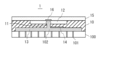
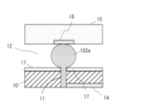
- FIG. 8 is a cross-sectional view of the wearable sensor disclosed in Patent Document 1
- FIG. 9 is an enlarged view of FIG.
- the wearable sensor 1 includes a substrate 10 having a through hole 11 serving as a liquid flow path and a concave portion 12 communicating with an outlet side end of the through hole 11, and a base having an inlet end of the through hole 11 open.
- an electrode 14 arranged on the surface of the material 10
- a water absorbing structure 15 arranged on the outlet side surface of the substrate 10 so as to be in contact with the liquid flowing out from the outlet side opening of the through hole 11 into the recess 12
- a surface of the water-absorbing structure 15 facing the base material 10 is provided with a water-absorbing electrode 16 disposed so as to face the outlet side opening of the through-hole 11 .
- the amount of perspiration of the wearer of the wearable sensor 1 and Electrolyte concentration can be calculated.
- the sweat droplet 102a contacts the electrode 16 current flows between the electrodes 14 and 16, and when the droplet 102a disappears, current stops flowing. As a result, the current continues to flow while the droplet 102a is present between the electrodes 14 and 16, resulting in an increase in power consumption.
- the present invention was made to solve the above problems, and aims to provide a perspiration analysis device and method that can measure the amount of perspiration and electrolyte concentration in sweat while saving power.
- a perspiration analyzer includes a wearable sensor configured to output an electrical signal derived from the amount of sweat secreted from the wearer's skin and an electrolyte concentration, and an electrical signal obtained by the wearable sensor. and a perspiration calculation unit configured to calculate the amount of perspiration of the wearer based on the electrical signal obtained by the wearable sensor. a power supply unit configured to supply power to the wearable sensor, the perspiration amount calculation unit, and the electrolyte concentration calculation unit; and from the power supply unit when a power supply stop condition is satisfied.
- Power supply to the wearable sensor, the perspiration amount calculation unit, and the electrolyte concentration calculation unit is stopped, and power supply to the wearable sensor, the perspiration amount calculation unit, and the electrolyte concentration calculation unit is terminated when the power supply stop period ends.
- a power supply control unit configured to restart supply, and a stop period calculation unit configured to calculate the power supply stop period based on the electrical signal obtained by the wearable sensor. It is something to do.
- the electrical signal is a current that changes due to intermittent droplets generated in the wearable sensor due to perspiration of the wearer
- the power control unit includes the It is characterized in that it is determined that the power supply stop condition is established when a predetermined time has elapsed from the time when the current started to change due to the droplet.
- the electrical signal is a current that changes due to intermittent droplets generated in the wearable sensor due to perspiration of the wearer
- the power control unit includes the It is characterized in that it is determined that the power supply stop condition is satisfied when the current peak occurs after power supply to the wearable sensor, the perspiration amount calculation unit, and the electrolyte concentration calculation unit is started.
- the electric signal is a current that changes due to intermittent droplets generated in the wearable sensor due to perspiration of the wearer
- the stop period calculation unit The time t 1 from the time when the current starts to change due to the droplet to the power supply stop time when the power supply stop condition is satisfied is the peak occurring in the current, and the known maximum perspiration of the wearer.
- the power supply stop period t 2 is calculated so as to satisfy 0 ⁇ t 2 ⁇ t min ⁇ t 1 . be.
- the electric signal is a current that changes due to intermittent droplets generated in the wearable sensor due to perspiration of the wearer
- the stop period calculation unit The time from the time when the current starts to change due to the droplet to the power supply stop time when the power supply stop condition is satisfied is t 1 , the sweating amount calculated by the sweating amount calculation unit is Q, and the current is Assuming that the period corresponding to the amount of perspiration Q of the generated peak is t and the power supply interruption period is t 2 , the power supply interruption period t 2 is calculated so as to satisfy 0 ⁇ t 2 ⁇ tt 1 . It is characterized by
- the electrical signal is a current that changes due to droplets intermittently generated in the wearable sensor due to perspiration of the wearer
- the suspension period calculation unit t 1 is the time from the time when the current starts to change due to the droplet to the power supply stop time when the power supply stop condition is satisfied
- Q is the sweat amount calculated by the sweat amount calculation unit
- the wearer is the known maximum perspiration amount Qmax
- the period of the peak occurring in the current corresponding to the maximum perspiration amount Qmax is tmin
- the power supply stop period is t2
- the perspiration amount Q and a predetermined value
- the power supply stop period t 2 is calculated so as to satisfy 0 ⁇ t 2 ⁇ t min ⁇ t 1 . It is characterized by calculating the power supply stop period t2 .
- the electrical signal is a current that changes due to intermittent droplets generated in the wearable sensor due to perspiration of the wearer
- the perspiration amount calculation unit The amount of perspiration of the wearer is calculated based on the current peak period, and the electrolyte concentration calculation unit calculates the electrolyte concentration in sweat of the wearer based on the current peak value.
- the perspiration analysis method of the present invention includes a first step of detecting an electrical signal derived from the amount of perspiration and electrolyte concentration of sweat secreted from the wearer's skin with a wearable sensor, and a second step of calculating an amount of perspiration of the wearer by a perspiration calculation unit based on the electrical signal; and calculating an electrolyte concentration in the sweat of the wearer based on the electrical signal obtained by the wearable sensor.
- a third step of calculating by a unit a fourth step of stopping power supply from a power supply unit to the wearable sensor, the perspiration amount calculation unit, and the electrolyte concentration calculation unit when a power supply stop condition is satisfied; a fifth step of calculating a power supply suspension period based on the electrical signal obtained by the wearable sensor; and the wearable sensor, the perspiration calculation unit, and the electrolyte concentration calculation unit when the power supply suspension period ends. and a sixth step of resuming power supply to the.
- the wearable sensor and the wearable sensor can be used only for the time required to calculate the amount of perspiration and the electrolyte concentration during the period in which sweat exists between the electrodes of the wearable sensor. Since power is supplied to the perspiration amount calculation unit and the electrolyte concentration calculation unit, the power consumption of the perspiration analyzer can be reduced.
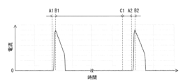
- FIG. 1 is a diagram showing an example of changes in the value of current flowing between electrodes, measured by a conventional wearable sensor.
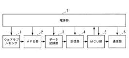
- FIG. 2 is a block diagram showing the configuration of the perspiration analyzer according to the first embodiment of the present invention.
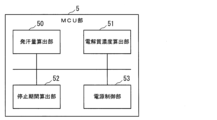
- FIG. 3 is a functional block diagram of the MCU section of the perspiration analyzer according to the first embodiment of the present invention.
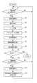
- FIG. 4 is a flow chart for explaining the operation of the perspiration analyzer according to the first embodiment of the present invention.
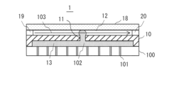
- FIG. 5 is a cross-sectional view of the wearable sensor of the perspiration analyzer according to the second embodiment of the present invention.
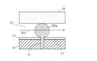
- FIG. 6 is a cross-sectional view in which FIG. 5 is enlarged.
- FIG. 5 is a cross-sectional view in which FIG. 5 is enlarged.
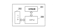
- FIG. 7 is a block diagram showing a configuration example of a computer that implements the perspiration analyzer according to the first and second embodiments of the present invention.
- FIG. 8 is a cross-sectional view of a conventional wearable sensor.
- FIG. 9 is a cross-sectional view in which FIG. 8 is enlarged.
- FIG. 1 shows an example of changes in the value of current flowing between electrodes measured by the wearable sensor disclosed in Patent Document 1.
- FIG. 1 shows an example of changes in the value of current flowing between electrodes measured by the wearable sensor disclosed in Patent Document 1.
- FIG. 8 and 9 current continues to flow during the period when sweat droplets are present between the two electrodes, and the flow rate of sweat flowing into the sensor, that is, the amount of perspiration
- the period of energization changes according to the amount of
- the peak current at the time of energization changes according to the amount of electrolyte concentration.
- the time B1 is set so that the time at which the peak current occurs is included between the time A1 and the time B1, and the sensor performs measurement only between the time A1 and the time B1.
- the power supply is controlled so that the sensor does not perform measurement until C1).
- FIG. 2 is a block diagram showing the configuration of the perspiration analyzer according to the first embodiment of the present invention.
- the perspiration analyzer includes a wearable sensor 1, an AFE (Analog Front End) section 2, a data recording section 3, a storage section 4, an MCU (Micro Control Unit) section 5, a communication section 6, and a power supply section 7. It has
- the wearable sensor 1 outputs an electrical signal (for example, a waveform current shown in FIG. 1) derived from the amount of sweat secreted from the wearer's skin and the electrolyte concentration.
- the AFE section 2 has an analog front end and amplifies weak electrical signals output from the wearable sensor 1 .
- the data recording unit 3 includes an ADC (Analog Digital Converter), converts the analog signal amplified by the AFE unit 2 into digital data at a predetermined sampling frequency, and stores the digital data in the storage unit 4 .
- the storage unit 4 stores digital data output from the data recording unit 3 .
- the storage unit 4 is realized by a non-volatile memory such as a flash memory, a volatile memory such as a DRAM (Dynamic Random Access Memory), or the like.
- the MCU unit 5 is a circuit responsible for signal processing for calculating perspiration amount and electrolyte concentration from the digital data stored in the storage unit 4 and power control.
- the communication unit 6 includes a circuit for wirelessly or wiredly transmitting measurement results and analysis results obtained by the MCU unit 5 to an external device (not shown) such as a smartphone.
- Wireless communication standards include, for example, BLE (Bluetooth (registered trademark) Low Energy).
- Wired communication standards include, for example, Ethernet (registered trademark).
- the power supply unit 7 is a circuit that plays a role of supplying power to the perspiration analyzer.
- wearable sensor 1 since the wearable sensor 1 in this embodiment is the same as that disclosed in Patent Document 1, the structure of the wearable sensor 1 will be briefly described with reference to FIGS. 8 and 9.
- FIG. As described above, wearable sensor 1 includes substrate 10 , electrodes 14 and 16 , and water absorption structure 15 .
- the base material 10 is made of, for example, a hydrophilic glass material or resin material.
- the base material 10 may be one in which the surface of a water-repellent material and the inner surface of the through-hole 11 are subjected to a surface treatment that imparts hydrophilicity.
- a concave portion 12 having a concave upper surface is formed on the upper surface of the base material 10 so as to communicate with the through hole 11 .
- a concave portion 13 having a recessed shape is formed on the lower surface of the base material 10 so as to communicate with the through hole 11 .
- the electrode 14 is made of, for example, a metal thin film formed on the surface (lower surface) of the base material 10 where the end on the entrance side of the through hole 11 opens.
- the water absorbing structure 15 include fibers such as cotton and silk, and porous ceramic substrates.
- the electrode 16 include a porous metal thin film formed on the surface of the water absorbing structure 15 by plating, a conductive polymer impregnated into the fibers of the water absorbing structure 15, and a woven conductive fiber. etc. can be mentioned.
- the wearable sensor 1 is worn on the wearer's body so that the lower surface of the base material 10 faces the wearer's skin 100 as shown in FIG.
- Reference numeral 101 in FIG. 8 denotes sweat glands of the wearer.
- sweat 102 is introduced into the through-holes 11 from the concave portions 13 of the base material 10 by capillary action. Furthermore, due to an increase in the amount of perspiration, sweat 102 rises in through-hole 11 and reaches concave portion 12 .
- a water-repellent portion 17 is provided on the inner surface of the concave portion 12 .
- the water-repellent portion 17 may be formed by applying a water-repellent surface treatment to the inner surface of the concave portion 12.
- FIG. When a water-repellent material is used for the base material 10, the water-repellent portion 17 can be provided by leaving only the inner surface of the concave portion 12 with the water-repellent material.
- the sweat 102 When the sweat 102 reaches the concave portion 12, it becomes spherical droplets 102a as shown in FIG. Furthermore, as the amount of perspiration increases, the droplet 102a increases in diameter until it reaches the electrode 16 and the absorbent structure 15. FIG.
- the droplets 102a that have reached the electrode 16 and the water absorbing structure 15 pass through many holes of the electrode 16 and many holes of the water absorbing structure 15 by capillary action, and evaporate while moving inside the water absorbing structure 15. As a result, the droplet 102a disappears. In this way, the formation and disappearance of the droplet 102a causes repeated energization between the electrodes 14 and 16 of the wearable sensor 1.
- the structures of FIGS. 8 and 9 are taken as examples, but the structure is not limited to this.
- a wearable sensor having another structure may be used as long as a current intermittently flows between the electrodes due to droplets that are intermittently generated in the wearable sensor by perspiration of the wearer.
- FIG. 3 is a functional block diagram of the MCU section 5 of this embodiment.
- the MCU unit 5 functions as a perspiration amount calculation unit 50 , an electrolyte concentration calculation unit 51 , a stop period calculation unit 52 , and a power supply control unit 53 .
- the perspiration amount calculation unit 50 calculates the amount of perspiration of the wearer based on the energization characteristics between the electrodes of the wearable sensor 1 .
- the electrolyte concentration calculator 51 calculates the electrolyte concentration in the wearer's sweat based on the current-carrying characteristics between the electrodes of the wearable sensor 1 .
- the power supply control unit 53 supplies power from the power supply unit 7 to the wearable sensor 1, the AFE unit 2, the data recording unit 3, the perspiration amount calculation unit 50, the electrolyte concentration calculation unit 51, and the communication unit 6 when the power supply stop condition is satisfied. Power supply is stopped, and power supply to wearable sensor 1, AFE unit 2, data recording unit 3, perspiration amount calculation unit 50, electrolyte concentration calculation unit 51, and communication unit 6 is resumed when the power supply stop period ends.
- the stop period calculator 52 calculates the power supply stop period based on the current-carrying characteristics between the electrodes of the wearable sensor 1 .
- FIG. 4 is a flow chart explaining the operation of the perspiration analyzer of this embodiment.
- the power control unit 53 determines whether or not the power supply suspension period determined by the suspension period calculation unit 52 has ended (step S1 in FIG. 4). The details of the power supply stop period will be described later.
- step S1 When the power control unit 53 determines that the power supply stop period has ended (YES in step S1), the power supply unit 7 communicates with the AFE unit 2, the data recording unit 3, the perspiration calculation unit 50, and the electrolyte concentration calculation unit 51.
- the supply of power supply voltage to the unit 6 is started (step S2 in FIG. 4).
- a voltage is applied between the electrodes 14 and 16 of the wearable sensor 1 through the AFE section 2 .
- the process proceeds to step S2 without executing the determination of step S1.
- the AFE section 2 detects the current flowing between the electrodes 14 and 16 of the wearable sensor 1 (step S3 in FIG. 4).
- the data recording unit 3 converts the signal detected and amplified by the AFE unit 2 into digital data at a predetermined sampling rate (step S4 in FIG. 4), and stores the digital data in the storage unit 4 (step S5 in FIG. 4). At this time, the data recording unit 3 adds sampling time information to the digital data and stores the digital data in the storage unit 4 . In this way, the storage unit 4 stores the time-series data of the current.
- the perspiration amount calculator 50 calculates the perspiration amount Q [L/(cm 2 ⁇ min)] of the wearer of the wearable sensor 1 (step S6 in Fig. 4). Specifically, the perspiration amount calculation unit 50 calculates the volume V [L] of the sweat droplet 102a as the period t [min] from the immediately preceding current peak to the latest current peak, By dividing by the area S [cm 2 ] of the wearer's skin 100, the amount of perspiration Q [L/(cm 2 ⁇ min)] can be calculated.
- the electrolyte concentration calculator 51 calculates the electrical resistivity ⁇ of sweat that varies depending on the electrolyte concentration CSW in sweat of the wearer, and calculates the electrolyte concentration CSW in the sweat from this electrical resistivity ⁇ (step S7 in FIG. 4). . Specifically, the electrolyte concentration calculation unit 51 calculates the value of the known voltage applied between the electrodes 14 and 16 by the AFE unit 2 as the current peak value at the time of the latest energization indicated by the digital data stored in the storage unit 4.
- the electrolyte concentration calculator 51 calculates the electrical resistivity ⁇ based on the resistance, the known distance between the electrodes 14 and 16 , and the cross-sectional area of sweat between the electrodes 14 and 16 .
- the cross-sectional area of sweat a specified value may be used when the cross-sectional area of sweat between the electrodes 14 and 16 is assumed to be constant.
- the electrolyte concentration calculator 51 calculates the electrolyte concentration CSW from the electrical resistivity ⁇ based on the known relationship between the electrical resistivity ⁇ and the electrolyte concentration CSW.
- the communication unit 6 transmits the calculation result of the perspiration calculation unit 50 and the calculation result of the electrolyte concentration calculation unit 51 to an external device (not shown) such as a smartphone (step S8 in FIG. 4).
- the power control unit 53 determines whether or not the power supply stop condition is satisfied (step S10 in FIG. 4).
- the time from the time when the current starts to flow between the electrodes 14 and 16 of the wearable sensor 1 to the time when the power supply stop condition is met is defined as t1 .
- the time from A1 to B1 and the time from A2 to B2 are t1 .
- the length of t 1 can change from current peak to current peak. There are, for example, the following two methods for determining the power supply stop condition.
- the first determination method assumes that the time t 3 required from the start of the current flow between the electrodes 14 and 16 to the occurrence of the current peak is known in advance.
- the power supply control unit 53 may determine that the power supply stop condition has been satisfied when a certain period of time has passed since the latest time when the current started to flow between the electrodes 14 and 16 .
- the fixed time at this time is t1 , which is set in advance as a value equal to or longer than time t3 .
- the length of time t 1 can vary from current peak to current peak.
- the power supply control unit 53 determines that the power supply stop condition is satisfied when a current peak occurs after the supply of the power supply voltage is started in the previous step S2. In this case, the time from when the current starts to flow between the electrodes 14 and 16 to when the current peak occurs is t 1 .
- step S10 the power supply unit 7 communicates with the AFE unit 2, the data recording unit 3, the perspiration calculation unit 50, and the electrolyte concentration calculation unit 51.
- the supply of power supply voltage to the unit 6 is stopped (step S11 in FIG. 4). Since the supply of the power supply voltage to the AFE section 2 is stopped, the voltage application between the electrodes 14 and 16 is also stopped.
- the stop period calculator 52 calculates the time t2 from the power supply stop time to the power supply restart time (step S12 in FIG. 4).
- the power supply stop time is B1
- the power supply restart time is C1.
- t 1 [sec] be the time from the latest time when the current started to flow between the electrodes 14 and 16 to the power supply stop time when the power supply stop condition is satisfied in step S10.
- t min [sec] be the cycle of the current peak corresponding to the wearer's maximum perspiration amount Q max .
- the suspension period calculator 52 calculates the time t 2 [sec] so as to satisfy the following formula (1). 0 ⁇ t2 ⁇ tmin - t1 (1)
- the amount of perspiration is calculated from the volume of sweat droplets, the current peak period, and the area of the wearer's skin covered with the wearable sensor 1. Therefore, the current peak period corresponding to the maximum amount of perspiration Q max It is possible to obtain t min in advance. A known value obtained from past measurements may be used as the maximum amount of perspiration Q max .
- the stop period calculator 52 may set t 2 to the longest period of time that satisfies the condition of formula (1).
- the stop period calculator 52 may set t 2 to be the longest time in the range that satisfies the condition of formula (2).
- the predetermined value .DELTA.Q (.DELTA.Q>0) is a parameter related to the rate of increase in the amount of perspiration of the wearer, and may be preset based on the results obtained in past measurements.
- the stop period calculator 52 may set t2 to be the longest time in the range that satisfies the condition of formula (3). Further, when the sum Q+ ⁇ Q of the latest perspiration amount Q and the predetermined value ⁇ Q is equal to or greater than the maximum perspiration amount Q max (Q+ ⁇ Q ⁇ Q max ), the stop period calculation unit 52 calculates the time t so as to satisfy the above equation (1). 2 Calculate [sec].
- the perspiration analyzer repeats the processes of steps S1 to S8 and S10 to S12 until, for example, the wearer gives an instruction to end the measurement (YES in step S9 in FIG. 4).
- the power supply control unit 53 determines in the next step S1 that the elapsed time from the power supply stop time at which the power supply stop condition is satisfied in the immediately preceding step S10 is less than t2 calculated by the stop period calculation unit 52, , waits while the power supply is stopped.
- the power control unit 53 determines that the power supply stop period has ended when the elapsed time from the power supply stop time is t2 or longer.
- the wearable sensor 1, the AFE unit 2, the data recording unit 3, the sweat amount calculation unit 50, and the electrolyte concentration calculation unit are operated for the time required to calculate the amount of perspiration and the electrolyte concentration. Since the power supply voltage is supplied to 51 and the communication unit 6, it is possible to measure biometric information such as the amount of perspiration and electrolyte concentration while saving power.
- FIG. 5 is a cross-sectional view of the wearable sensor 1 of this embodiment
- FIG. 6 is an enlarged view of FIG.
- the wearable sensor 1 includes a substrate 10 having a through hole 11 serving as a liquid flow path and a recess 12 communicating with the outlet side end of the through hole 11, and the liquid flows out from the outlet side opening of the through hole 11 to the recess 12.
- a water absorbing structure 18 arranged on the outlet side surface (upper surface) of the base material 10 so as to be in contact with the liquid that has been applied;
- a laser diode (LD) 19 that emits light to a path in the recess 12 that passes through the position above the opening on the exit side, and a laser diode (LD) 19 that faces the LD 19 in the recess 12 across the position above the opening on the exit side of the through hole 11 .
- PD photodiode
- Examples of the water absorbing structure 18 include fibers such as cotton and silk, and porous ceramic substrates.
- the water absorbing structure 18 does not need to cover the entire surface of the outlet side opening of the through hole 11 and the concave portion 12, and is arranged so as to be able to come into contact with droplets flowing out from the outlet side opening of the through hole 11 into the concave portion 12. It is good if there is.
- the wearable sensor 1 is worn on the wearer's body so that the lower surface of the base material 10 faces the wearer's skin 100 as shown in FIG.
- sweat 102 is introduced into the through-holes 11 from the concave portions 13 of the base material 10 by capillary action. Furthermore, due to an increase in the amount of perspiration, sweat 102 rises in through-hole 11 and reaches concave portion 12 provided on the upper surface of base material 10 so as to communicate with through-hole 11 (FIG. 6).
- a water-repellent portion 17 is provided on the inner surface of the recess 12 as in the first embodiment.
- the sweat 102 reaches the concave portion 12, it becomes spherical droplets 102a as shown in FIG. Further, as the amount of perspiration increases, the droplets 102a increase in diameter until they reach the absorbent structure 18 .
- the droplets 102a reaching the water absorbing structure 18 pass through many holes of the water absorbing structure 18 due to capillary action and evaporate while moving inside the water absorbing structure 18 . As a result, the droplet 102a disappears.
- a PD 20 as a light receiving element receives light from the LD 19 .
- the light 103 emitted from the LD 19 propagates through each medium in the order of the air in the recess 12, the droplet 102a, and the air in the recess 12, and enters the PD 20.
- the droplet 102 a disappears, the light 103 propagates through the air inside the recess 12 and enters the PD 20 .
- the droplet 102a is formed again, the light 103 propagates through each medium in the order of the air in the recess 12, the droplet 102a, and the air in the recess 12, and enters the PD20. In this way, the difference in the medium through which the light 103 propagates is reflected in the amount of light received by the PD 20 . That is, the photocurrent flowing through the PD 20 changes due to the formation and disappearance of the droplet 102a.
- the configuration of the AFE section 2, the data recording section 3, the storage section 4, the MCU section 5, the communication section 6, and the power supply section 7 of the perspiration analyzer is the same as that of the first embodiment.
- the AFE section 2 may amplify the output signal (photocurrent) of the PD 20 .
- the photocurrent of the PD 20 decreases, and when the droplet 102a disappears, the photocurrent of the PD 20 increases. Therefore, instead of the time when the current starts to flow between the electrodes 14 and 16 in the first embodiment, the time when the photocurrent of the PD 20 starts to change due to the droplet 102a may be used.
- the stop period calculation unit 52 and the power supply control unit 53 determine the time when the photocurrent of the PD 20 changes from exceeding the current threshold to below the current threshold as the time when the photocurrent starts to change (first embodiment). time at which the current starts to flow).
- the upward peak of the current between the electrodes 14 and 16 is detected to determine whether the power supply stop condition is met or not, and the power supply stop period t 2 , the amount of perspiration Q, and the electrolyte concentration CSW. is calculated.
- the downward peak of the photocurrent of the PD 20 is detected to determine whether the power supply stop condition is met or not, and the power supply stop period t 2 , the amount of perspiration Q, and the electrolyte concentration CSW are calculated. should be done.
- the power control unit 53 communicates with the LD 19 and PD 20 of the wearable sensor 1, the AFE unit 2, the data recording unit 3, the perspiration calculation unit 50, and the electrolyte concentration calculation unit 51 from the power supply unit 7 in step S2.
- step S11 power supply voltage is applied from the power supply unit 7 to the LD 19, the PD 20, the AFE unit 2, the data recording unit 3, the perspiration calculation unit 50, the electrolyte concentration calculation unit 51, and the communication unit 6.
- step S11 power supply voltage is applied from the power supply unit 7 to the LD 19, the PD 20, the AFE unit 2, the data recording unit 3, the perspiration calculation unit 50, the electrolyte concentration calculation unit 51, and the communication unit 6.
- Other configurations are the same as those of the first embodiment.
- a wearable sensor as described in Patent Document 1 and International Publication WO2021/038758 detects an electrical signal derived from the amount of perspiration and electrolyte concentration of the user, and detects the electrical signal.
- An example of controlling the timing of stopping and restarting power supply based on time-series data of signals has been described.
- the present invention can also be applied to the case where wearable sensors measure the user's electrocardiogram waveform, respiratory motion, pulse wave, and other periodic biological information, and calculate feature quantities such as heart rate, respiration rate, and pulse rate. It is possible.
- the data recording unit 3, the storage unit 4, the MCU unit 5, and the communication unit 6 described in the first and second embodiments are a computer having a CPU (Central Processing Unit), a storage device, and an interface, and these hardware It can be implemented by a program that controls resources.
- a configuration example of this computer is shown in FIG.
- the computer comprises a CPU 200 , a storage device 201 and an interface device (I/F) 202 .
- the I/F 202 is connected to the hardware such as the ADC of the data recording unit 3, the hardware of the communication unit 6, the power supply unit 7, and the like.
- a program for implementing the perspiration analysis method of the present invention is stored in storage device 201 .
- the CPU 200 executes the processes described in the first and second embodiments according to programs stored in the storage device 201 .
- the present invention can be applied to techniques for analyzing the amount of perspiration and electrolyte concentration in sweat.
Landscapes
- Health & Medical Sciences (AREA)
- Life Sciences & Earth Sciences (AREA)
- Physics & Mathematics (AREA)
- Heart & Thoracic Surgery (AREA)
- Molecular Biology (AREA)
- Veterinary Medicine (AREA)
- Biophysics (AREA)
- Pathology (AREA)
- Engineering & Computer Science (AREA)
- Biomedical Technology (AREA)
- Public Health (AREA)
- Medical Informatics (AREA)
- General Health & Medical Sciences (AREA)
- Surgery (AREA)
- Animal Behavior & Ethology (AREA)
- Optics & Photonics (AREA)
- Physiology (AREA)
- Endocrinology (AREA)
- Gastroenterology & Hepatology (AREA)
- Measuring And Recording Apparatus For Diagnosis (AREA)
Priority Applications (3)
| Application Number | Priority Date | Filing Date | Title |
|---|---|---|---|
| US18/692,197 US20240382114A1 (en) | 2021-10-26 | 2021-10-26 | Perspiration analysis device and method |
| PCT/JP2021/039419 WO2023073797A1 (ja) | 2021-10-26 | 2021-10-26 | 発汗分析装置および方法 |
| JP2023555922A JP7589831B2 (ja) | 2021-10-26 | 2021-10-26 | 発汗分析装置および方法 |
Applications Claiming Priority (1)
| Application Number | Priority Date | Filing Date | Title |
|---|---|---|---|
| PCT/JP2021/039419 WO2023073797A1 (ja) | 2021-10-26 | 2021-10-26 | 発汗分析装置および方法 |
Publications (1)
| Publication Number | Publication Date |
|---|---|
| WO2023073797A1 true WO2023073797A1 (ja) | 2023-05-04 |
Family
ID=86159225
Family Applications (1)
| Application Number | Title | Priority Date | Filing Date |
|---|---|---|---|
| PCT/JP2021/039419 Ceased WO2023073797A1 (ja) | 2021-10-26 | 2021-10-26 | 発汗分析装置および方法 |
Country Status (3)
| Country | Link |
|---|---|
| US (1) | US20240382114A1 (cg-RX-API-DMAC7.html) |
| JP (1) | JP7589831B2 (cg-RX-API-DMAC7.html) |
| WO (1) | WO2023073797A1 (cg-RX-API-DMAC7.html) |
Citations (4)
| Publication number | Priority date | Publication date | Assignee | Title |
|---|---|---|---|---|
| WO2021038742A1 (ja) * | 2019-08-28 | 2021-03-04 | 日本電信電話株式会社 | ウェアラブルセンサ、発汗分析装置および方法 |
| WO2021038758A1 (ja) * | 2019-08-28 | 2021-03-04 | 日本電信電話株式会社 | ウェアラブルセンサ、発汗分析装置および方法 |
| WO2021074099A1 (en) * | 2019-10-14 | 2021-04-22 | Koninklijke Philips N.V. | System and method for sweat rate determination |
| WO2021074010A1 (en) * | 2019-10-14 | 2021-04-22 | Koninklijke Philips N.V. | Apparatus, system, and method for sweat flow monitoring |
Family Cites Families (6)
| Publication number | Priority date | Publication date | Assignee | Title |
|---|---|---|---|---|
| WO2013033724A1 (en) * | 2011-09-01 | 2013-03-07 | Mc10, Inc. | Electronics for detection of a condition of tissue |
| US10136831B2 (en) * | 2013-10-18 | 2018-11-27 | University Of Cincinnati | Sweat sensing with chronological assurance |
| WO2016140961A1 (en) * | 2015-03-02 | 2016-09-09 | Mc10, Inc. | Perspiration sensor |
| US20190029654A1 (en) * | 2016-01-15 | 2019-01-31 | University Of Cincinnati | Advanced electroporation devices and methods for analyte access in biofluids |
| US10736565B2 (en) * | 2016-10-14 | 2020-08-11 | Eccrine Systems, Inc. | Sweat electrolyte loss monitoring devices |
| JP7167824B2 (ja) * | 2019-04-08 | 2022-11-09 | 日本電信電話株式会社 | 発汗分析装置 |
-
2021
- 2021-10-26 WO PCT/JP2021/039419 patent/WO2023073797A1/ja not_active Ceased
- 2021-10-26 US US18/692,197 patent/US20240382114A1/en active Pending
- 2021-10-26 JP JP2023555922A patent/JP7589831B2/ja active Active
Patent Citations (4)
| Publication number | Priority date | Publication date | Assignee | Title |
|---|---|---|---|---|
| WO2021038742A1 (ja) * | 2019-08-28 | 2021-03-04 | 日本電信電話株式会社 | ウェアラブルセンサ、発汗分析装置および方法 |
| WO2021038758A1 (ja) * | 2019-08-28 | 2021-03-04 | 日本電信電話株式会社 | ウェアラブルセンサ、発汗分析装置および方法 |
| WO2021074099A1 (en) * | 2019-10-14 | 2021-04-22 | Koninklijke Philips N.V. | System and method for sweat rate determination |
| WO2021074010A1 (en) * | 2019-10-14 | 2021-04-22 | Koninklijke Philips N.V. | Apparatus, system, and method for sweat flow monitoring |
Non-Patent Citations (1)
| Title |
|---|
| JESSICA FRANCIS, ISAAC STAMPER, JASON HEIKENFELD, ELIOT F. GOMEZ: "Digital nanoliter to milliliter flow rate sensor with in vivo demonstration for continuous sweat rate measurement", LAB ON A CHIP, vol. 19, no. 1, 1 January 2019 (2019-01-01), UK , pages 178 - 185, XP055679527, ISSN: 1473-0197, DOI: 10.1039/C8LC00968F * |
Also Published As
| Publication number | Publication date |
|---|---|
| JP7589831B2 (ja) | 2024-11-26 |
| US20240382114A1 (en) | 2024-11-21 |
| JPWO2023073797A1 (cg-RX-API-DMAC7.html) | 2023-05-04 |
Similar Documents
| Publication | Publication Date | Title |
|---|---|---|
| EP3370605B1 (en) | Energy efficient system and method for physiological monitoring | |
| US20200138377A1 (en) | Wearable device, system and method | |
| US12453508B2 (en) | Pathological state detection using dynamically determined body data variability range values | |
| US12575762B2 (en) | Wearable sensor and sweating analysis device | |
| US20220322997A1 (en) | Wearable Sensor, Perspiration Analysis Device and Method | |
| JP6228086B2 (ja) | 生体信号取得装置および方法 | |
| JP4916748B2 (ja) | 分析装置および分析方法 | |
| JP7589831B2 (ja) | 発汗分析装置および方法 | |
| CN100471451C (zh) | 在耳垂上测量经皮二氧化碳分压的方法 | |
| CN120114023B (zh) | 一种用于治疗静脉血栓的贴片式血栓监测与no释放闭环系统 | |
| JP2024147181A (ja) | 発汗分析装置および方法 | |
| US12484807B2 (en) | Wearable sensor, perspiration analysis device and method | |
| JP7111254B2 (ja) | 発汗分析装置 | |
| JP7761143B2 (ja) | 発汗分析装置および方法 | |
| JP2013066576A (ja) | 生体信号測定電極、生体信号測定装置及び生体信号測定方法 | |
| JP7761135B2 (ja) | 発汗分析装置および方法 | |
| US20230118172A1 (en) | Wearable Device, Perspiration Analysis Device, and Perspiration Analysis Method | |
| US20230111975A1 (en) | Wearable Device, Perspiration Analysis Device, and Perspiration Analysis Method | |
| JP7420212B2 (ja) | 発汗分析装置、および発汗分析方法 | |
| JP7420213B2 (ja) | 発汗分析装置、および発汗分析方法 | |
| CN107333466A (zh) | 用于无创伤地确定分析物浓度的装置和方法 | |
| JP2026011429A (ja) | 生体情報計測装置、生体情報計測システム、生体情報計測方法および生体情報計測プログラム | |
| US20230082487A1 (en) | Wearable Device, Perspiration Analysis Device, and Perspiration Analysis Method | |
| JP2548325Y2 (ja) | ヒーティングパワー経皮酸素分圧測定装置 |
Legal Events
| Date | Code | Title | Description |
|---|---|---|---|
| 121 | Ep: the epo has been informed by wipo that ep was designated in this application |
Ref document number: 21962346 Country of ref document: EP Kind code of ref document: A1 |
|
| WWE | Wipo information: entry into national phase |
Ref document number: 2023555922 Country of ref document: JP |
|
| WWE | Wipo information: entry into national phase |
Ref document number: 18692197 Country of ref document: US |
|
| NENP | Non-entry into the national phase |
Ref country code: DE |
|
| 122 | Ep: pct application non-entry in european phase |
Ref document number: 21962346 Country of ref document: EP Kind code of ref document: A1 |