WO2023068334A1 - Vehicle drive device - Google Patents
Vehicle drive device Download PDFInfo
- Publication number
- WO2023068334A1 WO2023068334A1 PCT/JP2022/039140 JP2022039140W WO2023068334A1 WO 2023068334 A1 WO2023068334 A1 WO 2023068334A1 JP 2022039140 W JP2022039140 W JP 2022039140W WO 2023068334 A1 WO2023068334 A1 WO 2023068334A1
- Authority
- WO
- WIPO (PCT)
- Prior art keywords
- gear mechanism
- axial direction
- gear
- output
- rotating element
- Prior art date
Links
- 230000007246 mechanism Effects 0.000 claims description 296
- 230000002093 peripheral effect Effects 0.000 claims description 47
- 238000003466 welding Methods 0.000 claims description 5
- 238000006073 displacement reaction Methods 0.000 abstract 1
- 238000010586 diagram Methods 0.000 description 13
- 238000005192 partition Methods 0.000 description 13
- 230000009467 reduction Effects 0.000 description 13
- 230000009471 action Effects 0.000 description 12
- 239000000969 carrier Substances 0.000 description 4
- 239000003638 chemical reducing agent Substances 0.000 description 4
- 230000005540 biological transmission Effects 0.000 description 3
- 230000008878 coupling Effects 0.000 description 2
- 238000010168 coupling process Methods 0.000 description 2
- 238000005859 coupling reaction Methods 0.000 description 2
- 239000003990 capacitor Substances 0.000 description 1
- 238000005516 engineering process Methods 0.000 description 1
- 230000004048 modification Effects 0.000 description 1
- 238000012986 modification Methods 0.000 description 1
Images


Classifications
-
- B—PERFORMING OPERATIONS; TRANSPORTING
- B60—VEHICLES IN GENERAL
- B60K—ARRANGEMENT OR MOUNTING OF PROPULSION UNITS OR OF TRANSMISSIONS IN VEHICLES; ARRANGEMENT OR MOUNTING OF PLURAL DIVERSE PRIME-MOVERS IN VEHICLES; AUXILIARY DRIVES FOR VEHICLES; INSTRUMENTATION OR DASHBOARDS FOR VEHICLES; ARRANGEMENTS IN CONNECTION WITH COOLING, AIR INTAKE, GAS EXHAUST OR FUEL SUPPLY OF PROPULSION UNITS IN VEHICLES
- B60K1/00—Arrangement or mounting of electrical propulsion units
-
- F—MECHANICAL ENGINEERING; LIGHTING; HEATING; WEAPONS; BLASTING
- F16—ENGINEERING ELEMENTS AND UNITS; GENERAL MEASURES FOR PRODUCING AND MAINTAINING EFFECTIVE FUNCTIONING OF MACHINES OR INSTALLATIONS; THERMAL INSULATION IN GENERAL
- F16H—GEARING
- F16H1/00—Toothed gearings for conveying rotary motion
- F16H1/28—Toothed gearings for conveying rotary motion with gears having orbital motion
-
- F—MECHANICAL ENGINEERING; LIGHTING; HEATING; WEAPONS; BLASTING
- F16—ENGINEERING ELEMENTS AND UNITS; GENERAL MEASURES FOR PRODUCING AND MAINTAINING EFFECTIVE FUNCTIONING OF MACHINES OR INSTALLATIONS; THERMAL INSULATION IN GENERAL
- F16H—GEARING
- F16H48/00—Differential gearings
- F16H48/06—Differential gearings with gears having orbital motion
- F16H48/10—Differential gearings with gears having orbital motion with orbital spur gears
-
- H—ELECTRICITY
- H02—GENERATION; CONVERSION OR DISTRIBUTION OF ELECTRIC POWER
- H02K—DYNAMO-ELECTRIC MACHINES
- H02K7/00—Arrangements for handling mechanical energy structurally associated with dynamo-electric machines, e.g. structural association with mechanical driving motors or auxiliary dynamo-electric machines
- H02K7/10—Structural association with clutches, brakes, gears, pulleys or mechanical starters
- H02K7/116—Structural association with clutches, brakes, gears, pulleys or mechanical starters with gears
Definitions
- the present invention relates to a vehicle drive device that includes a rotating electric machine and a planetary gear mechanism.
- Patent Document 1 An example of such a vehicle driving device is disclosed in Patent Document 1 and Patent Document 2 below.
- reference numerals in patent documents to be referenced are quoted in parentheses.
- the planetary gear mechanism (4) of the vehicle drive device (1) of Patent Document 1 includes a sun gear (41), a ring gear (42), and carriers (6, 7).
- the sun gear (41) is coupled to rotate integrally with the rotor (21) of the rotating electric machine (2).
- a ring gear (42) is fixed to the case (10).
- the carriers (6, 7) rotatably support a first pinion gear (431) and a second pinion gear (432) which are connected to rotate integrally with each other.
- the first pinion gear (431) meshes with the sun gear (41).
- the second pinion gear (432) has a smaller diameter than the first pinion gear (431) and meshes with the ring gear (42).
- the carriers (6, 7) are connected to rotate integrally with the differential case (50) of the output differential gear mechanism (5).
- the planetary gear mechanism (4) decelerates the rotation of the rotor (21) and transmits it to the output differential gear mechanism (5).
- the planetary gear mechanism (3) of the vehicle drive device of Patent Document 2 includes a sun gear (S1), a carrier (C), a first ring gear (R1), and a second ring gear (R2). (see FIG. 4 of Patent Document 2).
- the sun gear (S1) is coupled to rotate integrally with the rotor of the rotating electric machine (2).
- the carrier (C) rotatably supports a first pinion gear (P1) and a second pinion gear (P2) which are connected to rotate integrally with each other.
- the first pinion gear (P1) meshes with the sun gear (S1) and the first ring gear (R1).
- the second pinion gear (P2) has a smaller diameter than the first pinion gear (P1) and meshes with the second ring gear (R2).
- a first ring gear (R1) is fixed to the case (1).
- the second ring gear (R2) is connected to an output differential gear mechanism (4), which is a bevel gear type differential gear mechanism.
- the planetary gear mechanism (3) decelerates the rotation of the rotor of the rotating electric machine (2) and transmits it to the output differential gear mechanism (4).
- JP 2021-124185 A Japanese Patent Application Laid-Open No. 2002-104001
- the sun gear (41) is the input element of the planetary gear mechanism (4)
- the carrier (6, 7) is the output element of the planetary gear mechanism (4).
- the planetary gear mechanism (4) is arranged radially outside the bevel gear type output differential gear mechanism (5). Therefore, the axial dimension of the vehicle drive device (1) is kept small.
- the carriers (6, 7) supporting the first pinion gear (431) and the second pinion gear (432) are integrated with the differential case (50) of the output differential gear mechanism (5). connected for rotation. Therefore, when the planetary gear mechanism (4) is arranged radially outside the output differential gear mechanism (5), the vehicle drive device (1) tends to be radially large.
- the planetary gear mechanism (3) of the vehicle drive device of Patent Document 2 has a configuration in which it is easy to secure a large reduction ratio while keeping the radial dimension small.
- the differential case (DC) of the output differential gear mechanism (4) is arranged axially with respect to the plurality of gears (DP1, DP2, DSI1, DSI2) constituting the output differential gear mechanism (4). It is generally supported against the case (1) on both sides.
- the vehicle drive device of Patent Document 2 does not describe a support structure for such an output differential gear mechanism (4).
- the characteristic configuration of the vehicle drive system is as follows.
- a rotating electric machine having a rotor; a first output member drivingly connected to the first wheel; a second output member drivingly connected to the second wheel; a planetary gear mechanism that decelerates rotation of the rotor; an output differential gear mechanism comprising an input element and distributing rotation transmitted from the planetary gear mechanism to the input element to the first output member and the second output member;
- a vehicle drive device comprising: a case accommodating the rotating electric machine, the planetary gear mechanism, and the output differential gear mechanism, the rotating electric machine, the first output member, the second output member, the planetary gear mechanism, and the output differential gear mechanism are coaxially arranged;
- the planetary gear mechanism includes a first rotating element, a second rotating element, a third rotating element, and a fourth rotating element, and the first rotating element, the second rotating element, the third rotating element, and the fourth rotating element.
- the first rotating element is a first sun gear coupled to rotate integrally with the rotor
- the third rotating element is a first ring gear connected to the case
- the fourth rotating element is a second ring gear coupled to rotate integrally with the input element
- the second rotating element is a first carrier that rotatably supports a first pinion gear and a second pinion gear that rotate integrally with each other, the first pinion gear meshes with the first sun gear and the first ring gear;
- the second pinion gear has a smaller diameter than the first pinion gear and meshes with the second ring gear;
- the first rotating element of the planetary gear mechanism is connected to the rotor.
- the third rotating element of the planetary gear mechanism is connected to the case, and the fourth rotating element of the planetary gear mechanism is connected to the input element of the output differential gear mechanism.
- each of the third rotating element and the fourth rotating element of the planetary gear mechanism is a ring gear. This makes it easy to secure a large reduction ratio (for example, 17 to 22) for the planetary gear mechanism that functions as a speed reducer that reduces the rotation of the rotor and transmits it to the output differential gear mechanism.
- the fourth rotating element connected to the input element of the output differential gear mechanism is the ring gear.
- the rotating element connected to the input element of the differential gear mechanism for output is a sun gear or a carrier
- the radial dimension of the planetary gear mechanism can be kept small, and the planetary gear mechanism can be used as the differential gear mechanism for output. It is easy to dispose close to the gear mechanism in the axial direction.
- the third rotating element connected to the case is a ring gear. As a result, it is easy to provide a configuration in which a support member or the like extending in the radial direction, which is required when the sun gear or carrier is connected to the case, can be omitted. Therefore, it is easy to keep the axial dimension of the vehicle drive device small.
- the first sun gear as the first rotating element of the planetary gear mechanism is radially supported by the case via the first support bearing.
- the second ring gear as the fourth rotating element of the planetary gear mechanism and the input element of the output differential gear mechanism are connected in a state in which relative movement in the radial direction is restricted.
- the input element of the output differential gear mechanism can be radially supported by utilizing the aligning action (self-aligning action) of the planetary gear mechanism.
- a large reduction ratio can be secured for the planetary gear mechanism and the differential gear mechanism for output can be secured. It is easy to reduce the size of the vehicular drive device while appropriately supporting it.
- 1 is a skeleton diagram of a vehicle drive system according to a first embodiment; Velocity diagrams of the planetary gear mechanism and output differential gear mechanism according to the first embodiment Sectional view along the axial direction of the vehicle drive device according to the second embodiment A skeleton diagram of a vehicle drive system according to a second embodiment. Partially enlarged view of a cross-sectional view along the axial direction of the vehicle drive device according to the second embodiment Partially enlarged view of a cross-sectional view along the axial direction of the vehicle drive device according to the third embodiment
- the vehicle drive device 100 includes a rotating electric machine 1 having a stator 11 and a rotor 12, a first output member 2 drivingly connected to a first wheel W1, and a second wheel W2. , a planetary gear mechanism 4 , an output differential gear mechanism 5 , and a case 9 .
- driving connection refers to a state in which two rotating elements are connected so as to be able to transmit a driving force, and the two rotating elements are connected so as to rotate integrally. It includes a state in which two rotating elements are connected so as to be able to transmit driving force via one or more transmission members.
- Such transmission members include various members that transmit rotation at the same speed or at different speeds, such as shafts, gear mechanisms, belts, and chains.
- the transmission member may include an engagement device for selectively transmitting rotation and driving force, such as a friction engagement device and a mesh type engagement device.
- the direction along the rotation axis of the rotor 12 is defined as “axial direction L".
- One side in the axial direction L is referred to as “first axial side L1”, and the other side in the axial direction L is referred to as “second axial side L2".
- a direction orthogonal to the rotation axis of the rotor 12 is defined as a "radial direction R".
- the rotation axis side of the rotor 12 is defined as “radial inner side R1", and the opposite side is defined as “radial outer side R2".
- the direction in which the rotor 12 rotates around the rotation axis is defined as “circumferential direction C”.
- the rotating electric machine 1, the first output member 2, the second output member 3, the planetary gear mechanism 4, and the output differential gear mechanism 5 are coaxially arranged.
- the output differential gear mechanism 5, the planetary gear mechanism 4, and the rotating electric machine 1 are arranged in the order described from the first axial side L1 toward the second axial side L2.
- a part of the second output member 3 is arranged so as to overlap with the rotary electric machine 1 when viewed in the radial direction R. As shown in FIG.
- overlapping in a particular direction view means that when a virtual straight line parallel to the line-of-sight direction is moved in each direction orthogonal to the virtual straight line, the virtual straight line is two It refers to the existence of at least a part of an area that intersects two elements.
- the rotating electric machine 1, the planetary gear mechanism 4, and the output differential gear mechanism 5 are housed in a case 9.
- the first output member 2 and the second output member 3 are housed in the case 9 in a state where their parts are exposed to the outside of the case 9 .
- the case 9 includes a peripheral wall portion 91, a first side wall portion 92, a second side wall portion 93, a partition wall portion 94, and a cover portion 95 in this embodiment.
- the peripheral wall portion 91 is formed in a tubular shape covering the radial outer side R2 of the rotary electric machine 1, the first output member 2, the second output member 3, the planetary gear mechanism 4, and the output differential gear mechanism 5.
- the first side wall portion 92, the second side wall portion 93, and the partition wall portion 94 are formed to extend in the radial direction R and the circumferential direction C, respectively.
- the cover portion 95 is provided so as to cover a portion of the second side wall portion 93 from the axial second side L2.
- the first side wall portion 92 is formed to cover the first axial side L1 of the output differential gear mechanism 5 .
- the second side wall portion 93 is formed so as to cover the second axial side L2 of the rotary electric machine 1 .
- the partition wall portion 94 is arranged between the rotary electric machine 1 and the planetary gear mechanism 4 in the axial direction L.
- the cover portion 95 is joined to the second side wall portion 93 from the second side L2 in the axial direction.
- the first side wall portion 92 is formed integrally with the peripheral wall portion 91 so as to block the opening of the peripheral wall portion 91 on the first axial side L1.
- the second side wall portion 93 is formed integrally with the peripheral wall portion 91 so as to block the opening of the peripheral wall portion 91 on the axial second side L2.
- the peripheral wall portion 91 is divided at a plurality of locations (here, two locations) in the axial direction L. As shown in FIG. The divided portions of the peripheral wall portion 91 are joined together and fastened by fastening members such as bolts (not shown).
- the rotating electrical machine 1 functions as a driving force source for the first wheel W1 and the second wheel W2 (see FIG. 2).
- the rotary electric machine 1 has a function as a motor (electric motor) that receives power supply and generates power, and a function as a generator (generator) that receives power supply and generates power.
- the rotary electric machine 1 is electrically connected to a power storage device (not shown) such as a battery or a capacitor. Then, the rotating electric machine 1 is powered by the electric power stored in the power storage device to generate a driving force. Further, the rotary electric machine 1 generates power by the driving force transmitted from the first wheel W1 and the second wheel W2, and charges the power storage device.
- the stator 11 of the rotating electric machine 1 has a cylindrical stator core 11a.
- Stator core 11a is fixed to non-rotating member NR.
- the stator core 11a is fixed to the peripheral wall portion 91 of the case 9 as the non-rotating member NR.
- a rotor 12 of the rotating electric machine 1 includes a cylindrical rotor core 12a.
- the rotor core 12a is rotatably supported with respect to the stator core 11a.
- the rotor 12 further includes a rotor shaft 12b coupled to rotate integrally with the rotor core 12a.
- the rotating electrical machine 1 is an inner rotor type rotating electrical machine. Therefore, the rotor core 12a is arranged radially inward R1 with respect to the stator core 11a. Further, the rotor shaft 12b is arranged radially inward R1 with respect to the rotor core 12a.
- the rotating electrical machine 1 is a rotating field type rotating electrical machine. Therefore, the stator 11 further includes a coil 11b.
- the coil 11b has a first coil end portion 11c protruding to the first axial side L1 with respect to the stator core 11a and a second coil end portion protruding to the second axial side L2 from the stator core 11a. 11d is wound around the stator core 11a.
- the rotor core 12a is provided with permanent magnets.
- the rotor shaft 12b is formed in a cylindrical shape having an axial center along the axial direction L. Further, the rotor shaft 12b is arranged so as to protrude on both sides in the axial direction L from the rotor core 12a. In the present embodiment, the portion of the rotor shaft 12b that protrudes from the rotor core 12a to the first side L1 in the axial direction is arranged to penetrate the partition wall portion 94 of the case 9 in the axial direction L. As shown in FIG. A portion of the rotor shaft 12b that protrudes from the rotor core 12a toward the first side L1 in the axial direction is rotatably supported by the partition wall 94 via a first bearing B1.
- a portion of the rotor shaft 12b that protrudes from the rotor core 12a toward the second side L2 in the axial direction is rotatably supported by the second side wall portion 93 via a second bearing B2.
- a rotation sensor 13 that detects rotation of the rotor 12 is provided integrally with the first bearing B1.
- the planetary gear mechanism 4 includes a first rotating element E1, a second rotating element E2, a third rotating element E3, and a fourth rotating element E4.
- the planetary gear mechanism 4 is configured such that the rotation speeds of the first rotation element E1, the second rotation element E2, the third rotation element E3, and the fourth rotation element E4 are in the order described.
- the “order of rotational speed” refers to the order of rotational speed in the rotating state of each rotating element.
- the rotation speed of each rotating element changes depending on the rotation state of the planetary gear mechanism, but the order of the rotation speed of each rotating element is fixed because it is determined by the structure of the planetary gear mechanism.
- the order of rotation speed of each rotating element is the same as the order of arrangement in the velocity diagram (see FIG. 3) of each rotating element.
- the “arrangement order of each rotating element in the velocity diagram” is the order in which the axes corresponding to each rotating element in the velocity diagram are arranged along the direction perpendicular to the axis.
- the arrangement direction of the shaft corresponding to each rotating element in the velocity diagram differs depending on how the velocity diagram is drawn, but the order of arrangement is fixed because it is determined by the structure of the planetary gear mechanism.
- the output differential gear mechanism 5 has an input element Ei.
- the output differential gear mechanism 5 is configured to distribute the rotation transmitted from the planetary gear mechanism 4 to the input element Ei to the first output member 2 and the second output member 3 .
- the output differential gear mechanism 5 is a planetary gear mechanism including a fifth rotating element E5, a sixth rotating element E6, and a seventh rotating element E7.
- the output differential gear mechanism 5 is configured such that the rotation speeds of the fifth rotation element E5, the sixth rotation element E6, and the seventh rotation element E7 are arranged in the described order.
- the fifth rotating element E5 is connected to the first output member 2.
- the seventh rotating element E7 is connected to the second output member 3. As shown in FIG.
- the planetary gear mechanism 4 functions as a speed reducer that reduces the speed of rotation of the rotor 12 and transmits it to the output differential gear mechanism 5 .
- the first rotating element E1 of the planetary gear mechanism 4 is connected to rotate integrally with the rotor 12 .
- a third rotating element E3 of the planetary gear mechanism 4 is connected to the case 9 .
- the fourth rotating element E4 of the planetary gear mechanism 4 is connected to the input element Ei of the output differential gear mechanism 5 so as to rotate together.
- the fourth rotating element E4 is configured integrally with the input element Ei.
- the input element Ei is the sixth rotation element E6.
- the first rotating element E1 of the planetary gear mechanism 4 is the first sun gear SG1.
- the first sun gear SG1 is supported in the radial direction R with respect to the case 9 via the first bearing B1.
- the first bearing B ⁇ b>1 corresponds to a “first support bearing” that supports the first sun gear SG ⁇ b>1 in the radial direction R with respect to the case 9 .
- the first sun gear SG1 is coupled to rotate integrally with the rotor shaft 12b. Further, as described above, in the present embodiment, the portion of the rotor shaft 12b that protrudes from the rotor core 12a toward the first side L1 in the axial direction is rotatable with respect to the partition wall portion 94 of the case 9 via the first bearing B1.
- the first bearing B1 is supported by the partition wall portion 94, and is configured to support the first sun gear SG1 in the radial direction R and the rotor 12 in the radial direction R.
- the partition wall portion 94 corresponds to a “first support wall portion” arranged between the rotary electric machine 1 and the planetary gear mechanism 4 in the axial direction L.
- the first sun gear SG1 is formed integrally with the rotor shaft 12b.
- the second rotating element E2 of the planetary gear mechanism 4 is the first carrier CR1.
- the first carrier CR1 rotatably supports a first pinion gear PG1 and a second pinion gear PG2 that rotate integrally with each other.
- the first pinion gear PG1 meshes with the first sun gear SG1 and the first ring gear RG1.
- the second pinion gear PG2 meshes with the second ring gear RG2.
- the second pinion gear PG2 has a smaller diameter than the first pinion gear PG1.
- Each of the third rotating element E3 and the fourth rotating element E4 of the planetary gear mechanism 4 is a ring gear.
- the third rotating element E3 is the first ring gear RG1.
- the fourth rotating element E4 is the second ring gear RG2.
- the sixth rotating element E6 of the output differential gear mechanism 5 is the third ring gear RG3. That is, in the present embodiment, the second ring gear RG2 as the fourth rotating element E4 of the planetary gear mechanism 4 and the third ring gear RG3 as the sixth rotating element E6 which is the input element Ei of the output differential gear mechanism 5 are connected so as to rotate integrally.
- the second ring gear RG2 and the input element Ei are connected in a state in which relative movement in the radial direction R is restricted.
- the second ring gear RG2 and the third ring gear RG3 as the input element Ei are integrally formed adjacent to each other in the axial direction L. As shown in FIG.
- the vehicle drive system 100 a rotating electric machine 1 including a rotor 12; a first output member 2 drivingly connected to the first wheel W1; a second output member 3 drivingly connected to the second wheel W2; a planetary gear mechanism 4 that slows down the rotation of the rotor 12; an output differential gear mechanism 5 having an input element Ei and distributing the rotation transmitted from the planetary gear mechanism 4 to the input element Ei to the first output member 2 and the second output member 3;
- a vehicle drive device 100 including a case 9 that houses a rotating electric machine 1, a planetary gear mechanism 4, and an output differential gear mechanism 5, A rotary electric machine 1, a first output member 2, a second output member 3, a planetary gear mechanism 4, and an output differential gear mechanism 5 are coaxially arranged,
- the planetary gear mechanism 4 includes a first rotating element E1, a second rotating element E2, a third rotating element E3, and a fourth rotating element E4.
- the first rotating element E1 is a first sun gear SG1 coupled to rotate integrally with the rotor 12
- the third rotating element E3 is the first ring gear RG1 connected to the case 9
- the fourth rotating element E4 is a second ring gear RG2 coupled to rotate integrally with the input element Ei
- the second rotating element E2 is a first carrier CR1 that rotatably supports the first pinion gear PG1 and the second pinion gear PG2 that rotate integrally with each other
- the first pinion gear PG1 meshes with the first sun gear SG1 and the first ring gear RG1,
- the second pinion gear PG2 has a smaller diameter than the first pinion gear PG1 and meshes with the second ring gear RG2,
- the first sun gear SG1 is supported in the radial direction R with respect to the case 9 via a first bearing B1 as a first support bearing,
- the second ring gear RG2 and the input element Ei are connected in
- the first rotating element E ⁇ b>1 of the planetary gear mechanism 4 is connected to the rotor 12 .
- a third rotating element E3 of the planetary gear mechanism 4 is connected to the case 9, and a fourth rotating element E4 of the planetary gear mechanism 4 is connected to the input element Ei of the differential gear mechanism 5 for output.
- each of the third rotating element E3 and the fourth rotating element E4 of the planetary gear mechanism 4 is a ring gear.
- the fourth rotating element E4 connected to the input element Ei of the output differential gear mechanism 5 is a ring gear.
- the rotating element connected to the input element Ei of the differential gear mechanism 5 for output is a sun gear or a carrier
- the dimension of the planetary gear mechanism 4 in the radial direction R can be kept small, and the planetary gear mechanism 4 can be rotated. can be arranged close to the output differential gear mechanism 5 in the axial direction L.
- the third rotating element E3 connected to the case 9 is a ring gear.
- the first sun gear SG1 as the first rotating element E1 of the planetary gear mechanism 4 is supported in the radial direction R with respect to the case 9 via the first bearing B1 as the first support bearing. ing. Then, the second ring gear RG2 as the fourth rotating element E4 of the planetary gear mechanism 4 and the input element Ei of the output differential gear mechanism 5 are connected in a state in which relative movement in the radial direction R is restricted.
- the input element Ei of the output differential gear mechanism 5 can be supported in the radial direction R by utilizing the aligning action (self-aligning action) of the planetary gear mechanism 4 .
- the aligning action self-aligning action
- a large reduction ratio of the planetary gear mechanism 4 can be ensured and the differential gear for output can be increased. It is easy to reduce the size of the vehicle drive device 100 while appropriately supporting the mechanism 5 .
- the case 9 includes the partition wall portion 94 as the first support wall portion disposed between the rotating electric machine 1 and the planetary gear mechanism 4 in the axial direction L,
- the first bearing B1 as a first support bearing is supported by the partition wall portion 94 and configured to support the first sun gear SG1 in the radial direction R and the rotor 12 in the radial direction R.
- the axial direction of the vehicle drive device 100 is reduced. It is easy to keep the dimension of L small.
- the output differential gear mechanism 5 includes the fifth rotary element E5, the sixth rotary element E6, and the seventh rotary element E7.
- a planetary gear mechanism configured so that the order of the rotation speeds of E6 and the seventh rotation element E7 is the order of description,
- the fifth rotating element E5 is connected to the first output member 2
- the seventh rotating element E7 is connected to the second output member 3
- the sixth rotating element E6 is the third ring gear RG3 and the input element Ei.
- the fifth rotating element E5 and the seventh rotating element E7 of the output differential gear mechanism 5 are connected to the first output member 2 and the second output member 3, respectively.
- the output differential gear mechanism 5 can be a planetary gear type differential gear mechanism. Therefore, compared to a configuration in which the output differential gear mechanism 5 is a bevel gear type differential gear mechanism, it is easier to keep the dimension of the vehicle drive device 100 in the axial direction L small.
- the third rotation element E3 and the fourth rotation element E4 of the planetary gear mechanism 4 are the first ring gear RG1 and the second ring gear RG2, respectively, and the sixth rotation of the output differential gear mechanism 5.
- Element E6 is the third ring gear RG3.
- the first ring gear RG1 or the second ring gear RG2 is connected to rotate integrally with the third ring gear RG3.
- the connection between the fourth rotating element E4 and the sixth rotating element E6 can be performed in the radially outer region R2 with respect to the planetary gear mechanism 4 and the output differential gear mechanism 5.
- the output differential gear mechanism 5 is a planetary gear mechanism including a second sun gear SG2, a second carrier CR2, and a third ring gear RG3.
- the second sun gear SG2 is connected to rotate integrally with the first output member 2
- the second carrier CR2 is coupled to rotate integrally with the second output member 3
- the third ring gear RG3 is the input element Ei.
- the second output member 3 connected to the second carrier CR2 is moved in the radial direction R by utilizing the aligning action (self-aligning action) of the output differential gear mechanism 5, which is a planetary gear mechanism.
- the output differential gear mechanism 5 which is a planetary gear mechanism.
- the output differential gear mechanism 5 is a double pinion type planetary gear mechanism.
- the fifth rotating element E5 of the output differential gear mechanism 5 is the second sun gear SG2.
- the seventh rotating element E7 of the output differential gear mechanism 5 is the second carrier CR2.
- the sixth rotating element E6 of the output differential gear mechanism 5 is the third ring gear RG3.
- the second carrier CR2 rotatably supports a third pinion gear PG3 and a fourth pinion gear PG4 that mesh with each other.
- the third pinion gear PG3 meshes with the second sun gear SG2 and the fourth pinion gear PG4.
- the fourth pinion gear PG4 meshes with the third ring gear RG3 and the third pinion gear PG3.
- the output differential gear mechanism 5 is a double pinion type planetary gear mechanism
- the fifth rotating element E5 is the second sun gear SG2
- the seventh rotating element E7 is the second carrier CR2.
- the torque transmitted from the planetary gear mechanism 4 to the sixth rotating element E6 is transferred to the first output member 2, as compared with the configuration in which the output differential gear mechanism 5 is a single pinion type planetary gear mechanism. It is easy to adopt a configuration in which the power can be transmitted to the fifth rotating element E5 connected to the second output member 3 and the seventh rotating element E7 connected to the second output member 3 at an equal ratio.
- the vehicle drive system 100 further includes a parking gear 6 and a parking lock mechanism 7 that selectively engages with the parking gear 6 .
- the parking gear 6 is provided on a rotating member that interlocks with the first wheel W1 and the second wheel W2 (see FIG. 2).
- the parking gear 6 is formed on the tubular member 10 .
- the tubular member 10 is formed in a tubular shape having an axis along the axial direction L.
- the tubular member 10 is also formed with a second ring gear RG2 and a third ring gear RG3. Therefore, in the present embodiment, the parking gear 6 is arranged so as to overlap the output differential gear mechanism 5 when viewed in the radial direction R.
- the parking gear 6 is coupled to rotate integrally with the third ring gear RG3 as the input element Ei of the output differential gear mechanism 5 .
- the parking gear 6, the third ring gear RG3, and the second ring gear RG2 are arranged in the stated order from the first axial side L1 toward the second axial side L2.
- the parking gear 6, the third ring gear RG3, and the second ring gear RG2 are integrally formed with one cylindrical member 10 by cutting or the like.
- the first ring gear RG1 is connected to the case 9 in this embodiment.
- the first ring gear RG1 is connected to the peripheral wall portion 91 of the case 9 . More specifically, the spline engagement portion formed on the outer peripheral surface of the first ring gear RG1 and the spline engagement portion formed on the inner peripheral surface of the peripheral wall portion 91 are engaged with each other, whereby the first ring gear RG1 are connected to the case 9 so as not to rotate.
- the vehicle drive device 100 further includes the parking gear 6 and the parking lock mechanism 7 selectively engaged with the parking gear 6,
- the first ring gear RG1 is connected to the case 9,
- the second ring gear RG ⁇ b>2 , the third ring gear RG ⁇ b>3 and the parking gear 6 are formed on the same cylindrical member 10 .
- the second ring gear RG2, the third ring gear RG3, and the parking gear 6 are integrally formed.
- the second ring gear RG2, the third ring gear RG3, and the parking gear 6 are formed as separate members, it is easier to reduce the size of the vehicle drive device 100 in the axial direction L and the radial direction R. .
- the parking gear 6 is arranged so as to overlap the output differential gear mechanism 5 when viewed in the radial direction R, and is coupled to rotate integrally with the input element Ei.
- the dimension of the vehicle drive device 100 in the axial direction L can be reduced compared to the configuration in which the parking gear 6 is arranged on one side of the output differential gear mechanism 5 in the axial direction L. can.
- the cylindrical member 10 is connected to the support member 20 extending along the radial direction R so as to rotate integrally.
- the support member 20 is formed to extend radially inward R1 from the tubular member 10 .
- the support member 20 is arranged on the first side L1 in the axial direction with respect to the output differential gear mechanism 5 .
- the support member 20 is rotatably supported by the first side wall portion 92 of the case 9 via the third bearing B3.
- the first output member 2 is connected to rotate integrally with the second sun gear SG2.
- the first output member 2 is formed integrally with the second sun gear SG2.
- the first output member 2 is arranged so as to pass through the support member 20 and the first side wall portion 92 of the case 9 in the axial direction L.
- the first output member 2 is connected to rotate integrally with a first drive shaft DS1 drivingly connected to the first wheel W1.
- the first output member 2 is formed in a tubular shape having an axial center along the axial direction L. As shown in FIG.
- the first drive shaft DS1 is inserted into the first output member 2 from the first axial side L1 so that the first drive shaft DS1 is positioned radially inward R1 with respect to the first output member 2. , they are connected to each other by spline engagement.
- the second output member 3 includes a connecting member 31 that is connected to rotate integrally with the second drive shaft DS2 that is drivingly connected to the second wheel W2, and the connecting member 31 and the seventh rotation shaft. an output shaft 32 extending along the axial direction L so as to connect with the element E7.
- the connecting member 31 is arranged so as to pass through the second side wall portion 93 and the cover portion 95 of the case 9 in the axial direction L.
- the connecting member 31 is rotatably supported with respect to the second side wall portion 93 via the fourth bearing B4, and is rotatably supported with respect to the cover portion 95 via the fifth bearing B5.
- the second output member 3 is formed in a tubular shape having an axial center along the axial direction L.
- the second drive shaft DS2 is inserted into the second output member 3 from the axial second side L2 so that the second drive shaft DS2 is positioned radially inward R1 with respect to the second output member 3. , they are connected to each other by spline engagement.
- the output shaft 32 passes through the planetary gear mechanism 4 in the axial direction L on the radially inner side R1 with respect to the planetary gear mechanism 4, and rotates around the rotor core 12a on the radially inner side R1 with respect to the rotor shaft 12b. It is arranged so as to penetrate in the direction L.
- the output shaft 32 is connected to the second carrier CR2 and the connecting member 31 so as to rotate together.
- the output shaft 32 is integrally formed with the second carrier CR2.
- a first oil passage 81 is formed inside the output shaft 32 .
- the first oil passage 81 includes an axial oil passage 81a, a first radial oil passage 81b, a second radial oil passage 81c, and a third radial oil passage 81d.
- the axial oil passage 81 a is formed to extend along the axial direction L inside the output shaft 32 .
- the first radial oil passage 81b, the second radial oil passage 81c, and the third radial oil passage 81d extend along the radial direction R so that the axial oil passage 81a and the outer peripheral surface of the output shaft 32 communicate with each other. It is formed so as to extend
- the first radial oil passage 81b is arranged so as to overlap the second output member 3 when viewed in the radial direction R.
- the plurality of first radial oil passages 81b are arranged in the circumferential direction C at intervals.
- the second radial oil passage 81c is arranged so as to overlap the rotor shaft 12b and not the second output member 3 when viewed in the radial direction R.
- the plurality of second radial oil passages 81c are arranged at intervals in the axial direction L and the circumferential direction C. As shown in FIG.
- the third radial oil passage 81d is arranged so as to overlap the revolution locus of the second pinion gear PG2 of the planetary gear mechanism 4 when viewed in the radial direction R.
- the plurality of third radial oil passages 81d are arranged at intervals in the axial direction L and the circumferential direction C. As shown in FIG.
- the second oil passage 82 is formed in the second side wall portion 93 of the case 9 .
- the second oil passage 82 is formed to extend along the radial direction R. As shown in FIG. In the example shown in FIG. 1, the second oil passage 82 is formed so as to pass between the second bearing B2 and the fourth bearing B4 in the axial direction L.
- the second side wall portion 93 includes a thick wall portion 93a having a relatively large thickness (dimension in the axial direction L) and a thin wall portion 93b having a relatively small thickness.
- a partial region in the circumferential direction C of the second side wall portion 93 is the thin wall portion 93b, and the remaining region is the thick wall portion 93a.
- a second oil passage 82 is formed in the thick wall portion 93a.
- the connecting member 31 is formed with a third oil passage 83 .
- the third oil passage 83 is formed across the inner peripheral surface and the outer peripheral surface of the connecting member 31 so as to allow the first radial oil passage 81b and the second oil passage 82 to communicate with each other.
- oil discharged from a hydraulic pump (not shown) provided in the vehicle drive system 100 is supplied to the second oil passage 82 .
- the oil supplied to the second oil passage 82 is supplied to the axial oil passage 81a through the third oil passage 83 and the first radial oil passage 81b.
- the oil supplied to the axial oil passage 81a is supplied to the inner peripheral surface of the rotor shaft 12b through the second radial oil passage 81c.
- the oil supplied to the axial oil passage 81a is supplied to the second pinion gear PG2 of the planetary gear mechanism 4 and the like through the third radial oil passage 81d.
- the oil supplied to the axial direction oil passage 81a passes through the fourth oil passage 84 formed in the second carrier CR2 of the output differential gear mechanism 5, to the third pinion gear PG3, the fourth pinion gear PG4, etc. supplied.
- the second oil passage 82 is arranged on the side opposite to the planetary gear mechanism 4 and the output differential gear mechanism 5 in the axial direction L with respect to the stator 11 of the rotary electric machine 1 . That is, the planetary gear mechanism 4 and the output differential gear mechanism 5 are arranged on the first side L1 in the axial direction with respect to the stator 11 .
- the second oil passage 82 is arranged on the axial second side L ⁇ b>2 with respect to the stator 11 . In the example shown in FIG. 1 , the second oil passage 82 is arranged on the axial second side L2 of the second coil end portion 11 d of the stator 11 .
- the rotating electrical machine 1 further includes a terminal portion 14 for connecting the coil 11b of the stator 11 to a power source (not shown).
- the terminal portion 14 is arranged to protrude from the stator 11 toward the axial second side L2.
- the terminal portion 14 is formed such that a portion of the second coil end portion 11d in the circumferential direction C protrudes toward the second axial side L2.
- the terminal section 14 includes a three-phase terminal electrically connected to the three-phase output terminal of the inverter.
- the arrangement area of the terminal portion 14 in the circumferential direction C does not overlap the arrangement area of the second oil passage 82 in the circumferential direction C.
- the arrangement area in the axial direction L of the terminal portion 14 overlaps the arrangement area in the axial direction L of the second oil passage 82 .
- the terminal portion 14 is arranged so as not to overlap the thick wall portion 93a of the second side wall portion 93 but to overlap the thin wall portion 93b of the second side wall portion 93 when viewed in the axial direction along the axial direction L. It is The terminal portion 14 is arranged so as to overlap the thick wall portion 93a in which the second oil passage 82 is formed when viewed in the radial direction R. As shown in FIG.
- the rotating electric machine 1 includes the stator 11 including the coil 11b, and the terminal portion 14 for connecting the coil 11b to the power source.
- the planetary gear mechanism 4 and the output differential gear mechanism 5 are arranged on the first side L1 in the axial direction with respect to the stator 11,
- the terminal portion 14 is arranged to protrude from the stator 11 toward the second side L2 in the axial direction,
- a second oil passage 82 extending along the radial direction R is arranged on the second axial side L2 with respect to the stator 11,
- the arrangement area of the second oil passage 82 in the circumferential direction C and the arrangement area of the terminal portion 14 in the circumferential direction C do not overlap,
- the arrangement area of the second oil passage 82 in the axial direction L and the arrangement area of the terminal portion 14 in the axial direction L overlap.
- the dimension of the vehicle drive device 100 in the axial direction L can be reduced.
- FIG. 3 shows a velocity diagram of the planetary gear mechanism 4 and the output differential gear mechanism 5 according to this embodiment.
- the vertical lines correspond to the rotation speed of each rotating element of the planetary gear mechanism 4 and the output differential gear mechanism 5 .
- Each of the plurality of vertical lines arranged in parallel corresponds to each rotating element of the planetary gear mechanism 4 and the differential gear mechanism 5 for output.
- the symbols shown above the plurality of vertical lines are the symbols of the corresponding rotating elements.
- the reference numerals shown below the multiple vertical lines are the reference numerals of the elements rotating integrally with the rotating elements corresponding to the upper reference numerals. Also, in the velocity diagram of FIG.
- black circles on a plurality of vertical lines indicate that rotating elements corresponding to the target vertical lines rotate integrally.
- crosses on vertical lines indicate that the rotating element corresponding to the target vertical line is fixed to the case 9 as the non-rotating member NR.
- the rotation transmitted from the rotor 12 of the rotary electric machine 1 to the first sun gear SG1 is reversed and decelerated in the planetary gear mechanism 4, and transmitted to the second ring gear RG2. .
- the torque of the rotary electric machine 1 is amplified and transmitted to the second ring gear RG2.
- the rotation and torque transmitted from the second ring gear RG2 to the third ring gear RG3 are connected to the first output member 2 connected to the second sun gear SG2 and the second carrier CR2 by the output differential gear mechanism 5. is distributed to the second output member 3 and the second output member 3.
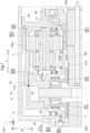
- FIG. 1 a vehicle drive system 100 according to a second embodiment will be described with reference to FIGS. 4 to 6.
- FIG. the configuration of the case 9 and the configuration of the output differential gear mechanism 5 are different from those of the first embodiment. Differences from the first embodiment will be mainly described below. Note that points that are not particularly described are the same as those in the first embodiment.
- the case 9 does not have a cover portion 95 in this embodiment. Therefore, in this embodiment, the fifth bearing B5 that supports the second output member 3 with respect to the cover portion 95 is not provided.
- the output differential gear mechanism 5 includes a differential case 51, a shaft member 52, a pinion gear 53, and a pair of side gears 54.
- the differential case 51 is formed to accommodate a pinion gear 53 and a pair of side gears 54 .
- the differential case 51 is connected to rotate integrally with the fourth rotating element E4 of the planetary gear mechanism 4 . That is, in this embodiment, the differential case 51 is the input element Ei.
- the shaft member 52 is arranged so as to extend along the radial direction R.
- the shaft member 52 is supported by the differential case 51 so as to rotate together with the differential case 51 .
- a plurality of shaft members 52 are distributed in the circumferential direction C along the radial direction R (for example, when viewed in the axial direction L, the four shaft members 52 are arranged in a cross shape). configured).
- the pinion gear 53 is rotatably supported by the shaft member 52 .
- the pinion gear 53 is configured to rotate (rotate) around the shaft member 52 and rotate (revolve) around the rotation axis of the differential case 51 (see one-dot chain line in FIG. 6).
- a pinion gear 53 is attached to each of the plurality of shaft members 52 distributed in the circumferential direction C. As shown in FIG. Note that the pinion gear 53 corresponds to a "first bevel gear".
- the pair of side gears 54 are arranged on both sides of the shaft member 52 in the axial direction L.
- a pair of side gears 54 mesh with the pinion gear 53 .
- the side gear 54 corresponds to a "second bevel gear”.
- first side gear 541 the side gear 54 on the first side L1 in the axial direction
- second side gear 542 the side gear 54 on the second side L2 in the axial direction
- the first side gear 541 is connected via the first output member 2 so as to rotate integrally with the first drive shaft DS1 drivingly connected to the first wheel W1.
- the first output member 2 is arranged to extend from the first side gear 541 to the axial first side L1.
- the first output member 2 is rotatably supported relative to the differential case 51 via an eighth bearing B8.
- the eighth bearing B8 is a slide bearing.
- the first output member 2 is formed in a tubular shape having an axial center along the axial direction L. As shown in FIG. A first drive shaft DS1 is inserted radially inward R1 from the first output member 2 from the first side L1 in the axial direction, and they are connected to each other by spline engagement.
- the second side gear 542 is integrated with the second drive shaft DS2 drivingly connected to the second wheel W2 via the output shaft 32 and the connecting member 31. connected for rotation.
- the output shaft 32 is inserted from the axial second side L2 inside the second side gear 542 in the radial direction R, and they are connected to each other by spline engagement.
- the connecting member 31 and the output shaft 32 are integrally formed.
- the output differential gear mechanism 5 includes the differential case 51 and the shaft member supported by the differential case 51 and extending along the radial direction R. 52, a pinion gear 53 housed in a differential case 51 and rotatably supported by a shaft member 52, and a pair of gears housed in the differential case 51 and engaged with the pinion gear 53 on both sides of the shaft member 52 in the axial direction L. and a side gear 54 of A differential case 51 is the input element Ei.
- the output differential gear mechanism 5 can be a bevel gear type differential gear mechanism. Since the differential case 51 housing the pinion gear 53 and the side gear 54 is the input element Ei connected to the fourth rotating element E4, the freedom of the connection structure between the planetary gear mechanism 4 and the output differential gear mechanism 5 It is easy to secure a high degree.
- the differential case 51 includes a first member 511 and a second member 512 in this embodiment.
- the first member 511 and the second member 512 are configured to be joined in the axial direction L to each other.
- the first member 511 is arranged on the first side L1 in the axial direction with respect to the shaft member 52
- the second member 512 is arranged on the second side L2 in the axial direction with respect to the shaft member 52.
- the first member 511 and the second member 512 support the shaft member 52 so as to sandwich the shaft member 52 in the axial direction L.
- the cylindrical member 10 is not provided in this embodiment. 4, the parking gear 6, the first member 511, and the second member 512 are fastened together in the axial direction L by bolts 50.
- the parking gear 6 in a state where the parking gear 6 is in contact with the first member 511 from the axial direction first side L1, the parking gear 6 is located in a region in the circumferential direction C of the differential case 51 where the shaft member 52 does not exist. , the first member 511, and the second member 512 from the axial direction first side L1.
- the vehicle drive device 100 further includes the parking gear 6 and the parking lock mechanism 7 selectively engaged with the parking gear 6,
- the differential case 51 includes a first member 511 and a second member 512 that are joined together in the axial direction L, The parking gear 6 , the first member 511 and the second member 512 are fastened together in the axial direction L by bolts 50 .
- the differential case 51 includes a first member 511 and a second member 512 that are joined together in the axial direction L. As shown in FIG. Accordingly, the work of assembling the shaft member 52, the pinion gear 53, and the side gear 54 to the differential case 51 can be easily performed. Moreover, according to this configuration, the parking gear 6 , the first member 511 and the second member 512 are fastened together in the axial direction L by the bolt 50 . As a result, compared to a configuration in which separate connecting members are used to connect the parking gear 6 to the differential case 51 and to connect the first member 511 and the second member 512, the vehicle drive device 100 is The number of parts can be reduced.
- the differential case 51 as the input element Ei of the output differential gear mechanism 5 is connected to the first side wall portion 92 of the case 9 via the third bearing B3. It is rotatably supported.
- the third bearing B3 includes a radial bearing B31 and a thrust bearing B32.
- the first side wall portion 92 corresponds to a "second support wall portion" arranged on the first side L1 in the axial direction from the differential gear mechanism 5 for output.
- the radial bearing B31 is arranged between the first member 511 and the first side wall portion 92 in the radial direction R.
- the radial bearing B31 supports the first member 511 in the radial direction R.
- the radial bearing B31 is arranged on the first side L1 in the axial direction with respect to the plurality of gears (here, the plurality of pinion gears 53 and the pair of side gears 54) forming the output differential gear mechanism 5.
- the radial bearing B31 is a slide bearing or a needle roller bearing.
- the radial bearing B31 is a sliding bearing.
- the radial bearing B31 is arranged on the first side L1 in the axial direction with respect to the plurality of gears constituting the output differential gear mechanism 5, and is a "second support bearing" that rotatably supports the input element Ei. corresponds to
- the thrust bearing B32 is arranged between the first member 511 and the first side wall portion 92 in the axial direction L.
- the thrust bearing B32 supports the first member 511 in the axial direction L.
- the thrust bearing B32 is arranged on the first side L1 in the axial direction with respect to the plurality of gears (here, the plurality of pinion gears 53 and the pair of side gears 54) that constitute the output differential gear mechanism 5.
- the thrust bearing B32 is arranged on the second axial side L2 and radially outward R2 with respect to the radial bearing B31.
- the thrust bearing B32 is a needle roller bearing.
- the differential case 51 is rotatably supported by the partition wall portion 94 of the case 9 via the sixth bearing B6 and the seventh bearing B7.
- the sixth bearing B6 is arranged between the second member 512 and a portion of the first carrier CR1 located on the axial first side L1 with respect to the second pinion gear PG2 in the axial direction L.
- the seventh bearing B7 is arranged between a portion of the first carrier CR1 located on the second side L2 in the axial direction with respect to the first pinion gear PG1 and the partition wall portion 94 in the axial direction L.
- the second member 512 is supported in the axial direction L with respect to the partition wall portion 94 via the sixth bearing B6 and the seventh bearing B7.
- each of the sixth bearing B6 and the seventh bearing B7 is a needle roller bearing.
- the differential case 51 is supported in the radial direction R by the radial bearing B31, and is supported in the axial direction L by the thrust bearing B32, the sixth bearing B6, and the seventh bearing B7. . That is, in the present embodiment, the bearing that supports the output differential gear mechanism 5 in the radial direction R is only the radial bearing B31.
- the planetary gear mechanism 4 is arranged on the first side L1 in the axial direction with respect to the rotor 12,
- the output differential gear mechanism 5 is arranged on the first side L1 in the axial direction with respect to the planetary gear mechanism 4,
- the input element Ei of the output differential gear mechanism 5 is connected via a radial bearing B31 as a second support bearing arranged on the first side L1 in the axial direction with respect to the plurality of gears forming the output differential gear mechanism 5. and is supported in the radial direction R with respect to the case 9 .
- the input gear of the output differential gear mechanism 5 is provided by the radial bearing B31 as the second support bearing.
- Element Ei can be supported in radial direction R.
- the aligning action (self-aligning action) of the planetary gear mechanism 4 is used to The input element Ei of the output differential gear mechanism 5 can be supported in the radial direction R.
- the input element Ei of the output differential gear mechanism 5 is shifted in the radial direction R only by the radial bearing B31 arranged on the first side L1 in the axial direction with respect to the gears constituting the output differential gear mechanism 5. It is possible to realize a configuration supported by Therefore, compared to a configuration in which the input element Ei is supported in the radial direction R by a plurality of bearings arranged on both sides in the axial direction L with respect to the plurality of gears constituting the output differential gear mechanism 5, the vehicle drive mechanism 5 It is easy to reduce the size and cost of the device 100 .
- the case 9 includes a first side wall portion 92 as a second support wall portion arranged on the first side L1 in the axial direction from the output differential gear mechanism 5,
- the input element Ei is supported in the radial direction R by a slide bearing or needle roller bearing disposed between the input element Ei and the first side wall portion 92 in the radial direction R. It is supported in the axial direction L by a thrust bearing B32 arranged between the side wall portion 92 and the axial direction L.
- the size of the vehicle drive device 100 is suppressed while supporting the input element Ei. A large degree of rigidity can be ensured.
- the differential case 51 as the input element Ei of the output differential gear mechanism 5 has a connecting portion 513 .
- the connecting portion 513 is formed to protrude from the second member 512 toward the radially outer side R2.
- the connecting portion 513 is configured integrally with the second ring gear RG2.
- integrally constructed includes that a plurality of elements are constructed of the same member and that a plurality of elements are inseparably connected by welding or the like.
- connected so as to rotate integrally includes that a plurality of elements are separably connected such as by spline engagement.
- the differential case 51 as the input element Ei of the output differential gear mechanism 5 has a fitting outer peripheral surface 51a facing radially outward R2.
- the second ring gear RG2 has a fitting inner peripheral surface 4a facing radially inward R1.
- the fitting inner peripheral surface 4a and the fitting outer peripheral surface 51a are fitted to each other so as to be in contact with each other in the radial direction R.
- a fitting outer peripheral surface 51 a is formed on the outer peripheral surface of the connecting portion 513 of the differential case 51 .
- a fitting inner peripheral surface 4a is formed on the inner peripheral surface of a portion of the second ring gear RG2 that protrudes from the toothed portion toward the first side L1 in the axial direction.
- the second ring gear RG2 and the input element Ei are fixed to each other by welding while the fitting inner peripheral surface 4a and the fitting outer peripheral surface 51a are fitted to each other.
- the coupling portion 513 of the differential case 51 is fitted to the second ring gear RG2 from the first side L1 in the axial direction, and the coupling portion 513 and the second ring gear RG2 are connected to each other in the axial direction. It is welded from one side L1.
- the second ring gear RG2 has the fitting inner peripheral surface 4a facing the radially inner side R1
- the input element Ei has a fitting outer peripheral surface 51a facing the radially outer side R2
- the second ring gear RG2 and the input element Ei are fixed to each other by welding in a state in which the fitting inner peripheral surface 4a and the fitting outer peripheral surface 51a are in contact with each other in the radial direction R. As shown in FIG.
- the first pinion gear PG1 and the second pinion gear PG2 are helical gears.
- the direction of the thrust load received by the first pinion gear PG1 from the first sun gear SG1 and the direction of the thrust load received by the second pinion gear PG2 from the second ring gear RG2 are the same as the direction of the thrust load received by the first pinion gear PG1 from the first ring gear RG1.
- the sum of the magnitude of the thrust load that the first pinion gear PG1 receives from the first sun gear SG1 and the magnitude of the thrust load that the second pinion gear PG2 receives from the second ring gear RG2 is
- the helical directions of the first pinion gear PG1 and the second pinion gear PG2 are set so as to be equal to or close to the magnitude of the thrust load received from RG1.
- the resultant force of the thrust loads from the first sun gear SG1, the first ring gear RG1, and the second ring gear RG2 acting on the first pinion gear PG1 and the second pinion gear PG2 that rotate integrally with each other is zero or a value close to zero.
- the helical directions of the first pinion gear PG1 and the second pinion gear PG2 are set so that
- the "helical direction" of each pinion gear refers to the direction of the torsion angle (twisting direction) of the teeth of each pinion gear.
- the black arrow shown on the first pinion gear PG1 adjacent to the first sun gear SG1 indicates the direction of the thrust load that the first pinion gear PG1 receives from the first sun gear SG1.
- a black arrow shown on the first pinion gear PG1 adjacent to the first ring gear RG1 indicates the direction of the thrust load that the first pinion gear PG1 receives from the first ring gear RG1.
- a black arrow shown on the second pinion gear PG2 adjacent to the second ring gear RG2 indicates the direction of the thrust load that the second pinion gear PG2 receives from the second ring gear RG2.
- the thrust load that the first pinion gear PG1 receives from the first sun gear SG1, the thrust load that the second pinion gear PG2 receives from the second ring gear RG2, and the thrust load that the first pinion gear PG1 receives from the first ring gear RG1. can cancel each other out.
- This prevents an excessive thrust load from acting on the bearings (here, the sixth bearing B6 and the seventh bearing B7) that support the first carrier CR1 that rotatably supports the first pinion gear PG1 and the second pinion gear PG2. can be avoided.
- the eighth bearing B8 is not provided in this embodiment. That is, in this embodiment, the differential case 51 is not supported by the first output member 2, but is supported by the first side wall portion 92 of the case 9 via the radial bearing B31.
- the radial bearing B31 is a needle roller bearing. A gap is formed between the first member 511 of the differential case 51 and the first output member 2 in the radial direction R.
- the differential case 51 has a differential case subject portion 514 .
- the differential case target portion 514 corresponds to "a portion on the second side L2 in the axial direction with respect to the central position in the axial direction L of the output differential gear mechanism 5 in the differential case 51".
- the "center position in the axial direction L of the output differential gear mechanism 5" is the position of the axial center of the shaft member 52 in the axial direction L.
- the differential case target portion 514 is formed to protrude from the second member 512 of the differential case 51 toward the axial second side L2. Further, the differential case target portion 514 is rotatably supported relative to the second output member 3 via the ninth bearing B9.
- the second output member 3 is arranged so as to penetrate the differential case target portion 514 in the axial direction L on the radial inner side R1.
- a ninth bearing B ⁇ b>9 is arranged between the inner peripheral surface of the differential case target portion 514 and the outer peripheral surface of the second output member 3 .
- the output shaft 32 of the second output member 3 is arranged so as to pass through the differential case target portion 514 in the axial direction L on the radial inner side R1.
- a ninth bearing B ⁇ b>9 is arranged between the inner peripheral surface of the differential case target portion 514 and the outer peripheral surface of the output shaft 32 .
- the ninth bearing B9 corresponds to a "third support bearing".
- the ninth bearing B9 may not be provided.
- the first output member 2 is arranged on the first side L1 in the axial direction with respect to the second output member 3, A portion on the second side L2 in the axial direction with respect to the central position in the axial direction L of the output differential gear mechanism 5 in the differential case 51 is defined as a differential case target portion 514,
- the second output member 3 is arranged so as to penetrate the differential case target portion 514 in the radial direction inner side R1 in the axial direction L,
- a ninth bearing B ⁇ b>9 as a third support bearing is arranged between the inner peripheral surface of the differential case target portion 514 and the outer peripheral surface of the second output member 3 .
- the differential case target portion 514 which is the portion on the second side L2 in the axial direction with respect to the central position in the axial direction L of the output differential gear mechanism 5 in the differential case 51, is the ninth bearing B9. Supported by Thereby, the support accuracy of the differential case 51 can be improved.
- the parking gear 6 is arranged so as to overlap the output differential gear mechanism 5 when viewed in the radial direction R, as an example.
- the parking gear 6 may be arranged on one side in the axial direction L of the output differential gear mechanism 5 .
- the configuration in which the second ring gear RG2, the third ring gear RG3, and the parking gear 6 are formed on the same tubular member 10 has been described as an example. However, without being limited to such a configuration, they may be configured by being divided into a plurality of members.
- the second ring gear RG2, the third ring gear RG3, and the parking gear 6 may be formed as separate members and connected to rotate integrally with each other.
- the arrangement area of the second oil passage 82 in the circumferential direction C and the arrangement area of the terminal portion 14 in the circumferential direction C do not overlap, and the axial direction of the second oil passage 82 A configuration in which the arrangement area in L overlaps with the arrangement area in the axial direction L of the terminal portion 14 has been described as an example.
- the second oil passage 82 and the terminal portion 14 may be displaced from each other in the axial direction L without being limited to such a configuration.
- the differential case 51 is rotatably supported relative to the first output member 2 via the eighth bearing B8, and the case 9 is supported via the radial bearing B31.
- the configuration has been described as an example in which it is rotatably supported with respect to.
- the first output member 2 is rotatably supported with respect to the case 9 via the radial bearing B31
- the differential case 51 is supported via the eighth bearing B8.
- a configuration in which the differential case 51 is supported so as to be relatively rotatable with respect to the first output member 2 that is, a configuration in which the differential case 51 is indirectly supported by the case 9 via the first output member 2 may be used.
- the differential case 51 of the output differential gear mechanism 5 includes the first member 511 and the second member 512 joined together in the axial direction L, and the parking gear 6, the first member 511, and the second member 512 are fastened together in the axial direction L by the bolt 50, as an example.
- the connection of the parking gear 6 to the differential case 51 and the connection of the first member 511 and the second member 512 are performed using separate connection members. It's okay to be.
- the differential case 51 may be configured by one member without the first member 511 and the second member 512 .
- the input element Ei is radially moved by the radial bearing B31, which is a sliding bearing, disposed between the input element Ei and the first side wall portion 92 in the radial direction R.
- the radial bearing B31 which is a sliding bearing
- a configuration in which the input element Ei and the first side wall portion 92 are supported in the axial direction L by the thrust bearing B32 arranged between the input element Ei and the first side wall portion 92 in the axial direction L has been described as an example.
- the input element Ei may be supported in both the radial direction R and the axial direction L by ball bearings, for example.
- the vehicle drive device (100) includes: a rotating electric machine (1) having a rotor (12); a first output member (2) drivingly connected to the first wheel (W1); a second output member (3) drivingly connected to the second wheel (W2); a planetary gear mechanism (4) that slows down the rotation of the rotor (12); An output that comprises an input element (Ei) and distributes rotation transmitted from the planetary gear mechanism (4) to the input element (Ei) to the first output member (2) and the second output member (3) a differential gear mechanism (5) for A vehicle drive device (100) comprising a case (9) housing the rotating electric machine (1), the planetary gear mechanism (4), and the output differential gear mechanism (5), The rotating electrical machine (1), the first output member (2), the second output member (3), the planetary gear mechanism (4), and the output differential gear mechanism (5) are arranged coaxially.
- the planetary gear mechanism (4) comprises a first rotating element (E1), a second rotating element (E2), a third rotating element (E3), and a fourth rotating element (E4), and the first rotating element ( E1), the second rotating element (E2), the third rotating element (E3), and the fourth rotating element (E4) are configured so that their rotation speeds are in the order described,
- the first rotating element (E1) is a first sun gear (SG1) coupled to rotate integrally with the rotor (12)
- the third rotating element (E3) is a first ring gear (RG1) connected to the case (9)
- the fourth rotating element (E4) is a second ring gear (RG2) coupled to rotate integrally with the input element (Ei)
- the second rotating element (E2) is a first carrier (CR1) that rotatably supports a first pinion gear (PG1) and a second pinion gear (PG2) that rotate integrally with each other,
- the first pinion gear (PG1) meshes with the first sun gear (SG1) and the first ring
- the first rotating element (E1) of the planetary gear mechanism (4) is connected to the rotor (12).
- the third rotating element (E3) of the planetary gear mechanism (4) is connected to the case (9), and the fourth rotating element (E4) of the planetary gear mechanism (4) is connected to the output differential gear mechanism (5). It is linked to the input elements (Ei).
- each of the third rotating element (E3) and the fourth rotating element (E4) of the planetary gear mechanism (4) is a ring gear.
- the fourth rotating element (E4) connected to the input element (Ei) of the output differential gear mechanism (5) is a ring gear. This reduces the radial dimension (R) of the planetary gear mechanism (4) compared to a configuration in which the rotating element connected to the input element (Ei) of the output differential gear mechanism (5) is a sun gear or a carrier. It is easy to dispose the planetary gear mechanism (4) close to the output differential gear mechanism (5) in the axial direction (L) while keeping the size small.
- the third rotating element (E3) connected to the case (9) is a ring gear.
- the first sun gear (SG1) as the first rotating element (E1) of the planetary gear mechanism (4) is diametrically opposed to the case (9) via the first support bearing (B1). It is supported in direction (R).
- the second ring gear (RG2) as the fourth rotating element (E4) of the planetary gear mechanism (4) and the input element (Ei) of the output differential gear mechanism (5) are arranged in the radial direction (R).
- the input element (Ei) of the output differential gear mechanism (5) can be supported in the radial direction (R) by utilizing the aligning action (self-aligning action) of the planetary gear mechanism (4). can.
- the output differential gear mechanism ( 5) can be properly supported. Therefore, it is easy to reduce the size and cost of the vehicle drive device (100).
- the direction along the rotation axis of the rotor (12) is defined as the axial direction (L)
- one side of the axial direction (L) is defined as the axial direction first side (L1)
- the axial direction (L) With the other side as the axial second side (L2)
- the planetary gear mechanism (4) is arranged on the axial first side (L1) with respect to the rotor (12)
- the output differential gear mechanism (5) is arranged on the axial first side (L1) with respect to the planetary gear mechanism (4)
- the input element (Ei) is preferably supported in the radial direction (R) with respect to the case (9).
- the output differential gear mechanism ( The input elements (Ei) of 5) can be supported radially (R). Further, on the second axial side (L2) with respect to the plurality of gears constituting the output differential gear mechanism (5), as described above, the planetary gear mechanism (4) has an aligning action (self-aligning action) can be used to support the input element (Ei) of the output differential gear mechanism (5) in the radial direction (R). As a result, only the second support bearing (B31) arranged on the first side (L1) in the axial direction with respect to the plurality of gears constituting the output differential gear mechanism (5) can support the output differential gear mechanism (5).
- a configuration in which the input element (Ei) of 5) is supported in the radial direction (R) can be realized. Therefore, the input element (Ei) is supported in the radial direction (R) by a plurality of bearings arranged on both sides in the axial direction (L) with respect to the gears that constitute the output differential gear mechanism (5). It is easier to reduce the size and cost of the vehicle drive device (100) compared to the configuration.
- the output differential gear mechanism (5) includes a differential case (51) and a shaft member supported by the differential case (51) and extending along the radial direction (R). (52); a first bevel gear (53) housed in the differential case (51) and rotatably supported by the shaft member (52); a pair of second bevel gears (54) meshing with the first bevel gears (53) on both sides in the axial direction (L) with respect to the shaft member (52);
- said differential case (51) is said input element (Ei).
- the output differential gear mechanism (5) can be a bevel gear type differential gear mechanism. Since the differential case (51) housing the pinion gear (53) and the side gear (54) is the input element (Ei) connected to the fourth rotating element (E4), the planetary gear mechanism (4) and the output It is easy to ensure a high degree of freedom in the connection structure with the differential gear mechanism (5).
- the output differential gear mechanism (5) includes a differential case (51), the shaft member (52), the first bevel gear (53), and the pair of second bevel gears (54)
- the first output member (2) is arranged on the axial first side (L1) with respect to the second output member (3)
- a portion of the differential case (51) on the axial second side (L2) with respect to the center position of the output differential gear mechanism (5) in the axial direction (L) is a differential case target portion (514).
- the second output member (3) is arranged so as to pass through the radial direction (R) inner side (R1) in the axial direction (L) with respect to the differential case target portion (514),
- a third support bearing (B9) is preferably arranged between the inner peripheral surface of the differential case target portion (514) and the outer peripheral surface of the second output member (3).
- the differential case target is the portion on the second side (L2) in the axial direction with respect to the central position in the axial direction (L) of the output differential gear mechanism (5) in the differential case (51).
- Part (514) is supported by the third support bearing (B9). Thereby, the support accuracy of the differential case (51) can be improved.
- the output differential gear mechanism (5) is a planetary gear mechanism including a second sun gear (SG2), a second carrier (CR2), and a third ring gear (RG3),
- the second sun gear (SG2) is connected to rotate integrally with the first output member (2)
- the second carrier (CR2) is coupled to rotate integrally with the second output member (3);
- the third ring gear (RG3) is preferably the input element (Ei).
- the second output member ( 3) can be supported in the radial direction (R).
- the case (9) includes a first support wall (94) disposed between the rotating electric machine (1) and the planetary gear mechanism (4) in the axial direction (L),
- the first support bearing (B1) is supported by the first support wall (94) to support the first sun gear (SG1) in the radial direction (R) and the rotor (12) in the radial direction.
- (R) is preferably configured to perform the support.
- the second ring gear (RG2) has a fitting inner peripheral surface (4a) facing the inner side (R1) in the radial direction (R),
- the input element (Ei) has a fitting outer peripheral surface (51a) facing the outside (R2) in the radial direction (R),
- the second ring gear (RG2) and the input element (Ei ) are fixed to each other by welding.
- first pinion gear (PG1) and the second pinion gear (PG2) are helical gears,
- the direction of the thrust load received by the first pinion gear (PG1) from the first sun gear (SG1) and the direction of the thrust load received by the second pinion gear (PG2) from the second ring gear (RG2) It is preferable that the direction of the thrust load applied to the pinion gear (PG1) from the first ring gear (RG1) is opposite to that of the pinion gear (PG1).
- the thrust load that the first pinion gear (PG1) receives from the first sun gear (SG1), the thrust load that the second pinion gear (PG2) receives from the second ring gear (RG2), and the thrust load that the first pinion gear (PG1) receives and the thrust load received from the first ring gear (RG1) can cancel each other out.
- a direction along the rotation axis of the rotor (12) is defined as an axial direction (L), one side of the axial direction (L) is defined as an axial direction first side (L1), and the other side of the axial direction (L) is defined as an axial direction first side (L1). side as the axial second side (L2),
- the case (9) includes a second support wall (92) arranged on the first side (L1) in the axial direction from the output differential gear mechanism (5),
- the input element (Ei) is arranged between the input element (Ei) and the second support wall (92) in the radial direction (R) by means of a slide bearing or a needle roller bearing. R) and is supported in the axial direction (L ) is preferably supported.
- the technology according to the present disclosure can be used in a vehicle drive device that includes a rotating electric machine and a planetary gear mechanism.
Abstract
A first rotating element (E1) is a first sun gear (SG1) that rotates integrally with a rotor (12), a third rotating element (E3) is a first ring gear (RG1) that is coupled to a case (9), a fourth rotating element (E4) is a second ring gear (RG2) that rotates integrally with an input element (Ei), and a second rotating element (E2) is a first carrier (CR1) that rotatably supports a first pinion gear (PG1) and a second pinion gear (PG2) which rotate integrally with one another, wherein: the first pinion gear (PG1) meshes with the first sun gear (SG1) and the first ring gear (RG1); the second pinion gear (PG2) has a smaller diameter than the first pinion gear (PG1) and meshes with the second ring gear (RG2); the first sun gear (SG1) is supported in a radial direction (R) with respect to the case (9) by means of a first support bearing (B1); and the second ring gear (RG2) and the input element (Ei) are coupled such that relative displacement in the radial direction (R) is restricted.
Description
本発明は、回転電機及び遊星歯車機構を備えた車両用駆動装置に関する。
The present invention relates to a vehicle drive device that includes a rotating electric machine and a planetary gear mechanism.
このような車両用駆動装置の一例が、下記の特許文献1及び特許文献2に開示されている。以下、背景技術の説明では、参照する特許文献における符号を括弧内に引用する。
An example of such a vehicle driving device is disclosed in Patent Document 1 and Patent Document 2 below. In the following description of the background art, reference numerals in patent documents to be referenced are quoted in parentheses.
特許文献1の車両用駆動装置(1)の遊星歯車機構(4)は、サンギヤ(41)と、リングギヤ(42)と、キャリヤ(6,7)と、を備えている。サンギヤ(41)は、回転電機(2)のロータ(21)と一体的に回転するように連結されている。リングギヤ(42)は、ケース(10)に固定されている。キャリヤ(6,7)は、互いに一体的に回転するように連結された第1ピニオンギヤ(431)及び第2ピニオンギヤ(432)を回転自在に支持している。第1ピニオンギヤ(431)は、サンギヤ(41)に噛み合っている。第2ピニオンギヤ(432)は、第1ピニオンギヤ(431)よりも小径であり、リングギヤ(42)に噛み合っている。また、キャリヤ(6,7)は、出力用差動歯車機構(5)の差動ケース(50)と一体的に回転するように連結されている。こうして、遊星歯車機構(4)は、ロータ(21)の回転を減速し、出力用差動歯車機構(5)に伝達する。
The planetary gear mechanism (4) of the vehicle drive device (1) of Patent Document 1 includes a sun gear (41), a ring gear (42), and carriers (6, 7). The sun gear (41) is coupled to rotate integrally with the rotor (21) of the rotating electric machine (2). A ring gear (42) is fixed to the case (10). The carriers (6, 7) rotatably support a first pinion gear (431) and a second pinion gear (432) which are connected to rotate integrally with each other. The first pinion gear (431) meshes with the sun gear (41). The second pinion gear (432) has a smaller diameter than the first pinion gear (431) and meshes with the ring gear (42). Further, the carriers (6, 7) are connected to rotate integrally with the differential case (50) of the output differential gear mechanism (5). Thus, the planetary gear mechanism (4) decelerates the rotation of the rotor (21) and transmits it to the output differential gear mechanism (5).
また、特許文献2の車両用駆動装置の遊星歯車機構(3)は、サンギヤ(S1)と、キャリヤ(C)と、第1リングギヤ(R1)と、第2リングギヤ(R2)と、を備えている(特許文献2の図4参照)。サンギヤ(S1)は、回転電機(2)のロータと一体的に回転するように連結されている。キャリヤ(C)は、互いに一体的に回転するように連結された第1ピニオンギヤ(P1)及び第2ピニオンギヤ(P2)を回転自在に支持している。第1ピニオンギヤ(P1)は、サンギヤ(S1)及び第1リングギヤ(R1)に噛み合っている。第2ピニオンギヤ(P2)は、第1ピニオンギヤ(P1)よりも小径であり、第2リングギヤ(R2)に噛み合っている。第1リングギヤ(R1)は、ケース(1)に固定されている。第2リングギヤ(R2)は、傘歯車式の差動歯車機構である出力用差動歯車機構(4)に連結されている。こうして、遊星歯車機構(3)は、回転電機(2)のロータの回転を減速し、出力用差動歯車機構(4)に伝達する。
Further, the planetary gear mechanism (3) of the vehicle drive device of Patent Document 2 includes a sun gear (S1), a carrier (C), a first ring gear (R1), and a second ring gear (R2). (see FIG. 4 of Patent Document 2). The sun gear (S1) is coupled to rotate integrally with the rotor of the rotating electric machine (2). The carrier (C) rotatably supports a first pinion gear (P1) and a second pinion gear (P2) which are connected to rotate integrally with each other. The first pinion gear (P1) meshes with the sun gear (S1) and the first ring gear (R1). The second pinion gear (P2) has a smaller diameter than the first pinion gear (P1) and meshes with the second ring gear (R2). A first ring gear (R1) is fixed to the case (1). The second ring gear (R2) is connected to an output differential gear mechanism (4), which is a bevel gear type differential gear mechanism. In this way, the planetary gear mechanism (3) decelerates the rotation of the rotor of the rotating electric machine (2) and transmits it to the output differential gear mechanism (4).
特許文献1の車両用駆動装置(1)では、遊星歯車機構(4)の入力要素がサンギヤ(41)であり、遊星歯車機構(4)の出力要素がキャリヤ(6,7)である。このような構成では、遊星歯車機構(4)の径方向の寸法を大きく確保しなければ、遊星歯車機構(4)の減速比を大きくすることが困難であった。
In the vehicle drive device (1) of Patent Document 1, the sun gear (41) is the input element of the planetary gear mechanism (4), and the carrier (6, 7) is the output element of the planetary gear mechanism (4). With such a configuration, it is difficult to increase the reduction ratio of the planetary gear mechanism (4) unless a large radial dimension of the planetary gear mechanism (4) is ensured.
また、特許文献1の車両用駆動装置(1)では、傘歯車式の出力用差動歯車機構(5)に対して径方向の外側に、遊星歯車機構(4)が配置されている。そのため、車両用駆動装置(1)の軸方向の寸法が小さく抑えられている。しかし、上述したように、第1ピニオンギヤ(431)及び第2ピニオンギヤ(432)を支持するキャリヤ(6,7)が、出力用差動歯車機構(5)の差動ケース(50)と一体的に回転するように連結されている。そのため、出力用差動歯車機構(5)に対して径方向の外側に遊星歯車機構(4)が配置された構成とした場合、車両用駆動装置(1)が径方向に大型化し易かった。
In addition, in the vehicle drive device (1) of Patent Document 1, the planetary gear mechanism (4) is arranged radially outside the bevel gear type output differential gear mechanism (5). Therefore, the axial dimension of the vehicle drive device (1) is kept small. However, as described above, the carriers (6, 7) supporting the first pinion gear (431) and the second pinion gear (432) are integrated with the differential case (50) of the output differential gear mechanism (5). connected for rotation. Therefore, when the planetary gear mechanism (4) is arranged radially outside the output differential gear mechanism (5), the vehicle drive device (1) tends to be radially large.
一方、特許文献2の車両用駆動装置の遊星歯車機構(3)は、径方向の寸法を小さく抑えつつ、減速比を大きく確保し易い構成となっている。ところで、出力用差動歯車機構(4)の差動ケース(DC)は、出力用差動歯車機構(4)を構成する複数のギヤ(DP1,DP2,DSI1,DSI2)に対して軸方向の両側でケース(1)に対して支持されることが一般的である。特許文献2の車両用駆動装置では、このような出力用差動歯車機構(4)の支持構造について記載されていない。
On the other hand, the planetary gear mechanism (3) of the vehicle drive device of Patent Document 2 has a configuration in which it is easy to secure a large reduction ratio while keeping the radial dimension small. By the way, the differential case (DC) of the output differential gear mechanism (4) is arranged axially with respect to the plurality of gears (DP1, DP2, DSI1, DSI2) constituting the output differential gear mechanism (4). It is generally supported against the case (1) on both sides. The vehicle drive device of Patent Document 2 does not describe a support structure for such an output differential gear mechanism (4).
そこで、減速用の遊星歯車機構及び出力用差動歯車機構を備えた構成において、当該遊星歯車機構の減速比を大きく確保できると共に出力用差動歯車機構を適切に支持できるようにしつつ、小型化を図り易い車両用駆動装置の実現が望まれる。
Therefore, in a configuration including a planetary gear mechanism for reduction and a differential gear mechanism for output, it is possible to ensure a large reduction ratio of the planetary gear mechanism and to appropriately support the differential gear mechanism for output, while reducing the size. It is desired to realize a vehicle drive system that can easily achieve
上記に鑑みた、車両用駆動装置の特徴構成は、
ロータを備えた回転電機と、
第1車輪に駆動連結される第1出力部材と、
第2車輪に駆動連結される第2出力部材と、
前記ロータの回転を減速する遊星歯車機構と、
入力要素を備え、前記遊星歯車機構から前記入力要素に伝達された回転を前記第1出力部材と前記第2出力部材とに分配する出力用差動歯車機構と、
前記回転電機、前記遊星歯車機構、及び前記出力用差動歯車機構を収容するケースと、を備えた車両用駆動装置であって、
前記回転電機、前記第1出力部材、前記第2出力部材、前記遊星歯車機構、及び前記出力用差動歯車機構が、同軸上に配置され、
前記遊星歯車機構は、第1回転要素、第2回転要素、第3回転要素、及び第4回転要素を備え、前記第1回転要素、前記第2回転要素、前記第3回転要素、及び前記第4回転要素の回転速度の順が記載の順となるように構成され、
前記第1回転要素は、前記ロータと一体的に回転するように連結された第1サンギヤであり、
前記第3回転要素は、前記ケースに連結された第1リングギヤであり、
前記第4回転要素は、前記入力要素と一体的に回転するように連結された第2リングギヤであり、
前記第2回転要素は、互いに一体的に回転する第1ピニオンギヤと第2ピニオンギヤとを回転自在に支持する第1キャリヤであり、
前記第1ピニオンギヤは、前記第1サンギヤと前記第1リングギヤとに噛み合い、
前記第2ピニオンギヤは、前記第1ピニオンギヤよりも小径であり、前記第2リングギヤに噛み合い、
前記ロータの回転軸心に直交する方向を径方向として、
前記第1サンギヤは、第1支持軸受を介して前記ケースに対して前記径方向に支持され、
前記第2リングギヤと前記入力要素とは、前記径方向の相対移動が規制された状態で連結されている点にある。 In view of the above, the characteristic configuration of the vehicle drive system is as follows.
a rotating electric machine having a rotor;
a first output member drivingly connected to the first wheel;
a second output member drivingly connected to the second wheel;
a planetary gear mechanism that decelerates rotation of the rotor;
an output differential gear mechanism comprising an input element and distributing rotation transmitted from the planetary gear mechanism to the input element to the first output member and the second output member;
A vehicle drive device comprising: a case accommodating the rotating electric machine, the planetary gear mechanism, and the output differential gear mechanism,
the rotating electric machine, the first output member, the second output member, the planetary gear mechanism, and the output differential gear mechanism are coaxially arranged;
The planetary gear mechanism includes a first rotating element, a second rotating element, a third rotating element, and a fourth rotating element, and the first rotating element, the second rotating element, the third rotating element, and the fourth rotating element. 4 configured so that the order of rotational speed of the rotating elements is the order of description,
The first rotating element is a first sun gear coupled to rotate integrally with the rotor,
The third rotating element is a first ring gear connected to the case,
The fourth rotating element is a second ring gear coupled to rotate integrally with the input element,
The second rotating element is a first carrier that rotatably supports a first pinion gear and a second pinion gear that rotate integrally with each other,
the first pinion gear meshes with the first sun gear and the first ring gear;
the second pinion gear has a smaller diameter than the first pinion gear and meshes with the second ring gear;
With the direction orthogonal to the rotation axis of the rotor being the radial direction,
The first sun gear is supported in the radial direction with respect to the case via a first support bearing,
The second ring gear and the input element are connected in such a manner that relative movement in the radial direction is restricted.
この特徴構成によれば、遊星歯車機構の第1回転要素がロータに連結されている。そして、遊星歯車機構の第3回転要素がケースに連結され、遊星歯車機構の第4回転要素が出力用差動歯車機構の入力要素に連結されている。また、遊星歯車機構の第3回転要素及び第4回転要素のそれぞれが、リングギヤである。これにより、ロータの回転を減速して出力用差動歯車機構に伝達する減速機として機能する遊星歯車機構の減速比を大きく確保(例えば、17~22)し易い。
また、本特徴構成によれば、出力用差動歯車機構の入力要素に連結された第4回転要素が、リングギヤである。これにより、出力用差動歯車機構の入力要素に連結された回転要素がサンギヤ又はキャリヤである構成に比べて、遊星歯車機構の径方向の寸法を小さく抑えつつ、遊星歯車機構を出力用差動歯車機構に対して軸方向に近付けて配置し易い。
また、本特徴構成によれば、ケースに連結された第3回転要素が、リングギヤである。これにより、サンギヤ又はキャリヤがケースに連結される場合に必要となる、径方向に延在する支持部材等を省略可能な構成とし易い。したがって、車両用駆動装置の軸方向の寸法を小さく抑え易い。
また、本特徴構成によれば、遊星歯車機構の第1回転要素としての第1サンギヤが、第1支持軸受を介してケースに対して径方向に支持されている。そして、遊星歯車機構の第4回転要素としての第2リングギヤと、出力用差動歯車機構の入力要素とが、径方向の相対移動が規制された状態で連結されている。これにより、遊星歯車機構の調心作用(自動調心作用)を利用して、出力用差動歯車機構の入力要素を径方向に支持することができる。その結果、出力用差動歯車機構の入力要素をケースに対して径方向に支持する軸受等の部材を省略しつつ、出力用差動歯車機構を適切に支持することができる。したがって、車両用駆動装置の小型化及び低コスト化を図り易い。
以上のように、本特徴構成によれば、減速用の遊星歯車機構及び出力用差動歯車機構を備えた構成において、当該遊星歯車機構の減速比を大きく確保できると共に出力用差動歯車機構を適切に支持できるようにしつつ、車両用駆動装置の小型化を図り易い。 According to this characteristic configuration, the first rotating element of the planetary gear mechanism is connected to the rotor. The third rotating element of the planetary gear mechanism is connected to the case, and the fourth rotating element of the planetary gear mechanism is connected to the input element of the output differential gear mechanism. Also, each of the third rotating element and the fourth rotating element of the planetary gear mechanism is a ring gear. This makes it easy to secure a large reduction ratio (for example, 17 to 22) for the planetary gear mechanism that functions as a speed reducer that reduces the rotation of the rotor and transmits it to the output differential gear mechanism.
Further, according to this characteristic configuration, the fourth rotating element connected to the input element of the output differential gear mechanism is the ring gear. As a result, compared to a structure in which the rotating element connected to the input element of the differential gear mechanism for output is a sun gear or a carrier, the radial dimension of the planetary gear mechanism can be kept small, and the planetary gear mechanism can be used as the differential gear mechanism for output. It is easy to dispose close to the gear mechanism in the axial direction.
Further, according to this characteristic configuration, the third rotating element connected to the case is a ring gear. As a result, it is easy to provide a configuration in which a support member or the like extending in the radial direction, which is required when the sun gear or carrier is connected to the case, can be omitted. Therefore, it is easy to keep the axial dimension of the vehicle drive device small.
Further, according to this characteristic configuration, the first sun gear as the first rotating element of the planetary gear mechanism is radially supported by the case via the first support bearing. Then, the second ring gear as the fourth rotating element of the planetary gear mechanism and the input element of the output differential gear mechanism are connected in a state in which relative movement in the radial direction is restricted. Thereby, the input element of the output differential gear mechanism can be radially supported by utilizing the aligning action (self-aligning action) of the planetary gear mechanism. As a result, it is possible to appropriately support the output differential gear mechanism while omitting a member such as a bearing that radially supports the input element of the output differential gear mechanism with respect to the case. Therefore, it is easy to reduce the size and cost of the vehicle drive device.
As described above, according to this characteristic configuration, in a configuration including a planetary gear mechanism for speed reduction and a differential gear mechanism for output, a large reduction ratio can be secured for the planetary gear mechanism and the differential gear mechanism for output can be secured. It is easy to reduce the size of the vehicular drive device while appropriately supporting it.
1.第1の実施形態
以下では、第1の実施形態に係る車両用駆動装置100について、図1から図3を参照して説明する。図1及び図2に示すように、車両用駆動装置100は、ステータ11及びロータ12を備えた回転電機1と、第1車輪W1に駆動連結される第1出力部材2と、第2車輪W2に駆動連結される第2出力部材3と、遊星歯車機構4と、出力用差動歯車機構5と、ケース9と、を備えている。 1. First Embodiment Hereinafter, avehicle drive system 100 according to a first embodiment will be described with reference to FIGS. 1 to 3. FIG. As shown in FIGS. 1 and 2, the vehicle drive device 100 includes a rotating electric machine 1 having a stator 11 and a rotor 12, a first output member 2 drivingly connected to a first wheel W1, and a second wheel W2. , a planetary gear mechanism 4 , an output differential gear mechanism 5 , and a case 9 .
以下では、第1の実施形態に係る車両用駆動装置100について、図1から図3を参照して説明する。図1及び図2に示すように、車両用駆動装置100は、ステータ11及びロータ12を備えた回転電機1と、第1車輪W1に駆動連結される第1出力部材2と、第2車輪W2に駆動連結される第2出力部材3と、遊星歯車機構4と、出力用差動歯車機構5と、ケース9と、を備えている。 1. First Embodiment Hereinafter, a
ここで、本願において「駆動連結」とは、2つの回転要素が駆動力を伝達可能に連結された状態を指し、当該2つの回転要素が一体的に回転するように連結された状態、或いは当該2つの回転要素が1つ又は2つ以上の伝動部材を介して駆動力を伝達可能に連結された状態を含む。このような伝動部材としては、回転を同速で又は変速して伝達する各種の部材、例えば、軸、歯車機構、ベルト、チェーン等が含まれる。なお、伝動部材として、回転及び駆動力を選択的に伝達する係合装置、例えば、摩擦係合装置、噛み合い式係合装置等が含まれていても良い。
Here, in the present application, "driving connection" refers to a state in which two rotating elements are connected so as to be able to transmit a driving force, and the two rotating elements are connected so as to rotate integrally. It includes a state in which two rotating elements are connected so as to be able to transmit driving force via one or more transmission members. Such transmission members include various members that transmit rotation at the same speed or at different speeds, such as shafts, gear mechanisms, belts, and chains. The transmission member may include an engagement device for selectively transmitting rotation and driving force, such as a friction engagement device and a mesh type engagement device.
以下の説明では、ロータ12の回転軸心(図1における1点鎖線参照)に沿う方向を「軸方向L」とする。そして、軸方向Lの一方側を「軸方向第1側L1」とし、軸方向Lの他方側を「軸方向第2側L2」とする。また、ロータ12の回転軸心に直交する方向を「径方向R」とする。そして、径方向Rにおいて、ロータ12の回転軸心側を「径方向内側R1」とし、その反対側を「径方向外側R2」とする。また、ロータ12の回転軸心を周回する方向を「周方向C」とする。
In the following description, the direction along the rotation axis of the rotor 12 (see one-dot chain line in FIG. 1) is defined as "axial direction L". One side in the axial direction L is referred to as "first axial side L1", and the other side in the axial direction L is referred to as "second axial side L2". A direction orthogonal to the rotation axis of the rotor 12 is defined as a "radial direction R". In the radial direction R, the rotation axis side of the rotor 12 is defined as "radial inner side R1", and the opposite side is defined as "radial outer side R2". Also, the direction in which the rotor 12 rotates around the rotation axis is defined as "circumferential direction C".
回転電機1、第1出力部材2、第2出力部材3、遊星歯車機構4、及び出力用差動歯車機構5は、同軸上に配置されている。本実施形態では、出力用差動歯車機構5、遊星歯車機構4、及び回転電機1が、軸方向第1側L1から軸方向第2側L2に向けて、記載の順に配置されている。なお、図1に示す例では、第2出力部材3の一部は、径方向Rに沿う径方向視で回転電機1と重複するように配置されている。ここで、2つの要素の配置に関して、「特定方向視で重複する」とは、その視線方向に平行な仮想直線を当該仮想直線と直交する各方向に移動させた場合に、当該仮想直線が2つの要素の双方に交わる領域が少なくとも一部に存在することを指す。
The rotating electric machine 1, the first output member 2, the second output member 3, the planetary gear mechanism 4, and the output differential gear mechanism 5 are coaxially arranged. In this embodiment, the output differential gear mechanism 5, the planetary gear mechanism 4, and the rotating electric machine 1 are arranged in the order described from the first axial side L1 toward the second axial side L2. In addition, in the example shown in FIG. 1 , a part of the second output member 3 is arranged so as to overlap with the rotary electric machine 1 when viewed in the radial direction R. As shown in FIG. Here, regarding the arrangement of two elements, "overlapping in a particular direction view" means that when a virtual straight line parallel to the line-of-sight direction is moved in each direction orthogonal to the virtual straight line, the virtual straight line is two It refers to the existence of at least a part of an area that intersects two elements.
回転電機1、遊星歯車機構4、及び出力用差動歯車機構5は、ケース9に収容されている。本実施形態では、第1出力部材2及び第2出力部材3は、それらの一部がケース9の外部に露出した状態で、ケース9に収容されている。
The rotating electric machine 1, the planetary gear mechanism 4, and the output differential gear mechanism 5 are housed in a case 9. In the present embodiment, the first output member 2 and the second output member 3 are housed in the case 9 in a state where their parts are exposed to the outside of the case 9 .
図1に示すように、本実施形態では、ケース9は、周壁部91と、第1側壁部92と、第2側壁部93と、隔壁部94と、カバー部95と、を備えている。
As shown in FIG. 1, the case 9 includes a peripheral wall portion 91, a first side wall portion 92, a second side wall portion 93, a partition wall portion 94, and a cover portion 95 in this embodiment.
周壁部91は、回転電機1、第1出力部材2、第2出力部材3、遊星歯車機構4、及び出力用差動歯車機構5の径方向外側R2を覆う筒状に形成されている。第1側壁部92、第2側壁部93、及び隔壁部94のそれぞれは、径方向R及び周方向Cに延在するように形成されている。カバー部95は、第2側壁部93の一部を軸方向第2側L2から覆うように設けられている。本実施形態では、第1側壁部92は、出力用差動歯車機構5の軸方向第1側L1を覆うように形成されている。そして、第2側壁部93は、回転電機1の軸方向第2側L2を覆うように形成されている。また、隔壁部94は、回転電機1と遊星歯車機構4との軸方向Lの間に配置されている。また、カバー部95は、第2側壁部93に対して軸方向第2側L2から接合されている。本例では、第1側壁部92は、周壁部91の軸方向第1側L1の開口を塞ぐように、周壁部91と一体的に形成されている。また、第2側壁部93は、周壁部91の軸方向第2側L2の開口を塞ぐように、周壁部91と一体的に形成されている。なお、図1に示す例では、周壁部91は、軸方向Lにおける複数個所(ここでは、2箇所)で分割されている。そして、周壁部91の分割部は、互い接合されていると共に、図示しないボルト等の締結部材により締結されている。
The peripheral wall portion 91 is formed in a tubular shape covering the radial outer side R2 of the rotary electric machine 1, the first output member 2, the second output member 3, the planetary gear mechanism 4, and the output differential gear mechanism 5. The first side wall portion 92, the second side wall portion 93, and the partition wall portion 94 are formed to extend in the radial direction R and the circumferential direction C, respectively. The cover portion 95 is provided so as to cover a portion of the second side wall portion 93 from the axial second side L2. In this embodiment, the first side wall portion 92 is formed to cover the first axial side L1 of the output differential gear mechanism 5 . The second side wall portion 93 is formed so as to cover the second axial side L2 of the rotary electric machine 1 . Further, the partition wall portion 94 is arranged between the rotary electric machine 1 and the planetary gear mechanism 4 in the axial direction L. As shown in FIG. Also, the cover portion 95 is joined to the second side wall portion 93 from the second side L2 in the axial direction. In this example, the first side wall portion 92 is formed integrally with the peripheral wall portion 91 so as to block the opening of the peripheral wall portion 91 on the first axial side L1. Further, the second side wall portion 93 is formed integrally with the peripheral wall portion 91 so as to block the opening of the peripheral wall portion 91 on the axial second side L2. In addition, in the example shown in FIG. 1, the peripheral wall portion 91 is divided at a plurality of locations (here, two locations) in the axial direction L. As shown in FIG. The divided portions of the peripheral wall portion 91 are joined together and fastened by fastening members such as bolts (not shown).
回転電機1は、第1車輪W1及び第2車輪W2(図2参照)の駆動力源として機能する。回転電機1は、電力の供給を受けて動力を発生するモータ(電動機)としての機能と、動力の供給を受けて電力を発生するジェネレータ(発電機)としての機能とを有している。具体的には、回転電機1は、バッテリやキャパシタ等の蓄電装置(図示を省略)と電気的に接続されている。そして、回転電機1は、蓄電装置に蓄えられた電力により力行して駆動力を発生する。また、回転電機1は、第1車輪W1及び第2車輪W2の側から伝達される駆動力により発電を行って蓄電装置を充電する。
The rotating electrical machine 1 functions as a driving force source for the first wheel W1 and the second wheel W2 (see FIG. 2). The rotary electric machine 1 has a function as a motor (electric motor) that receives power supply and generates power, and a function as a generator (generator) that receives power supply and generates power. Specifically, the rotary electric machine 1 is electrically connected to a power storage device (not shown) such as a battery or a capacitor. Then, the rotating electric machine 1 is powered by the electric power stored in the power storage device to generate a driving force. Further, the rotary electric machine 1 generates power by the driving force transmitted from the first wheel W1 and the second wheel W2, and charges the power storage device.
回転電機1のステータ11は、円筒状のステータコア11aを備えている。ステータコア11aは、非回転部材NRに固定されている。本実施形態では、ステータコア11aは、非回転部材NRとしてのケース9の周壁部91に固定されている。回転電機1のロータ12は、円筒状のロータコア12aを備えている。ロータコア12aは、ステータコア11aに対して回転可能に支持されている。本実施形態では、ロータ12は、ロータコア12aと一体的に回転するように連結されたロータ軸12bを更に備えている。
The stator 11 of the rotating electric machine 1 has a cylindrical stator core 11a. Stator core 11a is fixed to non-rotating member NR. In this embodiment, the stator core 11a is fixed to the peripheral wall portion 91 of the case 9 as the non-rotating member NR. A rotor 12 of the rotating electric machine 1 includes a cylindrical rotor core 12a. The rotor core 12a is rotatably supported with respect to the stator core 11a. In this embodiment, the rotor 12 further includes a rotor shaft 12b coupled to rotate integrally with the rotor core 12a.
本実施形態では、回転電機1はインナロータ型の回転電機である。そのため、ロータコア12aが、ステータコア11aに対して径方向内側R1に配置されている。また、ロータ軸12bが、ロータコア12aに対して径方向内側R1に配置されている。
In this embodiment, the rotating electrical machine 1 is an inner rotor type rotating electrical machine. Therefore, the rotor core 12a is arranged radially inward R1 with respect to the stator core 11a. Further, the rotor shaft 12b is arranged radially inward R1 with respect to the rotor core 12a.
また、本実施形態では、回転電機1は回転界磁型の回転電機である。そのため、ステータ11は、コイル11bを更に備えている。本実施形態では、コイル11bは、ステータコア11aに対して軸方向第1側L1に突出した第1コイルエンド部11cと、ステータコア11aに対して軸方向第2側L2に突出した第2コイルエンド部11dとが形成されるように、ステータコア11aに巻装されている。また、図示は省略するが、ロータコア12aには、永久磁石が設けられている。
Also, in the present embodiment, the rotating electrical machine 1 is a rotating field type rotating electrical machine. Therefore, the stator 11 further includes a coil 11b. In this embodiment, the coil 11b has a first coil end portion 11c protruding to the first axial side L1 with respect to the stator core 11a and a second coil end portion protruding to the second axial side L2 from the stator core 11a. 11d is wound around the stator core 11a. Although not shown, the rotor core 12a is provided with permanent magnets.
本実施形態では、ロータ軸12bは、軸方向Lに沿う軸心を有する筒状に形成されている。また、ロータ軸12bは、ロータコア12aから軸方向Lの両側に突出するように配置されている。本実施形態では、ロータ軸12bにおけるロータコア12aから軸方向第1側L1に突出した部分は、ケース9の隔壁部94を軸方向Lに貫通するように配置されている。そして、ロータ軸12bにおけるロータコア12aから軸方向第1側L1に突出した部分は、第1軸受B1を介して、隔壁部94に対して回転自在に支持されている。また、ロータ軸12bにおけるロータコア12aから軸方向第2側L2に突出した部分は、第2軸受B2を介して、第2側壁部93に対して回転自在に支持されている。なお、本実施形態では、ロータ12の回転を検出する回転センサ13が、第1軸受B1と一体的に設けられている。
In this embodiment, the rotor shaft 12b is formed in a cylindrical shape having an axial center along the axial direction L. Further, the rotor shaft 12b is arranged so as to protrude on both sides in the axial direction L from the rotor core 12a. In the present embodiment, the portion of the rotor shaft 12b that protrudes from the rotor core 12a to the first side L1 in the axial direction is arranged to penetrate the partition wall portion 94 of the case 9 in the axial direction L. As shown in FIG. A portion of the rotor shaft 12b that protrudes from the rotor core 12a toward the first side L1 in the axial direction is rotatably supported by the partition wall 94 via a first bearing B1. A portion of the rotor shaft 12b that protrudes from the rotor core 12a toward the second side L2 in the axial direction is rotatably supported by the second side wall portion 93 via a second bearing B2. In this embodiment, a rotation sensor 13 that detects rotation of the rotor 12 is provided integrally with the first bearing B1.
遊星歯車機構4は、第1回転要素E1、第2回転要素E2、第3回転要素E3、及び第4回転要素E4を備えている。そして、遊星歯車機構4は、第1回転要素E1、第2回転要素E2、第3回転要素E3、及び第4回転要素E4の回転速度の順が記載の順となるように構成されている。
The planetary gear mechanism 4 includes a first rotating element E1, a second rotating element E2, a third rotating element E3, and a fourth rotating element E4. The planetary gear mechanism 4 is configured such that the rotation speeds of the first rotation element E1, the second rotation element E2, the third rotation element E3, and the fourth rotation element E4 are in the order described.
ここで、「回転速度の順」とは、各回転要素の回転状態における回転速度の順番のことである。各回転要素の回転速度は、遊星歯車機構の回転状態によって変化するが、各回転要素の回転速度の高低の並び順は、遊星歯車機構の構造によって定まるものであるため一定となる。なお、各回転要素の回転速度の順は、各回転要素の速度線図(図3参照)における配置順に等しい。ここで、「各回転要素の速度線図における配置順」とは、速度線図における各回転要素に対応する軸が、当該軸に直交する方向に沿って配置される順番のことである。速度線図における各回転要素に対応する軸の配置方向は、速度線図の描き方によって異なるが、その配置順は遊星歯車機構の構造によって定まるものであるため一定となる。
Here, the "order of rotational speed" refers to the order of rotational speed in the rotating state of each rotating element. The rotation speed of each rotating element changes depending on the rotation state of the planetary gear mechanism, but the order of the rotation speed of each rotating element is fixed because it is determined by the structure of the planetary gear mechanism. The order of rotation speed of each rotating element is the same as the order of arrangement in the velocity diagram (see FIG. 3) of each rotating element. Here, the “arrangement order of each rotating element in the velocity diagram” is the order in which the axes corresponding to each rotating element in the velocity diagram are arranged along the direction perpendicular to the axis. The arrangement direction of the shaft corresponding to each rotating element in the velocity diagram differs depending on how the velocity diagram is drawn, but the order of arrangement is fixed because it is determined by the structure of the planetary gear mechanism.
出力用差動歯車機構5は、入力要素Eiを備えている。出力用差動歯車機構5は、遊星歯車機構4から入力要素Eiに伝達された回転を、第1出力部材2と第2出力部材3とに分配するように構成されている。本実施形態では、出力用差動歯車機構5は、第5回転要素E5、第6回転要素E6、及び第7回転要素E7を備えた遊星歯車機構である。そして、出力用差動歯車機構5は、第5回転要素E5、第6回転要素E6、及び第7回転要素E7の回転速度の順が記載の順となるように構成されている。本実施形態では、第5回転要素E5は、第1出力部材2に連結されている。そして、第7回転要素E7は、第2出力部材3に連結されている。
The output differential gear mechanism 5 has an input element Ei. The output differential gear mechanism 5 is configured to distribute the rotation transmitted from the planetary gear mechanism 4 to the input element Ei to the first output member 2 and the second output member 3 . In this embodiment, the output differential gear mechanism 5 is a planetary gear mechanism including a fifth rotating element E5, a sixth rotating element E6, and a seventh rotating element E7. The output differential gear mechanism 5 is configured such that the rotation speeds of the fifth rotation element E5, the sixth rotation element E6, and the seventh rotation element E7 are arranged in the described order. In this embodiment, the fifth rotating element E5 is connected to the first output member 2. As shown in FIG. The seventh rotating element E7 is connected to the second output member 3. As shown in FIG.
遊星歯車機構4は、ロータ12の回転を減速して出力用差動歯車機構5に伝達する減速機として機能する。遊星歯車機構4の第1回転要素E1は、ロータ12と一体的に回転するように連結されている。遊星歯車機構4の第3回転要素E3は、ケース9に連結されている。遊星歯車機構4の第4回転要素E4は、出力用差動歯車機構5の入力要素Eiと一体的に回転するように連結されている。本実施形態では、第4回転要素E4は、入力要素Eiと一体的に構成されている。本実施形態では、入力要素Eiは、第6回転要素E6である。
The planetary gear mechanism 4 functions as a speed reducer that reduces the speed of rotation of the rotor 12 and transmits it to the output differential gear mechanism 5 . The first rotating element E1 of the planetary gear mechanism 4 is connected to rotate integrally with the rotor 12 . A third rotating element E3 of the planetary gear mechanism 4 is connected to the case 9 . The fourth rotating element E4 of the planetary gear mechanism 4 is connected to the input element Ei of the output differential gear mechanism 5 so as to rotate together. In this embodiment, the fourth rotating element E4 is configured integrally with the input element Ei. In this embodiment, the input element Ei is the sixth rotation element E6.
遊星歯車機構4の第1回転要素E1は、第1サンギヤSG1である。第1サンギヤSG1は、第1軸受B1を介してケース9に対して径方向Rに支持されている。第1軸受B1は、第1サンギヤSG1をケース9に対して径方向Rに支持する「第1支持軸受」に相当する。本実施形態では、第1サンギヤSG1は、ロータ軸12bと一体的に回転するように連結されている。また、上述したように、本実施形態では、ロータ軸12bにおけるロータコア12aから軸方向第1側L1に突出した部分は、第1軸受B1を介して、ケース9の隔壁部94に対して回転自在に支持されている。そのため、本実施形態では、第1軸受B1は、隔壁部94によって支持され、第1サンギヤSG1の径方向Rの支持と、ロータ12の径方向Rの支持とを行うように構成されている。隔壁部94は、回転電機1と遊星歯車機構4との軸方向Lの間に配置された「第1支持壁部」に相当する。なお、図1に示す例では、第1サンギヤSG1は、ロータ軸12bと一体的に形成されている。
The first rotating element E1 of the planetary gear mechanism 4 is the first sun gear SG1. The first sun gear SG1 is supported in the radial direction R with respect to the case 9 via the first bearing B1. The first bearing B<b>1 corresponds to a “first support bearing” that supports the first sun gear SG<b>1 in the radial direction R with respect to the case 9 . In this embodiment, the first sun gear SG1 is coupled to rotate integrally with the rotor shaft 12b. Further, as described above, in the present embodiment, the portion of the rotor shaft 12b that protrudes from the rotor core 12a toward the first side L1 in the axial direction is rotatable with respect to the partition wall portion 94 of the case 9 via the first bearing B1. supported by Therefore, in the present embodiment, the first bearing B1 is supported by the partition wall portion 94, and is configured to support the first sun gear SG1 in the radial direction R and the rotor 12 in the radial direction R. The partition wall portion 94 corresponds to a “first support wall portion” arranged between the rotary electric machine 1 and the planetary gear mechanism 4 in the axial direction L. As shown in FIG. In addition, in the example shown in FIG. 1, the first sun gear SG1 is formed integrally with the rotor shaft 12b.
遊星歯車機構4の第2回転要素E2は、第1キャリヤCR1である。第1キャリヤCR1は、互いに一体的に回転する第1ピニオンギヤPG1と第2ピニオンギヤPG2とを回転自在に支持している。第1ピニオンギヤPG1は、第1サンギヤSG1と第1リングギヤRG1とに噛み合っている。第2ピニオンギヤPG2は、第2リングギヤRG2に噛み合っている。また、第2ピニオンギヤPG2は、第1ピニオンギヤPG1よりも小径である。
The second rotating element E2 of the planetary gear mechanism 4 is the first carrier CR1. The first carrier CR1 rotatably supports a first pinion gear PG1 and a second pinion gear PG2 that rotate integrally with each other. The first pinion gear PG1 meshes with the first sun gear SG1 and the first ring gear RG1. The second pinion gear PG2 meshes with the second ring gear RG2. Also, the second pinion gear PG2 has a smaller diameter than the first pinion gear PG1.
遊星歯車機構4の第3回転要素E3及び第4回転要素E4のそれぞれは、リングギヤである。具体的には、第3回転要素E3は、第1リングギヤRG1である。そして、第4回転要素E4は、第2リングギヤRG2である。また、本実施形態では、出力用差動歯車機構5の第6回転要素E6は、第3リングギヤRG3である。つまり、本実施形態では、遊星歯車機構4の第4回転要素E4としての第2リングギヤRG2と、出力用差動歯車機構5の入力要素Eiであって第6回転要素E6としての第3リングギヤRG3とが、一体的に回転するように連結されている。
Each of the third rotating element E3 and the fourth rotating element E4 of the planetary gear mechanism 4 is a ring gear. Specifically, the third rotating element E3 is the first ring gear RG1. The fourth rotating element E4 is the second ring gear RG2. Further, in this embodiment, the sixth rotating element E6 of the output differential gear mechanism 5 is the third ring gear RG3. That is, in the present embodiment, the second ring gear RG2 as the fourth rotating element E4 of the planetary gear mechanism 4 and the third ring gear RG3 as the sixth rotating element E6 which is the input element Ei of the output differential gear mechanism 5 are connected so as to rotate integrally.
第2リングギヤRG2と入力要素Eiとは、径方向Rの相対移動が規制された状態で連結されている。図1に示す例では、第2リングギヤRG2と、入力要素Eiとしての第3リングギヤRG3とが、互いに軸方向Lに隣接した状態で一体的に形成されている。
The second ring gear RG2 and the input element Ei are connected in a state in which relative movement in the radial direction R is restricted. In the example shown in FIG. 1, the second ring gear RG2 and the third ring gear RG3 as the input element Ei are integrally formed adjacent to each other in the axial direction L. As shown in FIG.
以上のように、車両用駆動装置100は、
ロータ12を備えた回転電機1と、
第1車輪W1に駆動連結される第1出力部材2と、
第2車輪W2に駆動連結される第2出力部材3と、
ロータ12の回転を減速する遊星歯車機構4と、
入力要素Eiを備え、遊星歯車機構4から入力要素Eiに伝達された回転を第1出力部材2と第2出力部材3とに分配する出力用差動歯車機構5と、
回転電機1、遊星歯車機構4、及び出力用差動歯車機構5を収容するケース9と、を備えた車両用駆動装置100であって、
回転電機1、第1出力部材2、第2出力部材3、遊星歯車機構4、及び出力用差動歯車機構5が、同軸上に配置され、
遊星歯車機構4は、第1回転要素E1、第2回転要素E2、第3回転要素E3、及び第4回転要素E4を備え、第1回転要素E1、第2回転要素E2、第3回転要素E3、及び第4回転要素E4の回転速度の順が記載の順となるように構成され、
第1回転要素E1は、ロータ12と一体的に回転するように連結された第1サンギヤSG1であり、
第3回転要素E3は、ケース9に連結された第1リングギヤRG1であり、
第4回転要素E4は、入力要素Eiと一体的に回転するように連結された第2リングギヤRG2であり、
第2回転要素E2は、互いに一体的に回転する第1ピニオンギヤPG1と第2ピニオンギヤPG2とを回転自在に支持する第1キャリヤCR1であり、
第1ピニオンギヤPG1は、第1サンギヤSG1と第1リングギヤRG1とに噛み合い、
第2ピニオンギヤPG2は、第1ピニオンギヤPG1よりも小径であり、第2リングギヤRG2に噛み合い、
第1サンギヤSG1は、第1支持軸受としての第1軸受B1を介してケース9に対して径方向Rに支持され、
第2リングギヤRG2と入力要素Eiとは、径方向Rの相対移動が規制された状態で連結されている。 As described above, thevehicle drive system 100
a rotatingelectric machine 1 including a rotor 12;
afirst output member 2 drivingly connected to the first wheel W1;
asecond output member 3 drivingly connected to the second wheel W2;
aplanetary gear mechanism 4 that slows down the rotation of the rotor 12;
an outputdifferential gear mechanism 5 having an input element Ei and distributing the rotation transmitted from the planetary gear mechanism 4 to the input element Ei to the first output member 2 and the second output member 3;
Avehicle drive device 100 including a case 9 that houses a rotating electric machine 1, a planetary gear mechanism 4, and an output differential gear mechanism 5,
A rotaryelectric machine 1, a first output member 2, a second output member 3, a planetary gear mechanism 4, and an output differential gear mechanism 5 are coaxially arranged,
Theplanetary gear mechanism 4 includes a first rotating element E1, a second rotating element E2, a third rotating element E3, and a fourth rotating element E4. , and the rotational speed of the fourth rotating element E4 are arranged in the order described,
The first rotating element E1 is a first sun gear SG1 coupled to rotate integrally with therotor 12,
The third rotating element E3 is the first ring gear RG1 connected to thecase 9,
The fourth rotating element E4 is a second ring gear RG2 coupled to rotate integrally with the input element Ei,
The second rotating element E2 is a first carrier CR1 that rotatably supports the first pinion gear PG1 and the second pinion gear PG2 that rotate integrally with each other,
The first pinion gear PG1 meshes with the first sun gear SG1 and the first ring gear RG1,
The second pinion gear PG2 has a smaller diameter than the first pinion gear PG1 and meshes with the second ring gear RG2,
The first sun gear SG1 is supported in the radial direction R with respect to thecase 9 via a first bearing B1 as a first support bearing,
The second ring gear RG2 and the input element Ei are connected in a state in which relative movement in the radial direction R is restricted.
ロータ12を備えた回転電機1と、
第1車輪W1に駆動連結される第1出力部材2と、
第2車輪W2に駆動連結される第2出力部材3と、
ロータ12の回転を減速する遊星歯車機構4と、
入力要素Eiを備え、遊星歯車機構4から入力要素Eiに伝達された回転を第1出力部材2と第2出力部材3とに分配する出力用差動歯車機構5と、
回転電機1、遊星歯車機構4、及び出力用差動歯車機構5を収容するケース9と、を備えた車両用駆動装置100であって、
回転電機1、第1出力部材2、第2出力部材3、遊星歯車機構4、及び出力用差動歯車機構5が、同軸上に配置され、
遊星歯車機構4は、第1回転要素E1、第2回転要素E2、第3回転要素E3、及び第4回転要素E4を備え、第1回転要素E1、第2回転要素E2、第3回転要素E3、及び第4回転要素E4の回転速度の順が記載の順となるように構成され、
第1回転要素E1は、ロータ12と一体的に回転するように連結された第1サンギヤSG1であり、
第3回転要素E3は、ケース9に連結された第1リングギヤRG1であり、
第4回転要素E4は、入力要素Eiと一体的に回転するように連結された第2リングギヤRG2であり、
第2回転要素E2は、互いに一体的に回転する第1ピニオンギヤPG1と第2ピニオンギヤPG2とを回転自在に支持する第1キャリヤCR1であり、
第1ピニオンギヤPG1は、第1サンギヤSG1と第1リングギヤRG1とに噛み合い、
第2ピニオンギヤPG2は、第1ピニオンギヤPG1よりも小径であり、第2リングギヤRG2に噛み合い、
第1サンギヤSG1は、第1支持軸受としての第1軸受B1を介してケース9に対して径方向Rに支持され、
第2リングギヤRG2と入力要素Eiとは、径方向Rの相対移動が規制された状態で連結されている。 As described above, the
a rotating
a
a
a
an output
A
A rotary
The
The first rotating element E1 is a first sun gear SG1 coupled to rotate integrally with the
The third rotating element E3 is the first ring gear RG1 connected to the
The fourth rotating element E4 is a second ring gear RG2 coupled to rotate integrally with the input element Ei,
The second rotating element E2 is a first carrier CR1 that rotatably supports the first pinion gear PG1 and the second pinion gear PG2 that rotate integrally with each other,
The first pinion gear PG1 meshes with the first sun gear SG1 and the first ring gear RG1,
The second pinion gear PG2 has a smaller diameter than the first pinion gear PG1 and meshes with the second ring gear RG2,
The first sun gear SG1 is supported in the radial direction R with respect to the
The second ring gear RG2 and the input element Ei are connected in a state in which relative movement in the radial direction R is restricted.
この構成によれば、遊星歯車機構4の第1回転要素E1がロータ12に連結されている。そして、遊星歯車機構4の第3回転要素E3がケース9に連結され、遊星歯車機構4の第4回転要素E4が出力用差動歯車機構5の入力要素Eiに連結されている。また、遊星歯車機構4の第3回転要素E3及び第4回転要素E4のそれぞれが、リングギヤである。これにより、ロータ12の回転を減速して出力用差動歯車機構5に伝達する減速機として機能する遊星歯車機構4の減速比を大きく確保(例えば、17~22)し易い。
また、本構成によれば、出力用差動歯車機構5の入力要素Eiに連結された第4回転要素E4が、リングギヤである。これにより、出力用差動歯車機構5の入力要素Eiに連結された回転要素がサンギヤ又はキャリヤである構成に比べて、遊星歯車機構4の径方向Rの寸法を小さく抑えつつ、遊星歯車機構4を出力用差動歯車機構5に対して軸方向Lに近付けて配置し易い。
また、本構成によれば、ケース9に連結された第3回転要素E3が、リングギヤである。これにより、サンギヤ又はキャリヤがケース9に連結される場合に必要となる、径方向Rに延在する支持部材等を省略可能な構成とし易い。したがって、車両用駆動装置100の軸方向Lの寸法を小さく抑え易い。
また、本構成によれば、遊星歯車機構4の第1回転要素E1としての第1サンギヤSG1が、第1支持軸受としての第1軸受B1を介してケース9に対して径方向Rに支持されている。そして、遊星歯車機構4の第4回転要素E4としての第2リングギヤRG2と、出力用差動歯車機構5の入力要素Eiとが、径方向Rの相対移動が規制された状態で連結されている。これにより、遊星歯車機構4の調心作用(自動調心作用)を利用して、出力用差動歯車機構5の入力要素Eiを径方向Rに支持することができる。その結果、出力用差動歯車機構5の入力要素Eiをケース9に対して径方向Rに支持する軸受等の部材を省略しつつ、出力用差動歯車機構5を適切に支持することができる。したがって、車両用駆動装置100の小型化及び低コスト化を図り易い。
以上のように、本構成によれば、減速用の遊星歯車機構4及び出力用差動歯車機構5を備えた構成において、当該遊星歯車機構4の減速比を大きく確保できると共に出力用差動歯車機構5を適切に支持できるようにしつつ、車両用駆動装置100の小型化を図り易い。 According to this configuration, the first rotating element E<b>1 of theplanetary gear mechanism 4 is connected to the rotor 12 . A third rotating element E3 of the planetary gear mechanism 4 is connected to the case 9, and a fourth rotating element E4 of the planetary gear mechanism 4 is connected to the input element Ei of the differential gear mechanism 5 for output. Also, each of the third rotating element E3 and the fourth rotating element E4 of the planetary gear mechanism 4 is a ring gear. As a result, it is easy to secure a large reduction ratio (for example, 17 to 22) for the planetary gear mechanism 4 that functions as a speed reducer that decelerates the rotation of the rotor 12 and transmits it to the output differential gear mechanism 5 .
Further, according to this configuration, the fourth rotating element E4 connected to the input element Ei of the outputdifferential gear mechanism 5 is a ring gear. As a result, compared to a configuration in which the rotating element connected to the input element Ei of the differential gear mechanism 5 for output is a sun gear or a carrier, the dimension of the planetary gear mechanism 4 in the radial direction R can be kept small, and the planetary gear mechanism 4 can be rotated. can be arranged close to the output differential gear mechanism 5 in the axial direction L.
Further, according to this configuration, the third rotating element E3 connected to thecase 9 is a ring gear. As a result, it is easy to provide a configuration in which a support member or the like extending in the radial direction R, which is required when the sun gear or carrier is connected to the case 9, can be omitted. Therefore, it is easy to keep the dimension of the vehicle drive device 100 in the axial direction L small.
Further, according to this configuration, the first sun gear SG1 as the first rotating element E1 of theplanetary gear mechanism 4 is supported in the radial direction R with respect to the case 9 via the first bearing B1 as the first support bearing. ing. Then, the second ring gear RG2 as the fourth rotating element E4 of the planetary gear mechanism 4 and the input element Ei of the output differential gear mechanism 5 are connected in a state in which relative movement in the radial direction R is restricted. . Accordingly, the input element Ei of the output differential gear mechanism 5 can be supported in the radial direction R by utilizing the aligning action (self-aligning action) of the planetary gear mechanism 4 . As a result, it is possible to appropriately support the output differential gear mechanism 5 while omitting members such as bearings that support the input element Ei of the output differential gear mechanism 5 in the radial direction R with respect to the case 9 . . Therefore, it is easy to reduce the size and cost of the vehicle drive device 100 .
As described above, according to this configuration, in the configuration including theplanetary gear mechanism 4 for reduction and the differential gear mechanism 5 for output, a large reduction ratio of the planetary gear mechanism 4 can be ensured and the differential gear for output can be increased. It is easy to reduce the size of the vehicle drive device 100 while appropriately supporting the mechanism 5 .
また、本構成によれば、出力用差動歯車機構5の入力要素Eiに連結された第4回転要素E4が、リングギヤである。これにより、出力用差動歯車機構5の入力要素Eiに連結された回転要素がサンギヤ又はキャリヤである構成に比べて、遊星歯車機構4の径方向Rの寸法を小さく抑えつつ、遊星歯車機構4を出力用差動歯車機構5に対して軸方向Lに近付けて配置し易い。
また、本構成によれば、ケース9に連結された第3回転要素E3が、リングギヤである。これにより、サンギヤ又はキャリヤがケース9に連結される場合に必要となる、径方向Rに延在する支持部材等を省略可能な構成とし易い。したがって、車両用駆動装置100の軸方向Lの寸法を小さく抑え易い。
また、本構成によれば、遊星歯車機構4の第1回転要素E1としての第1サンギヤSG1が、第1支持軸受としての第1軸受B1を介してケース9に対して径方向Rに支持されている。そして、遊星歯車機構4の第4回転要素E4としての第2リングギヤRG2と、出力用差動歯車機構5の入力要素Eiとが、径方向Rの相対移動が規制された状態で連結されている。これにより、遊星歯車機構4の調心作用(自動調心作用)を利用して、出力用差動歯車機構5の入力要素Eiを径方向Rに支持することができる。その結果、出力用差動歯車機構5の入力要素Eiをケース9に対して径方向Rに支持する軸受等の部材を省略しつつ、出力用差動歯車機構5を適切に支持することができる。したがって、車両用駆動装置100の小型化及び低コスト化を図り易い。
以上のように、本構成によれば、減速用の遊星歯車機構4及び出力用差動歯車機構5を備えた構成において、当該遊星歯車機構4の減速比を大きく確保できると共に出力用差動歯車機構5を適切に支持できるようにしつつ、車両用駆動装置100の小型化を図り易い。 According to this configuration, the first rotating element E<b>1 of the
Further, according to this configuration, the fourth rotating element E4 connected to the input element Ei of the output
Further, according to this configuration, the third rotating element E3 connected to the
Further, according to this configuration, the first sun gear SG1 as the first rotating element E1 of the
As described above, according to this configuration, in the configuration including the
上述したように、本実施形態では、ケース9は、回転電機1と遊星歯車機構4との軸方向Lの間に配置された第1支持壁部としての隔壁部94を備え、
第1支持軸受としての第1軸受B1は、隔壁部94によって支持され、第1サンギヤSG1の径方向Rの支持と、ロータ12の径方向Rの支持とを行うように構成されている。 As described above, in the present embodiment, thecase 9 includes the partition wall portion 94 as the first support wall portion disposed between the rotating electric machine 1 and the planetary gear mechanism 4 in the axial direction L,
The first bearing B1 as a first support bearing is supported by thepartition wall portion 94 and configured to support the first sun gear SG1 in the radial direction R and the rotor 12 in the radial direction R.
第1支持軸受としての第1軸受B1は、隔壁部94によって支持され、第1サンギヤSG1の径方向Rの支持と、ロータ12の径方向Rの支持とを行うように構成されている。 As described above, in the present embodiment, the
The first bearing B1 as a first support bearing is supported by the
この構成によれば、第1サンギヤSG1を径方向Rに支持する軸受と、ロータ12を径方向Rに支持する軸受との双方が設けられた構成に比べて、車両用駆動装置100の軸方向Lの寸法を小さく抑え易い。
According to this configuration, compared to a configuration in which both a bearing that supports the first sun gear SG1 in the radial direction R and a bearing that supports the rotor 12 in the radial direction R are provided, the axial direction of the vehicle drive device 100 is reduced. It is easy to keep the dimension of L small.
上述したように、本実施形態では、出力用差動歯車機構5は、第5回転要素E5、第6回転要素E6、及び第7回転要素E7を備え、第5回転要素E5、第6回転要素E6、及び第7回転要素E7の回転速度の順が記載の順となるように構成された遊星歯車機構であり、
第5回転要素E5は、第1出力部材2に連結され、
第7回転要素E7は、第2出力部材3に連結され、
第6回転要素E6は、第3リングギヤRG3であって入力要素Eiである。 As described above, in this embodiment, the outputdifferential gear mechanism 5 includes the fifth rotary element E5, the sixth rotary element E6, and the seventh rotary element E7. A planetary gear mechanism configured so that the order of the rotation speeds of E6 and the seventh rotation element E7 is the order of description,
The fifth rotating element E5 is connected to thefirst output member 2,
The seventh rotating element E7 is connected to thesecond output member 3,
The sixth rotating element E6 is the third ring gear RG3 and the input element Ei.
第5回転要素E5は、第1出力部材2に連結され、
第7回転要素E7は、第2出力部材3に連結され、
第6回転要素E6は、第3リングギヤRG3であって入力要素Eiである。 As described above, in this embodiment, the output
The fifth rotating element E5 is connected to the
The seventh rotating element E7 is connected to the
The sixth rotating element E6 is the third ring gear RG3 and the input element Ei.
この構成によれば、出力用差動歯車機構5の第5回転要素E5及び第7回転要素E7が、それぞれ第1出力部材2及び第2出力部材3に連結されている。これにより、出力用差動歯車機構5を遊星歯車式の差動歯車機構とすることができる。そのため、出力用差動歯車機構5が傘歯車式の差動歯車機構である構成に比べて、車両用駆動装置100の軸方向Lの寸法を小さく抑え易い。
また、本構成によれば、遊星歯車機構4の第3回転要素E3及び第4回転要素E4が、それぞれ第1リングギヤRG1及び第2リングギヤRG2であり、出力用差動歯車機構5の第6回転要素E6が第3リングギヤRG3である。そして、第1リングギヤRG1又は第2リングギヤRG2が、第3リングギヤRG3と一体的に回転するように連結されている。これにより、第4回転要素E4と第6回転要素E6との連結を、遊星歯車機構4及び出力用差動歯車機構5に対して径方向外側R2の領域で行うことができる。したがって、それらの回転要素同士の連結を、例えば径方向Rに延在する連結部材を用いて行う必要がないため、車両用駆動装置100の軸方向Lの寸法を小さく抑え易い。 According to this configuration, the fifth rotating element E5 and the seventh rotating element E7 of the outputdifferential gear mechanism 5 are connected to the first output member 2 and the second output member 3, respectively. Thus, the output differential gear mechanism 5 can be a planetary gear type differential gear mechanism. Therefore, compared to a configuration in which the output differential gear mechanism 5 is a bevel gear type differential gear mechanism, it is easier to keep the dimension of the vehicle drive device 100 in the axial direction L small.
Further, according to this configuration, the third rotation element E3 and the fourth rotation element E4 of theplanetary gear mechanism 4 are the first ring gear RG1 and the second ring gear RG2, respectively, and the sixth rotation of the output differential gear mechanism 5. Element E6 is the third ring gear RG3. Then, the first ring gear RG1 or the second ring gear RG2 is connected to rotate integrally with the third ring gear RG3. As a result, the connection between the fourth rotating element E4 and the sixth rotating element E6 can be performed in the radially outer region R2 with respect to the planetary gear mechanism 4 and the output differential gear mechanism 5. FIG. Therefore, since it is not necessary to connect these rotating elements with each other using a connecting member extending in the radial direction R, for example, the size of the vehicle drive device 100 in the axial direction L can be easily reduced.
また、本構成によれば、遊星歯車機構4の第3回転要素E3及び第4回転要素E4が、それぞれ第1リングギヤRG1及び第2リングギヤRG2であり、出力用差動歯車機構5の第6回転要素E6が第3リングギヤRG3である。そして、第1リングギヤRG1又は第2リングギヤRG2が、第3リングギヤRG3と一体的に回転するように連結されている。これにより、第4回転要素E4と第6回転要素E6との連結を、遊星歯車機構4及び出力用差動歯車機構5に対して径方向外側R2の領域で行うことができる。したがって、それらの回転要素同士の連結を、例えば径方向Rに延在する連結部材を用いて行う必要がないため、車両用駆動装置100の軸方向Lの寸法を小さく抑え易い。 According to this configuration, the fifth rotating element E5 and the seventh rotating element E7 of the output
Further, according to this configuration, the third rotation element E3 and the fourth rotation element E4 of the
また、本実施形態では、出力用差動歯車機構5は、第2サンギヤSG2、第2キャリヤCR2、及び第3リングギヤRG3を備えた遊星歯車機構であり、
第2サンギヤSG2は、第1出力部材2と一体的に回転するように連結され、
第2キャリヤCR2は、第2出力部材3と一体的に回転するように連結され、
第3リングギヤRG3は、入力要素Eiである。 Further, in the present embodiment, the outputdifferential gear mechanism 5 is a planetary gear mechanism including a second sun gear SG2, a second carrier CR2, and a third ring gear RG3.
The second sun gear SG2 is connected to rotate integrally with thefirst output member 2,
The second carrier CR2 is coupled to rotate integrally with thesecond output member 3,
The third ring gear RG3 is the input element Ei.
第2サンギヤSG2は、第1出力部材2と一体的に回転するように連結され、
第2キャリヤCR2は、第2出力部材3と一体的に回転するように連結され、
第3リングギヤRG3は、入力要素Eiである。 Further, in the present embodiment, the output
The second sun gear SG2 is connected to rotate integrally with the
The second carrier CR2 is coupled to rotate integrally with the
The third ring gear RG3 is the input element Ei.
この構成によれば、遊星歯車機構である出力用差動歯車機構5の調心作用(自動調心作用)を利用して、第2キャリヤCR2に連結された第2出力部材3を径方向Rに支持することができる。その結果、第2出力部材3をケース9に対して径方向Rに支持する軸受等の部材を省略しつつ、第2出力部材3を適切に支持することができる。したがって、車両用駆動装置100の小型化及び低コスト化を図り易い。
According to this configuration, the second output member 3 connected to the second carrier CR2 is moved in the radial direction R by utilizing the aligning action (self-aligning action) of the output differential gear mechanism 5, which is a planetary gear mechanism. can support As a result, it is possible to appropriately support the second output member 3 while omitting a member such as a bearing that supports the second output member 3 in the radial direction R with respect to the case 9 . Therefore, it is easy to reduce the size and cost of the vehicle drive device 100 .
本実施形態では、出力用差動歯車機構5は、ダブルピニオン型の遊星歯車機構である。本実施形態では、出力用差動歯車機構5の第5回転要素E5は、第2サンギヤSG2である。そして、出力用差動歯車機構5の第7回転要素E7は、第2キャリヤCR2である。なお、上述したように、本実施形態では、出力用差動歯車機構5の第6回転要素E6は、第3リングギヤRG3である。第2キャリヤCR2は、互いに噛み合う第3ピニオンギヤPG3と第4ピニオンギヤPG4とを回転自在に支持している。第3ピニオンギヤPG3は、第2サンギヤSG2と第4ピニオンギヤPG4とに噛み合っている。第4ピニオンギヤPG4は、第3リングギヤRG3と第3ピニオンギヤPG3とに噛み合っている。
In this embodiment, the output differential gear mechanism 5 is a double pinion type planetary gear mechanism. In this embodiment, the fifth rotating element E5 of the output differential gear mechanism 5 is the second sun gear SG2. The seventh rotating element E7 of the output differential gear mechanism 5 is the second carrier CR2. As described above, in the present embodiment, the sixth rotating element E6 of the output differential gear mechanism 5 is the third ring gear RG3. The second carrier CR2 rotatably supports a third pinion gear PG3 and a fourth pinion gear PG4 that mesh with each other. The third pinion gear PG3 meshes with the second sun gear SG2 and the fourth pinion gear PG4. The fourth pinion gear PG4 meshes with the third ring gear RG3 and the third pinion gear PG3.
このように、本実施形態では、出力用差動歯車機構5は、ダブルピニオン型の遊星歯車機構であり、
第5回転要素E5は、第2サンギヤSG2であり、
第7回転要素E7は、第2キャリヤCR2である。 Thus, in this embodiment, the outputdifferential gear mechanism 5 is a double pinion type planetary gear mechanism,
The fifth rotating element E5 is the second sun gear SG2,
The seventh rotating element E7 is the second carrier CR2.
第5回転要素E5は、第2サンギヤSG2であり、
第7回転要素E7は、第2キャリヤCR2である。 Thus, in this embodiment, the output
The fifth rotating element E5 is the second sun gear SG2,
The seventh rotating element E7 is the second carrier CR2.
この構成によれば、出力用差動歯車機構5がシングルピニオン型の遊星歯車機構である構成と比べて、遊星歯車機構4から第6回転要素E6に伝達されたトルクを、第1出力部材2に連結された第5回転要素E5と第2出力部材3に連結された第7回転要素E7とに同等の割合で伝達可能な構成とし易い。
According to this configuration, the torque transmitted from the planetary gear mechanism 4 to the sixth rotating element E6 is transferred to the first output member 2, as compared with the configuration in which the output differential gear mechanism 5 is a single pinion type planetary gear mechanism. It is easy to adopt a configuration in which the power can be transmitted to the fifth rotating element E5 connected to the second output member 3 and the seventh rotating element E7 connected to the second output member 3 at an equal ratio.
図1に示すように、本実施形態では、車両用駆動装置100は、パーキングギヤ6と、当該パーキングギヤ6に対して選択的に係合するパーキングロック機構7と、を更に備えている。
As shown in FIG. 1 , in this embodiment, the vehicle drive system 100 further includes a parking gear 6 and a parking lock mechanism 7 that selectively engages with the parking gear 6 .
パーキングギヤ6は、第1車輪W1及び第2車輪W2(図2参照)に連動する回転部材に設けられている。本実施形態では、パーキングギヤ6は、筒状部材10に形成されている。筒状部材10は、軸方向Lに沿う軸心を有する筒状に形成されている。筒状部材10には、パーキングギヤ6に加えて、第2リングギヤRG2及び第3リングギヤRG3も形成されている。そのため、本実施形態では、パーキングギヤ6は、径方向Rに沿う径方向視で出力用差動歯車機構5と重複するように配置されている。そして、パーキングギヤ6は、出力用差動歯車機構5の入力要素Eiとしての第3リングギヤRG3と一体的に回転するように連結されている。図1に示す例では、パーキングギヤ6、第3リングギヤRG3、及び第2リングギヤRG2が、軸方向第1側L1から軸方向第2側L2に向けて、記載の順に配置されている。本例では、パーキングギヤ6、第3リングギヤRG3、及び第2リングギヤRG2は、1つの筒状部材10に対する切削加工等により互いに一体的に形成されている。
The parking gear 6 is provided on a rotating member that interlocks with the first wheel W1 and the second wheel W2 (see FIG. 2). In this embodiment, the parking gear 6 is formed on the tubular member 10 . The tubular member 10 is formed in a tubular shape having an axis along the axial direction L. As shown in FIG. In addition to the parking gear 6, the tubular member 10 is also formed with a second ring gear RG2 and a third ring gear RG3. Therefore, in the present embodiment, the parking gear 6 is arranged so as to overlap the output differential gear mechanism 5 when viewed in the radial direction R. As shown in FIG. The parking gear 6 is coupled to rotate integrally with the third ring gear RG3 as the input element Ei of the output differential gear mechanism 5 . In the example shown in FIG. 1, the parking gear 6, the third ring gear RG3, and the second ring gear RG2 are arranged in the stated order from the first axial side L1 toward the second axial side L2. In this example, the parking gear 6, the third ring gear RG3, and the second ring gear RG2 are integrally formed with one cylindrical member 10 by cutting or the like.
また、上述したように、本実施形態では、第1リングギヤRG1は、ケース9に連結されている。図1に示す例では、第1リングギヤRG1は、ケース9の周壁部91に連結されている。より具体的には、第1リングギヤRG1の外周面に形成されたスプライン係合部と、周壁部91の内周面に形成されたスプライン係合部とが係合することにより、第1リングギヤRG1がケース9に対して回転しないように連結されている。
Also, as described above, the first ring gear RG1 is connected to the case 9 in this embodiment. In the example shown in FIG. 1 , the first ring gear RG1 is connected to the peripheral wall portion 91 of the case 9 . More specifically, the spline engagement portion formed on the outer peripheral surface of the first ring gear RG1 and the spline engagement portion formed on the inner peripheral surface of the peripheral wall portion 91 are engaged with each other, whereby the first ring gear RG1 are connected to the case 9 so as not to rotate.
このように、本実施形態では、車両用駆動装置100は、パーキングギヤ6と、当該パーキングギヤ6に対して選択的に係合するパーキングロック機構7と、を更に備え、
第1リングギヤRG1が、ケース9に連結され、
第2リングギヤRG2と第3リングギヤRG3とパーキングギヤ6とが、同一の筒状部材10に形成されている。 Thus, in the present embodiment, thevehicle drive device 100 further includes the parking gear 6 and the parking lock mechanism 7 selectively engaged with the parking gear 6,
The first ring gear RG1 is connected to thecase 9,
The second ring gear RG<b>2 , the third ring gear RG<b>3 and theparking gear 6 are formed on the same cylindrical member 10 .
第1リングギヤRG1が、ケース9に連結され、
第2リングギヤRG2と第3リングギヤRG3とパーキングギヤ6とが、同一の筒状部材10に形成されている。 Thus, in the present embodiment, the
The first ring gear RG1 is connected to the
The second ring gear RG<b>2 , the third ring gear RG<b>3 and the
この構成によれば、第2リングギヤRG2と第3リングギヤRG3とパーキングギヤ6とが一体的に形成されている。これにより、第2リングギヤRG2と第3リングギヤRG3とパーキングギヤ6とが互いに別部材に形成された構成と比べて、車両用駆動装置100の軸方向L及び径方向Rへの小型化を図り易い。
According to this configuration, the second ring gear RG2, the third ring gear RG3, and the parking gear 6 are integrally formed. As a result, compared to a configuration in which the second ring gear RG2, the third ring gear RG3, and the parking gear 6 are formed as separate members, it is easier to reduce the size of the vehicle drive device 100 in the axial direction L and the radial direction R. .
また、本実施形態では、パーキングギヤ6は、径方向Rに沿う径方向視で出力用差動歯車機構5と重複するように配置され、入力要素Eiと一体的に回転するように連結されている。
Further, in the present embodiment, the parking gear 6 is arranged so as to overlap the output differential gear mechanism 5 when viewed in the radial direction R, and is coupled to rotate integrally with the input element Ei. there is
この構成によれば、パーキングギヤ6が出力用差動歯車機構5よりも軸方向Lの一方側に配置された構成に比べて、車両用駆動装置100の軸方向Lの寸法を小さく抑えることができる。
According to this configuration, the dimension of the vehicle drive device 100 in the axial direction L can be reduced compared to the configuration in which the parking gear 6 is arranged on one side of the output differential gear mechanism 5 in the axial direction L. can.
本実施形態では、筒状部材10は、径方向Rに沿って延在する支持部材20と一体的に回転するように連結されている。支持部材20は、筒状部材10から径方向内側R1に向けて延在するように形成されている。本実施形態では、支持部材20は、出力用差動歯車機構5に対して軸方向第1側L1に配置されている。そして、支持部材20は、第3軸受B3を介して、ケース9の第1側壁部92に対して回転自在に支持されている。
In this embodiment, the cylindrical member 10 is connected to the support member 20 extending along the radial direction R so as to rotate integrally. The support member 20 is formed to extend radially inward R1 from the tubular member 10 . In this embodiment, the support member 20 is arranged on the first side L1 in the axial direction with respect to the output differential gear mechanism 5 . The support member 20 is rotatably supported by the first side wall portion 92 of the case 9 via the third bearing B3.
本実施形態では、第1出力部材2は、第2サンギヤSG2と一体的に回転するように連結されている。図1に示す例では、第1出力部材2は、第2サンギヤSG2と一体的に形成されている。また、本実施形態では、第1出力部材2は、支持部材20、及びケース9の第1側壁部92を軸方向Lに貫通するように配置されている。そして、第1出力部材2は、第1車輪W1に駆動連結された第1ドライブシャフトDS1と一体的に回転するように連結されている。図1に示す例では、第1出力部材2は、軸方向Lに沿う軸心を有する筒状に形成されている。そして、第1出力部材2に対して径方向内側R1に第1ドライブシャフトDS1が位置するように、第1出力部材2に対して第1ドライブシャフトDS1が軸方向第1側L1から挿入された状態で、それらがスプライン係合によって互いに連結されている。
In this embodiment, the first output member 2 is connected to rotate integrally with the second sun gear SG2. In the example shown in FIG. 1, the first output member 2 is formed integrally with the second sun gear SG2. Further, in the present embodiment, the first output member 2 is arranged so as to pass through the support member 20 and the first side wall portion 92 of the case 9 in the axial direction L. As shown in FIG. The first output member 2 is connected to rotate integrally with a first drive shaft DS1 drivingly connected to the first wheel W1. In the example shown in FIG. 1, the first output member 2 is formed in a tubular shape having an axial center along the axial direction L. As shown in FIG. Then, the first drive shaft DS1 is inserted into the first output member 2 from the first axial side L1 so that the first drive shaft DS1 is positioned radially inward R1 with respect to the first output member 2. , they are connected to each other by spline engagement.
本実施形態では、第2出力部材3は、第2車輪W2に駆動連結された第2ドライブシャフトDS2と一体的に回転するように連結される連結部材31と、当該連結部材31と第7回転要素E7とを接続するように軸方向Lに沿って延在する出力軸32と、を備えている。
In this embodiment, the second output member 3 includes a connecting member 31 that is connected to rotate integrally with the second drive shaft DS2 that is drivingly connected to the second wheel W2, and the connecting member 31 and the seventh rotation shaft. an output shaft 32 extending along the axial direction L so as to connect with the element E7.
本実施形態では、連結部材31は、ケース9の第2側壁部93及びカバー部95を軸方向Lに貫通するように配置されている。そして、連結部材31は、第4軸受B4を介して第2側壁部93に対して回転自在に支持されていると共に、第5軸受B5を介してカバー部95に対して回転自在に支持されている。図1に示す例では、第2出力部材3は、軸方向Lに沿う軸心を有する筒状に形成されている。そして、第2出力部材3に対して径方向内側R1に第2ドライブシャフトDS2が位置するように、第2出力部材3に対して第2ドライブシャフトDS2が軸方向第2側L2から挿入された状態で、それらがスプライン係合によって互いに連結されている。
In this embodiment, the connecting member 31 is arranged so as to pass through the second side wall portion 93 and the cover portion 95 of the case 9 in the axial direction L. The connecting member 31 is rotatably supported with respect to the second side wall portion 93 via the fourth bearing B4, and is rotatably supported with respect to the cover portion 95 via the fifth bearing B5. there is In the example shown in FIG. 1, the second output member 3 is formed in a tubular shape having an axial center along the axial direction L. As shown in FIG. Then, the second drive shaft DS2 is inserted into the second output member 3 from the axial second side L2 so that the second drive shaft DS2 is positioned radially inward R1 with respect to the second output member 3. , they are connected to each other by spline engagement.
本実施形態では、出力軸32は、遊星歯車機構4に対して径方向内側R1において遊星歯車機構4を軸方向Lに貫通すると共に、ロータ軸12bに対して径方向内側R1においてロータコア12aを軸方向Lに貫通するように配置されている。そして、出力軸32は、第2キャリヤCR2及び連結部材31と一体的に回転するように連結されている。図1に示す例では、出力軸32は、第2キャリヤCR2と一体的に形成されている。また、連結部材31に対して径方向内側R1に出力軸32が位置するように、連結部材31に対して出力軸32が軸方向第1側L1から挿入された状態で、それらがスプライン係合によって互いに連結されている。
In the present embodiment, the output shaft 32 passes through the planetary gear mechanism 4 in the axial direction L on the radially inner side R1 with respect to the planetary gear mechanism 4, and rotates around the rotor core 12a on the radially inner side R1 with respect to the rotor shaft 12b. It is arranged so as to penetrate in the direction L. The output shaft 32 is connected to the second carrier CR2 and the connecting member 31 so as to rotate together. In the example shown in FIG. 1, the output shaft 32 is integrally formed with the second carrier CR2. Moreover, in a state in which the output shaft 32 is inserted into the connecting member 31 from the first side L1 in the axial direction so that the output shaft 32 is positioned radially inward R1 with respect to the connecting member 31, they are spline-engaged. are connected to each other by
本実施形態では、出力軸32の内部には、第1油路81が形成されている。第1油路81は、軸方向油路81aと、第1径方向油路81bと、第2径方向油路81cと、第3径方向油路81dと、を含む。
In this embodiment, a first oil passage 81 is formed inside the output shaft 32 . The first oil passage 81 includes an axial oil passage 81a, a first radial oil passage 81b, a second radial oil passage 81c, and a third radial oil passage 81d.
軸方向油路81aは、出力軸32の内部を軸方向Lに沿って延在するように形成されている。第1径方向油路81b、第2径方向油路81c、及び第3径方向油路81dは、軸方向油路81aと出力軸32の外周面とを連通するように、径方向Rに沿って延在するように形成されている。
The axial oil passage 81 a is formed to extend along the axial direction L inside the output shaft 32 . The first radial oil passage 81b, the second radial oil passage 81c, and the third radial oil passage 81d extend along the radial direction R so that the axial oil passage 81a and the outer peripheral surface of the output shaft 32 communicate with each other. It is formed so as to extend
第1径方向油路81bは、径方向Rに沿う径方向視で、第2出力部材3と重複するように配置されている。本実施形態では、複数の第1径方向油路81bが、周方向Cに間隔を空けて配置されている。
The first radial oil passage 81b is arranged so as to overlap the second output member 3 when viewed in the radial direction R. In this embodiment, the plurality of first radial oil passages 81b are arranged in the circumferential direction C at intervals.
第2径方向油路81cは、径方向Rに沿う径方向視で、第2出力部材3と重複せず、ロータ軸12bと重複するように配置されている。本実施形態では、複数の第2径方向油路81cが、軸方向L及び周方向Cに間隔を空けて配置されている。
The second radial oil passage 81c is arranged so as to overlap the rotor shaft 12b and not the second output member 3 when viewed in the radial direction R. In this embodiment, the plurality of second radial oil passages 81c are arranged at intervals in the axial direction L and the circumferential direction C. As shown in FIG.
第3径方向油路81dは、径方向Rに沿う径方向視で、遊星歯車機構4の第2ピニオンギヤPG2の公転軌跡と重複するように配置されている。本実施形態では、複数の第3径方向油路81dが、軸方向L及び周方向Cに間隔を空けて配置されている。
The third radial oil passage 81d is arranged so as to overlap the revolution locus of the second pinion gear PG2 of the planetary gear mechanism 4 when viewed in the radial direction R. In this embodiment, the plurality of third radial oil passages 81d are arranged at intervals in the axial direction L and the circumferential direction C. As shown in FIG.
本実施形態では、ケース9の第2側壁部93には、第2油路82が形成されている。第2油路82は、径方向Rに沿って延在するように形成されている。図1に示す例では、第2油路82は、第2軸受B2と第4軸受B4との軸方向Lの間を通るように形成されている。
In this embodiment, the second oil passage 82 is formed in the second side wall portion 93 of the case 9 . The second oil passage 82 is formed to extend along the radial direction R. As shown in FIG. In the example shown in FIG. 1, the second oil passage 82 is formed so as to pass between the second bearing B2 and the fourth bearing B4 in the axial direction L.
本実施形態では、第2側壁部93は、比較的厚み(軸方向Lの寸法)が大きい厚壁部93aと、比較的厚みが小さい薄壁部93bと、を含む。第2側壁部93における周方向Cの一部の領域が薄壁部93bであり、残りの領域が厚壁部93aである。そして、厚壁部93aに、第2油路82が形成されている。
In this embodiment, the second side wall portion 93 includes a thick wall portion 93a having a relatively large thickness (dimension in the axial direction L) and a thin wall portion 93b having a relatively small thickness. A partial region in the circumferential direction C of the second side wall portion 93 is the thin wall portion 93b, and the remaining region is the thick wall portion 93a. A second oil passage 82 is formed in the thick wall portion 93a.
本実施形態では、連結部材31には、第3油路83が形成されている。第3油路83は、第1径方向油路81bと第2油路82とを連通するように、連結部材31の内周面と外周面とに亘って形成されている。
In this embodiment, the connecting member 31 is formed with a third oil passage 83 . The third oil passage 83 is formed across the inner peripheral surface and the outer peripheral surface of the connecting member 31 so as to allow the first radial oil passage 81b and the second oil passage 82 to communicate with each other.
本実施形態では、車両用駆動装置100に設けられた油圧ポンプ(図示を省略)が吐出した油が、第2油路82に供給される。そして、第2油路82に供給された油は、第3油路83及び第1径方向油路81bを通って、軸方向油路81aに供給される。軸方向油路81aに供給された油は、第2径方向油路81cを通って、ロータ軸12bの内周面に供給される。また、軸方向油路81aに供給された油は、第3径方向油路81dを通って、遊星歯車機構4の第2ピニオンギヤPG2等に供給される。更に、軸方向油路81aに供給された油は、出力用差動歯車機構5の第2キャリヤCR2に形成された第4油路84を通って、第3ピニオンギヤPG3及び第4ピニオンギヤPG4等に供給される。
In this embodiment, oil discharged from a hydraulic pump (not shown) provided in the vehicle drive system 100 is supplied to the second oil passage 82 . The oil supplied to the second oil passage 82 is supplied to the axial oil passage 81a through the third oil passage 83 and the first radial oil passage 81b. The oil supplied to the axial oil passage 81a is supplied to the inner peripheral surface of the rotor shaft 12b through the second radial oil passage 81c. Further, the oil supplied to the axial oil passage 81a is supplied to the second pinion gear PG2 of the planetary gear mechanism 4 and the like through the third radial oil passage 81d. Furthermore, the oil supplied to the axial direction oil passage 81a passes through the fourth oil passage 84 formed in the second carrier CR2 of the output differential gear mechanism 5, to the third pinion gear PG3, the fourth pinion gear PG4, etc. supplied.
本実施形態では、第2油路82は、回転電機1のステータ11に対して、軸方向Lにおける遊星歯車機構4及び出力用差動歯車機構5の側とは反対側に配置されている。つまり、遊星歯車機構4及び出力用差動歯車機構5は、ステータ11に対して軸方向第1側L1に配置されている。そして、第2油路82は、ステータ11に対して軸方向第2側L2に配置されている。図1に示す例では、第2油路82は、ステータ11の第2コイルエンド部11dよりも軸方向第2側L2に配置されている。
In this embodiment, the second oil passage 82 is arranged on the side opposite to the planetary gear mechanism 4 and the output differential gear mechanism 5 in the axial direction L with respect to the stator 11 of the rotary electric machine 1 . That is, the planetary gear mechanism 4 and the output differential gear mechanism 5 are arranged on the first side L1 in the axial direction with respect to the stator 11 . The second oil passage 82 is arranged on the axial second side L<b>2 with respect to the stator 11 . In the example shown in FIG. 1 , the second oil passage 82 is arranged on the axial second side L2 of the second coil end portion 11 d of the stator 11 .
図1に示すように、本実施形態では、回転電機1は、ステータ11のコイル11bを電源(図示を省略)に接続するための端子部14を更に備えている。端子部14は、ステータ11から軸方向第2側L2に突出するように配置されている。本実施形態では、端子部14は、第2コイルエンド部11dにおける周方向Cの一部が、軸方向第2側L2に突出するように形成されている。例えば、回転電機1が3相交流で駆動される場合、端子部14は、インバータの3相出力端子と電気的に接続される3相端子を備える。
As shown in FIG. 1, in this embodiment, the rotating electrical machine 1 further includes a terminal portion 14 for connecting the coil 11b of the stator 11 to a power source (not shown). The terminal portion 14 is arranged to protrude from the stator 11 toward the axial second side L2. In the present embodiment, the terminal portion 14 is formed such that a portion of the second coil end portion 11d in the circumferential direction C protrudes toward the second axial side L2. For example, when the rotary electric machine 1 is driven by a three-phase alternating current, the terminal section 14 includes a three-phase terminal electrically connected to the three-phase output terminal of the inverter.
本実施形態では、端子部14の周方向Cにおける配置領域は、第2油路82の周方向Cにおける配置領域と重なっていない。そして、端子部14の軸方向Lにおける配置領域は、第2油路82の軸方向Lにおける配置領域と重なっている。本例では、端子部14は、軸方向Lに沿う軸方向視で、第2側壁部93の厚壁部93aと重複せず、第2側壁部93の薄壁部93bと重複するように配置されている。そして、端子部14は、径方向Rに沿う径方向視で、第2油路82が形成された厚壁部93aと重複するように配置されている。
In this embodiment, the arrangement area of the terminal portion 14 in the circumferential direction C does not overlap the arrangement area of the second oil passage 82 in the circumferential direction C. The arrangement area in the axial direction L of the terminal portion 14 overlaps the arrangement area in the axial direction L of the second oil passage 82 . In this example, the terminal portion 14 is arranged so as not to overlap the thick wall portion 93a of the second side wall portion 93 but to overlap the thin wall portion 93b of the second side wall portion 93 when viewed in the axial direction along the axial direction L. It is The terminal portion 14 is arranged so as to overlap the thick wall portion 93a in which the second oil passage 82 is formed when viewed in the radial direction R. As shown in FIG.
このように、本実施形態では、回転電機1は、コイル11bを備えたステータ11と、コイル11bを電源に接続するための端子部14と、を備え、
遊星歯車機構4及び出力用差動歯車機構5は、ステータ11に対して軸方向第1側L1に配置され、
端子部14は、ステータ11から軸方向第2側L2に突出するように配置され、
径方向Rに沿って延在する第2油路82が、ステータ11に対して軸方向第2側L2に配置され、
第2油路82の周方向Cにおける配置領域と、端子部14の周方向Cにおける配置領域とが重なっておらず、
第2油路82の軸方向Lにおける配置領域と、端子部14の軸方向Lにおける配置領域とが重なっている。 Thus, in the present embodiment, the rotatingelectric machine 1 includes the stator 11 including the coil 11b, and the terminal portion 14 for connecting the coil 11b to the power source.
Theplanetary gear mechanism 4 and the output differential gear mechanism 5 are arranged on the first side L1 in the axial direction with respect to the stator 11,
Theterminal portion 14 is arranged to protrude from the stator 11 toward the second side L2 in the axial direction,
Asecond oil passage 82 extending along the radial direction R is arranged on the second axial side L2 with respect to the stator 11,
The arrangement area of thesecond oil passage 82 in the circumferential direction C and the arrangement area of the terminal portion 14 in the circumferential direction C do not overlap,
The arrangement area of thesecond oil passage 82 in the axial direction L and the arrangement area of the terminal portion 14 in the axial direction L overlap.
遊星歯車機構4及び出力用差動歯車機構5は、ステータ11に対して軸方向第1側L1に配置され、
端子部14は、ステータ11から軸方向第2側L2に突出するように配置され、
径方向Rに沿って延在する第2油路82が、ステータ11に対して軸方向第2側L2に配置され、
第2油路82の周方向Cにおける配置領域と、端子部14の周方向Cにおける配置領域とが重なっておらず、
第2油路82の軸方向Lにおける配置領域と、端子部14の軸方向Lにおける配置領域とが重なっている。 Thus, in the present embodiment, the rotating
The
The
A
The arrangement area of the
The arrangement area of the
この構成によれば、第2油路82と端子部14とが互いに軸方向Lにずれて配置された構成と比べて、車両用駆動装置100の軸方向Lの寸法を小さく抑えることができる。
According to this configuration, compared to a configuration in which the second oil passage 82 and the terminal portion 14 are displaced from each other in the axial direction L, the dimension of the vehicle drive device 100 in the axial direction L can be reduced.
図3に、本実施形態に係る遊星歯車機構4及び出力用差動歯車機構5の速度線図を示す。図3の速度線図において、縦線は、遊星歯車機構4及び出力用差動歯車機構5の各回転要素の回転速度に対応している。そして、並列配置された複数本の縦線のそれぞれは、遊星歯車機構4及び出力用差動歯車機構5の各回転要素に対応している。また、図3の速度線図において、複数本の縦線の上方に示された符号は、対応する回転要素の符号である。そして、複数本の縦線の下方に示された符号は、上方に示された符号に対応する回転要素と一体的に回転する要素の符号である。また、図3の速度線図において、複数本の縦線上の黒塗りの円は、対象の縦線に対応する回転要素同士が一体的に回転することを示している。また、図3の速度線図において、縦線上のバツ印は、対象の縦線に対応する回転要素が非回転部材NRとしてのケース9に固定されていることを示している。
FIG. 3 shows a velocity diagram of the planetary gear mechanism 4 and the output differential gear mechanism 5 according to this embodiment. In the velocity diagram of FIG. 3 , the vertical lines correspond to the rotation speed of each rotating element of the planetary gear mechanism 4 and the output differential gear mechanism 5 . Each of the plurality of vertical lines arranged in parallel corresponds to each rotating element of the planetary gear mechanism 4 and the differential gear mechanism 5 for output. Also, in the velocity diagram of FIG. 3, the symbols shown above the plurality of vertical lines are the symbols of the corresponding rotating elements. Further, the reference numerals shown below the multiple vertical lines are the reference numerals of the elements rotating integrally with the rotating elements corresponding to the upper reference numerals. Also, in the velocity diagram of FIG. 3, black circles on a plurality of vertical lines indicate that rotating elements corresponding to the target vertical lines rotate integrally. In the velocity diagram of FIG. 3, crosses on vertical lines indicate that the rotating element corresponding to the target vertical line is fixed to the case 9 as the non-rotating member NR.
図3に示すように、本実施形態では、回転電機1のロータ12から第1サンギヤSG1に伝達された回転は、遊星歯車機構4において反転すると共に減速されて、第2リングギヤRG2に伝達される。その結果、回転電機1のトルクは、増幅されて第2リングギヤRG2に伝達される。そして、第2リングギヤRG2から第3リングギヤRG3に伝達された回転及びトルクは、出力用差動歯車機構5により、第2サンギヤSG2に連結された第1出力部材2と、第2キャリヤCR2に連結された第2出力部材3とに分配される。
As shown in FIG. 3, in this embodiment, the rotation transmitted from the rotor 12 of the rotary electric machine 1 to the first sun gear SG1 is reversed and decelerated in the planetary gear mechanism 4, and transmitted to the second ring gear RG2. . As a result, the torque of the rotary electric machine 1 is amplified and transmitted to the second ring gear RG2. The rotation and torque transmitted from the second ring gear RG2 to the third ring gear RG3 are connected to the first output member 2 connected to the second sun gear SG2 and the second carrier CR2 by the output differential gear mechanism 5. is distributed to the second output member 3 and the second output member 3.
2.第2の実施形態
以下では、第2の実施形態に係る車両用駆動装置100について、図4から図6を参照して説明する。本実施形態では、ケース9の構成、及び出力用差動歯車機構5の構成が、上記第1の実施形態のものとは異なっている。以下では、上記第1の実施形態との相違点を中心として説明する。なお、特に説明しない点については、上記第1の実施形態と同様とする。 2. Second Embodiment Hereinafter, avehicle drive system 100 according to a second embodiment will be described with reference to FIGS. 4 to 6. FIG. In this embodiment, the configuration of the case 9 and the configuration of the output differential gear mechanism 5 are different from those of the first embodiment. Differences from the first embodiment will be mainly described below. Note that points that are not particularly described are the same as those in the first embodiment.
以下では、第2の実施形態に係る車両用駆動装置100について、図4から図6を参照して説明する。本実施形態では、ケース9の構成、及び出力用差動歯車機構5の構成が、上記第1の実施形態のものとは異なっている。以下では、上記第1の実施形態との相違点を中心として説明する。なお、特に説明しない点については、上記第1の実施形態と同様とする。 2. Second Embodiment Hereinafter, a
図4に示すように、本実施形態では、ケース9は、カバー部95を備えていない。そのため、本実施形態では、第2出力部材3をカバー部95に対して支持する第5軸受B5が設けられていない。
As shown in FIG. 4, the case 9 does not have a cover portion 95 in this embodiment. Therefore, in this embodiment, the fifth bearing B5 that supports the second output member 3 with respect to the cover portion 95 is not provided.
図6に示すように、本実施形態では、出力用差動歯車機構5は、差動ケース51と、軸部材52と、ピニオンギヤ53と、一対のサイドギヤ54と、を備えている。
As shown in FIG. 6, in this embodiment, the output differential gear mechanism 5 includes a differential case 51, a shaft member 52, a pinion gear 53, and a pair of side gears 54.
差動ケース51は、ピニオンギヤ53及び一対のサイドギヤ54を収容するように形成されている。本実施形態では、差動ケース51は、遊星歯車機構4の第4回転要素E4と一体的に回転するように連結されている。つまり、本実施形態では、差動ケース51が入力要素Eiである。
The differential case 51 is formed to accommodate a pinion gear 53 and a pair of side gears 54 . In this embodiment, the differential case 51 is connected to rotate integrally with the fourth rotating element E4 of the planetary gear mechanism 4 . That is, in this embodiment, the differential case 51 is the input element Ei.
軸部材52は、径方向Rに沿って延在するように配置されている。そして、軸部材52は、差動ケース51と一体的に回転するように、差動ケース51に支持されている。本実施形態では、複数の軸部材52が径方向Rに沿うように周方向Cに分散配置された構成(例えば、軸方向Lに沿う軸方向視で、4つの軸部材52が十字状に配置された構成)となっている。
The shaft member 52 is arranged so as to extend along the radial direction R. The shaft member 52 is supported by the differential case 51 so as to rotate together with the differential case 51 . In this embodiment, a plurality of shaft members 52 are distributed in the circumferential direction C along the radial direction R (for example, when viewed in the axial direction L, the four shaft members 52 are arranged in a cross shape). configured).
ピニオンギヤ53は、軸部材52により回転自在に支持されている。ピニオンギヤ53は、軸部材52を中心として回転(自転)自在、かつ、差動ケース51の回転軸心(図6における1点鎖線参照)を中心として回転(公転)自在に構成されている。本実施形態では、周方向Cに分散配置された複数の軸部材52のそれぞれに、ピニオンギヤ53が取り付けられている。なお、ピニオンギヤ53は、「第1傘歯車」に相当する。
The pinion gear 53 is rotatably supported by the shaft member 52 . The pinion gear 53 is configured to rotate (rotate) around the shaft member 52 and rotate (revolve) around the rotation axis of the differential case 51 (see one-dot chain line in FIG. 6). In this embodiment, a pinion gear 53 is attached to each of the plurality of shaft members 52 distributed in the circumferential direction C. As shown in FIG. Note that the pinion gear 53 corresponds to a "first bevel gear".
一対のサイドギヤ54は、軸部材52に対して軸方向Lの両側に配置されている。そして、一対のサイドギヤ54は、ピニオンギヤ53に噛み合っている。なお、サイドギヤ54は、「第2傘歯車」に相当する。以下の説明では、一対のサイドギヤ54のうち、軸方向第1側L1のサイドギヤ54を「第1サイドギヤ541」とし、軸方向第2側L2のサイドギヤ54を「第2サイドギヤ542」とする。
The pair of side gears 54 are arranged on both sides of the shaft member 52 in the axial direction L. A pair of side gears 54 mesh with the pinion gear 53 . Note that the side gear 54 corresponds to a "second bevel gear". In the following description, of the pair of side gears 54, the side gear 54 on the first side L1 in the axial direction is referred to as "first side gear 541", and the side gear 54 on the second side L2 in the axial direction is referred to as "second side gear 542".
本実施形態では、第1サイドギヤ541は、第1出力部材2を介して、第1車輪W1に駆動連結された第1ドライブシャフトDS1と一体的に回転するように連結されている。本実施形態では、第1出力部材2は、第1サイドギヤ541から軸方向第1側L1に延出するように配置されている。そして、第1出力部材2は、第8軸受B8を介して、差動ケース51に対して相対回転自在に支持されている。図6に示す例では、第1サイドギヤ541と第1出力部材2とが一体的に形成されている。そして、第1出力部材2は、第8軸受B8を介して、差動ケース51の第1部材511に対して相対回転自在に支持されている。ここでは、第8軸受B8は、滑り軸受である。また、図6に示す例では、第1出力部材2は、軸方向Lに沿う軸心を有する筒状に形成されている。そして、第1出力部材2に対して径方向内側R1に軸方向第1側L1から第1ドライブシャフトDS1が挿入され、それらがスプライン係合によって互いに連結されている。
In this embodiment, the first side gear 541 is connected via the first output member 2 so as to rotate integrally with the first drive shaft DS1 drivingly connected to the first wheel W1. In this embodiment, the first output member 2 is arranged to extend from the first side gear 541 to the axial first side L1. The first output member 2 is rotatably supported relative to the differential case 51 via an eighth bearing B8. In the example shown in FIG. 6, the first side gear 541 and the first output member 2 are integrally formed. The first output member 2 is rotatably supported relative to the first member 511 of the differential case 51 via the eighth bearing B8. Here, the eighth bearing B8 is a slide bearing. Moreover, in the example shown in FIG. 6, the first output member 2 is formed in a tubular shape having an axial center along the axial direction L. As shown in FIG. A first drive shaft DS1 is inserted radially inward R1 from the first output member 2 from the first side L1 in the axial direction, and they are connected to each other by spline engagement.
図4から図6に示すように、本実施形態では、第2サイドギヤ542は、出力軸32及び連結部材31を介して、第2車輪W2に駆動連結された第2ドライブシャフトDS2と一体的に回転するように連結されている。図6に示す例では、第2サイドギヤ542に対して径方向Rの内側に軸方向第2側L2から出力軸32が挿入され、それらがスプライン係合によって互いに連結されている。また、図4に示す例では、連結部材31と出力軸32とが、一体的に形成されている。
As shown in FIGS. 4 to 6, in this embodiment, the second side gear 542 is integrated with the second drive shaft DS2 drivingly connected to the second wheel W2 via the output shaft 32 and the connecting member 31. connected for rotation. In the example shown in FIG. 6, the output shaft 32 is inserted from the axial second side L2 inside the second side gear 542 in the radial direction R, and they are connected to each other by spline engagement. Moreover, in the example shown in FIG. 4, the connecting member 31 and the output shaft 32 are integrally formed.
以上のように、本実施形態では、出力用差動歯車機構5は、差動ケース51と、当該差動ケース51に支持されて径方向Rに沿って延在するように配置された軸部材52と、差動ケース51に収容されて軸部材52により回転自在に支持されたピニオンギヤ53と、差動ケース51に収容されて軸部材52に対して軸方向Lの両側でピニオンギヤ53に噛み合う一対のサイドギヤ54と、を備え、
差動ケース51が入力要素Eiである。 As described above, in the present embodiment, the outputdifferential gear mechanism 5 includes the differential case 51 and the shaft member supported by the differential case 51 and extending along the radial direction R. 52, a pinion gear 53 housed in a differential case 51 and rotatably supported by a shaft member 52, and a pair of gears housed in the differential case 51 and engaged with the pinion gear 53 on both sides of the shaft member 52 in the axial direction L. and a side gear 54 of
Adifferential case 51 is the input element Ei.
差動ケース51が入力要素Eiである。 As described above, in the present embodiment, the output
A
この構成によれば、出力用差動歯車機構5を傘歯車式の差動歯車機構とすることができる。そして、ピニオンギヤ53及びサイドギヤ54を収容する差動ケース51が、第4回転要素E4に連結される入力要素Eiであるため、遊星歯車機構4と出力用差動歯車機構5との連結構造の自由度を高く確保し易い。
According to this configuration, the output differential gear mechanism 5 can be a bevel gear type differential gear mechanism. Since the differential case 51 housing the pinion gear 53 and the side gear 54 is the input element Ei connected to the fourth rotating element E4, the freedom of the connection structure between the planetary gear mechanism 4 and the output differential gear mechanism 5 It is easy to secure a high degree.
図6に示すように、本実施形態では、差動ケース51は、第1部材511及び第2部材512を備えている。第1部材511及び第2部材512は、互いに軸方向Lに接合されるように構成されている。本実施形態では、第1部材511が軸部材52に対して軸方向第1側L1に配置され、第2部材512が軸部材52に対して軸方向第2側L2に配置されている。そして、第1部材511及び第2部材512は、軸部材52を軸方向Lに挟むように支持している。
As shown in FIG. 6, the differential case 51 includes a first member 511 and a second member 512 in this embodiment. The first member 511 and the second member 512 are configured to be joined in the axial direction L to each other. In this embodiment, the first member 511 is arranged on the first side L1 in the axial direction with respect to the shaft member 52, and the second member 512 is arranged on the second side L2 in the axial direction with respect to the shaft member 52. As shown in FIG. The first member 511 and the second member 512 support the shaft member 52 so as to sandwich the shaft member 52 in the axial direction L. As shown in FIG.
図6に示すように、本実施形態では、筒状部材10が設けられていない。そして、図4に示すように、パーキングギヤ6と第1部材511と第2部材512とが、ボルト50により軸方向Lに共締めされている。図4に示す例では、パーキングギヤ6が第1部材511に軸方向第1側L1から当接した状態で、差動ケース51の周方向Cにおける軸部材52が存在しない領域において、パーキングギヤ6、第1部材511、及び第2部材512に対して軸方向第1側L1からボルト50が締結されている。
As shown in FIG. 6, the cylindrical member 10 is not provided in this embodiment. 4, the parking gear 6, the first member 511, and the second member 512 are fastened together in the axial direction L by bolts 50. As shown in FIG. In the example shown in FIG. 4, in a state where the parking gear 6 is in contact with the first member 511 from the axial direction first side L1, the parking gear 6 is located in a region in the circumferential direction C of the differential case 51 where the shaft member 52 does not exist. , the first member 511, and the second member 512 from the axial direction first side L1.
このように、本実施形態では、車両用駆動装置100は、パーキングギヤ6と、当該パーキングギヤ6に対して選択的に係合するパーキングロック機構7と、を更に備え、
差動ケース51は、互いに軸方向Lに接合される第1部材511及び第2部材512を備え、
パーキングギヤ6と第1部材511と第2部材512とが、ボルト50により軸方向Lに共締めされている。 Thus, in the present embodiment, thevehicle drive device 100 further includes the parking gear 6 and the parking lock mechanism 7 selectively engaged with the parking gear 6,
Thedifferential case 51 includes a first member 511 and a second member 512 that are joined together in the axial direction L,
Theparking gear 6 , the first member 511 and the second member 512 are fastened together in the axial direction L by bolts 50 .
差動ケース51は、互いに軸方向Lに接合される第1部材511及び第2部材512を備え、
パーキングギヤ6と第1部材511と第2部材512とが、ボルト50により軸方向Lに共締めされている。 Thus, in the present embodiment, the
The
The
この構成によれば、差動ケース51が、互いに軸方向Lに接合される第1部材511及び第2部材512を備えている。これにより、差動ケース51に軸部材52、ピニオンギヤ53、及びサイドギヤ54を組み付ける作業を容易に行うことができる。
また、本構成によれば、パーキングギヤ6と第1部材511と第2部材512とが、ボルト50により軸方向Lに共締めされている。これにより、パーキングギヤ6の差動ケース51に対する連結と、第1部材511と第2部材512との連結とが、別の連結部材を用いて行われる構成に比べて、車両用駆動装置100の部品点数を削減することができる。 According to this configuration, thedifferential case 51 includes a first member 511 and a second member 512 that are joined together in the axial direction L. As shown in FIG. Accordingly, the work of assembling the shaft member 52, the pinion gear 53, and the side gear 54 to the differential case 51 can be easily performed.
Moreover, according to this configuration, theparking gear 6 , the first member 511 and the second member 512 are fastened together in the axial direction L by the bolt 50 . As a result, compared to a configuration in which separate connecting members are used to connect the parking gear 6 to the differential case 51 and to connect the first member 511 and the second member 512, the vehicle drive device 100 is The number of parts can be reduced.
また、本構成によれば、パーキングギヤ6と第1部材511と第2部材512とが、ボルト50により軸方向Lに共締めされている。これにより、パーキングギヤ6の差動ケース51に対する連結と、第1部材511と第2部材512との連結とが、別の連結部材を用いて行われる構成に比べて、車両用駆動装置100の部品点数を削減することができる。 According to this configuration, the
Moreover, according to this configuration, the
図6に示すように、本実施形態では、出力用差動歯車機構5の入力要素Eiとしての差動ケース51は、第3軸受B3を介して、ケース9の第1側壁部92に対して回転自在に支持されている。本実施形態では、第3軸受B3は、ラジアル軸受B31と、スラスト軸受B32と、を含む。なお、第1側壁部92は、出力用差動歯車機構5よりも軸方向第1側L1に配置された「第2支持壁部」に相当する。
As shown in FIG. 6, in the present embodiment, the differential case 51 as the input element Ei of the output differential gear mechanism 5 is connected to the first side wall portion 92 of the case 9 via the third bearing B3. It is rotatably supported. In this embodiment, the third bearing B3 includes a radial bearing B31 and a thrust bearing B32. The first side wall portion 92 corresponds to a "second support wall portion" arranged on the first side L1 in the axial direction from the differential gear mechanism 5 for output.
本実施形態では、ラジアル軸受B31は、第1部材511と第1側壁部92との径方向Rの間に配置されている。そして、ラジアル軸受B31は、第1部材511を径方向Rに支持している。また、ラジアル軸受B31は、出力用差動歯車機構5を構成する複数のギヤ(ここでは、複数のピニオンギヤ53及び一対のサイドギヤ54)に対して軸方向第1側L1に配置されている。本実施形態では、ラジアル軸受B31は、滑り軸受又は針状ころ軸受である。図6に示す例では、ラジアル軸受B31は、滑り軸受である。このように、ラジアル軸受B31は、出力用差動歯車機構5を構成する複数のギヤに対して軸方向第1側L1に配置されて入力要素Eiを回転自在に支持する「第2支持軸受」に相当する。
In this embodiment, the radial bearing B31 is arranged between the first member 511 and the first side wall portion 92 in the radial direction R. The radial bearing B31 supports the first member 511 in the radial direction R. The radial bearing B31 is arranged on the first side L1 in the axial direction with respect to the plurality of gears (here, the plurality of pinion gears 53 and the pair of side gears 54) forming the output differential gear mechanism 5. In this embodiment, the radial bearing B31 is a slide bearing or a needle roller bearing. In the example shown in FIG. 6, the radial bearing B31 is a sliding bearing. Thus, the radial bearing B31 is arranged on the first side L1 in the axial direction with respect to the plurality of gears constituting the output differential gear mechanism 5, and is a "second support bearing" that rotatably supports the input element Ei. corresponds to
本実施形態では、スラスト軸受B32は、第1部材511と第1側壁部92との軸方向Lの間に配置されている。そして、スラスト軸受B32は、第1部材511を軸方向Lに支持している。また、スラスト軸受B32は、出力用差動歯車機構5を構成する複数のギヤ(ここでは、複数のピニオンギヤ53及び一対のサイドギヤ54)に対して軸方向第1側L1に配置されている。図6に示す例では、スラスト軸受B32は、ラジアル軸受B31に対して軸方向第2側L2であって径方向外側R2に配置されている。また、図6に示す例では、スラスト軸受B32は、針状ころ軸受である。
In this embodiment, the thrust bearing B32 is arranged between the first member 511 and the first side wall portion 92 in the axial direction L. The thrust bearing B32 supports the first member 511 in the axial direction L. The thrust bearing B32 is arranged on the first side L1 in the axial direction with respect to the plurality of gears (here, the plurality of pinion gears 53 and the pair of side gears 54) that constitute the output differential gear mechanism 5. In the example shown in FIG. 6, the thrust bearing B32 is arranged on the second axial side L2 and radially outward R2 with respect to the radial bearing B31. Moreover, in the example shown in FIG. 6, the thrust bearing B32 is a needle roller bearing.
また、本実施形態では、差動ケース51は、第6軸受B6及び第7軸受B7を介して、ケース9の隔壁部94に対して回転自在に支持されている。
Further, in this embodiment, the differential case 51 is rotatably supported by the partition wall portion 94 of the case 9 via the sixth bearing B6 and the seventh bearing B7.
第6軸受B6は、第2部材512と、第1キャリヤCR1における第2ピニオンギヤPG2に対して軸方向第1側L1に位置する部分との軸方向Lの間に配置されている。第7軸受B7は、第1キャリヤCR1における第1ピニオンギヤPG1に対して軸方向第2側L2に位置する部分と、隔壁部94との軸方向Lの間に配置されている。こうして、第2部材512は、第6軸受B6及び第7軸受B7を介して、隔壁部94に対して軸方向Lに支持されている。図6に示す例では、第6軸受B6及び第7軸受B7のそれぞれは、針状ころ軸受である。
The sixth bearing B6 is arranged between the second member 512 and a portion of the first carrier CR1 located on the axial first side L1 with respect to the second pinion gear PG2 in the axial direction L. The seventh bearing B7 is arranged between a portion of the first carrier CR1 located on the second side L2 in the axial direction with respect to the first pinion gear PG1 and the partition wall portion 94 in the axial direction L. Thus, the second member 512 is supported in the axial direction L with respect to the partition wall portion 94 via the sixth bearing B6 and the seventh bearing B7. In the example shown in FIG. 6, each of the sixth bearing B6 and the seventh bearing B7 is a needle roller bearing.
こうして、本実施形態では、差動ケース51は、ラジアル軸受B31により径方向Rに支持されていると共に、スラスト軸受B32、第6軸受B6、及び第7軸受B7により軸方向Lに支持されている。つまり、本実施形態では、出力用差動歯車機構5を径方向Rに支持する軸受が、ラジアル軸受B31のみである。
Thus, in this embodiment, the differential case 51 is supported in the radial direction R by the radial bearing B31, and is supported in the axial direction L by the thrust bearing B32, the sixth bearing B6, and the seventh bearing B7. . That is, in the present embodiment, the bearing that supports the output differential gear mechanism 5 in the radial direction R is only the radial bearing B31.
このように、本実施形態では、遊星歯車機構4は、ロータ12に対して軸方向第1側L1に配置され、
出力用差動歯車機構5は、遊星歯車機構4に対して軸方向第1側L1に配置され、
出力用差動歯車機構5の入力要素Eiが、出力用差動歯車機構5を構成する複数のギヤに対して軸方向第1側L1に配置された第2支持軸受としてのラジアル軸受B31を介して、ケース9に対して径方向Rに支持されている。 Thus, in the present embodiment, theplanetary gear mechanism 4 is arranged on the first side L1 in the axial direction with respect to the rotor 12,
The outputdifferential gear mechanism 5 is arranged on the first side L1 in the axial direction with respect to the planetary gear mechanism 4,
The input element Ei of the outputdifferential gear mechanism 5 is connected via a radial bearing B31 as a second support bearing arranged on the first side L1 in the axial direction with respect to the plurality of gears forming the output differential gear mechanism 5. and is supported in the radial direction R with respect to the case 9 .
出力用差動歯車機構5は、遊星歯車機構4に対して軸方向第1側L1に配置され、
出力用差動歯車機構5の入力要素Eiが、出力用差動歯車機構5を構成する複数のギヤに対して軸方向第1側L1に配置された第2支持軸受としてのラジアル軸受B31を介して、ケース9に対して径方向Rに支持されている。 Thus, in the present embodiment, the
The output
The input element Ei of the output
この構成によれば、出力用差動歯車機構5を構成する複数のギヤに対して軸方向第1側L1においては、第2支持軸受としてのラジアル軸受B31により出力用差動歯車機構5の入力要素Eiを径方向Rに支持することができる。また、出力用差動歯車機構5を構成する複数のギヤに対して軸方向第2側L2においては、上述したように、遊星歯車機構4の調心作用(自動調心作用)を利用して出力用差動歯車機構5の入力要素Eiを径方向Rに支持することができる。その結果、出力用差動歯車機構5を構成する複数のギヤに対して軸方向第1側L1に配置されたラジアル軸受B31のみで、出力用差動歯車機構5の入力要素Eiが径方向Rに支持される構成を実現可能となっている。したがって、出力用差動歯車機構5を構成する複数のギヤに対して軸方向Lの両側に配置された複数の軸受により入力要素Eiが径方向Rに支持される構成に比べて、車両用駆動装置100の小型化及び低コスト化を図り易い。
According to this configuration, on the first side L1 in the axial direction with respect to the plurality of gears forming the output differential gear mechanism 5, the input gear of the output differential gear mechanism 5 is provided by the radial bearing B31 as the second support bearing. Element Ei can be supported in radial direction R. Further, on the second side L2 in the axial direction with respect to the plurality of gears constituting the output differential gear mechanism 5, as described above, the aligning action (self-aligning action) of the planetary gear mechanism 4 is used to The input element Ei of the output differential gear mechanism 5 can be supported in the radial direction R. As a result, the input element Ei of the output differential gear mechanism 5 is shifted in the radial direction R only by the radial bearing B31 arranged on the first side L1 in the axial direction with respect to the gears constituting the output differential gear mechanism 5. It is possible to realize a configuration supported by Therefore, compared to a configuration in which the input element Ei is supported in the radial direction R by a plurality of bearings arranged on both sides in the axial direction L with respect to the plurality of gears constituting the output differential gear mechanism 5, the vehicle drive mechanism 5 It is easy to reduce the size and cost of the device 100 .
また、本実施形態では、ケース9は、出力用差動歯車機構5よりも軸方向第1側L1に配置された第2支持壁部としての第1側壁部92を備え、
入力要素Eiが、当該入力要素Eiと第1側壁部92との径方向Rの間に配置された滑り軸受又は針状ころ軸受により径方向Rに支持されていると共に、入力要素Eiと第1側壁部92との軸方向Lの間に配置されたスラスト軸受B32により軸方向Lに支持されている。 In addition, in the present embodiment, thecase 9 includes a first side wall portion 92 as a second support wall portion arranged on the first side L1 in the axial direction from the output differential gear mechanism 5,
The input element Ei is supported in the radial direction R by a slide bearing or needle roller bearing disposed between the input element Ei and the firstside wall portion 92 in the radial direction R. It is supported in the axial direction L by a thrust bearing B32 arranged between the side wall portion 92 and the axial direction L.
入力要素Eiが、当該入力要素Eiと第1側壁部92との径方向Rの間に配置された滑り軸受又は針状ころ軸受により径方向Rに支持されていると共に、入力要素Eiと第1側壁部92との軸方向Lの間に配置されたスラスト軸受B32により軸方向Lに支持されている。 In addition, in the present embodiment, the
The input element Ei is supported in the radial direction R by a slide bearing or needle roller bearing disposed between the input element Ei and the first
この構成によれば、例えば玉軸受により入力要素Eiが径方向R及び軸方向Lの双方に支持された構成に比べて、車両用駆動装置100の大型化を抑制しつつ、入力要素Eiの支持剛性を大きく確保することができる。
According to this configuration, compared to a configuration in which the input element Ei is supported in both the radial direction R and the axial direction L by, for example, a ball bearing, the size of the vehicle drive device 100 is suppressed while supporting the input element Ei. A large degree of rigidity can be ensured.
図6に示すように、本実施形態では、出力用差動歯車機構5の入力要素Eiとしての差動ケース51は、連結部513を備えている。本実施形態では、連結部513は、第2部材512から径方向外側R2に向けて突出するように形成されている。そして、連結部513は、第2リングギヤRG2と一体的に構成されている。ここで、本願において「一体的に構成」とは、複数の要素が同じ部材で構成されていること、及び複数の要素が溶接等により分離不能に連結されていることを含む。なお、「一体的に回転するように連結」とは、スプライン係合等のように複数の要素が分離可能に連結されていることを含む。
As shown in FIG. 6 , in this embodiment, the differential case 51 as the input element Ei of the output differential gear mechanism 5 has a connecting portion 513 . In this embodiment, the connecting portion 513 is formed to protrude from the second member 512 toward the radially outer side R2. The connecting portion 513 is configured integrally with the second ring gear RG2. Here, in the present application, "integrally constructed" includes that a plurality of elements are constructed of the same member and that a plurality of elements are inseparably connected by welding or the like. Note that "connected so as to rotate integrally" includes that a plurality of elements are separably connected such as by spline engagement.
本実施形態では、出力用差動歯車機構5の入力要素Eiとしての差動ケース51は、径方向外側R2を向く嵌合外周面51aを備えている。そして、第2リングギヤRG2は、径方向内側R1を向く嵌合内周面4aを備えている。嵌合内周面4aと嵌合外周面51aとは、径方向Rに接するように互いに嵌合されている。図6に示す例では、差動ケース51の連結部513の外周面に、嵌合外周面51aが形成されている。そして、第2リングギヤRG2における歯部が形成された部分から軸方向第1側L1に突出した部分の内周面に、嵌合内周面4aが形成されている。
In this embodiment, the differential case 51 as the input element Ei of the output differential gear mechanism 5 has a fitting outer peripheral surface 51a facing radially outward R2. The second ring gear RG2 has a fitting inner peripheral surface 4a facing radially inward R1. The fitting inner peripheral surface 4a and the fitting outer peripheral surface 51a are fitted to each other so as to be in contact with each other in the radial direction R. As shown in FIG. In the example shown in FIG. 6 , a fitting outer peripheral surface 51 a is formed on the outer peripheral surface of the connecting portion 513 of the differential case 51 . A fitting inner peripheral surface 4a is formed on the inner peripheral surface of a portion of the second ring gear RG2 that protrudes from the toothed portion toward the first side L1 in the axial direction.
本実施形態では、嵌合内周面4aと嵌合外周面51aとが互いに嵌合した状態で、第2リングギヤRG2と入力要素Eiとが溶接により互いに固定されている。図6に示す例では、差動ケース51の連結部513が第2リングギヤRG2に対して軸方向第1側L1から嵌合された状態で、連結部513と第2リングギヤRG2とが軸方向第1側L1から溶接されている。
In this embodiment, the second ring gear RG2 and the input element Ei are fixed to each other by welding while the fitting inner peripheral surface 4a and the fitting outer peripheral surface 51a are fitted to each other. In the example shown in FIG. 6, the coupling portion 513 of the differential case 51 is fitted to the second ring gear RG2 from the first side L1 in the axial direction, and the coupling portion 513 and the second ring gear RG2 are connected to each other in the axial direction. It is welded from one side L1.
このように、本実施形態では、第2リングギヤRG2は、径方向内側R1を向く嵌合内周面4aを備え、
入力要素Eiは、径方向外側R2を向く嵌合外周面51aを備え、
嵌合内周面4aと嵌合外周面51aとが径方向Rに接するように互いに嵌合した状態で、第2リングギヤRG2と入力要素Eiとが溶接により互いに固定されている。 Thus, in the present embodiment, the second ring gear RG2 has the fitting innerperipheral surface 4a facing the radially inner side R1,
The input element Ei has a fitting outerperipheral surface 51a facing the radially outer side R2,
The second ring gear RG2 and the input element Ei are fixed to each other by welding in a state in which the fitting innerperipheral surface 4a and the fitting outer peripheral surface 51a are in contact with each other in the radial direction R. As shown in FIG.
入力要素Eiは、径方向外側R2を向く嵌合外周面51aを備え、
嵌合内周面4aと嵌合外周面51aとが径方向Rに接するように互いに嵌合した状態で、第2リングギヤRG2と入力要素Eiとが溶接により互いに固定されている。 Thus, in the present embodiment, the second ring gear RG2 has the fitting inner
The input element Ei has a fitting outer
The second ring gear RG2 and the input element Ei are fixed to each other by welding in a state in which the fitting inner
この構成によれば、第2リングギヤRG2と入力要素Eiとを径方向Rの相対移動が規制された状態で連結する構成を容易に実現することができる。
According to this configuration, it is possible to easily realize a configuration in which the second ring gear RG2 and the input element Ei are connected while their relative movement in the radial direction R is restricted.
また、本実施形態では、第1ピニオンギヤPG1及び第2ピニオンギヤPG2は、はすば歯車である。そして、第1ピニオンギヤPG1が第1サンギヤSG1から受けるスラスト荷重の向きと、第2ピニオンギヤPG2が第2リングギヤRG2から受けるスラスト荷重の向きとが、第1ピニオンギヤPG1が第1リングギヤRG1から受けるスラスト荷重の向きと反対向きである。本実施形態では、第1ピニオンギヤPG1が第1サンギヤSG1から受けるスラスト荷重の大きさと、第2ピニオンギヤPG2が第2リングギヤRG2から受けるスラスト荷重の大きさとの合計が、第1ピニオンギヤPG1が第1リングギヤRG1から受けるスラスト荷重の大きさと同じ、又はそれに近い値となるように、第1ピニオンギヤPG1及び第2ピニオンギヤPG2のはすばの向きが設定されている。言い換えると、互いに一体的に回転する第1ピニオンギヤPG1及び第2ピニオンギヤPG2に作用する、第1サンギヤSG1、第1リングギヤRG1、及び第2リングギヤRG2からのスラスト荷重の合力がゼロ又はゼロに近い値となるように、第1ピニオンギヤPG1及び第2ピニオンギヤPG2のはすばの向きが設定されている。ここで、各ピニオンギヤの「はすばの向き」は、各ピニオンギヤの歯のねじれ角の向き(ねじれ方向)を指す。なお、図6において、第1サンギヤSG1に隣接して第1ピニオンギヤPG1上に示された黒塗り矢印は、第1ピニオンギヤPG1が第1サンギヤSG1から受けるスラスト荷重の向きを表している。そして、第1リングギヤRG1に隣接して第1ピニオンギヤPG1上に示された黒塗り矢印は、第1ピニオンギヤPG1が第1リングギヤRG1から受けるスラスト荷重の向きを表している。また、第2リングギヤRG2に隣接して第2ピニオンギヤPG2上に示された黒塗り矢印は、第2ピニオンギヤPG2が第2リングギヤRG2から受けるスラスト荷重の向きを表している。
Also, in this embodiment, the first pinion gear PG1 and the second pinion gear PG2 are helical gears. The direction of the thrust load received by the first pinion gear PG1 from the first sun gear SG1 and the direction of the thrust load received by the second pinion gear PG2 from the second ring gear RG2 are the same as the direction of the thrust load received by the first pinion gear PG1 from the first ring gear RG1. is opposite to the direction of In this embodiment, the sum of the magnitude of the thrust load that the first pinion gear PG1 receives from the first sun gear SG1 and the magnitude of the thrust load that the second pinion gear PG2 receives from the second ring gear RG2 is The helical directions of the first pinion gear PG1 and the second pinion gear PG2 are set so as to be equal to or close to the magnitude of the thrust load received from RG1. In other words, the resultant force of the thrust loads from the first sun gear SG1, the first ring gear RG1, and the second ring gear RG2 acting on the first pinion gear PG1 and the second pinion gear PG2 that rotate integrally with each other is zero or a value close to zero. The helical directions of the first pinion gear PG1 and the second pinion gear PG2 are set so that Here, the "helical direction" of each pinion gear refers to the direction of the torsion angle (twisting direction) of the teeth of each pinion gear. In FIG. 6, the black arrow shown on the first pinion gear PG1 adjacent to the first sun gear SG1 indicates the direction of the thrust load that the first pinion gear PG1 receives from the first sun gear SG1. A black arrow shown on the first pinion gear PG1 adjacent to the first ring gear RG1 indicates the direction of the thrust load that the first pinion gear PG1 receives from the first ring gear RG1. A black arrow shown on the second pinion gear PG2 adjacent to the second ring gear RG2 indicates the direction of the thrust load that the second pinion gear PG2 receives from the second ring gear RG2.
この構成によれば、第1ピニオンギヤPG1が第1サンギヤSG1から受けるスラスト荷重、及び第2ピニオンギヤPG2が第2リングギヤRG2から受けるスラスト荷重と、第1ピニオンギヤPG1が第1リングギヤRG1から受けるスラスト荷重とを、互いに打ち消すことができる。これにより、第1ピニオンギヤPG1及び第2ピニオンギヤPG2を回転自在に支持する第1キャリヤCR1を支持する軸受(ここでは、第6軸受B6及び第7軸受B7)に過大なスラスト荷重が作用することを回避することができる。
According to this configuration, the thrust load that the first pinion gear PG1 receives from the first sun gear SG1, the thrust load that the second pinion gear PG2 receives from the second ring gear RG2, and the thrust load that the first pinion gear PG1 receives from the first ring gear RG1. can cancel each other out. This prevents an excessive thrust load from acting on the bearings (here, the sixth bearing B6 and the seventh bearing B7) that support the first carrier CR1 that rotatably supports the first pinion gear PG1 and the second pinion gear PG2. can be avoided.
3.第3の実施形態
以下では、第3の実施形態に係る車両用駆動装置100について、図7を参照して説明する。本実施形態では、出力用差動歯車機構5の差動ケース51の支持構造が、上記第2の実施形態のものとは異なっている。以下では、上記第2の実施形態との相違点を中心として説明する。なお、特に説明しない点については、上記第2の実施形態と同様とする。 3. Third Embodiment Hereinafter, avehicle drive system 100 according to a third embodiment will be described with reference to FIG. In this embodiment, the support structure of the differential case 51 of the output differential gear mechanism 5 is different from that of the second embodiment. The following description focuses on the differences from the second embodiment. Note that points that are not particularly described are the same as those in the second embodiment.
以下では、第3の実施形態に係る車両用駆動装置100について、図7を参照して説明する。本実施形態では、出力用差動歯車機構5の差動ケース51の支持構造が、上記第2の実施形態のものとは異なっている。以下では、上記第2の実施形態との相違点を中心として説明する。なお、特に説明しない点については、上記第2の実施形態と同様とする。 3. Third Embodiment Hereinafter, a
図7に示すように、本実施形態では、第8軸受B8が設けられていない。つまり、本実施形態では、差動ケース51は、第1出力部材2に対して支持されておらず、ラジアル軸受B31を介してケース9の第1側壁部92に対して支持されている。図7に示す例では、ラジアル軸受B31は、針状ころ軸受である。そして、差動ケース51の第1部材511と第1出力部材2との径方向Rの間には、隙間が形成されている。
As shown in FIG. 7, the eighth bearing B8 is not provided in this embodiment. That is, in this embodiment, the differential case 51 is not supported by the first output member 2, but is supported by the first side wall portion 92 of the case 9 via the radial bearing B31. In the example shown in FIG. 7, the radial bearing B31 is a needle roller bearing. A gap is formed between the first member 511 of the differential case 51 and the first output member 2 in the radial direction R.
本実施形態では、差動ケース51は、差動ケース対象部514を備えている。差動ケース対象部514は、「差動ケース51における出力用差動歯車機構5の軸方向Lの中央位置に対して軸方向第2側L2の部分」に相当する。ここで、本実施形態では、「出力用差動歯車機構5の軸方向Lの中央位置」は、軸方向Lにおける軸部材52の軸心の位置である。本実施形態では、差動ケース対象部514は、差動ケース51の第2部材512から軸方向第2側L2に突出するように形成されている。また、差動ケース対象部514は、第9軸受B9を介して、第2出力部材3に対して相対回転自在に支持されている。
In the present embodiment, the differential case 51 has a differential case subject portion 514 . The differential case target portion 514 corresponds to "a portion on the second side L2 in the axial direction with respect to the central position in the axial direction L of the output differential gear mechanism 5 in the differential case 51". Here, in the present embodiment, the "center position in the axial direction L of the output differential gear mechanism 5" is the position of the axial center of the shaft member 52 in the axial direction L. As shown in FIG. In this embodiment, the differential case target portion 514 is formed to protrude from the second member 512 of the differential case 51 toward the axial second side L2. Further, the differential case target portion 514 is rotatably supported relative to the second output member 3 via the ninth bearing B9.
本実施形態では、第2出力部材3は、差動ケース対象部514に対して径方向内側R1を軸方向Lに貫通するように配置されている。そして、差動ケース対象部514の内周面と第2出力部材3の外周面との間に、第9軸受B9が配置されている。図7に示す例では、第2出力部材3の出力軸32が、差動ケース対象部514に対して径方向内側R1を軸方向Lに貫通するように配置されている。そして、差動ケース対象部514の内周面と出力軸32の外周面との間に、第9軸受B9が配置されている。第9軸受B9は、「第3支持軸受」に相当する。なお、差動ケース51が差動ケース対象部514を備えた構成において、第9軸受B9が設けられていなくても良い。
In this embodiment, the second output member 3 is arranged so as to penetrate the differential case target portion 514 in the axial direction L on the radial inner side R1. A ninth bearing B<b>9 is arranged between the inner peripheral surface of the differential case target portion 514 and the outer peripheral surface of the second output member 3 . In the example shown in FIG. 7 , the output shaft 32 of the second output member 3 is arranged so as to pass through the differential case target portion 514 in the axial direction L on the radial inner side R1. A ninth bearing B<b>9 is arranged between the inner peripheral surface of the differential case target portion 514 and the outer peripheral surface of the output shaft 32 . The ninth bearing B9 corresponds to a "third support bearing". In addition, in the configuration in which the differential case 51 includes the differential case target portion 514, the ninth bearing B9 may not be provided.
このように、本実施形態では、第1出力部材2は、第2出力部材3に対して軸方向第1側L1に配置され、
差動ケース51における出力用差動歯車機構5の軸方向Lの中央位置に対して軸方向第2側L2の部分を差動ケース対象部514として、
第2出力部材3は、差動ケース対象部514に対して径方向内側R1を軸方向Lに貫通するように配置され、
差動ケース対象部514の内周面と第2出力部材3の外周面との間に、第3支持軸受としての第9軸受B9が配置されている。 Thus, in the present embodiment, thefirst output member 2 is arranged on the first side L1 in the axial direction with respect to the second output member 3,
A portion on the second side L2 in the axial direction with respect to the central position in the axial direction L of the outputdifferential gear mechanism 5 in the differential case 51 is defined as a differential case target portion 514,
Thesecond output member 3 is arranged so as to penetrate the differential case target portion 514 in the radial direction inner side R1 in the axial direction L,
A ninth bearing B<b>9 as a third support bearing is arranged between the inner peripheral surface of the differentialcase target portion 514 and the outer peripheral surface of the second output member 3 .
差動ケース51における出力用差動歯車機構5の軸方向Lの中央位置に対して軸方向第2側L2の部分を差動ケース対象部514として、
第2出力部材3は、差動ケース対象部514に対して径方向内側R1を軸方向Lに貫通するように配置され、
差動ケース対象部514の内周面と第2出力部材3の外周面との間に、第3支持軸受としての第9軸受B9が配置されている。 Thus, in the present embodiment, the
A portion on the second side L2 in the axial direction with respect to the central position in the axial direction L of the output
The
A ninth bearing B<b>9 as a third support bearing is arranged between the inner peripheral surface of the differential
この構成によれば、差動ケース51における出力用差動歯車機構5の軸方向Lの中央位置に対して軸方向第2側L2の部分である差動ケース対象部514が、第9軸受B9により支持される。これにより、差動ケース51の支持精度を高めることができる。
According to this configuration, the differential case target portion 514, which is the portion on the second side L2 in the axial direction with respect to the central position in the axial direction L of the output differential gear mechanism 5 in the differential case 51, is the ninth bearing B9. Supported by Thereby, the support accuracy of the differential case 51 can be improved.
4.その他の実施形態
(1)上記の実施形態では、パーキングギヤ6が径方向Rに沿う径方向視で出力用差動歯車機構5と重複するように配置された構成を例として説明した。しかし、そのような構成に限定されることなく、パーキングギヤ6が出力用差動歯車機構5よりも軸方向Lの一方側に配置されていても良い。 4. Other Embodiments (1) In the above embodiment, theparking gear 6 is arranged so as to overlap the output differential gear mechanism 5 when viewed in the radial direction R, as an example. However, without being limited to such a configuration, the parking gear 6 may be arranged on one side in the axial direction L of the output differential gear mechanism 5 .
(1)上記の実施形態では、パーキングギヤ6が径方向Rに沿う径方向視で出力用差動歯車機構5と重複するように配置された構成を例として説明した。しかし、そのような構成に限定されることなく、パーキングギヤ6が出力用差動歯車機構5よりも軸方向Lの一方側に配置されていても良い。 4. Other Embodiments (1) In the above embodiment, the
(2)上記第1の実施形態では、第2リングギヤRG2と第3リングギヤRG3とパーキングギヤ6とが、同一の筒状部材10に形成された構成を例として説明した。しかし、そのような構成に限定されることなく、これらが複数の部材に分かれて構成されていても良い。例えば、第2リングギヤRG2と第3リングギヤRG3とパーキングギヤ6とが、それぞれ別部材に形成され、互いに一体的に回転するように連結されていても良い。
(2) In the above-described first embodiment, the configuration in which the second ring gear RG2, the third ring gear RG3, and the parking gear 6 are formed on the same tubular member 10 has been described as an example. However, without being limited to such a configuration, they may be configured by being divided into a plurality of members. For example, the second ring gear RG2, the third ring gear RG3, and the parking gear 6 may be formed as separate members and connected to rotate integrally with each other.
(3)上記第1の実施形態では、第2油路82の周方向Cにおける配置領域と、端子部14の周方向Cにおける配置領域とが重なっておらず、第2油路82の軸方向Lにおける配置領域と、端子部14の軸方向Lにおける配置領域とが重なっている構成を例として説明した。しかし、そのような構成に限定されることなく、第2油路82と端子部14とが、互いに軸方向Lにずれて配置されていても良い。
(3) In the first embodiment, the arrangement area of the second oil passage 82 in the circumferential direction C and the arrangement area of the terminal portion 14 in the circumferential direction C do not overlap, and the axial direction of the second oil passage 82 A configuration in which the arrangement area in L overlaps with the arrangement area in the axial direction L of the terminal portion 14 has been described as an example. However, the second oil passage 82 and the terminal portion 14 may be displaced from each other in the axial direction L without being limited to such a configuration.
(4)上記第2の実施形態では、差動ケース51が、第8軸受B8を介して第1出力部材2に対して相対回転自在に支持されていると共に、ラジアル軸受B31を介してケース9に対して回転自在に支持された構成を例として説明した。しかし、そのような構成に限定されることなく、例えば、第1出力部材2がラジアル軸受B31を介してケース9に対して回転自在に支持され、差動ケース51が第8軸受B8を介して第1出力部材2に対して相対回転自在に支持された構成、つまり、差動ケース51が第1出力部材2を介して間接的にケース9に支持された構成であっても良い。
(4) In the second embodiment, the differential case 51 is rotatably supported relative to the first output member 2 via the eighth bearing B8, and the case 9 is supported via the radial bearing B31. The configuration has been described as an example in which it is rotatably supported with respect to. However, without being limited to such a configuration, for example, the first output member 2 is rotatably supported with respect to the case 9 via the radial bearing B31, and the differential case 51 is supported via the eighth bearing B8. A configuration in which the differential case 51 is supported so as to be relatively rotatable with respect to the first output member 2 , that is, a configuration in which the differential case 51 is indirectly supported by the case 9 via the first output member 2 may be used.
(5)上記第2及び第3の実施形態では、出力用差動歯車機構5の差動ケース51が、互いに軸方向Lに接合される第1部材511及び第2部材512を備え、パーキングギヤ6と第1部材511と第2部材512とが、ボルト50により軸方向Lに共締めされている構成を例として説明した。しかし、そのような構成に限定されることなく、例えば、パーキングギヤ6の差動ケース51に対する連結と、第1部材511と第2部材512との連結とが、別の連結部材を用いて行われていても良い。また、差動ケース51が第1部材511及び第2部材512を備えず、一部材により構成されていても良い。
(5) In the second and third embodiments, the differential case 51 of the output differential gear mechanism 5 includes the first member 511 and the second member 512 joined together in the axial direction L, and the parking gear 6, the first member 511, and the second member 512 are fastened together in the axial direction L by the bolt 50, as an example. However, without being limited to such a configuration, for example, the connection of the parking gear 6 to the differential case 51 and the connection of the first member 511 and the second member 512 are performed using separate connection members. It's okay to be. Also, the differential case 51 may be configured by one member without the first member 511 and the second member 512 .
(6)上記第2及び第3の実施形態では、入力要素Eiが、当該入力要素Eiと第1側壁部92との径方向Rの間に配置された滑り軸受であるラジアル軸受B31により径方向Rに支持されていると共に、入力要素Eiと第1側壁部92との軸方向Lの間に配置されたスラスト軸受B32により軸方向Lに支持されている構成を例として説明した。しかし、そのような構成に限定されることなく、例えば、玉軸受により入力要素Eiが径方向R及び軸方向Lの双方に支持されていても良い。
(6) In the second and third embodiments, the input element Ei is radially moved by the radial bearing B31, which is a sliding bearing, disposed between the input element Ei and the first side wall portion 92 in the radial direction R. A configuration in which the input element Ei and the first side wall portion 92 are supported in the axial direction L by the thrust bearing B32 arranged between the input element Ei and the first side wall portion 92 in the axial direction L has been described as an example. However, without being limited to such a configuration, the input element Ei may be supported in both the radial direction R and the axial direction L by ball bearings, for example.
(7)なお、上述した各実施形態で開示された構成は、矛盾が生じない限り、他の実施形態で開示された構成と組み合わせて適用することも可能である。その他の構成に関しても、本明細書において開示された実施形態は全ての点で単なる例示に過ぎない。したがって、本開示の趣旨を逸脱しない範囲内で、適宜、種々の改変を行うことが可能である。
(7) It should be noted that the configurations disclosed in the respective embodiments described above can be applied in combination with configurations disclosed in other embodiments as long as there is no contradiction. Regarding other configurations, the embodiments disclosed in this specification are merely examples in all respects. Therefore, various modifications can be made as appropriate without departing from the scope of the present disclosure.
5.上記実施形態の概要
以下では、上記において説明した車両用駆動装置(100)の概要について説明する。 5. Overview of the above-described embodiment An overview of the vehicle drive system (100) described above will be described below.
以下では、上記において説明した車両用駆動装置(100)の概要について説明する。 5. Overview of the above-described embodiment An overview of the vehicle drive system (100) described above will be described below.
車両用駆動装置(100)は、
ロータ(12)を備えた回転電機(1)と、
第1車輪(W1)に駆動連結される第1出力部材(2)と、
第2車輪(W2)に駆動連結される第2出力部材(3)と、
前記ロータ(12)の回転を減速する遊星歯車機構(4)と、
入力要素(Ei)を備え、前記遊星歯車機構(4)から前記入力要素(Ei)に伝達された回転を前記第1出力部材(2)と前記第2出力部材(3)とに分配する出力用差動歯車機構(5)と、
前記回転電機(1)、前記遊星歯車機構(4)、及び前記出力用差動歯車機構(5)を収容するケース(9)と、を備えた車両用駆動装置(100)であって、
前記回転電機(1)、前記第1出力部材(2)、前記第2出力部材(3)、前記遊星歯車機構(4)、及び前記出力用差動歯車機構(5)が、同軸上に配置され、
前記遊星歯車機構(4)は、第1回転要素(E1)、第2回転要素(E2)、第3回転要素(E3)、及び第4回転要素(E4)を備え、前記第1回転要素(E1)、前記第2回転要素(E2)、前記第3回転要素(E3)、及び前記第4回転要素(E4)の回転速度の順が記載の順となるように構成され、
前記第1回転要素(E1)は、前記ロータ(12)と一体的に回転するように連結された第1サンギヤ(SG1)であり、
前記第3回転要素(E3)は、前記ケース(9)に連結された第1リングギヤ(RG1)であり、
前記第4回転要素(E4)は、前記入力要素(Ei)と一体的に回転するように連結された第2リングギヤ(RG2)であり、
前記第2回転要素(E2)は、互いに一体的に回転する第1ピニオンギヤ(PG1)と第2ピニオンギヤ(PG2)とを回転自在に支持する第1キャリヤ(CR1)であり、
前記第1ピニオンギヤ(PG1)は、前記第1サンギヤ(SG1)と前記第1リングギヤ(RG1)とに噛み合い、
前記第2ピニオンギヤ(PG2)は、前記第1ピニオンギヤ(PG1)よりも小径であり、前記第2リングギヤ(RG2)に噛み合い、
前記ロータ(12)の回転軸心に直交する方向を径方向(R)として、
前記第1サンギヤ(SG1)は、第1支持軸受(B1)を介して前記ケース(9)に対して前記径方向(R)に支持され、
前記第2リングギヤ(RG2)と前記入力要素(Ei)とは、前記径方向(R)の相対移動が規制された状態で連結されている。 The vehicle drive device (100) includes:
a rotating electric machine (1) having a rotor (12);
a first output member (2) drivingly connected to the first wheel (W1);
a second output member (3) drivingly connected to the second wheel (W2);
a planetary gear mechanism (4) that slows down the rotation of the rotor (12);
An output that comprises an input element (Ei) and distributes rotation transmitted from the planetary gear mechanism (4) to the input element (Ei) to the first output member (2) and the second output member (3) a differential gear mechanism (5) for
A vehicle drive device (100) comprising a case (9) housing the rotating electric machine (1), the planetary gear mechanism (4), and the output differential gear mechanism (5),
The rotating electrical machine (1), the first output member (2), the second output member (3), the planetary gear mechanism (4), and the output differential gear mechanism (5) are arranged coaxially. is,
The planetary gear mechanism (4) comprises a first rotating element (E1), a second rotating element (E2), a third rotating element (E3), and a fourth rotating element (E4), and the first rotating element ( E1), the second rotating element (E2), the third rotating element (E3), and the fourth rotating element (E4) are configured so that their rotation speeds are in the order described,
The first rotating element (E1) is a first sun gear (SG1) coupled to rotate integrally with the rotor (12),
The third rotating element (E3) is a first ring gear (RG1) connected to the case (9),
The fourth rotating element (E4) is a second ring gear (RG2) coupled to rotate integrally with the input element (Ei),
The second rotating element (E2) is a first carrier (CR1) that rotatably supports a first pinion gear (PG1) and a second pinion gear (PG2) that rotate integrally with each other,
The first pinion gear (PG1) meshes with the first sun gear (SG1) and the first ring gear (RG1),
The second pinion gear (PG2) has a smaller diameter than the first pinion gear (PG1) and meshes with the second ring gear (RG2),
With the direction perpendicular to the rotation axis of the rotor (12) as the radial direction (R),
The first sun gear (SG1) is supported in the radial direction (R) with respect to the case (9) via a first support bearing (B1),
The second ring gear (RG2) and the input element (Ei) are connected in a state where relative movement in the radial direction (R) is restricted.
この構成によれば、遊星歯車機構(4)の第1回転要素(E1)がロータ(12)に連結されている。そして、遊星歯車機構(4)の第3回転要素(E3)がケース(9)に連結され、遊星歯車機構(4)の第4回転要素(E4)が出力用差動歯車機構(5)の入力要素(Ei)に連結されている。また、遊星歯車機構(4)の第3回転要素(E3)及び第4回転要素(E4)のそれぞれが、リングギヤである。これにより、ロータ(12)の回転を減速して出力用差動歯車機構(5)に伝達する減速機として機能する遊星歯車機構(4)の減速比を大きく確保(例えば、17~22)し易い。
また、本構成によれば、出力用差動歯車機構(5)の入力要素(Ei)に連結された第4回転要素(E4)が、リングギヤである。これにより、出力用差動歯車機構(5)の入力要素(Ei)に連結された回転要素がサンギヤ又はキャリヤである構成に比べて、遊星歯車機構(4)の径方向(R)の寸法を小さく抑えつつ、遊星歯車機構(4)を出力用差動歯車機構(5)に対して軸方向(L)に近付けて配置し易い。
また、本構成によれば、ケース(9)に連結された第3回転要素(E3)が、リングギヤである。これにより、サンギヤ又はキャリヤがケース(9)に連結される場合に必要となる、径方向(R)に延在する支持部材等を省略可能な構成とし易い。したがって、車両用駆動装置(100)の軸方向(L)の寸法を小さく抑え易い。
また、本構成によれば、遊星歯車機構(4)の第1回転要素(E1)としての第1サンギヤ(SG1)が、第1支持軸受(B1)を介してケース(9)に対して径方向(R)に支持されている。そして、遊星歯車機構(4)の第4回転要素(E4)としての第2リングギヤ(RG2)と、出力用差動歯車機構(5)の入力要素(Ei)とが、径方向(R)の相対移動が規制された状態で連結されている。これにより、遊星歯車機構(4)の調心作用(自動調心作用)を利用して、出力用差動歯車機構(5)の入力要素(Ei)を径方向(R)に支持することができる。その結果、出力用差動歯車機構(5)の入力要素(Ei)をケース(9)に対して径方向(R)に支持する軸受等の部材を省略しつつ、出力用差動歯車機構(5)を適切に支持することができる。したがって、車両用駆動装置(100)の小型化及び低コスト化を図り易い。
以上のように、本構成によれば、減速用の遊星歯車機構(4)及び出力用差動歯車機構(5)を備えた構成において、当該遊星歯車機構(4)の減速比を大きく確保できると共に出力用差動歯車機構(5)を適切に支持できるようにしつつ、車両用駆動装置(100)の小型化を図り易い。 According to this configuration, the first rotating element (E1) of the planetary gear mechanism (4) is connected to the rotor (12). The third rotating element (E3) of the planetary gear mechanism (4) is connected to the case (9), and the fourth rotating element (E4) of the planetary gear mechanism (4) is connected to the output differential gear mechanism (5). It is linked to the input elements (Ei). Also, each of the third rotating element (E3) and the fourth rotating element (E4) of the planetary gear mechanism (4) is a ring gear. As a result, a large reduction ratio (for example, 17 to 22) is ensured for the planetary gear mechanism (4) that functions as a speed reducer that decelerates the rotation of the rotor (12) and transmits it to the output differential gear mechanism (5). easy.
Further, according to this configuration, the fourth rotating element (E4) connected to the input element (Ei) of the output differential gear mechanism (5) is a ring gear. This reduces the radial dimension (R) of the planetary gear mechanism (4) compared to a configuration in which the rotating element connected to the input element (Ei) of the output differential gear mechanism (5) is a sun gear or a carrier. It is easy to dispose the planetary gear mechanism (4) close to the output differential gear mechanism (5) in the axial direction (L) while keeping the size small.
Moreover, according to this configuration, the third rotating element (E3) connected to the case (9) is a ring gear. As a result, it is easy to provide a configuration in which a supporting member or the like extending in the radial direction (R), which is required when the sun gear or carrier is connected to the case (9), can be omitted. Therefore, it is easy to keep the dimension of the vehicle drive system (100) in the axial direction (L) small.
Further, according to this configuration, the first sun gear (SG1) as the first rotating element (E1) of the planetary gear mechanism (4) is diametrically opposed to the case (9) via the first support bearing (B1). It is supported in direction (R). The second ring gear (RG2) as the fourth rotating element (E4) of the planetary gear mechanism (4) and the input element (Ei) of the output differential gear mechanism (5) are arranged in the radial direction (R). They are connected in a state in which relative movement is restricted. As a result, the input element (Ei) of the output differential gear mechanism (5) can be supported in the radial direction (R) by utilizing the aligning action (self-aligning action) of the planetary gear mechanism (4). can. As a result, while omitting members such as bearings that support the input element (Ei) of the output differential gear mechanism (5) in the radial direction (R) with respect to the case (9), the output differential gear mechanism ( 5) can be properly supported. Therefore, it is easy to reduce the size and cost of the vehicle drive device (100).
As described above, according to this configuration, in a configuration including the planetary gear mechanism (4) for speed reduction and the differential gear mechanism (5) for output, a large reduction ratio of the planetary gear mechanism (4) can be ensured. At the same time, the size of the vehicle drive device (100) can be easily reduced while appropriately supporting the output differential gear mechanism (5).
ここで、前記ロータ(12)の回転軸心に沿う方向を軸方向(L)とし、前記軸方向(L)の一方側を軸方向第1側(L1)とし、前記軸方向(L)の他方側を軸方向第2側(L2)として、
前記遊星歯車機構(4)は、前記ロータ(12)に対して前記軸方向第1側(L1)に配置され、
前記出力用差動歯車機構(5)は、前記遊星歯車機構(4)に対して前記軸方向第1側(L1)に配置され、
前記入力要素(Ei)が、前記出力用差動歯車機構(5)を構成する複数のギヤに対して前記軸方向第1側(L1)に配置された第2支持軸受(B31)を介して、前記ケース(9)に対して前記径方向(R)に支持されていると好適である。 Here, the direction along the rotation axis of the rotor (12) is defined as the axial direction (L), one side of the axial direction (L) is defined as the axial direction first side (L1), and the axial direction (L) With the other side as the axial second side (L2),
The planetary gear mechanism (4) is arranged on the axial first side (L1) with respect to the rotor (12),
The output differential gear mechanism (5) is arranged on the axial first side (L1) with respect to the planetary gear mechanism (4),
Through a second support bearing (B31) arranged on the axial first side (L1) with respect to a plurality of gears constituting the output differential gear mechanism (5), the input element (Ei) is , is preferably supported in the radial direction (R) with respect to the case (9).
この構成によれば、出力用差動歯車機構(5)を構成する複数のギヤに対して軸方向第1側(L1)においては、第2支持軸受(B31)により出力用差動歯車機構(5)の入力要素(Ei)を径方向(R)に支持することができる。また、出力用差動歯車機構(5)を構成する複数のギヤに対して軸方向第2側(L2)においては、上述したように、遊星歯車機構(4)の調心作用(自動調心作用)を利用して出力用差動歯車機構(5)の入力要素(Ei)を径方向(R)に支持することができる。その結果、出力用差動歯車機構(5)を構成する複数のギヤに対して軸方向第1側(L1)に配置された第2支持軸受(B31)のみで、出力用差動歯車機構(5)の入力要素(Ei)が径方向(R)に支持される構成を実現可能となっている。したがって、出力用差動歯車機構(5)を構成する複数のギヤに対して軸方向(L)の両側に配置された複数の軸受により入力要素(Ei)が径方向(R)に支持される構成に比べて、車両用駆動装置(100)の小型化及び低コスト化を図り易い。
According to this configuration, the output differential gear mechanism ( The input elements (Ei) of 5) can be supported radially (R). Further, on the second axial side (L2) with respect to the plurality of gears constituting the output differential gear mechanism (5), as described above, the planetary gear mechanism (4) has an aligning action (self-aligning action) can be used to support the input element (Ei) of the output differential gear mechanism (5) in the radial direction (R). As a result, only the second support bearing (B31) arranged on the first side (L1) in the axial direction with respect to the plurality of gears constituting the output differential gear mechanism (5) can support the output differential gear mechanism (5). A configuration in which the input element (Ei) of 5) is supported in the radial direction (R) can be realized. Therefore, the input element (Ei) is supported in the radial direction (R) by a plurality of bearings arranged on both sides in the axial direction (L) with respect to the gears that constitute the output differential gear mechanism (5). It is easier to reduce the size and cost of the vehicle drive device (100) compared to the configuration.
前記入力要素(Ei)が前記第2支持軸受(B31)を介して前記ケース(9)に対して前記径方向(R)に支持された構成において、
前記出力用差動歯車機構(5)は、差動ケース(51)と、前記差動ケース(51)に支持されて前記径方向(R)に沿って延在するように配置された軸部材(52)と、前記差動ケース(51)に収容されて前記軸部材(52)により回転自在に支持された第1傘歯車(53)と、前記差動ケース(51)に収容されて前記軸部材(52)に対して前記軸方向(L)の両側で前記第1傘歯車(53)に噛み合う一対の第2傘歯車(54)と、を備え、
前記差動ケース(51)が前記入力要素(Ei)であると好適である。 In a configuration in which the input element (Ei) is supported in the radial direction (R) with respect to the case (9) via the second support bearing (B31),
The output differential gear mechanism (5) includes a differential case (51) and a shaft member supported by the differential case (51) and extending along the radial direction (R). (52); a first bevel gear (53) housed in the differential case (51) and rotatably supported by the shaft member (52); a pair of second bevel gears (54) meshing with the first bevel gears (53) on both sides in the axial direction (L) with respect to the shaft member (52);
Preferably, said differential case (51) is said input element (Ei).
この構成によれば、出力用差動歯車機構(5)を傘歯車式の差動歯車機構とすることができる。そして、ピニオンギヤ(53)及びサイドギヤ(54)を収容する差動ケース(51)が、第4回転要素(E4)に連結される入力要素(Ei)であるため、遊星歯車機構(4)と出力用差動歯車機構(5)との連結構造の自由度を高く確保し易い。
According to this configuration, the output differential gear mechanism (5) can be a bevel gear type differential gear mechanism. Since the differential case (51) housing the pinion gear (53) and the side gear (54) is the input element (Ei) connected to the fourth rotating element (E4), the planetary gear mechanism (4) and the output It is easy to ensure a high degree of freedom in the connection structure with the differential gear mechanism (5).
前記出力用差動歯車機構(5)が差動ケース(51)と前記軸部材(52)と前記第1傘歯車(53)と一対の前記第2傘歯車(54)とを備えた構成において、
前記第1出力部材(2)は、前記第2出力部材(3)に対して前記軸方向第1側(L1)に配置され、
前記差動ケース(51)における前記出力用差動歯車機構(5)の前記軸方向(L)の中央位置に対して前記軸方向第2側(L2)の部分を差動ケース対象部(514)として、
前記第2出力部材(3)は、前記差動ケース対象部(514)に対して前記径方向(R)の内側(R1)を前記軸方向(L)に貫通するように配置され、
前記差動ケース対象部(514)の内周面と前記第2出力部材(3)の外周面との間に第3支持軸受(B9)が配置されていると好適である。 In a configuration in which the output differential gear mechanism (5) includes a differential case (51), the shaft member (52), the first bevel gear (53), and the pair of second bevel gears (54) ,
The first output member (2) is arranged on the axial first side (L1) with respect to the second output member (3),
A portion of the differential case (51) on the axial second side (L2) with respect to the center position of the output differential gear mechanism (5) in the axial direction (L) is a differential case target portion (514). ) as
The second output member (3) is arranged so as to pass through the radial direction (R) inner side (R1) in the axial direction (L) with respect to the differential case target portion (514),
A third support bearing (B9) is preferably arranged between the inner peripheral surface of the differential case target portion (514) and the outer peripheral surface of the second output member (3).
この構成によれば、差動ケース(51)における出力用差動歯車機構(5)の軸方向(L)の中央位置に対して軸方向第2側(L2)の部分である差動ケース対象部(514)が、第3支持軸受(B9)により支持される。これにより、差動ケース(51)の支持精度を高めることができる。
According to this configuration, the differential case target is the portion on the second side (L2) in the axial direction with respect to the central position in the axial direction (L) of the output differential gear mechanism (5) in the differential case (51). Part (514) is supported by the third support bearing (B9). Thereby, the support accuracy of the differential case (51) can be improved.
また、前記出力用差動歯車機構(5)は、第2サンギヤ(SG2)、第2キャリヤ(CR2)、及び第3リングギヤ(RG3)を備えた遊星歯車機構であり、
前記第2サンギヤ(SG2)は、前記第1出力部材(2)と一体的に回転するように連結され、
前記第2キャリヤ(CR2)は、前記第2出力部材(3)と一体的に回転するように連結され、
前記第3リングギヤ(RG3)は、前記入力要素(Ei)であると好適である。 The output differential gear mechanism (5) is a planetary gear mechanism including a second sun gear (SG2), a second carrier (CR2), and a third ring gear (RG3),
The second sun gear (SG2) is connected to rotate integrally with the first output member (2),
the second carrier (CR2) is coupled to rotate integrally with the second output member (3);
The third ring gear (RG3) is preferably the input element (Ei).
この構成によれば、遊星歯車機構である出力用差動歯車機構(5)の調心作用(自動調心作用)を利用して、第2キャリヤ(CR2)に連結された第2出力部材(3)を径方向(R)に支持することができる。その結果、第2出力部材(3)をケース(9)に対して径方向(R)に支持する軸受等の部材を省略しつつ、第2出力部材(3)を適切に支持することができる。したがって、車両用駆動装置(100)の小型化及び低コスト化を図り易い。
According to this configuration, the second output member ( 3) can be supported in the radial direction (R). As a result, it is possible to appropriately support the second output member (3) while omitting members such as bearings that support the second output member (3) in the radial direction (R) with respect to the case (9). . Therefore, it is easy to reduce the size and cost of the vehicle drive device (100).
また、前記ロータ(12)の回転軸心に沿う方向を軸方向(L)とし、
前記ケース(9)は、前記回転電機(1)と前記遊星歯車機構(4)との前記軸方向(L)の間に配置された第1支持壁部(94)を備え、
前記第1支持軸受(B1)は、前記第1支持壁部(94)によって支持され、前記第1サンギヤ(SG1)の前記径方向(R)の支持と、前記ロータ(12)の前記径方向(R)の支持とを行うように構成されていると好適である。 Further, the direction along the rotation axis of the rotor (12) is defined as an axial direction (L),
The case (9) includes a first support wall (94) disposed between the rotating electric machine (1) and the planetary gear mechanism (4) in the axial direction (L),
The first support bearing (B1) is supported by the first support wall (94) to support the first sun gear (SG1) in the radial direction (R) and the rotor (12) in the radial direction. (R) is preferably configured to perform the support.
この構成によれば、第1サンギヤ(SG1)を径方向(R)に支持する軸受と、ロータ(12)を径方向(R)に支持する軸受との双方が設けられた構成に比べて、車両用駆動装置(100)の軸方向(L)の寸法を小さく抑え易い。
According to this configuration, compared to a configuration in which both a bearing that supports the first sun gear (SG1) in the radial direction (R) and a bearing that supports the rotor (12) in the radial direction (R) are provided, It is easy to keep the size of the vehicle drive system (100) in the axial direction (L) small.
また、前記第2リングギヤ(RG2)は、前記径方向(R)の内側(R1)を向く嵌合内周面(4a)を備え、
前記入力要素(Ei)は、前記径方向(R)の外側(R2)を向く嵌合外周面(51a)を備え、
前記嵌合内周面(4a)と前記嵌合外周面(51a)とが前記径方向(R)に接するように互いに嵌合した状態で、前記第2リングギヤ(RG2)と前記入力要素(Ei)とが溶接により互いに固定されていると好適である。 Further, the second ring gear (RG2) has a fitting inner peripheral surface (4a) facing the inner side (R1) in the radial direction (R),
The input element (Ei) has a fitting outer peripheral surface (51a) facing the outside (R2) in the radial direction (R),
The second ring gear (RG2) and the input element (Ei ) are fixed to each other by welding.
この構成によれば、第2リングギヤ(RG2)と入力要素(Ei)とを径方向(R)の相対移動が規制された状態で連結する構成を容易に実現することができる。
According to this configuration, it is possible to easily realize a configuration in which the second ring gear (RG2) and the input element (Ei) are connected while their relative movement in the radial direction (R) is restricted.
また、前記第1ピニオンギヤ(PG1)及び前記第2ピニオンギヤ(PG2)は、はすば歯車であって、
前記第1ピニオンギヤ(PG1)が前記第1サンギヤ(SG1)から受けるスラスト荷重の向きと、前記第2ピニオンギヤ(PG2)が前記第2リングギヤ(RG2)から受けるスラスト荷重の向きとが、前記第1ピニオンギヤ(PG1)が前記第1リングギヤ(RG1)から受けるスラスト荷重の向きと反対向きであると好適である。 Further, the first pinion gear (PG1) and the second pinion gear (PG2) are helical gears,
The direction of the thrust load received by the first pinion gear (PG1) from the first sun gear (SG1) and the direction of the thrust load received by the second pinion gear (PG2) from the second ring gear (RG2) It is preferable that the direction of the thrust load applied to the pinion gear (PG1) from the first ring gear (RG1) is opposite to that of the pinion gear (PG1).
この構成によれば、第1ピニオンギヤ(PG1)が第1サンギヤ(SG1)から受けるスラスト荷重、及び第2ピニオンギヤ(PG2)が第2リングギヤ(RG2)から受けるスラスト荷重と、第1ピニオンギヤ(PG1)が第1リングギヤ(RG1)から受けるスラスト荷重とを、互いに打ち消すことができる。これにより、第1ピニオンギヤ(PG1)及び第2ピニオンギヤ(PG2)を回転自在に支持する第1キャリヤ(CR1)を支持する軸受に過大なスラスト荷重が作用することを回避することができる。
According to this configuration, the thrust load that the first pinion gear (PG1) receives from the first sun gear (SG1), the thrust load that the second pinion gear (PG2) receives from the second ring gear (RG2), and the thrust load that the first pinion gear (PG1) receives and the thrust load received from the first ring gear (RG1) can cancel each other out. As a result, it is possible to prevent excessive thrust load from acting on bearings that support the first carrier (CR1) that rotatably supports the first pinion gear (PG1) and the second pinion gear (PG2).
また、前記ロータ(12)の回転軸心に沿う方向を軸方向(L)とし、前記軸方向(L)の一方側を軸方向第1側(L1)とし、前記軸方向(L)の他方側を軸方向第2側(L2)として、
前記ケース(9)は、前記出力用差動歯車機構(5)よりも前記軸方向第1側(L1)に配置された第2支持壁部(92)を備え、
前記入力要素(Ei)が、当該入力要素(Ei)と前記第2支持壁部(92)との前記径方向(R)の間に配置された滑り軸受又は針状ころ軸受により前記径方向(R)に支持されていると共に、前記入力要素(Ei)と前記第2支持壁部(92)との前記軸方向(L)の間に配置されたスラスト軸受(B32)により前記軸方向(L)に支持されていると好適である。 A direction along the rotation axis of the rotor (12) is defined as an axial direction (L), one side of the axial direction (L) is defined as an axial direction first side (L1), and the other side of the axial direction (L) is defined as an axial direction first side (L1). side as the axial second side (L2),
The case (9) includes a second support wall (92) arranged on the first side (L1) in the axial direction from the output differential gear mechanism (5),
The input element (Ei) is arranged between the input element (Ei) and the second support wall (92) in the radial direction (R) by means of a slide bearing or a needle roller bearing. R) and is supported in the axial direction (L ) is preferably supported.
この構成によれば、例えば玉軸受により入力要素(Ei)が径方向(R)及び軸方向(L)の双方に支持された構成に比べて、車両用駆動装置(100)の大型化を抑制しつつ、入力要素(Ei)の支持剛性を大きく確保することができる。
According to this configuration, compared to a configuration in which the input element (Ei) is supported in both the radial direction (R) and the axial direction (L) by ball bearings, for example, an increase in the size of the vehicle drive device (100) is suppressed. In addition, it is possible to secure a large support rigidity of the input element (Ei).
本開示に係る技術は、回転電機及び遊星歯車機構を備えた車両用駆動装置に利用することができる。
The technology according to the present disclosure can be used in a vehicle drive device that includes a rotating electric machine and a planetary gear mechanism.
100:車両用駆動装置、1:回転電機、12:ロータ、2:第1出力部材、3:第2出力部材、4:遊星歯車機構、5:出力用差動歯車機構、9:ケース、E1:第1回転要素、E2:第2回転要素、E3:第3回転要素、E4:第4回転要素、Ei:入力要素、SG1:第1サンギヤ、CR1:第1キャリヤ、PG1:第1ピニオンギヤ、PG2:第2ピニオンギヤ、RG1:第1リングギヤ、RG2:第2リングギヤ、W1:第1車輪、W2:第2車輪
100: Vehicle Drive Device, 1: Rotating Electric Machine, 12: Rotor, 2: First Output Member, 3: Second Output Member, 4: Planetary Gear Mechanism, 5: Output Differential Gear Mechanism, 9: Case, E1 : first rotating element, E2: second rotating element, E3: third rotating element, E4: fourth rotating element, Ei: input element, SG1: first sun gear, CR1: first carrier, PG1: first pinion gear, PG2: second pinion gear, RG1: first ring gear, RG2: second ring gear, W1: first wheel, W2: second wheel
Claims (9)
- ロータを備えた回転電機と、
第1車輪に駆動連結される第1出力部材と、
第2車輪に駆動連結される第2出力部材と、
前記ロータの回転を減速する遊星歯車機構と、
入力要素を備え、前記遊星歯車機構から前記入力要素に伝達された回転を前記第1出力部材と前記第2出力部材とに分配する出力用差動歯車機構と、
前記回転電機、前記遊星歯車機構、及び前記出力用差動歯車機構を収容するケースと、を備えた車両用駆動装置であって、
前記回転電機、前記第1出力部材、前記第2出力部材、前記遊星歯車機構、及び前記出力用差動歯車機構が、同軸上に配置され、
前記遊星歯車機構は、第1回転要素、第2回転要素、第3回転要素、及び第4回転要素を備え、前記第1回転要素、前記第2回転要素、前記第3回転要素、及び前記第4回転要素の回転速度の順が記載の順となるように構成され、
前記第1回転要素は、前記ロータと一体的に回転するように連結された第1サンギヤであり、
前記第3回転要素は、前記ケースに連結された第1リングギヤであり、
前記第4回転要素は、前記入力要素と一体的に回転するように連結された第2リングギヤであり、
前記第2回転要素は、互いに一体的に回転する第1ピニオンギヤと第2ピニオンギヤとを回転自在に支持する第1キャリヤであり、
前記第1ピニオンギヤは、前記第1サンギヤと前記第1リングギヤとに噛み合い、
前記第2ピニオンギヤは、前記第1ピニオンギヤよりも小径であり、前記第2リングギヤに噛み合い、
前記ロータの回転軸心に直交する方向を径方向として、
前記第1サンギヤは、第1支持軸受を介して前記ケースに対して前記径方向に支持され、
前記第2リングギヤと前記入力要素とは、前記径方向の相対移動が規制された状態で連結されている、車両用駆動装置。 a rotating electric machine having a rotor;
a first output member drivingly connected to the first wheel;
a second output member drivingly connected to the second wheel;
a planetary gear mechanism that decelerates rotation of the rotor;
an output differential gear mechanism comprising an input element and distributing rotation transmitted from the planetary gear mechanism to the input element to the first output member and the second output member;
A vehicle drive device comprising: a case accommodating the rotating electric machine, the planetary gear mechanism, and the output differential gear mechanism,
the rotating electric machine, the first output member, the second output member, the planetary gear mechanism, and the output differential gear mechanism are coaxially arranged;
The planetary gear mechanism includes a first rotating element, a second rotating element, a third rotating element, and a fourth rotating element, and the first rotating element, the second rotating element, the third rotating element, and the fourth rotating element. 4 configured so that the order of rotational speed of the rotating elements is the order of description,
The first rotating element is a first sun gear coupled to rotate integrally with the rotor,
The third rotating element is a first ring gear connected to the case,
The fourth rotating element is a second ring gear coupled to rotate integrally with the input element,
The second rotating element is a first carrier that rotatably supports a first pinion gear and a second pinion gear that rotate integrally with each other,
the first pinion gear meshes with the first sun gear and the first ring gear;
the second pinion gear has a smaller diameter than the first pinion gear and meshes with the second ring gear;
With the direction orthogonal to the rotation axis of the rotor being the radial direction,
The first sun gear is supported in the radial direction with respect to the case via a first support bearing,
The vehicle drive device, wherein the second ring gear and the input element are connected to each other in such a manner that relative movement in the radial direction is restricted. - 前記ロータの回転軸心に沿う方向を軸方向とし、前記軸方向の一方側を軸方向第1側とし、前記軸方向の他方側を軸方向第2側として、
前記遊星歯車機構は、前記ロータに対して前記軸方向第1側に配置され、
前記出力用差動歯車機構は、前記遊星歯車機構に対して前記軸方向第1側に配置され、
前記入力要素が、前記出力用差動歯車機構を構成する複数のギヤに対して前記軸方向第1側に配置された第2支持軸受を介して、前記ケースに対して前記径方向に支持されている、請求項1に記載の車両用駆動装置。 A direction along the axis of rotation of the rotor is defined as an axial direction, one side of the axial direction is defined as a first side in the axial direction, and the other side in the axial direction is defined as a second side in the axial direction,
The planetary gear mechanism is arranged on the first side in the axial direction with respect to the rotor,
The output differential gear mechanism is arranged on the first side in the axial direction with respect to the planetary gear mechanism,
The input element is supported in the radial direction with respect to the case via a second support bearing arranged on the first side in the axial direction with respect to the plurality of gears constituting the output differential gear mechanism. 2. The vehicle drive system of claim 1, wherein: - 前記出力用差動歯車機構は、差動ケースと、前記差動ケースに支持されて前記径方向に沿って延在するように配置された軸部材と、前記差動ケースに収容されて前記軸部材により回転自在に支持された第1傘歯車と、前記差動ケースに収容されて前記軸部材に対して前記軸方向の両側で前記第1傘歯車に噛み合う一対の第2傘歯車と、を備え、
前記差動ケースが前記入力要素である、請求項2に記載の車両用駆動装置。 The output differential gear mechanism includes a differential case, a shaft member supported by the differential case and arranged to extend along the radial direction, and a shaft member accommodated in the differential case. a first bevel gear rotatably supported by a member; and a pair of second bevel gears housed in the differential case and meshing with the first bevel gear on both sides of the shaft member in the axial direction. prepared,
3. The vehicle drive system according to claim 2, wherein said differential case is said input element. - 前記第1出力部材は、前記第2出力部材に対して前記軸方向第1側に配置され、
前記差動ケースにおける前記出力用差動歯車機構の前記軸方向の中央位置に対して前記軸方向第2側の部分を差動ケース対象部として、
前記第2出力部材は、前記差動ケース対象部に対して前記径方向の内側を前記軸方向に貫通するように配置され、
前記差動ケース対象部の内周面と前記第2出力部材の外周面との間に第3支持軸受が配置されている、請求項3に記載の車両用駆動装置。 The first output member is arranged on the first side in the axial direction with respect to the second output member,
With respect to the axial center position of the output differential gear mechanism in the differential case, the portion on the second side in the axial direction is defined as a differential case target portion,
the second output member is disposed so as to penetrate the radially inner side of the differential case subject portion in the axial direction;
4. The vehicle drive device according to claim 3, wherein a third support bearing is arranged between an inner peripheral surface of said differential case target portion and an outer peripheral surface of said second output member. - 前記出力用差動歯車機構は、第2サンギヤ、第2キャリヤ、及び第3リングギヤを備えた遊星歯車機構であり、
前記第2サンギヤは、前記第1出力部材と一体的に回転するように連結され、
前記第2キャリヤは、前記第2出力部材と一体的に回転するように連結され、
前記第3リングギヤは、前記入力要素である、請求項2に記載の車両用駆動装置。 The output differential gear mechanism is a planetary gear mechanism including a second sun gear, a second carrier, and a third ring gear,
the second sun gear is coupled to rotate integrally with the first output member;
the second carrier is coupled to rotate integrally with the second output member;
3. The vehicle drive system according to claim 2, wherein said third ring gear is said input element. - 前記ロータの回転軸心に沿う方向を軸方向とし、
前記ケースは、前記回転電機と前記遊星歯車機構との前記軸方向の間に配置された第1支持壁部を備え、
前記第1支持軸受は、前記第1支持壁部によって支持され、前記第1サンギヤの前記径方向の支持と、前記ロータの前記径方向の支持とを行うように構成されている、請求項1から5のいずれか一項に記載の車両用駆動装置。 A direction along the rotation axis of the rotor is defined as an axial direction,
the case includes a first support wall disposed between the rotating electric machine and the planetary gear mechanism in the axial direction,
2. The first support bearing is supported by the first support wall portion and configured to support the first sun gear in the radial direction and the rotor in the radial direction. 6. The vehicular drive system according to any one of 1 to 5. - 前記第2リングギヤは、前記径方向の内側を向く嵌合内周面を備え、
前記入力要素は、前記径方向の外側を向く嵌合外周面を備え、
前記嵌合内周面と前記嵌合外周面とが前記径方向に接するように互いに嵌合した状態で、前記第2リングギヤと前記入力要素とが溶接により互いに固定されている、請求項1から5のいずれか一項に記載の車両用駆動装置。 The second ring gear has a fitting inner peripheral surface facing inward in the radial direction,
the input element has a fitting outer peripheral surface facing outward in the radial direction;
The second ring gear and the input element are fixed to each other by welding in a state where the fitting inner peripheral surface and the fitting outer peripheral surface are in contact with each other in the radial direction. 6. The vehicle drive system according to any one of 5. - 前記第1ピニオンギヤ及び前記第2ピニオンギヤは、はすば歯車であって、
前記第1ピニオンギヤが前記第1サンギヤから受けるスラスト荷重の向きと、前記第2ピニオンギヤが前記第2リングギヤから受けるスラスト荷重の向きとが、前記第1ピニオンギヤが前記第1リングギヤから受けるスラスト荷重の向きと反対向きである、請求項1から5のいずれか一項に記載の車両用駆動装置。 The first pinion gear and the second pinion gear are helical gears,
The direction of the thrust load received by the first pinion gear from the first sun gear and the direction of the thrust load received by the second pinion gear from the second ring gear correspond to the direction of the thrust load received by the first pinion gear from the first ring gear. 6. The vehicular drive system according to any one of claims 1 to 5, which is oriented in the opposite direction. - 前記ロータの回転軸心に沿う方向を軸方向とし、前記軸方向の一方側を軸方向第1側とし、前記軸方向の他方側を軸方向第2側として、
前記ケースは、前記出力用差動歯車機構よりも前記軸方向第1側に配置された第2支持壁部を備え、
前記入力要素が、当該入力要素と前記第2支持壁部との前記径方向の間に配置された滑り軸受又は針状ころ軸受により前記径方向に支持されていると共に、前記入力要素と前記第2支持壁部との前記軸方向の間に配置されたスラスト軸受により前記軸方向に支持されている、請求項1から5のいずれか一項に記載の車両用駆動装置。 A direction along the axis of rotation of the rotor is defined as an axial direction, one side of the axial direction is defined as a first side in the axial direction, and the other side in the axial direction is defined as a second side in the axial direction,
The case includes a second support wall portion arranged on the first side in the axial direction with respect to the output differential gear mechanism,
The input element is supported in the radial direction by a slide bearing or a needle roller bearing disposed between the input element and the second support wall portion in the radial direction, and the input element and the second support wall portion are supported in the radial direction. 6. The vehicle driving device according to any one of claims 1 to 5, supported in said axial direction by a thrust bearing disposed between said two supporting wall portions in said axial direction.
Applications Claiming Priority (4)
| Application Number | Priority Date | Filing Date | Title |
|---|---|---|---|
| JP2021-171698 | 2021-10-20 | ||
| JP2021171698 | 2021-10-20 | ||
| JP2021-214699 | 2021-12-28 | ||
| JP2021214699 | 2021-12-28 |
Publications (1)
| Publication Number | Publication Date |
|---|---|
| WO2023068334A1 true WO2023068334A1 (en) | 2023-04-27 |
Family
ID=86058339
Family Applications (1)
| Application Number | Title | Priority Date | Filing Date |
|---|---|---|---|
| PCT/JP2022/039140 WO2023068334A1 (en) | 2021-10-20 | 2022-10-20 | Vehicle drive device |
Country Status (1)
| Country | Link |
|---|---|
| WO (1) | WO2023068334A1 (en) |
Citations (8)
| Publication number | Priority date | Publication date | Assignee | Title |
|---|---|---|---|---|
| JPH07323741A (en) * | 1994-06-02 | 1995-12-12 | Nissan Motor Co Ltd | Reduction gear with differential mechanism for electric vehicle |
| JPH09296850A (en) * | 1995-12-29 | 1997-11-18 | Jong-Oh Ra | Speed reducer |
| JP2002104001A (en) | 2000-09-29 | 2002-04-09 | Exedy Corp | Reduction gear of electric vehicle and its reduction ratio setting method |
| JP2006117075A (en) * | 2004-10-20 | 2006-05-11 | Toyota Motor Corp | Power transmission device for vehicle and power transmission device for four-wheel drive vehicle |
| WO2019073821A1 (en) * | 2017-10-13 | 2019-04-18 | アイシン・エィ・ダブリュ株式会社 | Drive device for vehicle |
| JP2019073275A (en) * | 2017-10-13 | 2019-05-16 | アイシン・エィ・ダブリュ株式会社 | Vehicle driving device |
| JP2019095023A (en) * | 2017-11-27 | 2019-06-20 | 日本精工株式会社 | Electric drive device |
| JP2021124185A (en) | 2020-02-06 | 2021-08-30 | ジヤトコ株式会社 | Power transmission device |
-
2022
- 2022-10-20 WO PCT/JP2022/039140 patent/WO2023068334A1/en active Application Filing
Patent Citations (8)
| Publication number | Priority date | Publication date | Assignee | Title |
|---|---|---|---|---|
| JPH07323741A (en) * | 1994-06-02 | 1995-12-12 | Nissan Motor Co Ltd | Reduction gear with differential mechanism for electric vehicle |
| JPH09296850A (en) * | 1995-12-29 | 1997-11-18 | Jong-Oh Ra | Speed reducer |
| JP2002104001A (en) | 2000-09-29 | 2002-04-09 | Exedy Corp | Reduction gear of electric vehicle and its reduction ratio setting method |
| JP2006117075A (en) * | 2004-10-20 | 2006-05-11 | Toyota Motor Corp | Power transmission device for vehicle and power transmission device for four-wheel drive vehicle |
| WO2019073821A1 (en) * | 2017-10-13 | 2019-04-18 | アイシン・エィ・ダブリュ株式会社 | Drive device for vehicle |
| JP2019073275A (en) * | 2017-10-13 | 2019-05-16 | アイシン・エィ・ダブリュ株式会社 | Vehicle driving device |
| JP2019095023A (en) * | 2017-11-27 | 2019-06-20 | 日本精工株式会社 | Electric drive device |
| JP2021124185A (en) | 2020-02-06 | 2021-08-30 | ジヤトコ株式会社 | Power transmission device |
Similar Documents
| Publication | Publication Date | Title |
|---|---|---|
| JP4873264B2 (en) | Drive device | |
| JP7437406B2 (en) | Vehicle drive system | |
| WO2003055710A1 (en) | Electric motor-equipped driving device | |
| US11241947B2 (en) | Vehicle driving device | |
| JPWO2019074118A1 (en) | Vehicle drive | |
| US11624433B2 (en) | Differential assembly | |
| WO2021106349A1 (en) | Driving device for vehicle | |
| JP2009286367A (en) | Hybrid drive unit | |
| JP2003127682A (en) | Vehicle drive unit | |
| WO2023068334A1 (en) | Vehicle drive device | |
| US11460097B2 (en) | Complex planetary gear unit | |
| JP2014084000A (en) | Vehicular drive device | |
| US20210114467A1 (en) | Vehicle driving device | |
| JP2019074207A (en) | Driving device for vehicle | |
| JP5093601B2 (en) | Hybrid drive unit | |
| JP2021162052A (en) | Vehicular drive transmission device | |
| WO2023095821A1 (en) | Drive device for vehicle | |
| WO2023095822A1 (en) | Drive device for vehicle | |
| JP7302420B2 (en) | Vehicle drive transmission device | |
| WO2022071091A1 (en) | Vehicle drive device | |
| JP2023150296A (en) | Driving device for vehicle | |
| JP7476761B2 (en) | Vehicle drive device | |
| WO2024034489A1 (en) | Vehicular drive device | |
| JP2023064995A (en) | Vehicular driving device | |
| JP7452191B2 (en) | Vehicle drive transmission device |
Legal Events
| Date | Code | Title | Description |
|---|---|---|---|
| 121 | Ep: the epo has been informed by wipo that ep was designated in this application |
Ref document number: 22883637 Country of ref document: EP Kind code of ref document: A1 |
|
| ENP | Entry into the national phase |
Ref document number: 2022883637 Country of ref document: EP Effective date: 20240301 |
|
| WWE | Wipo information: entry into national phase |
Ref document number: 2023554738 Country of ref document: JP |