WO2023067785A1 - Composite cylinder block - Google Patents
Composite cylinder block Download PDFInfo
- Publication number
- WO2023067785A1 WO2023067785A1 PCT/JP2021/039031 JP2021039031W WO2023067785A1 WO 2023067785 A1 WO2023067785 A1 WO 2023067785A1 JP 2021039031 W JP2021039031 W JP 2021039031W WO 2023067785 A1 WO2023067785 A1 WO 2023067785A1
- Authority
- WO
- WIPO (PCT)
- Prior art keywords
- columnar portion
- cylinder
- columnar
- outer member
- main
- Prior art date
Links
- 239000002131 composite material Substances 0.000 title claims description 16
- XLYOFNOQVPJJNP-UHFFFAOYSA-N water Substances O XLYOFNOQVPJJNP-UHFFFAOYSA-N 0.000 claims abstract description 45
- 229910052751 metal Inorganic materials 0.000 claims abstract description 21
- 239000002184 metal Substances 0.000 claims abstract description 21
- 229920005989 resin Polymers 0.000 claims abstract description 11
- 239000011347 resin Substances 0.000 claims abstract description 11
- 230000002093 peripheral effect Effects 0.000 claims description 18
- 238000003780 insertion Methods 0.000 abstract description 15
- 230000037431 insertion Effects 0.000 abstract description 15
- 239000003921 oil Substances 0.000 description 73
- NJPPVKZQTLUDBO-UHFFFAOYSA-N novaluron Chemical compound C1=C(Cl)C(OC(F)(F)C(OC(F)(F)F)F)=CC=C1NC(=O)NC(=O)C1=C(F)C=CC=C1F NJPPVKZQTLUDBO-UHFFFAOYSA-N 0.000 description 24
- 238000003466 welding Methods 0.000 description 20
- 229920003002 synthetic resin Polymers 0.000 description 10
- 239000000057 synthetic resin Substances 0.000 description 10
- 238000002485 combustion reaction Methods 0.000 description 8
- 239000000498 cooling water Substances 0.000 description 7
- 238000000034 method Methods 0.000 description 5
- 230000015572 biosynthetic process Effects 0.000 description 4
- 238000010792 warming Methods 0.000 description 4
- 238000006243 chemical reaction Methods 0.000 description 3
- 230000000630 rising effect Effects 0.000 description 3
- 229910000838 Al alloy Inorganic materials 0.000 description 2
- 238000004512 die casting Methods 0.000 description 2
- 238000004880 explosion Methods 0.000 description 2
- 238000010438 heat treatment Methods 0.000 description 2
- 239000000463 material Substances 0.000 description 2
- 230000008569 process Effects 0.000 description 2
- 238000007789 sealing Methods 0.000 description 2
- 229910000897 Babbitt (metal) Inorganic materials 0.000 description 1
- 229910001018 Cast iron Inorganic materials 0.000 description 1
- 239000011324 bead Substances 0.000 description 1
- 238000005266 casting Methods 0.000 description 1
- 150000001875 compounds Chemical class 0.000 description 1
- 239000000470 constituent Substances 0.000 description 1
- 239000000835 fiber Substances 0.000 description 1
- 239000003365 glass fiber Substances 0.000 description 1
- 230000006872 improvement Effects 0.000 description 1
- 238000002347 injection Methods 0.000 description 1
- 239000007924 injection Substances 0.000 description 1
- 239000010687 lubricating oil Substances 0.000 description 1
- 239000007769 metal material Substances 0.000 description 1
- 238000012986 modification Methods 0.000 description 1
- 230000004048 modification Effects 0.000 description 1
- 229920006122 polyamide resin Polymers 0.000 description 1
- 238000009751 slip forming Methods 0.000 description 1
- 229920005992 thermoplastic resin Polymers 0.000 description 1
- 239000013585 weight reducing agent Substances 0.000 description 1
Images


Classifications
-
- F—MECHANICAL ENGINEERING; LIGHTING; HEATING; WEAPONS; BLASTING
- F02—COMBUSTION ENGINES; HOT-GAS OR COMBUSTION-PRODUCT ENGINE PLANTS
- F02F—CYLINDERS, PISTONS OR CASINGS, FOR COMBUSTION ENGINES; ARRANGEMENTS OF SEALINGS IN COMBUSTION ENGINES
- F02F1/00—Cylinders; Cylinder heads
- F02F1/02—Cylinders; Cylinder heads having cooling means
- F02F1/10—Cylinders; Cylinder heads having cooling means for liquid cooling
Definitions
- the present invention relates to a composite cylinder block for an internal combustion engine constructed by combining metal members and synthetic resin members.
- Patent Document 1 discloses an engine block in which a resin block is attached to the outer peripheral surface of a metal cylinder liner.
- the engine block of Patent Document 1 includes a metal block member and a metal projection in addition to the cylinder liner and resin block.
- the block member of Patent Document 1 is made of metal and functions as a base to support the resin block.
- Patent Document 1 has an opening into which a bolt for fixing the cylinder head is inserted, and protrudes from the block member toward the cylinder head.
- Patent Document 1 damage to the resin block due to heat from the cylinder liner is reduced by a water jacket formed inside the resin block.
- Patent Document 1 does not disclose anything regarding warming up of the protrusions located outside the water jacket, and thus warming up of the engine block.
- a composite cylinder block according to the present invention includes a metal main block and a resin outer member welded to the main block, the main block including a cylinder wall forming a cylinder bore and the cylinder wall. a column formed at a position spaced from the outer member forming a water jacket between the outer member and the cylinder wall, the column being isolated from the water jacket within the outer member; It is housed in such a state that it has a predetermined gap with respect to the outer member, and reaches the cylinder head.
- the columnar portion of the main block and the outer member serves as an air layer (insulating layer)
- the columnar portion is cooled by cooling water during engine warm-up (during internal combustion engine warm-up). is less likely to be cooled, and warm-up performance can be improved.
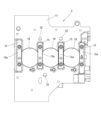
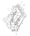
- FIG. 1 is a perspective view of a composite cylinder block of one embodiment;
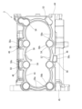
- FIG. The top view of a compound-type cylinder block.
- FIG. 8 is an enlarged view of a portion of FIG. 7;
- FIG. 3 is a perspective view of a cross section taken along line AA of FIG. 2;
- a composite cylinder block 1 is composed of two members, a main block 2 made of metal and an outer member 3 made of synthetic resin.
- 1 to 3 and 11 show the composite cylinder block 1 in a state in which the main block 2 and the outer member 3 are integrated, FIGS. 4 and 5 show the main block 2 alone, and FIG. 10 to 10 show the outer member 3 alone.
- the main block 2 and the outer member 3 are individually manufactured and welded together using a heat welding technique, which will be described later.
- the illustrated example is a cylinder block 1 for an in-line three-cylinder engine.
- 2 cylinders and #3 cylinders The direction parallel to the line on which the centers of these three cylinders line up is the "cylinder row direction,” the direction parallel to the center axis of each cylinder is the “cylinder axial direction,” and the direction perpendicular to the cylinder row direction is the "width direction.” , respectively.
- the terms “upper”, “upper”, “lower”, “lower”, etc. are used following the general direction of top dead center and bottom dead center. It should be noted that the present invention is not limited to an in-line three-cylinder engine.
- "front” of the cylinder block 1 means the #1 cylinder side in the cylinder row direction
- "rear” means the #3 cylinder side.
- the metal main block 2 integrates the parts that support the load or reaction force associated with the combustion and explosion of the internal combustion engine, and each part is integrally cast using an appropriate metal material. In one preferred embodiment, it is integrally cast by die casting using an aluminum alloy.
- the main block 2 includes a lower deck 11 having a plate shape along a plane perpendicular to the axial direction of the cylinder, a pedestal 12 rising upward from the upper surface of the lower deck 11, and the pedestal.
- Three cylindrical cylinder walls 13 further extending upward from the portion 12, a total of eight columnar portions 14 similarly rising upward from the pedestal portion 12, and four main bearing portions 15 provided on the lower surface of the lower deck 11. , is equipped with Each cylinder wall 13 defines a cylinder bore 16 , and these cylinder bores 16 extend through the base portion 12 to the lower surface of the lower deck 11 .
- the lower deck 11 spreads so as to be substantially symmetrical in the width direction with respect to the row of cylinders. (See FIG. 3).
- the plate-shaped lower deck 11 has an appropriate thickness so as to have necessary rigidity.
- the cylinder bore 16 terminates at the lower surface of the lower deck 11 . That is, the cylinder wall 13 does not protrude below the lower deck 11 .
- a crankcase constituent member for example, an oil pan (not shown) is attached to the lower surface of the lower deck 11 .
- the main bearings 15 are provided at a total of four locations, front and rear ends in the cylinder row direction and positions between cylinders, in order to rotatably support a crankshaft (not shown).
- Each of the main bearing portions 15 is formed in the shape of a relatively thick rectangular plate projecting downward from the lower surface of the lower deck 11, and has a semicircular bearing recess 15a in the center of the lower surface. ing.
- a bearing cap (not shown) is finally attached to these main bearing portions 15, and a journal portion of the crankshaft is rotatably supported via a bearing metal (not shown).
- the lower surface of the lower deck 11, except for the main bearing portion 15, forms a flat surface along one plane perpendicular to the axial direction of the cylinder.
- the cylinder wall 13 has a cylindrical shape with a substantially constant thickness (radial dimension). Further, in the illustrated example, three cylindrical cylinder walls 13 are connected to each other at a portion between cylinders to form a so-called Siamese structure. That is, the bore pitch is shorter than the outer diameter of the cylinder wall 13 .
- the inner peripheral surface of the cylinder bore 16 is provided with a cast-iron cylinder liner (not shown) or thermally sprayed with a wear-resistant metal.
- the pedestal portion 12 has a side surface 21 rising substantially perpendicularly from the upper surface of the lower deck 11 and a top surface 22 parallel to the upper and lower surfaces of the lower deck 11 .
- Each of the columnar portions 14 rises upward from the top surface 22 of the pedestal portion 12 substantially at right angles (in other words, along the axial direction of the cylinder).
- the columnar portions 14 are provided at a total of eight locations, ie, both front and rear ends in the cylinder row direction and positions between the cylinders so that the three cylinder walls 13 surround the row of cylinders.
- the first columnar portion 14A, the second columnar portion 14B, the third columnar portion 14C, the fourth columnar portion 14C, and the third columnar portion 14C are used in order from the #1 cylinder side. 14D, a fifth columnar portion 14E, a sixth columnar portion 14F, a seventh columnar portion 14G, and an eighth columnar portion 14H.
- Each column 14 is independent and separated from the cylinder wall 13 as well.
- These columnar portions 14 function as bolt boss portions to which cylinder head bolts (not shown) for fixing a cylinder head (not shown) arranged on the cylinder block 1 are screwed.
- a bolt hole 24 into which a cylinder head bolt is screwed is formed.
- the diameters of the third columnar portion 14C to the eighth columnar portion 14H are set equal to each other.
- the surface of each part along the cylinder axial direction is provided with a so-called draft angle as necessary.
- the third columnar portion 14C to the eighth columnar portion 14H have a tapered shape with a slightly smaller diameter at the upper end.
- the first columnar portion 14A has a shape as if two parallel cylinders were joined at a part of the outer peripheral surface. In other words, in a plan view such as FIG. 5 and a cross-sectional view perpendicular to the cylinder axial direction, it has a figure "8" shape. Specifically, a main columnar portion 14Aa having a diameter similar to that of the third columnar portion 14C to the eighth columnar portion 14H and a subcolumnar portion 14Ab having a smaller diameter than the main columnar portion 14Ab are integrated.
- the main cylindrical portion 14Aa functions as a bolt boss portion for a cylinder head bolt, similarly to the third columnar portion 14C to the eighth columnar portion 14H, and has a bolt hole 24 at the center of its upper end.
- the main columnar portion 14Aa is provided at a position symmetrical to the fourth columnar portion 14D with respect to the cylinder center of the #1 cylinder, that is, at a position where a total of eight cylinder head bolts are evenly arranged.
- the secondary columnar portion 14Ab is positioned diagonally outside the main columnar portion 14Aa, that is, on the side opposite to the cylinder wall 13 of the #1 cylinder.
- An oil passage 25 is formed in the center of the secondary cylindrical portion 14Ab along the axial direction of the cylinder for supplying oil pressurized by an oil pump (not shown) to the cylinder head.
- the sub-cylindrical portion 14Ab corresponds to a pipe forming the oil passage 25 having a circular cross section.
- the first columnar portion 14A is formed by connecting the main columnar portion 14Aa, which is the bolt boss portion, and the sub columnar portion 14Ab, which is the pipe of the oil passage 25, at a part of the peripheral surface.
- a pair of recessed grooves 14Ac remain on the surface.
- the second columnar portion 14B is similar to the first columnar portion 14A, and has a shape as if two parallel cylinders were joined at a part of the outer peripheral surface. In other words, in a plan view such as FIG. 5 and a cross-sectional view perpendicular to the cylinder axial direction, it has a figure "8" shape. Specifically, a main columnar portion 14Ba having a diameter smaller than that of the third columnar portion 14C to the eighth columnar portion 14H and a secondary columnar portion 14Bb having a slightly smaller diameter than the main columnar portion 14Bb are integrated.
- the main cylindrical portion 14Ba functions as a bolt boss portion for a cylinder head bolt, similarly to the third columnar portion 14C to the eighth columnar portion 14H, and has a bolt hole 24 at the center of its upper end.
- the main columnar portion 14Ba is provided at a position symmetrical to the third columnar portion 14C across the cylinder center of the #1 cylinder, that is, at a position where a total of eight cylinder head bolts are evenly arranged.
- the secondary columnar portion 14Bb is located on the front side and the inner side in the width direction of the main columnar portion 14Ba, that is, at a position next to the main columnar portion 14Ba on an arc centered on the cylinder center of the #1 cylinder.
- this secondary columnar portion 14Bb corresponds to a pipe that forms the oil passage 26 having a circular cross section.
- the second columnar portion 14B is formed by connecting the main columnar portion 14Ba as the bolt boss portion and the sub columnar portion 14Bb as the pipe of the oil passage 26 at a part of the peripheral surface.
- a pair of recessed grooves 14Bc remain on the surface.
- the second columnar portion 14B is configured so that the other columnar portions 14 (the first columnar portion 14A, the third columnar portion 14C to the eighth columnar portion 14H) are not continuous with the side surface 21 of the base portion 12. While protruding from the top surface 22 of the pedestal portion 12 , the lower portion of the second columnar portion 14 ⁇ /b>B is configured to be integrated with the side surface 21 of the pedestal portion 12 . That is, the inner portion (the portion facing the cylinder wall 13) of the outer peripheral surface of the second columnar portion 14B having an "8" cross-sectional shape rises from the top surface 22 of the base portion 12. , the outer portion (the portion opposite to the cylinder wall 13 ) extends downward from the top surface 22 and continues to the lower deck 11 .
- the lower end of the oil passage 25 passing through the first columnar portion 14A and the lower end portion of the oil passage 26 passing through the second columnar portion 14B form a sub oil gallery extending in the width direction of the main block 2 formed near the front end of the lower deck 11. (not shown).
- the sub-oil gallery extending in the width direction communicates with a main oil gallery 27 (see FIGS. 11 and 4) formed on the lower side of the row of cylinder walls 13 and extending in the direction of the row of cylinders.
- the main oil gallery 27 is supplied with pressurized high-pressure oil (lubricating oil) from an oil pump (not shown). A part of this high-pressure oil is supplied to the cylinder head side through two oil passages 25 and 26 . Further, as shown in FIG. 11, part of the high-pressure oil is supplied to the bearing recessed portion 15a through the oil passage 28 passing through the main bearing portion 15. As shown in FIG.
- the pedestal portion 12 is formed so as to protrude outward with a substantially constant width from the outer contours of the three cylinder walls 13 arranged in series, and the outer contours of the columnar portions 14 excluding the second columnar portion 14B. It is formed so as to protrude outward with a substantially constant width. That is, the shape of the side surface 21 of the base portion 12 is determined so as to follow the outer contours of the cylinder wall 13 and the columnar portion 14 and surround the outer sides thereof. Basically, the side surface 21 is a combination of a cylindrical surface concentric with the cylinder wall 13 and a cylindrical surface concentric with the columnar portion 14 .
- the top surface 22 has a substantially constant width (see symbol D1 in FIG. 5) around the cylinder wall 13 except for the portion adjacent to the columnar portion 14, and the columnar portion A top surface 22 exists around 14 with a relatively narrow, substantially constant width (see symbol D2 in FIG. 5).
- the first columnar portion 14A there is a top surface 22 having the same width as the periphery of the other columnar portions 14 along the "8" cross-sectional shape of the first columnar portion 14A.
- the width (D1 ) exists between it and the cylinder wall 13.
- the top surface 22 does not exist outside the second columnar portion 14B.
- the pedestal portion 12 has three oil drop hole forming portions 31 each having a square shape in a plan view.
- the first oil drop hole formation portion 31A is located outside the third columnar portion 14C between the #1 cylinder and the #2 cylinder, and the second oil drop hole formation portion 31B is located between the #2 cylinder and the #3 cylinder. It is positioned outside the fifth columnar portion 14E between the cylinders.
- the third oil drop hole formation portion 31C is located on the opposite side of the cylinder row from the two oil drop hole formation portions 31A and 31B, and is located between the fourth columnar portion 14D and the sixth columnar portion 14F, that is, #2. on the side of the cylinder.
- an oil drop hole lower half portion 32 extending in the axial direction of the cylinder is formed.
- this oil drop hole lower half portion 32 constitutes a part of the oil drop hole for returning the oil used in the cylinder head side into the crankcase by its own weight.
- the lower half of the oil drop hole 32 has a substantially rectangular cross-sectional shape elongated in the direction of the row of cylinders. As shown in FIG. 3, it is narrowed to a circular hole.
- the oil drop hole forming portion 31 is a part of the pedestal portion 12 and has the same height as the periphery of the cylinder wall 13, and the top of the pedestal portion 12 forming the same plane.
- a portion of surface 22 surrounds lower oil pit half 32 .
- the top surface 22 of the pedestal 12 as a whole, including the portion surrounding the cylinder wall 13, the portion surrounding the columnar portion 14, and the portion surrounding the oil drop hole lower half portion 32, is perpendicular to the cylinder axial direction. along one plane that As will be described later, the top surface 22 is a surface to be joined with the outer member 3 made of synthetic resin. .
- the synthetic resin outer member 3 is not a member that bears the load or reaction force associated with combustion and explosion of the internal combustion engine, but mainly constitutes a water jacket through which cooling water flows between the main block 2 and the outer member 3. , and constitutes an upper deck portion that serves as a joint surface with the cylinder head, and each portion is integrally constructed using an appropriate synthetic resin material.
- it is integrally injection molded using a fiber reinforced resin in which a thermoplastic resin such as a polyamide resin is blended with glass fibers.
- the outer member 3 has a substantially rectangular frame shape or tubular shape as a whole.
- the main parts of the outer member 3 are an upper deck portion 41 that serves as a joint surface or a boundary surface with the cylinder head, and a water jacket that surrounds the columnar portions 14 of the main block 2 other than the cylinder wall 13 and the second columnar portion 14B.
- the outer member 3 is combined with the main block 2 so as to cover the main block 2 while housing the cylinder wall 13 of the main block 2 on the inner peripheral side of the water jacket forming wall 42 .
- the upper deck portion 41 is continuous at the upper end of the outer member 3 in a substantially rectangular frame shape, and its upper surface forms a flat surface along one plane orthogonal to the axial direction of the cylinder.
- the upper deck portion 41 includes straight left and right side edges 41a and 41b, a front edge 41c, and a rear edge 41d.
- the side edge portions 41a and 41b are connected to the upper portion of the water jacket forming wall 42 positioned inside via several ribs 41e extending in the width direction.
- the upper end surface of the water jacket-constituting wall 42 constitutes a part of the upper deck portion 41 and extends along one plane together with the side edges 41a and 41b, the front edge 41c and the rear edge 41d.
- a cylinder head (not shown) is mounted on the upper deck portion 41 via a cylinder head gasket (not shown).
- a cylinder head gasket for example, a composite gasket is used in which the portion of the top surface of the cylinder wall 13 that contacts the metal main block 2 is a metal seal, and the portion that contacts the synthetic resin upper deck portion 41 is a rubber seal.
- the water jacket-constituting wall 42 has a shape that generally follows the outer contours of the cylinder wall 13 and the columnar portion 14 (excluding the second columnar portion 14B) of the main block 2 in a plan view, and substantially extends along the cylinder axis. It has walls parallel to the direction. More specifically, the water-jacket-constituting wall 42 has a total of eight cylinder-facing surfaces 51 , which are relatively gently curved and face the outer peripheral surface of the cylinder wall 13 without overlapping the columnar portion 14 . and a total of seven columnar portion facing surfaces 52 surrounding the columnar portions 14 other than the second columnar portion 14B. As shown in FIG.
- the seven columnar portion facing surfaces 52, the first columnar portion facing surface 52A, the third columnar portion facing surface 52C, . are individually distinguished.
- the columnar portion facing surface 52 is located between two adjacent cylinder facing surfaces 51 and has a concave shape as a concave groove surface with a relatively small radius of curvature.
- the cylinder facing surface 51 is arranged so that when combined with the main block 2, as shown in FIG. position is set.
- the columnar portion facing surface 52 forms an arcuate surface having a diameter slightly larger than the diameter of each columnar portion 14 so as to create a relatively small gap with the outer peripheral surface of each columnar portion 14.
- the third to sixth columnar portion facing surfaces 52C to 52F corresponding to the third to sixth columnar portions 14C to 14F respectively form cylindrical surfaces having substantially semicircular cross sections.
- the seventh columnar portion facing surface 52G and the eighth columnar portion facing surface 52H corresponding to the seventh columnar portion 14G and the eighth columnar portion 14H are located at positions corresponding to the corner portions of the ends of the continuous water jacket. It has a cylindrical surface with a cross section of about 3/4 circle, which is larger than a circle. That is, the seventh columnar portion 14G and the eighth columnar portion 14H are surrounded by the seventh columnar portion facing surface 52G and the eighth columnar portion facing surface 52H at about 3/4 of the circumference.
- the first columnar portion facing surface 52A corresponding to the first columnar portion 14A has a cross-sectional shape of "8" corresponding to the first columnar portion 14A so that a slight gap remains on the entire circumference. It has a cross-sectional shape along the outer shape of a letter. As a result, as shown in FIG. 1, the first columnar portion 14A is fitted into the first columnar portion facing surface 52A with a slight gap left on the entire circumference.
- the water jacket forming wall 42 is not provided with a corresponding concave groove portion (columnar portion facing surface).
- a second columnar portion insertion hole is provided outside the water jacket forming wall 42 (specifically, the first cylinder facing surface 51A to the eighth cylinder facing surface 51H) so as to be independent from the water jacket. 53 is formed in a tubular shape extending in the axial direction of the cylinder (see FIGS. 6 and 10).
- the second columnar portion insertion hole 53 has a cross section along the outer shape of the character "8" so that a slight gap remains on the entire circumference corresponding to the second columnar portion 14B having the shape of "8" in cross section. have a shape.
- the upper end of the second columnar insertion hole 53 having a cross-sectional shape along the outer shape of the figure "8" opens to the upper surface of the upper deck portion 41 and extends downward therefrom.
- the second columnar portion 14B is fitted into the second columnar portion insertion hole 53 with a slight gap left on the entire circumference.
- the joint flange portion 43 projecting inwardly from the lower end of the water jacket-constituting wall 42 is formed along one plane perpendicular to the axial direction of the cylinder together with the lower end surface of the water jacket-constituting wall 42, and is joined to the outer member side. It constitutes the surface 57 .
- the outer member side joint surface 57 basically has a shape corresponding to the area of the top surface 22 of the pedestal portion 12 of the main block 2 . That is, the joint flange portion 43 protrudes like an eave along the contour of the periphery of the three cylinder walls 13 connected in series on the top surface 22 of the pedestal portion 12, and seven columnar portions excluding the second columnar portion 14B are provided.
- Seven openings 54 corresponding to the portions 14 are provided, and an outer member-side joint surface 57 is continuously formed on the lower surfaces of these openings 54 .
- the six openings 54 for the third columnar portion 14C to the eighth columnar portion 14H are circular, and the opening portion 54 for the first columnar portion 14A is approximately "8" in size similar to the first columnar portion facing surface 52A. form a glyph.
- the outer opening edge of each opening 54 is continuous with the corresponding columnar portion facing surface 52 in the cylinder axial direction without a step.
- a welding rib 56 projecting downward in the form of a bead having a constant width is formed from the joint surface 57 on the outer member side.
- the welding ribs 56 are composed of main welding ribs 56a that are continuous along the entire circumference so as to pass through the outer sides of the three cylinder walls 13 and the seven columnar portions 14 in the same manner as the outline of the water jacket-constituting wall 42, and seven openings.
- Arc-shaped welding ribs 56b for columnar portions are provided along the inner portion of 54 (the portion entering between the cylinders), and the welding ribs 56b for columnar portions are continuous with the main welding ribs 56a.
- the oil drop hole forming portions 46 of the outer member 3 are provided at three locations on the outer member 3 so as to respectively correspond to the oil drop hole forming portions 31 on the main block 2 side.
- Each oil drop hole forming portion 46 protrudes downward from the upper deck portion 41 in a tubular path shape, and an oil drop hole upper half portion 58 extending in the cylinder axial direction is formed on the inner peripheral side.
- the oil drop hole upper half portion 58 is continuous with the oil drop hole lower half portion 32 on the main block 2 side to form an oil drop hole extending from the cylinder head to the crankcase.
- the upper end of the oil dropping hole upper half portion 58 is open between the side edge portions 41 a and 41 b of the upper deck portion 41 and the water jacket constituting wall 42 . As shown in FIGS.
- the lower end of the oil drop hole upper half portion 58 opens in an elongated shape along the direction of the row of cylinders on the same plane as the joint flange portion 43 and the lower surface of the water jacket-constituting wall 42 . ing. That is, the lower end surface of the oil drop hole forming portion 46 constitutes a part of the outer member side joint surface 57 , and the lower end of the oil drop hole upper half portion 58 opens to this outer member side joint surface 57 .
- a weld rib 56 similar to that described above (an oil drop hole weld rib 56 c ) is formed on the outer member side joint surface 57 so as to surround the oil drop hole upper half portion 58 .
- the upper end of the front flange portion 44 is continuous with the front edge portion 41c of the upper deck portion 41 and forms a relatively rigid flange surface 44a (see FIG. 6).
- the rear flange portion 45 has an upper end portion which is continuous with the rear edge portion 41d of the upper deck portion 41 and forms a relatively rigid flange surface 45a (see FIG. 7).
- the flange surfaces 44a, 45a are along a plane orthogonal to the row of cylinders direction.
- the lower side wall portion 47 extends downward along the cylinder axial direction from a position on the outer peripheral side of the outer member side joint surface 57 so as to cover the periphery of the pedestal portion 12 on the main block 2 side.
- the lower end of the lower side wall portion 47 is configured to reach near the upper surface of the upper deck portion 41 when combined with the main block 2 .
- the lower side wall portion 47 is notched at the location of the oil drop hole forming portion 46 in order to avoid interference with the oil drop hole forming portion 31 on the main block 2 side.
- a cooling water inlet 59 (see FIG. 6) extending from the outer surface of the outer member 3 to the water jacket is provided on the eighth cylinder facing surface 51H on the side of the #1 cylinder.
- the main block 2 made of metal and the outer member 3 made of synthetic resin are individually manufactured and then joined using a heat welding technique (a kind of hot plate welding).
- the joint is made between the top surface 22 of the base portion 12 and the outer member side joint surface 57 .
- a heater for heating is arranged on the lower surface of the lower deck 11 of the metal main block 2, and the pedestal portion 12 is heated from below while the main block 2 and the outer member 3 are separated from each other.
- the heater has, for example, a plate-like structure having four rectangular openings through which the main bearings 15 penetrate, and is provided in a range that covers at least the projection plane of the pedestal 12, and is substantially on the lower surface of the lower deck 11. placed in close proximity.
- the temperature of the vicinity of the top surface 22 of the pedestal portion 12, which is the joint surface on the main block 2 side, is raised to an appropriate temperature (for example, 200 to 300° C.), the outer member side joint surface 57 is brought into close contact with the top surface 22 of the pedestal portion 12 , and the outer member 3 is pressed toward the main block 2 .
- the welding ribs 56 are melted and the main block 2 and the outer member 3 are integrally joined. Therefore, the welding rib 56 becomes a substantial sealing line between the two.
- the top surface 22 of the pedestal portion 12, which serves as the bonding surface may be previously treated with an appropriate primer.
- a water jacket that serves as a flow path for cooling water is formed between the cylinder wall 13 of the main block 2 and the water jacket forming wall 42 of the outer member 3 in the integrally joined state.
- This water jacket is sealed by the joint between the top surface 22 of the pedestal portion 12 provided so as to surround the cylinder wall 13 and the outer member side joint surface 57 .
- the water jacket is sealed at the welding rib 56 which becomes the sealing line shown in FIG.
- the upper end surface of the cylinder wall 13 of the main block 2 and the upper surface of the upper deck portion 41 of the outer member 3 are aligned substantially on the same plane.
- the seal between the upper deck portion 41 of the outer member 3 and the cylinder head is a rubber seal
- the upper surface of the upper deck portion 41 may be slightly lower than the upper end surface of the cylinder wall 13 of the main block 2 . .
- the seven columnar portions 14 other than the second columnar portion 14B are all inside the water jacket, and the outer peripheral surface of the columnar portion 14 is surrounded by cooling water.
- the seal line made up of the welding ribs 56 passes through the outside of the seven columnar portions 14, that is, the outside of the opening 54 (on the side of the water jacket forming wall 42), and seals the water jacket including the seven columnar portions 14. ing. Therefore, for example, as shown in FIG. 11, a relatively narrow water jacket exists between the outer peripheral surface of the columnar portion 14 and the water jacket forming wall 42 (the columnar portion facing surface 52).
- the second columnar portion 14B is accommodated in the second columnar portion insertion hole 53 of the outer member 3 and is isolated from the water jacket.
- the second columnar portion 14B is surrounded by the wall surrounding the second columnar portion insertion hole 53 made of synthetic resin and does not come into contact with the cooling water.
- a cylinder head (not shown) is arranged on the upper surface of the upper deck portion 41 and fixed via cylinder head bolts.
- the cylinder head bolts are screwed into the bolt holes 24 of the columnar portion 14 respectively.
- the columnar portions 14 that serve as bolt boss portions are all continuous in a straight line along the cylinder axial direction up to the pedestal portion 12 , and linearly transmit the load along the bolt axial direction to the pedestal portion 12 .
- the pedestal portion 12 is thick and rigid, and reliably supports the load acting from the cylinder head.
- the main bearing portion 15 is integrated with the rigid base portion 12 and can reliably support the crankshaft.
- the oil drop hole forming portion 31 of the main block 2 and the oil drop hole forming portion 46 of the outer member 3 are joined to face each other as shown in FIGS.
- the welding ribs 56 (56c) provided on the outer member 3 side are melted and softened and joined to the joint surface (top surface 22) on the main block 2 side.
- the oil drop hole lower half portion 32 and the oil drop hole upper half portion 58 are continuous as a single passage, forming an oil drop hole.
- the upper end of the oil drop hole is further connected to the oil drop hole on the cylinder head side.
- the composite cylinder block 1 of the above embodiment is configured so that the metal main block 2 that receives the load and the reaction force has a minimum volume, and many parts such as the wall 42 constituting the water jacket are constructed. Since the portion is made of synthetic resin as the outer member 3, a significant weight reduction can be realized.
- the cylinder block 1 of the above embodiment has a metal main block 2 and a resin outer member 3 welded to the main block 2 .
- the main block 2 has a cylinder wall 13 forming a cylinder bore 16 and a columnar portion 14 formed at a position separated from the cylinder wall 13 .
- the outer member 3 has a water jacket forming wall 42 forming a water jacket between itself and the cylinder wall 13 , and a second columnar portion insertion hole 53 .
- the second columnar portion 14B is provided in the second columnar portion insertion hole 53 in the outer member 3 in a state of being isolated from the water jacket, and between the second columnar portion insertion hole 53 in the outer member 3 and the entire circumference. It is accommodated so as to have a predetermined gap over the entire length and reaches the cylinder head.
- the thermally expanded second columnar portion 14B does not interfere with the second columnar portion insertion hole 53 in the outer member 3. Therefore, the outer member 3 can be easily arranged at the desired position of the main block 2 .
- the gap between the inner wall surface of the second columnar portion insertion hole 53 and the outer peripheral surface of the second columnar portion 14B becomes an air layer (heat insulating layer). While the engine is warming up (while the internal combustion engine is warming up), the oil in the second columnar portion 14B and the oil passage 26 is less likely to be cooled by the cooling water, and overall warm-up performance can be improved.
- the oil passage 25 is formed within the metal first columnar portion 14A.
- the oil passage 26 is formed in the metal second columnar portion 14B. Therefore, the cylinder block 1 can ensure pressure resistance.
- the second columnar portion 14B includes a main columnar portion 14Ba as a main columnar portion into which cylinder head bolts for fixing the cylinder head are screwed, and an oil passage 26 for supplying oil pressurized by an oil pump to the cylinder head. is integrated with the sub-cylindrical portion 14Bb as a sub-columnar portion provided inside.
- the cylinder block 1 can suppress deformation during casting.
- the second columnar portion 14B has a pair of recessed groove portions 14Bc on the outer peripheral surface between the main columnar portion 14Ba and the sub columnar portion 14Bb. Since the second columnar portion 14B has the pair of recessed grooves 14Bc, the second columnar portion 14B is hollowed out compared to the case where the cross section has an oval shape without the pair of recessed grooves 14Bc.
- the weight of the cylinder block 1 can be reduced by providing the second columnar portion 14B with the pair of concave groove portions 14Bc.
- the present invention is not limited to the above embodiment, and various modifications are possible.
- the second columnar portion 14B of the embodiment described above has at least the bolt holes 24, the second columnar portion 14B may not have the bolt holes 24.
- the second columnar portion 14B may have only an oil passage for supplying the oil pressurized by the oil pump to the cylinder head.
- the second columnar portion 14B may be composed of only the secondary columnar portion 14Ab described above.
- the second columnar portion 14B of the columnar portions 14 is accommodated in the outer member 3 in a state isolated from the water jacket. It may be configured to be housed in the member 3 in a state isolated from the water jacket. In this case, all the columnar portions 14 are housed in the outer member 3 in a state isolated from the water jacket and with a predetermined gap from the outer member 3 along the entire circumference.
- the cylinder block should be configured so that the
Landscapes
- Engineering & Computer Science (AREA)
- Chemical & Material Sciences (AREA)
- Combustion & Propulsion (AREA)
- Mechanical Engineering (AREA)
- General Engineering & Computer Science (AREA)
- Cylinder Crankcases Of Internal Combustion Engines (AREA)
Abstract
A cylinder block (1) comprises a metal main block (2), and a resin outer member (3) which is welded to the main block (2). The main block (2) has a cylinder wall (13) forming a cylinder bore (16), and a second columnar portion (14B) spaced apart from the cylinder wall (13). The outer member (3) has a second columnar portion insertion hole (53), and forms a water jacket between the cylinder wall (13) and the outer member (3). The second columnar portion (14B) is accommodated in the second columnar portion insertion hole (53) in a state of being isolated from the water jacket, with a predetermined gap between the second columnar portion and the second columnar portion insertion hole (53), and reaches a cylinder head.
Description
本発明、金属製部材と合成樹脂製部材とを組み合わせて構成された内燃機関の複合型シリンダブロックに関する。
The present invention relates to a composite cylinder block for an internal combustion engine constructed by combining metal members and synthetic resin members.
例えば、特許文献1には、金属製のシリンダライナの外周面に樹脂ブロックを取り付けたエンジンブロックが開示されている。
For example, Patent Document 1 discloses an engine block in which a resin block is attached to the outer peripheral surface of a metal cylinder liner.
特許文献1のエンジンブロックは、シリンダライナ及び樹脂ブロックに加え、金属製のブロック部材と金属製の突起を備えている。
The engine block of Patent Document 1 includes a metal block member and a metal projection in addition to the cylinder liner and resin block.
特許文献1のブロック部材は、金属製で樹脂ブロックを支持するためベースとして機能する。
The block member of Patent Document 1 is made of metal and functions as a base to support the resin block.
特許文献1の突起は、シリンダヘッドを固定するためのボルトが挿入される開口を有するものであって、ブロック部材からシリンダヘッドに向けて突出している。
The protrusion of Patent Document 1 has an opening into which a bolt for fixing the cylinder head is inserted, and protrudes from the block member toward the cylinder head.
この特許文献1においては、シリンダライナからの熱による樹脂ブロックの損傷を樹脂ブロック内に形成されたウォータジャケットによって低減している。
In Patent Document 1, damage to the resin block due to heat from the cylinder liner is reduced by a water jacket formed inside the resin block.
しかしながら、特許文献1のエンジンブロックは、ウォータジャケットの外側に位置する突起の暖機、ひいてはエンジンブロックの暖機に関して何ら開示されていない。
However, the engine block of Patent Document 1 does not disclose anything regarding warming up of the protrusions located outside the water jacket, and thus warming up of the engine block.
すなわち、エンジンブロックを金属部品と樹脂部品とで構成するにあたっては、金属部品の暖機を考慮する上で更なる改善の余地がある。
In other words, there is room for further improvement in considering the warm-up of the metal parts when configuring the engine block with metal parts and resin parts.
本発明の複合型シリンダブロックは、金属製のメインブロックと、上記メインブロックに溶着された樹脂製のアウタ部材と、を有し、上記メインブロックは、シリンダボアを構成するシリンダ壁と、上記シリンダ壁から離間した位置に形成された柱状部と、を有し、上記アウタ部材は、上記シリンダ壁との間にウォータジャケットを構成し、上記柱状部は、上記アウタ部材内に上記ウォータジャケットから隔絶した状態で、かつ当該アウタ部材との間に所定の隙間を有するように収容されるとともに、シリンダヘッドまで達している。
A composite cylinder block according to the present invention includes a metal main block and a resin outer member welded to the main block, the main block including a cylinder wall forming a cylinder bore and the cylinder wall. a column formed at a position spaced from the outer member forming a water jacket between the outer member and the cylinder wall, the column being isolated from the water jacket within the outer member; It is housed in such a state that it has a predetermined gap with respect to the outer member, and reaches the cylinder head.
本発明の複合型シリンダブロックは、メインブロックの柱状部とアウタ部材との間の隙間が空気層(断熱層)となるので、エンジン暖機中(内燃機関暖機中)に冷却水により柱状部が冷却されにくくなり、暖機性を向上させることができる。
In the composite cylinder block of the present invention, since the gap between the columnar portion of the main block and the outer member serves as an air layer (insulating layer), the columnar portion is cooled by cooling water during engine warm-up (during internal combustion engine warm-up). is less likely to be cooled, and warm-up performance can be improved.
以下、この発明の一実施例を図面に基づいて詳細に説明する。
An embodiment of the present invention will be described in detail below with reference to the drawings.
初めに、一実施例の複合型シリンダブロック1の全体的な構成を説明する。複合型シリンダブロック1は、金属製のメインブロック2と、合成樹脂製のアウタ部材3と、の2つの部材から構成されている。図1~図3および図11は、メインブロック2とアウタ部材3とを一体化した状態での複合型シリンダブロック1を示し、図4、図5は、メインブロック2を単体で示し、図6~図10は、アウタ部材3を単体で示している。メインブロック2およびアウタ部材3は、それぞれ個別に製造され、後述する加熱溶着技術を用いて一体に溶着されている。
First, the overall configuration of the composite cylinder block 1 of one embodiment will be described. A composite cylinder block 1 is composed of two members, a main block 2 made of metal and an outer member 3 made of synthetic resin. 1 to 3 and 11 show the composite cylinder block 1 in a state in which the main block 2 and the outer member 3 are integrated, FIGS. 4 and 5 show the main block 2 alone, and FIG. 10 to 10 show the outer member 3 alone. The main block 2 and the outer member 3 are individually manufactured and welded together using a heat welding technique, which will be described later.
図示例は、直列3気筒機関用のシリンダブロック1であり、説明の便宜のために、図1に「♯1」等と付したように、図1の右手前側から順に、♯1気筒、♯2気筒、♯3気筒、と呼ぶこととする。そして、これら3つの気筒の中心が並ぶ直線と平行な方向を「気筒列方向」、各気筒の中心軸と平行な方向を「シリンダ軸方向」、気筒列方向と直交する方向を「幅方向」、とそれぞれ呼ぶこととする。また、一般的な上死点および下死点の方向に倣って、「上」、「上方」、「下」、「下方」等の語を用いる。なお、本発明は、直列3気筒機関に限定されるものではない。さらに、シリンダブロック1の「前」は気筒列方向について♯1気筒側を意味し、「後」は♯3気筒側を意味する。
The illustrated example is a cylinder block 1 for an in-line three-cylinder engine. For convenience of explanation, as indicated by "#1" in FIG. These are called 2 cylinders and #3 cylinders. The direction parallel to the line on which the centers of these three cylinders line up is the "cylinder row direction," the direction parallel to the center axis of each cylinder is the "cylinder axial direction," and the direction perpendicular to the cylinder row direction is the "width direction." , respectively. Also, the terms "upper", "upper", "lower", "lower", etc. are used following the general direction of top dead center and bottom dead center. It should be noted that the present invention is not limited to an in-line three-cylinder engine. Furthermore, "front" of the cylinder block 1 means the #1 cylinder side in the cylinder row direction, and "rear" means the #3 cylinder side.
金属製のメインブロック2は、内燃機関の燃焼・爆発に伴う荷重ないし反力を支承する部分を一体に集約したものであり、適宜な金属材料を用いて各部一体に鋳造されている。好ましい一実施例では、アルミニウム合金を用いてダイキャスト製法により一体に鋳造されている。図4、図5に示すように、メインブロック2は、シリンダ軸方向と直交する平面に沿った板状をなすロアデッキ11と、このロアデッキ11の上面から上方へ立ち上がった台座部12と、この台座部12からさらに上方へ延びた3つの円筒形のシリンダ壁13と、同じく台座部12から上方へ立ち上がった計8つの柱状部14と、ロアデッキ11の下面に設けられた4つの主軸受部15と、を備えている。各々のシリンダ壁13によってシリンダボア16が構成されており、これらのシリンダボア16は、台座部12を貫通してロアデッキ11の下面まで延びている。
The metal main block 2 integrates the parts that support the load or reaction force associated with the combustion and explosion of the internal combustion engine, and each part is integrally cast using an appropriate metal material. In one preferred embodiment, it is integrally cast by die casting using an aluminum alloy. As shown in FIGS. 4 and 5, the main block 2 includes a lower deck 11 having a plate shape along a plane perpendicular to the axial direction of the cylinder, a pedestal 12 rising upward from the upper surface of the lower deck 11, and the pedestal. Three cylindrical cylinder walls 13 further extending upward from the portion 12, a total of eight columnar portions 14 similarly rising upward from the pedestal portion 12, and four main bearing portions 15 provided on the lower surface of the lower deck 11. , is equipped with Each cylinder wall 13 defines a cylinder bore 16 , and these cylinder bores 16 extend through the base portion 12 to the lower surface of the lower deck 11 .
ロアデッキ11は、気筒列を中心として幅方向に略対称をなすよう拡がっており、♯3気筒側の部分では幅方向寸法が相対的に大きく、♯1気筒側の部分では幅方向寸法が相対的に小さく構成されている(図3参照)。板状のロアデッキ11は、必要な剛性を有するように適当な厚さを有する。なお、シリンダボア16は、ロアデッキ11の下面で終端している。つまりシリンダ壁13はロアデッキ11よりも下方へは突出していない。最終的に内燃機関として組み立てられた状態では、ロアデッキ11の下面に図示しないクランクケース構成部材(例えばオイルパン)が取り付けられる。
The lower deck 11 spreads so as to be substantially symmetrical in the width direction with respect to the row of cylinders. (See FIG. 3). The plate-shaped lower deck 11 has an appropriate thickness so as to have necessary rigidity. Note that the cylinder bore 16 terminates at the lower surface of the lower deck 11 . That is, the cylinder wall 13 does not protrude below the lower deck 11 . When the internal combustion engine is finally assembled, a crankcase constituent member (for example, an oil pan) (not shown) is attached to the lower surface of the lower deck 11 .
主軸受部15は、図示しないクランクシャフトを回転自在に支持するために、気筒列方向の前後両端と気筒間位置との計4カ所に設けられている。主軸受部15は、それぞれ長方形の比較的に厚肉の板状をなすようにロアデッキ11の下面から下方へ突出して形成されており、それぞれの下面中央に、半円形をなす軸受凹部15aを備えている。これらの主軸受部15には、最終的に図示しないベアリングキャップが取り付けられ、図示しないベアリングメタルを介してクランクシャフトのジャーナル部が回転自在に支持される。ロアデッキ11の下面は、主軸受部15を除き、シリンダ軸方向と直交する1つの平面に沿った平坦面をなしている。
The main bearings 15 are provided at a total of four locations, front and rear ends in the cylinder row direction and positions between cylinders, in order to rotatably support a crankshaft (not shown). Each of the main bearing portions 15 is formed in the shape of a relatively thick rectangular plate projecting downward from the lower surface of the lower deck 11, and has a semicircular bearing recess 15a in the center of the lower surface. ing. A bearing cap (not shown) is finally attached to these main bearing portions 15, and a journal portion of the crankshaft is rotatably supported via a bearing metal (not shown). The lower surface of the lower deck 11, except for the main bearing portion 15, forms a flat surface along one plane perpendicular to the axial direction of the cylinder.
シリンダ壁13は、実質的に一定の厚さ(半径方向寸法)を有する円筒形をなしている。また、図示例では、3つの円筒形のシリンダ壁13が気筒間部分で互いに連結されたいわゆるサイアミーズ構造をなしている。つまり、シリンダ壁13の外径よりもボアピッチが短くなっている。図示例ではメインブロック2がアルミニウム合金から形成されているので、シリンダボア16の内周面に、図示しない鋳鉄製のシリンダライナの挿入や耐摩耗性金属の溶射等がなされる。
The cylinder wall 13 has a cylindrical shape with a substantially constant thickness (radial dimension). Further, in the illustrated example, three cylindrical cylinder walls 13 are connected to each other at a portion between cylinders to form a so-called Siamese structure. That is, the bore pitch is shorter than the outer diameter of the cylinder wall 13 . In the illustrated example, since the main block 2 is made of an aluminum alloy, the inner peripheral surface of the cylinder bore 16 is provided with a cast-iron cylinder liner (not shown) or thermally sprayed with a wear-resistant metal.
台座部12は、ロアデッキ11の上面から実質的に直角に立ち上がる側面21と、ロアデッキ11の上面および下面と平行な頂面22と、を有する。柱状部14は、それぞれ台座部12の頂面22から上方へ実質的に直角に(換言すればシリンダ軸方向に沿って)立ち上がっている。
The pedestal portion 12 has a side surface 21 rising substantially perpendicularly from the upper surface of the lower deck 11 and a top surface 22 parallel to the upper and lower surfaces of the lower deck 11 . Each of the columnar portions 14 rises upward from the top surface 22 of the pedestal portion 12 substantially at right angles (in other words, along the axial direction of the cylinder).
柱状部14は、3つのシリンダ壁13が一連となった気筒列を囲むように、気筒列方向の前後両端と気筒間位置との計8カ所にそれぞれ設けられている。以下では、各々を区別する必要がある場合には、図4に示すように、♯1気筒側から順に、第1柱状部14A、第2柱状部14B、第3柱状部14C、第4柱状部14D、第5柱状部14E、第6柱状部14F、第7柱状部14G、第8柱状部14H、と呼び、区別の必要がない場合は柱状部14と総称する。各々の柱状部14は個々に独立しており、シリンダ壁13からも分離している。これらの柱状部14は、シリンダブロック1の上に配置される図示しないシリンダヘッドを固定するためのシリンダヘッドボルト(図示せず)がそれぞれ螺合するボルトボス部として機能するものである。
The columnar portions 14 are provided at a total of eight locations, ie, both front and rear ends in the cylinder row direction and positions between the cylinders so that the three cylinder walls 13 surround the row of cylinders. Hereinafter, when it is necessary to distinguish between them, as shown in FIG. 4, the first columnar portion 14A, the second columnar portion 14B, the third columnar portion 14C, the fourth columnar portion 14C, and the third columnar portion 14C are used in order from the #1 cylinder side. 14D, a fifth columnar portion 14E, a sixth columnar portion 14F, a seventh columnar portion 14G, and an eighth columnar portion 14H. Each column 14 is independent and separated from the cylinder wall 13 as well. These columnar portions 14 function as bolt boss portions to which cylinder head bolts (not shown) for fixing a cylinder head (not shown) arranged on the cylinder block 1 are screwed.
第1柱状部14Aおよび第2柱状部14Bを除く6つの柱状部14つまり第3柱状部14C~第8柱状部14Hは、それぞれ断面円形の単純な円柱形をなしており、上端部の中心にシリンダヘッドボルトが螺合するボルト孔24が形成されている。基本的に第3柱状部14C~第8柱状部14Hの径は、互いに等しく設定されている。ここで、図示例では、メインブロック2がダイキャスト製法により鋳造されることから、シリンダ軸方向に沿った各部の面に、必要に応じていわゆる抜き勾配が与えられており、従って、円柱形である第3柱状部14C~第8柱状部14Hは、厳密には、上端部が僅かに小径となったテーパ状をなしている。
The six columnar portions 14 excluding the first columnar portion 14A and the second columnar portion 14B, that is, the third columnar portion 14C to the eighth columnar portion 14H, each have a simple circular columnar shape with a circular cross section. A bolt hole 24 into which a cylinder head bolt is screwed is formed. Basically, the diameters of the third columnar portion 14C to the eighth columnar portion 14H are set equal to each other. Here, in the illustrated example, since the main block 2 is cast by a die casting method, the surface of each part along the cylinder axial direction is provided with a so-called draft angle as necessary. Strictly speaking, the third columnar portion 14C to the eighth columnar portion 14H have a tapered shape with a slightly smaller diameter at the upper end.
第3柱状部14C~第8柱状部14Hと異なり、第1柱状部14Aは、2本の平行な円柱を外周面の一部で接合したかのような形状をなしている。換言すれば、図5のような平面図およびシリンダ軸方向と直交する断面図において、「8」の字の形状をなしている。具体的には、第3柱状部14C~第8柱状部14Hと同様の径を有する主円柱部14Aaと、これよりも小径な副円柱部14Abと、が一体となっている。主円柱部14Aaは、第3柱状部14C~第8柱状部14Hと同様にシリンダヘッドボルトのためのボルトボス部として機能する部分であり、上端部中心にボルト孔24を有する。この主円柱部14Aaは、♯1気筒の気筒中心を挟んで第4柱状部14Dと対称となる位置、つまり計8本のシリンダヘッドボルトの配置が均等となる位置、に設けられている。副円柱部14Abは、主円柱部14Aaの斜め外側つまり♯1気筒のシリンダ壁13とは反対側となる位置にある。この副円柱部14Abの中心には、図外のオイルポンプで加圧されたオイルをシリンダヘッドへ供給するためのシリンダ軸方向に沿ったオイル通路25が形成されている。換言すれば、副円柱部14Abは、断面円形のオイル通路25を構成する管に相当する。このように、第1柱状部14Aは、ボルトボス部となる主円柱部14Aaとオイル通路25の管となる副円柱部14Abとが周面の一部で接続されたものであり、両者間の外周面には、一対の凹溝部14Acが残存する。
Unlike the third columnar portion 14C to the eighth columnar portion 14H, the first columnar portion 14A has a shape as if two parallel cylinders were joined at a part of the outer peripheral surface. In other words, in a plan view such as FIG. 5 and a cross-sectional view perpendicular to the cylinder axial direction, it has a figure "8" shape. Specifically, a main columnar portion 14Aa having a diameter similar to that of the third columnar portion 14C to the eighth columnar portion 14H and a subcolumnar portion 14Ab having a smaller diameter than the main columnar portion 14Ab are integrated. The main cylindrical portion 14Aa functions as a bolt boss portion for a cylinder head bolt, similarly to the third columnar portion 14C to the eighth columnar portion 14H, and has a bolt hole 24 at the center of its upper end. The main columnar portion 14Aa is provided at a position symmetrical to the fourth columnar portion 14D with respect to the cylinder center of the #1 cylinder, that is, at a position where a total of eight cylinder head bolts are evenly arranged. The secondary columnar portion 14Ab is positioned diagonally outside the main columnar portion 14Aa, that is, on the side opposite to the cylinder wall 13 of the #1 cylinder. An oil passage 25 is formed in the center of the secondary cylindrical portion 14Ab along the axial direction of the cylinder for supplying oil pressurized by an oil pump (not shown) to the cylinder head. In other words, the sub-cylindrical portion 14Ab corresponds to a pipe forming the oil passage 25 having a circular cross section. In this way, the first columnar portion 14A is formed by connecting the main columnar portion 14Aa, which is the bolt boss portion, and the sub columnar portion 14Ab, which is the pipe of the oil passage 25, at a part of the peripheral surface. A pair of recessed grooves 14Ac remain on the surface.
第2柱状部14Bは、第1柱状部14Aと類似しており、2本の平行な円柱を外周面の一部で接合したかのような形状をなしている。換言すれば、図5のような平面図およびシリンダ軸方向と直交する断面図において、「8」の字の形状をなしている。具体的には、第3柱状部14C~第8柱状部14Hよりも小径な主円柱部14Baと、これよりも僅かに小径な副円柱部14Bbと、が一体となっている。主円柱部14Baは、第3柱状部14C~第8柱状部14Hと同様にシリンダヘッドボルトのためのボルトボス部として機能する部分であり、上端部中心にボルト孔24を有する。この主円柱部14Baは、♯1気筒の気筒中心を挟んで第3柱状部14Cと対称となる位置、つまり計8本のシリンダヘッドボルトの配置が均等となる位置、に設けられている。副円柱部14Bbは、主円柱部14Baの前側かつ幅方向内側、つまり、♯1気筒の気筒中心を中心とする円弧上において主円柱部14Baの隣りに並ぶ位置にある。この副円柱部14Bbの中心には、第1柱状部14Aの副円柱部14Abと同様に、図外のオイルポンプで加圧されたオイルをシリンダヘッドへ供給するためのシリンダ軸方向に沿ったオイル通路26が形成されている。換言すれば、副円柱部14Bbは、断面円形のオイル通路26を構成する管に相当する。このように、第2柱状部14Bは、ボルトボス部となる主円柱部14Baとオイル通路26の管となる副円柱部14Bbとが周面の一部で接続されたものであり、両者間の外周面には、一対の凹溝部14Bcが残存する。
The second columnar portion 14B is similar to the first columnar portion 14A, and has a shape as if two parallel cylinders were joined at a part of the outer peripheral surface. In other words, in a plan view such as FIG. 5 and a cross-sectional view perpendicular to the cylinder axial direction, it has a figure "8" shape. Specifically, a main columnar portion 14Ba having a diameter smaller than that of the third columnar portion 14C to the eighth columnar portion 14H and a secondary columnar portion 14Bb having a slightly smaller diameter than the main columnar portion 14Bb are integrated. The main cylindrical portion 14Ba functions as a bolt boss portion for a cylinder head bolt, similarly to the third columnar portion 14C to the eighth columnar portion 14H, and has a bolt hole 24 at the center of its upper end. The main columnar portion 14Ba is provided at a position symmetrical to the third columnar portion 14C across the cylinder center of the #1 cylinder, that is, at a position where a total of eight cylinder head bolts are evenly arranged. The secondary columnar portion 14Bb is located on the front side and the inner side in the width direction of the main columnar portion 14Ba, that is, at a position next to the main columnar portion 14Ba on an arc centered on the cylinder center of the #1 cylinder. At the center of this secondary columnar portion 14Bb, similarly to the secondary columnar portion 14Ab of the first columnar portion 14A, there is oil along the cylinder axis direction for supplying oil pressurized by an oil pump (not shown) to the cylinder head. A passage 26 is formed. In other words, the secondary columnar portion 14Bb corresponds to a pipe that forms the oil passage 26 having a circular cross section. In this way, the second columnar portion 14B is formed by connecting the main columnar portion 14Ba as the bolt boss portion and the sub columnar portion 14Bb as the pipe of the oil passage 26 at a part of the peripheral surface. A pair of recessed grooves 14Bc remain on the surface.
また、図示例では、第2柱状部14Bは、他の柱状部14(第1柱状部14A、第3柱状部14C~第8柱状部14H)が台座部12の側面21とは連続せずに台座部12の頂面22から突出しているのに対し、当該第2柱状部14Bの下部部分が台座部12の側面21と一体化したような形に構成されている。つまり、「8」の字形の断面形状をなす第2柱状部14Bの外周面の中で、その内側部分(シリンダ壁13へ向かう部分)は台座部12の頂面22から立ち上がっているのに対し、外側部分(シリンダ壁13とは反対側となる部分)は頂面22よりも下方へ延びてロアデッキ11まで連続したような形となっている。
Further, in the illustrated example, the second columnar portion 14B is configured so that the other columnar portions 14 (the first columnar portion 14A, the third columnar portion 14C to the eighth columnar portion 14H) are not continuous with the side surface 21 of the base portion 12. While protruding from the top surface 22 of the pedestal portion 12 , the lower portion of the second columnar portion 14</b>B is configured to be integrated with the side surface 21 of the pedestal portion 12 . That is, the inner portion (the portion facing the cylinder wall 13) of the outer peripheral surface of the second columnar portion 14B having an "8" cross-sectional shape rises from the top surface 22 of the base portion 12. , the outer portion (the portion opposite to the cylinder wall 13 ) extends downward from the top surface 22 and continues to the lower deck 11 .
第1柱状部14Aを通るオイル通路25の下端部および第2柱状部14Bを通るオイル通路26の下端部は、ロアデッキ11の前端部付近に形成されたメインブロック2の幅方向に延びるサブオイルギャラリ(図示せず)にそれぞれ連通している。そして、この幅方向に沿ったサブオイルギャラリは、シリンダ壁13の列の下部側方に形成された気筒列方向に沿って延びたメインオイルギャラリ27(図11、図4参照)に連通している。メインオイルギャラリ27には図外のオイルポンプから加圧された高圧のオイル(潤滑油)が供給される。この高圧のオイルの一部は、2本のオイル通路25、26を介してシリンダヘッド側へ供給される。また、図11に示すように、高圧のオイルの一部は、主軸受部15内を通るオイル通路28を介して軸受凹部15aへと供給される。
The lower end of the oil passage 25 passing through the first columnar portion 14A and the lower end portion of the oil passage 26 passing through the second columnar portion 14B form a sub oil gallery extending in the width direction of the main block 2 formed near the front end of the lower deck 11. (not shown). The sub-oil gallery extending in the width direction communicates with a main oil gallery 27 (see FIGS. 11 and 4) formed on the lower side of the row of cylinder walls 13 and extending in the direction of the row of cylinders. there is The main oil gallery 27 is supplied with pressurized high-pressure oil (lubricating oil) from an oil pump (not shown). A part of this high-pressure oil is supplied to the cylinder head side through two oil passages 25 and 26 . Further, as shown in FIG. 11, part of the high-pressure oil is supplied to the bearing recessed portion 15a through the oil passage 28 passing through the main bearing portion 15. As shown in FIG.
台座部12は、直列に並んだ3つのシリンダ壁13の外側の輪郭から略一定の幅で外側に張り出すように形成されているとともに、第2柱状部14Bを除く柱状部14の外側の輪郭から略一定の幅で外側に張り出すように形成されている。つまり、シリンダ壁13および柱状部14の外側の輪郭に沿いつつその外側を囲むように台座部12の側面21の形状が定められている。基本的に、側面21は、シリンダ壁13と同心円をなす円筒面と、柱状部14と同心円をなす円筒面と、を組み合わせたものとなっている。
The pedestal portion 12 is formed so as to protrude outward with a substantially constant width from the outer contours of the three cylinder walls 13 arranged in series, and the outer contours of the columnar portions 14 excluding the second columnar portion 14B. It is formed so as to protrude outward with a substantially constant width. That is, the shape of the side surface 21 of the base portion 12 is determined so as to follow the outer contours of the cylinder wall 13 and the columnar portion 14 and surround the outer sides thereof. Basically, the side surface 21 is a combination of a cylindrical surface concentric with the cylinder wall 13 and a cylindrical surface concentric with the columnar portion 14 .
換言すれば、図5に示すように、柱状部14との隣接部分を除くシリンダ壁13の周囲に頂面22が略一定の幅(図5中の符号D1参照)で存在するとともに、柱状部14の周囲に頂面22が相対的に狭い略一定の幅(図5中の符号D2参照)で存在する。第1柱状部14Aの周囲には、該第1柱状部14Aの「8」の字形の断面形状に沿って、他の柱状部14の周囲と同様の幅で頂面22が存在する。また、第2柱状部14Bを除く各柱状部14とこれに隣接するシリンダ壁13との間にも相対的に狭い幅で頂面22が存在する。
In other words, as shown in FIG. 5, the top surface 22 has a substantially constant width (see symbol D1 in FIG. 5) around the cylinder wall 13 except for the portion adjacent to the columnar portion 14, and the columnar portion A top surface 22 exists around 14 with a relatively narrow, substantially constant width (see symbol D2 in FIG. 5). Around the first columnar portion 14A, there is a top surface 22 having the same width as the periphery of the other columnar portions 14 along the "8" cross-sectional shape of the first columnar portion 14A. In addition, there is also a relatively narrow top surface 22 between each columnar portion 14 excluding the second columnar portion 14B and the cylinder wall 13 adjacent thereto.
第2柱状部14Bについては、主円柱部14Baおよび副円柱部14Bbの双方が他の柱状部14よりも小径であることから、他の柱状部14との隣接部分以外の幅(図5のD1参照)と同程度の幅の頂面22がシリンダ壁13との間に存在する。他方、第2柱状部14Bの外側には、頂面22は存在しない。
Regarding the second columnar portion 14B, since both the main columnar portion 14Ba and the secondary columnar portion 14Bb have smaller diameters than the other columnar portions 14, the width (D1 ) exists between it and the cylinder wall 13. On the other hand, the top surface 22 does not exist outside the second columnar portion 14B.
さらに、台座部12は、平面視で四角形状をなすオイル落とし孔形成部31を3カ所に備えている。第1オイル落とし孔形成部31Aは、♯1気筒と♯2気筒との間で第3柱状部14Cの外側となる位置にあり、第2オイル落とし孔形成部31Bは、♯2気筒と♯3気筒との間で第5柱状部14Eの外側となる位置にある。第3オイル落とし孔形成部31Cは、これら2つのオイル落とし孔形成部31A、31Bとは気筒列を挟んで反対側にあり、第4柱状部14Dと第6柱状部14Fとの間つまり♯2気筒の側方にある。これらのオイル落とし孔形成部31の中央部には、シリンダ軸方向に延びたオイル落とし孔下半部32がそれぞれ形成されている。このオイル落とし孔下半部32は、後述するように、シリンダヘッド側で使用したオイルをクランクケース内に自重で戻すためのオイル落とし孔の一部を構成する。オイル落とし孔下半部32は、図5に開口形状を示すように、気筒列方向に細長い略長方形の断面形状を有しているが、最終的なオイルの出口となるロアデッキ11の下面では、図3に示すように、円形の孔に絞られた形となっている。
Further, the pedestal portion 12 has three oil drop hole forming portions 31 each having a square shape in a plan view. The first oil drop hole formation portion 31A is located outside the third columnar portion 14C between the #1 cylinder and the #2 cylinder, and the second oil drop hole formation portion 31B is located between the #2 cylinder and the #3 cylinder. It is positioned outside the fifth columnar portion 14E between the cylinders. The third oil drop hole formation portion 31C is located on the opposite side of the cylinder row from the two oil drop hole formation portions 31A and 31B, and is located between the fourth columnar portion 14D and the sixth columnar portion 14F, that is, #2. on the side of the cylinder. At the center of each of these oil drop hole forming portions 31, an oil drop hole lower half portion 32 extending in the axial direction of the cylinder is formed. As will be described later, this oil drop hole lower half portion 32 constitutes a part of the oil drop hole for returning the oil used in the cylinder head side into the crankcase by its own weight. As shown in FIG. 5, the lower half of the oil drop hole 32 has a substantially rectangular cross-sectional shape elongated in the direction of the row of cylinders. As shown in FIG. 3, it is narrowed to a circular hole.
図4、図5に示すように、オイル落とし孔形成部31は、台座部12の一部としてシリンダ壁13周囲等と等しい高さを有しており、同一の平面をなす台座部12の頂面22の一部がオイル落とし孔下半部32の周囲を囲んでいる。
As shown in FIGS. 4 and 5, the oil drop hole forming portion 31 is a part of the pedestal portion 12 and has the same height as the periphery of the cylinder wall 13, and the top of the pedestal portion 12 forming the same plane. A portion of surface 22 surrounds lower oil pit half 32 .
台座部12の頂面22は、シリンダ壁13の周囲を囲む部分、柱状部14の周囲を囲む部分、オイル落とし孔下半部32の周囲を囲む部分、を含む全体が、シリンダ軸方向と直交する1つの平面に沿っている。この頂面22は、後述するように、合成樹脂製のアウタ部材3との接合面となる面であり、シリンダ軸方向と直交する平面をなし、従って、ロアデッキ11の下面と平行な平面となる。
The top surface 22 of the pedestal 12 as a whole, including the portion surrounding the cylinder wall 13, the portion surrounding the columnar portion 14, and the portion surrounding the oil drop hole lower half portion 32, is perpendicular to the cylinder axial direction. along one plane that As will be described later, the top surface 22 is a surface to be joined with the outer member 3 made of synthetic resin. .
次に、合成樹脂製のアウタ部材3は、内燃機関の燃焼・爆発に伴う荷重ないし反力を支承する部材ではなく、主にメインブロック2との間で冷却水が流れるウォータジャケットを構成するとともに、シリンダヘッドとの接合面となるアッパデッキ部分を構成するものであり、適宜な合成樹脂材料を用いて各部一体に構成されている。一実施例においては、熱可塑性樹脂、例えば、ポリアミド樹脂にガラス繊維を配合した繊維強化樹脂を用いて一体に射出成形されている。
Next, the synthetic resin outer member 3 is not a member that bears the load or reaction force associated with combustion and explosion of the internal combustion engine, but mainly constitutes a water jacket through which cooling water flows between the main block 2 and the outer member 3. , and constitutes an upper deck portion that serves as a joint surface with the cylinder head, and each portion is integrally constructed using an appropriate synthetic resin material. In one embodiment, it is integrally injection molded using a fiber reinforced resin in which a thermoplastic resin such as a polyamide resin is blended with glass fibers.
図6~図10に示すように、アウタ部材3は、全体として略長方形の枠状ないし筒状をなしている。アウタ部材3は、主要な部分として、シリンダヘッドとの接合面ないし境界面となるアッパデッキ部41と、メインブロック2のシリンダ壁13および第2柱状部14B以外の柱状部14を囲ってウォータジャケットを構成するウォータジャケット構成壁42と、このウォータジャケット構成壁42の下端から内周側に張り出した接合フランジ部43と、複合型シリンダブロック1の前端面および後端面となる前側フランジ部44および後側フランジ部45と、メインブロック2側のオイル落とし孔形成部31にそれぞれ対応したオイル落とし孔形成部46と、メインブロック2側の台座部12の周囲を覆う下側側壁部47と、を備えている。後述するように、アウタ部材3は、メインブロック2のシリンダ壁13をウォータジャケット構成壁42の内周側に収容しつつメインブロック2の上に被せるようにしてメインブロック2と組み合わされる。
As shown in FIGS. 6 to 10, the outer member 3 has a substantially rectangular frame shape or tubular shape as a whole. The main parts of the outer member 3 are an upper deck portion 41 that serves as a joint surface or a boundary surface with the cylinder head, and a water jacket that surrounds the columnar portions 14 of the main block 2 other than the cylinder wall 13 and the second columnar portion 14B. A water jacket-constituting wall 42, a joint flange portion 43 projecting inward from the lower end of the water jacket-constituting wall 42, a front flange portion 44 serving as a front end face and a rear end face of the composite cylinder block 1, and a rear side. It has a flange portion 45, an oil drop hole forming portion 46 corresponding to the oil drop hole forming portion 31 on the main block 2 side, and a lower side wall portion 47 covering the periphery of the base portion 12 on the main block 2 side. there is As will be described later, the outer member 3 is combined with the main block 2 so as to cover the main block 2 while housing the cylinder wall 13 of the main block 2 on the inner peripheral side of the water jacket forming wall 42 .
アッパデッキ部41は、アウタ部材3の上端において略長方形の枠状に連続しており、その上面は、シリンダ軸方向と直交する1つの平面に沿った平坦面をなしている。アッパデッキ部41は、直線状をなす左右の側縁部41a、41bと、前端縁部41cと、後端縁部41dと、を含んでいる。側縁部41a、41bは、幅方向に延びたいくつかのリブ41eを介して、内側に位置するウォータジャケット構成壁42上部と連結されている。ウォータジャケット構成壁42の上端面は、アッパデッキ部41の一部を構成しており、側縁部41a、41b、前端縁部41c、後端縁部41d、とともに、1つの平面に沿っている。図外のシリンダヘッドは、シリンダヘッドガスケット(図示せず)を介してアッパデッキ部41の上に搭載される。シリンダヘッドガスケットとしては、例えば、シリンダ壁13頂面等の金属製のメインブロック2と接する部分をメタルシールとし、合成樹脂製アッパデッキ部41と接する部分をゴムシールとした複合型ガスケットが用いられる。
The upper deck portion 41 is continuous at the upper end of the outer member 3 in a substantially rectangular frame shape, and its upper surface forms a flat surface along one plane orthogonal to the axial direction of the cylinder. The upper deck portion 41 includes straight left and right side edges 41a and 41b, a front edge 41c, and a rear edge 41d. The side edge portions 41a and 41b are connected to the upper portion of the water jacket forming wall 42 positioned inside via several ribs 41e extending in the width direction. The upper end surface of the water jacket-constituting wall 42 constitutes a part of the upper deck portion 41 and extends along one plane together with the side edges 41a and 41b, the front edge 41c and the rear edge 41d. A cylinder head (not shown) is mounted on the upper deck portion 41 via a cylinder head gasket (not shown). As the cylinder head gasket, for example, a composite gasket is used in which the portion of the top surface of the cylinder wall 13 that contacts the metal main block 2 is a metal seal, and the portion that contacts the synthetic resin upper deck portion 41 is a rubber seal.
ウォータジャケット構成壁42は、平面視上で、メインブロック2のシリンダ壁13および柱状部14(第2柱状部14Bを除く)の外側の輪郭に概ね沿った形状をなし、かつ実質的にシリンダ軸方向に平行な壁面を有している。より具体的には、ウォータジャケット構成壁42は、柱状部14と重ならずにシリンダ壁13の外周面に対向する比較的緩く湾曲した左右各3つおよび前後両端の計8つのシリンダ対向面51と、第2柱状部14B以外の柱状部14を囲む計7つの柱状部対向面52と、を組み合わせた構成となっている。図9に示すように、8つのシリンダ対向面51を個々に区別する必要があるときは、前端部から時計回り方向の順に、第1シリンダ対向面51A、第2シリンダ対向面51B・・・第8シリンダ対向面51Hとする。7つの柱状部対向面52については、その中に挿入される柱状部14の名称に準じて、第1柱状部対向面52A、第3柱状部対向面52C・・・第8柱状部対向面52H、として個々に区別する。柱状部対向面52は、それぞれ隣接する2つのシリンダ対向面51の間に位置し、相対的に小さな曲率半径の凹溝面として凹んだ形をなしている。
The water jacket-constituting wall 42 has a shape that generally follows the outer contours of the cylinder wall 13 and the columnar portion 14 (excluding the second columnar portion 14B) of the main block 2 in a plan view, and substantially extends along the cylinder axis. It has walls parallel to the direction. More specifically, the water-jacket-constituting wall 42 has a total of eight cylinder-facing surfaces 51 , which are relatively gently curved and face the outer peripheral surface of the cylinder wall 13 without overlapping the columnar portion 14 . and a total of seven columnar portion facing surfaces 52 surrounding the columnar portions 14 other than the second columnar portion 14B. As shown in FIG. 9, when it is necessary to distinguish the eight cylinder facing surfaces 51 individually, the first cylinder facing surface 51A, the second cylinder facing surface 51B, . . . 8 cylinder facing surface 51H. Regarding the seven columnar portion facing surfaces 52, the first columnar portion facing surface 52A, the third columnar portion facing surface 52C, . , are individually distinguished. The columnar portion facing surface 52 is located between two adjacent cylinder facing surfaces 51 and has a concave shape as a concave groove surface with a relatively small radius of curvature.
シリンダ対向面51は、メインブロック2と組み合わせたときに、図1に示すように、シリンダ壁13との間に例えば数ミリ程度の適当な間隔(換言すればウォータジャケット)が生じるように、その位置が設定されている。これに対し、柱状部対向面52は、各柱状部14の外周面との間に相対的に小さな隙間が生じるように、各柱状部14の径よりも僅かに大きな径の円弧面をなし、メインブロック2と組み合わせたときに、各柱状部14と概ね同心状をなすように構成されている。より詳しくは、第3柱状部14C~第6柱状部14Fに対応する第3柱状部対向面52C~第6柱状部対向面52Fは、それぞれ断面略半円の円筒面をなす。第7柱状部14G、第8柱状部14Hに対応する第7柱状部対向面52G、第8柱状部対向面52Hは、連続したウォータジャケットの端部のコーナ部分に相当する位置にあるので、半円よりも大きな3/4円程度の断面の円筒面をなしている。つまり、第7柱状部14G、第8柱状部14Hは、円周の3/4程度が第7柱状部対向面52G、第8柱状部対向面52Hに囲まれた形となる。第1柱状部14Aに対応する第1柱状部対向面52Aは、断面「8」の字状をなす第1柱状部14Aに対応して、全周に僅かな隙間が残存するように「8」の字の外形に沿った断面形状を有している。これにより、図1に示すように、全周に僅かな隙間を残して第1柱状部14Aが第1柱状部対向面52A内に嵌合する。
The cylinder facing surface 51 is arranged so that when combined with the main block 2, as shown in FIG. position is set. On the other hand, the columnar portion facing surface 52 forms an arcuate surface having a diameter slightly larger than the diameter of each columnar portion 14 so as to create a relatively small gap with the outer peripheral surface of each columnar portion 14. When combined with the main block 2, it is configured to be substantially concentric with each columnar portion 14. - 特許庁More specifically, the third to sixth columnar portion facing surfaces 52C to 52F corresponding to the third to sixth columnar portions 14C to 14F respectively form cylindrical surfaces having substantially semicircular cross sections. The seventh columnar portion facing surface 52G and the eighth columnar portion facing surface 52H corresponding to the seventh columnar portion 14G and the eighth columnar portion 14H are located at positions corresponding to the corner portions of the ends of the continuous water jacket. It has a cylindrical surface with a cross section of about 3/4 circle, which is larger than a circle. That is, the seventh columnar portion 14G and the eighth columnar portion 14H are surrounded by the seventh columnar portion facing surface 52G and the eighth columnar portion facing surface 52H at about 3/4 of the circumference. The first columnar portion facing surface 52A corresponding to the first columnar portion 14A has a cross-sectional shape of "8" corresponding to the first columnar portion 14A so that a slight gap remains on the entire circumference. It has a cross-sectional shape along the outer shape of a letter. As a result, as shown in FIG. 1, the first columnar portion 14A is fitted into the first columnar portion facing surface 52A with a slight gap left on the entire circumference.
第2柱状部14Bについては、ウォータジャケット構成壁42には対応する凹溝部(柱状部対向面)を具備していない。第2柱状部14Bに対しては、ウォータジャケットから独立するように、ウォータジャケット構成壁42(詳しくは第1シリンダ対向面51Aないし第8シリンダ対向面51H)の外側に、第2柱状部挿入孔53がシリンダ軸方向に延びた管路状に形成されている(図6、図10参照)。第2柱状部挿入孔53は、断面「8」の字状をなす第2柱状部14Bに対応して、全周に僅かな隙間が残存するように「8」の字の外形に沿った断面形状を有している。この「8」の字の外形に沿った断面形状を有する第2柱状部挿入孔53は、上端がアッパデッキ部41の上面に開口し、ここから下方へと延びている。これにより、図1、図2に示すように、全周に僅かな隙間を残して第2柱状部14Bが第2柱状部挿入孔53内に嵌合する。
Regarding the second columnar portion 14B, the water jacket forming wall 42 is not provided with a corresponding concave groove portion (columnar portion facing surface). For the second columnar portion 14B, a second columnar portion insertion hole is provided outside the water jacket forming wall 42 (specifically, the first cylinder facing surface 51A to the eighth cylinder facing surface 51H) so as to be independent from the water jacket. 53 is formed in a tubular shape extending in the axial direction of the cylinder (see FIGS. 6 and 10). The second columnar portion insertion hole 53 has a cross section along the outer shape of the character "8" so that a slight gap remains on the entire circumference corresponding to the second columnar portion 14B having the shape of "8" in cross section. have a shape. The upper end of the second columnar insertion hole 53 having a cross-sectional shape along the outer shape of the figure "8" opens to the upper surface of the upper deck portion 41 and extends downward therefrom. As a result, as shown in FIGS. 1 and 2, the second columnar portion 14B is fitted into the second columnar portion insertion hole 53 with a slight gap left on the entire circumference.
ウォータジャケット構成壁42の下端から内周側に張り出した接合フランジ部43は、ウォータジャケット構成壁42の下端面とともにシリンダ軸方向と直交する1つの平面に沿って形成されており、アウタ部材側接合面57を構成している。このアウタ部材側接合面57は、基本的には、メインブロック2の台座部12の頂面22の領域に対応した形状をなしている。すなわち、台座部12の頂面22において一連に連なった3つのシリンダ壁13の周囲の輪郭に沿うように接合フランジ部43が庇状に張り出しているとともに、第2柱状部14Bを除く7つの柱状部14に対応した7つの開口部54を備えており、これらの下面に、アウタ部材側接合面57が連続して構成されている。第3柱状部14C~第8柱状部14H用の6つの開口部54は円形であり、第1柱状部14A用の開口部54は、第1柱状部対向面52Aと同様の略「8」の字形をなす。各開口部54の外側の開口縁は、対応する柱状部対向面52と段差なくシリンダ軸方向に連続している。
The joint flange portion 43 projecting inwardly from the lower end of the water jacket-constituting wall 42 is formed along one plane perpendicular to the axial direction of the cylinder together with the lower end surface of the water jacket-constituting wall 42, and is joined to the outer member side. It constitutes the surface 57 . The outer member side joint surface 57 basically has a shape corresponding to the area of the top surface 22 of the pedestal portion 12 of the main block 2 . That is, the joint flange portion 43 protrudes like an eave along the contour of the periphery of the three cylinder walls 13 connected in series on the top surface 22 of the pedestal portion 12, and seven columnar portions excluding the second columnar portion 14B are provided. Seven openings 54 corresponding to the portions 14 are provided, and an outer member-side joint surface 57 is continuously formed on the lower surfaces of these openings 54 . The six openings 54 for the third columnar portion 14C to the eighth columnar portion 14H are circular, and the opening portion 54 for the first columnar portion 14A is approximately "8" in size similar to the first columnar portion facing surface 52A. form a glyph. The outer opening edge of each opening 54 is continuous with the corresponding columnar portion facing surface 52 in the cylinder axial direction without a step.
ここで、ウォータジャケット構成壁42下面および接合フランジ部43の下面を含むアウタ部材側接合面57には、図7、図8および図10に示すように、合成樹脂材料の加熱溶着のために、該アウタ部材側接合面57から一定幅のビード状に下方へ突出した溶着リブ56が形成されている。溶着リブ56は、ウォータジャケット構成壁42の輪郭と同様に3つのシリンダ壁13および7つの柱状部14の外側を通るようにして全周に亘って連続した主溶着リブ56aと、7つの開口部54の内側部分(気筒間に入り込む部分)に個々に沿った円弧形の柱状部用溶着リブ56bと、を有し、柱状部用溶着リブ56bは主溶着リブ56aに連続している。
Here, as shown in FIGS. 7, 8 and 10, on the outer member side joint surface 57 including the lower surface of the water jacket constituting wall 42 and the lower surface of the joint flange portion 43, for heat welding of the synthetic resin material, A welding rib 56 projecting downward in the form of a bead having a constant width is formed from the joint surface 57 on the outer member side. The welding ribs 56 are composed of main welding ribs 56a that are continuous along the entire circumference so as to pass through the outer sides of the three cylinder walls 13 and the seven columnar portions 14 in the same manner as the outline of the water jacket-constituting wall 42, and seven openings. Arc-shaped welding ribs 56b for columnar portions are provided along the inner portion of 54 (the portion entering between the cylinders), and the welding ribs 56b for columnar portions are continuous with the main welding ribs 56a.
なお、図10および図8は、溶着加工を行う前のアウタ部材3における溶着リブ56を示している。溶着工程を経てアウタ部材3がメインブロック2に接合された状態では、溶着リブ56は、加熱溶融することで、その高さ(突出量)が減少し、僅かに残存する程度となる。
10 and 8 show the welding ribs 56 of the outer member 3 before welding. When the outer member 3 is joined to the main block 2 through the welding process, the welding ribs 56 are heated and melted to reduce the height (protrusion amount) and only slightly remain.
アウタ部材3のオイル落とし孔形成部46は、メインブロック2側のオイル落とし孔形成部31にそれぞれ対応するようにアウタ部材3の3カ所に設けられている。各々のオイル落とし孔形成部46は、アッパデッキ部41から下方へ管路状に突出しており、内周側に、シリンダ軸方向に延びたオイル落とし孔上半部58が形成されている。このオイル落とし孔上半部58は、メインブロック2側のオイル落とし孔下半部32と連続することで、シリンダヘッドからクランクケースに至るオイル落とし孔を構成する。なお、オイル落とし孔上半部58の上端は、アッパデッキ部41の側縁部41a、41bとウォータジャケット構成壁42との間で開口している。オイル落とし孔上半部58の下端は、図7および図10に示すように、接合フランジ部43およびウォータジャケット構成壁42の下面と同一の平面において、気筒列方向に沿って細長い形に開口している。つまりオイル落とし孔形成部46の下端面がアウタ部材側接合面57の一部を構成しており、このアウタ部材側接合面57にオイル落とし孔上半部58の下端が開口している。そして、各オイル落とし孔上半部58の周囲を囲むように、アウタ部材側接合面57に、上述したものと同様の溶着リブ56(オイル落とし孔用溶着リブ56c)が形成されている。
The oil drop hole forming portions 46 of the outer member 3 are provided at three locations on the outer member 3 so as to respectively correspond to the oil drop hole forming portions 31 on the main block 2 side. Each oil drop hole forming portion 46 protrudes downward from the upper deck portion 41 in a tubular path shape, and an oil drop hole upper half portion 58 extending in the cylinder axial direction is formed on the inner peripheral side. The oil drop hole upper half portion 58 is continuous with the oil drop hole lower half portion 32 on the main block 2 side to form an oil drop hole extending from the cylinder head to the crankcase. The upper end of the oil dropping hole upper half portion 58 is open between the side edge portions 41 a and 41 b of the upper deck portion 41 and the water jacket constituting wall 42 . As shown in FIGS. 7 and 10, the lower end of the oil drop hole upper half portion 58 opens in an elongated shape along the direction of the row of cylinders on the same plane as the joint flange portion 43 and the lower surface of the water jacket-constituting wall 42 . ing. That is, the lower end surface of the oil drop hole forming portion 46 constitutes a part of the outer member side joint surface 57 , and the lower end of the oil drop hole upper half portion 58 opens to this outer member side joint surface 57 . A weld rib 56 similar to that described above (an oil drop hole weld rib 56 c ) is formed on the outer member side joint surface 57 so as to surround the oil drop hole upper half portion 58 .
前側フランジ部44は、上端部がアッパデッキ部41の前端縁部41cに連続し、比較的に剛性が高いフランジ面44a(図6参照)を構成している。同様に、後側フランジ部45は、上端部がアッパデッキ部41の後端縁部41dに連続し、比較的に剛性が高いフランジ面45a(図7参照)を構成している。フランジ面44a、45aは、気筒列方向に直交する平面に沿っている。
The upper end of the front flange portion 44 is continuous with the front edge portion 41c of the upper deck portion 41 and forms a relatively rigid flange surface 44a (see FIG. 6). Similarly, the rear flange portion 45 has an upper end portion which is continuous with the rear edge portion 41d of the upper deck portion 41 and forms a relatively rigid flange surface 45a (see FIG. 7). The flange surfaces 44a, 45a are along a plane orthogonal to the row of cylinders direction.
下側側壁部47は、メインブロック2側の台座部12の周囲を覆うように、アウタ部材側接合面57の外周側の位置から下方へシリンダ軸方向に沿って延びている。下側側壁部47の下端は、メインブロック2と組み合わせたときにアッパデッキ部41の上面付近に達するように構成されている。また、オイル落とし孔形成部46の箇所では、メインブロック2側のオイル落とし孔形成部31との干渉を避けるために、下側側壁部47が切り欠かれている。
The lower side wall portion 47 extends downward along the cylinder axial direction from a position on the outer peripheral side of the outer member side joint surface 57 so as to cover the periphery of the pedestal portion 12 on the main block 2 side. The lower end of the lower side wall portion 47 is configured to reach near the upper surface of the upper deck portion 41 when combined with the main block 2 . In addition, the lower side wall portion 47 is notched at the location of the oil drop hole forming portion 46 in order to avoid interference with the oil drop hole forming portion 31 on the main block 2 side.
なお、♯1気筒の側方となる第8シリンダ対向面51Hに、アウタ部材3の外側面からウォータジャケットへ至る冷却水入口59(図6参照)が設けられている。
A cooling water inlet 59 (see FIG. 6) extending from the outer surface of the outer member 3 to the water jacket is provided on the eighth cylinder facing surface 51H on the side of the #1 cylinder.
次に、メインブロック2とアウタ部材3との接合ならびにこの接合により最終的に構成される複合型シリンダブロック1について説明する。
Next, the joint between the main block 2 and the outer member 3 and the composite cylinder block 1 finally constructed by this joint will be described.
上述のように金属製のメインブロック2と合成樹脂製のアウタ部材3とは、個々に製造された上で、加熱溶着技術(一種の熱板溶着)を用いて接合される。接合は、台座部12の頂面22とアウタ部材側接合面57との間でなされる。接合工程においては、金属製のメインブロック2のロアデッキ11の下面に加熱用のヒータを配置し、メインブロック2とアウタ部材3とが離れた状態において、台座部12を下側から加熱する。ヒータは、例えば主軸受部15がそれぞれ貫通する4つの矩形の開口部を備えた板状の構成であり、少なくとも台座部12の投影面を覆う範囲に設けられ、ロアデッキ11の下面に実質的に密接するように配置される。このヒータを用いた加熱により、メインブロック2側の接合面となる台座部12の頂面22付近の温度が、合成樹脂製のアウタ部材3の溶着リブ56が溶融軟化し得る適当な温度(例えば200~300℃程度)に上昇したら、台座部12の頂面22にアウタ部材側接合面57を密着させ、かつ、アウタ部材3をメインブロック2へ向けて加圧する。これにより、溶着リブ56が溶融して、メインブロック2とアウタ部材3とが一体に接合される。従って、溶着リブ56が両者間の実質的なシール線となる。なお、接合力を高めるために、必要に応じて、接合面となる台座部12の頂面22に予め適当なプライマ処理を施すようにしてもよい。
As described above, the main block 2 made of metal and the outer member 3 made of synthetic resin are individually manufactured and then joined using a heat welding technique (a kind of hot plate welding). The joint is made between the top surface 22 of the base portion 12 and the outer member side joint surface 57 . In the joining process, a heater for heating is arranged on the lower surface of the lower deck 11 of the metal main block 2, and the pedestal portion 12 is heated from below while the main block 2 and the outer member 3 are separated from each other. The heater has, for example, a plate-like structure having four rectangular openings through which the main bearings 15 penetrate, and is provided in a range that covers at least the projection plane of the pedestal 12, and is substantially on the lower surface of the lower deck 11. placed in close proximity. By heating using this heater, the temperature of the vicinity of the top surface 22 of the pedestal portion 12, which is the joint surface on the main block 2 side, is raised to an appropriate temperature (for example, 200 to 300° C.), the outer member side joint surface 57 is brought into close contact with the top surface 22 of the pedestal portion 12 , and the outer member 3 is pressed toward the main block 2 . As a result, the welding ribs 56 are melted and the main block 2 and the outer member 3 are integrally joined. Therefore, the welding rib 56 becomes a substantial sealing line between the two. In order to increase the bonding strength, if necessary, the top surface 22 of the pedestal portion 12, which serves as the bonding surface, may be previously treated with an appropriate primer.
一体に接合された状態では、メインブロック2のシリンダ壁13とアウタ部材3のウォータジャケット構成壁42との間に、冷却水の流路となるウォータジャケットが構成される。このウォータジャケットは、シリンダ壁13の周囲を囲むように設けられた台座部12の頂面22とアウタ部材側接合面57との間の接合によってシールされる。つまり、図10に示すシール線となる溶着リブ56において、ウォータジャケットがシールされる。なお、溶着リブ56が溶着した状態においては、メインブロック2のシリンダ壁13の上端面とアウタ部材3のアッパデッキ部41の上面とがほぼ同一平面上に整列する。なお、アウタ部材3のアッパデッキ部41とシリンダヘッドとの間のシールがゴムシールとなることを考慮し、アッパデッキ部41の上面をメインブロック2のシリンダ壁13の上端面より僅かに低くしても良い。
A water jacket that serves as a flow path for cooling water is formed between the cylinder wall 13 of the main block 2 and the water jacket forming wall 42 of the outer member 3 in the integrally joined state. This water jacket is sealed by the joint between the top surface 22 of the pedestal portion 12 provided so as to surround the cylinder wall 13 and the outer member side joint surface 57 . In other words, the water jacket is sealed at the welding rib 56 which becomes the sealing line shown in FIG. In the state where the welding ribs 56 are welded, the upper end surface of the cylinder wall 13 of the main block 2 and the upper surface of the upper deck portion 41 of the outer member 3 are aligned substantially on the same plane. Considering that the seal between the upper deck portion 41 of the outer member 3 and the cylinder head is a rubber seal, the upper surface of the upper deck portion 41 may be slightly lower than the upper end surface of the cylinder wall 13 of the main block 2 . .
第2柱状部14Bを除く他の7つの柱状部14は、いずれもウォータジャケット内にあり、冷却水が柱状部14の外周面を囲っている。溶着リブ56からなるシール線は、7つの柱状部14の外側つまり開口部54の外側(ウォータジャケット構成壁42側)を通過しており、7つの柱状部14を含む形でウォータジャケットをシールしている。従って、例えば図11に示すように、柱状部14外周面とウォータジャケット構成壁42(柱状部対向面52)との間に、比較的幅の狭いウォータジャケットが存在する。
The seven columnar portions 14 other than the second columnar portion 14B are all inside the water jacket, and the outer peripheral surface of the columnar portion 14 is surrounded by cooling water. The seal line made up of the welding ribs 56 passes through the outside of the seven columnar portions 14, that is, the outside of the opening 54 (on the side of the water jacket forming wall 42), and seals the water jacket including the seven columnar portions 14. ing. Therefore, for example, as shown in FIG. 11, a relatively narrow water jacket exists between the outer peripheral surface of the columnar portion 14 and the water jacket forming wall 42 (the columnar portion facing surface 52).
これに対し、第2柱状部14Bは、アウタ部材3の第2柱状部挿入孔53の中に収容されており、ウォータジャケットから隔絶されている。つまり、第2柱状部14Bは、合成樹脂からなる第2柱状部挿入孔53周囲の壁に囲まれており、冷却水に接触しない。第2柱状部挿入孔53内壁面と第2柱状部14B外周面との間には、空気層となる僅かな隙間が存在する。
On the other hand, the second columnar portion 14B is accommodated in the second columnar portion insertion hole 53 of the outer member 3 and is isolated from the water jacket. In other words, the second columnar portion 14B is surrounded by the wall surrounding the second columnar portion insertion hole 53 made of synthetic resin and does not come into contact with the cooling water. Between the inner wall surface of the second columnar portion insertion hole 53 and the outer peripheral surface of the second columnar portion 14B, there is a slight gap that serves as an air layer.
図示せぬシリンダヘッドは、アッパデッキ部41の上面に配置され、シリンダヘッドボルトを介して固定される。シリンダヘッドボルトは、柱状部14のボルト孔24にそれぞれ螺合する。ボルトボス部となる柱状部14は、いずれも台座部12に至るまでシリンダ軸方向に沿って直線上に連続しており、ボルト軸方向に沿った荷重を台座部12に直線的に伝達する。そして台座部12は厚肉で堅固に構成されており、シリンダヘッドから作用する荷重を台座部12が確実に支承する。同様に、主軸受部15は堅固な台座部12と一体化されており、クランクシャフトを確実に支持することができる。
A cylinder head (not shown) is arranged on the upper surface of the upper deck portion 41 and fixed via cylinder head bolts. The cylinder head bolts are screwed into the bolt holes 24 of the columnar portion 14 respectively. The columnar portions 14 that serve as bolt boss portions are all continuous in a straight line along the cylinder axial direction up to the pedestal portion 12 , and linearly transmit the load along the bolt axial direction to the pedestal portion 12 . The pedestal portion 12 is thick and rigid, and reliably supports the load acting from the cylinder head. Similarly, the main bearing portion 15 is integrated with the rigid base portion 12 and can reliably support the crankshaft.
また、メインブロック2のオイル落とし孔形成部31とアウタ部材3のオイル落とし孔形成部46とは、図1および図11に示すように互いに突き合わされる形で接合されている。ウォータジャケットと同様に、アウタ部材3側に設けられた溶着リブ56(56c)が溶融軟化し、メインブロック2側の接合面(頂面22)に接合される。これにより、オイル落とし孔下半部32とオイル落とし孔上半部58とが1本の通路として連続し、オイル落とし孔が構成される。なお、オイル落とし孔の上端は、さらに、シリンダヘッド側のオイル落とし孔に接続される。
In addition, the oil drop hole forming portion 31 of the main block 2 and the oil drop hole forming portion 46 of the outer member 3 are joined to face each other as shown in FIGS. As with the water jacket, the welding ribs 56 (56c) provided on the outer member 3 side are melted and softened and joined to the joint surface (top surface 22) on the main block 2 side. As a result, the oil drop hole lower half portion 32 and the oil drop hole upper half portion 58 are continuous as a single passage, forming an oil drop hole. The upper end of the oil drop hole is further connected to the oil drop hole on the cylinder head side.
このように、上記実施例の複合型シリンダブロック1は、荷重や反力を受ける金属製のメインブロック2が最小限の容積となるように構成されており、ウォータジャケット構成壁42等の多くの部分がアウタ部材3として合成樹脂製のものとなるので、大幅な軽量化が実現できる。
As described above, the composite cylinder block 1 of the above embodiment is configured so that the metal main block 2 that receives the load and the reaction force has a minimum volume, and many parts such as the wall 42 constituting the water jacket are constructed. Since the portion is made of synthetic resin as the outer member 3, a significant weight reduction can be realized.
以上説明してきたように、上記実施例のシリンダブロック1は、金属製のメインブロック2と、メインブロック2に溶着された樹脂製のアウタ部材3と、を有している。メインブロック2は、シリンダボア16を構成するシリンダ壁13と、シリンダ壁13から離間した位置に形成された柱状部14と、を有している。アウタ部材3は、シリンダ壁13との間にウォータジャケットを構成するウォータジャケット構成壁42と、第2柱状部挿入孔53と、を有している。そして、第2柱状部14Bは、アウタ部材3内の第2柱状部挿入孔53にウォータジャケットから隔絶した状態で、かつアウタ部材3内の第2柱状部挿入孔53との間に全周に亘って所定の隙間を有するように収容されるとともに、シリンダヘッドまで達している。
As described above, the cylinder block 1 of the above embodiment has a metal main block 2 and a resin outer member 3 welded to the main block 2 . The main block 2 has a cylinder wall 13 forming a cylinder bore 16 and a columnar portion 14 formed at a position separated from the cylinder wall 13 . The outer member 3 has a water jacket forming wall 42 forming a water jacket between itself and the cylinder wall 13 , and a second columnar portion insertion hole 53 . The second columnar portion 14B is provided in the second columnar portion insertion hole 53 in the outer member 3 in a state of being isolated from the water jacket, and between the second columnar portion insertion hole 53 in the outer member 3 and the entire circumference. It is accommodated so as to have a predetermined gap over the entire length and reaches the cylinder head.
そのため、シリンダブロック1は、メインブロック2を加熱してアウタ部材3を溶着させる際に、熱膨張した第2柱状部14Bがアウタ部材3内の第2柱状部挿入孔53に干渉することがないので、アウタ部材3をメインブロック2の所期の位置に容易に配置することができる。
Therefore, in the cylinder block 1, when the main block 2 is heated and the outer member 3 is welded, the thermally expanded second columnar portion 14B does not interfere with the second columnar portion insertion hole 53 in the outer member 3. Therefore, the outer member 3 can be easily arranged at the desired position of the main block 2 .
シリンダブロック1は、メインブロック2にアウタ部材3を溶着した後、第2柱状部挿入孔53内壁面と第2柱状部14B外周面との間の隙間が空気層(断熱層)となるので、エンジン暖機中(内燃機関暖機中)に冷却水により第2柱状部14B及びオイル通路26内のオイルが冷却されにくくなり、総じて暖機性を向上させることができる。
In the cylinder block 1, after the outer member 3 is welded to the main block 2, the gap between the inner wall surface of the second columnar portion insertion hole 53 and the outer peripheral surface of the second columnar portion 14B becomes an air layer (heat insulating layer). While the engine is warming up (while the internal combustion engine is warming up), the oil in the second columnar portion 14B and the oil passage 26 is less likely to be cooled by the cooling water, and overall warm-up performance can be improved.
また、オイル通路25、26には、オイルからの圧力が作用する。しかしながら、オイル通路25は、金属製の第1柱状部14A内に形成されている。オイル通路26は、金属製の第2柱状部14B内に形成されている。そのため、シリンダブロック1は、耐圧性を確保することができる。
Also, pressure from the oil acts on the oil passages 25 and 26 . However, the oil passage 25 is formed within the metal first columnar portion 14A. The oil passage 26 is formed in the metal second columnar portion 14B. Therefore, the cylinder block 1 can ensure pressure resistance.
第2柱状部14Bは、シリンダヘッドを固定するシリンダヘッドボルトがそれぞれ螺合する主柱状部としての主円柱部14Baと、オイルポンプで加圧されたオイルをシリンダヘッドへ供給するオイル通路26をそれぞれ内部に有する副柱状部としての副円柱部14Bbと、が一体となっている。
The second columnar portion 14B includes a main columnar portion 14Ba as a main columnar portion into which cylinder head bolts for fixing the cylinder head are screwed, and an oil passage 26 for supplying oil pressurized by an oil pump to the cylinder head. is integrated with the sub-cylindrical portion 14Bb as a sub-columnar portion provided inside.
そのため、シリンダブロック1は、鋳造時の変形を抑制することができる。
Therefore, the cylinder block 1 can suppress deformation during casting.
第2柱状部14Bは、主円柱部14Baと副円柱部14Bbとの間の外周面に一対の凹溝部14Bcを有している。第2柱状部14Bは、一対の凹溝部14Bcを有することで、一対の凹溝部14Bcを具備せずに断面の外形が長円形状となる場合に比べて肉抜きされることとなる。
The second columnar portion 14B has a pair of recessed groove portions 14Bc on the outer peripheral surface between the main columnar portion 14Ba and the sub columnar portion 14Bb. Since the second columnar portion 14B has the pair of recessed grooves 14Bc, the second columnar portion 14B is hollowed out compared to the case where the cross section has an oval shape without the pair of recessed grooves 14Bc.
そのため、シリンダブロック1は、第2柱状部14Bが一対の凹溝部14Bcを有することで軽量化を図ることができる。
Therefore, the weight of the cylinder block 1 can be reduced by providing the second columnar portion 14B with the pair of concave groove portions 14Bc.
以上、この発明の一実施例を詳細に説明したが、この発明は上記実施例に限定されるものではなく、種々の変更が可能である。例えば、上述した実施例の第2柱状部14Bは少なくともボルト孔24が形成されているが、第2柱状部14Bは、ボルト孔24を具備しないものでもよい。すなわち、第2柱状部14Bは、オイルポンプで加圧されたオイルをシリンダヘッドへ供給するためのオイル通路のみが形成されたものであってよい。換言すれば、第2柱状部14Bは、上述した副円柱部14Abのようなもののみで構成してもよい。
Although one embodiment of the present invention has been described in detail above, the present invention is not limited to the above embodiment, and various modifications are possible. For example, although the second columnar portion 14B of the embodiment described above has at least the bolt holes 24, the second columnar portion 14B may not have the bolt holes 24. FIG. That is, the second columnar portion 14B may have only an oil passage for supplying the oil pressurized by the oil pump to the cylinder head. In other words, the second columnar portion 14B may be composed of only the secondary columnar portion 14Ab described above.
また、上述した実施例において、柱状部14のうち第2柱状部14Bのみがアウタ部材3内にウォータジャケットから隔絶した状態で収容されているが、シリンダブロック1は、全ての柱状部14がアウタ部材3内にウォータジャケットから隔絶した状態で収容されるように構成してもよい。この場合、全ての柱状部14がアウタ部材3内にウォータジャケットから隔絶した状態で、かつアウタ部材3との間に全周に亘って所定の隙間を有するように収容されるとともに、シリンダヘッドまで達するようにシリンダブロックを構成すればよい。
In the above-described embodiment, only the second columnar portion 14B of the columnar portions 14 is accommodated in the outer member 3 in a state isolated from the water jacket. It may be configured to be housed in the member 3 in a state isolated from the water jacket. In this case, all the columnar portions 14 are housed in the outer member 3 in a state isolated from the water jacket and with a predetermined gap from the outer member 3 along the entire circumference. The cylinder block should be configured so that the
Claims (5)
- 金属製のメインブロックと、上記メインブロックに溶着された樹脂製のアウタ部材と、を有し、
上記メインブロックは、シリンダボアを構成するシリンダ壁と、上記シリンダ壁から離間した位置に形成された柱状部と、を有し、
上記アウタ部材は、上記シリンダ壁との間にウォータジャケットを構成し、
上記柱状部は、上記アウタ部材内に上記ウォータジャケットから隔絶した状態で、かつ当該アウタ部材との間に所定の隙間を有するように収容されるとともに、シリンダヘッドまで達している複合型シリンダブロック。 having a metal main block and a resin outer member welded to the main block,
The main block has a cylinder wall forming a cylinder bore, and a columnar portion formed at a position spaced apart from the cylinder wall,
The outer member constitutes a water jacket between itself and the cylinder wall,
The columnar portion is accommodated in the outer member so as to be isolated from the water jacket with a predetermined gap from the outer member, and extends to the cylinder head. - 上記柱状部は、シリンダヘッドを固定するシリンダヘッドボルトが螺合するボルトボスとして機能する請求項1に記載の複合型シリンダブロック。 The composite cylinder block according to claim 1, wherein the columnar portion functions as a bolt boss into which a cylinder head bolt for fixing the cylinder head is screwed.
- 上記柱状部は、加圧されたオイルをシリンダヘッドへ供給するオイル通路を内部に有する請求項1または2に記載の複合型シリンダブロック。 The composite cylinder block according to claim 1 or 2, wherein the columnar portion has therein an oil passage for supplying pressurized oil to the cylinder head.
- 上記柱状部は、シリンダヘッドを固定するシリンダヘッドボルトが螺合するボルトボス部としての主柱状部と、加圧されたオイルをシリンダヘッドへ供給するオイル通路を内部に有する副柱状部と、が一体となっている請求項1に記載の複合型シリンダブロック。 The columnar portion includes a main columnar portion as a bolt boss portion into which a cylinder head bolt for fixing the cylinder head is screwed, and a secondary columnar portion having an oil passage for supplying pressurized oil to the cylinder head. The composite cylinder block according to claim 1, wherein:
- 上記柱状部は、上記主柱状部と上記副柱状部との間の外周面に一対の凹溝部を有する請求項4に記載の複合型シリンダブロック。 The composite cylinder block according to claim 4, wherein the columnar portion has a pair of concave grooves on the outer peripheral surface between the main columnar portion and the sub columnar portion.
Priority Applications (2)
| Application Number | Priority Date | Filing Date | Title |
|---|---|---|---|
| CN202180103157.5A CN118076799A (en) | 2021-10-22 | 2021-10-22 | Composite cylinder block |
| PCT/JP2021/039031 WO2023067785A1 (en) | 2021-10-22 | 2021-10-22 | Composite cylinder block |
Applications Claiming Priority (1)
| Application Number | Priority Date | Filing Date | Title |
|---|---|---|---|
| PCT/JP2021/039031 WO2023067785A1 (en) | 2021-10-22 | 2021-10-22 | Composite cylinder block |
Publications (1)
| Publication Number | Publication Date |
|---|---|
| WO2023067785A1 true WO2023067785A1 (en) | 2023-04-27 |
Family
ID=86058024
Family Applications (1)
| Application Number | Title | Priority Date | Filing Date |
|---|---|---|---|
| PCT/JP2021/039031 WO2023067785A1 (en) | 2021-10-22 | 2021-10-22 | Composite cylinder block |
Country Status (2)
| Country | Link |
|---|---|
| CN (1) | CN118076799A (en) |
| WO (1) | WO2023067785A1 (en) |
Citations (6)
| Publication number | Priority date | Publication date | Assignee | Title |
|---|---|---|---|---|
| JPS6081451A (en) * | 1983-10-07 | 1985-05-09 | Honda Motor Co Ltd | Cylinder block of internal-combustion engine |
| JPS6371411U (en) * | 1986-10-29 | 1988-05-13 | ||
| JP2006312905A (en) * | 2005-05-09 | 2006-11-16 | Toyota Motor Corp | Cylinder block and its assembling method |
| JP2010190138A (en) * | 2009-02-19 | 2010-09-02 | Toyoda Gosei Co Ltd | Water jacket structure |
| US20150159582A1 (en) * | 2013-12-09 | 2015-06-11 | Ford Global Technologies. Llc | Engine having composite cylinder block |
| JP2020112147A (en) | 2019-01-17 | 2020-07-27 | 住友ベークライト株式会社 | Method for manufacturing engine block |
-
2021
- 2021-10-22 CN CN202180103157.5A patent/CN118076799A/en active Pending
- 2021-10-22 WO PCT/JP2021/039031 patent/WO2023067785A1/en active Application Filing
Patent Citations (6)
| Publication number | Priority date | Publication date | Assignee | Title |
|---|---|---|---|---|
| JPS6081451A (en) * | 1983-10-07 | 1985-05-09 | Honda Motor Co Ltd | Cylinder block of internal-combustion engine |
| JPS6371411U (en) * | 1986-10-29 | 1988-05-13 | ||
| JP2006312905A (en) * | 2005-05-09 | 2006-11-16 | Toyota Motor Corp | Cylinder block and its assembling method |
| JP2010190138A (en) * | 2009-02-19 | 2010-09-02 | Toyoda Gosei Co Ltd | Water jacket structure |
| US20150159582A1 (en) * | 2013-12-09 | 2015-06-11 | Ford Global Technologies. Llc | Engine having composite cylinder block |
| JP2020112147A (en) | 2019-01-17 | 2020-07-27 | 住友ベークライト株式会社 | Method for manufacturing engine block |
Also Published As
| Publication number | Publication date |
|---|---|
| CN118076799A (en) | 2024-05-24 |
Similar Documents
| Publication | Publication Date | Title |
|---|---|---|
| EP1427923B1 (en) | Closed gallery piston having con rod lubrication | |
| US6491013B1 (en) | Closed gallery piston having reinforced oil hole | |
| CN103403330B (en) | Cylinder block and manufacture method thereof | |
| US20020026909A1 (en) | Multi cylinder internal combustion engine comprising a cylinder head internally defining exhaust passages | |
| RU2405949C2 (en) | Diesel ice with combustion chambers for high ignition temperatures | |
| US6470867B2 (en) | Multi cylinder internal combustion engine comprising a cylinder head internally defining exhaust passages | |
| EP1427922A1 (en) | Closed gallery piston having pin bore lubrication | |
| JP2008522086A (en) | Piston for internal combustion engine | |
| WO2023067785A1 (en) | Composite cylinder block | |
| WO2023067784A1 (en) | Complexed cylinder block | |
| JP2023062728A (en) | Compound type cylinder block | |
| JP2023062725A (en) | Compound type cylinder block | |
| JP2023062724A (en) | Compound type cylinder block | |
| JP2023062726A (en) | Compound type cylinder block | |
| JP2023062727A (en) | Compound type cylinder block | |
| US20190264633A1 (en) | Dual gallery two stroke piston | |
| JPS62228646A (en) | Trunk piston consisting of plurality of section for internalcombustion engine | |
| US20210156335A1 (en) | Cylinder head with integrated exhaust manifold | |
| JPS6224777Y2 (en) | ||
| JP4239405B2 (en) | Internal combustion engine cooling system and cylinder block | |
| JP4254053B2 (en) | Semi-wet cylinder block | |
| JP4285203B2 (en) | Cylinder block | |
| JPH06330807A (en) | Cylinder block structure of water cooled internal combustion engine | |
| JP2006169963A (en) | Internal combustion engine | |
| JP7153215B2 (en) | engine cylinder block structure |
Legal Events
| Date | Code | Title | Description |
|---|---|---|---|
| 121 | Ep: the epo has been informed by wipo that ep was designated in this application |
Ref document number: 21960108 Country of ref document: EP Kind code of ref document: A1 |
|
| WWE | Wipo information: entry into national phase |
Ref document number: 2023554198 Country of ref document: JP |
|
| WWE | Wipo information: entry into national phase |
Ref document number: 2021960108 Country of ref document: EP |
|
| ENP | Entry into the national phase |
Ref document number: 2021960108 Country of ref document: EP Effective date: 20240522 |