WO2023063068A1 - 車載装置、プログラム及び、プログラムの更新方法 - Google Patents
車載装置、プログラム及び、プログラムの更新方法 Download PDFInfo
- Publication number
- WO2023063068A1 WO2023063068A1 PCT/JP2022/035814 JP2022035814W WO2023063068A1 WO 2023063068 A1 WO2023063068 A1 WO 2023063068A1 JP 2022035814 W JP2022035814 W JP 2022035814W WO 2023063068 A1 WO2023063068 A1 WO 2023063068A1
- Authority
- WO
- WIPO (PCT)
- Prior art keywords
- vehicle
- ecu
- program
- updated
- operation check
- Prior art date
- Legal status (The legal status is an assumption and is not a legal conclusion. Google has not performed a legal analysis and makes no representation as to the accuracy of the status listed.)
- Ceased
Links
Images


Classifications
-
- G—PHYSICS
- G06—COMPUTING OR CALCULATING; COUNTING
- G06F—ELECTRIC DIGITAL DATA PROCESSING
- G06F8/00—Arrangements for software engineering
- G06F8/60—Software deployment
- G06F8/65—Updates
-
- B—PERFORMING OPERATIONS; TRANSPORTING
- B60—VEHICLES IN GENERAL
- B60R—VEHICLES, VEHICLE FITTINGS, OR VEHICLE PARTS, NOT OTHERWISE PROVIDED FOR
- B60R16/00—Electric or fluid circuits specially adapted for vehicles and not otherwise provided for; Arrangement of elements of electric or fluid circuits specially adapted for vehicles and not otherwise provided for
- B60R16/02—Electric or fluid circuits specially adapted for vehicles and not otherwise provided for; Arrangement of elements of electric or fluid circuits specially adapted for vehicles and not otherwise provided for electric constitutive elements
Definitions
- the present disclosure relates to an in-vehicle device, a program, and a program update method.
- This application claims priority based on Japanese application No. 2021-167466 filed on October 12, 2021, and incorporates all the descriptions described in the Japanese application.
- the vehicle is equipped with an ECU (Electronic Control Unit) that controls onboard equipment such as drive control systems such as engine control and body systems such as air conditioner control.
- the ECU includes an arithmetic processing unit such as an MPU, a rewritable non-volatile storage unit such as a RAM, and a communication unit for communicating with other ECUs. , controls the on-board equipment.
- the vehicle is equipped with a communication device having a wireless communication function. can be downloaded (received) to update the control program of the ECU (see, for example, Patent Document 1).
- An in-vehicle device is an in-vehicle update device that acquires an update program transmitted from an external server outside the vehicle and performs processing for updating a program of an in-vehicle ECU installed in the vehicle, A control unit that performs processing related to an update program, wherein the control unit acquires from the external server an operation check scenario for performing an operation check on an in-vehicle ECU to be updated when acquiring the update program, and The update program and the operation check scenario are output to the update target in-vehicle ECU, and processing regarding operation check for the update target in-vehicle ECU is performed based on the operation check scenario.
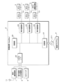
- FIG. 1 is a schematic diagram illustrating a configuration of an in-vehicle update system including an in-vehicle device according to Embodiment 1;
- FIG. FIG. 2 is a block diagram illustrating the physical configuration of the in-vehicle device.
- FIG. 4 is an explanatory diagram illustrating a flow (sequence) of processing by an in-vehicle device and an in-vehicle ECU for updating. 4 is a flowchart illustrating processing of a control unit of an in-vehicle device; 9 is a flowchart illustrating processing of a control unit of an in-vehicle device according to Embodiment 2;
- Patent Document 1 does not take into consideration the fact that when a downloaded control program is applied to an ECU to be updated, an operation check is performed when the control program is applied to the ECU to be updated. There is a problem.
- the purpose of the present disclosure is to provide an in-vehicle device or the like that can efficiently check the operation of an in-vehicle ECU to which the program is applied when performing processing to update the program of the in-vehicle ECU.
- An in-vehicle device is an in-vehicle update device that acquires an update program transmitted from an external server outside the vehicle and performs processing for updating a program of an in-vehicle ECU installed in the vehicle.
- a control unit that performs processing related to the update program, wherein the control unit acquires from the external server an operation check scenario for performing an operation check on an in-vehicle ECU to be updated when acquiring the update program;
- the acquired update program and the operation check scenario are output to the update target vehicle ECU, and based on the operation check scenario, the update target vehicle ECU is processed for operation check.
- the in-vehicle device (control unit) outputs an update program and an operation confirmation scenario to the in-vehicle ECU to be updated, and performs processing related to operation confirmation of the in-vehicle ECU to be updated based on the operation confirmation scenario.
- operation confirmation scenario execution procedures such as a processing sequence, a script, a command, or the like for operation confirmation performed by the in-vehicle device for the in-vehicle ECU to be updated are listed.
- An in-vehicle ECU that has acquired an update program and an operation check scenario from an in-vehicle device applies the acquired update program, and then performs operation in its own ECU based on the operation check scenario acquired together with the update program. Perform processing related to confirmation.
- the in-vehicle ECU and in-vehicle device to be updated will check the operation of the in-vehicle ECU to which the update program has been applied (in-vehicle ECU to be updated) based on the same operation check scenario. It is possible to efficiently check the operation under the actual environment of the vehicle in which it is mounted.
- control unit replaces an in-vehicle ECU other than the in-vehicle ECU to be updated based on the operation confirmation scenario, thereby replacing the in-vehicle ECU to be updated. Perform processing related to operation confirmation for
- the in-vehicle device performs processing related to the operation check for the in-vehicle ECU to be updated by substituting another in-vehicle ECU other than the in-vehicle ECU to be updated. can be done efficiently.
- the operation confirmation scenario includes a processing sequence in which the control unit substituting for the other in-vehicle ECU transmits data to the update target in-vehicle ECU; and a processing sequence in which the update target in-vehicle ECU to which the update program is applied transmits data to the other in-vehicle ECU replaced by the control unit.
- the operation confirmation scenario includes a processing sequence in which data transmission/reception is defined between an in-vehicle device substituting for another in-vehicle ECU and an in-vehicle ECU to which an update program is applied (an in-vehicle ECU to be updated).
- an in-vehicle ECU to be updated an in-vehicle ECU to be updated.
- the in-vehicle device that replaces the other in-vehicle ECU is based on the operation confirmation scenario. It will correspond. Therefore, by performing the operation check, it is possible to efficiently check the operation of the in-vehicle ECU to which the update program is applied without affecting the control of the vehicle itself.
- the operation check scenario includes determination information for determining a result of operation check for the in-vehicle ECU to be updated
- the control unit includes: A result of the operation confirmation is acquired by performing processing related to operation confirmation of the in-vehicle ECU to be updated, and the update target is determined based on the acquired operation confirmation result and the determination information included in the operation confirmation scenario. determines whether the update of the program in the in-vehicle ECU is successful or not.
- the operation check scenario includes determination information for determining the result of operation check for the in-vehicle ECU to be updated.
- the determination information includes, for example, the type of data expected to be transmitted from the in-vehicle ECU to be updated, the transmission cycle, the assumed usage rate of the CPU or memory of the in-vehicle ECU, and the operation confirmation data from the in-vehicle device. It includes the assumed value of the reply response when it is sent.
- the in-vehicle device control unit compares the determination information included in the operation check scenario with various values included in the result of the operation check to determine whether the update of the program in the in-vehicle ECU to be updated was successful. Whether (success or failure) can be efficiently determined.
- the control unit acquires, from the in-vehicle ECU to be updated, a result of a single diagnosis performed by the in-vehicle ECU to be updated based on the operation confirmation scenario, Based on the obtained result of the unit diagnosis, it is determined whether the update of the program in the in-vehicle ECU to be updated is successful.
- the in-vehicle ECU performs self-diagnosis processing within its own ECU based on the confirmation scenario obtained from the in-vehicle device.
- the self-diagnostic process is a diagnostic process that does not communicate with other in-vehicle ECU such as an in-vehicle device, and corresponds to a single diagnosis.
- the in-vehicle device acquires the result of the single diagnosis from the in-vehicle ECU to be updated, and based on the result of the single diagnosis, determines whether the program in the in-vehicle ECU to be updated has been successfully updated. It is possible to efficiently determine whether the update has succeeded (success or failure).
- the control unit uses a relay log collected when performing relay processing of communication between a plurality of in-vehicle ECUs mounted in the vehicle, to perform the external Complementing the operation check scenario obtained from a server, outputting the obtained update program and the complemented operation check scenario to the update target vehicle ECU, and based on the complemented operation check scenario, the update target vehicle ECU Perform processing related to operation confirmation for
- the in-vehicle device functions as an in-vehicle relay device such as a gateway or Ethernet SW that performs communication relay processing between a plurality of in-vehicle ECUs mounted in the vehicle.
- An in-vehicle device that functions as an in-vehicle relay device stores relay logs collected when performing relay processing in a storage unit. source address, destination address, message ID, etc.), payload information, transmission/reception frequency or cycle, and the like.
- the in-vehicle device (control unit) uses the relay log stored in the storage unit to supplement the operation confirmation scenario acquired from the external server by adding additional information, etc., so that the operation confirmation scenario is further adapted to the actual environment of the own vehicle. can be adapted.
- the operation check scenario complemented operation check scenario
- the control unit when the IG switch of the vehicle is turned off, the control unit performs processing related to operation confirmation of the in-vehicle ECU to be updated based on the operation confirmation scenario. conduct.
- the in-vehicle device performs processing related to the operation check based on the operation check scenario after the IG switch of the vehicle is turned off. It is possible to perform processing related to operation confirmation without being affected or affecting other in-vehicle ECUs.
- the control unit sends a sleep signal to an in-vehicle ECU other than the in-vehicle ECU to be updated to transition the other in-vehicle ECU to a sleep mode. After outputting the sleep signal, a process relating to operation confirmation of the in-vehicle ECU to be updated is performed based on the operation confirmation scenario.
- the in-vehicle device after outputting the sleep signal to the other in-vehicle ECUs other than the in-vehicle ECU to be updated, performs processing related to operation check based on the operation check scenario. As a result, the other in-vehicle ECU transitions to a sleep mode in which processing related to data transmission/reception is not performed. It is possible to perform processing related to operation confirmation.
- a program acquires an update program transmitted from an external server outside the vehicle, and transmits the update program to a computer that performs processing for updating a program of an in-vehicle ECU installed in the vehicle. is acquired from the external server, an operation check scenario for performing an operation check on the in-vehicle ECU to be updated is acquired from the external server, the acquired update program and the operation check scenario are output to the in-vehicle ECU to be updated, and Based on the operation confirmation scenario, a process for confirming the operation of the in-vehicle ECU to be updated is executed.
- the computer can function as an in-vehicle device that efficiently checks the operation of the in-vehicle ECU to which the control program is applied when executing the process of updating the control program of the in-vehicle ECU.
- a program update method acquires an update program transmitted from an external server outside the vehicle, and performs processing for updating a program of an in-vehicle ECU installed in the vehicle.
- acquires the update program acquire from the external server an operation check scenario for performing an operation check on the in-vehicle ECU to be updated, and output the acquired update program and the operation check scenario to the in-vehicle ECU to be updated. Then, based on the operation confirmation scenario, a process for confirming the operation of the in-vehicle ECU to be updated is executed.
- FIG. 1 is a schematic diagram showing the configuration of an in-vehicle update system S according to Embodiment 1.
- FIG. 2 is a block diagram showing the configuration of the in-vehicle device 2 and the like.
- the in-vehicle update system S includes an in-vehicle communication device 1 and an in-vehicle device 2 mounted in a vehicle C, and a package (update program, operation check scenario) acquired from a program providing device S1 connected via an outside network N, It is transmitted to an in-vehicle ECU 3 (Electronic Control Unit/in-vehicle control device) installed in the vehicle C.
- ECU 3 Electric Control Unit/in-vehicle control device
- the program providing device S1 is a computer such as a server connected to an external network N such as the Internet or a public network, and includes a storage unit S11 such as a RAM (Random Access Memory), a ROM (Read Only Memory), or a hard disk. It is equipped and corresponds to an external server outside the vehicle.
- a program or data for controlling the in-vehicle ECU 3 created by the manufacturer of the in-vehicle ECU 3 or the like is stored in the storage unit S11.
- the program or data is transmitted to the vehicle C as an update program and used to update the program or data of the in-vehicle ECU 3 mounted on the vehicle C, as will be described later.
- the program providing apparatus S1 (external server) configured in this way is also called an OTA (Over The Air) server.
- the in-vehicle ECU 3 installed in the vehicle acquires the update program transmitted by wireless communication from the program providing device S1, and applies the update program as a program to execute, thereby updating the program executed by the own ECU (repro). can do.
- the program will be described as including program code including control syntax and the like for the in-vehicle ECU 3 to perform processing, and an external file in which data referred to when executing the program code is described.
- the external file containing the program code and data is transmitted from the program providing apparatus S1 as, for example, an encrypted archive file.
- the program providing device S1 When transmitting an update program, the program providing device S1 generates a package including the update program, and transmits the generated package to the vehicle C.
- the package includes, for example, package information (campaign information) that is information on program update, information on the in-vehicle ECU to be updated (target information), an update program applied to the in-vehicle ECU to be updated, and the update program that is installed in the vehicle.
- package information that is information on program update
- information on the in-vehicle ECU to be updated target information
- an update program applied to the in-vehicle ECU to be updated includes, for example, package information (campaign information) that is information on program update, information on the in-vehicle ECU to be updated (target information), an update program applied to the in-vehicle ECU to be updated, and the update program that is installed in the vehicle.
- the vehicle C is equipped with an external communication device 1, an in-vehicle device 2, a display device 5, and a plurality of in-vehicle ECUs 3 for controlling various in-vehicle devices.
- the external communication device 1 and the in-vehicle device 2 are communicably connected by a harness such as a serial cable.
- the in-vehicle device 2 and the in-vehicle ECU 3 are communicably connected by an in-vehicle LAN 4 compatible with a communication protocol such as CAN (Control Area Network/registered trademark) or Ethernet (registered trademark).
- the vehicle-external communication device 1 includes a vehicle-external communication unit (not shown) and an input/output I/F (not shown) (interface) for communicating with the in-vehicle device 2 .
- the external communication unit is a communication device for wireless communication using a mobile communication protocol such as 3G, LTE, 4G, 5G, WiFi, etc., and a program providing device via an antenna 11 connected to the external communication unit. Sends and receives data to and from S1. Communication between the external communication device 1 and the program providing device S1 is performed via a public network or an external network such as the Internet.
- the input/output I/F of the vehicle-external communication device 1 is a communication interface for serial communication with the vehicle-mounted device 2, for example.
- the external communication device 1 and the in-vehicle device 2 communicate with each other via a harness such as a serial cable connected between the input/output I/Fs.
- the vehicle-external communication device 1 is separate from the vehicle-mounted device 2, and these devices are communicably connected via an input/output I/F or the like, but the present invention is not limited to this.
- the external communication device 1 may be built in the in-vehicle device 2 as one component of the in-vehicle device 2 .
- the in-vehicle device 2 includes a control unit 20, a storage unit 21, and an in-vehicle communication unit 23.
- the in-vehicle device 2 acquires from the in-vehicle communication device 1 the update program (package) that the in-vehicle communication device 1 has received from the program providing device S1 by wireless communication, and transmits the update program via the in-vehicle LAN 4 to a predetermined in-vehicle ECU 3 (update It is configured to transmit to the target in-vehicle ECU 3). That is, the in-vehicle device 2 functions as an OTA master that controls program update in the in-vehicle ECU 3 to be updated.
- the in-vehicle device 2 controls a plurality of system buses (segments) such as a control system in-vehicle ECU 3, a safety system in-vehicle ECU 3, and a body system in-vehicle ECU 3. It is a gateway (in-vehicle relay device) that relays communication between That is, the in-vehicle device 2 functions as a CAN gateway in relaying the CAN protocol, and functions as a layer 2 switch or a layer 3 switch in relaying the TCP/IP protocol.
- system buses such as a control system in-vehicle ECU 3, a safety system in-vehicle ECU 3, and a body system in-vehicle ECU 3.
- the in-vehicle device 2 also serves as a power distribution device that distributes and relays power output from a power supply device such as a secondary battery, and supplies power to in-vehicle devices such as actuators connected to the device itself. It may be a functioning PLB (Power Lan Box). Alternatively, the in-vehicle device 2 may be configured as a functional part of a body ECU that controls the vehicle C as a whole. Alternatively, the in-vehicle device 2 may be an integrated ECU configured by a central control device such as a vehicle computer, for example, and performing overall control of the vehicle.
- a power supply device such as a secondary battery
- PLB Power Lan Box
- the in-vehicle device 2 may be configured as a functional part of a body ECU that controls the vehicle C as a whole.
- the in-vehicle device 2 may be an integrated ECU configured by a central control device such as a vehicle computer, for example, and performing overall control of the vehicle.
- the control unit 20 is configured by a CPU (Central Processing Unit) or MPU (Micro Processing Unit), etc. By reading and executing a control program P (program product) and data stored in advance in the storage unit 21, Various control processing and arithmetic processing are performed.
- a control program P program product
- the storage unit 21 is composed of a volatile memory element such as RAM (Random Access Memory) or a non-volatile memory element such as ROM (Read Only Memory), EEPROM (Electrically Erasable Programmable ROM) or flash memory, A control program and data to be referred to during processing are stored in advance.
- the control program P (program product) stored in the storage unit 21 may be the control program P (program product) read from the recording medium 211 readable by the in-vehicle device 2 .
- the control program may be downloaded from an external computer (not shown) connected to a communication network (not shown) and stored in the storage unit 21 .
- the storage unit 21 stores vehicle configuration information in which the configuration information of each in-vehicle ECU installed in the vehicle is aggregated.
- vehicle configuration information includes, for example, the production number (serial number) of each in-vehicle ECU, the ECU part number (model number), the software part number, the current version of the program, the old version, the number of operation surfaces, the operation surface, MAC (Media Access Control) Address, IP address, last update completion date, repro status and VIN (vehicle identification number).
- the storage unit 21 stores relay route information (routing table) used for performing relay processing for communication between the in-vehicle ECUs 3 or communication between the in-vehicle ECUs 3 and the external server 100 .
- the format of the relay route information is determined based on the communication protocol.
- the relay route information for CAN includes the message identifier (CAN-ID) included in the CAN message and the relay destination (I / O port number of the CAN communication unit 232) associated with the CAN-ID. including.
- the TCP/IP relay route information includes the destination address (MAC address or IP address) included in the IP packet and the relay destination associated with the destination address (Ethernet communication unit 231 physical port number).
- the relay route information (routing table) may be included in the vehicle configuration information.
- the storage unit 21 further stores relay logs collected when performing relay processing of communication between a plurality of in-vehicle ECUs.
- the relay log includes, for example, data such as header information (source address, destination address, message ID, etc.), payload information, transmission/reception frequency or cycle of the Ether frame or CAN message to be relayed.
- the data may be associated with a time stamp indicating communication history.
- the relay log can be used as data indicating the communication state and communication history in the actual operating environment (actual vehicle environment) of the vehicle in which the in-vehicle device is mounted.
- the input/output I/F 22 is, like the input/output I/F of the external communication device 1, a communication interface for serial communication, for example.
- the in-vehicle device 2 is communicably connected to the external communication device 1, the display device 5 (HMI device), and the IG switch 6 for starting and stopping the vehicle C via the input/output I/F 22 .
- the in-vehicle communication unit 23 is an input/output interface (CAN transceiver, Ethernet PHY unit) using a communication protocol such as CAN (Control Area Network), CAN-FD (CAN with Flexible Data Rate), or Ethernet (registered trademark). It functions as a communication unit for communication between the in-vehicle device 2 and the in-vehicle ECU 3 .
- a plurality of in-vehicle communication units 23 are provided, and each communication line 41 (Ethernet cable, CAN bus) constituting the in-vehicle network 4, that is, each bus is connected to each in-vehicle communication unit 23 .
- the in-vehicle network 4 is divided into a plurality of buses (segments), and the in-vehicle ECU 3 is connected to each segment according to the function of the in-vehicle ECU 3. good.
- the control unit 20 of the in-vehicle device 2 communicates with the in-vehicle ECU 3 connected to the in-vehicle network 4 via the in-vehicle communication unit 23 .
- the vehicle-mounted ECU 3 includes a control unit (not shown), a storage unit (not shown), and an in-vehicle communication unit (not shown), similar to the vehicle-mounted device 2 .
- the storage unit is composed of volatile memory elements such as RAM (Random Access Memory) or non-volatile memory elements such as ROM (Read Only Memory), EEPROM (Electrically Erasable Programmable ROM), or flash memory.
- RAM Random Access Memory
- ROM Read Only Memory
- EEPROM Electrical Erasable Programmable ROM
- flash memory flash memory
- a program or data for the ECU 3 is stored. This program or data is an object to be updated by an update program transmitted from the program providing device and relayed by the in-vehicle device 2 .
- An in-vehicle communication unit of the in-vehicle ECU 3 is configured by, for example, a CAN transceiver or an Ethernet PHY unit, like the in-vehicle device 2, and communicates with the in-vehicle device 2 via the in-vehicle communication unit.
- the display device 5 is, for example, an HMI (Human Machine Interface) device such as a car navigation display.
- the display device 5 is communicably connected to the input/output I/F 22 of the in-vehicle device 2 by a harness such as a serial cable. Data or information output from the control unit 20 of the in-vehicle device 2 via the input/output I/F 22 is displayed on the display device 5 .
- HMI Human Machine Interface
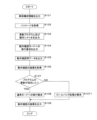
- FIG. 3 is an explanatory diagram illustrating the flow (sequence) of processing by the in-vehicle device 2 and the in-vehicle ECU 3 for updating.
- each process of the program providing device S1 (OTA server), the in-vehicle device 2 (OTA master), and the in-vehicle ECU 3 to be updated (target ECU) A sequence is explained.
- the in-vehicle device 2 outputs (transmits) the vehicle configuration information of the vehicle C (own vehicle) to the program providing device S1 (S01).
- the in-vehicle device 2 routinely acquires program information, type information, etc. applied to the in-vehicle ECU 3 from each in-vehicle ECU 3, and generates and stores vehicle configuration information by aggregating these information.
- the in-vehicle device 2 may include VIN (Vehicle Identification Number) in the vehicle configuration information.
- the program providing device S1 generates a package including the update program and the operation confirmation scenario (S02).
- the program providing device S1 generates a package based on the vehicle configuration information acquired from the in-vehicle device 2.
- FIG. The package contains package information (campaign information) that is information on program update, information on the in-vehicle ECU 3 to be updated (target information), an update program applied to the in-vehicle ECU 3 to be updated, and the update program installed in the vehicle.
- An operation confirmation scenario for confirming the operation when applied to the ECU 3 is included.
- execution procedures such as processing sequences, scripts, commands, etc. for operation confirmation performed by the in-vehicle device 2 for the in-vehicle ECU 3 to be updated are listed.
- the operation confirmation scenario further includes a processing sequence for operation confirmation performed by the in-vehicle ECU 3 to be updated, and judgment information for verifying (success/failure judgment) the result of operation confirmation by the in-vehicle device 2 and the in-vehicle ECU 3 to be updated.
- the program providing device S1 can generate an operation confirmation scenario suitable for the actual environment of the vehicle C in which the in-vehicle device 2 is mounted.
- the program providing device S1 outputs (transmits) the generated package to the in-vehicle device 2 (S03).
- the in-vehicle device 2 stores the package acquired (received) from the program providing device S1 in the storage unit S11 (S04).
- the in-vehicle device 2 may shift (transition) from the normal mode (state during normal operation of the vehicle C) to the update mode by acquiring the package from the program providing device S1.
- the in-vehicle device 2 outputs (transmits) the update program and the operation check scenario included in the package to the in-vehicle ECU 3 to be updated (S05).
- the in-vehicle ECU 3 to be updated stores the update program and the operation confirmation scenario obtained (received) from the in-vehicle device 2 in the storage unit (S06).
- the in-vehicle ECU 3 to be updated receives the update program and the operation confirmation scenario from the in-vehicle device 2, thereby shifting (transitioning) to the update mode.
- the storage unit of the in-vehicle ECU 3 to be updated stores a first storage area that stores the currently applied program (current version program) and a previously applied program (old version program). and a second storage area.
- the in-vehicle ECU 3 to be updated stores the update program and the operation check scenario acquired from the in-vehicle device 2 in the second storage area, thereby performing the update without overwriting the current version of the program stored in the first storage area. It may be one that saves (stores) a program or the like.
- the in-vehicle ECU 3 to be updated can reliably perform rollback processing to return to the old version of the program by providing a dual storage unit having a first storage area and a second storage area.
- the in-vehicle device 2 issues an activation request (instruction to apply the update program) to the in-vehicle ECU 3 to be updated (S07).
- the in-vehicle device 2 transmits a control signal (activation request signal) to the in-vehicle ECU 3 to be updated, for example, to make an activation request (instruction to apply the update program).
- the activation request is triggered by turning off the IG switch 6, the activation request is not limited to this. may be
- the in-vehicle ECU 3 to be updated switches from the currently applied program to the update program in response to the activation request from the in-vehicle device 2 (S08).
- the in-vehicle ECU 3 to be updated outputs (transmits) information (activation result) indicating switching to the update program to the in-vehicle device 2 (S09).
- the in-vehicle ECU 3 to be updated has, as described above, a two-sided storage unit having a first storage area and a second storage area, and validating (activating) the second storage area in which the update program is stored. switch to the update program.
- the in-vehicle device 2 requests the in-vehicle ECU 3 to be updated to switch to the operation check mode according to the operation check scenario stored in the storage unit 21 (S10).
- the in-vehicle device 2 requests the transition to the operation check mode by, for example, transmitting a control signal (an operation check mode transition signal) to the in-vehicle ECU 3 to be updated.
- the in-vehicle ECU 3 to be updated shifts (transitions) to the operation confirmation mode in response to a request from the in-vehicle device 2 to shift to the operation confirmation mode (S11).
- the in-vehicle ECU 3 to be updated which has shifted to the operation check mode, executes the update program based on the operation check scenario.
- the operation confirmation scenario includes a sequence relating to self-diagnosis processing (individual diagnosis) performed within the own ECU (inside the in-vehicle ECU 3 to be updated).
- the in-vehicle ECU 3 to be updated, which has shifted to the operation check mode performs self-diagnosis processing (individual diagnosis) performed within its own ECU based on the operation check scenario.
- the in-vehicle device 2 outputs (transmits) operation check data to the update target in-vehicle ECU 3 based on the operation check scenario (S12).
- the in-vehicle device 2 outputs the operation confirmation data to the in-vehicle ECU 3 to be updated
- the in-vehicle device 2 replaces another in-vehicle ECU 3 with which the in-vehicle ECU 3 to be updated normally communicates.
- the in-vehicle device 2 substitutes for another in-vehicle ECU 3
- the in-vehicle device 2 may transmit an Ethernet frame having the IP address of the other in-vehicle ECU 3 as a source address.
- the in-vehicle device 2 may transmit a CAN message including the CAN-ID used by the other in-vehicle ECU 3 .
- the in-vehicle ECU 3 to be updated outputs (transmits) response data to the in-vehicle device 2 according to the operation confirmation data transmitted from the in-vehicle device 2 substituting for the other in-vehicle ECU 3 (S13).
- a processing sequence of data transmission/reception between the in-vehicle device 2 substituting for another in-vehicle ECU 3 and the update target in-vehicle ECU 3 is performed based on an operation check scenario.
- the control over the sensor or actuator connected to the in-vehicle ECU 3 to be updated may be omitted or disabled.
- the in-vehicle device 2 and the in-vehicle ECU 3 to be updated may store response values in the processing sequence by transmission and reception of these data, or measured values (actual values) such as communication traffic volume, and store them as operation check results. .
- the in-vehicle ECU 3 to be updated outputs (sends) to the in-vehicle device 2 the result of the unit diagnosis and the result of operation confirmation by data transmission/reception with the in-vehicle device 2 (S14).
- the operation check scenario includes unit diagnosis judgment information for judging the result of the unit diagnosis.
- the unit diagnostic determination information is expected values such as a process list, CPU usage, and memory usage generated in the in-vehicle ECU 3 to be updated when the update program is executed (activated).
- the in-vehicle ECU 3 to be updated judges the result of the single diagnosis by comparing various actual measurement values in the result of the single diagnosis with various expected values in the determination information for single diagnosis. If the actual measurement value in the result of the unit diagnosis matches the expected value in the determination information for unit diagnosis, the in-vehicle ECU 3 to be updated determines that the result of the unit diagnosis performed based on the operation check scenario is positive (program update is successful). ). If the measured value in the result of the unit diagnosis does not match the expected value in the determination information for unit diagnosis, the in-vehicle ECU 3 to be updated determines that the result of the unit diagnosis performed based on the operation confirmation scenario is negative (program update failed). ).
- the in-vehicle device 2 stores, in the storage unit 21, the result of the operation check by data transmission/reception with the in-vehicle ECU 3 to be updated (S15).
- the in-vehicle device 2 stores in the storage unit 21 the result of the operation check output from the in-vehicle ECU 3 to be updated. Furthermore, the in-vehicle device 2 also stores in the storage unit 21 the result of the operation confirmation verified by the own device.
- the in-vehicle device 2 compares the determination information included in the operation check scenario with various values (measured values, actual values) included in the result of the operation check. , whether or not the update of the program in the in-vehicle ECU 3 to be updated has succeeded (success or failure) is determined (S16).
- the determination information includes, for example, an expected value regarding response data from the update target vehicle ECU 3 to the operation confirmation data transmitted from the vehicle device 2 substituting for another vehicle ECU 3 to the update target vehicle ECU 3. .
- the expected values for the response data are, for example, presence/absence of response data, type (header information), data length, payload information, and return response value of response data.
- the in-vehicle device 2 In data transmission/reception with the in-vehicle ECU 3 to be updated, the in-vehicle device 2 includes the presence or absence of response data from the in-vehicle ECU 3 to be updated, measured values such as data length or reply response value, and determination information (response The result of the operation check is verified by comparing with the expected value of data). If the response data from the in-vehicle ECU 3 to be updated matches the determination information, that is, the expected value defined in the operation check scenario (expected value regarding the response data), the in-vehicle device 2 performs the operation check based on the operation check scenario. It is determined that the result of the operation check is affirmative (program update is successful).
- the in-vehicle device 2 If the response data from the in-vehicle ECU 3 to be updated does not match the determination information, that is, the expected value defined in the operation check scenario (expected value related to the response data), the in-vehicle device 2 performs the operation check based on the operation check scenario. It is determined that the result of the operation check is negative (program update failed).
- the in-vehicle device 2 determines whether or not the update of the program in the in-vehicle ECU 3 to be updated is successful based on the result of the single diagnosis acquired from the in-vehicle ECU 3 to be updated and the result of the operation check by data transmission/reception with the in-vehicle device 2. (success or failure). That is, the in-vehicle device 2 receives the result of operation check related to the transmission and reception of the operation check data from its own device side, the result of the operation check related to the transmission and reception of the operation check data from the in-vehicle ECU 3 side, and the single diagnosis in the in-vehicle ECU 3.
- the success or failure determination of the update of the program in vehicle-mounted ECU3 of update object is performed.
- the in-vehicle device 2 determines that the update of the program in the in-vehicle ECU 3 to be updated has succeeded.
- the in-vehicle device 2 requests the in-vehicle ECU 3 to be updated to switch to the normal mode (S17).
- the in-vehicle ECU 3 to be updated shifts (transitions) to the normal mode in response to the request from the in-vehicle device 2 to shift to the normal mode (S18).
- the in-vehicle ECU 3 to be updated receives the request to shift to the normal mode from the in-vehicle device 2, the update of the program in the in-vehicle ECU 3 to be updated is completed, and the in-vehicle ECU 3 performs the operation when the vehicle C travels. It shifts (transitions) to a state (normal mode) in which control is performed in a normal manner.
- the in-vehicle device 2 determines that the update of the program in the in-vehicle ECU 3 to be updated has failed. When it is determined that the update of the program has failed, the in-vehicle device 2 may request the in-vehicle ECU 3 to be updated to perform rollback processing. The in-vehicle device 2 may decide whether to take either the rollback process or the transition to the degeneracy mode based on these three confirmation results. The in-vehicle device 2 may output, for example, the display device 5 to notify the operator of the vehicle C that the update of the program has failed.
- the in-vehicle device 2 outputs (transmits) the result of the operation check based on the operation check scenario to the program providing device S1 (S19).
- the program providing device S1 that has obtained the result of the operation check output from the in-vehicle device 2 stores the result in the storage unit S11 of its own device. Accordingly, it is possible to harmonize (synchronize) the information regarding the program update based on the package between the in-vehicle device 2 and the program providing device S1.
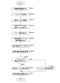
- FIG. 4 is a flowchart illustrating the processing of the control unit 20 of the in-vehicle device 2.
- the control unit 20 of the in-vehicle device 2 routinely performs the following processing, for example, when the vehicle C is in an activated state (the IG switch 6 is on).
- the control unit 20 of the in-vehicle device 2 outputs (transmits) vehicle configuration information of the vehicle C (own vehicle) to the program providing device S1 (S101).
- the output of the vehicle configuration information to the program providing device S1 by the control unit 20 of the in-vehicle device 2 is not limited to when performing the program update processing for the in-vehicle ECU 3, and the output of the vehicle configuration information is performed constantly. There may be. That is, the control unit 20 of the in-vehicle device 2 steadily or periodically acquires program information and model information applied to the in-vehicle ECUs 3 from all the in-vehicle ECUs 3 mounted in the vehicle C (own vehicle). , and stores the acquired and aggregated information as vehicle configuration information.
- the control unit 20 of the in-vehicle device 2 may regularly or periodically provide the program providing device S1 with the vehicle configuration information including the VIN.
- the program providing device S1 identifies the target vehicle C based on the vehicle configuration information including the VIN, and creates a package corresponding to the identified vehicle C.
- the package created by the program providing device S1 includes package information (campaign information) that is information on program update, information on the in-vehicle ECU 3 to be updated (target information), an update program (update data), and an operation check scenario. .
- the control unit 20 of the in-vehicle device 2 acquires the package containing the update program and the operation check scenario from the program providing device S1 (S102).
- the control unit 20 of the in-vehicle device 2 communicates with the program providing device S1 via the external communication device 1 and acquires the package from the program providing device S1.
- the control unit 20 of the in-vehicle device 2 stores the acquired package in the storage unit 21 .
- the control unit 20 of the in-vehicle device 2 outputs the update program and the operation confirmation scenario to the in-vehicle ECU 3 to be updated (S103).
- the operation check scenario is shared by the in-vehicle device 2 and the in-vehicle ECU 3 to be updated. That is, the in-vehicle device 2 and the in-vehicle ECU 3 to be updated can perform the operation check process based on the same operation check scenario.
- the control unit 20 of the in-vehicle device 2 outputs an update program and an operation check scenario to the in-vehicle ECU 3 to be updated, and outputs an activation request indicating that the update program is to be applied to the in-vehicle ECU 3. There may be.
- the control unit 20 of the in-vehicle device 2 outputs a request to shift to the operation check mode to the in-vehicle ECU 3 to be updated (S104).
- the in-vehicle ECU 3 to be updated that acquires (receives) the request to shift to the operation check mode from the in-vehicle device 2 starts executing the operation check based on the operation check scenario when applying the update program.
- the control unit 20 of the in-vehicle device 2 outputs operation confirmation data to the in-vehicle ECU 3 to be updated based on the operation confirmation scenario (S105).
- the vehicle-mounted ECU 3 to be updated performs data communication with other vehicle-mounted ECUs 3 instead of the vehicle-mounted device 2 .
- the in-vehicle device 2 replaces the other in-vehicle ECU 3 so as to simulate the operation mode of the other in-vehicle ECU 3 .
- in-vehicle ECU3 of update object of operation check mode performs a series of processing sequences including transmission and reception of data between in-vehicle devices 2 which replaced other in-vehicle ECU3.
- the controller 20 of the in-vehicle device 2 outputs operation confirmation data to the update target vehicle ECU 3, and the update target vehicle ECU 3 similarly outputs response data based on the operation confirmation scenario. That is, the control unit 20 of the in-vehicle device 2 and the in-vehicle ECU 3 to be updated start transmitting and receiving data in accordance with the actual vehicle environment according to the same operation confirmation scenario.
- the control unit 20 of the in-vehicle device 2 acquires the result of operation confirmation according to the operation confirmation scenario (S106).
- the in-vehicle ECU 3 to be updated outputs to the in-vehicle device 2 the result of the unit diagnosis and the result of the operation check regarding the transmission and reception of the data for operation check from the own ECU side.
- the control unit 20 of the in-vehicle device 2 acquires these results from the in-vehicle ECU 3 to be updated. Furthermore, the control unit 20 of the in-vehicle device 2 acquires the result of the operation check regarding the transmission and reception of the operation check data from the own device side.
- various measured values are stored in the storage unit 21 of the in-vehicle device 2 in the operation check performed based on the operation check scenario.
- the control unit 20 of the in-vehicle device 2 acquires the result of the operation check regarding the transmission and reception of the operation check data from the own device by referring to the storage unit 21 of the own device. That is, the control unit 20 of the in-vehicle device 2 acquires these three operation confirmation results.
- the control unit 20 of the in-vehicle device 2 determines whether or not the update of the program in the in-vehicle ECU 3 to be updated has succeeded (S107).
- the operation confirmation scenario includes judgment information for judging the result of operation confirmation.
- the control unit 20 of the in-vehicle device 2 determines whether or not the program has been successfully updated by comparing various actual measurement values obtained as a result of the operation check with the expected value included in the determination information. For example, when all measured values are within the range of expected values, the control unit 20 of the in-vehicle device 2 determines that the program has been successfully updated.
- the control unit 20 of the in-vehicle device 2 determines that the update of the program has failed if, for example, all the measured values do not fall within the range of the expected values.
- the control unit 20 of the in-vehicle device 2 requests the in-vehicle ECU 3 to be updated to switch to the normal mode (S108).
- the control unit 20 of the in-vehicle device 2 for example, outputs a control signal (normal mode transition signal) to the in-vehicle ECU 3 to be updated, thereby requesting the transition to the normal mode.
- the in-vehicle ECU 3 to be updated that receives the request to shift to the normal mode shifts to the normal mode.
- the control unit 20 of the in-vehicle device 2 requests the in-vehicle ECU 3 to be updated to perform rollback processing (S1071 ).
- the control unit 20 of the in-vehicle device 2 requests rollback processing by, for example, outputting a control signal (rollback signal) to the in-vehicle ECU 3 to be updated.
- the control unit 20 of the in-vehicle device 2 may decide whether to request the rollback process or shift to the degeneracy mode according to the mode of the result of the operation check. good.
- the control unit 20 of the in-vehicle device 2 outputs (transmits) the result of the operation check based on the operation check scenario to the program providing device S1 (S109).
- the control unit 20 of the in-vehicle device 2 outputs (transmits) the result of the operation check based on the operation check scenario to the program providing device S1 via the external communication device 1 .
- the control unit 20 of the in-vehicle device 2 may output the result of operation confirmation based on the operation confirmation scenario to the display device 5 and notify the operator of the vehicle C or the like of the result.
- the in-vehicle ECU 3 to be updated and the in-vehicle device 2 perform operation check of the in-vehicle ECU 3 to which the update program is applied (in-vehicle ECU 3 to be updated) based on the same operation check scenario. It is possible to efficiently check the operation of the vehicle C in which the ECU 3 and the in-vehicle device 2 are mounted under the actual environment.
- the in-vehicle device 2 substitutes for another in-vehicle ECU 3 other than the in-vehicle ECU 3 to be updated. It becomes possible to perform transmission, and it is possible to efficiently check the operation of the vehicle C in accordance with the actual environment.
- FIG. 5 is a flowchart illustrating processing of the control unit 20 of the in-vehicle device 2 according to the second embodiment.
- the control unit 20 of the in-vehicle device 2 outputs (transmits) vehicle configuration information of the vehicle C (own vehicle) to the program providing device S1 (S201).
- the control unit 20 of the in-vehicle device 2 acquires the package including the update program and the operation check scenario from the program providing device S1 (S202).
- the control unit 20 of the in-vehicle device 2 performs the processes of S201 and S202 in the same manner as the processes S101 and S102 of the first embodiment.
- the control unit 20 of the in-vehicle device 2 complements the operation check scenario using the relay log collected when the communication relay processing was performed between the multiple in-vehicle ECUs 3 (S203).
- the in-vehicle device 2 includes a plurality of in-vehicle communication units 23 and functions as an in-vehicle relay device that relays communication between the in-vehicle ECUs 3 connected to these in-vehicle communication units 23 .
- the control unit 20 of the in-vehicle device 2 stores a relay log in the storage unit 21 based on the relayed data (Etherframe, CAN message).
- the relay log includes, for example, header information (source address, destination address, message ID, etc.), payload information, transmission/reception frequency or cycle, etc. of the Ethernet frame or CAN message to be relayed. is data indicating the communication state in the actual operating environment (actual vehicle environment) of the vehicle C in which the is mounted.
- the control unit 20 of the in-vehicle device 2 uses the relay log to add or modify the sequence related to data transmission/reception included in the operation check scenario, so that the operation check scenario generated by the program providing device S1 is further processed in the actual vehicle environment.
- Complement according to The control unit 20 of the in-vehicle device 2 uses the complemented operation confirmation scenario to perform subsequent processing. That is, in subsequent processes, the operation check scenario used by the control unit 20 of the in-vehicle device 2 and the in-vehicle ECU 3 to be updated is the operation check scenario complemented using the relay log.
- the control unit 20 of the in-vehicle device 2 outputs the update program and the operation confirmation scenario to the in-vehicle ECU 3 to be updated (S204).
- the control unit 20 of the in-vehicle device 2 performs the process of S204 in the same manner as the process S103 of the first embodiment.
- the control unit 20 of the in-vehicle device 2 outputs a sleep signal to the other in-vehicle ECUs 3 other than the in-vehicle ECU 3 to be updated (S205).
- the control unit 20 of the in-vehicle device 2 can grasp all the in-vehicle ECUs 3 installed in the vehicle C (own vehicle) by referring to, for example, the vehicle configuration information or the routing table used for relay processing. .
- the control unit 20 of the in-vehicle device 2 specifies other in-vehicle ECUs 3 other than the in-vehicle ECU 3 to be updated among all the in-vehicle ECUs 3 installed in the vehicle C (own vehicle).
- the control unit 20 of the in-vehicle device 2 outputs (transmits) a sleep signal for transitioning to the sleep mode to the specified other in-vehicle ECU 3 .
- Other in-vehicle ECU3 which received the sleep signal stops processing, such as transmission and reception of data, by changing to sleep mode. Thereby, it is possible to perform the process of updating the program to the in-vehicle ECU 3 to be updated while preventing the other in-vehicle ECU 3 other than the in-vehicle ECU 3 to be updated from being affected.
- the control unit 20 of the in-vehicle device 2 outputs a sleep signal
- the present invention is not limited to this. Communication of other in-vehicle ECU3 may be restricted.
- the control unit 20 of the in-vehicle device 2 outputs a request to shift to the operation check mode to the in-vehicle ECU 3 to be updated (S206).
- the control unit 20 of the in-vehicle device 2 outputs operation confirmation data to the in-vehicle ECU 3 to be updated based on the operation confirmation scenario (S207).
- the control unit 20 of the in-vehicle device 2 acquires the result of operation confirmation based on the operation confirmation scenario (S208).
- the control unit 20 of the in-vehicle device 2 determines whether or not the update of the program in the in-vehicle ECU 3 to be updated has succeeded (S209).
- the control unit 20 of the in-vehicle device 2 requests the in-vehicle ECU 3 to be updated to switch to the normal mode (S210).
- the update of the program fails (S209: NO), that is, when the update of the program fails, the control unit 20 of the in-vehicle device 2 requests the in-vehicle ECU 3 to be updated to perform rollback processing (S2091 ).
- the control unit 20 of the in-vehicle device 2 outputs (transmits) the result of the operation check based on the operation check scenario to the program providing device S1 (S211).
- the control unit 20 of the in-vehicle device 2 performs the processing from S206 to S211 in the same manner as the processing from S104 to S109 of the first embodiment.
- the in-vehicle device 2 supplements the operation confirmation scenario acquired from the external server by adding, etc., using the relay log at the time of performing the relay processing.
- the suitability of verification scenarios can be improved.
- the operation check scenario complemented operation check scenario
- the accuracy of the operation check when the update program is applied to the in-vehicle ECU 3 to be updated is improved. can be improved.
Landscapes
- Engineering & Computer Science (AREA)
- Software Systems (AREA)
- General Engineering & Computer Science (AREA)
- Theoretical Computer Science (AREA)
- Computer Security & Cryptography (AREA)
- Physics & Mathematics (AREA)
- General Physics & Mathematics (AREA)
- Mechanical Engineering (AREA)
- Stored Programmes (AREA)
Priority Applications (2)
| Application Number | Priority Date | Filing Date | Title |
|---|---|---|---|
| CN202280066175.5A CN118043234A (zh) | 2021-10-12 | 2022-09-27 | 车载装置、程序以及程序的更新方法 |
| US18/699,675 US20240403027A1 (en) | 2021-10-12 | 2022-09-27 | In-vehicle device, program, and method for updating program |
Applications Claiming Priority (2)
| Application Number | Priority Date | Filing Date | Title |
|---|---|---|---|
| JP2021167466A JP7652044B2 (ja) | 2021-10-12 | 2021-10-12 | 車載装置、プログラム及び、プログラムの更新方法 |
| JP2021-167466 | 2021-10-12 |
Publications (1)
| Publication Number | Publication Date |
|---|---|
| WO2023063068A1 true WO2023063068A1 (ja) | 2023-04-20 |
Family
ID=85988509
Family Applications (1)
| Application Number | Title | Priority Date | Filing Date |
|---|---|---|---|
| PCT/JP2022/035814 Ceased WO2023063068A1 (ja) | 2021-10-12 | 2022-09-27 | 車載装置、プログラム及び、プログラムの更新方法 |
Country Status (4)
| Country | Link |
|---|---|
| US (1) | US20240403027A1 (https=) |
| JP (2) | JP7652044B2 (https=) |
| CN (1) | CN118043234A (https=) |
| WO (1) | WO2023063068A1 (https=) |
Families Citing this family (2)
| Publication number | Priority date | Publication date | Assignee | Title |
|---|---|---|---|---|
| JP7605176B2 (ja) * | 2022-04-21 | 2024-12-24 | トヨタ自動車株式会社 | 制御システム、更新制御方法、および、更新制御プログラム |
| JP7673719B2 (ja) * | 2022-10-05 | 2025-05-09 | トヨタ自動車株式会社 | モバイル端末、ソフトウェア配信システム |
Citations (5)
| Publication number | Priority date | Publication date | Assignee | Title |
|---|---|---|---|---|
| JP2016060388A (ja) * | 2014-09-18 | 2016-04-25 | 株式会社オートネットワーク技術研究所 | プログラム送信システム及びプログラム送信装置 |
| JP2019074800A (ja) * | 2017-10-12 | 2019-05-16 | 日立オートモティブシステムズ株式会社 | 情報更新装置、情報更新方法 |
| JP2020062936A (ja) * | 2018-10-16 | 2020-04-23 | 株式会社オートネットワーク技術研究所 | 車載更新装置、更新処理プログラム及び、プログラムの更新方法 |
| JP2021022018A (ja) * | 2019-07-24 | 2021-02-18 | 株式会社日立製作所 | サーバ、ソフトウェア更新システム、およびソフトウェア更新装置 |
| JP2021158517A (ja) * | 2020-03-26 | 2021-10-07 | 株式会社オートネットワーク技術研究所 | 車載情報処理装置、情報処理方法及びクライアントプログラム |
-
2021
- 2021-10-12 JP JP2021167466A patent/JP7652044B2/ja active Active
-
2022
- 2022-09-27 CN CN202280066175.5A patent/CN118043234A/zh active Pending
- 2022-09-27 WO PCT/JP2022/035814 patent/WO2023063068A1/ja not_active Ceased
- 2022-09-27 US US18/699,675 patent/US20240403027A1/en active Pending
-
2024
- 2024-11-19 JP JP2024201664A patent/JP7835261B2/ja active Active
Patent Citations (5)
| Publication number | Priority date | Publication date | Assignee | Title |
|---|---|---|---|---|
| JP2016060388A (ja) * | 2014-09-18 | 2016-04-25 | 株式会社オートネットワーク技術研究所 | プログラム送信システム及びプログラム送信装置 |
| JP2019074800A (ja) * | 2017-10-12 | 2019-05-16 | 日立オートモティブシステムズ株式会社 | 情報更新装置、情報更新方法 |
| JP2020062936A (ja) * | 2018-10-16 | 2020-04-23 | 株式会社オートネットワーク技術研究所 | 車載更新装置、更新処理プログラム及び、プログラムの更新方法 |
| JP2021022018A (ja) * | 2019-07-24 | 2021-02-18 | 株式会社日立製作所 | サーバ、ソフトウェア更新システム、およびソフトウェア更新装置 |
| JP2021158517A (ja) * | 2020-03-26 | 2021-10-07 | 株式会社オートネットワーク技術研究所 | 車載情報処理装置、情報処理方法及びクライアントプログラム |
Also Published As
| Publication number | Publication date |
|---|---|
| JP2025020454A (ja) | 2025-02-12 |
| US20240403027A1 (en) | 2024-12-05 |
| JP7652044B2 (ja) | 2025-03-27 |
| CN118043234A (zh) | 2024-05-14 |
| JP2023057798A (ja) | 2023-04-24 |
| JP7835261B2 (ja) | 2026-03-25 |
Similar Documents
| Publication | Publication Date | Title |
|---|---|---|
| JP7160111B2 (ja) | 監視装置、監視プログラム及び監視方法 | |
| JP6780724B2 (ja) | 車載更新装置、更新処理プログラム及び、プログラムの更新方法 | |
| JP7192415B2 (ja) | プログラム更新システム及び更新処理プログラム | |
| CN113631429B (zh) | 车载更新装置、更新处理程序及程序的更新方法 | |
| CN113498509B (zh) | 替代装置、替代控制程序产品及替代方法 | |
| JP7835261B2 (ja) | 車載装置、プログラム及び、プログラムの更新方法 | |
| WO2018185994A1 (ja) | 制御装置、転送方法、およびコンピュータプログラム | |
| JP7310570B2 (ja) | 車載更新装置、プログラム及び、プログラムの更新方法 | |
| JP7415756B2 (ja) | 車載装置、情報処理方法及びコンピュータプログラム | |
| JP7331818B2 (ja) | 車載更新装置、更新処理プログラム及び、プログラムの更新方法 | |
| JP2022041194A (ja) | 車載機器、情報生成方法、情報生成プログラム、および、車両 | |
| WO2024219242A1 (ja) | 冗長系ecu、プログラム、及び情報処理方法 | |
| JP7690912B2 (ja) | 車載装置、プログラム、及びプログラムの更新方法 | |
| JP7722200B2 (ja) | 中継装置、プログラム及び、プログラムの更新方法 | |
| WO2025084126A1 (ja) | 車載装置、更新処理方法、及び車載更新システム | |
| WO2023106072A1 (ja) | 車載装置、プログラム、プログラムの更新方法、及び車載更新システム | |
| WO2025225286A1 (ja) | マスタ装置、車両システム、ソフトウェアの更新方法及びソフトウェアの更新制御プログラム |
Legal Events
| Date | Code | Title | Description |
|---|---|---|---|
| 121 | Ep: the epo has been informed by wipo that ep was designated in this application |
Ref document number: 22880764 Country of ref document: EP Kind code of ref document: A1 |
|
| WWE | Wipo information: entry into national phase |
Ref document number: 202280066175.5 Country of ref document: CN |
|
| NENP | Non-entry into the national phase |
Ref country code: DE |
|
| 122 | Ep: pct application non-entry in european phase |
Ref document number: 22880764 Country of ref document: EP Kind code of ref document: A1 |