WO2023063068A1 - In-vehicle device, program, and method for updating program - Google Patents
In-vehicle device, program, and method for updating program Download PDFInfo
- Publication number
- WO2023063068A1 WO2023063068A1 PCT/JP2022/035814 JP2022035814W WO2023063068A1 WO 2023063068 A1 WO2023063068 A1 WO 2023063068A1 JP 2022035814 W JP2022035814 W JP 2022035814W WO 2023063068 A1 WO2023063068 A1 WO 2023063068A1
- Authority
- WO
- WIPO (PCT)
- Prior art keywords
- vehicle
- ecu
- program
- updated
- operation check
- Prior art date
Links
Images


Classifications
-
- B—PERFORMING OPERATIONS; TRANSPORTING
- B60—VEHICLES IN GENERAL
- B60R—VEHICLES, VEHICLE FITTINGS, OR VEHICLE PARTS, NOT OTHERWISE PROVIDED FOR
- B60R16/00—Electric or fluid circuits specially adapted for vehicles and not otherwise provided for; Arrangement of elements of electric or fluid circuits specially adapted for vehicles and not otherwise provided for
- B60R16/02—Electric or fluid circuits specially adapted for vehicles and not otherwise provided for; Arrangement of elements of electric or fluid circuits specially adapted for vehicles and not otherwise provided for electric constitutive elements
-
- G—PHYSICS
- G06—COMPUTING; CALCULATING OR COUNTING
- G06F—ELECTRIC DIGITAL DATA PROCESSING
- G06F8/00—Arrangements for software engineering
- G06F8/60—Software deployment
- G06F8/65—Updates
Definitions
- the present disclosure relates to an in-vehicle device, a program, and a program update method.
- This application claims priority based on Japanese application No. 2021-167466 filed on October 12, 2021, and incorporates all the descriptions described in the Japanese application.
- the vehicle is equipped with an ECU (Electronic Control Unit) that controls onboard equipment such as drive control systems such as engine control and body systems such as air conditioner control.
- the ECU includes an arithmetic processing unit such as an MPU, a rewritable non-volatile storage unit such as a RAM, and a communication unit for communicating with other ECUs. , controls the on-board equipment.
- the vehicle is equipped with a communication device having a wireless communication function. can be downloaded (received) to update the control program of the ECU (see, for example, Patent Document 1).
- An in-vehicle device is an in-vehicle update device that acquires an update program transmitted from an external server outside the vehicle and performs processing for updating a program of an in-vehicle ECU installed in the vehicle, A control unit that performs processing related to an update program, wherein the control unit acquires from the external server an operation check scenario for performing an operation check on an in-vehicle ECU to be updated when acquiring the update program, and The update program and the operation check scenario are output to the update target in-vehicle ECU, and processing regarding operation check for the update target in-vehicle ECU is performed based on the operation check scenario.
- FIG. 1 is a schematic diagram illustrating a configuration of an in-vehicle update system including an in-vehicle device according to Embodiment 1;
- FIG. FIG. 2 is a block diagram illustrating the physical configuration of the in-vehicle device.
- FIG. 4 is an explanatory diagram illustrating a flow (sequence) of processing by an in-vehicle device and an in-vehicle ECU for updating. 4 is a flowchart illustrating processing of a control unit of an in-vehicle device; 9 is a flowchart illustrating processing of a control unit of an in-vehicle device according to Embodiment 2;
- Patent Document 1 does not take into consideration the fact that when a downloaded control program is applied to an ECU to be updated, an operation check is performed when the control program is applied to the ECU to be updated. There is a problem.
- the purpose of the present disclosure is to provide an in-vehicle device or the like that can efficiently check the operation of an in-vehicle ECU to which the program is applied when performing processing to update the program of the in-vehicle ECU.
- An in-vehicle device is an in-vehicle update device that acquires an update program transmitted from an external server outside the vehicle and performs processing for updating a program of an in-vehicle ECU installed in the vehicle.
- a control unit that performs processing related to the update program, wherein the control unit acquires from the external server an operation check scenario for performing an operation check on an in-vehicle ECU to be updated when acquiring the update program;
- the acquired update program and the operation check scenario are output to the update target vehicle ECU, and based on the operation check scenario, the update target vehicle ECU is processed for operation check.
- the in-vehicle device (control unit) outputs an update program and an operation confirmation scenario to the in-vehicle ECU to be updated, and performs processing related to operation confirmation of the in-vehicle ECU to be updated based on the operation confirmation scenario.
- operation confirmation scenario execution procedures such as a processing sequence, a script, a command, or the like for operation confirmation performed by the in-vehicle device for the in-vehicle ECU to be updated are listed.
- An in-vehicle ECU that has acquired an update program and an operation check scenario from an in-vehicle device applies the acquired update program, and then performs operation in its own ECU based on the operation check scenario acquired together with the update program. Perform processing related to confirmation.
- the in-vehicle ECU and in-vehicle device to be updated will check the operation of the in-vehicle ECU to which the update program has been applied (in-vehicle ECU to be updated) based on the same operation check scenario. It is possible to efficiently check the operation under the actual environment of the vehicle in which it is mounted.
- control unit replaces an in-vehicle ECU other than the in-vehicle ECU to be updated based on the operation confirmation scenario, thereby replacing the in-vehicle ECU to be updated. Perform processing related to operation confirmation for
- the in-vehicle device performs processing related to the operation check for the in-vehicle ECU to be updated by substituting another in-vehicle ECU other than the in-vehicle ECU to be updated. can be done efficiently.
- the operation confirmation scenario includes a processing sequence in which the control unit substituting for the other in-vehicle ECU transmits data to the update target in-vehicle ECU; and a processing sequence in which the update target in-vehicle ECU to which the update program is applied transmits data to the other in-vehicle ECU replaced by the control unit.
- the operation confirmation scenario includes a processing sequence in which data transmission/reception is defined between an in-vehicle device substituting for another in-vehicle ECU and an in-vehicle ECU to which an update program is applied (an in-vehicle ECU to be updated).
- an in-vehicle ECU to be updated an in-vehicle ECU to be updated.
- the in-vehicle device that replaces the other in-vehicle ECU is based on the operation confirmation scenario. It will correspond. Therefore, by performing the operation check, it is possible to efficiently check the operation of the in-vehicle ECU to which the update program is applied without affecting the control of the vehicle itself.
- the operation check scenario includes determination information for determining a result of operation check for the in-vehicle ECU to be updated
- the control unit includes: A result of the operation confirmation is acquired by performing processing related to operation confirmation of the in-vehicle ECU to be updated, and the update target is determined based on the acquired operation confirmation result and the determination information included in the operation confirmation scenario. determines whether the update of the program in the in-vehicle ECU is successful or not.
- the operation check scenario includes determination information for determining the result of operation check for the in-vehicle ECU to be updated.
- the determination information includes, for example, the type of data expected to be transmitted from the in-vehicle ECU to be updated, the transmission cycle, the assumed usage rate of the CPU or memory of the in-vehicle ECU, and the operation confirmation data from the in-vehicle device. It includes the assumed value of the reply response when it is sent.
- the in-vehicle device control unit compares the determination information included in the operation check scenario with various values included in the result of the operation check to determine whether the update of the program in the in-vehicle ECU to be updated was successful. Whether (success or failure) can be efficiently determined.
- the control unit acquires, from the in-vehicle ECU to be updated, a result of a single diagnosis performed by the in-vehicle ECU to be updated based on the operation confirmation scenario, Based on the obtained result of the unit diagnosis, it is determined whether the update of the program in the in-vehicle ECU to be updated is successful.
- the in-vehicle ECU performs self-diagnosis processing within its own ECU based on the confirmation scenario obtained from the in-vehicle device.
- the self-diagnostic process is a diagnostic process that does not communicate with other in-vehicle ECU such as an in-vehicle device, and corresponds to a single diagnosis.
- the in-vehicle device acquires the result of the single diagnosis from the in-vehicle ECU to be updated, and based on the result of the single diagnosis, determines whether the program in the in-vehicle ECU to be updated has been successfully updated. It is possible to efficiently determine whether the update has succeeded (success or failure).
- the control unit uses a relay log collected when performing relay processing of communication between a plurality of in-vehicle ECUs mounted in the vehicle, to perform the external Complementing the operation check scenario obtained from a server, outputting the obtained update program and the complemented operation check scenario to the update target vehicle ECU, and based on the complemented operation check scenario, the update target vehicle ECU Perform processing related to operation confirmation for
- the in-vehicle device functions as an in-vehicle relay device such as a gateway or Ethernet SW that performs communication relay processing between a plurality of in-vehicle ECUs mounted in the vehicle.
- An in-vehicle device that functions as an in-vehicle relay device stores relay logs collected when performing relay processing in a storage unit. source address, destination address, message ID, etc.), payload information, transmission/reception frequency or cycle, and the like.
- the in-vehicle device (control unit) uses the relay log stored in the storage unit to supplement the operation confirmation scenario acquired from the external server by adding additional information, etc., so that the operation confirmation scenario is further adapted to the actual environment of the own vehicle. can be adapted.
- the operation check scenario complemented operation check scenario
- the control unit when the IG switch of the vehicle is turned off, the control unit performs processing related to operation confirmation of the in-vehicle ECU to be updated based on the operation confirmation scenario. conduct.
- the in-vehicle device performs processing related to the operation check based on the operation check scenario after the IG switch of the vehicle is turned off. It is possible to perform processing related to operation confirmation without being affected or affecting other in-vehicle ECUs.
- the control unit sends a sleep signal to an in-vehicle ECU other than the in-vehicle ECU to be updated to transition the other in-vehicle ECU to a sleep mode. After outputting the sleep signal, a process relating to operation confirmation of the in-vehicle ECU to be updated is performed based on the operation confirmation scenario.
- the in-vehicle device after outputting the sleep signal to the other in-vehicle ECUs other than the in-vehicle ECU to be updated, performs processing related to operation check based on the operation check scenario. As a result, the other in-vehicle ECU transitions to a sleep mode in which processing related to data transmission/reception is not performed. It is possible to perform processing related to operation confirmation.
- a program acquires an update program transmitted from an external server outside the vehicle, and transmits the update program to a computer that performs processing for updating a program of an in-vehicle ECU installed in the vehicle. is acquired from the external server, an operation check scenario for performing an operation check on the in-vehicle ECU to be updated is acquired from the external server, the acquired update program and the operation check scenario are output to the in-vehicle ECU to be updated, and Based on the operation confirmation scenario, a process for confirming the operation of the in-vehicle ECU to be updated is executed.
- the computer can function as an in-vehicle device that efficiently checks the operation of the in-vehicle ECU to which the control program is applied when executing the process of updating the control program of the in-vehicle ECU.
- a program update method acquires an update program transmitted from an external server outside the vehicle, and performs processing for updating a program of an in-vehicle ECU installed in the vehicle.
- acquires the update program acquire from the external server an operation check scenario for performing an operation check on the in-vehicle ECU to be updated, and output the acquired update program and the operation check scenario to the in-vehicle ECU to be updated. Then, based on the operation confirmation scenario, a process for confirming the operation of the in-vehicle ECU to be updated is executed.
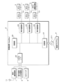
- FIG. 1 is a schematic diagram showing the configuration of an in-vehicle update system S according to Embodiment 1.
- FIG. 2 is a block diagram showing the configuration of the in-vehicle device 2 and the like.
- the in-vehicle update system S includes an in-vehicle communication device 1 and an in-vehicle device 2 mounted in a vehicle C, and a package (update program, operation check scenario) acquired from a program providing device S1 connected via an outside network N, It is transmitted to an in-vehicle ECU 3 (Electronic Control Unit/in-vehicle control device) installed in the vehicle C.
- ECU 3 Electric Control Unit/in-vehicle control device
- the program providing device S1 is a computer such as a server connected to an external network N such as the Internet or a public network, and includes a storage unit S11 such as a RAM (Random Access Memory), a ROM (Read Only Memory), or a hard disk. It is equipped and corresponds to an external server outside the vehicle.
- a program or data for controlling the in-vehicle ECU 3 created by the manufacturer of the in-vehicle ECU 3 or the like is stored in the storage unit S11.
- the program or data is transmitted to the vehicle C as an update program and used to update the program or data of the in-vehicle ECU 3 mounted on the vehicle C, as will be described later.
- the program providing apparatus S1 (external server) configured in this way is also called an OTA (Over The Air) server.
- the in-vehicle ECU 3 installed in the vehicle acquires the update program transmitted by wireless communication from the program providing device S1, and applies the update program as a program to execute, thereby updating the program executed by the own ECU (repro). can do.
- the program will be described as including program code including control syntax and the like for the in-vehicle ECU 3 to perform processing, and an external file in which data referred to when executing the program code is described.
- the external file containing the program code and data is transmitted from the program providing apparatus S1 as, for example, an encrypted archive file.
- the program providing device S1 When transmitting an update program, the program providing device S1 generates a package including the update program, and transmits the generated package to the vehicle C.
- the package includes, for example, package information (campaign information) that is information on program update, information on the in-vehicle ECU to be updated (target information), an update program applied to the in-vehicle ECU to be updated, and the update program that is installed in the vehicle.
- package information that is information on program update
- information on the in-vehicle ECU to be updated target information
- an update program applied to the in-vehicle ECU to be updated includes, for example, package information (campaign information) that is information on program update, information on the in-vehicle ECU to be updated (target information), an update program applied to the in-vehicle ECU to be updated, and the update program that is installed in the vehicle.
- the vehicle C is equipped with an external communication device 1, an in-vehicle device 2, a display device 5, and a plurality of in-vehicle ECUs 3 for controlling various in-vehicle devices.
- the external communication device 1 and the in-vehicle device 2 are communicably connected by a harness such as a serial cable.
- the in-vehicle device 2 and the in-vehicle ECU 3 are communicably connected by an in-vehicle LAN 4 compatible with a communication protocol such as CAN (Control Area Network/registered trademark) or Ethernet (registered trademark).
- the vehicle-external communication device 1 includes a vehicle-external communication unit (not shown) and an input/output I/F (not shown) (interface) for communicating with the in-vehicle device 2 .
- the external communication unit is a communication device for wireless communication using a mobile communication protocol such as 3G, LTE, 4G, 5G, WiFi, etc., and a program providing device via an antenna 11 connected to the external communication unit. Sends and receives data to and from S1. Communication between the external communication device 1 and the program providing device S1 is performed via a public network or an external network such as the Internet.
- the input/output I/F of the vehicle-external communication device 1 is a communication interface for serial communication with the vehicle-mounted device 2, for example.
- the external communication device 1 and the in-vehicle device 2 communicate with each other via a harness such as a serial cable connected between the input/output I/Fs.
- the vehicle-external communication device 1 is separate from the vehicle-mounted device 2, and these devices are communicably connected via an input/output I/F or the like, but the present invention is not limited to this.
- the external communication device 1 may be built in the in-vehicle device 2 as one component of the in-vehicle device 2 .
- the in-vehicle device 2 includes a control unit 20, a storage unit 21, and an in-vehicle communication unit 23.
- the in-vehicle device 2 acquires from the in-vehicle communication device 1 the update program (package) that the in-vehicle communication device 1 has received from the program providing device S1 by wireless communication, and transmits the update program via the in-vehicle LAN 4 to a predetermined in-vehicle ECU 3 (update It is configured to transmit to the target in-vehicle ECU 3). That is, the in-vehicle device 2 functions as an OTA master that controls program update in the in-vehicle ECU 3 to be updated.
- the in-vehicle device 2 controls a plurality of system buses (segments) such as a control system in-vehicle ECU 3, a safety system in-vehicle ECU 3, and a body system in-vehicle ECU 3. It is a gateway (in-vehicle relay device) that relays communication between That is, the in-vehicle device 2 functions as a CAN gateway in relaying the CAN protocol, and functions as a layer 2 switch or a layer 3 switch in relaying the TCP/IP protocol.
- system buses such as a control system in-vehicle ECU 3, a safety system in-vehicle ECU 3, and a body system in-vehicle ECU 3.
- the in-vehicle device 2 also serves as a power distribution device that distributes and relays power output from a power supply device such as a secondary battery, and supplies power to in-vehicle devices such as actuators connected to the device itself. It may be a functioning PLB (Power Lan Box). Alternatively, the in-vehicle device 2 may be configured as a functional part of a body ECU that controls the vehicle C as a whole. Alternatively, the in-vehicle device 2 may be an integrated ECU configured by a central control device such as a vehicle computer, for example, and performing overall control of the vehicle.
- a power supply device such as a secondary battery
- PLB Power Lan Box
- the in-vehicle device 2 may be configured as a functional part of a body ECU that controls the vehicle C as a whole.
- the in-vehicle device 2 may be an integrated ECU configured by a central control device such as a vehicle computer, for example, and performing overall control of the vehicle.
- the control unit 20 is configured by a CPU (Central Processing Unit) or MPU (Micro Processing Unit), etc. By reading and executing a control program P (program product) and data stored in advance in the storage unit 21, Various control processing and arithmetic processing are performed.
- a control program P program product
- the storage unit 21 is composed of a volatile memory element such as RAM (Random Access Memory) or a non-volatile memory element such as ROM (Read Only Memory), EEPROM (Electrically Erasable Programmable ROM) or flash memory, A control program and data to be referred to during processing are stored in advance.
- the control program P (program product) stored in the storage unit 21 may be the control program P (program product) read from the recording medium 211 readable by the in-vehicle device 2 .
- the control program may be downloaded from an external computer (not shown) connected to a communication network (not shown) and stored in the storage unit 21 .
- the storage unit 21 stores vehicle configuration information in which the configuration information of each in-vehicle ECU installed in the vehicle is aggregated.
- vehicle configuration information includes, for example, the production number (serial number) of each in-vehicle ECU, the ECU part number (model number), the software part number, the current version of the program, the old version, the number of operation surfaces, the operation surface, MAC (Media Access Control) Address, IP address, last update completion date, repro status and VIN (vehicle identification number).
- the storage unit 21 stores relay route information (routing table) used for performing relay processing for communication between the in-vehicle ECUs 3 or communication between the in-vehicle ECUs 3 and the external server 100 .
- the format of the relay route information is determined based on the communication protocol.
- the relay route information for CAN includes the message identifier (CAN-ID) included in the CAN message and the relay destination (I / O port number of the CAN communication unit 232) associated with the CAN-ID. including.
- the TCP/IP relay route information includes the destination address (MAC address or IP address) included in the IP packet and the relay destination associated with the destination address (Ethernet communication unit 231 physical port number).
- the relay route information (routing table) may be included in the vehicle configuration information.
- the storage unit 21 further stores relay logs collected when performing relay processing of communication between a plurality of in-vehicle ECUs.
- the relay log includes, for example, data such as header information (source address, destination address, message ID, etc.), payload information, transmission/reception frequency or cycle of the Ether frame or CAN message to be relayed.
- the data may be associated with a time stamp indicating communication history.
- the relay log can be used as data indicating the communication state and communication history in the actual operating environment (actual vehicle environment) of the vehicle in which the in-vehicle device is mounted.
- the input/output I/F 22 is, like the input/output I/F of the external communication device 1, a communication interface for serial communication, for example.
- the in-vehicle device 2 is communicably connected to the external communication device 1, the display device 5 (HMI device), and the IG switch 6 for starting and stopping the vehicle C via the input/output I/F 22 .
- the in-vehicle communication unit 23 is an input/output interface (CAN transceiver, Ethernet PHY unit) using a communication protocol such as CAN (Control Area Network), CAN-FD (CAN with Flexible Data Rate), or Ethernet (registered trademark). It functions as a communication unit for communication between the in-vehicle device 2 and the in-vehicle ECU 3 .
- a plurality of in-vehicle communication units 23 are provided, and each communication line 41 (Ethernet cable, CAN bus) constituting the in-vehicle network 4, that is, each bus is connected to each in-vehicle communication unit 23 .
- the in-vehicle network 4 is divided into a plurality of buses (segments), and the in-vehicle ECU 3 is connected to each segment according to the function of the in-vehicle ECU 3. good.
- the control unit 20 of the in-vehicle device 2 communicates with the in-vehicle ECU 3 connected to the in-vehicle network 4 via the in-vehicle communication unit 23 .
- the vehicle-mounted ECU 3 includes a control unit (not shown), a storage unit (not shown), and an in-vehicle communication unit (not shown), similar to the vehicle-mounted device 2 .
- the storage unit is composed of volatile memory elements such as RAM (Random Access Memory) or non-volatile memory elements such as ROM (Read Only Memory), EEPROM (Electrically Erasable Programmable ROM), or flash memory.
- RAM Random Access Memory
- ROM Read Only Memory
- EEPROM Electrical Erasable Programmable ROM
- flash memory flash memory
- a program or data for the ECU 3 is stored. This program or data is an object to be updated by an update program transmitted from the program providing device and relayed by the in-vehicle device 2 .
- An in-vehicle communication unit of the in-vehicle ECU 3 is configured by, for example, a CAN transceiver or an Ethernet PHY unit, like the in-vehicle device 2, and communicates with the in-vehicle device 2 via the in-vehicle communication unit.
- the display device 5 is, for example, an HMI (Human Machine Interface) device such as a car navigation display.
- the display device 5 is communicably connected to the input/output I/F 22 of the in-vehicle device 2 by a harness such as a serial cable. Data or information output from the control unit 20 of the in-vehicle device 2 via the input/output I/F 22 is displayed on the display device 5 .
- HMI Human Machine Interface
- FIG. 3 is an explanatory diagram illustrating the flow (sequence) of processing by the in-vehicle device 2 and the in-vehicle ECU 3 for updating.
- each process of the program providing device S1 (OTA server), the in-vehicle device 2 (OTA master), and the in-vehicle ECU 3 to be updated (target ECU) A sequence is explained.
- the in-vehicle device 2 outputs (transmits) the vehicle configuration information of the vehicle C (own vehicle) to the program providing device S1 (S01).
- the in-vehicle device 2 routinely acquires program information, type information, etc. applied to the in-vehicle ECU 3 from each in-vehicle ECU 3, and generates and stores vehicle configuration information by aggregating these information.
- the in-vehicle device 2 may include VIN (Vehicle Identification Number) in the vehicle configuration information.
- the program providing device S1 generates a package including the update program and the operation confirmation scenario (S02).
- the program providing device S1 generates a package based on the vehicle configuration information acquired from the in-vehicle device 2.
- FIG. The package contains package information (campaign information) that is information on program update, information on the in-vehicle ECU 3 to be updated (target information), an update program applied to the in-vehicle ECU 3 to be updated, and the update program installed in the vehicle.
- An operation confirmation scenario for confirming the operation when applied to the ECU 3 is included.
- execution procedures such as processing sequences, scripts, commands, etc. for operation confirmation performed by the in-vehicle device 2 for the in-vehicle ECU 3 to be updated are listed.
- the operation confirmation scenario further includes a processing sequence for operation confirmation performed by the in-vehicle ECU 3 to be updated, and judgment information for verifying (success/failure judgment) the result of operation confirmation by the in-vehicle device 2 and the in-vehicle ECU 3 to be updated.
- the program providing device S1 can generate an operation confirmation scenario suitable for the actual environment of the vehicle C in which the in-vehicle device 2 is mounted.
- the program providing device S1 outputs (transmits) the generated package to the in-vehicle device 2 (S03).
- the in-vehicle device 2 stores the package acquired (received) from the program providing device S1 in the storage unit S11 (S04).
- the in-vehicle device 2 may shift (transition) from the normal mode (state during normal operation of the vehicle C) to the update mode by acquiring the package from the program providing device S1.
- the in-vehicle device 2 outputs (transmits) the update program and the operation check scenario included in the package to the in-vehicle ECU 3 to be updated (S05).
- the in-vehicle ECU 3 to be updated stores the update program and the operation confirmation scenario obtained (received) from the in-vehicle device 2 in the storage unit (S06).
- the in-vehicle ECU 3 to be updated receives the update program and the operation confirmation scenario from the in-vehicle device 2, thereby shifting (transitioning) to the update mode.
- the storage unit of the in-vehicle ECU 3 to be updated stores a first storage area that stores the currently applied program (current version program) and a previously applied program (old version program). and a second storage area.
- the in-vehicle ECU 3 to be updated stores the update program and the operation check scenario acquired from the in-vehicle device 2 in the second storage area, thereby performing the update without overwriting the current version of the program stored in the first storage area. It may be one that saves (stores) a program or the like.
- the in-vehicle ECU 3 to be updated can reliably perform rollback processing to return to the old version of the program by providing a dual storage unit having a first storage area and a second storage area.
- the in-vehicle device 2 issues an activation request (instruction to apply the update program) to the in-vehicle ECU 3 to be updated (S07).
- the in-vehicle device 2 transmits a control signal (activation request signal) to the in-vehicle ECU 3 to be updated, for example, to make an activation request (instruction to apply the update program).
- the activation request is triggered by turning off the IG switch 6, the activation request is not limited to this. may be
- the in-vehicle ECU 3 to be updated switches from the currently applied program to the update program in response to the activation request from the in-vehicle device 2 (S08).
- the in-vehicle ECU 3 to be updated outputs (transmits) information (activation result) indicating switching to the update program to the in-vehicle device 2 (S09).
- the in-vehicle ECU 3 to be updated has, as described above, a two-sided storage unit having a first storage area and a second storage area, and validating (activating) the second storage area in which the update program is stored. switch to the update program.
- the in-vehicle device 2 requests the in-vehicle ECU 3 to be updated to switch to the operation check mode according to the operation check scenario stored in the storage unit 21 (S10).
- the in-vehicle device 2 requests the transition to the operation check mode by, for example, transmitting a control signal (an operation check mode transition signal) to the in-vehicle ECU 3 to be updated.
- the in-vehicle ECU 3 to be updated shifts (transitions) to the operation confirmation mode in response to a request from the in-vehicle device 2 to shift to the operation confirmation mode (S11).
- the in-vehicle ECU 3 to be updated which has shifted to the operation check mode, executes the update program based on the operation check scenario.
- the operation confirmation scenario includes a sequence relating to self-diagnosis processing (individual diagnosis) performed within the own ECU (inside the in-vehicle ECU 3 to be updated).
- the in-vehicle ECU 3 to be updated, which has shifted to the operation check mode performs self-diagnosis processing (individual diagnosis) performed within its own ECU based on the operation check scenario.
- the in-vehicle device 2 outputs (transmits) operation check data to the update target in-vehicle ECU 3 based on the operation check scenario (S12).
- the in-vehicle device 2 outputs the operation confirmation data to the in-vehicle ECU 3 to be updated
- the in-vehicle device 2 replaces another in-vehicle ECU 3 with which the in-vehicle ECU 3 to be updated normally communicates.
- the in-vehicle device 2 substitutes for another in-vehicle ECU 3
- the in-vehicle device 2 may transmit an Ethernet frame having the IP address of the other in-vehicle ECU 3 as a source address.
- the in-vehicle device 2 may transmit a CAN message including the CAN-ID used by the other in-vehicle ECU 3 .
- the in-vehicle ECU 3 to be updated outputs (transmits) response data to the in-vehicle device 2 according to the operation confirmation data transmitted from the in-vehicle device 2 substituting for the other in-vehicle ECU 3 (S13).
- a processing sequence of data transmission/reception between the in-vehicle device 2 substituting for another in-vehicle ECU 3 and the update target in-vehicle ECU 3 is performed based on an operation check scenario.
- the control over the sensor or actuator connected to the in-vehicle ECU 3 to be updated may be omitted or disabled.
- the in-vehicle device 2 and the in-vehicle ECU 3 to be updated may store response values in the processing sequence by transmission and reception of these data, or measured values (actual values) such as communication traffic volume, and store them as operation check results. .
- the in-vehicle ECU 3 to be updated outputs (sends) to the in-vehicle device 2 the result of the unit diagnosis and the result of operation confirmation by data transmission/reception with the in-vehicle device 2 (S14).
- the operation check scenario includes unit diagnosis judgment information for judging the result of the unit diagnosis.
- the unit diagnostic determination information is expected values such as a process list, CPU usage, and memory usage generated in the in-vehicle ECU 3 to be updated when the update program is executed (activated).
- the in-vehicle ECU 3 to be updated judges the result of the single diagnosis by comparing various actual measurement values in the result of the single diagnosis with various expected values in the determination information for single diagnosis. If the actual measurement value in the result of the unit diagnosis matches the expected value in the determination information for unit diagnosis, the in-vehicle ECU 3 to be updated determines that the result of the unit diagnosis performed based on the operation check scenario is positive (program update is successful). ). If the measured value in the result of the unit diagnosis does not match the expected value in the determination information for unit diagnosis, the in-vehicle ECU 3 to be updated determines that the result of the unit diagnosis performed based on the operation confirmation scenario is negative (program update failed). ).
- the in-vehicle device 2 stores, in the storage unit 21, the result of the operation check by data transmission/reception with the in-vehicle ECU 3 to be updated (S15).
- the in-vehicle device 2 stores in the storage unit 21 the result of the operation check output from the in-vehicle ECU 3 to be updated. Furthermore, the in-vehicle device 2 also stores in the storage unit 21 the result of the operation confirmation verified by the own device.
- the in-vehicle device 2 compares the determination information included in the operation check scenario with various values (measured values, actual values) included in the result of the operation check. , whether or not the update of the program in the in-vehicle ECU 3 to be updated has succeeded (success or failure) is determined (S16).
- the determination information includes, for example, an expected value regarding response data from the update target vehicle ECU 3 to the operation confirmation data transmitted from the vehicle device 2 substituting for another vehicle ECU 3 to the update target vehicle ECU 3. .
- the expected values for the response data are, for example, presence/absence of response data, type (header information), data length, payload information, and return response value of response data.
- the in-vehicle device 2 In data transmission/reception with the in-vehicle ECU 3 to be updated, the in-vehicle device 2 includes the presence or absence of response data from the in-vehicle ECU 3 to be updated, measured values such as data length or reply response value, and determination information (response The result of the operation check is verified by comparing with the expected value of data). If the response data from the in-vehicle ECU 3 to be updated matches the determination information, that is, the expected value defined in the operation check scenario (expected value regarding the response data), the in-vehicle device 2 performs the operation check based on the operation check scenario. It is determined that the result of the operation check is affirmative (program update is successful).
- the in-vehicle device 2 If the response data from the in-vehicle ECU 3 to be updated does not match the determination information, that is, the expected value defined in the operation check scenario (expected value related to the response data), the in-vehicle device 2 performs the operation check based on the operation check scenario. It is determined that the result of the operation check is negative (program update failed).
- the in-vehicle device 2 determines whether or not the update of the program in the in-vehicle ECU 3 to be updated is successful based on the result of the single diagnosis acquired from the in-vehicle ECU 3 to be updated and the result of the operation check by data transmission/reception with the in-vehicle device 2. (success or failure). That is, the in-vehicle device 2 receives the result of operation check related to the transmission and reception of the operation check data from its own device side, the result of the operation check related to the transmission and reception of the operation check data from the in-vehicle ECU 3 side, and the single diagnosis in the in-vehicle ECU 3.
- the success or failure determination of the update of the program in vehicle-mounted ECU3 of update object is performed.
- the in-vehicle device 2 determines that the update of the program in the in-vehicle ECU 3 to be updated has succeeded.
- the in-vehicle device 2 requests the in-vehicle ECU 3 to be updated to switch to the normal mode (S17).
- the in-vehicle ECU 3 to be updated shifts (transitions) to the normal mode in response to the request from the in-vehicle device 2 to shift to the normal mode (S18).
- the in-vehicle ECU 3 to be updated receives the request to shift to the normal mode from the in-vehicle device 2, the update of the program in the in-vehicle ECU 3 to be updated is completed, and the in-vehicle ECU 3 performs the operation when the vehicle C travels. It shifts (transitions) to a state (normal mode) in which control is performed in a normal manner.
- the in-vehicle device 2 determines that the update of the program in the in-vehicle ECU 3 to be updated has failed. When it is determined that the update of the program has failed, the in-vehicle device 2 may request the in-vehicle ECU 3 to be updated to perform rollback processing. The in-vehicle device 2 may decide whether to take either the rollback process or the transition to the degeneracy mode based on these three confirmation results. The in-vehicle device 2 may output, for example, the display device 5 to notify the operator of the vehicle C that the update of the program has failed.
- the in-vehicle device 2 outputs (transmits) the result of the operation check based on the operation check scenario to the program providing device S1 (S19).
- the program providing device S1 that has obtained the result of the operation check output from the in-vehicle device 2 stores the result in the storage unit S11 of its own device. Accordingly, it is possible to harmonize (synchronize) the information regarding the program update based on the package between the in-vehicle device 2 and the program providing device S1.
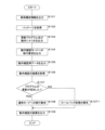
- FIG. 4 is a flowchart illustrating the processing of the control unit 20 of the in-vehicle device 2.
- the control unit 20 of the in-vehicle device 2 routinely performs the following processing, for example, when the vehicle C is in an activated state (the IG switch 6 is on).
- the control unit 20 of the in-vehicle device 2 outputs (transmits) vehicle configuration information of the vehicle C (own vehicle) to the program providing device S1 (S101).
- the output of the vehicle configuration information to the program providing device S1 by the control unit 20 of the in-vehicle device 2 is not limited to when performing the program update processing for the in-vehicle ECU 3, and the output of the vehicle configuration information is performed constantly. There may be. That is, the control unit 20 of the in-vehicle device 2 steadily or periodically acquires program information and model information applied to the in-vehicle ECUs 3 from all the in-vehicle ECUs 3 mounted in the vehicle C (own vehicle). , and stores the acquired and aggregated information as vehicle configuration information.
- the control unit 20 of the in-vehicle device 2 may regularly or periodically provide the program providing device S1 with the vehicle configuration information including the VIN.
- the program providing device S1 identifies the target vehicle C based on the vehicle configuration information including the VIN, and creates a package corresponding to the identified vehicle C.
- the package created by the program providing device S1 includes package information (campaign information) that is information on program update, information on the in-vehicle ECU 3 to be updated (target information), an update program (update data), and an operation check scenario. .
- the control unit 20 of the in-vehicle device 2 acquires the package containing the update program and the operation check scenario from the program providing device S1 (S102).
- the control unit 20 of the in-vehicle device 2 communicates with the program providing device S1 via the external communication device 1 and acquires the package from the program providing device S1.
- the control unit 20 of the in-vehicle device 2 stores the acquired package in the storage unit 21 .
- the control unit 20 of the in-vehicle device 2 outputs the update program and the operation confirmation scenario to the in-vehicle ECU 3 to be updated (S103).
- the operation check scenario is shared by the in-vehicle device 2 and the in-vehicle ECU 3 to be updated. That is, the in-vehicle device 2 and the in-vehicle ECU 3 to be updated can perform the operation check process based on the same operation check scenario.
- the control unit 20 of the in-vehicle device 2 outputs an update program and an operation check scenario to the in-vehicle ECU 3 to be updated, and outputs an activation request indicating that the update program is to be applied to the in-vehicle ECU 3. There may be.
- the control unit 20 of the in-vehicle device 2 outputs a request to shift to the operation check mode to the in-vehicle ECU 3 to be updated (S104).
- the in-vehicle ECU 3 to be updated that acquires (receives) the request to shift to the operation check mode from the in-vehicle device 2 starts executing the operation check based on the operation check scenario when applying the update program.
- the control unit 20 of the in-vehicle device 2 outputs operation confirmation data to the in-vehicle ECU 3 to be updated based on the operation confirmation scenario (S105).
- the vehicle-mounted ECU 3 to be updated performs data communication with other vehicle-mounted ECUs 3 instead of the vehicle-mounted device 2 .
- the in-vehicle device 2 replaces the other in-vehicle ECU 3 so as to simulate the operation mode of the other in-vehicle ECU 3 .
- in-vehicle ECU3 of update object of operation check mode performs a series of processing sequences including transmission and reception of data between in-vehicle devices 2 which replaced other in-vehicle ECU3.
- the controller 20 of the in-vehicle device 2 outputs operation confirmation data to the update target vehicle ECU 3, and the update target vehicle ECU 3 similarly outputs response data based on the operation confirmation scenario. That is, the control unit 20 of the in-vehicle device 2 and the in-vehicle ECU 3 to be updated start transmitting and receiving data in accordance with the actual vehicle environment according to the same operation confirmation scenario.
- the control unit 20 of the in-vehicle device 2 acquires the result of operation confirmation according to the operation confirmation scenario (S106).
- the in-vehicle ECU 3 to be updated outputs to the in-vehicle device 2 the result of the unit diagnosis and the result of the operation check regarding the transmission and reception of the data for operation check from the own ECU side.
- the control unit 20 of the in-vehicle device 2 acquires these results from the in-vehicle ECU 3 to be updated. Furthermore, the control unit 20 of the in-vehicle device 2 acquires the result of the operation check regarding the transmission and reception of the operation check data from the own device side.
- various measured values are stored in the storage unit 21 of the in-vehicle device 2 in the operation check performed based on the operation check scenario.
- the control unit 20 of the in-vehicle device 2 acquires the result of the operation check regarding the transmission and reception of the operation check data from the own device by referring to the storage unit 21 of the own device. That is, the control unit 20 of the in-vehicle device 2 acquires these three operation confirmation results.
- the control unit 20 of the in-vehicle device 2 determines whether or not the update of the program in the in-vehicle ECU 3 to be updated has succeeded (S107).
- the operation confirmation scenario includes judgment information for judging the result of operation confirmation.
- the control unit 20 of the in-vehicle device 2 determines whether or not the program has been successfully updated by comparing various actual measurement values obtained as a result of the operation check with the expected value included in the determination information. For example, when all measured values are within the range of expected values, the control unit 20 of the in-vehicle device 2 determines that the program has been successfully updated.
- the control unit 20 of the in-vehicle device 2 determines that the update of the program has failed if, for example, all the measured values do not fall within the range of the expected values.
- the control unit 20 of the in-vehicle device 2 requests the in-vehicle ECU 3 to be updated to switch to the normal mode (S108).
- the control unit 20 of the in-vehicle device 2 for example, outputs a control signal (normal mode transition signal) to the in-vehicle ECU 3 to be updated, thereby requesting the transition to the normal mode.
- the in-vehicle ECU 3 to be updated that receives the request to shift to the normal mode shifts to the normal mode.
- the control unit 20 of the in-vehicle device 2 requests the in-vehicle ECU 3 to be updated to perform rollback processing (S1071 ).
- the control unit 20 of the in-vehicle device 2 requests rollback processing by, for example, outputting a control signal (rollback signal) to the in-vehicle ECU 3 to be updated.
- the control unit 20 of the in-vehicle device 2 may decide whether to request the rollback process or shift to the degeneracy mode according to the mode of the result of the operation check. good.
- the control unit 20 of the in-vehicle device 2 outputs (transmits) the result of the operation check based on the operation check scenario to the program providing device S1 (S109).
- the control unit 20 of the in-vehicle device 2 outputs (transmits) the result of the operation check based on the operation check scenario to the program providing device S1 via the external communication device 1 .
- the control unit 20 of the in-vehicle device 2 may output the result of operation confirmation based on the operation confirmation scenario to the display device 5 and notify the operator of the vehicle C or the like of the result.
- the in-vehicle ECU 3 to be updated and the in-vehicle device 2 perform operation check of the in-vehicle ECU 3 to which the update program is applied (in-vehicle ECU 3 to be updated) based on the same operation check scenario. It is possible to efficiently check the operation of the vehicle C in which the ECU 3 and the in-vehicle device 2 are mounted under the actual environment.
- the in-vehicle device 2 substitutes for another in-vehicle ECU 3 other than the in-vehicle ECU 3 to be updated. It becomes possible to perform transmission, and it is possible to efficiently check the operation of the vehicle C in accordance with the actual environment.
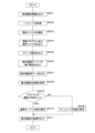
- FIG. 5 is a flowchart illustrating processing of the control unit 20 of the in-vehicle device 2 according to the second embodiment.
- the control unit 20 of the in-vehicle device 2 outputs (transmits) vehicle configuration information of the vehicle C (own vehicle) to the program providing device S1 (S201).
- the control unit 20 of the in-vehicle device 2 acquires the package including the update program and the operation check scenario from the program providing device S1 (S202).
- the control unit 20 of the in-vehicle device 2 performs the processes of S201 and S202 in the same manner as the processes S101 and S102 of the first embodiment.
- the control unit 20 of the in-vehicle device 2 complements the operation check scenario using the relay log collected when the communication relay processing was performed between the multiple in-vehicle ECUs 3 (S203).
- the in-vehicle device 2 includes a plurality of in-vehicle communication units 23 and functions as an in-vehicle relay device that relays communication between the in-vehicle ECUs 3 connected to these in-vehicle communication units 23 .
- the control unit 20 of the in-vehicle device 2 stores a relay log in the storage unit 21 based on the relayed data (Etherframe, CAN message).
- the relay log includes, for example, header information (source address, destination address, message ID, etc.), payload information, transmission/reception frequency or cycle, etc. of the Ethernet frame or CAN message to be relayed. is data indicating the communication state in the actual operating environment (actual vehicle environment) of the vehicle C in which the is mounted.
- the control unit 20 of the in-vehicle device 2 uses the relay log to add or modify the sequence related to data transmission/reception included in the operation check scenario, so that the operation check scenario generated by the program providing device S1 is further processed in the actual vehicle environment.
- Complement according to The control unit 20 of the in-vehicle device 2 uses the complemented operation confirmation scenario to perform subsequent processing. That is, in subsequent processes, the operation check scenario used by the control unit 20 of the in-vehicle device 2 and the in-vehicle ECU 3 to be updated is the operation check scenario complemented using the relay log.
- the control unit 20 of the in-vehicle device 2 outputs the update program and the operation confirmation scenario to the in-vehicle ECU 3 to be updated (S204).
- the control unit 20 of the in-vehicle device 2 performs the process of S204 in the same manner as the process S103 of the first embodiment.
- the control unit 20 of the in-vehicle device 2 outputs a sleep signal to the other in-vehicle ECUs 3 other than the in-vehicle ECU 3 to be updated (S205).
- the control unit 20 of the in-vehicle device 2 can grasp all the in-vehicle ECUs 3 installed in the vehicle C (own vehicle) by referring to, for example, the vehicle configuration information or the routing table used for relay processing. .
- the control unit 20 of the in-vehicle device 2 specifies other in-vehicle ECUs 3 other than the in-vehicle ECU 3 to be updated among all the in-vehicle ECUs 3 installed in the vehicle C (own vehicle).
- the control unit 20 of the in-vehicle device 2 outputs (transmits) a sleep signal for transitioning to the sleep mode to the specified other in-vehicle ECU 3 .
- Other in-vehicle ECU3 which received the sleep signal stops processing, such as transmission and reception of data, by changing to sleep mode. Thereby, it is possible to perform the process of updating the program to the in-vehicle ECU 3 to be updated while preventing the other in-vehicle ECU 3 other than the in-vehicle ECU 3 to be updated from being affected.
- the control unit 20 of the in-vehicle device 2 outputs a sleep signal
- the present invention is not limited to this. Communication of other in-vehicle ECU3 may be restricted.
- the control unit 20 of the in-vehicle device 2 outputs a request to shift to the operation check mode to the in-vehicle ECU 3 to be updated (S206).
- the control unit 20 of the in-vehicle device 2 outputs operation confirmation data to the in-vehicle ECU 3 to be updated based on the operation confirmation scenario (S207).
- the control unit 20 of the in-vehicle device 2 acquires the result of operation confirmation based on the operation confirmation scenario (S208).
- the control unit 20 of the in-vehicle device 2 determines whether or not the update of the program in the in-vehicle ECU 3 to be updated has succeeded (S209).
- the control unit 20 of the in-vehicle device 2 requests the in-vehicle ECU 3 to be updated to switch to the normal mode (S210).
- the update of the program fails (S209: NO), that is, when the update of the program fails, the control unit 20 of the in-vehicle device 2 requests the in-vehicle ECU 3 to be updated to perform rollback processing (S2091 ).
- the control unit 20 of the in-vehicle device 2 outputs (transmits) the result of the operation check based on the operation check scenario to the program providing device S1 (S211).
- the control unit 20 of the in-vehicle device 2 performs the processing from S206 to S211 in the same manner as the processing from S104 to S109 of the first embodiment.
- the in-vehicle device 2 supplements the operation confirmation scenario acquired from the external server by adding, etc., using the relay log at the time of performing the relay processing.
- the suitability of verification scenarios can be improved.
- the operation check scenario complemented operation check scenario
- the accuracy of the operation check when the update program is applied to the in-vehicle ECU 3 to be updated is improved. can be improved.
Abstract
This in-vehicle device is an in-vehicle updating device which acquires an updating program transmitted from an external server outside a vehicle and performs a process for updating a program of an in-vehicle ECU mounted to the vehicle, and the in-vehicle updating device comprises a control unit that performs a process regarding the updating program. When acquiring the updating program, the control unit acquires, from the external server, an operation confirmation scenario for confirming operation of a to-be-updated in-vehicle ECU, outputs the acquired updating program and operation confirmation scenario to the to-be-updated in-vehicle ECU, and performs, on the basis of the operation confirmation scenario, a process regarding the operation confirmation for the to-be-updated in-vehicle ECU.
Description
本開示は、車載装置、プログラム及び、プログラムの更新方法に関する。
本出願は、2021年10月12日出願の日本出願第2021-167466号に基づく優先権を主張し、前記日本出願に記載された全ての記載内容を援用するものである。 The present disclosure relates to an in-vehicle device, a program, and a program update method.
This application claims priority based on Japanese application No. 2021-167466 filed on October 12, 2021, and incorporates all the descriptions described in the Japanese application.
車両には、エンジン制御等の駆動制御系、エアコン制御等のボディ系等の車載機器を制御するためのECU(Electronic Control Unit)が搭載されている。ECUは、MPU等の演算処理部、RAM等の書き換え可能な不揮発性の記憶部、及び他のECUと通信するための通信部を含み、記憶部に記憶した制御プログラムを読み込んで実行することにより、車載機器の制御を行う。更に車両には、無線通信の機能を備えた通信機が実装されており、通信機を介して、車外のネットワークに接続されているプログラム提供装置と通信し、当該プログラム提供装置からECUの制御プログラムをダウンロード(受信)し、当該ECUの制御プログラムを更新することができる(例えば特許文献1参照)。
The vehicle is equipped with an ECU (Electronic Control Unit) that controls onboard equipment such as drive control systems such as engine control and body systems such as air conditioner control. The ECU includes an arithmetic processing unit such as an MPU, a rewritable non-volatile storage unit such as a RAM, and a communication unit for communicating with other ECUs. , controls the on-board equipment. Furthermore, the vehicle is equipped with a communication device having a wireless communication function. can be downloaded (received) to update the control program of the ECU (see, for example, Patent Document 1).
本開示の一態様に係る車載装置は、車外の外部サーバから送信される更新プログラムを取得し、車両に搭載される車載ECUのプログラムを更新するための処理を行う車載更新装置であって、前記更新プログラムに関する処理を行う制御部を備え、前記制御部は、前記更新プログラムを取得する際、更新対象の車載ECUに対する動作確認を行うための動作確認シナリオを前記外部サーバから取得し、取得した前記更新プログラム及び前記動作確認シナリオを前記更新対象の車載ECUに出力し、前記動作確認シナリオに基づき、前記更新対象の車載ECUに対する動作確認に関する処理を行う。
An in-vehicle device according to an aspect of the present disclosure is an in-vehicle update device that acquires an update program transmitted from an external server outside the vehicle and performs processing for updating a program of an in-vehicle ECU installed in the vehicle, A control unit that performs processing related to an update program, wherein the control unit acquires from the external server an operation check scenario for performing an operation check on an in-vehicle ECU to be updated when acquiring the update program, and The update program and the operation check scenario are output to the update target in-vehicle ECU, and processing regarding operation check for the update target in-vehicle ECU is performed based on the operation check scenario.
[本開示が解決しようとする課題]
特許文献1の通信機(中継機)は、ダウンロードした制御プログラムを更新対象のECUに適用するにあたり、当該更新対象のECUに制御プログラムを適用した際の動作確認を行う点が、考慮されていないという問題点がある。 [Problems to be Solved by the Present Disclosure]
The communication device (relay device) of Patent Document 1 does not take into consideration the fact that when a downloaded control program is applied to an ECU to be updated, an operation check is performed when the control program is applied to the ECU to be updated. There is a problem.
本開示の目的は、車載ECUのプログラムを更新する処理を行うにあたり、当該プログラムが適用された車載ECUに対する動作確認を効率的に行うことができる車載装置等を提供する。
The purpose of the present disclosure is to provide an in-vehicle device or the like that can efficiently check the operation of an in-vehicle ECU to which the program is applied when performing processing to update the program of the in-vehicle ECU.
[本開示の効果]
本開示の一態様によれば、車載ECUのプログラムを更新する処理を行うにあたり、当該プログラムが適用された車載ECUに対する動作確認を効率的に行う車載装置等を提供することができる。 [Effect of the present disclosure]
According to one aspect of the present disclosure, it is possible to provide an in-vehicle device or the like that efficiently checks the operation of an in-vehicle ECU to which the program is applied when performing processing for updating a program in the in-vehicle ECU.
[本開示の実施形態の説明]
最初に本開示の実施態様を列挙して説明する。また、以下に記載する実施形態の少なくとも一部を任意に組み合わせてもよい。 [Description of Embodiments of the Present Disclosure]
First, embodiments of the present disclosure are enumerated and described. Moreover, at least part of the embodiments described below may be combined arbitrarily.
最初に本開示の実施態様を列挙して説明する。また、以下に記載する実施形態の少なくとも一部を任意に組み合わせてもよい。 [Description of Embodiments of the Present Disclosure]
First, embodiments of the present disclosure are enumerated and described. Moreover, at least part of the embodiments described below may be combined arbitrarily.
(1)本開示の一態様に係る車載装置は、車外の外部サーバから送信される更新プログラムを取得し、車両に搭載される車載ECUのプログラムを更新するための処理を行う車載更新装置であって、前記更新プログラムに関する処理を行う制御部を備え、前記制御部は、前記更新プログラムを取得する際、更新対象の車載ECUに対する動作確認を行うための動作確認シナリオを前記外部サーバから取得し、取得した前記更新プログラム及び前記動作確認シナリオを前記更新対象の車載ECUに出力し、前記動作確認シナリオに基づき、前記更新対象の車載ECUに対する動作確認に関する処理を行う。
(1) An in-vehicle device according to an aspect of the present disclosure is an in-vehicle update device that acquires an update program transmitted from an external server outside the vehicle and performs processing for updating a program of an in-vehicle ECU installed in the vehicle. a control unit that performs processing related to the update program, wherein the control unit acquires from the external server an operation check scenario for performing an operation check on an in-vehicle ECU to be updated when acquiring the update program; The acquired update program and the operation check scenario are output to the update target vehicle ECU, and based on the operation check scenario, the update target vehicle ECU is processed for operation check.
本態様にあたっては、車載装置(制御部)は、更新対象の車載ECUに対し更新プログラム及び動作確認シナリオを出力し、当該動作確認シナリオに基づき、更新対象の車載ECUに対する動作確認に関する処理を行う。当該動作確認シナリオには、更新対象の車載ECUに対し、車載装置が行う動作確認用の処理シーケンス、スクリプト、又はコマンド等の実行手順が列挙されている。車載装置から更新プログラム及び動作確認シナリオを取得した車載ECU(更新対象の車載ECU)は、取得した更新プログラムを適用した後、当該更新プログラムと併せて取得した動作確認シナリオに基づき、自ECUにおける動作確認に関する処理を行う。これにより、更新対象の車載ECU及び車載装置は、同じ動作確認シナリオに基づき、更新プログラムが適用された車載ECU(更新対象の車載ECU)の動作確認を行うものとなり、これら車載ECU及び車載装置が搭載される車両の実環境下での動作確認を効率的に行うことができる。
In this aspect, the in-vehicle device (control unit) outputs an update program and an operation confirmation scenario to the in-vehicle ECU to be updated, and performs processing related to operation confirmation of the in-vehicle ECU to be updated based on the operation confirmation scenario. In the operation confirmation scenario, execution procedures such as a processing sequence, a script, a command, or the like for operation confirmation performed by the in-vehicle device for the in-vehicle ECU to be updated are listed. An in-vehicle ECU that has acquired an update program and an operation check scenario from an in-vehicle device (an in-vehicle ECU to be updated) applies the acquired update program, and then performs operation in its own ECU based on the operation check scenario acquired together with the update program. Perform processing related to confirmation. As a result, the in-vehicle ECU and in-vehicle device to be updated will check the operation of the in-vehicle ECU to which the update program has been applied (in-vehicle ECU to be updated) based on the same operation check scenario. It is possible to efficiently check the operation under the actual environment of the vehicle in which it is mounted.
(2)本開示の一態様に係る車載装置は、前記制御部は、前記動作確認シナリオに基づき、前記更新対象の車載ECU以外の他の車載ECUを代替することにより、前記更新対象の車載ECUに対する動作確認に関する処理を行う。
(2) In an in-vehicle device according to an aspect of the present disclosure, the control unit replaces an in-vehicle ECU other than the in-vehicle ECU to be updated based on the operation confirmation scenario, thereby replacing the in-vehicle ECU to be updated. Perform processing related to operation confirmation for
本態様にあたっては、車載装置は、更新対象の車載ECU以外の他の車載ECUを代替することにより、更新対象の車載ECUに対する動作確認に関する処理を行うため、車両の実環境に則した動作確認を効率的に行うことができる。
In this aspect, the in-vehicle device performs processing related to the operation check for the in-vehicle ECU to be updated by substituting another in-vehicle ECU other than the in-vehicle ECU to be updated. can be done efficiently.
(3)本開示の一態様に係る車載装置は、前記動作確認シナリオは、前記他の車載ECUを代替する前記制御部が、前記更新対象の車載ECUに対しデータを送信する処理シーケンスと、前記更新プログラムが適用された前記更新対象の車載ECUが、前記制御部によって代替された前記他の車載ECUに対しデータを送信する処理シーケンスとを含む。
(3) In the in-vehicle device according to an aspect of the present disclosure, the operation confirmation scenario includes a processing sequence in which the control unit substituting for the other in-vehicle ECU transmits data to the update target in-vehicle ECU; and a processing sequence in which the update target in-vehicle ECU to which the update program is applied transmits data to the other in-vehicle ECU replaced by the control unit.
本態様にあたっては、動作確認シナリオは、他の車載ECUを代替した車載装置と、更新プログラムが適用された車載ECU(更新対象の車載ECU)とによるデータの送受信が定められた処理シーケンスを含むため、車両の実環境に則した動作確認を効率的に行うことができる。すなわち、更新プログラムが適用された車載ECUは、動作確認シナリオに基づき、他の車載ECUとの間でデータの送受信を試みるが、当該データの送受信は、当該他の車載ECUを代替する車載装置によって行われる。これにより、更新プログラムが適用された車載ECU側からは、車両における実運用(実車環境)に則した動作確認を行いつつも、実際は、他の車載ECUを代替した車載装置が動作確認シナリオに基づき対応するものとなる。従って、当該動作確認を行うことによって、車両の制御自体に影響を与えることなく、更新プログラムが適用された車載ECUの動作確認を効率的に行うことができる。
In this aspect, the operation confirmation scenario includes a processing sequence in which data transmission/reception is defined between an in-vehicle device substituting for another in-vehicle ECU and an in-vehicle ECU to which an update program is applied (an in-vehicle ECU to be updated). , it is possible to efficiently check the operation in accordance with the actual environment of the vehicle. That is, the in-vehicle ECU to which the update program is applied attempts to transmit and receive data with another in-vehicle ECU based on the operation confirmation scenario, but the transmission and reception of the data is performed by the in-vehicle device that substitutes for the other in-vehicle ECU. done. As a result, from the side of the in-vehicle ECU to which the update program is applied, while performing operation confirmation in accordance with the actual operation (actual vehicle environment) in the vehicle, in reality, the in-vehicle device that replaces the other in-vehicle ECU is based on the operation confirmation scenario. It will correspond. Therefore, by performing the operation check, it is possible to efficiently check the operation of the in-vehicle ECU to which the update program is applied without affecting the control of the vehicle itself.
(4)本開示の一態様に係る車載装置は、前記動作確認シナリオには、前記更新対象の車載ECUに対する動作確認の結果を判定するための判定情報が含まれており、前記制御部は、前記更新対象の車載ECUに対する動作確認に関する処理を行うことにより、該動作確認の結果を取得し、取得した動作確認の結果と、前記動作確認シナリオに含まれる前記判定情報とに基づき、前記更新対象の車載ECUにおけるプログラムの更新の成否を判定する。
(4) In the in-vehicle device according to an aspect of the present disclosure, the operation check scenario includes determination information for determining a result of operation check for the in-vehicle ECU to be updated, and the control unit includes: A result of the operation confirmation is acquired by performing processing related to operation confirmation of the in-vehicle ECU to be updated, and the update target is determined based on the acquired operation confirmation result and the determination information included in the operation confirmation scenario. determines whether the update of the program in the in-vehicle ECU is successful or not.
本態様にあたっては、動作確認シナリオは、更新対象の車載ECUに対する動作確認の結果を判定するための判定情報を含む。当該判定情報は、例えば、更新対象の車載ECUから送信されることが想定されるデータの種類、送信周期、当該車載ECUのCPU又はメモリの想定使用率、及び車載装置から動作確認用のデータが送信された場合の返信レスポンスの想定値等を含む。車載装置(制御部)は、動作確認シナリオに含まれる判定情報と、動作確認の結果に含まれる各種の値等とを対比することにより、更新対象の車載ECUにおけるプログラムの更新が成功したか否か(成否)を効率的に判定することができる。
In this aspect, the operation check scenario includes determination information for determining the result of operation check for the in-vehicle ECU to be updated. The determination information includes, for example, the type of data expected to be transmitted from the in-vehicle ECU to be updated, the transmission cycle, the assumed usage rate of the CPU or memory of the in-vehicle ECU, and the operation confirmation data from the in-vehicle device. It includes the assumed value of the reply response when it is sent. The in-vehicle device (control unit) compares the determination information included in the operation check scenario with various values included in the result of the operation check to determine whether the update of the program in the in-vehicle ECU to be updated was successful. Whether (success or failure) can be efficiently determined.
(5)本開示の一態様に係る車載装置は、前記制御部は、前記更新対象の車載ECUが前記動作確認シナリオに基づき行った単体診断の結果を、前記更新対象の車載ECUから取得し、取得した前記単体診断の結果に基づき、前記更新対象の車載ECUにおけるプログラムの更新の成否を判定する。
(5) In an in-vehicle device according to an aspect of the present disclosure, the control unit acquires, from the in-vehicle ECU to be updated, a result of a single diagnosis performed by the in-vehicle ECU to be updated based on the operation confirmation scenario, Based on the obtained result of the unit diagnosis, it is determined whether the update of the program in the in-vehicle ECU to be updated is successful.
本態様にあたっては、車載ECUは、車載装置から取得した確認シナリオに基づき、自ECU内にて行う自己診断処理を行う。当該自己診断処理は、車載装置等、他の車載ECUとの通信を行わない診断処理であり、単体診断に相当する。車載装置は、更新対象の車載ECUから単体診断の結果を取得し、当該単体診断の結果に基づき、更新対象の車載ECUにおけるプログラムの更新の成否を判定するため、更新対象の車載ECUにおけるプログラムの更新が成功したか否か(成否)を効率的に判定することができる。
In this aspect, the in-vehicle ECU performs self-diagnosis processing within its own ECU based on the confirmation scenario obtained from the in-vehicle device. The self-diagnostic process is a diagnostic process that does not communicate with other in-vehicle ECU such as an in-vehicle device, and corresponds to a single diagnosis. The in-vehicle device acquires the result of the single diagnosis from the in-vehicle ECU to be updated, and based on the result of the single diagnosis, determines whether the program in the in-vehicle ECU to be updated has been successfully updated. It is possible to efficiently determine whether the update has succeeded (success or failure).
(6)本開示の一態様に係る車載装置は、前記制御部は、前記車両に搭載される複数の車載ECU間における通信の中継処理を行った際に収集した中継ログを用いて、前記外部サーバから取得した前記動作確認シナリオを補完し、取得した前記更新プログラム及び前記補完した動作確認シナリオを前記更新対象の車載ECUに出力し、前記補完した動作確認シナリオに基づき、前記更新対象の車載ECUに対する動作確認に関する処理を行う。
(6) In the in-vehicle device according to an aspect of the present disclosure, the control unit uses a relay log collected when performing relay processing of communication between a plurality of in-vehicle ECUs mounted in the vehicle, to perform the external Complementing the operation check scenario obtained from a server, outputting the obtained update program and the complemented operation check scenario to the update target vehicle ECU, and based on the complemented operation check scenario, the update target vehicle ECU Perform processing related to operation confirmation for
本態様にあたっては、車載装置は、車両に搭載される複数の車載ECU間における通信の中継処理を行うゲートウェイ又はイーサネットSW等の車載中継装置とし機能する。車載中継装置として機能する車載装置は、中継処理を行った際に収集した中継ログを記憶部に記憶しており、当該中継ログには、中継対象となったイーサネットフレーム又はCANメッセージのヘッダー情報(ソースアドレス、ディスティネーションアドレス、メッセージID等)、ペイロード情報、送受信頻度又は周期等を含む。車載装置(制御部)は、記憶部に記憶される中継ログを用いて、外部サーバから取得した動作確認シナリオに対し追記等、補完することにより、当該動作確認シナリオを更に自車の実環境に適合させることができる。このように自車の実環境との適合性が向上された動作確認シナリオ(補完された動作確認シナリオ)を用いることにより、更新対象の車載ECUに対する動作確認の精度を向上させることができる。
In this aspect, the in-vehicle device functions as an in-vehicle relay device such as a gateway or Ethernet SW that performs communication relay processing between a plurality of in-vehicle ECUs mounted in the vehicle. An in-vehicle device that functions as an in-vehicle relay device stores relay logs collected when performing relay processing in a storage unit. source address, destination address, message ID, etc.), payload information, transmission/reception frequency or cycle, and the like. The in-vehicle device (control unit) uses the relay log stored in the storage unit to supplement the operation confirmation scenario acquired from the external server by adding additional information, etc., so that the operation confirmation scenario is further adapted to the actual environment of the own vehicle. can be adapted. By using the operation check scenario (complemented operation check scenario) whose compatibility with the actual environment of the own vehicle is improved in this way, it is possible to improve the accuracy of the operation check for the in-vehicle ECU to be updated.
(7)本開示の一態様に係る車載装置は、前記制御部は、前記車両のIGスイッチがオフにされた場合、前記動作確認シナリオに基づき、前記更新対象の車載ECUに対する動作確認に関する処理を行う。
(7) In the in-vehicle device according to an aspect of the present disclosure, when the IG switch of the vehicle is turned off, the control unit performs processing related to operation confirmation of the in-vehicle ECU to be updated based on the operation confirmation scenario. conduct.
本態様にあたっては、車載装置は、車両のIGスイッチがオフにされた後、動作確認シナリオに基づく動作確認に関する処理を行うため、IGスイッチがオンの時のみ駆動する他の車載ECUからの影響を受けることなく、又当該他の車載ECUに影響を与えることなく、動作確認に関する処理を行うことができる。
In this aspect, the in-vehicle device performs processing related to the operation check based on the operation check scenario after the IG switch of the vehicle is turned off. It is possible to perform processing related to operation confirmation without being affected or affecting other in-vehicle ECUs.
(8)本開示の一態様に係る車載装置は、前記制御部は、前記更新対象の車載ECU以外の他の車載ECUに対し、該他の車載ECUをスリープモードに遷移させるためのスリープ信号を出力し、前記スリープ信号を出力した以降、前記動作確認シナリオに基づき、前記更新対象の車載ECUに対する動作確認に関する処理を行う。
(8) In an in-vehicle device according to an aspect of the present disclosure, the control unit sends a sleep signal to an in-vehicle ECU other than the in-vehicle ECU to be updated to transition the other in-vehicle ECU to a sleep mode. After outputting the sleep signal, a process relating to operation confirmation of the in-vehicle ECU to be updated is performed based on the operation confirmation scenario.
本態様にあたっては、車載装置は、更新対象の車載ECU以外の他の車載ECUに対しスリープ信号を出力した以降、動作確認シナリオに基づく動作確認に関する処理を行う。これにより、当該他の車載ECUは、データ送受信に関する処理を行わないスリープモードに遷移するため、これら他の車載ECUからの影響を受けることなく、又当該他の車載ECUに影響を与えることなく、動作確認に関する処理を行うことができる。
In this aspect, after outputting the sleep signal to the other in-vehicle ECUs other than the in-vehicle ECU to be updated, the in-vehicle device performs processing related to operation check based on the operation check scenario. As a result, the other in-vehicle ECU transitions to a sleep mode in which processing related to data transmission/reception is not performed. It is possible to perform processing related to operation confirmation.
(9)本開示の一態様に係るプログラムは、車外の外部サーバから送信される更新プログラムを取得し、車両に搭載される車載ECUのプログラムを更新するための処理を行うコンピュータに、前記更新プログラムを取得する際、更新対象の車載ECUに対する動作確認を行うための動作確認シナリオを前記外部サーバから取得し、取得した前記更新プログラム及び前記動作確認シナリオを前記更新対象の車載ECUに出力し、前記動作確認シナリオに基づき、前記更新対象の車載ECUに対する動作確認に関する処理を行う処理を実行させる。
(9) A program according to one aspect of the present disclosure acquires an update program transmitted from an external server outside the vehicle, and transmits the update program to a computer that performs processing for updating a program of an in-vehicle ECU installed in the vehicle. is acquired from the external server, an operation check scenario for performing an operation check on the in-vehicle ECU to be updated is acquired from the external server, the acquired update program and the operation check scenario are output to the in-vehicle ECU to be updated, and Based on the operation confirmation scenario, a process for confirming the operation of the in-vehicle ECU to be updated is executed.
本態様にあたっては、コンピュータを、車載ECUの制御プログラムを更新する処理を行うにあたり、当該制御プログラムが適用された車載ECUに対する動作確認を効率的に行う車載装置として機能させることができる。
In this aspect, the computer can function as an in-vehicle device that efficiently checks the operation of the in-vehicle ECU to which the control program is applied when executing the process of updating the control program of the in-vehicle ECU.
(10)本開示の一態様に係るプログラムの更新方法は、車外の外部サーバから送信される更新プログラムを取得し、車両に搭載される車載ECUのプログラムを更新するための処理を行うコンピュータに、前記更新プログラムを取得する際、更新対象の車載ECUに対する動作確認を行うための動作確認シナリオを前記外部サーバから取得し、取得した前記更新プログラム及び前記動作確認シナリオを前記更新対象の車載ECUに出力し、前記動作確認シナリオに基づき、前記更新対象の車載ECUに対する動作確認に関する処理を行う処理を実行させる。
(10) A program update method according to an aspect of the present disclosure acquires an update program transmitted from an external server outside the vehicle, and performs processing for updating a program of an in-vehicle ECU installed in the vehicle. When acquiring the update program, acquire from the external server an operation check scenario for performing an operation check on the in-vehicle ECU to be updated, and output the acquired update program and the operation check scenario to the in-vehicle ECU to be updated. Then, based on the operation confirmation scenario, a process for confirming the operation of the in-vehicle ECU to be updated is executed.
本態様にあたっては、車載ECUの制御プログラムを更新する処理を行うにあたり、当該制御プログラムが適用された車載ECUに対する動作確認を効率的に行うプログラムの更新方法を提供することができる。
In this aspect, it is possible to provide a program update method for efficiently confirming the operation of the in-vehicle ECU to which the control program is applied when performing the process of updating the control program of the in-vehicle ECU.
[本開示の実施形態の詳細]
本開示をその実施の形態を示す図面に基づいて具体的に説明する。本開示の実施形態に係る車載装置2を、以下に図面を参照しつつ説明する。なお、本開示はこれらの例示に限定されるものではなく、請求の範囲によって示され、請求の範囲と均等の意味及び範囲内での全ての変更が含まれることが意図される。 [Details of Embodiments of the Present Disclosure]
The present disclosure will be specifically described based on the drawings showing the embodiments thereof. An in-vehicle device 2 according to an embodiment of the present disclosure will be described below with reference to the drawings. It should be noted that the present disclosure is not limited to these examples, but is indicated by the scope of the claims, and is intended to include all modifications within the meaning and scope of equivalents to the scope of the claims.
本開示をその実施の形態を示す図面に基づいて具体的に説明する。本開示の実施形態に係る車載装置2を、以下に図面を参照しつつ説明する。なお、本開示はこれらの例示に限定されるものではなく、請求の範囲によって示され、請求の範囲と均等の意味及び範囲内での全ての変更が含まれることが意図される。 [Details of Embodiments of the Present Disclosure]
The present disclosure will be specifically described based on the drawings showing the embodiments thereof. An in-
(実施形態1)
以下、実施の形態について図面に基づいて説明する。図1は、実施形態1に係る車載更新システムSの構成を示す模式図である。図2は、車載装置2等の構成を示すブロック図である。車載更新システムSは、車両Cに搭載された車外通信装置1及び車載装置2を含み、車外ネットワークNを介して接続されたプログラム提供装置S1から取得したパッケージ(更新プログラム、動作確認シナリオ)を、車両Cに搭載されている車載ECU3(Electronic Control Unit/車載制御装置)に送信する。 (Embodiment 1)
Embodiments will be described below with reference to the drawings. FIG. 1 is a schematic diagram showing the configuration of an in-vehicle update system S according to Embodiment 1. As shown in FIG. FIG. 2 is a block diagram showing the configuration of the in-vehicle device 2 and the like. The in-vehicle update system S includes an in-vehicle communication device 1 and an in-vehicle device 2 mounted in a vehicle C, and a package (update program, operation check scenario) acquired from a program providing device S1 connected via an outside network N, It is transmitted to an in-vehicle ECU 3 (Electronic Control Unit/in-vehicle control device) installed in the vehicle C.
以下、実施の形態について図面に基づいて説明する。図1は、実施形態1に係る車載更新システムSの構成を示す模式図である。図2は、車載装置2等の構成を示すブロック図である。車載更新システムSは、車両Cに搭載された車外通信装置1及び車載装置2を含み、車外ネットワークNを介して接続されたプログラム提供装置S1から取得したパッケージ(更新プログラム、動作確認シナリオ)を、車両Cに搭載されている車載ECU3(Electronic Control Unit/車載制御装置)に送信する。 (Embodiment 1)
Embodiments will be described below with reference to the drawings. FIG. 1 is a schematic diagram showing the configuration of an in-vehicle update system S according to Embodiment 1. As shown in FIG. FIG. 2 is a block diagram showing the configuration of the in-
プログラム提供装置S1は、例えばインターネット又は公衆回線網等の車外ネットワークNに接続されているサーバ等のコンピュータであり、RAM(Random Access Memory)、ROM(Read Only Memory)又はハードディスク等による記憶部S11を備え、車外の外部サーバに相当する。プログラム提供装置S1には、車載ECU3の製造メーカ等によって作成された当該車載ECU3を制御するためのプログラム又はデータが、記憶部S11に保存されている。当該プログラム又はデータは、更新プログラムとして、後述のごとく車両Cに送信され、車両Cに搭載されている車載ECU3のプログラム又はデータを更新するために用いられる。このように構成されたプログラム提供装置S1(外部サーバ)は、OTA(Over The Air)サーバとも称される。車両に搭載される車載ECU3は、プログラム提供装置S1から無線通信により送信された更新プログラムを取得し、当該更新プログラムを実行するプログラムとして適用することにより、自ECUが実行するプログラムを更新(リプロ)することができる。
The program providing device S1 is a computer such as a server connected to an external network N such as the Internet or a public network, and includes a storage unit S11 such as a RAM (Random Access Memory), a ROM (Read Only Memory), or a hard disk. It is equipped and corresponds to an external server outside the vehicle. In the program providing device S1, a program or data for controlling the in-vehicle ECU 3 created by the manufacturer of the in-vehicle ECU 3 or the like is stored in the storage unit S11. The program or data is transmitted to the vehicle C as an update program and used to update the program or data of the in-vehicle ECU 3 mounted on the vehicle C, as will be described later. The program providing apparatus S1 (external server) configured in this way is also called an OTA (Over The Air) server. The in-vehicle ECU 3 installed in the vehicle acquires the update program transmitted by wireless communication from the program providing device S1, and applies the update program as a program to execute, thereby updating the program executed by the own ECU (repro). can do.
以降、プログラムは、車載ECU3が処理を行うための制御構文等を含むプログラムコード及び、当該プログラムコードを実行するにあたり参照するデータが記載される外部ファイルを含むものとして説明する。更新プログラムの送信時において、これらプログラムコード及びデータが記載される外部ファイルは、例えば暗号化されたアーカイブファイルとして、プログラム提供装置S1から送信される。プログラム提供装置S1は、更新プログラムの送信する際、当該更新プログラムを含むパッケージを生成し、生成したパッケージを車両Cに送信する。パッケージは、例えば、プログラム更新に関する情報であるパッケージ情報(キャンペーン情報)、更新対象となる車載ECUに関する情報(ターゲット情報)、更新対処の車載ECUに対し適用される更新プログラム、及び当該更新プログラムを車載ECUに適用した際の動作確認を行うための動作確認シナリオを含む。
Hereinafter, the program will be described as including program code including control syntax and the like for the in-vehicle ECU 3 to perform processing, and an external file in which data referred to when executing the program code is described. At the time of transmission of the update program, the external file containing the program code and data is transmitted from the program providing apparatus S1 as, for example, an encrypted archive file. When transmitting an update program, the program providing device S1 generates a package including the update program, and transmits the generated package to the vehicle C. FIG. The package includes, for example, package information (campaign information) that is information on program update, information on the in-vehicle ECU to be updated (target information), an update program applied to the in-vehicle ECU to be updated, and the update program that is installed in the vehicle. Includes an operation confirmation scenario for confirming the operation when applied to the ECU.
車両Cには、車外通信装置1、車載装置2、表示装置5、及び種々の車載機器を制御するための複数の車載ECU3が搭載されている。車外通信装置1と車載装置2とは、例えばシリアルケーブル等のハーネスにより通信可能に接続されている。車載装置2及び車載ECU3は、CAN(Control Area Network/登録商標)又はEthernet(登録商標)等の通信プロトコルに対応した車内LAN4によって通信可能に接続されている。
The vehicle C is equipped with an external communication device 1, an in-vehicle device 2, a display device 5, and a plurality of in-vehicle ECUs 3 for controlling various in-vehicle devices. The external communication device 1 and the in-vehicle device 2 are communicably connected by a harness such as a serial cable. The in-vehicle device 2 and the in-vehicle ECU 3 are communicably connected by an in-vehicle LAN 4 compatible with a communication protocol such as CAN (Control Area Network/registered trademark) or Ethernet (registered trademark).
車外通信装置1は、車外通信部(図示せず)及び、車載装置2と通信するための入出力I/F(図示せず)(インターフェイス)を含む。車外通信部は、3G、LTE、4G、5G、WiFi等の移動体通信のプロトコルを用いて無線通信をするための通信装置であり、車外通信部に接続されたアンテナ11を介してプログラム提供装置S1とデータの送受信を行う。車外通信装置1とプログラム提供装置S1との通信は、例えば公衆回線網又はインターネット等の外部ネットワークを介して行われる。
The vehicle-external communication device 1 includes a vehicle-external communication unit (not shown) and an input/output I/F (not shown) (interface) for communicating with the in-vehicle device 2 . The external communication unit is a communication device for wireless communication using a mobile communication protocol such as 3G, LTE, 4G, 5G, WiFi, etc., and a program providing device via an antenna 11 connected to the external communication unit. Sends and receives data to and from S1. Communication between the external communication device 1 and the program providing device S1 is performed via a public network or an external network such as the Internet.
車外通信装置1の入出力I/Fは、車載装置2と、例えばシリアル通信するための通信インターフェイスである。車外通信装置1と車載装置2とは、入出力I/F間に接続されたシリアルケーブル等のハーネスを介して相互に通信する。本実施形態では、車外通信装置1は、車載装置2と別装置とし、入出力I/F等によってこれら装置を通信可能に接続しているが、これに限定されない。車外通信装置1は、車載装置2の一構成部位として、車載装置2に内蔵されるものであってもよい。
The input/output I/F of the vehicle-external communication device 1 is a communication interface for serial communication with the vehicle-mounted device 2, for example. The external communication device 1 and the in-vehicle device 2 communicate with each other via a harness such as a serial cable connected between the input/output I/Fs. In the present embodiment, the vehicle-external communication device 1 is separate from the vehicle-mounted device 2, and these devices are communicably connected via an input/output I/F or the like, but the present invention is not limited to this. The external communication device 1 may be built in the in-vehicle device 2 as one component of the in-vehicle device 2 .
車載装置2は、制御部20、記憶部21及び車内通信部23を含む。車載装置2は、車外通信装置1が無線通信によってプログラム提供装置S1から受信した更新プログラム(パッケージ)を、車外通信装置1から取得し、車内LAN4を介して当該更新プログラムを所定の車載ECU3(更新対象の車載ECU3)に送信するように構成されている。すなわち、車載装置2は、更新対象の車載ECU3におけるプログラム更新を制御するOTAマスタとして機能する。
The in-vehicle device 2 includes a control unit 20, a storage unit 21, and an in-vehicle communication unit 23. The in-vehicle device 2 acquires from the in-vehicle communication device 1 the update program (package) that the in-vehicle communication device 1 has received from the program providing device S1 by wireless communication, and transmits the update program via the in-vehicle LAN 4 to a predetermined in-vehicle ECU 3 (update It is configured to transmit to the target in-vehicle ECU 3). That is, the in-vehicle device 2 functions as an OTA master that controls program update in the in-vehicle ECU 3 to be updated.
車載装置2は、例えば、制御系の車載ECU3、安全系の車載ECU3及び、ボディ系の車載ECU3等の複数の系統のバス(セグメント)を統括し、これらバス(セグメント)間での車載ECU3同士の通信を中継するゲートウェイ(車載中継装置)である。すなわち、車載装置2は、CANプロトコルの中継においてはCANゲートウェイとして機能し、TCP/IPプロトコルの中継においてはレイヤー2スイッチ又はレイヤー3スイッチとして機能する。車載装置2は、通信に関する中継に加え、二次電池等の電源装置から出力された電力を分配及び中継し、自装置に接続されるアクチュエータ等の車載器に電力を供給する電力分配装置としても機能するPLB(Power Lan Box)であってもよい。又は、車載装置2は、車両C全体をコントロールするボディECUの一機能部として構成されるものであってもよい。又は、車載装置2は、例えばヴィークルコンピュータ等の中央制御装置にて構成され、車両の全体的な制御を行う統合ECUであってもよい。
The in-vehicle device 2, for example, controls a plurality of system buses (segments) such as a control system in-vehicle ECU 3, a safety system in-vehicle ECU 3, and a body system in-vehicle ECU 3. It is a gateway (in-vehicle relay device) that relays communication between That is, the in-vehicle device 2 functions as a CAN gateway in relaying the CAN protocol, and functions as a layer 2 switch or a layer 3 switch in relaying the TCP/IP protocol. In addition to relaying communication, the in-vehicle device 2 also serves as a power distribution device that distributes and relays power output from a power supply device such as a secondary battery, and supplies power to in-vehicle devices such as actuators connected to the device itself. It may be a functioning PLB (Power Lan Box). Alternatively, the in-vehicle device 2 may be configured as a functional part of a body ECU that controls the vehicle C as a whole. Alternatively, the in-vehicle device 2 may be an integrated ECU configured by a central control device such as a vehicle computer, for example, and performing overall control of the vehicle.
制御部20は、CPU(Central Processing Unit)又はMPU(Micro Processing Unit)等により構成してあり、記憶部21に予め記憶された制御プログラムP(プログラム製品)及びデータを読み出して実行することにより、種々の制御処理及び演算処理等を行うようにしてある。
The control unit 20 is configured by a CPU (Central Processing Unit) or MPU (Micro Processing Unit), etc. By reading and executing a control program P (program product) and data stored in advance in the storage unit 21, Various control processing and arithmetic processing are performed.
記憶部21は、RAM(Random Access Memory)等の揮発性のメモリ素子又は、ROM(Read Only Memory)、EEPROM(Electrically Erasable Programmable ROM)若しくはフラッシュメモリ等の不揮発性のメモリ素子により構成してあり、制御プログラム及び処理時に参照するデータが予め記憶してある。記憶部21に記憶された制御プログラムP(プログラム製品)は、車載装置2が読み取り可能な記録媒体211から読み出された制御プログラムP(プログラム製品)を記憶したものであってもよい。また、図示しない通信網に接続されている図示しない外部コンピュータから制御プログラムをダウンロードし、記憶部21に記憶させたものであってもよい。
The storage unit 21 is composed of a volatile memory element such as RAM (Random Access Memory) or a non-volatile memory element such as ROM (Read Only Memory), EEPROM (Electrically Erasable Programmable ROM) or flash memory, A control program and data to be referred to during processing are stored in advance. The control program P (program product) stored in the storage unit 21 may be the control program P (program product) read from the recording medium 211 readable by the in-vehicle device 2 . Alternatively, the control program may be downloaded from an external computer (not shown) connected to a communication network (not shown) and stored in the storage unit 21 .
更に、記憶部21には、車両に搭載される車載ECUそれぞれの構成情報が集約された車両構成情報が、記憶される。車両構成情報は、例えば、各車載ECUの製造番号(シリアル番号)、ECU部番(型番)、Software部番、プログラムの現バージョン、旧バージョン、動作面数、動作面、MAC(Media Access Control)アドレス、IPアドレス、前回更新完了日時、リプロステータス及びVIN(車両識別番号)を含む。
Further, the storage unit 21 stores vehicle configuration information in which the configuration information of each in-vehicle ECU installed in the vehicle is aggregated. The vehicle configuration information includes, for example, the production number (serial number) of each in-vehicle ECU, the ECU part number (model number), the software part number, the current version of the program, the old version, the number of operation surfaces, the operation surface, MAC (Media Access Control) Address, IP address, last update completion date, repro status and VIN (vehicle identification number).
記憶部21には、車載ECU3間の通信、又は車載ECU3と外部サーバ100との間の通信のための中継処理を行うにあたり用いられる中継経路情報(ルーティングテーブル)が、記憶される。当該中継経路情報は、通信プロトコルに基づき書式が決定される。通信プロトコルがCANの場合、CAN用中継経路情報は、CANメッセージに含まれるメッセージ識別子(CAN-ID)及び、当該CAN-IDに関連付けられた中継先(CAN通信部232のI/Oポート番号)を含む。通信プロトコルがTCP/IPの場合、TCP/IP用中継経路情報は、IPパケットに含まれる送信先アドレス(MACアドレス又はIPアドレス)及び、当該送信先アドレスに関連付けられた中継先(イーサネット通信部231の物理ポート番号)を含む。当該中継経路情報(ルーティングテーブル)は、車両構成情報に含まれるものであってもよい。
The storage unit 21 stores relay route information (routing table) used for performing relay processing for communication between the in-vehicle ECUs 3 or communication between the in-vehicle ECUs 3 and the external server 100 . The format of the relay route information is determined based on the communication protocol. When the communication protocol is CAN, the relay route information for CAN includes the message identifier (CAN-ID) included in the CAN message and the relay destination (I / O port number of the CAN communication unit 232) associated with the CAN-ID. including. When the communication protocol is TCP/IP, the TCP/IP relay route information includes the destination address (MAC address or IP address) included in the IP packet and the relay destination associated with the destination address (Ethernet communication unit 231 physical port number). The relay route information (routing table) may be included in the vehicle configuration information.
記憶部21には、更に、複数の車載ECU間における通信の中継処理を行った際に収集した中継ログが、記憶される。当該中継ログは、例えば、中継対象となったイーサフレーム又はCANメッセージのヘッダー情報(ソースアドレス、ディスティネーションアドレス、メッセージID等)、ペイロード情報、送受信頻度又は周期等のデータを含むものであり、当該データには通信履歴を示すタイムスタンプが関連付けられるものであってもよい。これにより、中継ログは、車載装置が搭載される車両の実運用環境(実車環境)における通信状態及び通信履歴を示すデータとして用いることができる。
The storage unit 21 further stores relay logs collected when performing relay processing of communication between a plurality of in-vehicle ECUs. The relay log includes, for example, data such as header information (source address, destination address, message ID, etc.), payload information, transmission/reception frequency or cycle of the Ether frame or CAN message to be relayed. The data may be associated with a time stamp indicating communication history. As a result, the relay log can be used as data indicating the communication state and communication history in the actual operating environment (actual vehicle environment) of the vehicle in which the in-vehicle device is mounted.
入出力I/F22は、車外通信装置1の入出力I/Fと同様に、例えばシリアル通信するための通信インターフェイスである。入出力I/F22を介して、車載装置2は、車外通信装置1、表示装置5(HMI装置)及び、車両Cの起動及び停止を行うIGスイッチ6と通信可能に接続される。
The input/output I/F 22 is, like the input/output I/F of the external communication device 1, a communication interface for serial communication, for example. The in-vehicle device 2 is communicably connected to the external communication device 1, the display device 5 (HMI device), and the IG switch 6 for starting and stopping the vehicle C via the input/output I/F 22 .
車内通信部23は、例えばCAN(Control Area Network)、CAN-FD(CAN with Flexible Data Rate)又はイーサネット(Ethernet/登録商標)の通信プロトコルを用いた入出力インターフェイス(CANトランシーバ、イーサネットPHY部)であり、車載装置2と車載ECU3とが通信するための通信部として機能する。車内通信部23は、複数個設けられており、車内通信部23夫々に、車載ネットワーク4を構成する通信線41夫々(イーサネットケーブル、CANバス)、すなわちバス夫々が接続されている。このように車内通信部23を複数個設けることにより、車載ネットワーク4を複数個のバス(セグメント)に分け、各セグメントに車載ECU3を、当該車載ECU3の機能に応じて接続するものであってもよい。車載装置2の制御部20は、車内通信部23を介して車載ネットワーク4に接続されている車載ECU3と相互に通信する。
The in-vehicle communication unit 23 is an input/output interface (CAN transceiver, Ethernet PHY unit) using a communication protocol such as CAN (Control Area Network), CAN-FD (CAN with Flexible Data Rate), or Ethernet (registered trademark). It functions as a communication unit for communication between the in-vehicle device 2 and the in-vehicle ECU 3 . A plurality of in-vehicle communication units 23 are provided, and each communication line 41 (Ethernet cable, CAN bus) constituting the in-vehicle network 4, that is, each bus is connected to each in-vehicle communication unit 23 . By providing a plurality of in-vehicle communication units 23 in this manner, the in-vehicle network 4 is divided into a plurality of buses (segments), and the in-vehicle ECU 3 is connected to each segment according to the function of the in-vehicle ECU 3. good. The control unit 20 of the in-vehicle device 2 communicates with the in-vehicle ECU 3 connected to the in-vehicle network 4 via the in-vehicle communication unit 23 .
車載ECU3は、車載装置2と同様に制御部(図示せず)、記憶部(図示せず)及び車内通信部(図示せず)を含む。記憶部は、RAM(Random Access Memory)等の揮発性のメモリ素子又は、ROM(Read Only Memory)、EEPROM(Electrically Erasable Programmable ROM)若しくはフラッシュメモリ等の不揮発性のメモリ素子により構成してあり、車載ECU3のプログラム又はデータが記憶されている。このプログラム又はデータが、プログラム提供装置から送信され、車載装置2によって中継される更新プログラムによって、更新される対象である。車載ECU3の車内通信部は、車載装置2と同様に、例えば、CANトランシーバ又はイーサネットPHY部等により構成され、当該車内通信部を介して車載装置2と通信する。
The vehicle-mounted ECU 3 includes a control unit (not shown), a storage unit (not shown), and an in-vehicle communication unit (not shown), similar to the vehicle-mounted device 2 . The storage unit is composed of volatile memory elements such as RAM (Random Access Memory) or non-volatile memory elements such as ROM (Read Only Memory), EEPROM (Electrically Erasable Programmable ROM), or flash memory. A program or data for the ECU 3 is stored. This program or data is an object to be updated by an update program transmitted from the program providing device and relayed by the in-vehicle device 2 . An in-vehicle communication unit of the in-vehicle ECU 3 is configured by, for example, a CAN transceiver or an Ethernet PHY unit, like the in-vehicle device 2, and communicates with the in-vehicle device 2 via the in-vehicle communication unit.
表示装置5は、例えばカーナビゲーションのディスプレイ等のHMI(Human Machine Interface)装置である。表示装置5は、車載装置2の入出力I/F22とシリアルケーブル等のハーネスにより通信可能に接続されている。表示装置5には、車載装置2の制御部20から入出力I/F22を介して出力されたデータ又は情報が表示される。
The display device 5 is, for example, an HMI (Human Machine Interface) device such as a car navigation display. The display device 5 is communicably connected to the input/output I/F 22 of the in-vehicle device 2 by a harness such as a serial cable. Data or information output from the control unit 20 of the in-vehicle device 2 via the input/output I/F 22 is displayed on the display device 5 .
図3は、車載装置2及び更新対処の車載ECU3等による処理の流れ(シーケンス)を例示する説明図である。更新プログラムを用いて、更新対処の車載ECU3におけるプログラム更新に関する処理を行うにあたり、プログラム提供装置S1(OTAサーバ)、車載装置2(OTAマスタ)、及び更新対象の車載ECU3(ターゲットECU)それぞれの処理シーケンスについて説明する。
FIG. 3 is an explanatory diagram illustrating the flow (sequence) of processing by the in-vehicle device 2 and the in-vehicle ECU 3 for updating. When using the update program to perform processing related to program update in the in-vehicle ECU 3 for updating, each process of the program providing device S1 (OTA server), the in-vehicle device 2 (OTA master), and the in-vehicle ECU 3 to be updated (target ECU) A sequence is explained.
車載装置2は、車両C(自車)の車両構成情報を、プログラム提供装置S1に出力(送信)する(S01)。車載装置2は、各車載ECU3から定常的に当該車載ECU3に適用されているプログラム情報及び型式情報等を取得し、これら情報を集約することにより車両構成情報を生成及び保存している。車載装置2は、当該車両構成情報にVIN(Vehicle Identification Number)を含めるものであってもよい。
The in-vehicle device 2 outputs (transmits) the vehicle configuration information of the vehicle C (own vehicle) to the program providing device S1 (S01). The in-vehicle device 2 routinely acquires program information, type information, etc. applied to the in-vehicle ECU 3 from each in-vehicle ECU 3, and generates and stores vehicle configuration information by aggregating these information. The in-vehicle device 2 may include VIN (Vehicle Identification Number) in the vehicle configuration information.
プログラム提供装置S1は、更新プログラム及び動作確認シナリオを含むパッケージを生成する(S02)。プログラム提供装置S1は、車載装置2から取得した車両構成情報に基づき、パッケージを生成する。当該パッケージには、プログラム更新に関する情報であるパッケージ情報(キャンペーン情報)、更新対象となる車載ECU3に関する情報(ターゲット情報)、更新対処の車載ECU3に対し適用される更新プログラム、及び当該更新プログラムを車載ECU3に適用した際の動作確認を行うための動作確認シナリオが含まれている。当該動作確認シナリオには、更新対象の車載ECU3に対し、車載装置2が行う動作確認用の処理シーケンス、スクリプト、又はコマンド等の実行手順が列挙されている。動作確認シナリオは、更に、更新対象の車載ECU3が行う動作確認用の処理シーケンス等、及び車載装置2と更新対象の車載ECU3とによる動作確認の結果を検証(成否判定)するための判定情報が含まれている。プログラム提供装置S1は、車載装置2から送信された車両構成情報に基づき、当該車載装置2が搭載される車両Cの実環境に則した動作確認シナリオを生成することができる。プログラム提供装置S1は、生成したパッケージを車載装置2に出力(送信)する(S03)。
The program providing device S1 generates a package including the update program and the operation confirmation scenario (S02). The program providing device S1 generates a package based on the vehicle configuration information acquired from the in-vehicle device 2. FIG. The package contains package information (campaign information) that is information on program update, information on the in-vehicle ECU 3 to be updated (target information), an update program applied to the in-vehicle ECU 3 to be updated, and the update program installed in the vehicle. An operation confirmation scenario for confirming the operation when applied to the ECU 3 is included. In the operation confirmation scenario, execution procedures such as processing sequences, scripts, commands, etc. for operation confirmation performed by the in-vehicle device 2 for the in-vehicle ECU 3 to be updated are listed. The operation confirmation scenario further includes a processing sequence for operation confirmation performed by the in-vehicle ECU 3 to be updated, and judgment information for verifying (success/failure judgment) the result of operation confirmation by the in-vehicle device 2 and the in-vehicle ECU 3 to be updated. include. Based on the vehicle configuration information transmitted from the in-vehicle device 2, the program providing device S1 can generate an operation confirmation scenario suitable for the actual environment of the vehicle C in which the in-vehicle device 2 is mounted. The program providing device S1 outputs (transmits) the generated package to the in-vehicle device 2 (S03).
車載装置2は、プログラム提供装置S1から取得(受信)したパッケージを記憶部S11に記憶する(S04)。車載装置2は、プログラム提供装置S1からパッケージを取得することにより、通常モード(車両Cの通常動作時の状態)から更新モードに移行(遷移)するものであってもよい。車載装置2は、パッケージに含まれる更新プログラム及び動作確認シナリオを、更新対象の車載ECU3に出力(送信)する(S05)。
The in-vehicle device 2 stores the package acquired (received) from the program providing device S1 in the storage unit S11 (S04). The in-vehicle device 2 may shift (transition) from the normal mode (state during normal operation of the vehicle C) to the update mode by acquiring the package from the program providing device S1. The in-vehicle device 2 outputs (transmits) the update program and the operation check scenario included in the package to the in-vehicle ECU 3 to be updated (S05).
更新対象の車載ECU3は、車載装置2から取得(受信)した更新プログラム及び動作確認シナリオを記憶部に記憶する(S06)。更新対象の車載ECU3は、車載装置2から更新プログラム及び動作確認シナリオを受信することにより、更新モードに移行(遷移)する。
The in-vehicle ECU 3 to be updated stores the update program and the operation confirmation scenario obtained (received) from the in-vehicle device 2 in the storage unit (S06). The in-vehicle ECU 3 to be updated receives the update program and the operation confirmation scenario from the in-vehicle device 2, thereby shifting (transitioning) to the update mode.
更新対象の車載ECU3の記憶部は、現時点にて適用されているプログラム(現バージョンのプログラム)が記憶されている第1記憶領域と、過去に適用されていたプログラム(旧バージョンのプログラム)が記憶されている第2記憶領域とを含む。更新対象の車載ECU3は、車載装置2から取得した更新プログラム及び動作確認シナリオを第2記憶領域に記憶することにより、第1記憶領域に記憶されている現バージョンのプログラムを上書きすることなく、更新プログラム等を保存(記憶)するものであってもよい。更新対象の車載ECU3は、第1記憶領域及び第2記憶領域を有する2面持ちの記憶部を備えることにより、旧バージョンのプログラムに戻すロールバック処理を確実に行うことができる。
The storage unit of the in-vehicle ECU 3 to be updated stores a first storage area that stores the currently applied program (current version program) and a previously applied program (old version program). and a second storage area. The in-vehicle ECU 3 to be updated stores the update program and the operation check scenario acquired from the in-vehicle device 2 in the second storage area, thereby performing the update without overwriting the current version of the program stored in the first storage area. It may be one that saves (stores) a program or the like. The in-vehicle ECU 3 to be updated can reliably perform rollback processing to return to the old version of the program by providing a dual storage unit having a first storage area and a second storage area.
車載装置2は、車両CのIGスイッチ6がオフにされた後、更新対象の車載ECU3に対し、アクティベート要求(更新プログラムの適用指示)を行う(S07)。車載装置2は、車両CのIGスイッチ6がオフにされた後、例えば、更新対象の車載ECU3に制御信号(アクティベート要求信号)を送信することにより、アクティベート要求(更新プログラムの適用指示)を行う。アクティベート要求のトリガーは、IGスイッチ6のオフであるとしたが、これに限定されず、車載装置2は、予め設定されたスケジューリング情報、又はスリープ信号のマルチキャスト等をトリガーとして、アクティベート要求を行うものであってもよい。
After the IG switch 6 of the vehicle C is turned off, the in-vehicle device 2 issues an activation request (instruction to apply the update program) to the in-vehicle ECU 3 to be updated (S07). After the IG switch 6 of the vehicle C is turned off, the in-vehicle device 2 transmits a control signal (activation request signal) to the in-vehicle ECU 3 to be updated, for example, to make an activation request (instruction to apply the update program). . Although the activation request is triggered by turning off the IG switch 6, the activation request is not limited to this. may be
更新対象の車載ECU3は、車載装置2からのアクティベート要求に応じて、現時点にて適用されているプログラムから、更新プログラムに切り替える(S08)。更新対象の車載ECU3は、更新プログラムに切り替えた旨を示す情報(アクティベート結果)を、車載装置2に出力(送信)する(S09)。更新対象の車載ECU3は、上述のとおり、第1記憶領域及び第2記憶領域を有する2面持ちの記憶部を備えており、更新プログラムが記憶された第2記憶領域を有効(活性化)させることにより、更新プログラムへの切り替えを行う。
The in-vehicle ECU 3 to be updated switches from the currently applied program to the update program in response to the activation request from the in-vehicle device 2 (S08). The in-vehicle ECU 3 to be updated outputs (transmits) information (activation result) indicating switching to the update program to the in-vehicle device 2 (S09). The in-vehicle ECU 3 to be updated has, as described above, a two-sided storage unit having a first storage area and a second storage area, and validating (activating) the second storage area in which the update program is stored. switch to the update program.
車載装置2は、記憶部21に記憶した動作確認シナリオに応じて、更新対象の車載ECU3に動作確認モードへの移行要求を行う(S10)。車載装置2は、例えば、更新対象の車載ECU3に制御信号(動作確認モード移行信号)を送信することにより、動作確認モードへの移行要求を行う。
The in-vehicle device 2 requests the in-vehicle ECU 3 to be updated to switch to the operation check mode according to the operation check scenario stored in the storage unit 21 (S10). The in-vehicle device 2 requests the transition to the operation check mode by, for example, transmitting a control signal (an operation check mode transition signal) to the in-vehicle ECU 3 to be updated.
更新対象の車載ECU3は、車載装置2からの動作確認モードへの移行要求に応じて、動作確認モードに移行(遷移)する(S11)。動作確認モードに移行した更新対象の車載ECU3は、動作確認シナリオに基づき、更新プログラムを実行する。動作確認シナリオには、自ECU内(更新対象の車載ECU3内)にて行う自己診断処理(単体診断)に関するシーケンスが含まれている。動作確認モードに移行した更新対象の車載ECU3は、動作確認シナリオに基づき、自ECU内にて行う自己診断処理(単体診断)を行う。
The in-vehicle ECU 3 to be updated shifts (transitions) to the operation confirmation mode in response to a request from the in-vehicle device 2 to shift to the operation confirmation mode (S11). The in-vehicle ECU 3 to be updated, which has shifted to the operation check mode, executes the update program based on the operation check scenario. The operation confirmation scenario includes a sequence relating to self-diagnosis processing (individual diagnosis) performed within the own ECU (inside the in-vehicle ECU 3 to be updated). The in-vehicle ECU 3 to be updated, which has shifted to the operation check mode, performs self-diagnosis processing (individual diagnosis) performed within its own ECU based on the operation check scenario.
車載装置2は、動作確認シナリオに基づき、動作確認用データを更新対象の車載ECU3に出力(送信)する(S12)。車載装置2は、当該動作確認用データを更新対象の車載ECU3に出力するにあたり、当該更新対象の車載ECU3が通常時に通信する他の車載ECU3を代替する。車載装置2は他の車載ECU3を代替するにあたり、当該他の車載ECU3のIPアドレスをソースアドレスとするイーサフレームを送信するものであってもよい。又は、車載装置2は他の車載ECU3を代替するにあたり、当該他の車載ECU3が用いるCAN-IDを含めて、CANメッセージを送信するものであってもよい。
The in-vehicle device 2 outputs (transmits) operation check data to the update target in-vehicle ECU 3 based on the operation check scenario (S12). When the in-vehicle device 2 outputs the operation confirmation data to the in-vehicle ECU 3 to be updated, the in-vehicle device 2 replaces another in-vehicle ECU 3 with which the in-vehicle ECU 3 to be updated normally communicates. When the in-vehicle device 2 substitutes for another in-vehicle ECU 3, the in-vehicle device 2 may transmit an Ethernet frame having the IP address of the other in-vehicle ECU 3 as a source address. Alternatively, when substituting for another in-vehicle ECU 3 , the in-vehicle device 2 may transmit a CAN message including the CAN-ID used by the other in-vehicle ECU 3 .
更新対象の車載ECU3は、他の車載ECU3を代替した車載装置2から送信される動作確認用データに応じて、応答データを車載装置2に出力(送信)する(S13)。他の車載ECU3を代替した車載装置2と、更新対象の車載ECU3とのデータの送受信による処理シーケンスは、動作確認シナリオに基づき行われる。当該処理シーケンスにおいては、更新対象の車載ECU3に接続されるセンサ又はアクチュエータに対する制御は、省略又は無効化されているものであってもよい。車載装置2及び更新対象の車載ECU3は、これらデータの送受信による処理シーケンスにおけるレスポンス値、又は通信トラフィック量等の計測値(実測値)を記憶し、動作確認結果として保存するものであってもよい。
The in-vehicle ECU 3 to be updated outputs (transmits) response data to the in-vehicle device 2 according to the operation confirmation data transmitted from the in-vehicle device 2 substituting for the other in-vehicle ECU 3 (S13). A processing sequence of data transmission/reception between the in-vehicle device 2 substituting for another in-vehicle ECU 3 and the update target in-vehicle ECU 3 is performed based on an operation check scenario. In the processing sequence concerned, the control over the sensor or actuator connected to the in-vehicle ECU 3 to be updated may be omitted or disabled. The in-vehicle device 2 and the in-vehicle ECU 3 to be updated may store response values in the processing sequence by transmission and reception of these data, or measured values (actual values) such as communication traffic volume, and store them as operation check results. .
更新対象の車載ECU3は、単体診断の結果、及び車載装置2とのデータ送受信による動作確認の結果を、車載装置2に出力(送信)する(S14)。動作確認シナリオには、単体診断の結果を判定するための単体診断用判定情報が含まれている。当該単体診断用判定情報は、更新プログラムを実行(アクティベート)した際、更新対象の車載ECU3において生成されるプロセスリスト、CPU使用量、メモリ使用量等の期待値である。
The in-vehicle ECU 3 to be updated outputs (sends) to the in-vehicle device 2 the result of the unit diagnosis and the result of operation confirmation by data transmission/reception with the in-vehicle device 2 (S14). The operation check scenario includes unit diagnosis judgment information for judging the result of the unit diagnosis. The unit diagnostic determination information is expected values such as a process list, CPU usage, and memory usage generated in the in-vehicle ECU 3 to be updated when the update program is executed (activated).
更新対象の車載ECU3は、単体診断の結果における各種の実測値と、単体診断用判定情報における各種の期待値とを比較することにより、単体診断の結果を判定する。単体診断の結果における実測値が、単体診断用判定情報における期待値に適合する場合、更新対象の車載ECU3は、動作確認シナリオに基づき行われた単体診断の結果は肯定的(プログラムの更新が成功)であると判定する。単体診断の結果における実測値が、単体診断用判定情報における期待値に適合しない場合、更新対象の車載ECU3は、動作確認シナリオに基づき行われた単体診断の結果は否定的(プログラムの更新が失敗)であると判定する。
The in-vehicle ECU 3 to be updated judges the result of the single diagnosis by comparing various actual measurement values in the result of the single diagnosis with various expected values in the determination information for single diagnosis. If the actual measurement value in the result of the unit diagnosis matches the expected value in the determination information for unit diagnosis, the in-vehicle ECU 3 to be updated determines that the result of the unit diagnosis performed based on the operation check scenario is positive (program update is successful). ). If the measured value in the result of the unit diagnosis does not match the expected value in the determination information for unit diagnosis, the in-vehicle ECU 3 to be updated determines that the result of the unit diagnosis performed based on the operation confirmation scenario is negative (program update failed). ).
車載装置2は、更新対象の車載ECU3とのデータ送受信による動作確認の結果等を、記憶部21に記憶する(S15)。車載装置2は、更新対象の車載ECU3から出力された動作確認の結果を記憶部21に記憶する。更に、車載装置2は、自装置において検証した動作確認の結果についても、記憶部21に記憶する。
The in-vehicle device 2 stores, in the storage unit 21, the result of the operation check by data transmission/reception with the in-vehicle ECU 3 to be updated (S15). The in-vehicle device 2 stores in the storage unit 21 the result of the operation check output from the in-vehicle ECU 3 to be updated. Furthermore, the in-vehicle device 2 also stores in the storage unit 21 the result of the operation confirmation verified by the own device.
車載装置2は、動作確認シナリオに含まれる判定情報とに基づき、動作確認シナリオに含まれる判定情報と、動作確認の結果に含まれる各種の値(計測値、実測値)とを対比することにより、更新対象の車載ECU3におけるプログラムの更新が成功したか否か(成否)を判定する(S16)。当該判定情報は、例えば、他の車載ECU3を代替する車載装置2から、更新対象の車載ECU3へ送信された動作確認用データに対し、当該更新対象の車載ECU3からの応答データに関する期待値を含む。当該応答データに関する期待値とは、例えば、応答データの有無、種類(ヘッダー情報)、データ長、ペイロード情報、及び応答データの返信レスポンス値である。
Based on the determination information included in the operation check scenario, the in-vehicle device 2 compares the determination information included in the operation check scenario with various values (measured values, actual values) included in the result of the operation check. , whether or not the update of the program in the in-vehicle ECU 3 to be updated has succeeded (success or failure) is determined (S16). The determination information includes, for example, an expected value regarding response data from the update target vehicle ECU 3 to the operation confirmation data transmitted from the vehicle device 2 substituting for another vehicle ECU 3 to the update target vehicle ECU 3. . The expected values for the response data are, for example, presence/absence of response data, type (header information), data length, payload information, and return response value of response data.
車載装置2は、更新対象の車載ECU3とのデータ送受信において、更新対象の車載ECU3からの応答データの有無、データ長又は返信レスポンス値等の実測値と、動作確認シナリオに含まれる判定情報(応答データに関する期待値)とを比較することにより、動作確認の結果を検証する。更新対象の車載ECU3からの応答データが、判定情報、すなわち動作確認シナリオにて定義されている期待値(応答データに関する期待値)に適合する場合、車載装置2は、動作確認シナリオに基づき行われた動作確認の結果は肯定的(プログラムの更新が成功)であると判定する。更新対象の車載ECU3からの応答データが、判定情報、すなわち動作確認シナリオにて定義されている期待値(応答データに関する期待値)に適合しない場合、車載装置2は、動作確認シナリオに基づき行われた動作確認の結果は否定的(プログラムの更新が失敗)であると判定する。
In data transmission/reception with the in-vehicle ECU 3 to be updated, the in-vehicle device 2 includes the presence or absence of response data from the in-vehicle ECU 3 to be updated, measured values such as data length or reply response value, and determination information (response The result of the operation check is verified by comparing with the expected value of data). If the response data from the in-vehicle ECU 3 to be updated matches the determination information, that is, the expected value defined in the operation check scenario (expected value regarding the response data), the in-vehicle device 2 performs the operation check based on the operation check scenario. It is determined that the result of the operation check is affirmative (program update is successful). If the response data from the in-vehicle ECU 3 to be updated does not match the determination information, that is, the expected value defined in the operation check scenario (expected value related to the response data), the in-vehicle device 2 performs the operation check based on the operation check scenario. It is determined that the result of the operation check is negative (program update failed).
更に、車載装置2は、更新対象の車載ECU3から取得した単体診断の結果、及び車載装置2とのデータ送受信による動作確認の結果に基づき、更新対象の車載ECU3におけるプログラムの更新が成功したか否か(成否)を判定する。すなわち、車載装置2は、自装置の側からの動作確認用データの送受信に関する動作確認の結果、車載ECU3の側からの動作確認用データの送受信に関する動作確認の結果、及び車載ECU3における単体診断の結果による3つの確認結果に基づき、更新対象の車載ECU3におけるプログラムの更新の成否判定を行う。当該3つの確認結果おいて、全ての確認結果が肯定的である場合、車載装置2は、更新対象の車載ECU3におけるプログラムの更新が成功したと判定する。このような3つの確認結果を実車環境において取得することにより、プログラムの更新の成否判定の精度を向上させることができる。
Furthermore, the in-vehicle device 2 determines whether or not the update of the program in the in-vehicle ECU 3 to be updated is successful based on the result of the single diagnosis acquired from the in-vehicle ECU 3 to be updated and the result of the operation check by data transmission/reception with the in-vehicle device 2. (success or failure). That is, the in-vehicle device 2 receives the result of operation check related to the transmission and reception of the operation check data from its own device side, the result of the operation check related to the transmission and reception of the operation check data from the in-vehicle ECU 3 side, and the single diagnosis in the in-vehicle ECU 3. Based on the three confirmation results by the result, the success or failure determination of the update of the program in vehicle-mounted ECU3 of update object is performed. When all the confirmation results are affirmative among the three confirmation results, the in-vehicle device 2 determines that the update of the program in the in-vehicle ECU 3 to be updated has succeeded. By obtaining these three confirmation results in the actual vehicle environment, it is possible to improve the accuracy of the success/failure determination of the update of the program.
プログラムの更新が成功したと判定した場合、車載装置2は、更新対象の車載ECU3に通常モードへの移行要求を行う(S17)。更新対象の車載ECU3は、車載装置2からの通常モードへの移行要求に応じて、通常モードに移行(遷移)する(S18)。車載装置2からの通常モードへの移行要求を更新対象の車載ECU3が受信することにより、当該更新対象の車載ECU3におけるプログラム更新は完了し、当該車載ECU3は、車両Cが走行等を行うにあたっての通常態様による制御を行う状態(通常モード)に移行(遷移)する。
When it is determined that the program has been successfully updated, the in-vehicle device 2 requests the in-vehicle ECU 3 to be updated to switch to the normal mode (S17). The in-vehicle ECU 3 to be updated shifts (transitions) to the normal mode in response to the request from the in-vehicle device 2 to shift to the normal mode (S18). When the in-vehicle ECU 3 to be updated receives the request to shift to the normal mode from the in-vehicle device 2, the update of the program in the in-vehicle ECU 3 to be updated is completed, and the in-vehicle ECU 3 performs the operation when the vehicle C travels. It shifts (transitions) to a state (normal mode) in which control is performed in a normal manner.
3つの確認結果おいて、少なくとも1つの確認結果が否定的である場合、車載装置2は、更新対象の車載ECU3におけるプログラムの更新が失敗したと判定する。プログラムの更新が失敗したと判定した場合、車載装置2は、更新対象の車載ECU3に対し、ロールバック処理を要求するものであってもよい。車載装置2は、これら3つの確認結果に基づき、ロールバック処理、又は縮退モードへの移行のいずれかの処置とするかを、決定するものであってもよい。車載装置2は、プログラムの更新が失敗した旨を、例えば表示装置5に出力し、車両Cの操作者等に報知するものであってもよい。
If at least one of the three confirmation results is negative, the in-vehicle device 2 determines that the update of the program in the in-vehicle ECU 3 to be updated has failed. When it is determined that the update of the program has failed, the in-vehicle device 2 may request the in-vehicle ECU 3 to be updated to perform rollback processing. The in-vehicle device 2 may decide whether to take either the rollback process or the transition to the degeneracy mode based on these three confirmation results. The in-vehicle device 2 may output, for example, the display device 5 to notify the operator of the vehicle C that the update of the program has failed.
車載装置2は、動作確認シナリオによる動作確認の結果を、プログラム提供装置S1に出力(送信)する(S19)。車載装置2から出力された動作確認の結果を取得したプログラム提供装置S1は、当該結果を自装置の記憶部S11に記憶する。これにより、車載装置2とプログラム提供装置S1との間にて、パッケージに基づくプログラム更新に関する情報の整合化(同期化)を図ることができる。
The in-vehicle device 2 outputs (transmits) the result of the operation check based on the operation check scenario to the program providing device S1 (S19). The program providing device S1 that has obtained the result of the operation check output from the in-vehicle device 2 stores the result in the storage unit S11 of its own device. Accordingly, it is possible to harmonize (synchronize) the information regarding the program update based on the package between the in-vehicle device 2 and the program providing device S1.
図4は、車載装置2の制御部20の処理を例示するフローチャートである。車載装置2の制御部20は、例えば車両Cが起動状態(IGスイッチ6がオン)において、定常的に以下の処理を行う。
FIG. 4 is a flowchart illustrating the processing of the control unit 20 of the in-vehicle device 2. FIG. The control unit 20 of the in-vehicle device 2 routinely performs the following processing, for example, when the vehicle C is in an activated state (the IG switch 6 is on).
車載装置2の制御部20は、プログラム提供装置S1へ、車両C(自車)の車両構成情報を出力(送信)する(S101)。車載装置2の制御部20によるプログラム提供装置S1への車両構成情報の出力は、車載ECU3に対するプログラムの更新処理を行う際に限定されず、当該車両構成情報の出力は定常的に行われるものであってもよい。すなわち、車載装置2の制御部20は、定常的又は周期的に車両C(自車)に搭載されている全ての車載ECU3から、当該車載ECU3に適用されているプログラム情報及び型式情報を取得し、取得及び集約した情報を車両構成情報として記憶する。車載装置2の制御部20は、VINが含まれる車両構成情報を、定常的又は周期的にプログラム提供装置S1するものであってもよい。これにより、プログラム提供装置S1は、VINが含まれる車両構成情報に基づき、対象となる車両Cを特定し、当該特定した車両Cに応じたパッケージを作成する。プログラム提供装置S1によって作成されたパッケージは、プログラム更新に関する情報であるパッケージ情報(キャンペーン情報)、更新対象となる車載ECU3に関する情報(ターゲット情報)、更新プログラム(更新データ)、及び動作確認シナリオを含む。
The control unit 20 of the in-vehicle device 2 outputs (transmits) vehicle configuration information of the vehicle C (own vehicle) to the program providing device S1 (S101). The output of the vehicle configuration information to the program providing device S1 by the control unit 20 of the in-vehicle device 2 is not limited to when performing the program update processing for the in-vehicle ECU 3, and the output of the vehicle configuration information is performed constantly. There may be. That is, the control unit 20 of the in-vehicle device 2 steadily or periodically acquires program information and model information applied to the in-vehicle ECUs 3 from all the in-vehicle ECUs 3 mounted in the vehicle C (own vehicle). , and stores the acquired and aggregated information as vehicle configuration information. The control unit 20 of the in-vehicle device 2 may regularly or periodically provide the program providing device S1 with the vehicle configuration information including the VIN. Thereby, the program providing device S1 identifies the target vehicle C based on the vehicle configuration information including the VIN, and creates a package corresponding to the identified vehicle C. The package created by the program providing device S1 includes package information (campaign information) that is information on program update, information on the in-vehicle ECU 3 to be updated (target information), an update program (update data), and an operation check scenario. .
車載装置2の制御部20は、プログラム提供装置S1から更新プログラム及び動作確認シナリオを含むパッケージを取得する(S102)。車載装置2の制御部20は、車外通信装置1を介してプログラム提供装置S1と通信し、プログラム提供装置S1からパッケージを取得する。車載装置2の制御部20は、取得したパッケージを記憶部21に記憶する。
The control unit 20 of the in-vehicle device 2 acquires the package containing the update program and the operation check scenario from the program providing device S1 (S102). The control unit 20 of the in-vehicle device 2 communicates with the program providing device S1 via the external communication device 1 and acquires the package from the program providing device S1. The control unit 20 of the in-vehicle device 2 stores the acquired package in the storage unit 21 .
車載装置2の制御部20は、更新対象の車載ECU3に、更新プログラム及び動作確認シナリオを出力する(S103)。動作確認シナリオを更新対象の車載ECU3に出力することにより、当該動作確認シナリオは、車載装置2及び更新対象の車載ECU3により共有されるものとなる。すなわち、車載装置2及び更新対象の車載ECU3は、同じ動作確認シナリオに基づき、動作確認に関する処理を行うことができる。車載装置2の制御部20は、更新対象の車載ECU3への更新プログラム及び動作確認シナリオを出力するに併せて、当該更新プログラムを適用する旨を示すアクティベート要求を、当該車載ECU3に出力するものであってもよい。
The control unit 20 of the in-vehicle device 2 outputs the update program and the operation confirmation scenario to the in-vehicle ECU 3 to be updated (S103). By outputting the operation check scenario to the in-vehicle ECU 3 to be updated, the operation check scenario is shared by the in-vehicle device 2 and the in-vehicle ECU 3 to be updated. That is, the in-vehicle device 2 and the in-vehicle ECU 3 to be updated can perform the operation check process based on the same operation check scenario. The control unit 20 of the in-vehicle device 2 outputs an update program and an operation check scenario to the in-vehicle ECU 3 to be updated, and outputs an activation request indicating that the update program is to be applied to the in-vehicle ECU 3. There may be.
車載装置2の制御部20は、更新対象の車載ECU3に動作確認モードへの移行要求を出力する(S104)。車載装置2から、動作確認モードへの移行要求を取得(受信)した更新対象の車載ECU3は、更新プログラムを適用するにあたり、動作確認シナリオに基づく動作確認の実行を開始する。
The control unit 20 of the in-vehicle device 2 outputs a request to shift to the operation check mode to the in-vehicle ECU 3 to be updated (S104). The in-vehicle ECU 3 to be updated that acquires (receives) the request to shift to the operation check mode from the in-vehicle device 2 starts executing the operation check based on the operation check scenario when applying the update program.
車載装置2の制御部20は、動作確認シナリオに基づき、更新対象の車載ECU3に動作確認用データを出力する(S105)。車両Cの走行時等の通常状態(通常モード)において、更新対象の車載ECU3がデータ通信を行う対象は、車載装置2でなく、他の車載ECU3である。これに対し、動作確認シナリオにおいては、車載装置2は、当該他の車載ECU3に動作態様を疑似すべく、他の車載ECU3を代替する。これにより、動作確認モードの更新対象の車載ECU3は、他の車載ECU3を代替した車載装置2との間で、データの送受信を含む一連の処理シーケンスを実行する。動作確認シナリオに基づき、車載装置2の制御部20が動作確認用データを更新対象の車載ECU3に出力することにより、更新対象の車載ECU3も同様に動作確認シナリオに基づき応答データを出力する。すなわち、車載装置2の制御部20と更新対象の車載ECU3とは、同一の動作確認シナリオにより、実車環境に則したデータの送受信を開始する。
The control unit 20 of the in-vehicle device 2 outputs operation confirmation data to the in-vehicle ECU 3 to be updated based on the operation confirmation scenario (S105). In a normal state (ordinary mode) such as when the vehicle C is running, the vehicle-mounted ECU 3 to be updated performs data communication with other vehicle-mounted ECUs 3 instead of the vehicle-mounted device 2 . On the other hand, in the operation confirmation scenario, the in-vehicle device 2 replaces the other in-vehicle ECU 3 so as to simulate the operation mode of the other in-vehicle ECU 3 . Thereby, in-vehicle ECU3 of update object of operation check mode performs a series of processing sequences including transmission and reception of data between in-vehicle devices 2 which replaced other in-vehicle ECU3. Based on the operation confirmation scenario, the controller 20 of the in-vehicle device 2 outputs operation confirmation data to the update target vehicle ECU 3, and the update target vehicle ECU 3 similarly outputs response data based on the operation confirmation scenario. That is, the control unit 20 of the in-vehicle device 2 and the in-vehicle ECU 3 to be updated start transmitting and receiving data in accordance with the actual vehicle environment according to the same operation confirmation scenario.
車載装置2の制御部20は、動作確認シナリオによる動作確認の結果を取得する(S106)。更新対象の車載ECU3は、単体診断の結果、及び自ECU側からの動作確認用データの送受信に関する動作確認の結果を車載装置2に出力する。車載装置2の制御部20は、これら結果を更新対象の車載ECU3から取得する。更に、車載装置2の制御部20は、自装置側からの動作確認用データの送受信に関する動作確認の結果を取得する。上述のとおり、動作確認シナリオに基づき行われた動作確認において、各種の実測値は、車載装置2の記憶部21に記憶されている。車載装置2の制御部20は、自装置の記憶部21を参照することにより、自装置側からの動作確認用データの送受信に関する動作確認の結果を取得する。すなわち、車載装置2の制御部20は、これら3つの動作確認結果を取得する。
The control unit 20 of the in-vehicle device 2 acquires the result of operation confirmation according to the operation confirmation scenario (S106). The in-vehicle ECU 3 to be updated outputs to the in-vehicle device 2 the result of the unit diagnosis and the result of the operation check regarding the transmission and reception of the data for operation check from the own ECU side. The control unit 20 of the in-vehicle device 2 acquires these results from the in-vehicle ECU 3 to be updated. Furthermore, the control unit 20 of the in-vehicle device 2 acquires the result of the operation check regarding the transmission and reception of the operation check data from the own device side. As described above, various measured values are stored in the storage unit 21 of the in-vehicle device 2 in the operation check performed based on the operation check scenario. The control unit 20 of the in-vehicle device 2 acquires the result of the operation check regarding the transmission and reception of the operation check data from the own device by referring to the storage unit 21 of the own device. That is, the control unit 20 of the in-vehicle device 2 acquires these three operation confirmation results.
車載装置2の制御部20は、更新対象の車載ECU3におけるプログラムの更新が成功した否かを判定する(S107)。動作確認シナリオには、動作確認の結果を判定するための判定情報が含まれている。車載装置2の制御部20は、取得した動作確認の結果である各種の実測値と、判定情報に含まれる期待値とを比較することにより、プログラムの更新が成功した否かを判定する。車載装置2の制御部20は、例えば、全ての実測値が期待値の範囲内となる場合、プログラムの更新が成功した判定する。車載装置2の制御部20は、例えば、全ての実測値が期待値の範囲内とならなかった場合、プログラムの更新が失敗した判定する。
The control unit 20 of the in-vehicle device 2 determines whether or not the update of the program in the in-vehicle ECU 3 to be updated has succeeded (S107). The operation confirmation scenario includes judgment information for judging the result of operation confirmation. The control unit 20 of the in-vehicle device 2 determines whether or not the program has been successfully updated by comparing various actual measurement values obtained as a result of the operation check with the expected value included in the determination information. For example, when all measured values are within the range of expected values, the control unit 20 of the in-vehicle device 2 determines that the program has been successfully updated. The control unit 20 of the in-vehicle device 2 determines that the update of the program has failed if, for example, all the measured values do not fall within the range of the expected values.
プログラムの更新が成功した場合(S107:YES)、車載装置2の制御部20は、更新対象の車載ECU3に通常モードへの移行要求を行う(S108)。プログラムの更新が成功したと判定した場合、車載装置2の制御部20は、例えば、更新対象の車載ECU3に制御信号(通常モード移行信号)を出力することにより、通常モードへの移行要求を行う。通常モードへの移行要求を受けた更新対象の車載ECU3は、通常モードに遷移する。
If the program has been successfully updated (S107: YES), the control unit 20 of the in-vehicle device 2 requests the in-vehicle ECU 3 to be updated to switch to the normal mode (S108). When it is determined that the program has been successfully updated, the control unit 20 of the in-vehicle device 2, for example, outputs a control signal (normal mode transition signal) to the in-vehicle ECU 3 to be updated, thereby requesting the transition to the normal mode. . The in-vehicle ECU 3 to be updated that receives the request to shift to the normal mode shifts to the normal mode.
プログラムの更新が成功しなかった場合(S107:NO)、すなわちプログラムの更新が失敗した場合、車載装置2の制御部20は、更新対象の車載ECU3に対し、ロールバック処理の要求を行う(S1071)。プログラムの更新が失敗したと判定した場合、車載装置2の制御部20は、例えば、更新対象の車載ECU3に制御信号(ロールバック信号)を出力することにより、ロールバック処理の要求を行う。又は、車載装置2の制御部20は、動作確認の結果の態様に応じて、ロールバック処理の要求、又は縮退モードへの移行のいずれかの処置とするかを、決定するものであってもよい。
When the update of the program fails (S107: NO), that is, when the update of the program fails, the control unit 20 of the in-vehicle device 2 requests the in-vehicle ECU 3 to be updated to perform rollback processing (S1071 ). When determining that the update of the program has failed, the control unit 20 of the in-vehicle device 2 requests rollback processing by, for example, outputting a control signal (rollback signal) to the in-vehicle ECU 3 to be updated. Alternatively, the control unit 20 of the in-vehicle device 2 may decide whether to request the rollback process or shift to the degeneracy mode according to the mode of the result of the operation check. good.
車載装置2の制御部20は、プログラム提供装置S1へ、動作確認シナリオによる動作確認の結果を出力(送信)する(S109)。車載装置2の制御部20は、車外通信装置1を介して、プログラム提供装置S1へ、動作確認シナリオによる動作確認の結果を出力(送信)する。又は、車載装置2の制御部20は、動作確認シナリオによる動作確認の結果を表示装置5に出力し、当該結果を車両Cの操作者等に報知するものであってもよい。
The control unit 20 of the in-vehicle device 2 outputs (transmits) the result of the operation check based on the operation check scenario to the program providing device S1 (S109). The control unit 20 of the in-vehicle device 2 outputs (transmits) the result of the operation check based on the operation check scenario to the program providing device S1 via the external communication device 1 . Alternatively, the control unit 20 of the in-vehicle device 2 may output the result of operation confirmation based on the operation confirmation scenario to the display device 5 and notify the operator of the vehicle C or the like of the result.
本実施形態によれば、更新対象の車載ECU3及び車載装置2は、同じ動作確認シナリオに基づき、更新プログラムが適用された車載ECU3(更新対象の車載ECU3)の動作確認を行うものとなり、これら車載ECU3及び車載装置2が搭載される車両Cの実環境下での動作確認を効率的に行うことができる。動作確認シナリオに基づく動作確認の処理シーケンスにおいて、車載装置2は更新対象の車載ECU3以外の他の車載ECU3を代替するため、更新対象の車載ECU3は、当該他の車載ECU3との疑似的なデータ送信を行うことが可能となり、車両Cの実環境に則した動作確認を効率的に行うことができる。
According to the present embodiment, the in-vehicle ECU 3 to be updated and the in-vehicle device 2 perform operation check of the in-vehicle ECU 3 to which the update program is applied (in-vehicle ECU 3 to be updated) based on the same operation check scenario. It is possible to efficiently check the operation of the vehicle C in which the ECU 3 and the in-vehicle device 2 are mounted under the actual environment. In the operation confirmation processing sequence based on the operation confirmation scenario, the in-vehicle device 2 substitutes for another in-vehicle ECU 3 other than the in-vehicle ECU 3 to be updated. It becomes possible to perform transmission, and it is possible to efficiently check the operation of the vehicle C in accordance with the actual environment.
(実施形態2)
図5は、実施形態2に係る車載装置2の制御部20の処理を例示するフローチャートである。車載装置2の制御部20は、プログラム提供装置S1へ、車両C(自車)の車両構成情報を出力(送信)する(S201)。車載装置2の制御部20は、プログラム提供装置S1から更新プログラム及び動作確認シナリオを含むパッケージを取得する(S202)。車載装置2の制御部20は、実施形態1の処理S101及びS102と同様に、S201及びS202の処理を行う。 (Embodiment 2)
FIG. 5 is a flowchart illustrating processing of thecontrol unit 20 of the in-vehicle device 2 according to the second embodiment. The control unit 20 of the in-vehicle device 2 outputs (transmits) vehicle configuration information of the vehicle C (own vehicle) to the program providing device S1 (S201). The control unit 20 of the in-vehicle device 2 acquires the package including the update program and the operation check scenario from the program providing device S1 (S202). The control unit 20 of the in-vehicle device 2 performs the processes of S201 and S202 in the same manner as the processes S101 and S102 of the first embodiment.
図5は、実施形態2に係る車載装置2の制御部20の処理を例示するフローチャートである。車載装置2の制御部20は、プログラム提供装置S1へ、車両C(自車)の車両構成情報を出力(送信)する(S201)。車載装置2の制御部20は、プログラム提供装置S1から更新プログラム及び動作確認シナリオを含むパッケージを取得する(S202)。車載装置2の制御部20は、実施形態1の処理S101及びS102と同様に、S201及びS202の処理を行う。 (Embodiment 2)
FIG. 5 is a flowchart illustrating processing of the
車載装置2の制御部20は、複数の車載ECU3間における通信の中継処理を行った際に収集した中継ログを用いて、動作確認シナリオを補完する(S203)。車載装置2は、複数の車内通信部23を備え、これら車内通信部23に接続される車載ECU3間の通信を中継する車載中継装置として機能する。車載装置2の制御部20は、これら車載ECU3間の通信を中継するにあたり、当該中継の対象となったデータ(イーサフレーム、CANメッセージ)に基づき、中継ログを記憶部21に記憶している。当該中継ログは、例えば、中継対象となったイーサフレーム又はCANメッセージのヘッダー情報(ソースアドレス、ディスティネーションアドレス、メッセージID等)、ペイロード情報、送受信頻度又は周期等を含むものであり、車載装置2が搭載される車両Cの実運用環境(実車環境)における通信状態を示すデータである。
The control unit 20 of the in-vehicle device 2 complements the operation check scenario using the relay log collected when the communication relay processing was performed between the multiple in-vehicle ECUs 3 (S203). The in-vehicle device 2 includes a plurality of in-vehicle communication units 23 and functions as an in-vehicle relay device that relays communication between the in-vehicle ECUs 3 connected to these in-vehicle communication units 23 . When relaying communication between these in-vehicle ECUs 3, the control unit 20 of the in-vehicle device 2 stores a relay log in the storage unit 21 based on the relayed data (Etherframe, CAN message). The relay log includes, for example, header information (source address, destination address, message ID, etc.), payload information, transmission/reception frequency or cycle, etc. of the Ethernet frame or CAN message to be relayed. is data indicating the communication state in the actual operating environment (actual vehicle environment) of the vehicle C in which the is mounted.
車載装置2の制御部20は、中継ログを用いて、動作確認シナリオに含まれるデータ送受信に関するシーケンスの追記又は修正等を行うことにより、プログラム提供装置S1が生成した動作確認シナリオを、更に実車環境に則するように補完する。車載装置2の制御部20は、当該補完した動作確認シナリオを用いて、以降の処理を行う。すなわち、以降の処理において、車載装置2の制御部20及び更新対象の車載ECU3が用いる動作確認シナリオは、中継ログを用いて補完された動作確認シナリオである。
The control unit 20 of the in-vehicle device 2 uses the relay log to add or modify the sequence related to data transmission/reception included in the operation check scenario, so that the operation check scenario generated by the program providing device S1 is further processed in the actual vehicle environment. Complement according to The control unit 20 of the in-vehicle device 2 uses the complemented operation confirmation scenario to perform subsequent processing. That is, in subsequent processes, the operation check scenario used by the control unit 20 of the in-vehicle device 2 and the in-vehicle ECU 3 to be updated is the operation check scenario complemented using the relay log.
車載装置2の制御部20は、更新対象の車載ECU3に、更新プログラム及び動作確認シナリオを出力する(S204)。車載装置2の制御部20は、実施形態1の処理S103と同様に、S204の処理を行う。
The control unit 20 of the in-vehicle device 2 outputs the update program and the operation confirmation scenario to the in-vehicle ECU 3 to be updated (S204). The control unit 20 of the in-vehicle device 2 performs the process of S204 in the same manner as the process S103 of the first embodiment.
車載装置2の制御部20は、更新対象の車載ECU3以外の他の車載ECU3に対し、スリープ信号を出力する(S205)。車載装置2の制御部20は、例えば、車両構成情報、又は中継処理に用いるルーティングテーブル等を参照することにより、車両C(自車)に搭載されている全ての車載ECU3を把握することができる。車載装置2の制御部20は、車両C(自車)に搭載されている全ての車載ECU3において、更新対象の車載ECU3以外となる他の車載ECU3を特定する。車載装置2の制御部20は、特定した他の車載ECU3に対し、スリープモードに遷移させるためのスリープ信号を出力(送信)する。スリープ信号を受信した他の車載ECU3は、スリープモードに遷移することにより、データの送受信等の処理を停止する。これにより、更新対象の車載ECU3以外となる他の車載ECU3に対する影響が発生することを防止しつつ、更新対象の車載ECU3へのプログラム更新の処理を行うことができる。車載装置2の制御部20はスリープ信号の出力を行うとしたが、これに限定されず、車載装置2の制御部20は、自装置における中継処理を停止することにより、更新対象の車載ECU3及び他の車載ECU3の通信を制限するものであってもよい。
The control unit 20 of the in-vehicle device 2 outputs a sleep signal to the other in-vehicle ECUs 3 other than the in-vehicle ECU 3 to be updated (S205). The control unit 20 of the in-vehicle device 2 can grasp all the in-vehicle ECUs 3 installed in the vehicle C (own vehicle) by referring to, for example, the vehicle configuration information or the routing table used for relay processing. . The control unit 20 of the in-vehicle device 2 specifies other in-vehicle ECUs 3 other than the in-vehicle ECU 3 to be updated among all the in-vehicle ECUs 3 installed in the vehicle C (own vehicle). The control unit 20 of the in-vehicle device 2 outputs (transmits) a sleep signal for transitioning to the sleep mode to the specified other in-vehicle ECU 3 . Other in-vehicle ECU3 which received the sleep signal stops processing, such as transmission and reception of data, by changing to sleep mode. Thereby, it is possible to perform the process of updating the program to the in-vehicle ECU 3 to be updated while preventing the other in-vehicle ECU 3 other than the in-vehicle ECU 3 to be updated from being affected. Although the control unit 20 of the in-vehicle device 2 outputs a sleep signal, the present invention is not limited to this. Communication of other in-vehicle ECU3 may be restricted.
車載装置2の制御部20は、更新対象の車載ECU3に動作確認モードへの移行要求を出力する(S206)。車載装置2の制御部20は、動作確認シナリオに基づき、更新対象の車載ECU3に動作確認用データを出力する(S207)。車載装置2の制御部20は、動作確認シナリオによる動作確認の結果を取得する(S208)。車載装置2の制御部20は、更新対象の車載ECU3におけるプログラムの更新が成功した否かを判定する(S209)。プログラムの更新が成功した場合(S209:YES)、車載装置2の制御部20は、更新対象の車載ECU3に通常モードへの移行要求を行う(S210)。プログラムの更新が成功しなかった場合(S209:NO)、すなわちプログラムの更新が失敗した場合、車載装置2の制御部20は、更新対象の車載ECU3に対し、ロールバック処理の要求を行う(S2091)。車載装置2の制御部20は、プログラム提供装置S1へ、動作確認シナリオによる動作確認の結果を出力(送信)する(S211)。車載装置2の制御部20は、実施形態1の処理S104からS109と同様に、S206からS211の処理を行う。
The control unit 20 of the in-vehicle device 2 outputs a request to shift to the operation check mode to the in-vehicle ECU 3 to be updated (S206). The control unit 20 of the in-vehicle device 2 outputs operation confirmation data to the in-vehicle ECU 3 to be updated based on the operation confirmation scenario (S207). The control unit 20 of the in-vehicle device 2 acquires the result of operation confirmation based on the operation confirmation scenario (S208). The control unit 20 of the in-vehicle device 2 determines whether or not the update of the program in the in-vehicle ECU 3 to be updated has succeeded (S209). When the update of the program is successful (S209: YES), the control unit 20 of the in-vehicle device 2 requests the in-vehicle ECU 3 to be updated to switch to the normal mode (S210). When the update of the program fails (S209: NO), that is, when the update of the program fails, the control unit 20 of the in-vehicle device 2 requests the in-vehicle ECU 3 to be updated to perform rollback processing (S2091 ). The control unit 20 of the in-vehicle device 2 outputs (transmits) the result of the operation check based on the operation check scenario to the program providing device S1 (S211). The control unit 20 of the in-vehicle device 2 performs the processing from S206 to S211 in the same manner as the processing from S104 to S109 of the first embodiment.
本実施形態によれば、車載装置2は、中継処理を行った際の中継ログを用いて、外部サーバから取得した動作確認シナリオに対し追記等、補完することにより、自車の実環境に対する動作確認シナリオの適合性を向上させることができる。このように自車の実環境との適合性が向上された動作確認シナリオ(補完された動作確認シナリオ)を用いることにより、更新対象の車載ECU3に対し更新プログラムを適用した際の動作確認の精度を向上させることができる。
According to the present embodiment, the in-vehicle device 2 supplements the operation confirmation scenario acquired from the external server by adding, etc., using the relay log at the time of performing the relay processing. The suitability of verification scenarios can be improved. By using the operation check scenario (complemented operation check scenario) in which compatibility with the actual environment of the own vehicle is improved in this way, the accuracy of the operation check when the update program is applied to the in-vehicle ECU 3 to be updated is improved. can be improved.
今回開示された実施形態は全ての点で例示であって、制限的なものではないと考えられるべきである。本発明の範囲は、上記した意味ではなく、請求の範囲によって示され、請求の範囲と均等の意味及び範囲内での全ての変更が含まれることが意図される。
The embodiments disclosed this time are illustrative in all respects and should be considered not restrictive. The scope of the present invention is indicated by the scope of the claims rather than the meaning described above, and is intended to include all modifications within the meaning and scope equivalent to the scope of the claims.
C 車両
S 車載更新システム
S1 プログラム提供装置
S11 記憶部
1 車外通信装置
11 アンテナ
2 車載装置
20 制御部
21 記憶部
211 記録媒体
P 制御プログラム(プログラム製品)
22 入出力I/F
23 車内通信部
3 車載ECU
4 車載ネットワーク
41 通信線
5 表示装置
6 IGスイッチ C vehicle
S In-vehicle update system S1 Program providing device S11 Storage unit 1External communication device 11 Antenna 2 In-vehicle device 20 Control unit 21 Storage unit 211 Recording medium P Control program (program product)
22 input/output I/F
23 in-vehicle communication unit 3 in-vehicle ECU
4 in-vehicle network 41 communication line 5 display device 6 IG switch
S 車載更新システム
S1 プログラム提供装置
S11 記憶部
1 車外通信装置
11 アンテナ
2 車載装置
20 制御部
21 記憶部
211 記録媒体
P 制御プログラム(プログラム製品)
22 入出力I/F
23 車内通信部
3 車載ECU
4 車載ネットワーク
41 通信線
5 表示装置
6 IGスイッチ C vehicle
S In-vehicle update system S1 Program providing device S11 Storage unit 1
22 input/output I/F
23 in-
4 in-
Claims (10)
- 車外の外部サーバから送信される更新プログラムを取得し、車両に搭載される車載ECUのプログラムを更新するための処理を行う車載更新装置であって、
前記更新プログラムに関する処理を行う制御部を備え、
前記制御部は、
前記更新プログラムを取得する際、更新対象の車載ECUに対する動作確認を行うための動作確認シナリオを前記外部サーバから取得し、
取得した前記更新プログラム及び前記動作確認シナリオを前記更新対象の車載ECUに出力し、
前記動作確認シナリオに基づき、前記更新対象の車載ECUに対する動作確認に関する処理を行う
車載装置。 An in-vehicle update device that acquires an update program transmitted from an external server outside the vehicle and performs processing for updating a program of an in-vehicle ECU installed in the vehicle,
A control unit that performs processing related to the update program,
The control unit
when acquiring the update program, acquiring from the external server an operation check scenario for performing an operation check for an in-vehicle ECU to be updated;
outputting the obtained update program and the operation check scenario to the update target in-vehicle ECU;
An in-vehicle device that performs processing related to an operation check for the in-vehicle ECU to be updated based on the operation check scenario. - 前記制御部は、前記動作確認シナリオに基づき、前記更新対象の車載ECU以外の他の車載ECUを代替することにより、前記更新対象の車載ECUに対する動作確認に関する処理を行う
請求項1に記載の車載装置。 2. The vehicle-mounted vehicle according to claim 1, wherein the control unit performs processing related to operation confirmation of the vehicle-mounted ECU to be updated by substituting an vehicle-mounted ECU other than the vehicle-mounted ECU to be updated, based on the operation confirmation scenario. Device. - 前記動作確認シナリオは、
前記他の車載ECUを代替する前記制御部が、前記更新対象の車載ECUに対しデータを送信する処理シーケンスと、
前記更新プログラムが適用された前記更新対象の車載ECUが、前記制御部によって代替された前記他の車載ECUに対しデータを送信する処理シーケンスとを含む
請求項2に記載の車載装置。 The operation confirmation scenario is
a processing sequence in which the control unit that substitutes for the other in-vehicle ECU transmits data to the in-vehicle ECU to be updated;
The in-vehicle device according to claim 2, further comprising a processing sequence for transmitting data to the other in-vehicle ECU replaced by the control unit from the update target in-vehicle ECU to which the update program is applied. - 前記動作確認シナリオには、前記更新対象の車載ECUに対する動作確認の結果を判定するための判定情報が含まれており、
前記制御部は、
前記更新対象の車載ECUに対する動作確認に関する処理を行うことにより、該動作確認の結果を取得し、
取得した動作確認の結果と、前記動作確認シナリオに含まれる前記判定情報とに基づき、前記更新対象の車載ECUにおけるプログラムの更新の成否を判定する
請求項1から請求項3のいずれか1項に記載の車載装置。 The operation check scenario includes determination information for determining a result of operation check for the in-vehicle ECU to be updated,
The control unit
Acquiring the result of the operation check by performing a process related to the operation check for the in-vehicle ECU to be updated;
determining success or failure of update of the program in the vehicle-mounted ECU to be updated based on the obtained result of the operation check and the determination information included in the operation check scenario; In-vehicle device as described. - 前記制御部は、
前記更新対象の車載ECUが前記動作確認シナリオに基づき行った単体診断の結果を、前記更新対象の車載ECUから取得し、
取得した前記単体診断の結果に基づき、前記更新対象の車載ECUにおけるプログラムの更新の成否を判定する
請求項4に記載の車載装置。 The control unit
Acquiring from the update target vehicle ECU a result of a single diagnosis performed by the update target vehicle ECU based on the operation confirmation scenario,
5. The in-vehicle device according to claim 4, wherein success or failure of update of the program in the in-vehicle ECU to be updated is determined based on the obtained result of the single diagnosis. - 前記制御部は、
前記車両に搭載される複数の車載ECU間における通信の中継処理を行った際に収集した中継ログを用いて、前記外部サーバから取得した前記動作確認シナリオを補完し、
取得した前記更新プログラム及び前記補完した動作確認シナリオを前記更新対象の車載ECUに出力し、
前記補完した動作確認シナリオに基づき、前記更新対象の車載ECUに対する動作確認に関する処理を行う
請求項1から請求項5のいずれか1項に記載の車載装置。 The control unit
Complementing the operation check scenario obtained from the external server using a relay log collected when performing relay processing of communication between a plurality of in-vehicle ECUs mounted in the vehicle,
outputting the obtained update program and the supplemented operation check scenario to the update target in-vehicle ECU;
The in-vehicle device according to any one of claims 1 to 5, wherein a process relating to an operation check for the in-vehicle ECU to be updated is performed based on the complemented operation check scenario. - 前記制御部は、前記車両のIGスイッチがオフにされた場合、前記動作確認シナリオに基づき、前記更新対象の車載ECUに対する動作確認に関する処理を行う
請求項1から請求項6のいずれか1項に記載の車載装置。 7. The control unit according to any one of claims 1 to 6, wherein when an IG switch of the vehicle is turned off, the control unit performs processing related to operation confirmation of the in-vehicle ECU to be updated based on the operation confirmation scenario. In-vehicle device as described. - 前記制御部は、
前記更新対象の車載ECU以外の他の車載ECUに対し、該他の車載ECUをスリープモードに遷移させるためのスリープ信号を出力し、
前記スリープ信号を出力した以降、前記動作確認シナリオに基づき、前記更新対象の車載ECUに対する動作確認に関する処理を行う
請求項1から請求項7のいずれか1項に記載の車載装置。 The control unit
outputting a sleep signal to an in-vehicle ECU other than the in-vehicle ECU to be updated for transitioning the other in-vehicle ECU to a sleep mode;
The in-vehicle device according to any one of claims 1 to 7, wherein after outputting the sleep signal, a process related to an operation check for the in-vehicle ECU to be updated is performed based on the operation check scenario. - 車外の外部サーバから送信される更新プログラムを取得し、車両に搭載される車載ECUのプログラムを更新するための処理を行うコンピュータに、
前記更新プログラムを取得する際、更新対象の車載ECUに対する動作確認を行うための動作確認シナリオを前記外部サーバから取得し、
取得した前記更新プログラム及び前記動作確認シナリオを前記更新対象の車載ECUに出力し、
前記動作確認シナリオに基づき、前記更新対象の車載ECUに対する動作確認に関する処理を行う
処理を実行させるプログラム。 A computer that acquires the update program sent from an external server outside the vehicle and performs processing for updating the program of the in-vehicle ECU installed in the vehicle,
when acquiring the update program, acquiring from the external server an operation check scenario for performing an operation check for an in-vehicle ECU to be updated;
outputting the obtained update program and the operation check scenario to the update target in-vehicle ECU;
A program for executing processing related to operation confirmation of the in-vehicle ECU to be updated based on the operation confirmation scenario. - 車外の外部サーバから送信される更新プログラムを取得し、車両に搭載される車載ECUのプログラムを更新するための処理を行うコンピュータに、
前記更新プログラムを取得する際、更新対象の車載ECUに対する動作確認を行うための動作確認シナリオを前記外部サーバから取得し、
取得した前記更新プログラム及び前記動作確認シナリオを前記更新対象の車載ECUに出力し、
前記動作確認シナリオに基づき、前記更新対象の車載ECUに対する動作確認に関する処理を行う
処理を実行させるプログラムの更新方法。 A computer that acquires the update program sent from an external server outside the vehicle and performs processing for updating the program of the in-vehicle ECU installed in the vehicle,
when acquiring the update program, acquiring from the external server an operation check scenario for performing an operation check for an in-vehicle ECU to be updated;
outputting the obtained update program and the operation check scenario to the update target in-vehicle ECU;
A method of updating a program for executing a process of performing a process related to an operation check for the in-vehicle ECU to be updated based on the operation check scenario.
Applications Claiming Priority (2)
| Application Number | Priority Date | Filing Date | Title |
|---|---|---|---|
| JP2021167466A JP2023057798A (en) | 2021-10-12 | 2021-10-12 | On-vehicle device, program and updating method of program |
| JP2021-167466 | 2021-10-12 |
Publications (1)
| Publication Number | Publication Date |
|---|---|
| WO2023063068A1 true WO2023063068A1 (en) | 2023-04-20 |
Family
ID=85988509
Family Applications (1)
| Application Number | Title | Priority Date | Filing Date |
|---|---|---|---|
| PCT/JP2022/035814 WO2023063068A1 (en) | 2021-10-12 | 2022-09-27 | In-vehicle device, program, and method for updating program |
Country Status (2)
| Country | Link |
|---|---|
| JP (1) | JP2023057798A (en) |
| WO (1) | WO2023063068A1 (en) |
Citations (5)
| Publication number | Priority date | Publication date | Assignee | Title |
|---|---|---|---|---|
| JP2016060388A (en) * | 2014-09-18 | 2016-04-25 | 株式会社オートネットワーク技術研究所 | Program transmission system and program transmitter |
| JP2019074800A (en) * | 2017-10-12 | 2019-05-16 | 日立オートモティブシステムズ株式会社 | Information update device and information update method |
| JP2020062936A (en) * | 2018-10-16 | 2020-04-23 | 株式会社オートネットワーク技術研究所 | On-vehicle update device, update processing program, and program update method |
| JP2021022018A (en) * | 2019-07-24 | 2021-02-18 | 株式会社日立製作所 | Server, software update system, and software update device |
| JP2021158517A (en) * | 2020-03-26 | 2021-10-07 | 株式会社オートネットワーク技術研究所 | In-vehicle information processing apparatus, information processing method and client program |
-
2021
- 2021-10-12 JP JP2021167466A patent/JP2023057798A/en active Pending
-
2022
- 2022-09-27 WO PCT/JP2022/035814 patent/WO2023063068A1/en unknown
Patent Citations (5)
| Publication number | Priority date | Publication date | Assignee | Title |
|---|---|---|---|---|
| JP2016060388A (en) * | 2014-09-18 | 2016-04-25 | 株式会社オートネットワーク技術研究所 | Program transmission system and program transmitter |
| JP2019074800A (en) * | 2017-10-12 | 2019-05-16 | 日立オートモティブシステムズ株式会社 | Information update device and information update method |
| JP2020062936A (en) * | 2018-10-16 | 2020-04-23 | 株式会社オートネットワーク技術研究所 | On-vehicle update device, update processing program, and program update method |
| JP2021022018A (en) * | 2019-07-24 | 2021-02-18 | 株式会社日立製作所 | Server, software update system, and software update device |
| JP2021158517A (en) * | 2020-03-26 | 2021-10-07 | 株式会社オートネットワーク技術研究所 | In-vehicle information processing apparatus, information processing method and client program |
Also Published As
| Publication number | Publication date |
|---|---|
| JP2023057798A (en) | 2023-04-24 |
Similar Documents
| Publication | Publication Date | Title |
|---|---|---|
| JP6780724B2 (en) | In-vehicle update device, update processing program, and program update method | |
| WO2020080273A1 (en) | In-vehicle update device, update processing program, and program update method | |
| JP7192415B2 (en) | Program update system and update processing program | |
| JP7160111B2 (en) | Monitoring device, monitoring program and monitoring method | |
| JP6525109B2 (en) | Control device, transfer method, and computer program | |
| JP6620891B2 (en) | Relay device, relay method, and computer program | |
| WO2009110502A1 (en) | Relay device, communication system, and communication method | |
| WO2020183897A1 (en) | Replacement device, replacement control program, and replacement method | |
| WO2021106568A1 (en) | Vehicle-mounted updating device, program, and program updating method | |
| JP7331818B2 (en) | In-vehicle update device, update processing program, and program update method | |
| CN115336233B (en) | In-vehicle relay device, information processing method, and program | |
| WO2023063068A1 (en) | In-vehicle device, program, and method for updating program | |
| JP2022041194A (en) | On-vehicle apparatus, information generation method, information generation program, and vehicle | |
| WO2021205825A1 (en) | Vehicle-mounted device, information processing method, and computer program | |
| WO2023106072A1 (en) | In-vehicle device, program, method for updating program, and in-vehicle updating system | |
| WO2023171307A1 (en) | In-vehicle device, program, and program updating method | |
| WO2022163386A1 (en) | Onboard device and relay method | |
| JP2023102647A (en) | Relay device, program, and program update method |
Legal Events
| Date | Code | Title | Description |
|---|---|---|---|
| 121 | Ep: the epo has been informed by wipo that ep was designated in this application |
Ref document number: 22880764 Country of ref document: EP Kind code of ref document: A1 |