WO2023062988A1 - Boiler and co2 recovery method - Google Patents
Boiler and co2 recovery method Download PDFInfo
- Publication number
- WO2023062988A1 WO2023062988A1 PCT/JP2022/033846 JP2022033846W WO2023062988A1 WO 2023062988 A1 WO2023062988 A1 WO 2023062988A1 JP 2022033846 W JP2022033846 W JP 2022033846W WO 2023062988 A1 WO2023062988 A1 WO 2023062988A1
- Authority
- WO
- WIPO (PCT)
- Prior art keywords
- exhaust gas
- gasification furnace
- housing
- boiler
- fluid medium
- Prior art date
Links
- 238000011084 recovery Methods 0.000 title claims abstract description 69
- 238000000034 method Methods 0.000 title claims description 20
- 239000000126 substance Substances 0.000 claims abstract description 52
- 238000002309 gasification Methods 0.000 claims abstract description 33
- 229910000831 Steel Inorganic materials 0.000 claims abstract description 30
- 239000002893 slag Substances 0.000 claims abstract description 30
- 239000010959 steel Substances 0.000 claims abstract description 30
- XEEYBQQBJWHFJM-UHFFFAOYSA-N Iron Chemical compound [Fe] XEEYBQQBJWHFJM-UHFFFAOYSA-N 0.000 claims abstract description 26
- BVKZGUZCCUSVTD-UHFFFAOYSA-L Carbonate Chemical compound [O-]C([O-])=O BVKZGUZCCUSVTD-UHFFFAOYSA-L 0.000 claims abstract description 21
- 229910052742 iron Inorganic materials 0.000 claims abstract description 13
- 239000012530 fluid Substances 0.000 claims description 43
- ODINCKMPIJJUCX-UHFFFAOYSA-N calcium oxide Inorganic materials [Ca]=O ODINCKMPIJJUCX-UHFFFAOYSA-N 0.000 claims description 14
- BRPQOXSCLDDYGP-UHFFFAOYSA-N calcium oxide Chemical compound [O-2].[Ca+2] BRPQOXSCLDDYGP-UHFFFAOYSA-N 0.000 claims description 8
- 239000000292 calcium oxide Substances 0.000 claims description 8
- 238000007599 discharging Methods 0.000 claims description 8
- 239000000395 magnesium oxide Substances 0.000 claims description 8
- CPLXHLVBOLITMK-UHFFFAOYSA-N magnesium oxide Inorganic materials [Mg]=O CPLXHLVBOLITMK-UHFFFAOYSA-N 0.000 claims description 8
- AXZKOIWUVFPNLO-UHFFFAOYSA-N magnesium;oxygen(2-) Chemical compound [O-2].[Mg+2] AXZKOIWUVFPNLO-UHFFFAOYSA-N 0.000 claims description 8
- 238000002485 combustion reaction Methods 0.000 description 83
- 239000007789 gas Substances 0.000 description 82
- 239000000446 fuel Substances 0.000 description 33
- CURLTUGMZLYLDI-UHFFFAOYSA-N Carbon dioxide Chemical compound O=C=O CURLTUGMZLYLDI-UHFFFAOYSA-N 0.000 description 24
- VTYYLEPIZMXCLO-UHFFFAOYSA-L Calcium carbonate Chemical compound [Ca+2].[O-]C([O-])=O VTYYLEPIZMXCLO-UHFFFAOYSA-L 0.000 description 16
- 239000010882 bottom ash Substances 0.000 description 15
- 230000007246 mechanism Effects 0.000 description 13
- 238000012545 processing Methods 0.000 description 12
- 238000006243 chemical reaction Methods 0.000 description 10
- 230000006870 function Effects 0.000 description 9
- 229910000019 calcium carbonate Inorganic materials 0.000 description 8
- 235000010216 calcium carbonate Nutrition 0.000 description 8
- 229910044991 metal oxide Inorganic materials 0.000 description 6
- 150000004706 metal oxides Chemical class 0.000 description 6
- XLYOFNOQVPJJNP-UHFFFAOYSA-N water Substances O XLYOFNOQVPJJNP-UHFFFAOYSA-N 0.000 description 6
- 239000002245 particle Substances 0.000 description 5
- 239000002028 Biomass Substances 0.000 description 4
- 150000004649 carbonic acid derivatives Chemical class 0.000 description 4
- 230000007423 decrease Effects 0.000 description 4
- 239000000428 dust Substances 0.000 description 4
- 239000010881 fly ash Substances 0.000 description 4
- 230000003100 immobilizing effect Effects 0.000 description 4
- 239000004576 sand Substances 0.000 description 4
- 239000003513 alkali Substances 0.000 description 3
- 239000010453 quartz Substances 0.000 description 3
- VYPSYNLAJGMNEJ-UHFFFAOYSA-N silicon dioxide Inorganic materials O=[Si]=O VYPSYNLAJGMNEJ-UHFFFAOYSA-N 0.000 description 3
- UGFAIRIUMAVXCW-UHFFFAOYSA-N Carbon monoxide Chemical compound [O+]#[C-] UGFAIRIUMAVXCW-UHFFFAOYSA-N 0.000 description 2
- 241000209094 Oryza Species 0.000 description 2
- 235000007164 Oryza sativa Nutrition 0.000 description 2
- 239000000654 additive Substances 0.000 description 2
- 230000000996 additive effect Effects 0.000 description 2
- 230000004931 aggregating effect Effects 0.000 description 2
- QVGXLLKOCUKJST-UHFFFAOYSA-N atomic oxygen Chemical compound [O] QVGXLLKOCUKJST-UHFFFAOYSA-N 0.000 description 2
- 230000015572 biosynthetic process Effects 0.000 description 2
- BVKZGUZCCUSVTD-UHFFFAOYSA-N carbonic acid Chemical compound OC(O)=O BVKZGUZCCUSVTD-UHFFFAOYSA-N 0.000 description 2
- 238000010344 co-firing Methods 0.000 description 2
- -1 co-firing ratio Substances 0.000 description 2
- 238000010586 diagram Methods 0.000 description 2
- 235000013399 edible fruits Nutrition 0.000 description 2
- 238000005516 engineering process Methods 0.000 description 2
- 239000010419 fine particle Substances 0.000 description 2
- 239000003546 flue gas Substances 0.000 description 2
- 239000010903 husk Substances 0.000 description 2
- 239000000463 material Substances 0.000 description 2
- 238000002844 melting Methods 0.000 description 2
- 230000008018 melting Effects 0.000 description 2
- 239000000203 mixture Substances 0.000 description 2
- 239000001301 oxygen Substances 0.000 description 2
- 229910052760 oxygen Inorganic materials 0.000 description 2
- 235000009566 rice Nutrition 0.000 description 2
- 150000003839 salts Chemical class 0.000 description 2
- 238000000926 separation method Methods 0.000 description 2
- 239000007787 solid Substances 0.000 description 2
- 239000002023 wood Substances 0.000 description 2
- 239000002956 ash Substances 0.000 description 1
- 230000008901 benefit Effects 0.000 description 1
- 239000007795 chemical reaction product Substances 0.000 description 1
- 239000000567 combustion gas Substances 0.000 description 1
- 238000005262 decarbonization Methods 0.000 description 1
- 238000013461 design Methods 0.000 description 1
- 229910052751 metal Inorganic materials 0.000 description 1
- 239000002184 metal Substances 0.000 description 1
- 238000012986 modification Methods 0.000 description 1
- 230000004048 modification Effects 0.000 description 1
- 230000000737 periodic effect Effects 0.000 description 1
- 238000010248 power generation Methods 0.000 description 1
- 230000008569 process Effects 0.000 description 1
- 239000004071 soot Substances 0.000 description 1
- 230000009469 supplementation Effects 0.000 description 1
Images


Classifications
-
- B—PERFORMING OPERATIONS; TRANSPORTING
- B01—PHYSICAL OR CHEMICAL PROCESSES OR APPARATUS IN GENERAL
- B01D—SEPARATION
- B01D53/00—Separation of gases or vapours; Recovering vapours of volatile solvents from gases; Chemical or biological purification of waste gases, e.g. engine exhaust gases, smoke, fumes, flue gases, aerosols
- B01D53/14—Separation of gases or vapours; Recovering vapours of volatile solvents from gases; Chemical or biological purification of waste gases, e.g. engine exhaust gases, smoke, fumes, flue gases, aerosols by absorption
-
- B—PERFORMING OPERATIONS; TRANSPORTING
- B01—PHYSICAL OR CHEMICAL PROCESSES OR APPARATUS IN GENERAL
- B01D—SEPARATION
- B01D53/00—Separation of gases or vapours; Recovering vapours of volatile solvents from gases; Chemical or biological purification of waste gases, e.g. engine exhaust gases, smoke, fumes, flue gases, aerosols
- B01D53/34—Chemical or biological purification of waste gases
- B01D53/46—Removing components of defined structure
- B01D53/62—Carbon oxides
-
- B—PERFORMING OPERATIONS; TRANSPORTING
- B01—PHYSICAL OR CHEMICAL PROCESSES OR APPARATUS IN GENERAL
- B01D—SEPARATION
- B01D53/00—Separation of gases or vapours; Recovering vapours of volatile solvents from gases; Chemical or biological purification of waste gases, e.g. engine exhaust gases, smoke, fumes, flue gases, aerosols
- B01D53/34—Chemical or biological purification of waste gases
- B01D53/74—General processes for purification of waste gases; Apparatus or devices specially adapted therefor
- B01D53/81—Solid phase processes
- B01D53/83—Solid phase processes with moving reactants
-
- C—CHEMISTRY; METALLURGY
- C01—INORGANIC CHEMISTRY
- C01B—NON-METALLIC ELEMENTS; COMPOUNDS THEREOF; METALLOIDS OR COMPOUNDS THEREOF NOT COVERED BY SUBCLASS C01C
- C01B32/00—Carbon; Compounds thereof
- C01B32/60—Preparation of carbonates or bicarbonates in general
-
- C—CHEMISTRY; METALLURGY
- C01—INORGANIC CHEMISTRY
- C01F—COMPOUNDS OF THE METALS BERYLLIUM, MAGNESIUM, ALUMINIUM, CALCIUM, STRONTIUM, BARIUM, RADIUM, THORIUM, OR OF THE RARE-EARTH METALS
- C01F11/00—Compounds of calcium, strontium, or barium
- C01F11/18—Carbonates
-
- C—CHEMISTRY; METALLURGY
- C01—INORGANIC CHEMISTRY
- C01F—COMPOUNDS OF THE METALS BERYLLIUM, MAGNESIUM, ALUMINIUM, CALCIUM, STRONTIUM, BARIUM, RADIUM, THORIUM, OR OF THE RARE-EARTH METALS
- C01F5/00—Compounds of magnesium
- C01F5/24—Magnesium carbonates
-
- F—MECHANICAL ENGINEERING; LIGHTING; HEATING; WEAPONS; BLASTING
- F23—COMBUSTION APPARATUS; COMBUSTION PROCESSES
- F23J—REMOVAL OR TREATMENT OF COMBUSTION PRODUCTS OR COMBUSTION RESIDUES; FLUES
- F23J15/00—Arrangements of devices for treating smoke or fumes
Definitions
- the present invention relates to boilers and CO2 recovery methods.
- the present invention has been made in view of such circumstances, and an object of the present invention is to efficiently recover CO 2 contained in exhaust gas generated in a boiler.
- a first boiler according to the present invention includes a gasification furnace and a CO 2 recovery section for recovering CO 2 from exhaust gas generated in the gasification furnace, wherein CO 2
- the recovery unit has a housing provided with an intake for taking in the exhaust gas, and a fluid medium that flows inside the housing, the fluid medium containing steel slag containing an alkaline substance, and the intake CO2 contained in the exhaust gas introduced into the housing through the gas is reacted with the alkaline substance contained in the fluid medium to generate carbonate and recover the CO2 .
- Calcium oxide and magnesium oxide can be used as the alkaline substance.
- a first method for recovering CO 2 according to the present invention is a method for recovering CO 2 from exhaust gas generated in a gasification furnace, wherein an alkaline substance is contained inside a housing connected to the gasification furnace.
- the exhaust gas generated in the gasification furnace is taken into the interior of the housing, and the CO 2 contained in the exhaust gas taken into the housing and the fluid medium (steel slag) flowing in the housing.
- CO 2 can be recovered by reacting with an alkaline substance to form a carbonate. Therefore, it is possible to efficiently recover CO 2 at low cost while effectively using steel slag, which has been recognized as a residue, as a fluid medium.
- the first boiler according to the present invention further comprising a solid-gas separator connected to the gasification furnace, and a heat recovery unit connected to the solid - gas separator, wherein
- the exhaust gas generated in the gasification furnace can be configured to flow in through the solid-gas separator and the heat recovery section in sequence.
- an exhaust port for discharging the exhaust gas is provided in the housing of the CO 2 recovery unit, and the exhaust gas discharged from the exhaust port is returned to the heat recovery unit through the return flow path.
- the exhaust gas discharged from the exhaust port of the housing of the CO 2 recovery unit can be returned to the heat recovery unit via the return flow path and reused. In this way, by returning the exhaust gas to the heat recovery unit for reuse, it is possible to efficiently recover the heat contained in the exhaust gas.
- a second boiler according to the present invention comprises a gasification furnace and a fluid medium that flows inside the gasification furnace, the fluid medium containing an alkaline substance. It contains iron and steel slag and is configured to recover CO2 by reacting CO2 contained in the exhaust gas generated in the gasification furnace with alkaline substances contained in the fluidized medium to produce carbonate.
- a second boiler comprises a gasification furnace and a fluid medium that flows inside the gasification furnace, the fluid medium containing an alkaline substance. It contains iron and steel slag and is configured to recover CO2 by reacting CO2 contained in the exhaust gas generated in the gasification furnace with alkaline substances contained in the fluidized medium to produce carbonate.
- Calcium oxide and magnesium oxide can be used as the alkaline substance.
- a second CO 2 recovery method is a method for recovering CO 2 from exhaust gas generated in a gasification furnace, wherein a flow containing iron and steel slag containing an alkaline substance is placed inside the gasification furnace. It includes a medium charging step of charging a medium, and a CO2 recovery step of recovering CO2 by producing carbonate by reacting CO2 contained in the exhaust gas with an alkaline substance contained in the fluid medium .
- carbonates are produced by reacting CO 2 contained in the exhaust gas generated in the gasification furnace with alkaline substances contained in the fluid medium (steel slag) flowing inside the gasification furnace. can be generated to capture CO2 . Therefore, it is possible to efficiently recover CO 2 at low cost while effectively using steel slag, which has been recognized as a residue, as a fluid medium.
- FIG. 1 is a flow chart for explaining a CO 2 recovery method according to a first embodiment of the present invention
- FIG. 4 is a configuration diagram showing the configuration of a boiler according to a second embodiment of the present invention
- 4 is a flow chart for explaining a CO 2 recovery method according to a second embodiment of the present invention
- a fluidized bed (CFB (Circulating Fluidized Bed) boiler (hereinafter referred to as "CFB boiler") 1 according to a first embodiment of the present invention will be described with reference to FIG.
- the CFB boiler 1 includes a combustion furnace 2, a first cyclone separator 4, a heat recovery section 6, a first return line 8, a CO2 recovery section 100, a second cyclone separator 10, a second return line 12, It includes a return channel 14, a central processing unit 200, and the like.
- the combustion furnace 2 is an external circulation fluidized bed combustion furnace that burns or gasifies fuel and heats water in a closed container (steam drum, not shown) to generate steam. It functions as a gasification furnace in the present invention.
- Various fuels for example, biomass fuels such as rice husks and EFB (Empty Fruit Bunches), wood chips, tires, RPF, etc.
- biomass fuels such as rice husks and EFB (Empty Fruit Bunches), wood chips, tires, RPF, etc.
- a fluidized medium containing quartz particles as a main component is fed through a fuel inlet. hereinafter referred to as "bed") F is formed.
- the formation of the bed F promotes fuel combustion.
- the fluidized medium includes bottom ash BA, which is formed by condensing, melting, and aggregating components in biomass fuel with sand as a seed, or by chemically reacting on the sand surface to form particles. .
- exhaust gas G Combustion gas (hereinafter referred to as "exhaust gas") G generated in the combustion furnace 2 rises inside the combustion furnace 2 while accompanying part of the fluid medium.
- a gas outlet 2A for discharging exhaust gas is provided in the upper portion of the combustion furnace 2 .
- a discharge port (not shown) for discharging the bottom ash BA is provided in the lower part of the combustion furnace 2 .
- the fuel inlet of the combustion furnace 2 is provided with a fuel supply adjustment mechanism capable of changing each of the amount, composition, type of fuel, co-firing ratio, additive supply amount, and fluid medium supply amount.
- a fluidized medium discharge adjustment mechanism capable of changing the amount of the fluidized medium discharged is provided.
- the central processing unit 200 controls the fuel supply adjustment mechanism and fluidized medium discharge adjustment mechanism to adjust the amount of fuel introduced into the combustion furnace 2 and the amount of fluidized medium extracted from the combustion furnace 2. becomes.
- the first cyclone separator 4 separates solids from the exhaust gas G and functions as a solid-gas separator in the present invention.
- a first cyclone separator 4 is arranged adjacent to the combustion furnace 2 and is connected to the combustion furnace 2 via a gas outlet 2A.
- the first cyclone separator 4 receives the exhaust gas G discharged from the combustion furnace 2 and the fluidized medium accompanying the exhaust gas G, separates the exhaust gas G from the fluidized medium by centrifugal separation, and transfers the fluidized medium to the combustion furnace 2. , and the exhaust gas G is sent to the heat recovery unit 6.
- a first return line 8 is connected to the first cyclone separator 4 .
- the heat recovery unit 6 functions to recover the heat of the exhaust gas G, and various heat exchange tubes (for example, a superheater for generating superheated steam, an economizer for preheating boiler feed water, etc.) are arranged. It is The superheater uses the heat of the exhaust gas to superheat the steam to produce superheated steam. The superheated steam passes through piping (not shown), is supplied to a turbine (not shown) outside the CFB boiler 1, and is used for power generation. The economizer transfers the heat of the exhaust gas to the boiler feed water to preheat the boiler feed water.
- various heat exchange tubes for example, a superheater for generating superheated steam, an economizer for preheating boiler feed water, etc.
- the first return line 8 functions to return the fly ash separated from the exhaust gas G by the first cyclone separator 4 (that is, part of the fluidized medium separated from the exhaust gas G) to the lower part of the combustion furnace 2. It is a thing.
- the first return line 8 consists of a pipeline connected to the lower part of the combustion furnace 2, and a loop seal 8A is provided on the way.
- the loop seal 8A is equipment that prevents the exhaust gas G from the combustion furnace 2 from flowing back. Fluid medium fed from the first cyclone separator 4 is accumulated in the loop seal 8A. Further, the fluid medium in the loop seal 8A is introduced into the combustion furnace 2 from the return chute portion 8B at the exit of the loop seal 8A.
- the CO 2 recovery unit 100 functions to recover CO 2 from the exhaust gas G generated in the combustion furnace 2 .
- the CO 2 recovery unit 100 has a housing 110 provided with an intake 120 for taking in the exhaust gas G, and a fluid medium 130 that flows inside the housing 110.
- the intake of the housing 110 120, the exhaust gas G generated in the combustion furnace 2 flows through the first cyclone separator 4 and the heat recovery section 6 in sequence.
- a connection pipe 121 connecting the heat recovery unit 6 and the intake port 120 of the housing 110 is provided with a controllable on-off valve 122 .
- the opening/closing valve 122 By controlling the opening/closing valve 122 to be opened by the central processing unit 200, the flow of the exhaust gas G from the heat recovery unit 6 to the housing 110 becomes possible, while the central processing unit 200 is controlling the opening/closing valve 122 to be closed. By doing so, the inflow of the exhaust gas G from the heat recovery unit 6 to the housing 110 is blocked.
- a fluidized medium (mainly composed of quartz particles or the like) that is introduced into the combustion furnace 2 and containing iron and steel slag is used as the fluidized medium 130 .
- Iron and steel slag contains alkaline substances such as calcium oxide (CaO) and magnesium oxide (MgO), and such alkaline substances react with CO 2 contained in the exhaust gas G to produce carbonates. 2 can be immobilized and recovered.
- the alkaline substance is calcium oxide (CaO)
- the following chemical reaction produces calcium carbonate (CaCO 3 ) as a carbonate, while immobilizing CO 2 .
- the fluidized medium 130 is introduced into the housing 110 before the exhaust gas G generated in the combustion furnace 2 is introduced into the housing 110.
- a flow medium 130 is adapted to flow to facilitate CO2 capture.
- the proportion of the alkaline substance contained in the fluid medium 130 gradually decreases. Supplementation is preferred. Note that only steel slag may be employed as the fluid medium 130 .
- a discharge port (not shown) is provided for discharging the bottom ash BA containing carbonates produced along with the CO 2 recovery (fixation).
- the discharge port is provided with a bottom ash discharge adjustment mechanism capable of changing the amount of bottom ash BA withdrawn. The amount of bottom ash BA (and carbonate contained therein) extracted from 110 is adjusted.
- the housing 110 of the CO 2 recovery unit 100 is provided with an outlet 140 for discharging the exhaust gas G.
- the exhaust gas G discharged from the discharge port 140 of the housing 110 passes through the second cyclone separator 10 and flows into the return flow path 14 .
- the exhaust gas G that has flowed into the return flow path 14 is sucked by the suction fan 14A and returned to the heat recovery section 6 for heat recovery again.
- the second cyclone separator 10 is arranged adjacent to the CO 2 capture section 100 and is connected to the housing 110 via the outlet 140 .
- the second cyclone separator 10 receives the exhaust gas G discharged from the housing 110 of the CO 2 recovery unit 100 and the fluid medium 130 accompanying the exhaust gas G, and separates the exhaust gas G and the fluid medium 130 by centrifugal separation. Then, the fluid medium 130 is returned to the housing 110 , and the exhaust gas G is sent to the heat recovery section 6 via the return flow path 14 .
- a second return line 12 is connected to the second cyclone separator 10 .
- the second return line 12 returns the fly ash separated from the exhaust gas G in the second cyclone separator 10 (that is, part of the fluidized medium 130 separated from the exhaust gas G) to the lower part of the CO 2 recovery unit 100. function.
- the second return line 12 consists of a pipeline connected to the lower part of the housing 110 of the CO 2 recovery unit 100, and a loop seal 12A is provided on the way.
- the loop seal 12 ⁇ /b>A is equipment that prevents backflow of the exhaust gas G from the housing 110 .
- Fluid medium 130 sent from the second cyclone separator 10 accumulates in the loop seal 12A. Also, the fluid medium 130 in the loop seal 12A is introduced into the housing 110 from the return chute portion 12B at the exit of the loop seal 12A.
- a part of the exhaust gas G inside the heat recovery unit 6 (including the exhaust gas G from which CO 2 has been recovered by the CO 2 recovery unit 100) is sucked by the suction fan 18 to flow into the bag filter 16, where the exhaust gas G After being filtered and collected by the bag filter 16, fine particles such as soot and dust contained in the CFB boiler 1 are discharged from the chimney 20 to the outside of the CFB boiler 1. Dust (including fly ash FA) collected by the bag filter 16 is recovered from an unillustrated discharge port provided below the bag filter 16 .
- the central processing unit 200 integrally controls various components of the CFB boiler 1, and includes a memory for storing various control programs, various control data, and the like, a processor for executing various control programs, and the like.
- the central processing unit 200 adjusts the amount of fuel supplied to the combustion furnace 2 by controlling the fuel supply adjustment mechanism, and controls the fluidized medium discharge adjustment mechanism to control the fluid flow extracted from the combustion furnace 2. It is possible to adjust the amount of medium, control the combustion temperature and combustion time of the combustion furnace 2 according to the type and amount of fuel to be fed, and supply the fluid medium 130 in the housing 110 of the CO 2 recovery unit 100.
- the bottom ash BA extracted from the housing 110 of the CO 2 recovery unit 100 (and It is now possible to adjust the amount of carbonate that is released.
- a fluidized medium 130 containing steel slag containing an alkaline substance is introduced into the housing 110 of the CO 2 recovery unit 100 connected to the combustion furnace 2 of the CFB boiler 1 (medium introduction step: S1).
- the medium charging step S1 is performed before the exhaust gas G generated in the combustion furnace 2 is introduced into the housing 110 .
- the alkaline material is periodically replenished by supplying steel slag to the . That is, it is preferable that the medium feeding step S1 is periodically performed while the CFB boiler 1 is in operation.
- the CO 2 contained in the exhaust gas introduced into the housing 110 of the CO 2 recovery unit 100 and the alkaline substance contained in the fluid medium 130 introduced into the housing 110 through the medium introduction step S1 are separated.
- the reaction produces carbonate and recovers CO2 ( CO2 recovery step).
- the alkaline substance is calcium oxide (CaO)
- the following chemical reaction produces calcium carbonate (CaCO 3 ) as a carbonate while immobilizing CO 2 .
- the exhaust gas G generated in the combustion furnace 2 is introduced into the housing 110 of the CO 2 recovery unit 100, and the CO 2 contained in the exhaust gas G introduced into the housing 110 is and an alkaline substance contained in the fluid medium 130 (steel slag) flowing within the housing 110 react with each other to generate carbonate and recover CO 2 . Therefore, it is possible to efficiently recover CO 2 at a low cost while effectively using steel slag, which has been recognized as a residue, as the fluidizing medium 130 .
- the exhaust gas G discharged from the discharge port 140 of the housing 110 of the CO 2 recovery unit 100 is returned to the heat recovery unit 6 through the return flow path 14. Can be reused. By returning the exhaust gas G to the heat recovery unit 6 for reuse in this way, it is possible to efficiently recover the heat contained in the exhaust gas G.
- the CFB boiler 1A includes a combustion furnace 100A, a first cyclone separator 4, a heat recovery unit 6, a first return line 8, a central processing unit 200A, etc., and the inside of the combustion furnace 100A
- a fluidized medium 130 containing iron and steel slag into the furnace 100A
- the CO 2 contained in the exhaust gas generated in the combustion furnace 100A is reacted with the alkaline substance contained in the iron and steel slag and recovered.
- the combustion furnace 100A itself functions as a "CO 2 recovery section".
- the combustion furnace 100A is an external circulation type fluidized bed combustion furnace that burns or gasifies fuel and heats water in a sealed container to generate steam. It functions as a gasification furnace in the present invention.
- Various fuels for example, biomass fuels such as rice husks and EFB (Empty Fruit Bunches), wood chips, tires, RPF, etc.
- a fluidized medium 130 mainly composed of quartz particles is introduced into the combustion furnace 100A through a fuel inlet.
- F hereinafter referred to as "bed" is formed.
- the formation of the bed F promotes fuel combustion.
- the fluidized medium 130 includes bottom ash BA, which is formed by condensing, melting, and aggregating components of the biomass fuel with sand as a seed, or by chemically reacting on the sand surface to form particles.
- iron and steel slag is contained in the fluidized medium 130 that is introduced into the combustion furnace 100A.
- Iron and steel slag contains alkali substances such as calcium oxide (CaO) and magnesium oxide (MgO), and such alkali substances react with CO 2 contained in the exhaust gas G generated in the combustion furnace 100A to form carbonic acid.
- a salt is produced to fix the CO2 so that it can be recovered.
- the alkaline substance is calcium oxide (CaO)
- the following chemical reaction produces calcium carbonate (CaCO 3 ) as a carbonate, while immobilizing CO 2 .
- the fluidized medium 130 is introduced into the combustion furnace 100A before the exhaust gas G is generated in the combustion furnace 100A.
- the ratio of the alkaline substance contained in the fluid medium 130 gradually decreases. It is preferable to replenish Note that only steel slag may be employed as the fluid medium 130 .
- the exhaust gas G generated in the combustion furnace 100A rises inside the combustion furnace 100A while accompanying part of the fluidized medium 130.
- a gas outlet 2A for discharging exhaust gas is provided in the upper portion of the combustion furnace 100A.
- a discharge port (not shown) is provided for discharging the bottom ash BA containing carbonate generated along with the recovery (fixation) of CO 2 .
- the fuel inlet of the combustion furnace 100A is provided with a fuel supply adjustment mechanism capable of changing each of the amount, composition, type of fuel, co-firing ratio, additive supply amount, and fluid medium 130 supply amount.
- a bottom ash discharge adjustment mechanism capable of changing the amount of bottom ash BA to be discharged is provided at the discharge port of the combustion furnace 100A.
- the central processing unit 200A By controlling these fuel supply adjustment mechanism and bottom ash discharge adjustment mechanism by the central processing unit 200A, the amount of fuel put into the combustion furnace 100A and the bottom ash BA extracted from the combustion furnace 100A (and carbonic acid contained therein) salt) will be adjusted.
- the first cyclone separator 4, the heat recovery section 6, and the first return line 8 are substantially the same as those in the first embodiment, so detailed description thereof will be omitted.
- a part of the exhaust gas G inside the heat recovery unit 6 (including the exhaust gas G from which CO 2 has been recovered in the combustion furnace 100A) is sucked by the suction fan 18 to pass through the bag filter 16 as in the first embodiment.
- fine particles such as dust contained in the exhaust gas G are filtered and collected by the bag filter 16, and then discharged from the chimney 20 to the outside of the CFB boiler 1A. Dust (including fly ash FA) collected by the bag filter 16 is recovered from an unillustrated discharge port provided below the bag filter 16, as in the first embodiment.
- the central processing unit 200A integrally controls various components of the CFB boiler 1A, and includes a memory for storing various control programs and various control data, a processor for executing various control programs, and the like.
- the central processing unit 200A controls the fuel supply adjustment mechanism to adjust the amount of fuel supplied to the combustion furnace 100A, and controls the bottom ash discharge adjustment mechanism to control the bottom ash extracted from the combustion furnace 100A.
- the amount of ash BA (and the carbonate contained therein) can be adjusted, and the combustion temperature and fuel input amount of the combustion furnace 100A can be controlled according to the type of fuel to be input.
- the central processing unit 200A in this embodiment functions to achieve "low-temperature combustion" in which CO 2 is easily fixed by setting the combustion temperature in the combustion furnace 100A to 600-800°C.
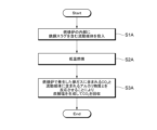
- a fluidized medium 130 containing iron and steel slag containing an alkaline substance is charged into the combustion furnace 100A of the CFB boiler 1A (medium charging step: S1A).
- the medium feeding step S1A is performed before the exhaust gas G is generated in the combustion furnace 100A.
- Periodic replenishment of the alkaline substance is preferred. That is, it is preferable that the medium feeding step S1A is periodically performed while the CFB boiler 1A is in operation.
- the central processing unit 200A of the CFB boiler 1A controls various configurations so that the combustion temperature in the combustion furnace 100A is 600 to 800 ° C., thereby realizing "low temperature combustion” in which CO 2 is easily immobilized ( Low temperature combustion stroke: S2A).
- the alkaline substance is calcium oxide (CaO)
- the following chemical reaction produces calcium carbonate (CaCO 3 ) as a carbonate while immobilizing CO 2 .
- the present invention is useful for efficiently recovering CO 2 contained in exhaust gas generated by a boiler.
Abstract
This boiler 1 is provided with a gasification furnace 2 and a CO2 recovery unit 100 for recovering CO2 from an exhaust gas generated in the gasification furnace 2. The CO2 recovery unit 100 includes a housing 110 equipped with an intake port 120 through which the exhaust gas is taken in and a fluidizing medium 130 which flows inside the housing 110, in which the fluidizing medium 130 comprises an iron and steel slag containing an alkaline substance. The CO2 recovery unit 100 is configured such that CO2 contained in the exhaust gas taken in the housing 110 through the intake port 120 is reacted with the alkaline substance contained in the fluidizing medium 130 to produce a carbonate, thereby recovering the CO2.
Description
本発明は、ボイラ及びCO2回収方法に関する。
The present invention relates to boilers and CO2 recovery methods.
従来より、燃焼炉で燃料を燃焼乃至ガス化させることによって得られる高温の排ガスの熱により蒸気を生成するボイラシステムが種々提案されている。現在においては、脱炭素化が社会課題となっていることを踏まえ、ボイラシステムで発生する排ガスに含まれるCO2を回収する試みがなされている。
2. Description of the Related Art Conventionally, various boiler systems have been proposed in which steam is generated from the heat of high-temperature exhaust gas obtained by burning or gasifying fuel in a combustion furnace. At present, in light of the fact that decarbonization has become a social issue, attempts are being made to recover CO 2 contained in exhaust gases generated in boiler systems.
例えば近年においては、酸素キャリアである金属酸化物(MeO)で燃料を酸化反応させ、還元された金属(Me)を空気で酸化して再度金属酸化物(MeO)として利用するケミカルルーピング燃焼技術が採用されている(特許文献1参照)。かかる技術を採用すると、反応生成物としてCO2と水分を得ることができ、CO2の回収が容易となる、とされている。
For example, in recent years, there has been a chemical looping combustion technology in which fuel is oxidized with metal oxide (MeO), which is an oxygen carrier, and the reduced metal (Me) is oxidized with air and reused as metal oxide (MeO). has been adopted (see Patent Document 1). Adopting such a technique is said to make it possible to obtain CO 2 and water as reaction products, facilitating the recovery of CO 2 .
しかし、酸素キャリア(金属酸化物(MeO))のコストが高いことから、特許文献1に記載されたようなケミカルルーピング燃焼技術が商業化されるまでには未だ時間を要するという現状がある。
However, due to the high cost of the oxygen carrier (metal oxide (MeO)), it will still take some time before the chemical looping combustion technology described in Patent Document 1 is commercialized.
本発明は、かかる事情に鑑みてなされたものであり、ボイラで発生する排ガスに含まれるCO2を効率良く回収することを目的とする。
The present invention has been made in view of such circumstances, and an object of the present invention is to efficiently recover CO 2 contained in exhaust gas generated in a boiler.
前記目的を達成するため、本発明に係る第一のボイラは、ガス化炉と、ガス化炉で発生する排ガスからCO2を回収するCO2回収部と、を備えるものであって、CO2回収部は、排ガスを取り入れるための取入口が設けられた筐体と、筐体の内部で流動する流動媒体と、を有し、流動媒体は、アルカリ物質を含有する鉄鋼スラグを含み、取入口を介して筐体の内部に取り入れた排ガスに含まれるCO2と流動媒体に含まれるアルカリ物質とを反応させることにより炭酸塩を生成してCO2を回収するように構成されているものである。アルカリ物質としては、酸化カルシウムや酸化マグネシウムを採用することができる。
In order to achieve the above object, a first boiler according to the present invention includes a gasification furnace and a CO 2 recovery section for recovering CO 2 from exhaust gas generated in the gasification furnace, wherein CO 2 The recovery unit has a housing provided with an intake for taking in the exhaust gas, and a fluid medium that flows inside the housing, the fluid medium containing steel slag containing an alkaline substance, and the intake CO2 contained in the exhaust gas introduced into the housing through the gas is reacted with the alkaline substance contained in the fluid medium to generate carbonate and recover the CO2 . . Calcium oxide and magnesium oxide can be used as the alkaline substance.
また、本発明に係る第一のCO2回収方法は、ガス化炉で発生する排ガスからCO2を回収する方法であって、ガス化炉に接続された筐体の内部に、アルカリ物質を含有する鉄鋼スラグを含む流動媒体を投入する媒体投入工程と、筐体の内部に取り入れた排ガスに含まれるCO2と流動媒体に含まれるアルカリ物質とを反応させることにより炭酸塩を生成してCO2を回収するCO2回収工程と、を含むものである。
A first method for recovering CO 2 according to the present invention is a method for recovering CO 2 from exhaust gas generated in a gasification furnace, wherein an alkaline substance is contained inside a housing connected to the gasification furnace. A medium charging step of charging a fluidizing medium containing iron and steel slag, and a reaction between the CO2 contained in the flue gas introduced into the housing and the alkaline substance contained in the fluidizing medium to generate carbonates and CO2 and a CO2 capture step that captures the .
かかる構成及び方法を採用すると、ガス化炉で発生する排ガスを筐体の内部に取り入れ、筐体内に取り入れた排ガスに含まれるCO2と、筐体内で流動する流動媒体(鉄鋼スラグ)に含まれるアルカリ物質と、を反応させることにより炭酸塩を生成してCO2を回収することができる。従って、残渣として認識されていた鉄鋼スラグを流動媒体として有効利用しつつ、低コストで効率良くCO2を回収することが可能となる。
By adopting such a configuration and method, the exhaust gas generated in the gasification furnace is taken into the interior of the housing, and the CO 2 contained in the exhaust gas taken into the housing and the fluid medium (steel slag) flowing in the housing. CO 2 can be recovered by reacting with an alkaline substance to form a carbonate. Therefore, it is possible to efficiently recover CO 2 at low cost while effectively using steel slag, which has been recognized as a residue, as a fluid medium.
本発明に係る第一のボイラにおいて、ガス化炉に接続される固気分離器と、固気分離器に接続される熱回収部と、をさらに備え、CO2回収部の筐体の取入口に、ガス化炉で発生する排ガスが固気分離器及び熱回収部を順次経由して流入するように構成することができる。かかる場合において、CO2回収部の筐体に排ガスを排出するための排出口を設けておき、排出口から排出された排ガスが戻り流路を介して熱回収部に戻されるように構成することもできる。
The first boiler according to the present invention, further comprising a solid-gas separator connected to the gasification furnace, and a heat recovery unit connected to the solid - gas separator, wherein Alternatively, the exhaust gas generated in the gasification furnace can be configured to flow in through the solid-gas separator and the heat recovery section in sequence. In such a case, an exhaust port for discharging the exhaust gas is provided in the housing of the CO 2 recovery unit, and the exhaust gas discharged from the exhaust port is returned to the heat recovery unit through the return flow path. can also
かかる構成を採用すると、CO2回収部の筐体の排出口から排出された排ガスを、戻り流路を介して熱回収部に戻して再利用することができる。このように、排ガスを熱回収部に戻して再利用することにより、排ガスに含まれる熱を効率良く回収することが可能となる。
By adopting such a configuration, the exhaust gas discharged from the exhaust port of the housing of the CO 2 recovery unit can be returned to the heat recovery unit via the return flow path and reused. In this way, by returning the exhaust gas to the heat recovery unit for reuse, it is possible to efficiently recover the heat contained in the exhaust gas.
前記目的を達成するため、本発明に係る第二のボイラは、ガス化炉と、ガス化炉の内部で流動する流動媒体と、を備えるものであって、流動媒体は、アルカリ物質を含有する鉄鋼スラグを含み、ガス化炉で発生する排ガスに含まれるCO2と流動媒体に含まれるアルカリ物質とを反応させることにより炭酸塩を生成してCO2を回収するように構成されているものである。アルカリ物質としては、酸化カルシウムや酸化マグネシウムを採用することができる。
In order to achieve the above object, a second boiler according to the present invention comprises a gasification furnace and a fluid medium that flows inside the gasification furnace, the fluid medium containing an alkaline substance. It contains iron and steel slag and is configured to recover CO2 by reacting CO2 contained in the exhaust gas generated in the gasification furnace with alkaline substances contained in the fluidized medium to produce carbonate. be. Calcium oxide and magnesium oxide can be used as the alkaline substance.
また、本発明に係る第二のCO2回収方法は、ガス化炉で発生する排ガスからCO2を回収する方法であって、ガス化炉の内部に、アルカリ物質を含有する鉄鋼スラグを含む流動媒体を投入する媒体投入工程と、排ガスに含まれるCO2と流動媒体に含まれるアルカリ物質とを反応させることにより炭酸塩を生成してCO2を回収するCO2回収工程と、を含むものである。
Further, a second CO 2 recovery method according to the present invention is a method for recovering CO 2 from exhaust gas generated in a gasification furnace, wherein a flow containing iron and steel slag containing an alkaline substance is placed inside the gasification furnace. It includes a medium charging step of charging a medium, and a CO2 recovery step of recovering CO2 by producing carbonate by reacting CO2 contained in the exhaust gas with an alkaline substance contained in the fluid medium .
かかる構成及び方法を採用すると、ガス化炉で発生する排ガスに含まれるCO2と、ガス化炉の内部で流動する流動媒体(鉄鋼スラグ)に含まれるアルカリ物質と、を反応させることにより炭酸塩を生成してCO2を回収することができる。従って、残渣として認識されていた鉄鋼スラグを流動媒体として有効利用しつつ、低コストで効率良くCO2を回収することが可能となる。
By adopting such a configuration and method, carbonates are produced by reacting CO 2 contained in the exhaust gas generated in the gasification furnace with alkaline substances contained in the fluid medium (steel slag) flowing inside the gasification furnace. can be generated to capture CO2 . Therefore, it is possible to efficiently recover CO 2 at low cost while effectively using steel slag, which has been recognized as a residue, as a fluid medium.
本発明によれば、ボイラで発生する排ガスに含まれるCO2を効率良く回収することが可能となる。
ADVANTAGE OF THE INVENTION According to this invention, it becomes possible to collect|recover CO2 contained in the flue gas which generate|occur|produces in a boiler efficiently.
以下、図面を参照して、本発明の各実施形態について説明する。なお、以下の各実施形態はあくまでも好適な適用例であって、本発明の適用範囲がこれに限定されるものではない。
Each embodiment of the present invention will be described below with reference to the drawings. It should be noted that each of the following embodiments is merely a suitable application example, and the scope of application of the present invention is not limited to this.
<第一実施形態>
まず、図1を用いて、本発明の第一実施形態に係る流動床式(CFB(Circulating Fluidized Bed)ボイラ(以下、「CFBボイラ」と称する)1について説明する。 <First embodiment>
First, a fluidized bed (CFB (Circulating Fluidized Bed) boiler (hereinafter referred to as "CFB boiler") 1 according to a first embodiment of the present invention will be described with reference to FIG.
CFBボイラ1は、燃焼炉2、第一のサイクロン分離器4、熱回収部6、第一のリターンライン8、CO2回収部100、第二のサイクロン分離器10、第二のリターンライン12、戻り流路14、中央処理装置200、等を備えている。
The CFB boiler 1 includes a combustion furnace 2, a first cyclone separator 4, a heat recovery section 6, a first return line 8, a CO2 recovery section 100, a second cyclone separator 10, a second return line 12, It includes a return channel 14, a central processing unit 200, and the like.
燃焼炉2は、外部循環型の流動層式燃焼炉であって、燃料を燃焼乃至ガス化させ密閉容器(図示されていない蒸気ドラム)内の水を加熱して蒸気を生成するものであり、本発明におけるガス化炉として機能する。燃焼炉2には、図示されていない燃料投入口を介して、各種燃料(例えば、モミ殻やEFB(Empty Fruit Bunches)等のバイオマス燃料、木屑、タイヤ、RPF等)が投入される。また、燃焼炉2には、燃料投入口を介して石英粒子を主成分とする流動媒体が投入されており、この流動媒体中に下部から空気が供給され、流動媒体が流動して流動床(以下「ベッド」という)Fが形成される。ベッドFの形成により、燃料の燃焼が促進される。なお、流動媒体には、砂を種(たね)としてバイオマス燃料中の成分が凝縮、融体、凝集して付着したり砂表面で化学反応したりして粒子形成されたボトムアッシュBAが含まれる。
The combustion furnace 2 is an external circulation fluidized bed combustion furnace that burns or gasifies fuel and heats water in a closed container (steam drum, not shown) to generate steam. It functions as a gasification furnace in the present invention. Various fuels (for example, biomass fuels such as rice husks and EFB (Empty Fruit Bunches), wood chips, tires, RPF, etc.) are introduced into the combustion furnace 2 through a fuel inlet (not shown). In the combustion furnace 2, a fluidized medium containing quartz particles as a main component is fed through a fuel inlet. hereinafter referred to as "bed") F is formed. The formation of the bed F promotes fuel combustion. The fluidized medium includes bottom ash BA, which is formed by condensing, melting, and aggregating components in biomass fuel with sand as a seed, or by chemically reacting on the sand surface to form particles. .
燃焼炉2で生じた燃焼ガス(以下、「排ガス」という)Gは、流動媒体の一部を随伴しながら燃焼炉2内を上昇する。燃焼炉2の上部には、排ガスを排出するガス出口2Aが設けられている。燃焼炉2の下部には、ボトムアッシュBAを排出するための図示されていない排出口が設けられている。なお、燃焼炉2の燃料投入口には、燃料の量、組成、種類、混焼比率、添加剤の供給量、流動媒体の供給量、の各々を変更することができる燃料供給調整機構が設けられており、燃焼炉2の排出口には、流動媒体の抜出量を変更することができる流動媒体排出調整機構が設けられている。これら燃料供給調整機構及び流動媒体排出調整機構が中央処理装置200によって制御されることにより、燃焼炉2に投入される燃料の量や燃焼炉2から抜き出される流動媒体の量が調整されることとなる。
Combustion gas (hereinafter referred to as "exhaust gas") G generated in the combustion furnace 2 rises inside the combustion furnace 2 while accompanying part of the fluid medium. A gas outlet 2A for discharging exhaust gas is provided in the upper portion of the combustion furnace 2 . A discharge port (not shown) for discharging the bottom ash BA is provided in the lower part of the combustion furnace 2 . The fuel inlet of the combustion furnace 2 is provided with a fuel supply adjustment mechanism capable of changing each of the amount, composition, type of fuel, co-firing ratio, additive supply amount, and fluid medium supply amount. At the discharge port of the combustion furnace 2, a fluidized medium discharge adjustment mechanism capable of changing the amount of the fluidized medium discharged is provided. The central processing unit 200 controls the fuel supply adjustment mechanism and fluidized medium discharge adjustment mechanism to adjust the amount of fuel introduced into the combustion furnace 2 and the amount of fluidized medium extracted from the combustion furnace 2. becomes.
第一のサイクロン分離器4は、排ガスGから固形物を分離するものであり、本発明における固気分離器として機能する。第一のサイクロン分離器4は、燃焼炉2に隣接して配置されており、ガス出口2Aを介して燃焼炉2に接続されている。第一のサイクロン分離器4は、燃焼炉2から排出された排ガスG及び排ガスGに随伴された流動媒体を受け入れ、遠心分離作用によって排ガスGと流動媒体とを分離し、流動媒体を燃焼炉2に戻し、排ガスGを熱回収部6に送り込む。第一のサイクロン分離器4には、第一のリターンライン8が接続されている。
The first cyclone separator 4 separates solids from the exhaust gas G and functions as a solid-gas separator in the present invention. A first cyclone separator 4 is arranged adjacent to the combustion furnace 2 and is connected to the combustion furnace 2 via a gas outlet 2A. The first cyclone separator 4 receives the exhaust gas G discharged from the combustion furnace 2 and the fluidized medium accompanying the exhaust gas G, separates the exhaust gas G from the fluidized medium by centrifugal separation, and transfers the fluidized medium to the combustion furnace 2. , and the exhaust gas G is sent to the heat recovery unit 6. A first return line 8 is connected to the first cyclone separator 4 .
熱回収部6には、排ガスGの熱を熱回収するように機能するものであり、各種熱交換チューブ(例えば、過熱蒸気を発生させる過熱器やボイラ給水を予熱する節炭器等)が配置されている。過熱器は、排ガスの熱を用いて蒸気を過熱して過熱蒸気を生成するものである。過熱蒸気は、図示されていない配管を通り、CFBボイラ1外の図示されていないタービン等に供給されて発電に利用される。節炭器は、排ガスの熱をボイラ給水に伝熱して、ボイラ給水を予熱するものである。
The heat recovery unit 6 functions to recover the heat of the exhaust gas G, and various heat exchange tubes (for example, a superheater for generating superheated steam, an economizer for preheating boiler feed water, etc.) are arranged. It is The superheater uses the heat of the exhaust gas to superheat the steam to produce superheated steam. The superheated steam passes through piping (not shown), is supplied to a turbine (not shown) outside the CFB boiler 1, and is used for power generation. The economizer transfers the heat of the exhaust gas to the boiler feed water to preheat the boiler feed water.
第一のリターンライン8は、第一のサイクロン分離器4で排ガスGから分離された飛灰(すなわち排ガスGから分離された流動媒体の一部)を燃焼炉2の下部に戻すように機能するものである。第一のリターンライン8は、燃焼炉2の下部に接続された管路からなり、その途中上にはループシール8Aが設けられている。ループシール8Aは、燃焼炉2からの排ガスGの逆流を防止する設備である。ループシール8A内には、第一のサイクロン分離器4から送り込まれた流動媒体が蓄積される。また、ループシール8A内の流動媒体は、ループシール8Aの出口のリターンシュート部8Bから燃焼炉2内に投入される。
The first return line 8 functions to return the fly ash separated from the exhaust gas G by the first cyclone separator 4 (that is, part of the fluidized medium separated from the exhaust gas G) to the lower part of the combustion furnace 2. It is a thing. The first return line 8 consists of a pipeline connected to the lower part of the combustion furnace 2, and a loop seal 8A is provided on the way. The loop seal 8A is equipment that prevents the exhaust gas G from the combustion furnace 2 from flowing back. Fluid medium fed from the first cyclone separator 4 is accumulated in the loop seal 8A. Further, the fluid medium in the loop seal 8A is introduced into the combustion furnace 2 from the return chute portion 8B at the exit of the loop seal 8A.
CO2回収部100は、燃焼炉2で発生する排ガスGからCO2を回収するように機能するものである。CO2回収部100は、排ガスGを取り入れるための取入口120が設けられた筐体110と、筐体110の内部で流動する流動媒体130と、を有しており、筐体110の取入口120に、燃焼炉2で発生する排ガスGが第一のサイクロン分離器4及び熱回収部6を順次経由して流入するように構成されている。熱回収部6と筐体110の取入口120とを接続する接続管121には、制御可能な開閉弁122が設けられている。中央処理装置200によって開閉弁122を開くように制御することにより、熱回収部6から筐体110への排ガスGの流入が可能となる一方、中央処理装置200によって開閉弁122を閉じるように制御することにより、熱回収部6から筐体110への排ガスGの流入が遮断されるようになっている。
The CO 2 recovery unit 100 functions to recover CO 2 from the exhaust gas G generated in the combustion furnace 2 . The CO 2 recovery unit 100 has a housing 110 provided with an intake 120 for taking in the exhaust gas G, and a fluid medium 130 that flows inside the housing 110. The intake of the housing 110 120, the exhaust gas G generated in the combustion furnace 2 flows through the first cyclone separator 4 and the heat recovery section 6 in sequence. A connection pipe 121 connecting the heat recovery unit 6 and the intake port 120 of the housing 110 is provided with a controllable on-off valve 122 . By controlling the opening/closing valve 122 to be opened by the central processing unit 200, the flow of the exhaust gas G from the heat recovery unit 6 to the housing 110 becomes possible, while the central processing unit 200 is controlling the opening/closing valve 122 to be closed. By doing so, the inflow of the exhaust gas G from the heat recovery unit 6 to the housing 110 is blocked.
本実施形態においては、燃焼炉2の内部に投入されるような流動媒体(石英粒子等を主成分としたもの)に鉄鋼スラグを含有させたものを流動媒体130として採用している。鉄鋼スラグには、酸化カルシウム(CaO)や酸化マグネシウム(MgO)等のアルカリ物質が含有されており、かかるアルカリ物質が、排ガスGに含まれるCO2と反応することにより炭酸塩が生成され、CO2を固定化して回収することができるようになっている。例えば、アルカリ物質が酸化カルシウム(CaO)である場合には、以下の化学反応により炭酸塩としての炭酸カルシウム(CaCO3)が生成される一方、CO2が固定化される。
CaO+CO2 → CaCO3 In the present embodiment, a fluidized medium (mainly composed of quartz particles or the like) that is introduced into thecombustion furnace 2 and containing iron and steel slag is used as the fluidized medium 130 . Iron and steel slag contains alkaline substances such as calcium oxide (CaO) and magnesium oxide (MgO), and such alkaline substances react with CO 2 contained in the exhaust gas G to produce carbonates. 2 can be immobilized and recovered. For example, when the alkaline substance is calcium oxide (CaO), the following chemical reaction produces calcium carbonate (CaCO 3 ) as a carbonate, while immobilizing CO 2 .
CaO+ CO2 → CaCO3
CaO+CO2 → CaCO3 In the present embodiment, a fluidized medium (mainly composed of quartz particles or the like) that is introduced into the
CaO+ CO2 → CaCO3
流動媒体130は、燃焼炉2で発生する排ガスGが筐体110の内部に取り入れられる前に筐体110の内部に投入されており、流動媒体130中に下部から空気が供給されることにより、流動媒体130が流動してCO2の回収が促進されるようになっている。また、CO2とアルカリ物質との反応が進むことにより流動媒体130に含まれるアルカリ物質の割合が漸次減少するため、流動媒体130に定期的に鉄鋼スラグを供給することによりアルカリ物質を定期的に補充することが好ましい。なお、鉄鋼スラグのみを流動媒体130として採用してもよい。
The fluidized medium 130 is introduced into the housing 110 before the exhaust gas G generated in the combustion furnace 2 is introduced into the housing 110. A flow medium 130 is adapted to flow to facilitate CO2 capture. In addition, as the reaction between CO 2 and the alkaline substance progresses, the proportion of the alkaline substance contained in the fluid medium 130 gradually decreases. Supplementation is preferred. Note that only steel slag may be employed as the fluid medium 130 .
CO2回収部100の筐体110の下部には、CO2の回収(固定化)に伴って生成された炭酸塩を含むボトムアッシュBAを排出するための図示されていない排出口が設けられている。かかる排出口には、ボトムアッシュBAの抜出量を変更することができるボトムアッシュ排出調整機構が設けられており、かかるボトムアッシュ排出調整機構が中央処理装置200によって制御されることにより、筐体110から抜き出されるボトムアッシュBA(及びそれに含まれる炭酸塩)の量が調整される。
At the bottom of the housing 110 of the CO 2 recovery unit 100, a discharge port (not shown) is provided for discharging the bottom ash BA containing carbonates produced along with the CO 2 recovery (fixation). there is The discharge port is provided with a bottom ash discharge adjustment mechanism capable of changing the amount of bottom ash BA withdrawn. The amount of bottom ash BA (and carbonate contained therein) extracted from 110 is adjusted.
また、CO2回収部100の筐体110には、排ガスGを排出するための排出口140が設けられている。筐体110の排出口140から排出された排ガスGは、第二のサイクロン分離器10を経由して戻り流路14に流入するようになっている。戻り流路14に流入した排ガスGは、吸引ファン14Aによって吸引され、熱回収部6に戻されて再度熱回収に供される。
Further, the housing 110 of the CO 2 recovery unit 100 is provided with an outlet 140 for discharging the exhaust gas G. As shown in FIG. The exhaust gas G discharged from the discharge port 140 of the housing 110 passes through the second cyclone separator 10 and flows into the return flow path 14 . The exhaust gas G that has flowed into the return flow path 14 is sucked by the suction fan 14A and returned to the heat recovery section 6 for heat recovery again.
第二のサイクロン分離器10は、CO2回収部100に隣接して配置されており、排出口140を介して筐体110に接続されている。第二のサイクロン分離器10は、CO2回収部100の筐体110から排出された排ガスG及び排ガスGに随伴された流動媒体130を受け入れ、遠心分離作用によって排ガスGと流動媒体130とを分離し、流動媒体130を筐体110に戻し、戻り流路14を経由して排ガスGを熱回収部6に送り込む。第二のサイクロン分離器10には、第二のリターンライン12が接続されている。
The second cyclone separator 10 is arranged adjacent to the CO 2 capture section 100 and is connected to the housing 110 via the outlet 140 . The second cyclone separator 10 receives the exhaust gas G discharged from the housing 110 of the CO 2 recovery unit 100 and the fluid medium 130 accompanying the exhaust gas G, and separates the exhaust gas G and the fluid medium 130 by centrifugal separation. Then, the fluid medium 130 is returned to the housing 110 , and the exhaust gas G is sent to the heat recovery section 6 via the return flow path 14 . A second return line 12 is connected to the second cyclone separator 10 .
第二のリターンライン12は、第二のサイクロン分離器10で排ガスGから分離された飛灰(すなわち排ガスGから分離された流動媒体130の一部)をCO2回収部100の下部に戻すように機能するものである。第二のリターンライン12は、CO2回収部100の筐体110の下部に接続された管路からなり、その途中上にはループシール12Aが設けられている。ループシール12Aは、筐体110からの排ガスGの逆流を防止する設備である。ループシール12A内には、第二のサイクロン分離器10から送り込まれた流動媒体130が蓄積される。また、ループシール12A内の流動媒体130は、ループシール12Aの出口のリターンシュート部12Bから筐体110内に投入される。
The second return line 12 returns the fly ash separated from the exhaust gas G in the second cyclone separator 10 (that is, part of the fluidized medium 130 separated from the exhaust gas G) to the lower part of the CO 2 recovery unit 100. function. The second return line 12 consists of a pipeline connected to the lower part of the housing 110 of the CO 2 recovery unit 100, and a loop seal 12A is provided on the way. The loop seal 12</b>A is equipment that prevents backflow of the exhaust gas G from the housing 110 . Fluid medium 130 sent from the second cyclone separator 10 accumulates in the loop seal 12A. Also, the fluid medium 130 in the loop seal 12A is introduced into the housing 110 from the return chute portion 12B at the exit of the loop seal 12A.
熱回収部6の内部の排ガスGの一部(CO2回収部100によってCO2が回収された排ガスGを含む)は、吸引ファン18によって吸引されることによりバグフィルタ16に流入し、排ガスGに含まれる煤塵等の微粒子がバグフィルタ16で濾過捕集された後、煙突20からCFBボイラ1外に排出される。バグフィルタ16によって捕集された煤塵(フライアッシュFAを含む)は、バグフィルタ16の下方に設けられた図示されていない排出口から回収される。
A part of the exhaust gas G inside the heat recovery unit 6 (including the exhaust gas G from which CO 2 has been recovered by the CO 2 recovery unit 100) is sucked by the suction fan 18 to flow into the bag filter 16, where the exhaust gas G After being filtered and collected by the bag filter 16, fine particles such as soot and dust contained in the CFB boiler 1 are discharged from the chimney 20 to the outside of the CFB boiler 1. Dust (including fly ash FA) collected by the bag filter 16 is recovered from an unillustrated discharge port provided below the bag filter 16 .
中央処理装置200は、CFBボイラ1の各種構成を統合制御するものであり、各種制御プログラムや各種制御用データ等を格納するメモリや、各種制御プログラムを実行するプロセッサ等によって構成されている。例えば、中央処理装置200は、燃料供給調整機構を制御することにより燃焼炉2に投入される燃料の量を調整したり、流動媒体排出調整機構を制御することにより燃焼炉2から抜き出される流動媒体の量を調整したり、投入される燃料の種類や量に応じて燃焼炉2の燃焼温度や燃焼時間を制御したり、CO2回収部100の筐体110内の流動媒体130中に供給する空気の量を調整することにより流動媒体130の流動態様を変更したり、ボトムアッシュ排出調整機構を制御することによりCO2回収部100の筐体110から抜き出されるボトムアッシュBA(及びそれに含まれる炭酸塩)の量を調整したりすることができるようになっている。
The central processing unit 200 integrally controls various components of the CFB boiler 1, and includes a memory for storing various control programs, various control data, and the like, a processor for executing various control programs, and the like. For example, the central processing unit 200 adjusts the amount of fuel supplied to the combustion furnace 2 by controlling the fuel supply adjustment mechanism, and controls the fluidized medium discharge adjustment mechanism to control the fluid flow extracted from the combustion furnace 2. It is possible to adjust the amount of medium, control the combustion temperature and combustion time of the combustion furnace 2 according to the type and amount of fuel to be fed, and supply the fluid medium 130 in the housing 110 of the CO 2 recovery unit 100. The bottom ash BA extracted from the housing 110 of the CO 2 recovery unit 100 (and It is now possible to adjust the amount of carbonate that is released.
次に、図2のフローチャートを用いて、本実施形態に係るCO2回収方法(本実施形態に係るCFBボイラ1の燃焼炉2で発生する排ガスGからCO2を回収する方法)について説明する。
Next, a CO 2 recovery method according to this embodiment (a method for recovering CO 2 from the exhaust gas G generated in the combustion furnace 2 of the CFB boiler 1 according to this embodiment) will be described using the flowchart of FIG. 2 .
まず、CFBボイラ1の燃焼炉2に接続されたCO2回収部100の筐体110の内部に、アルカリ物質を含有する鉄鋼スラグを含む流動媒体130を投入する(媒体投入工程:S1)。媒体投入工程S1は、燃焼炉2で発生する排ガスGが筐体110の内部に取り入れられる前に実施される。なお、既に述べたように、CO2とアルカリ物質との反応が進むことにより流動媒体130に含まれるアルカリ物質の割合が漸次減少するため、CO2回収部100の筐体110の内部に定期的に鉄鋼スラグを供給することによりアルカリ物質を定期的に補充することが好ましい。すなわち、媒体投入工程S1は、CFBボイラ1の稼動中に定期的に実施されることが好ましい。
First, a fluidized medium 130 containing steel slag containing an alkaline substance is introduced into the housing 110 of the CO 2 recovery unit 100 connected to the combustion furnace 2 of the CFB boiler 1 (medium introduction step: S1). The medium charging step S1 is performed before the exhaust gas G generated in the combustion furnace 2 is introduced into the housing 110 . As already described, as the reaction between CO 2 and alkaline substances progresses , the ratio of the alkaline substance contained in the fluid medium 130 gradually decreases. Preferably, the alkaline material is periodically replenished by supplying steel slag to the . That is, it is preferable that the medium feeding step S1 is periodically performed while the CFB boiler 1 is in operation.
次いで、CO2回収部100の筐体110の内部に取り入れた排ガスに含まれるCO2と、媒体投入工程S1を経て筐体110の内部に投入された流動媒体130に含まれるアルカリ物質と、を反応させることにより、炭酸塩を生成してCO2を回収する(CO2回収工程)。既に述べたように、アルカリ物質が酸化カルシウム(CaO)である場合には、以下の化学反応により炭酸塩としての炭酸カルシウム(CaCO3)が生成される一方、CO2が固定化される。
CaO+CO2 → CaCO3 Next, the CO 2 contained in the exhaust gas introduced into thehousing 110 of the CO 2 recovery unit 100 and the alkaline substance contained in the fluid medium 130 introduced into the housing 110 through the medium introduction step S1 are separated. The reaction produces carbonate and recovers CO2 ( CO2 recovery step). As already mentioned, when the alkaline substance is calcium oxide (CaO), the following chemical reaction produces calcium carbonate (CaCO 3 ) as a carbonate while immobilizing CO 2 .
CaO+ CO2 → CaCO3
CaO+CO2 → CaCO3 Next, the CO 2 contained in the exhaust gas introduced into the
CaO+ CO2 → CaCO3
以上説明した実施形態に係るCFBボイラ1においては、燃焼炉2で発生する排ガスGをCO2回収部100の筐体110の内部に取り入れ、筐体110内に取り入れた排ガスGに含まれるCO2と、筐体110内で流動する流動媒体130(鉄鋼スラグ)に含まれるアルカリ物質と、を反応させることにより炭酸塩を生成してCO2を回収することができる。従って、残渣として認識されていた鉄鋼スラグを流動媒体130として有効利用しつつ、低コストで効率良くCO2を回収することが可能となる。
In the CFB boiler 1 according to the embodiment described above, the exhaust gas G generated in the combustion furnace 2 is introduced into the housing 110 of the CO 2 recovery unit 100, and the CO 2 contained in the exhaust gas G introduced into the housing 110 is and an alkaline substance contained in the fluid medium 130 (steel slag) flowing within the housing 110 react with each other to generate carbonate and recover CO 2 . Therefore, it is possible to efficiently recover CO 2 at a low cost while effectively using steel slag, which has been recognized as a residue, as the fluidizing medium 130 .
また、以上説明した実施形態に係るCFBボイラ1においては、CO2回収部100の筐体110の排出口140から排出された排ガスGを、戻り流路14を介して熱回収部6に戻して再利用することができる。このように、排ガスGを熱回収部6に戻して再利用することにより、排ガスGに含まれる熱を効率良く回収することが可能となる。
Further, in the CFB boiler 1 according to the embodiment described above, the exhaust gas G discharged from the discharge port 140 of the housing 110 of the CO 2 recovery unit 100 is returned to the heat recovery unit 6 through the return flow path 14. Can be reused. By returning the exhaust gas G to the heat recovery unit 6 for reuse in this way, it is possible to efficiently recover the heat contained in the exhaust gas G.
<第二実施形態>
続いて、本発明の第二実施形態について説明する。 <Second embodiment>
Next, a second embodiment of the invention will be described.
続いて、本発明の第二実施形態について説明する。 <Second embodiment>
Next, a second embodiment of the invention will be described.
まず、図3を用いて、本発明の第二実施形態に係るCFBボイラ1Aについて説明する。本実施形態に係るCFBボイラ1Aは、燃焼炉100A、第一のサイクロン分離器4、熱回収部6、第一のリターンライン8、中央処理装置200A、等を備えており、燃焼炉100Aの内部に鉄鋼スラグを含む流動媒体130を投入することにより、燃焼炉100Aで発生する排ガスに含まれるCO2を鉄鋼スラグに含まれるアルカリ物質と反応させて回収するように構成したものである。換言すれば、本実施形態に係るCFBボイラ1Aは、燃焼炉100A自体が「CO2回収部」として機能するものである。
First, a CFB boiler 1A according to a second embodiment of the present invention will be described using FIG. The CFB boiler 1A according to the present embodiment includes a combustion furnace 100A, a first cyclone separator 4, a heat recovery unit 6, a first return line 8, a central processing unit 200A, etc., and the inside of the combustion furnace 100A By introducing a fluidized medium 130 containing iron and steel slag into the furnace 100A, the CO 2 contained in the exhaust gas generated in the combustion furnace 100A is reacted with the alkaline substance contained in the iron and steel slag and recovered. In other words, in the CFB boiler 1A according to this embodiment, the combustion furnace 100A itself functions as a "CO 2 recovery section".
燃焼炉100Aは、第一実施形態における燃焼炉2と同様に、外部循環型の流動層式燃焼炉であって、燃料を燃焼乃至ガス化させ密閉容器内の水を加熱して蒸気を生成するものであり、本発明におけるガス化炉として機能する。燃焼炉100Aには、図示されていない燃料投入口を介して、各種燃料(例えば、モミ殻やEFB(Empty Fruit Bunches)等のバイオマス燃料、木屑、タイヤ、RPF等)が投入される。燃焼炉100Aには、燃料投入口を介して石英粒子を主成分とする流動媒体130が投入されており、この流動媒体130中に下部から空気が供給され、流動媒体130が流動して流動床(以下「ベッド」という)Fが形成される。ベッドFの形成により、燃料の燃焼が促進される。なお、流動媒体130には、砂を種(たね)としてバイオマス燃料中の成分が凝縮、融体、凝集して付着したり砂表面で化学反応したりして粒子形成されたボトムアッシュBAが含まれる。
The combustion furnace 100A, like the combustion furnace 2 in the first embodiment, is an external circulation type fluidized bed combustion furnace that burns or gasifies fuel and heats water in a sealed container to generate steam. It functions as a gasification furnace in the present invention. Various fuels (for example, biomass fuels such as rice husks and EFB (Empty Fruit Bunches), wood chips, tires, RPF, etc.) are introduced into the combustion furnace 100A through a fuel inlet (not shown). A fluidized medium 130 mainly composed of quartz particles is introduced into the combustion furnace 100A through a fuel inlet. F (hereinafter referred to as "bed") is formed. The formation of the bed F promotes fuel combustion. The fluidized medium 130 includes bottom ash BA, which is formed by condensing, melting, and aggregating components of the biomass fuel with sand as a seed, or by chemically reacting on the sand surface to form particles. be
本実施形態においては、燃焼炉100Aの内部に投入される流動媒体130に鉄鋼スラグを含有させている。鉄鋼スラグには、酸化カルシウム(CaO)や酸化マグネシウム(MgO)等のアルカリ物質が含有されており、かかるアルカリ物質が、燃焼炉100Aで発生する排ガスGに含まれるCO2と反応することにより炭酸塩が生成され、CO2を固定化して回収することができるようになっている。例えば、アルカリ物質が酸化カルシウム(CaO)である場合には、以下の化学反応により炭酸塩としての炭酸カルシウム(CaCO3)が生成される一方、CO2が固定化される。
CaO+CO2 → CaCO3 In this embodiment, iron and steel slag is contained in the fluidized medium 130 that is introduced into thecombustion furnace 100A. Iron and steel slag contains alkali substances such as calcium oxide (CaO) and magnesium oxide (MgO), and such alkali substances react with CO 2 contained in the exhaust gas G generated in the combustion furnace 100A to form carbonic acid. A salt is produced to fix the CO2 so that it can be recovered. For example, when the alkaline substance is calcium oxide (CaO), the following chemical reaction produces calcium carbonate (CaCO 3 ) as a carbonate, while immobilizing CO 2 .
CaO+ CO2 → CaCO3
CaO+CO2 → CaCO3 In this embodiment, iron and steel slag is contained in the fluidized medium 130 that is introduced into the
CaO+ CO2 → CaCO3
流動媒体130は、燃焼炉100Aで排ガスGが発生する前に燃焼炉100Aの内部に投入されている。また、CO2とアルカリ物質との反応が進むことにより流動媒体130に含まれるアルカリ物質の割合が漸次減少するため、燃焼炉100Aの内部に定期的に鉄鋼スラグを供給することによりアルカリ物質を定期的に補充することが好ましい。なお、鉄鋼スラグのみを流動媒体130として採用してもよい。
The fluidized medium 130 is introduced into the combustion furnace 100A before the exhaust gas G is generated in the combustion furnace 100A. In addition, as the reaction between CO 2 and the alkaline substance progresses, the ratio of the alkaline substance contained in the fluid medium 130 gradually decreases. It is preferable to replenish Note that only steel slag may be employed as the fluid medium 130 .
燃焼炉100Aで生じた排ガスGは、流動媒体130の一部を随伴しながら燃焼炉100A内を上昇する。燃焼炉100Aの上部には、排ガスを排出するガス出口2Aが設けられている。燃焼炉100Aの下部には、CO2の回収(固定化)に伴って生成された炭酸塩を含むボトムアッシュBAを排出するための図示されていない排出口が設けられている。なお、燃焼炉100Aの燃料投入口には、燃料の量、組成、種類、混焼比率、添加剤の供給量、流動媒体130の供給量、の各々を変更することができる燃料供給調整機構が設けられている。また、燃焼炉100Aの排出口には、ボトムアッシュBAの抜出量を変更することができるボトムアッシュ排出調整機構が設けられている。これら燃料供給調整機構及びボトムアッシュ排出調整機構が中央処理装置200Aによって制御されることにより、燃焼炉100Aに投入される燃料の量や燃焼炉100Aから抜き出されるボトムアッシュBA(及びそれに含まれる炭酸塩)の量が調整されることとなる。
The exhaust gas G generated in the combustion furnace 100A rises inside the combustion furnace 100A while accompanying part of the fluidized medium 130. As shown in FIG. A gas outlet 2A for discharging exhaust gas is provided in the upper portion of the combustion furnace 100A. At the bottom of the combustion furnace 100A, a discharge port (not shown) is provided for discharging the bottom ash BA containing carbonate generated along with the recovery (fixation) of CO 2 . The fuel inlet of the combustion furnace 100A is provided with a fuel supply adjustment mechanism capable of changing each of the amount, composition, type of fuel, co-firing ratio, additive supply amount, and fluid medium 130 supply amount. It is Further, a bottom ash discharge adjustment mechanism capable of changing the amount of bottom ash BA to be discharged is provided at the discharge port of the combustion furnace 100A. By controlling these fuel supply adjustment mechanism and bottom ash discharge adjustment mechanism by the central processing unit 200A, the amount of fuel put into the combustion furnace 100A and the bottom ash BA extracted from the combustion furnace 100A (and carbonic acid contained therein) salt) will be adjusted.
第一のサイクロン分離器4、熱回収部6及び第一のリターンライン8は、第一実施形態におけるものと実質的に同一であるので詳細な説明を省略する。熱回収部6の内部の排ガスGの一部(燃焼炉100AにおいてCO2が回収された排ガスGを含む)は、第一実施形態と同様に、吸引ファン18によって吸引されることによりバグフィルタ16に流入し、排ガスGに含まれる煤塵等の微粒子がバグフィルタ16で濾過捕集された後、煙突20からCFBボイラ1A外に排出される。バグフィルタ16によって捕集された煤塵(フライアッシュFAを含む)は、第一実施形態と同様に、バグフィルタ16の下方に設けられた図示されていない排出口から回収される。
The first cyclone separator 4, the heat recovery section 6, and the first return line 8 are substantially the same as those in the first embodiment, so detailed description thereof will be omitted. A part of the exhaust gas G inside the heat recovery unit 6 (including the exhaust gas G from which CO 2 has been recovered in the combustion furnace 100A) is sucked by the suction fan 18 to pass through the bag filter 16 as in the first embodiment. , and fine particles such as dust contained in the exhaust gas G are filtered and collected by the bag filter 16, and then discharged from the chimney 20 to the outside of the CFB boiler 1A. Dust (including fly ash FA) collected by the bag filter 16 is recovered from an unillustrated discharge port provided below the bag filter 16, as in the first embodiment.
中央処理装置200Aは、CFBボイラ1Aの各種構成を統合制御するものであり、各種制御プログラムや各種制御用データ等を格納するメモリや、各種制御プログラムを実行するプロセッサ等によって構成されている。例えば、中央処理装置200Aは、燃料供給調整機構を制御することにより燃焼炉100Aに投入される燃料の量を調整したり、ボトムアッシュ排出調整機構を制御することにより燃焼炉100Aから抜き出されるボトムアッシュBA(及びそれに含まれる炭酸塩)の量を調整したり、投入される燃料の種類に応じて燃焼炉100Aの燃焼温度や燃料投入量を制御したりすることができるようになっている。特に、本実施形態における中央処理装置200Aは、燃焼炉100Aにおける燃焼温度を600~800℃に設定することにより、CO2が固定化され易い「低温燃焼」を実現させるように機能する。
The central processing unit 200A integrally controls various components of the CFB boiler 1A, and includes a memory for storing various control programs and various control data, a processor for executing various control programs, and the like. For example, the central processing unit 200A controls the fuel supply adjustment mechanism to adjust the amount of fuel supplied to the combustion furnace 100A, and controls the bottom ash discharge adjustment mechanism to control the bottom ash extracted from the combustion furnace 100A. The amount of ash BA (and the carbonate contained therein) can be adjusted, and the combustion temperature and fuel input amount of the combustion furnace 100A can be controlled according to the type of fuel to be input. In particular, the central processing unit 200A in this embodiment functions to achieve "low-temperature combustion" in which CO 2 is easily fixed by setting the combustion temperature in the combustion furnace 100A to 600-800°C.
次に、図4のフローチャートを用いて、本実施形態に係るCO2回収方法(本実施形態に係るCFBボイラ1Aの燃焼炉100Aで発生する排ガスGからCO2を回収する方法)について説明する。
Next, a CO 2 recovery method according to this embodiment (a method for recovering CO 2 from the exhaust gas G generated in the combustion furnace 100A of the CFB boiler 1A according to this embodiment) will be described with reference to the flowchart of FIG.
まず、CFBボイラ1Aの燃焼炉100Aの内部に、アルカリ物質を含有する鉄鋼スラグを含む流動媒体130を投入する(媒体投入工程:S1A)。媒体投入工程S1Aは、燃焼炉100Aで排ガスGが発生する前に実施される。なお、既に述べたように、CO2とアルカリ物質との反応が進むことにより流動媒体130に含まれるアルカリ物質の割合が漸次減少するため、燃焼炉100Aに定期的に鉄鋼スラグを供給することによりアルカリ物質を定期的に補充することが好ましい。すなわち、媒体投入工程S1Aは、CFBボイラ1Aの稼動中に定期的に実施されることが好ましい。
First, a fluidized medium 130 containing iron and steel slag containing an alkaline substance is charged into the combustion furnace 100A of the CFB boiler 1A (medium charging step: S1A). The medium feeding step S1A is performed before the exhaust gas G is generated in the combustion furnace 100A. As already described, as the reaction between CO 2 and alkaline substances progresses, the proportion of alkaline substances contained in the fluidized medium 130 gradually decreases. Periodic replenishment of the alkaline substance is preferred. That is, it is preferable that the medium feeding step S1A is periodically performed while the CFB boiler 1A is in operation.
次いで、CFBボイラ1Aの中央処理装置200Aが、燃焼炉100Aにおける燃焼温度が600~800℃になるように各種構成を制御することにより、CO2が固定化され易い「低温燃焼」を実現させる(低温燃焼行程:S2A)。
Next, the central processing unit 200A of the CFB boiler 1A controls various configurations so that the combustion temperature in the combustion furnace 100A is 600 to 800 ° C., thereby realizing "low temperature combustion" in which CO 2 is easily immobilized ( Low temperature combustion stroke: S2A).
次いで、燃焼炉100Aの内部における低温燃焼(低温燃焼行程S2A)によって発生した排ガスに含まれるCO2と、媒体投入工程S1Aを経て燃焼炉100Aの内部に投入された流動媒体130に含まれるアルカリ物質と、を反応させることにより、炭酸塩を生成してCO2を回収する(CO2回収工程:S3A)。既に述べたように、アルカリ物質が酸化カルシウム(CaO)である場合には、以下の化学反応により炭酸塩としての炭酸カルシウム(CaCO3)が生成される一方、CO2が固定化される。
CaO+CO2 → CaCO3 Next, the CO 2 contained in the exhaust gas generated by the low-temperature combustion (low-temperature combustion step S2A) inside thecombustion furnace 100A, and the alkali substance contained in the fluidized medium 130 introduced into the combustion furnace 100A through the medium introduction step S1A. and are reacted to produce carbonate and recover CO 2 (CO 2 recovery step: S3A). As already mentioned, when the alkaline substance is calcium oxide (CaO), the following chemical reaction produces calcium carbonate (CaCO 3 ) as a carbonate while immobilizing CO 2 .
CaO+ CO2 → CaCO3
CaO+CO2 → CaCO3 Next, the CO 2 contained in the exhaust gas generated by the low-temperature combustion (low-temperature combustion step S2A) inside the
CaO+ CO2 → CaCO3
以上説明した実施形態に係るCFBボイラ1Aにおいては、燃焼炉100Aで発生する排ガスGに含まれるCO2と、燃焼炉100Aの内部で流動する流動媒体130(鉄鋼スラグ)に含まれるアルカリ物質と、を反応させることにより炭酸塩を生成してCO2を回収することができる。従って、残渣として認識されていた鉄鋼スラグを流動媒体130として有効利用しつつ、低コストで効率良くCO2を回収することが可能となる。
In the CFB boiler 1A according to the embodiment described above, CO 2 contained in the exhaust gas G generated in the combustion furnace 100A, alkaline substances contained in the fluidized medium 130 (steel slag) flowing inside the combustion furnace 100A, can be reacted to produce carbonate and recover CO2 . Therefore, it is possible to efficiently recover CO 2 at a low cost while effectively using steel slag, which has been recognized as a residue, as the fluidizing medium 130 .
本発明は、以上の各実施形態に限定されるものではなく、これら実施形態に当業者が適宜設計変更を加えたものも、本発明の特徴を備えている限り、本発明の範囲に包含される。すなわち、前記各実施形態が備える各要素及びその配置、材料、条件、形状、サイズ等は、例示したものに限定されるわけではなく適宜変更することができる。また、前記各実施形態が備える各要素は、技術的に可能な限りにおいて組み合わせることができ、これらを組み合わせたものも本発明の特徴を含む限り本発明の範囲に包含される。
The present invention is not limited to the above-described embodiments, and any design modifications made by those skilled in the art to these embodiments are also included in the scope of the present invention as long as they have the features of the present invention. be. That is, each element provided in each of the above embodiments and its arrangement, material, conditions, shape, size, etc. are not limited to those illustrated and can be changed as appropriate. Moreover, each element provided in each of the above-described embodiments can be combined as long as it is technically possible, and a combination of these is also included in the scope of the present invention as long as it includes the features of the present invention.
本発明は、ボイラで発生する排ガスに含まれるCO2を効率良く回収する際に有用である。
INDUSTRIAL APPLICABILITY The present invention is useful for efficiently recovering CO 2 contained in exhaust gas generated by a boiler.
1・1A…CFBボイラ
2…燃焼炉(ガス化炉)
4…第一のサイクロン分離器(固気分離器)
6…熱回収部
14…戻り流路
100…CO2回収部
100A…燃焼炉(ガス化炉)
110…筐体
120…取入口
130…流動媒体
140…排出口
S1・S1A…媒体投入工程
S2・S2A…CO2回収工程 1 1A...CFB boiler 2... Combustion furnace (gasification furnace)
4 ... First cyclone separator (solid-gas separator)
6...Heat recovery part 14... Return channel 100... CO 2 recovery part 100A... Combustion furnace (gasification furnace)
DESCRIPTION OFSYMBOLS 110... Case 120... Intake port 130... Fluid medium 140... Discharge port S1*S1A... Medium input process S2*S2A... CO2 recovery process
2…燃焼炉(ガス化炉)
4…第一のサイクロン分離器(固気分離器)
6…熱回収部
14…戻り流路
100…CO2回収部
100A…燃焼炉(ガス化炉)
110…筐体
120…取入口
130…流動媒体
140…排出口
S1・S1A…媒体投入工程
S2・S2A…CO2回収工程 1 1A...
4 ... First cyclone separator (solid-gas separator)
6...
DESCRIPTION OF
Claims (9)
- ガス化炉と、前記ガス化炉で発生する排ガスからCO2を回収するCO2回収部と、を備えるボイラであって、
前記CO2回収部は、前記排ガスを取り入れるための取入口が設けられた筐体と、前記筐体の内部で流動する流動媒体と、を有し、
前記流動媒体は、アルカリ物質を含有する鉄鋼スラグを含み、
前記取入口を介して前記筐体の内部に取り入れた前記排ガスに含まれるCO2と、前記流動媒体に含まれるアルカリ物質と、を反応させることにより炭酸塩を生成してCO2を回収するように構成されている、ボイラ。 A boiler comprising a gasification furnace and a CO2 recovery unit for recovering CO2 from exhaust gas generated in the gasification furnace,
The CO 2 recovery unit has a housing provided with an intake for taking in the exhaust gas, and a fluid medium that flows inside the housing,
The fluid medium includes steel slag containing an alkaline substance,
Carbonate is generated by reacting CO2 contained in the exhaust gas introduced into the housing through the intake port with an alkaline substance contained in the fluid medium to recover CO2 . The boiler, which is configured to - 前記アルカリ物質は、酸化カルシウム又は酸化マグネシウムを含む、請求項1に記載のボイラ。 The boiler according to claim 1, wherein the alkaline substance contains calcium oxide or magnesium oxide.
- 前記ガス化炉に接続される固気分離器と、
前記固気分離器に接続される熱回収部と、をさらに備え、
前記CO2回収部の前記筐体の前記取入口には、前記ガス化炉で発生する前記排ガスが、前記固気分離器及び前記熱回収部を順次経由して流入するように構成されており、
前記CO2回収部の前記筐体には、前記排ガスを排出するための排出口が設けられており、
前記排出口から排出された前記排ガスは、戻り流路を介して前記熱回収部に戻されるように構成されている、請求項1又は2に記載のボイラ。 a solid-gas separator connected to the gasification furnace;
and a heat recovery unit connected to the solid-gas separator,
The exhaust gas generated in the gasification furnace is configured to flow into the intake port of the housing of the CO 2 recovery unit through the solid-gas separator and the heat recovery unit sequentially. ,
The housing of the CO 2 recovery unit is provided with an outlet for discharging the exhaust gas,
3. The boiler according to claim 1, wherein said exhaust gas discharged from said discharge port is returned to said heat recovery section via a return passage. - ガス化炉と、前記ガス化炉の内部で流動する流動媒体と、を備えるボイラであって、
前記流動媒体は、アルカリ物質を含有する鉄鋼スラグを含み、
前記ガス化炉で発生する排ガスに含まれるCO2と、前記流動媒体に含まれるアルカリ物質と、を反応させることにより炭酸塩を生成してCO2を回収するように構成されている、ボイラ。 A boiler comprising a gasification furnace and a fluid medium that flows inside the gasification furnace,
The fluid medium includes steel slag containing an alkaline substance,
A boiler configured to recover CO2 by generating carbonate by reacting CO2 contained in exhaust gas generated in the gasification furnace with an alkaline substance contained in the fluid medium . - 前記アルカリ物質は、酸化カルシウム又は酸化マグネシウムを含む、請求項4に記載のボイラ。 The boiler according to claim 4, wherein the alkaline substance contains calcium oxide or magnesium oxide.
- ガス化炉で発生する排ガスからCO2を回収する方法であって、
前記ガス化炉に接続された筐体の内部に、アルカリ物質を含有する鉄鋼スラグを含む流動媒体を投入する媒体投入工程と、
前記筐体の内部に取り入れた前記排ガスに含まれるCO2と、前記流動媒体に含まれるアルカリ物質と、を反応させることにより炭酸塩を生成してCO2を回収するCO2回収工程と、
を含む、CO2回収方法。 A method for recovering CO2 from exhaust gas generated in a gasifier, comprising:
A medium charging step of charging a fluidized medium containing iron and steel slag containing an alkaline substance into the housing connected to the gasification furnace;
a CO2 recovery step of recovering CO2 by reacting CO2 contained in the exhaust gas taken into the housing with an alkaline substance contained in the fluid medium to generate carbonate;
A CO2 capture method comprising: - ガス化炉で発生する排ガスからCO2を回収する方法であって、
前記ガス化炉の内部に、アルカリ物質を含有する鉄鋼スラグを含む流動媒体を投入する媒体投入工程と、
前記排ガスに含まれるCO2と、前記流動媒体に含まれるアルカリ物質と、を反応させることにより炭酸塩を生成してCO2を回収するCO2回収工程と、
を含む、CO2回収方法。 A method for recovering CO2 from exhaust gas generated in a gasifier, comprising:
A medium charging step of charging a fluidized medium containing iron and steel slag containing an alkaline substance into the gasification furnace;
a CO2 recovery step of recovering CO2 by reacting CO2 contained in the exhaust gas with an alkaline substance contained in the fluid medium to generate carbonate;
A CO2 capture method comprising: - ガス化炉と、前記ガス化炉で発生する排ガスを取り入れるための取入口が設けられた筐体と、前記筐体の内部で流動する流動媒体と、を備えるボイラであって、
前記流動媒体は、アルカリ物質を含有する鉄鋼スラグを含む、ボイラ。 A boiler comprising: a gasification furnace; a housing provided with an intake for taking in exhaust gas generated in the gasification furnace; and a fluid medium flowing inside the housing,
The boiler, wherein the fluid medium includes steel slag containing alkaline substances. - ガス化炉と、前記ガス化炉の内部で流動する流動媒体と、を備えるボイラであって、
前記流動媒体は、アルカリ物質を含有する鉄鋼スラグを含む、ボイラ。 A boiler comprising a gasification furnace and a fluid medium that flows inside the gasification furnace,
The boiler, wherein the fluid medium includes steel slag containing alkaline substances.
Applications Claiming Priority (2)
| Application Number | Priority Date | Filing Date | Title |
|---|---|---|---|
| JP2021167307 | 2021-10-12 | ||
| JP2021-167307 | 2021-10-12 |
Publications (1)
| Publication Number | Publication Date |
|---|---|
| WO2023062988A1 true WO2023062988A1 (en) | 2023-04-20 |
Family
ID=85987395
Family Applications (1)
| Application Number | Title | Priority Date | Filing Date |
|---|---|---|---|
| PCT/JP2022/033846 WO2023062988A1 (en) | 2021-10-12 | 2022-09-09 | Boiler and co2 recovery method |
Country Status (2)
| Country | Link |
|---|---|
| TW (1) | TW202316060A (en) |
| WO (1) | WO2023062988A1 (en) |
Citations (8)
| Publication number | Priority date | Publication date | Assignee | Title |
|---|---|---|---|---|
| JPS5375528A (en) * | 1976-12-15 | 1978-07-05 | Mitsubishi Heavy Ind Ltd | Fluid combustion method |
| JPS648009U (en) * | 1987-06-26 | 1989-01-17 | ||
| JPH11165030A (en) * | 1997-12-05 | 1999-06-22 | Mitsubishi Heavy Ind Ltd | Method for recovering sulfuric acid and sulfur trioxide in waste gas |
| JP2000197810A (en) * | 1998-10-29 | 2000-07-18 | Nkk Corp | Method for lessening carbon dioxide gas emission |
| JP2003190763A (en) * | 2001-12-28 | 2003-07-08 | Ebara Corp | Treatment system for matter to be treated and treatment method using the same |
| JP2009529408A (en) * | 2006-03-10 | 2009-08-20 | シー. コンリー,ダグラス | Carbon dioxide sequestrants and processes |
| JP2010517770A (en) * | 2007-02-12 | 2010-05-27 | 韓国エネルギー技術研究院 | CO2 separation and recovery device including a steam pretreatment machine |
| JP2013029245A (en) * | 2011-07-28 | 2013-02-07 | Jfe Engineering Corp | Method and device for combusting herbaceous biomass |
-
2022
- 2022-09-09 WO PCT/JP2022/033846 patent/WO2023062988A1/en active Application Filing
- 2022-09-21 TW TW111135737A patent/TW202316060A/en unknown
Patent Citations (8)
| Publication number | Priority date | Publication date | Assignee | Title |
|---|---|---|---|---|
| JPS5375528A (en) * | 1976-12-15 | 1978-07-05 | Mitsubishi Heavy Ind Ltd | Fluid combustion method |
| JPS648009U (en) * | 1987-06-26 | 1989-01-17 | ||
| JPH11165030A (en) * | 1997-12-05 | 1999-06-22 | Mitsubishi Heavy Ind Ltd | Method for recovering sulfuric acid and sulfur trioxide in waste gas |
| JP2000197810A (en) * | 1998-10-29 | 2000-07-18 | Nkk Corp | Method for lessening carbon dioxide gas emission |
| JP2003190763A (en) * | 2001-12-28 | 2003-07-08 | Ebara Corp | Treatment system for matter to be treated and treatment method using the same |
| JP2009529408A (en) * | 2006-03-10 | 2009-08-20 | シー. コンリー,ダグラス | Carbon dioxide sequestrants and processes |
| JP2010517770A (en) * | 2007-02-12 | 2010-05-27 | 韓国エネルギー技術研究院 | CO2 separation and recovery device including a steam pretreatment machine |
| JP2013029245A (en) * | 2011-07-28 | 2013-02-07 | Jfe Engineering Corp | Method and device for combusting herbaceous biomass |
Also Published As
| Publication number | Publication date |
|---|---|
| TW202316060A (en) | 2023-04-16 |
Similar Documents
| Publication | Publication Date | Title |
|---|---|---|
| US6997118B2 (en) | Pulse gasification and hot gas cleanup apparatus and process | |
| US4602573A (en) | Integrated process for gasifying and combusting a carbonaceous fuel | |
| US7947095B2 (en) | Method of and an apparatus for gasifying carbonaceous material | |
| US7285144B2 (en) | Fluidized-bed gasification and combustion furnace | |
| SU898960A3 (en) | Method of combusting solid carbon-containing fuel in fluidized bed | |
| JPH07507113A (en) | Circulating fluidized bed black liquor gasification method and equipment | |
| US9651244B2 (en) | Method of operating an oxycombustion circulating fluidized bed boiler | |
| EP1030150B1 (en) | Fluidized-bed gasification and combustion furnace and method | |
| JP2009019870A (en) | Fluidized bed gasification combustion furnace | |
| JPS63173805A (en) | Power generation system | |
| WO2023062988A1 (en) | Boiler and co2 recovery method | |
| KR20000057519A (en) | A combustion plant and a method of combusting a fuel | |
| JP3770653B2 (en) | Gasification combustion method using fluidized bed furnace | |
| JPH11173520A (en) | Method and device for fluidized bed type thermal decomposition | |
| JPS63140805A (en) | Gasification apparatus for biomass fuel gasification compound power generation | |
| JP2007163132A (en) | Method and apparatus for gasifying fluidized bed | |
| KR101634594B1 (en) | An apparatus for cooling gasification burner using circulation water system cooling facilities of integrated gasification combined cycle by circulating boiler feed water | |
| JP7236194B2 (en) | Gas turbine facility, gasification facility, and method of operating gas turbine facility | |
| JP2003171673A (en) | Gas generator | |
| JP3091197B1 (en) | Method and apparatus for reducing dioxins in garbage gasification and melting equipment with char separation method | |
| JP2007107472A (en) | Coal gasification combined power generation facilities and coal gasification power generation method | |
| JP2007147270A (en) | Processing method, and gasifying and melting device for waste | |
| JP7286504B2 (en) | Gasification facility and gasification combined cycle facility equipped with the same | |
| JP3776603B2 (en) | Oxidation furnace for coal gasification combined cycle system | |
| JPH0735322A (en) | Method and apparatus for incinerating chlorine-containing refuse |
Legal Events
| Date | Code | Title | Description |
|---|---|---|---|
| 121 | Ep: the epo has been informed by wipo that ep was designated in this application |
Ref document number: 22880684 Country of ref document: EP Kind code of ref document: A1 |
|
| WWE | Wipo information: entry into national phase |
Ref document number: 2023555018 Country of ref document: JP |