WO2023058777A1 - タイヤ試験方法、タイヤ試験システムおよびプログラム - Google Patents
タイヤ試験方法、タイヤ試験システムおよびプログラム Download PDFInfo
- Publication number
- WO2023058777A1 WO2023058777A1 PCT/JP2022/037743 JP2022037743W WO2023058777A1 WO 2023058777 A1 WO2023058777 A1 WO 2023058777A1 JP 2022037743 W JP2022037743 W JP 2022037743W WO 2023058777 A1 WO2023058777 A1 WO 2023058777A1
- Authority
- WO
- WIPO (PCT)
- Prior art keywords
- tire
- characteristic
- test
- testing device
- measured
- Prior art date
- Legal status (The legal status is an assumption and is not a legal conclusion. Google has not performed a legal analysis and makes no representation as to the accuracy of the status listed.)
- Ceased
Links
Images

















Classifications
-
- G—PHYSICS
- G01—MEASURING; TESTING
- G01M—TESTING STATIC OR DYNAMIC BALANCE OF MACHINES OR STRUCTURES; TESTING OF STRUCTURES OR APPARATUS, NOT OTHERWISE PROVIDED FOR
- G01M17/00—Testing of vehicles
- G01M17/007—Wheeled or endless-tracked vehicles
- G01M17/02—Tyres
-
- B—PERFORMING OPERATIONS; TRANSPORTING
- B60—VEHICLES IN GENERAL
- B60C—VEHICLE TYRES; TYRE INFLATION; TYRE CHANGING; CONNECTING VALVES TO INFLATABLE ELASTIC BODIES IN GENERAL; DEVICES OR ARRANGEMENTS RELATED TO TYRES
- B60C19/00—Tyre parts or constructions not otherwise provided for
-
- G—PHYSICS
- G01—MEASURING; TESTING
- G01M—TESTING STATIC OR DYNAMIC BALANCE OF MACHINES OR STRUCTURES; TESTING OF STRUCTURES OR APPARATUS, NOT OTHERWISE PROVIDED FOR
- G01M17/00—Testing of vehicles
- G01M17/007—Wheeled or endless-tracked vehicles
- G01M17/02—Tyres
- G01M17/021—Tyre supporting devices, e.g. chucks
-
- G—PHYSICS
- G01—MEASURING; TESTING
- G01M—TESTING STATIC OR DYNAMIC BALANCE OF MACHINES OR STRUCTURES; TESTING OF STRUCTURES OR APPARATUS, NOT OTHERWISE PROVIDED FOR
- G01M17/00—Testing of vehicles
- G01M17/007—Wheeled or endless-tracked vehicles
- G01M17/02—Tyres
- G01M17/022—Tyres the tyre co-operating with rotatable rolls
-
- G—PHYSICS
- G01—MEASURING; TESTING
- G01M—TESTING STATIC OR DYNAMIC BALANCE OF MACHINES OR STRUCTURES; TESTING OF STRUCTURES OR APPARATUS, NOT OTHERWISE PROVIDED FOR
- G01M99/00—Subject matter not provided for in other groups of this subclass
- G01M99/007—Subject matter not provided for in other groups of this subclass by applying a load, e.g. for resistance or wear testing
Definitions
- the present invention relates to a tire testing method, a tire testing system and a program.
- the inventor of the present invention uses a rotating drum having a road surface formed on the outer peripheral surface, and in a state where the test tire is grounded on the road surface, the test tire and the drum are rotated while applying torque to the test tire.
- a tire testing device was developed (for example, Patent Document 1).
- a flat tire tester with a flat road surface can be tested with the test tire grounded on a flat road surface similar to the actual road surface. It is possible to conduct a test that is closer to the case of running on the actual road surface than the drum-type tire test equipment that performs the test in a state where the test wheel is running. In some cases, the test speed was limited.
- a test wheel on which a test tire is mounted is rotatably held, and the test tire is driven along the road surface while the test tire is in contact with the road surface.
- the test tire a comparison step of comparing the ⁇ -S characteristics of the tire to obtain a relationship between the two ⁇ -S characteristics; Based on the obtained relationship between both ⁇ -S characteristics, the first tire test is performed in the characteristic conversion step of converting to the ⁇ -S characteristic of the test tire by the first tire testing device, and the first measurement step.
- the test tire a property acquisition step of obtaining the ⁇ -S property of the tire test method.
- a road surface portion having a road surface and a test wheel on which a test tire is mounted are rotatably held, and the test tire is placed on the road surface while being grounded on the road surface.
- a first tire testing device comprising a carriage that can travel along; a rotating drum having a simulated road surface provided on its outer periphery; a tire holding section that rotatably holds a test tire in contact with the simulated road surface; a second tire testing device comprising a driving unit for rotating the rotating drum and the tire holding unit; ⁇ -S characteristics of the test tire measured by the first tire testing device; and the second tire
- the ⁇ -S characteristics of the test tire measured by the test device are compared to determine the relationship between the two ⁇ -S characteristics, and the ⁇ -S characteristics of the test tire measured by the second tire testing device are compared.
- a tire testing device based on the obtained relationship between both ⁇ -S characteristics, converted into the ⁇ -S characteristic of the test tire by the first tire testing device, and the test tire measured by the first tire testing device a control unit that acquires the ⁇ -S characteristic of the test tire by combining the ⁇ -S characteristic and the ⁇ -S characteristic of the test tire obtained by the first tire testing device obtained by the conversion.
- a tire testing device is provided.
- a road surface having a road surface and a test wheel on which a test tire is mounted are rotatably held, and the test tire is grounded on the road surface.
- Measurement results of ⁇ -S characteristics are input by a second tire testing apparatus comprising a tire holding portion that is rotatably held in contact with the simulated road surface, and a driving portion that rotates the rotating drum and the tire holding portion.
- a second input section that is input from the first input section, the ⁇ -S characteristic of the test tire measured by the first tire testing device that is input from the first input section, and the second input section that is input from
- the ⁇ -S characteristics of the test tire measured by the second tire testing device are compared to determine the relationship between the two ⁇ -S characteristics, and the second tire input from the second input unit converting the ⁇ -S characteristic of the test tire measured by the testing device into the ⁇ -S characteristic of the test tire measured by the first tire testing device based on the obtained relationship between the two ⁇ -S characteristics;
- the ⁇ -S characteristic of the test tire measured by the first tire testing device input from the first input unit, and the test tire measured by the first tire testing device obtained by the conversion and a controller for obtaining the ⁇ -S characteristics of the test tire in combination with the ⁇ -S characteristics.
- a first test wheel on which a test tire is mounted is rotatably held, and the test tire is driven along the road surface while the test tire is in contact with the road surface.
- a second reading step of reading the ⁇ -S characteristic of the test tire measured by the device a second reading step of reading the ⁇ -S characteristic of the test tire measured by the device; and a ⁇ -S characteristic of the test tire measured by the first tire testing device read by the first reading step comparing the S characteristics with the ⁇ -S characteristics of the test tire measured by the second tire testing device read by the second reading step to determine the relationship between the two ⁇ -S characteristics. and converting the ⁇ -S characteristic of the test tire measured by the second tire testing device read by the second reading step into the relationship between both ⁇ -S characteristics obtained in the comparing step.
- a method of testing a tire comprising:
- the computer rotatably holds the test wheel on which the test tire is mounted, and causes the test tire to run along the road surface while the test tire is in contact with the road surface.
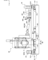
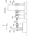
- FIG. 1 is a left side view of a flat tire testing device according to one embodiment of the present invention
- FIG. 1 is a plan view of a flat-type tire testing device according to one embodiment of the present invention
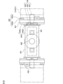
- FIG. 1 is a rear view of a flat-type tire testing device according to one embodiment of the present invention
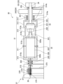
- FIG. 1 is an enlarged view (left side view) of a flat-type tire testing device according to an embodiment of the present invention
- FIG. 1 is an enlarged view (plan view) of a flat-type tire testing device according to an embodiment of the present invention
- FIG. It is the figure which showed arrangement
- It is a sectional view of a guide mechanism (A type).
- It is a sectional view of a guide mechanism (B type).
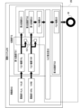
- FIG. 1 is a block diagram showing a schematic logical configuration of a drive system;
- FIG. 1 is a diagram showing a schematic mechanical configuration of main parts of a drive system;
- FIG. It is the figure which showed the schematic structure of a drive part and a drive pulley part.
- FIG. 16 is a cross-sectional view taken along line AA of FIG.
- FIG. 15 It is a sectional view of a 2nd driven part. It is a sectional view of a torque giving part.
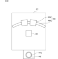
- 4 is a diagram showing a schematic structure of an alignment section 40;
- FIG. FIG. 21 is a view taken along line BB of FIG. 20;
- FIG. 21 is a CC arrow view of FIG. 20;
- FIG. 21 is a view taken along line DD of FIG. 20;
- FIG. 21 is a view taken along line EE of FIG. 20; It is the figure which showed the schematic structure of a spindle part.
- It is a cross-sectional view of a road surface part.
- FIG. 10 is a cross-sectional view of a modification of the road surface portion; It is a top view near the load detection part of a road surface part.
- FIG. 4 is a plan view showing a state in which a movable portion of the load detection section is removed;
- FIG. 20 is an enlarged view of area E in FIG. 19;
- 1 is a block diagram showing a schematic configuration of a control system of a tire testing system;
- FIG. 1 is a block diagram showing a schematic configuration of a control system of a flat-type tire testing device;
- FIG. 1 is a plan view of a drum-type tire testing device according to an embodiment of the present invention;
- FIG. 1 is a front view of a drum-type tire testing device according to an embodiment of the present invention
- FIG. 1 is a right side view of a drum-type tire testing device according to an embodiment of the present invention
- FIG. 1 is a left side view of a drum-type tire testing device according to an embodiment of the present invention
- FIG. 1 is a block diagram showing a schematic configuration of a control system of a drum-type tire testing device
- FIG. It is an external view of the simulated road surface unit of the drum-type tire testing device.
- FIG. 4 is a cross-sectional view of a simulated road surface unit of the drum-type tire testing device; It is a longitudinal cross-sectional view of a torque generating part.
- FIG. 4 is a side view of the camber adjustment mechanism; 4 is a flow chart showing a procedure for obtaining ⁇ -S characteristics; 4 is a flow chart showing a procedure for obtaining ⁇ -S characteristics;
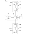
- a tire testing system 1 includes a flat type tire testing device 1000 that performs testing with a test tire T grounded on a flat road surface 63a, and a rotating drum 2022. Equipped with a drum-type tire testing device 2000 that performs a test in a state where the test tire T is grounded on the formed cylindrical surface 2023b. This is a test system capable of evaluating the performance of a test tire T close to the case of actually running on a road surface over a wide speed range.
- FIG. 1-3 are, in order, a left side view, a plan view and a rear view of the flat tire testing device 1000.
- FIG. 4 and 5 are a left side view and a plan view, respectively, omitting an intermediate portion in the longitudinal direction (X-axis direction) of the flat tire testing device 1000. As shown in FIG.
- the direction from right to left is defined as the X-axis direction
- the direction from top to bottom is defined as the Y-axis direction
- the direction from back to front perpendicular to the paper surface is defined as the Z-axis direction.
- the X-axis direction and the Y-axis direction are horizontal directions perpendicular to each other, and the Z-axis direction is a vertical direction. That is, in the description of the flat-type tire testing apparatus 1000, unless otherwise specified, the front-rear, left-right, and up-down directions are defined as the directions when the carriage 20 faces the running direction (X-axis positive direction). do.
- the positive direction of the X-axis is forward, the negative direction of the X-axis is backward, the positive direction of the Y-axis is left, the negative direction of the Y-axis is right, the positive direction of the Z-axis is upward, and the negative direction of the Z-axis is downward.
- a flat tire testing apparatus 1000 includes a track portion 10 and a road surface portion 60 elongated in the X-axis direction, and a carriage 20 capable of traveling on the track portion 10 in the X-axis direction.
- the road surface portion 60 is mounted on the left portion of the base frame 11 (hereinafter abbreviated as “base 11”) of the track portion 10 .
- a road surface 63 a on which the test tire T mounted on the carriage 20 is grounded is provided on the upper surface of the road surface portion 60 .
- the road surface portion 60 is detachably attached to the base 11 of the track portion 10 so that the road surface portion 60 can be replaced according to test conditions.
- the base 11 of the track portion 10 and the frame 61 of the road surface portion 60 may be integrated by, for example, welding.
- the road surface portion 60 may be directly installed on the foundation F ( FIG. 3 ) to completely separate the road surface portion 60 from the track portion 10 .
- a pair of wheel stops 13 are provided at the front end of the track section 10 adjacent to drive sections 14LB and 14RB, which will be described later.
- the wheel stop 13 is a device that collides with the carriage 20 to forcibly stop the carriage 20 when the carriage 20 overruns.
- Each bollard 13 is provided with a pair of hydraulic shock absorbers 131 that absorb the shock generated when colliding with the carriage 20 .
- a test wheel W (that is, a wheel rim Wr on which a test tire T is mounted) is attached to the carriage 20 .
- the carriage 20 runs with the test wheel W in contact with the road surface 63a, and the test wheel W rolls on the road surface 63a.
- the track section 10 includes a plurality (three in the illustrated embodiment) of guide mechanisms 12A, 12B and 12C for guiding the movement of the carriage 20 in the X-axis direction.
- the guide mechanisms 12A, 12B, and 12C are installed at the left end, width direction (that is, Y-axis direction) central portion, and right end of the track portion 10, respectively.
- FIG. 6 is a left side view of the guide mechanism 12A.
- 7 and 8 are cross-sectional views of guide mechanisms 12A and 12B, respectively. Since the guide mechanism 12C is bilaterally symmetrical to the guide mechanism 12A, a detailed description of the guide mechanism 12C is omitted.
- Each of the guide mechanisms 12A, 12B, and 12C includes one rail 121 forming a track extending in the X-axis direction, and one or more (two in the illustrated embodiment) running portions 122A capable of running on the rail 121. (FIG. 7), 122B (FIG. 8), or 122C (not shown, configured symmetrically with the running portion 122A of the guide mechanism 12A).
- FIG. 6 for the running portion 122A, one of the two running portions 122A, 122B, and 122C is attached to the front end (the left end in FIG. 6) of the bottom surface of the carriage 20, and the other is attached to the rear end. (right end in FIG. 6).
- the rail 121 is laid on the base 11 of the track section 10. As shown in FIGS. Further, the running portions 122A, 122B and 122C are attached to the lower surface of the main frame 21 of the carriage 20. As shown in FIG.
- the rail 121 is, for example, a flat bottom rail having a head portion 121h, a bottom portion 121f wider than the head portion 121h, and a narrow abdomen 121w connecting the head portion 121h and the bottom portion 121f.
- the rail 121 of this embodiment is, for example, a heat-treated rail conforming to Japanese Industrial Standards JIS E 1120:2007 (for example, a heat-treated rail 50N-HH340) with additional processing.
- a heat-treated rail is a railway rail whose head is heat-treated to improve wear resistance.
- the traveling portion 122A of the guide mechanism 12A includes a frame 123 long in the X-axis direction attached to the lower surface of the main frame 21 of the carriage 20, and a plurality of roller units 128A attached to the frame 123.
- Roller unit 128A comprises three rods 124a, 124b and 124c attached to frame 123 and three roller assemblies 125a, 125b and 125c attached to each rod 124a, 124b and 124c respectively.
- the three roller assemblies 125a, 125b and 125c of each roller unit 128A are arranged at the same position in the X-axis direction.
- the plurality of roller units 128A are arranged at predetermined intervals in the X-axis direction.
- Roller assemblies 125b and 125c have the same configuration as roller assembly 125a (although in this embodiment the invention is not limited to this configuration, roller assembly 125c is a roller assembly). The size is different from that of the product 125a.) Therefore, the roller assembly 125a will be described as a representative of these, and duplicate descriptions of the roller assemblies 125b and 125c will be omitted.
- the roller assembly 125a includes a roller 126a that rolls on the rail 121 and a pair of bearings 127a that rotatably support the roller 126a.
- the bearing 127a is a rolling bearing, and a ball bearing is used in the illustrated embodiment.
- the outer peripheral surface 126ap of the roller 126a is formed in a cylindrical surface shape, but the curved surface (for example, it may be a spherical surface centered on the center point 126ag of the roller 126a.
- the bearing 127a of the roller assembly 125a is, for example, a single row radial bearing.
- the bearing 127a includes an inner ring 127a1 fitted with the rod 124a, an outer ring 127a3 fitted with the inner peripheral surface of the roller 126a, and a plurality of balls 127a2 interposed between the inner ring 127a1 and the outer ring 127a3.
- the ball 127a2 rolls on a circular orbit determined by a pair of annular grooves respectively formed on the outer peripheral surface of the inner ring 127a1 and the inner peripheral surface of the outer ring 127a3.
- the roller assembly 125a is arranged so that the outer peripheral surface 126ap contacts the head top surface (top surface) 121a of the rail 121 and rolls on the head top surface 121a as the carriage 20 travels.
- the roller assembly 125b is arranged so that the outer peripheral surface 126bp contacts one of the head lower surfaces 121b of the rail 121 and rolls on the head lower surface 121b.
- the roller assembly 125c is arranged so that the outer peripheral surface 126cp contacts one of the head side surfaces 121c of the rail 121 and rolls on the head side surface 121c.
- the top surface 121a, the bottom surface 121b, and the side surface 121c of the head which are in contact with the roller assemblies 125a, 125b, and 125c, respectively, are flattened, and the surface accuracy such as flatness and parallelism is improved. Additional processing (for example, grinding, polishing, etc.) is performed to enhance the quality.
- the guide mechanisms 12A and 12C attached to the left and right ends of the carriage 20 are bilaterally symmetrical.
- the guide mechanism 12C is the same as the guide mechanism 12A, but is arranged in the left-right opposite direction (that is, rotated 180 degrees around the Z-axis).
- the traveling portion 122B of the guide mechanism 12B includes a frame 123 attached to the lower surface of the main frame 21 of the carriage 20 and a plurality of roller units 128B attached to the frame 123.
- Roller unit 128B includes two rods 124a and 124b and two roller assemblies 125a and 125b. Further, the rod 124b and the roller assembly 125b are arranged on the left side of the rail 121 in the traveling portion 122A of the guide mechanism 12A described above, while they are arranged on the right side of the rail 121 in the traveling portion 122B of the guide mechanism 12B. ing.
- the traveling portion 122B of the guide mechanism 12B is configured by omitting the roller assembly 125c and the rod 124c from the traveling portion 122A of the guide mechanism 12A described above, and arranging the left and right opposite directions.
- the traveling portion 122B of the guide mechanism 12B may include the roller assembly 125c and the rod 124c.
- rod 124c and roller assembly 125c are positioned, for example, on the right side of rail 121 (ie, on the same side of rail 121 as rod 124b and roller assembly 125b).
- the carriage 20 is prevented from moving to the right (Y-axis negative direction) with respect to the rail 121 by the roller assemblies 125b and 125c of the guide mechanism 12A arranged on the left side of the rail 121. Further, the carriage 20 is moved to the left (Y-axis positive direction) with respect to the rail 121 by the roller assembly 125b of the guide mechanism 12B and the roller assemblies 125b and 125c of the guide mechanism 12C, which are arranged on the right side of the rail 121. is blocked. Therefore, the carriage 20 is prevented from moving to both sides in the Y-axis direction with respect to the rails 121 .
- the running portion 122B (Fig. 8) is arranged in the left-right opposite direction to the running portion 122A (Fig. 7), but the running portion 122B may be arranged in the same left-right direction as the running portion 122A.
- the running portion 122C and the running portion 122A may be arranged in the same direction on the left and right.
- any two of the running portion 122A, the running portion 122B, and the running portion 122C are arranged in opposite left and right directions (that is, the roller assemblies 125b and 125c are arranged in opposite left and right directions with respect to the rail 121).
- two of the traveling portions 122A, 122B and 122C which are arranged in opposite directions to each other, are provided with a rod 124 and a roller assembly 125c. I hope you are.
- At least one of the traveling parts 122A, 122B and 122C should be provided with a roller assembly 125b and a rod 124b.
- the roller assembly 125b can be used instead of the roller assembly 125c.
- the rail 121 of the guide mechanism 12 may be formed by connecting a plurality of short rail members.
- the joint 121j of the rail 121 is not perpendicular to the length direction (X-axis direction) of the rail 121, but is oblique in plan view (that is, the joint 121j is in the ZX plane). It may be formed at a certain angle ⁇ [however, 0 ⁇ /2]).
- a typical value for the angle ⁇ is ⁇ /4, for example.
- the strain of the rail 121 is released by sliding the rail members at the joint 121j, thereby preventing the rail 121 from bending. .
- the head side surface 121c of the rail 121 in front of the joint 121j forms an obtuse angle ( ⁇ - ⁇ ) with the joint 121j (that is, the left side in the guide mechanism 12A, and the guide mechanism Roller assemblies 125b and 125c (Fig. 9) are located on the right side in 12B and 12C).
- roller assemblies 125b and 125c By arranging roller assemblies 125b and 125c in this manner, roller assemblies 125b and 125c will remain in contact with seam 121j even if seam 121j of rail 121 is misaligned (i.e., the rail members slide along seam 121j). colliding with the sharp edge 121e of , causing a large impact or damage.
- the end faces of the two rail members to be connected may be brought into contact with each other, or they may be butted against each other in a non-contact manner with a predetermined gap provided between the end faces.
- the end faces of the two rail members to be connected are simply butted against each other at the joint 121j of the rail 121 and are not joined, but the rail members are joined at the joint 121j by welding, brazing, or the like. May be joined.
- a guideway type circulating linear bearing (so-called linear guide) can also be used.
- a ball circulating linear bearing has an oval raceway formed by connecting adjacent ends of two parallel linear raceways with semicircular raceways.
- the bearings 127a to 127c used in the guide mechanisms 12A, 12B and 12C of the present embodiment since the rolling elements always run on a circular orbit with a constant curvature, the centrifugal force acting on the rolling elements suddenly fluctuates (that is, impact load) does not occur. Therefore, even if the rollers 126a-126c are rotated at a high circumferential speed exceeding, for example, 60 km/h, the life of the bearings 127a-127c is not significantly shortened or damaged. Therefore, by constructing the guide mechanisms 12A to 12C using rolling bearings having circular orbits in which the orbits of the rolling elements have a constant curvature, the carriage 20 can travel at high speeds (for example, traveling at a speed of 10 km/h or more). becomes possible.
- the flat-type tire testing apparatus 1000 of this embodiment employs the above-described guide mechanisms 12A, 12B, and 12C, so that the carriage 20 can travel at a speed exceeding 85 km/h.
- the flat tire testing apparatus 1000 includes a drive system DS that drives the carriage 20 and test wheels W.
- FIG. 10 is a block diagram showing a schematic logical configuration of the drive system DS.
- FIG. 11 is a diagram showing a schematic mechanical configuration of main parts of the drive system DS.
- arrows represent transmission paths of mechanical power (hereinafter simply referred to as "power").
- the drive system DS includes an actuating portion AS that generates power, and a transmission portion TS that transmits the motive power generated by the actuating portion AS to the carriage 20 and the test wheel W that are to be driven.
- the drive system DS constitutes a power circulation system together with the carriage 20 , the test wheel W and the road surface portion 60 .
- the driving unit AS includes two pairs of left and right driving units 14 (first driving means) attached to the track portion 10, and a torque applying device 30 (second driving means) (hereinafter referred to as a torque applying unit) attached to the carriage 20. , referred to as a “torque generating portion”).
- the drive unit 14 is mainly used to control the running speed of the carriage 20 and the rotational speed of the test wheel W, and the torque generator 30 is mainly used to control the torque applied to the test wheel W.
- the transmission portion TS includes a first transmission portion TS1 that transmits the power generated by the drive portion 14 to the carriage 20, and a second transmission portion that extracts part of the power transmitted by the first transmission portion TS1 and transmits it to the torque generation portion 30.
- two pairs of drive portions 14 are arranged near four corners on the base 11 of the track portion 10. is installed on the The drive portions 14LA and 14RA are arranged at the rear end portion of the track portion 10, and the drive portions 14LB and 14RB are arranged at the front end portion of the track portion 10. As shown in FIG.
- the right drive units 14RA and 14RB function as carriage drive means for driving the carriage 20 to travel, and also serve as a test wheel for rotationally driving the test wheel W at a rotation speed corresponding to the travel speed of the carriage 20. It also has a function as a drive means (rotational speed imparting means).
- the left drive units 14LA and 14LB function as carriage drive means.
- the first transmission part TS1 includes a pair of belt mechanisms 15 (15L, 15R) and driven parts (first driven part 22 and second driven part 23).
- the left belt mechanism 15L is driven by a pair of left drive units 14LA and 14LB
- the right belt mechanism 15R is driven by a pair of right drive units 14RA and 14RB.
- the first driven portion 22 and the second driven portion 23 are attached to the main frame 21 of the carriage 20 .
- the first driven portion 22 is connected to the right belt mechanism 15R
- the second driven portion 23 is connected to the left belt mechanism 15L.
- FIG. 12-14 are diagrams showing the schematic structures of the driving section 14 and the driving pulley section 150 of the belt mechanism 15.
- FIG. 15 and 16 are a plan view and a left side view of the first driven portion 22.
- FIG. 17 is a cross-sectional view taken along line AA of FIG. 15.
- FIG. 18 is a cross-sectional view showing a schematic structure of the second driven portion 23. As shown in FIG.
- Each belt mechanism 15 (15L, 15R) includes a pair of drive pulley portions 150, belts 151 (151L, 151R), and three driven pulleys 155A, 155C and 156 held by the first driven portion 22 (FIG. 16). or three driven pulleys 155A, 155B and 155C (FIG. 18) held by the second driven portion 23 and a pair of belt clamps 157 (FIGS. 5).
- the drive pulley 150 is mounted on the frame 14a of the corresponding drive 14 and connected to the drive 14 (FIG. 12).
- the drive pulley section 150 also includes a tension adjustment section 16 that automatically adjusts the tension of the belt 151 .
- the belt 151R is wound around the drive pulleys 152 (152A, 152B) of the pair of drive pulley parts 150 (150A, 150B) and the three driven pulleys 155A, 156 and 155C of the first driven part 22.
- the belt 151L is wound around the driving pulleys 152 (152A, 152B) of the pair of driving pulley portions 150 (150A, 150B) and the three driven pulleys 155A, 155B and 155C of the second driven portion 23.
- the driving section 14 includes a pair of motors 141 (141A, 141B) (first motor) and a pair of belt mechanisms 142 (142A, 142B).
- the motor 141 has, for example, a moment of inertia of the rotating part of 0.01 kg ⁇ m 2 or less (more preferably 0.008 kg ⁇ m 2 or less) and a rated output of 3 kW to 60 kW (more practically, 7 kW to 37 kW). ) is an ultra-low inertia high-output AC servo motor.
- the use of such an ultra-low inertia and high power motor 141 allows the carriage 20 to be accelerated over a short distance (eg 20-50m) to the maximum speed of the test tire T (eg 240km). .
- the motor 141 may be a motor whose rotating part has a normal moment of inertia.
- the motor 141 may be another type of electric motor capable of speed control, such as a so-called inverter motor that uses an inverter for drive control.
- the pair of motors 141A and 141B are arranged in the front-rear direction (X-axis direction) with the shaft 141b facing left and right (Y-axis direction). Also, the pair of motors 141A and 141B are arranged with their shafts 141b facing left and right reversed. That is, the shaft 141b of one motor 141A protrudes to the left (Y-axis positive direction), and the shaft 141b of the other motor 141B protrudes to the right (Y-axis negative direction).
- a belt mechanism 142A that transmits the power of the motor 141A is arranged on the left side of the driving section 14, and a belt mechanism 142B that transmits the power of the motor 141B is arranged on the left side of the driving section 14.
- the belt mechanism 142 includes a drive pulley 142a attached to the shaft 141b of the motor 141, a driven pulley 142c, and a belt 142b wound around the drive pulley 142a and the driven pulley 142c.
- the belt 142b is, for example, a toothed belt having the same configuration as the belt 151 described later.
- the type of belt 142 b may be different from that of belt 151 .
- the belt mechanism 142 has a reduction ratio greater than 1 because the driven pulley 142c has a larger pitch diameter than the drive pulley 142a (that is, has more teeth). Therefore, the rotation output from the motor 141 is decelerated by the belt mechanism 142 .
- the speed reduction ratio of the belt mechanism 142 may be 1 or less.
- a speed reducer may be provided in the drive section 14 .
- the shaft 153 of the belt mechanism 15 is directly connected to the shaft 141b of the motor 141 without providing the belt mechanism 142 or the speed reducer (for example, the shaft 141b of the motor 141A is connected to one end of the shaft 153 and the shaft 141b of the motor 141A is connected to the other end).
- the shaft 141b of the motor 141B may be coupled).
- a driving pulley portion 150 of the belt mechanism 15 is arranged adjacent to the left side of the driving portion 14 .
- the drive pulley portion 150 includes two or more (eg, three) bearing portions 154 , a shaft 153 rotatably supported by the plurality of bearing portions 154 , and a drive pulley 152 attached to the shaft 153 .
- the driven pulleys 142c of the pair of belt mechanisms 142A and 142B are also attached to the shaft 153, and the output of the driving section 14 is transmitted to the belt 151 wound around the driving pulley 152 via the shaft 153 and the driving pulley 152. . That is, the power output from the pair of motors 141A and 141B is transmitted to the shaft 153 by the pair of belt mechanisms 142A and 142B, respectively, and combined at the shaft 153 .
- the drive unit 14 includes a pair of motors 141A and 141B and a pair of belt mechanisms 142A and 142B, but may include a single or three or more multiple motors 141 and belt mechanisms 142. may
- the tension adjusting section 16 of this embodiment includes a first adjusting section 16A and a second adjusting section 16B.
- the first adjuster 16A is a mechanism that adjusts the tension of the belt 151 by pushing the lower portion of the loop of the belt 151 into the inside of the loop.
- the second adjuster 16B is a mechanism that adjusts the tension of the belt 151 by pushing the upper portion of the loop of the belt 151 into the inside of the loop.
- the first adjusting portion 16A includes a bearing portion 161 attached to the frame 14a of the drive portion 14, an arm 162 supported by the bearing portion 161 so as to be swingable about the Y-axis, and one end portion of the arm 162 rotatably supported. It has a supported dancer roll 164 and a linear actuator 166 (eg, an air cylinder) that drives the other end of the arm 162 up and down.
- a linear actuator 166 eg, an air cylinder
- the arm 162 is formed in a zigzag shape by bending in opposite directions at two points in the length direction. One end of arm 162 is bent at about 90 degrees to prevent interference with belt 151, and the other end of arm 162 is bent at an obtuse angle in accordance with the range of motion of linear actuator 166 and dancer roll 164.
- Pivots 162a and 162b extending to both sides in the Y-axis direction are provided at the rear end portion and the central portion (that is, the bent portion on the other end side) of the arm 162, respectively.
- the pivot 162 a is rotatably supported by the bearing portion 161 .
- a bearing portion 162c that rotatably supports a shaft 164a of the dancer roll 164 is provided at the tip of the arm 162. As shown in FIG.
- the linear actuator 166 includes a main body 166a attached to the frame 14a of the drive section 14, a rod 166b projecting downward from the main body 166a, and a bearing 166c provided at the tip of the rod.
- Bearing 166c forms a joint with pivot 162b by which rod 166b and arm 162 are rotatably connected about pivot 162b.
- the operation of the linear actuator 166 is controlled by controlling the air pressure supplied to the linear actuator 166 with a solenoid valve 166d (Fig. 36).
- Electromagnetic valve 166d is communicably connected to control unit 1070 and its operation is controlled by control unit 1070 .
- a proportional control valve such as an electropneumatic regulator capable of controlling the pressure of pressurized fluid such as compressed air supplied to the linear actuator 166 can be used as the solenoid valve 166d.
- the linear actuator 166 When the linear actuator 166 operates and the rod 166b advances and retreats, the arm 162 connected to the rod 166b at the other end swings about the pivot 162a. 164 advances and retreats toward belt 151 .
- the rod 166b When the rod 166b is extended, the lower portion of the loop of the belt 151 is pushed inward by the dancer roll 164 and the tension of the belt 151 is increased. That is, the tension of the belt 151 can be adjusted according to the amount of actuation of the linear actuator 166 . Further, the tension of the belt 151 can be kept constant by supplying pressurized fluid of constant pressure to the linear actuator 166 by means of an electropneumatic regulator.
- the second adjusting section 16B includes a frame 169 fixed to the frame 14a of the driving section 14 and a dancer roll 167 rotatably supported by the frame 169.
- the frame 169 has a pair of flat plate portions 169f perpendicular to the rotation axis of the dancer roll 167 (that is, the Y-axis direction), and is formed in an inverted U shape when viewed from the X-axis direction.
- a vertically extending slot 169a is formed in each flat plate portion 169f.
- the frame 169 has a support shaft 168b that supports the dancer roll 167. Both ends of the support shaft 168b are fitted into slots 169a of the respective flat plate portions 169f, and are guided by the slots 169a to be held movably up and down. ing.
- a dancer roll 167 is attached to the central portion of the support shaft 168b via a bearing 168c. Dancer roll 167 rests on the upper portion of the loop of belt 151 .
- Each flat plate portion 169f of the frame 169 is formed with a screw hole 169b extending from the upper end surface to the groove hole 169a, and a long bolt 168a is fitted into the screw hole 169b.
- the tip of the long bolt 168a is in contact with the end of the support shaft 168b, and when the long bolt 168a is screwed in, the support shaft 168b and the dancer roll 167 are pushed downward, and the dancer roll 167 moves the upper part of the loop of the belt 151. are pushed inward and the tension of the belt 151 is increased. That is, the tension of the belt 151 can be adjusted according to the screwing amount of the long bolt 168a.
- a tension meter 163 (FIG. 36) for detecting the tension of the belt 151 is provided in the tension adjustment unit 16, for example, and based on the detection result of the tension meter 163 , the drive of the linear actuator 166 may be controlled so that a predetermined tension is maintained.
- linear actuator 166 is not limited to an air cylinder, and a mechanism combining a rotary motor such as a hydraulic cylinder, a linear motor, a servomotor, and a motion converter such as a ball screw can be used.
- the belt 151 is a toothed belt having a steel wire core.
- the belt 151 may have core wires made of so-called super fibers such as carbon fibers, aramid fibers, and ultra-high molecular weight polyethylene fibers.
- a motor with a relatively low output is used to drive the carriage 20 at high acceleration (or a high driving force/braking force on the test wheel W). can be given), and the size of the flat tire testing device 1000 can be reduced.
- the use of a lightweight belt 151 having a core wire made of so-called super fiber improves the performance of the flat tire testing device 1000 (specifically, acceleration performance improvement).
- each belt 151 is fixed to the main frame 21 of the carriage 20 by belt clamps 157, respectively. Thereby, each belt 151 forms a loop via the carriage 20 .
- each belt mechanism 15 operates, the carriage 20 is pulled by each belt 151 and travels in the X-axis direction.
- the belt 151 is fixed to the carriage 20 by a belt clamp 157 at the lower portion of the loop of the belt 151, and the belt 151 and the first driven portion 22 or the second driven portion 23 are connected at the upper portion of the loop. ing.
- the belt 151 may be fixed to the carriage 20 above the loop.
- the pair of drive pulleys 152 (152A, 152B) of the belt mechanism 15 are arranged with an area in which the carriage 20 can run, and are held on the base 11 (that is, the center of gravity).
- fixed pulley position fixed with respect to base 11
- the driven pulleys 155 (155A, 155B, 155C) and 156 held by the first driven portion 22 or the second driven portion 23 are movable pulleys that can move in the X-axis direction together with the carriage 20 .
- the pair of drive units 14LA and 14LB [14RA and 14RB] are driven in phase. Further, the left drive units 14LA and 14LB and the right drive units 14RA and 14RB are arranged in the left-right reversed direction and are driven in opposite phases to each other.
- the driving pulley 152 (Fig. 13) and the driven pulley 155 (Figs. 16 and 18) have the same effective diameter (that is, the pitch diameter) or the number of teeth.
- the pitch diameter or the number of teeth of the driven pulley 156 (FIG. 16) held by the first driven portion 22 is larger (for example, doubled) than the drive pulley 152 and the driven pulley 155 .
- the carriage 20 includes a main frame 21, a first driven portion 22, a second driven portion 23, a belt mechanism 24, a belt mechanism 25, a transmission shaft portion 26, a braking device 27, a braking device 28, a torque It has a generating section 30, an alignment section 40 and a spindle section 50 (axle section).
- the first driven portion 22 and the belt mechanism 24 constitute a second transmission portion TS2.
- the belt mechanism 25, the transmission shaft portion 26 and the spindle portion 50 constitute a third transmission portion TS3.
- the spindle section 50 has a spindle 52 that is rotatably supported.
- the spindle 52 is a shaft (i.e., a member corresponding to an axle) to which the test wheel W is coaxially attached to one end (i.e., so as to share the center line). Together with 52, the test wheel W is rotationally driven.
- the alignment section 40 is a mechanism section capable of adjusting the wheel alignment (alignment adjustment) of the test wheel W by changing the orientation of the spindle section 50 .
- the first driven part 22 includes a main body part 221, a bearing part 222, a bearing part 223, a shaft 224, a drive gear 225, a shaft 226 and a driven gear 227.
- the main body 221 includes two rods 221b extending in the Y-axis direction and a pair of bearings 221c having inner rings fitted to the rods 221b.
- the driven pulleys 155A and 155C of the belt mechanism 15R are fitted with the outer rings of the bearings 221c. With this configuration, the driven pulleys 155A and 155C of the belt mechanism 15R are rotatably supported by the body portion 221. As shown in FIG.
- the body portion 221 has a bearing 221a.
- the bearing portion 222 includes a pair of bearings 222a and 222b arranged vertically.
- the bearing portion 223 includes a pair of bearings 223a and 223b arranged vertically.
- the shaft 224 is rotatably supported by a bearing 221a at one end in the length direction, a bearing 223a at the other end, and a bearing 222a at an intermediate portion.
- a driven pulley 156 and a drive gear 225 of the belt mechanism 15R are attached to the shaft 224 .
- the shaft 226 is shorter than the shaft 224 and is rotatably supported at one end in the length direction by a bearing 222b and at the other end by a bearing 223b.
- a driven gear 227 meshing with the driving gear 225 and a driving pulley 241 of the belt mechanism 24 are attached to the shaft 226 .
- the driven pulley 156 (belt mechanism 15R) and the drive pulley 241 (belt mechanism 24) are connected via the first driven portion 22.
- a portion of the power transmitted by belt mechanism 15R is transmitted to shaft 224 via driven pulley 156, then to shaft 226 via drive gear 225 and driven gear 227, and further to drive pulley 241. is transmitted to the belt mechanism 24.
- the power transmitted to the belt mechanism 24 is used to drive the test wheel W.
- the first driven portion 22 on the right side and the driven pulley 156 (and the driven pulleys 155A and 155C) rotatably supported by the first driven portion 22 extract part of the power from the belt mechanism 15R, It has the function of feeding the mechanism 24 .
- the rest of the power transmitted by the belt mechanism 15R is transmitted to the main frame 21 of the carriage 20 to which the belt 151 is fixed by the belt clamp 157 and used to drive the carriage 20.
- the right belt mechanism 15R constitutes part of means for driving the carriage 20 (carriage driving means) and also constitutes part of means for driving the test wheel W (test wheel driving means).
- the right belt mechanism 15R together with the right first driven portion 22, converts the power generated by the drive portions 14RA and 14RB into the power used to drive the carriage 20 and the power used to drive the test wheel W. It functions as means for distribution (power distribution means).
- the belt mechanism 15R of this embodiment has a reduction ratio greater than 1 because the driven pulley 156 on the output side has a larger pitch diameter than the drive pulley 152 on the input side.
- the present invention is not limited to this configuration, and the pitch diameter of the driven pulley 156 may be less than or equal to the pitch diameter of the drive pulley 152, and the reduction ratio of the belt mechanism 15R may be less than or equal to 1.
- the first driven part reverses the direction of rotation of the power by including the driving gear 225 and the driven gear 227 .
- the second driven portion 23 (body portion 231) includes three rods 231b extending in the Y-axis direction and three bearings 231c having inner rings fitted to the respective rods 231b.
- the three rods 231b are arranged at regular intervals in the X-axis direction.
- the central rod 231b is positioned higher than the remaining two rods 231b, but all rods 231b may be positioned at the same height.
- Three driven pulleys 155 (driven pulleys 155A, 155B and 155C in order from the front) of the belt mechanism 15L are fitted to the outer ring of each bearing 231c. With this configuration, the driven pulleys 155A, 155B and 155C of the belt mechanism 15L are rotatably supported by the second driven portion 23. As shown in FIG.
- the belt 151 of the belt mechanism 15 is folded back by drive pulleys 152A and 152B to be divided into an upper portion 151a and a lower portion 151b.
- the upper portion 151a and the lower portion 151b are stretched in the running direction of the carriage 20 and driven in opposite directions.
- the lower portion 151b of the belt 151 fixed to the carriage 20 is driven together with the carriage 20 in the carriage running direction, and the upper portion 151a is driven in the opposite direction to the carriage 20 and the lower portion 151b. be done.
- Driven pulleys 155 and 156 (FIGS. 16 and 18) attached to the carriage 20 are wound around an upper portion 151a of a belt 151 running in the opposite direction to the carriage 20 and driven by the upper portion 151a. be.
- part of the power transmitted by the right belt mechanism 15R is transmitted to the torque generating section 30 by the second transmission section TS2, and is further transmitted to the test wheel by the third transmission section TS3. W and used to drive the test wheel W.
- the second transmission section TS2 includes the first driven section 22 and the belt mechanism 24, and the third transmission section TS3 includes the belt mechanism 25, the transmission shaft section 26 and the spindle section 50.
- the remaining portion of the power transmitted by the right belt mechanism 15R is transmitted to the main frame 21 of the carriage 20 to which the leading edge of the belt 151 is fixed by the belt clamp 157 and used to drive the carriage 20. be done. Both the carriage 20 and the test wheel W can be driven by the belt 151 by the belt mechanism 15R and the first driven portion 22 configured as described above.
- the second driven portion 23 on the left side has a configuration (specifically, a bearing portion 222, 223, shafts 224, 226, drive gear 225, and driven gear 227). Although the second driven portion 23 on the left side is not an essential component, by providing the second driven portion 23 on the left side, the forces that the carriage 20 receives from the left and right belt mechanisms 15L and 15R are balanced, and the carriage 20 travels. stabilizes.
- this embodiment employs a configuration in which the carriage 20 and the test wheel W are driven using the power transmitted by the common power transmission device (that is, the belt mechanism 15R).
- the test wheel W can always be rotationally driven at a peripheral speed (or rotation speed) corresponding to the running speed of the carriage 20 .
- the test wheel in order to reduce the amount of operation (that is, power consumption) of the torque generating section 30, the test wheel is driven at substantially the same peripheral speed as the running speed of the carriage 20 when the torque generating section 30 is not operating.
- W is configured to be rotationally driven.
- the belt mechanism 24 includes a driving pulley 241 attached to the shaft 226 (FIG. 17) of the first driven portion 22 described above, and a driven pulley 242 attached to the shaft portion 314 (FIG. 19) of the torque generating portion 30 described later. , a belt 243 wound around a driving pulley 241 and a driven pulley 242 .
- the belt 243 is, for example, a toothed belt having the same configuration as the belt 151 described above.
- the type of belt 243 may be different from belt 151 .
- FIG. 19 is a diagram showing a schematic structure of the torque generating section 30.
- the torque generator 30 generates torque to be applied to the test wheel W, adds this torque to the rotational motion transmitted by the belt mechanism 24, and outputs the torque. In other words, the torque generator 30 applies torque to the test wheel W by changing the phase of the rotational motion transmitted by the belt mechanism 24 (that is, the driving force or braking force).
- the torque generating section 30 functions as a second driving means for generating power for driving the test wheel W, and the power generated by the motor 141 (first motor) of the driving section 14 (first driving means) and the torque generating section It also functions as a power coupling means that couples the power generated by the motor 32 (second motor) built in 30 .
- the torque generating section 30 By incorporating the torque generating section 30 into the drive system DS, the power source (drive sections 14RA, 14RB) for controlling the rotation speed of the test wheel W and the power source (motor 32 described later) for controlling the torque. Roles can be shared. As a result, it becomes possible to use a power source with a smaller capacity, and to control the rotational speed and torque applied to the test wheel W with higher accuracy. In addition, by incorporating the torque generating section 30 into the carriage 20, the load applied to the belt mechanism 15R is reduced. Allows the use of low members.
- the torque generating unit 30 includes a rotating frame 31, a motor 32 (second motor) mounted in the rotating frame 31, a speed reducer 33 and a shaft 34, three bearings 351 that rotatably support the rotating frame 31, 352 and 353 , a slip ring portion 37 , and a rotary encoder 38 for detecting the number of rotations of the rotating frame 31 .
- the motor 32 has a moment of inertia of the rotating part of 0.01 kg ⁇ m 2 or less (more preferably 0.008 kg ⁇ m 2 or less) and a rated output of 3 kW to 60 kW (more practical , 7 kW to 37 kW) are used.
- the rotating frame 31 includes a substantially cylindrical first cylindrical portion 311 (motor accommodating portion), a second cylindrical portion 312 (connecting cylinder), and a third cylindrical portion 313 having a large diameter, and a diameter smaller than that of the first cylindrical portion 311. It has substantially cylindrical shafts 314 and 315 .
- a shaft portion 314 is coaxially coupled to one end (right end in FIG. 19) of the first cylindrical portion 311 via a second cylindrical portion 312 and a third cylindrical portion 313 .
- a shaft portion 315 is coaxially coupled to the other end portion (the left end portion in FIG. 19) of the first cylindrical portion 311 .
- the shaft portion 314 is rotatably supported by bearing portions 351 and 353, and the shaft portion 315 is rotatably supported by a bearing portion 352, respectively.
- a motor 32 is accommodated in the hollow portion of the first cylindrical portion 311 .
- the motor 32 has a shaft 321 arranged coaxially with the rotating frame 31 , and a motor case 320 (that is, a stator) is fixed to the first cylindrical portion 311 with a plurality of stud bolts 323 .
- a reduction gear 33 is arranged in the hollow portions of the second tubular portion 312 and the third tubular portion 313 .
- the input shaft 332 of the speed reducer 33 is connected to the shaft 321 of the motor 32
- the output shaft 333 is connected to the shaft 34 .
- a flange 312a is formed at one end (the right end in FIG. 19) of the second tubular portion 312 and protrudes outward.
- the other end (the left end in FIG. 19) of the second tubular portion 312 is formed with a flange 312b protruding to the outer periphery and an inner flange 312c protruding to the inner periphery.
- the flange 320a of the motor 32 is fixed to the inner flange 312c of the second cylindrical portion 312.
- a gear case 331 of the speed reducer 33 is fixed to one end of the second cylindrical portion 312 (that is, the base of the flange 312a). That is, the motor case 320 of the motor 32 and the gear case 331 of the speed reducer 33 are connected with high rigidity via the second cylindrical portion 312, which is a single short cylindrical member.
- a flange 315a having the same diameter as the first cylindrical portion 311 is formed at the base of the shaft portion 315, and one end of the first cylindrical portion 311 is fixed to the outer peripheral portion of the flange 315a. Also, the flange 320 b of the motor 32 is fixed to the flange 315 a of the first cylinder portion 311 . Since the motor 32 is fixed to the rotating frame 31 at both ends and the central portion in the length direction of the motor case 320, it is supported with high rigidity.
- a flange 314a having the same diameter as the third cylindrical portion 313 is formed at the base of the shaft portion 314, and one end of the third cylindrical portion 313 is fixed to the outer peripheral portion of the flange 314a. Also, the other end of the third tubular portion 313 is fixed to the outer peripheral portion of the flange 312 a of the second tubular portion 312 .
- the shaft portion 314 is rotatably supported by a bearing portion 351 near the flange 314a on the root side and by a bearing portion 353 at the tip portion.
- a driven pulley 242 of the belt mechanism 24 is arranged between the bearing portion 351 and the bearing portion 353 and is coaxially attached to the outer circumference of the shaft portion 314 .
- the power transmitted by the belt mechanism 24 rotates the rotating portion of the torque generating portion 30 . That is, the shaft portion 314 (rotating frame 31 ) serves as an input shaft of the torque generating portion 30 .
- a pair of bearings 314b are provided on the inner periphery of both ends of the shaft portion 314 (that is, the portion supported by the bearing portion 351 or the bearing portion 353).
- the shaft 34 is passed through the hollow portion of the shaft portion 314 and rotatably supported by a pair of bearings 314b.
- the tip of the shaft 34 protrudes outward from the tip of the shaft portion 314 .
- a drive pulley 251 of the belt mechanism 25 is coaxially attached to the tip of the shaft 34 protruding from the shaft 314 , and the belt mechanism 25 is driven by the power output from the shaft 34 . That is, the shaft 34 serves as an output shaft of the torque generating section 30 .
- the torque output from the motor 32 is amplified by the reduction gear 33 and transmitted to the shaft 34.
- the rotation output from the shaft 34 to the belt mechanism 25 is the rotation of the rotating frame 31 driven by the belt mechanism 24 superimposed with the torque produced by the motor 32 and speed reducer 33 .
- the torque generator 30 adds the torque generated by the torque generator 30 to the rotational motion transmitted to the shaft portion 314 of the rotating frame 31, which is the input shaft, and outputs the torque from the shaft 34, which is the output shaft.
- the slip ring portion 37 includes a plurality of pairs of slip rings 371 and brushes 372 , support tubes 373 , bearing portions 374 , struts 375 and support arms 376 .
- the support tube 373 is coaxially connected to the shaft portion 315 of the rotating frame 31 .
- a distal end portion of the support tube 373 is rotatably supported by a bearing portion 374 .
- the support arm 376 is arranged parallel to the support tube 373 , one end of which is fixed to a support 375 arranged on the rotating frame 31 side, and the other end of which is fixed to the frame of the bearing portion 374 .
- a plurality of slip rings 371 are arranged at regular intervals in the axial direction and attached to the outer circumference of the support tube 373 .
- a plurality of brushes 372 are arranged to face and contact the outer peripheral surface of the corresponding slip ring 371 , and are attached to support arms 376 .
- a lead wire (not shown) is connected to each slip ring 371 .
- the lead wires are passed through the hollow portion of the support tube 373 and drawn out to the hollow portion of the shaft portion 315 of the rotating frame 31 .
- a cable 325 of the motor 32 is passed through the hollow portion of the shaft portion 315 , and a plurality of wires included in the cable 325 are connected to corresponding lead wires of the slip ring 371 .
- Brush 372 is also connected to driver 32a (FIG. 36). That is, the motor 32 and the driver 32a are connected via the slip ring portion 37. As shown in FIG.
- the rotary encoder 38 is attached to the frame of the bearing portion 374 of the slip ring portion 37.
- An input shaft of the rotary encoder 38 is connected to a support tube 373 that rotates integrally with the rotating frame 31 .
- the belt mechanism 25 includes a drive pulley 251 attached to the output shaft (shaft 34) of the torque generating section 30 and a driven pulley 251 attached to the input shaft (transmission shaft 261) of the transmission shaft section 26. It has a pulley 252 and a belt 253 wound around the driving pulley 251 and the driven pulley 252 to transmit the power output from the torque generating section 30 to the transmission shaft section 26 .
- the belt 253 is, for example, a toothed belt having the same configuration as the belt 151 described above. The type of belt 253 may be different from that of belt 151 .
- the transmission shaft portion 26 includes a transmission shaft 261, a pair of bearing portions 262 that rotatably support the transmission shaft 261, a disk brake 263, a sliding constant velocity joint 265, a transmission shaft 266, and a transmission shaft 266 that rotates.
- a bearing 267 is provided for possible support.
- the disc brake 263 includes a disc rotor 263a attached to the transmission shaft 261 and a caliper 263b that applies friction to the disc rotor 263a for braking.
- a driven pulley 252 of the belt mechanism 25 is attached to one end of the transmission shaft 261, and one end of a sliding constant velocity joint 265 is connected to the other end via a disc rotor 263a.
- the other end of the sliding constant velocity joint 265 is connected to the spindle 52 via a transmission shaft 266 .
- the sliding constant velocity joint 265 is configured to be able to smoothly transmit rotation without rotational fluctuations regardless of the operating angle (that is, the angle between the input shaft and the output shaft).
- the axial length (transmission distance) of the sliding constant velocity joint 265 is also variable.
- the spindle 52 to which the test wheel W is attached is supported by the alignment section 40 so that its angle and position can be changed.
- the sliding constant velocity joint 265 can flexibly follow this change. Therefore, a large strain is not applied to the spindle 52 and the transmission shaft 261, and a state in which power can be smoothly transmitted can be maintained.
- FIG. 20 is a diagram showing a schematic structure of the alignment section 40.
- FIG. 21, 22, 23 and 24 are, in order, views taken along lines BB, CC, DD and EE of FIG.
- the alignment section 40 includes a load adjusting section 42 , a camber angle adjusting section 44 and a slip angle adjusting section 46 .
- the load adjustment unit 42 adjusts the height of the test wheel W attached to the spindle 52 and the spindle 52 (more specifically, the distance from the road surface 63a to the center C of the test wheel W). It is a mechanism that adjusts the load applied to (that is, the vertical load received from the road surface 63a).
- the load adjustment unit 42 includes an elevating frame 421 (first movable frame) that can move up and down (in the Z-axis direction) with respect to the base 11, and a plurality of (in the illustrated embodiment, two pairs) of linear guides 422 and one or more (one pair in the illustrated embodiment) Z-axis drive units 43 for driving the lifting frame 421 up and down.
- a hut-shaped (or pavilion-shaped) alignment mechanism support section 214 for accommodating the alignment section 40 is provided on the left side of the main frame 21 of the carriage 20, a hut-shaped (or pavilion-shaped) alignment mechanism support section 214 for accommodating the alignment section 40 is provided.
- the lift frame 421 is accommodated within the alignment mechanism support portion 214 .
- the linear guide 422 includes a vertically extending rail 422a and one or more (two in the illustrated embodiment) running portions 422b capable of running on the rail 422a.
- One of the rail 422 a and the traveling portion 422 b of each linear guide 422 is attached to the alignment mechanism support portion 214 , and the other is attached to the lift frame 421 .
- the Z-axis drive unit 43 (first drive unit) includes a motor 431 and a ball screw 432 (motion converter) that converts rotary motion of the motor 431 into linear motion in the Z-axis direction.
- the ball screw 432 includes a screw shaft 432a connected to the shaft of the motor 431, a nut 432b that meshes with the screw shaft 432a, and bearings 432c and 432d that rotatably support the screw shaft 432a.
- a motor 431 and two bearings 432 c and 432 d are attached to the alignment mechanism support 214 , and a nut 432 b is attached to the lift frame 421 .
- the lifting frame 421 moves up and down together with the nut 432b.
- the test wheel W moves up and down through the camber angle adjusting portion 44, the slip angle adjusting portion 46, and the spindle portion 50 supported by the lifting frame 421, and the angular position of the ball screw 432 (that is, the height of the test wheel W increases). ) is applied to the test wheel W.
- the screw shaft 432a is directly connected to the shaft of the motor 431, but the motor 431 and the screw shaft 432a may be connected via a reduction gear or, for example, a gear device such as a worm gear that reduces the rotation. good.
- a feed screw mechanism is used as a motion converter in this embodiment
- another type of motion converter capable of converting rotary motion into linear motion may be used.
- the motor 431 in this embodiment is a servomotor, another type of motor whose actuation amount can be controlled may be used as the motor 431.
- the camber angle adjustment unit 44 is a mechanism that adjusts the camber angle, which is the inclination of the test wheel W with respect to the road surface, by rotating the spindle 52 around the E ⁇ axis (an axis that extends forward and backward through the center C of the test wheel W). is.
- the camber angle adjustment unit 44 includes a ⁇ rotating frame 441 (second movable frame) rotatable about the E ⁇ axis, a pair of bearings 442 supporting the ⁇ rotating frame 441 rotatably about the E ⁇ axis, A pair of curved guides 443 that guide the rotation of the ⁇ rotation frame 441 around the E ⁇ axis, and a pair of left and right ⁇ drive units 45 (second drive units) that drive the ⁇ rotation frame 441 to rotate around the E ⁇ axis are provided. I have.
- the ⁇ rotating frame 441 and the lifting frame 421 of this embodiment have a gate shape ( ⁇ shape) when viewed in the Y-axis direction.
- the ⁇ rotation frame 441 is accommodated in the cavity of the ⁇ -shaped elevating frame 421 .
- the front and rear surfaces of the ⁇ rotation frame 441 are provided with cylindrical pivots 441a that protrude outward (that is, in a direction away from the test wheel W) coaxially with the E ⁇ axis.
- Each pivot 441 a is rotatably supported by a pair of bearings 442 attached to the lifting frame 421 .
- the ⁇ rotation frame 441 is rotatably supported about the E ⁇ axis using a pivot 441a as a support shaft.
- the bearing 442 may be attached to the ⁇ rotation frame 441 and the pivot 441 a may be attached to the elevation frame 421 .
- the shape of the ⁇ rotation frame 441 and the lifting frame 421 is not limited to the shape of the present embodiment, and any shape having a hollow portion capable of accommodating the spindle portion 50 and the like may be used.
- the curved guide 443 includes an arc-shaped curved rail 443a arranged concentrically with the E ⁇ axis, and one or more (two in the illustrated embodiment) running portions 443b capable of running on the curved rail 443a.
- One of the curved rail 443 a and the running portion 443 b is attached to the lifting frame 421 , and the other is attached to the ⁇ rotation frame 441 .
- the ⁇ drive unit 45 includes a pair of spur gears 453 attached to the front and rear surfaces of the ⁇ rotation frame 441, a pair of pinions 452 meshing with the spur gears 453, and a pair of motors 451 for driving the pinions 452.
- the motor 451 is attached to the lifting frame 421, and the pinion 452 is coupled with the shaft 451s of the motor 451.
- Pinion 452 is a roller pinion with teeth consisting of a rotatably supported roller (roller pin), although a conventional gear with fixed teeth may be used.
- the spur gear 453 is a segment gear formed in an arc around the E ⁇ axis (that is, coaxial with the E ⁇ axis). Also, the spur gear 453 is a trochoidal gear having a trochoidal tooth profile. A backlash-free gear mechanism is realized by combining the trochoidal gear and the roller pinion. Although the spur gear 453 is an internal gear in the illustrated embodiment, it may be an external gear.
- the motor 451 in this embodiment is a servomotor, another type of motor whose actuation amount can be controlled may be used as the motor 451 .
- the ⁇ rotation frame 441 When the pinion 452 is rotationally driven by the motor 451 , the ⁇ rotation frame 441 together with the spur gear 453 meshing with the pinion 452 rotates about the E ⁇ axis with respect to the elevation frame 421 . Accordingly, the test wheel W supported by the ⁇ rotation frame 441 via the slip angle adjusting portion 46 and the spindle portion 50 rotates around the E ⁇ axis, and the camber angle changes.
- the slip angle adjuster 46 changes the orientation of the spindle 52 around the E ⁇ axis (an axis extending vertically through the center C of the test wheel W) to adjust the slip angle of the test wheel relative to the running direction (X-axis direction) of the carriage 20 . It is a mechanism that adjusts the slip angle, which is the inclination of W (more specifically, the wheel center plane perpendicular to the axle).
- the slip angle adjustment unit 46 includes a ⁇ rotation frame 461 (third movable frame) rotatable about the E ⁇ axis, a bearing 462 that rotatably supports the ⁇ rotation frame 461, A ⁇ drive unit 47 for rotating the ⁇ rotation frame 461 is provided.
- the ⁇ rotation frame 461 is housed in a hollow portion of the ⁇ rotation frame 441 which has a gate shape ( ⁇ shape) when viewed in the Y-axis direction.
- a pivot 461a that protrudes coaxially with the E ⁇ axis is provided on the upper surface of the ⁇ rotation frame 461 .
- the pivot 461 a is rotatably supported by a bearing 462 attached to the top plate of the ⁇ rotation frame 441 .
- the ⁇ rotation frame 461 is rotatably supported about the E ⁇ axis using a pivot 461a as a support shaft.
- the ⁇ drive unit 47 includes a spur gear 473 attached to a ⁇ rotation frame 461 , one or more (one pair in the illustrated embodiment) pinions 472 meshing with the spur gear 473 , and one pinion for rotating each pinion 472 .
- One or more (one pair in the illustrated embodiment) motors 471 are provided.
- Spur gear 473 is coaxially coupled to pivot 461a.
- a motor 471 is attached to the ⁇ rotation frame 441 and a pinion 472 is attached to the shaft of the motor 471 .
- the spur gear 473 may be attached to the ⁇ rotation frame 441 and the motor 471 may be attached to the ⁇ rotation frame 461 .
- the pinion 472 is a roller pinion and the spur gear 473 is a trochoid gear, but the types of the pinion 472 and spur gear 473 are not limited to the configuration of this embodiment.
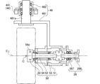
- FIG. 25 is a diagram showing a schematic structure of the spindle section 50 (wheel support section).
- the spindle portion 50 is attached to the lower end portion of the ⁇ rotation frame 461 .
- the spindle unit 50 includes a frame 51 fixed to the ⁇ rotation frame 461, a plurality of (a pair in the illustrated embodiment) bearings 53 attached to the frame 51, and a spindle 52 rotatably supported by the bearings 53. , a 6-component force sensor 54 for detecting the force applied to the test wheel W, and a wheel hub 55 coaxially attached to the tip of the spindle 52 via the 6-component force sensor 54 .
- the 6-component force sensor 54 has a plurality of piezoelectric elements 54e.
- a wheel rim Wr FIG.
- the test wheel W is attached to the wheel hub 55 .
- a torque sensor capable of detecting the torque of the test wheel W may be separately provided in the spindle portion 50 or the like.
- a transmission shaft 266 of the transmission shaft portion 26 is connected to the end of the spindle 52 .
- the transmission shaft 266 is rotatably supported by bearings 267 attached to the frame 51 of the spindle section 50 .
- the alignment unit 40 is arranged so that the position of the test wheel W does not move even if the camber angle ( ⁇ angle) or the slip angle ( ⁇ angle) is changed. It is configured to intersect at one point of the center C of the wheel W.
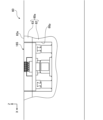
- FIG. 26 is a cross-sectional view of the road surface portion 60.
- the road surface portion 60 includes a frame 61 and a body portion 60 a supported by the frame 61 .
- the body portion 60a includes a base 62 and a paved portion 63 held on the base 62.
- a concave portion 621 is formed on the upper surface of the base 62 so as to extend in the extending direction of the road surface portion 60 (that is, the X-axis direction, which is the running direction of the carriage 20).
- the paved portion 63 is formed, for example, by filling the recesses 621 with a simulated pavement material, which will be described later, and hardening the material.
- a road surface 63 a on which the test wheel W is grounded is formed on the upper surface of the paved portion 63 .
- the main body 60a is composed of a main body unit 600a, which is a road surface unit (exchangeable structure including at least a part of the road surface 63a), and is detachably mounted on the frame 61.
- the road surface unit is not limited to the form in which the main body 60a is unitized (referred to as “main body unit") as in the present embodiment, but the form in which only the paved part 63 is unitized (referred to as "paved part unit"). ) or the entire road surface portion 60 including the frame 61 may be unitized (referred to as a “road surface portion unit”).
- the body portion 60a of the present embodiment is composed of a plurality of body portion units 600a obtained by dividing the body portion 60a in the extending direction of the road surface portion 60, and the body portion units 600a are replaceable.
- the entire body portion 60a may be formed as a single replaceable road surface unit.
- the road surface portion 60 By configuring the road surface portion 60 from road surface units such as the main body unit 600a as in the present embodiment, at least part of the road surface 63a can be easily replaced by replacing the road surface unit.
- replacing only the main body unit 600a in the central portion in the extension direction (X-axis direction) of the road surface portion 60, and changing the type (for example, material, structure, surface shape, etc.) of the paving portion 63 only in the central portion. can be done.
- the type of pavement portion 63 may be changed for each main body unit 600a so that, for example, the coefficient of friction of the road surface 63a changes in the extension direction of the road surface portion 60.
- a concave portion 622 is provided on the lower surface of the base 62 to fit the convex portion 612 provided on the upper surface of the frame 61 .
- the main body unit 600a is mounted on the frame 61 so that the projections 612 and the recesses 622 are fitted, and the two are fixed by fixing means (not shown) such as bolts and cam levers. is detachably mounted on the frame 61 .
- the frame 61 is also formed of a plurality of frame units 610 obtained by dividing the frame 61 in the extending direction of the road surface portion 60, and each frame unit 610 can be replaced.
- the frame unit 610 and the main body unit 600a are formed to have the same length, and the road surface unit 600 with the main body unit 600a attached to the frame unit 610 can be replaced as a unit.
- the paved portion 63 is formed integrally with the base 62, but the paved portion 63 may be detachable from the base 62.
- the pavement portion 63 may be composed of a plurality of pavement portion units 630 obtained by dividing the pavement portion 63 in the extension direction of the road surface portion 60, and the pavement portion 63 may be replaced in units of the pavement portion unit 630.
- the pavement unit 630 and the base unit 620 are formed to have the same length, and the composite unit in which the pavement unit 630 is attached to the base unit 620 (in other words, the main body unit 600a in which the pavement 63 is detachable). may be exchangeable in units of Alternatively, the frame unit 610, the base unit 620, and the pavement unit 630 may be assembled to produce the road surface unit 600, and the road surface unit 600 may be replaceable.
- the road surface portion 60 is formed by connecting a plurality of road surface portion units 600 . With this configuration, it is possible to extend or shorten the road surface portion 60 by adding or removing the road surface portion unit 600 . Further, by making a plurality of road surface units of the same structure, the road surface portion 60 can be manufactured efficiently.
- the track portion 10 is also divided into a plurality of track portion units 100 in the extension direction. It is also possible to extend or shorten the track section 10 by adding or removing the track section unit 100 .
- the track section unit 100 is formed to have the same length as the road surface section unit 600 . Therefore, the lengths of the track portion 10 and the road surface portion 60 can be made uniform.
- the track surface unit 100 and the road surface unit 600 may be integrated as a composite unit unit, and the road surface unit 60 and the track unit 10 may be extended, shortened, or partially replaced.
- a simulated asphalt pavement is formed as the pavement portion 63 (that is, the impact on the tire such as the wear amount of the tire is approximately the same as that of the actual asphalt pavement).
- the simulated pavement is made by pulverizing ceramics with excellent wear resistance such as silicon carbide and alumina (further processed by polishing and etching as necessary), and adding urethane resin, epoxy resin, etc. It is formed by molding and curing a simulated pavement material to which a binder is added. By using such a simulated pavement material, it is possible to obtain a simulated road surface that is excellent in durability and has a stable road surface condition (that is, the amount of wear of the test tire T is stable).
- the wear amount of the tire can be adjusted, for example, by adjusting the particle size of the aggregate, the amount of the binder added, and the like.
- the simulated pavement of this embodiment has a single-layer structure, it is also possible to use a simulated pavement in which a plurality of layers made of different materials are laminated in the thickness direction. Further, for example, by adjusting the type and particle size of aggregate, the type and amount of binder, etc., a simulated pavement simulating paving stone pavement, brick pavement, concrete pavement, or the like may be used.
- the road surface 63a may be formed so that the damage to the tires is greater (or less) than the actual road surface.
- the paved portion 63 may be formed from an actual pavement material (for example, an asphalt mixture used for the surface layer of asphalt pavement). Moreover, the pavement portion 63 may be used that reproduces or imitates actual pavement not only for the outermost layer forming the road surface but also for the lower layer structure.
- an actual pavement material for example, an asphalt mixture used for the surface layer of asphalt pavement.
- the pavement portion 63 may be used that reproduces or imitates actual pavement not only for the outermost layer forming the road surface but also for the lower layer structure.
- the flat type tire testing apparatus 1000 of this embodiment does not move the road surface 63a during the test, so foreign matter (for example, water, snow, muddy water, soil, sand, gravel, fallen leaves, oil, etc.) that affects tire performance can be removed.
- the test can be conducted with a simulated one or a mixture of two or more of these, etc.) sprinkled on the road surface 63a.
- a wet braking test can be conducted by conducting the test with water sprinkled on the road surface 63a.
- FIG. 27 is a cross-sectional view of a road surface portion 60A that is a modified example of the road surface portion 60.
- the road surface portion 60 ⁇ /b>A has a frame portion 67 attached to the base 62 .
- the frame portion 67 is watertightly joined to the base 62 by caulking or the like, and forms a tank 68 together with the base 62 and paved portion 63 .
- the tank 68 is filled with foreign substances (such as water, gravel, soil, fallen leaves, etc.) that affect tire performance so as to cover the road surface 63a. By using the tank 68, it becomes possible to deposit foreign matter thickly on the road surface 63a.
- the frame portion 67 in this modified example is attached to the top surface of the base 62
- the frame portion 67 may be attached to the side surface of the base 62 .
- the frame portion 67 may be attached to the upper surface of the paving portion 63 .
- the road surface portion 60A is provided with temperature adjusting means 64 capable of adjusting the temperature of the road surface 63a.
- the temperature adjusting means 64 of this modified example has a channel 64a embedded in the base 62, a temperature sensor 64b for detecting the temperature of the road surface 63a, and a temperature adjusting device 64c (FIG. 36).
- the temperature sensor 64b is, for example, a contact temperature sensor using a thermocouple or a thermistor, or a non-contact temperature sensor such as an infrared sensor.
- the temperature adjustment device 64c is connected to the control section 1070 and adjusts the temperature of the road surface 63a to the set temperature based on the command from the control section 1070 .
- the temperature adjustment device 64c adjusts the temperature of the heat medium (for example, water containing oil or antifreeze) based on the detection result of the temperature sensor 64b, and sends this heat medium to the flow path 64a.
- the road surface 63a can be adjusted to a predetermined temperature by flowing the heat medium whose temperature is adjusted by the temperature adjustment device 64c through the flow path 64a.
- the surface of the base 62 is covered with a heat insulating material 69 in order to stabilize the temperature of the road surface 63a and improve the heat utilization efficiency.
- the temperature adjustment means 64 can adjust the temperature of the road surface 63a in a wide range from low temperature (eg -40°C) to high temperature (eg 80°C).
- a frozen road surface can be formed by storing water in the tank 68 and setting the set temperature of the road surface 63a below the freezing point. That is, a braking test on ice can be performed by using the road surface portion 60A of this modified example. In addition, a braking test on snow can be performed with the tank 68 filled with snow.
- the flow path 64a is formed so as to meander in the base 62 at regular intervals in parallel with the road surface 63a. Further, the base 62 is divided into a plurality of sections (base units 620) in the extension direction, and each section is provided with an individual flow path 64a. This configuration makes it possible to adjust the temperature of the entire road surface 63a to a more uniform temperature.
- the load detection unit 65 is a component that can detect the load distribution applied to the tire tread.
- 28 and 29 are a plan view and a left side view, respectively, showing the load detecting portion 65 of the road surface portion 60 and its surroundings.
- 30-32 are a front view, a left side view and a plan view of the load detector 65, respectively.
- the upper surface of the body portion 60a of the road surface portion 60 is formed with a recessed portion 60p elongated in the Y-axis direction.
- the load detector 65 is housed in the recess 60p and fixed to the bottom surface of the recess 60p.
- the load detection section 65 includes a fixed frame 658, a movable frame 659, a pair of linear guides 654, a sensor array unit 650, a moving unit 655 and a sensor position detection section 656.
- the movable frame 659 is supported by a pair of linear guides 654 so as to be movable in the Y-axis direction (that is, the width direction of the road surface portion 60).
- the sensor array unit 650 is attached to the top surface of the movable frame 659 . Details of the sensor array unit 650 will be described later.
- FIG. 33 is a plan view showing a state in which the movable portion of the load detection section 65 (that is, the movable frame 659 and the sensor array unit 650) is removed.
- the fixed frame 658 includes a substantially rectangular base plate 658a and a pair of rail support portions 658b fixed to the upper surface of the base plate 658a.
- the pair of rail support portions 658b are arranged with a gap in the X-axis direction with the length direction directed in the Y-axis direction.
- the linear guide 654 includes a rail 654a extending in the Y-axis direction and a plurality (three in this embodiment) of carriages 654b (hereinafter referred to as "runners 654b") capable of running on the rail 654a.
- the rail 654a is attached to the upper surface of the rail support portion 658b.
- Runners 654 b are attached to the lower surface of movable frame 659 .
- the linear guide 654 guides the movement of the movable frame 659 in the Y-axis direction.
- the moving unit 655 is arranged between a pair of rail support portions 658b and linear guides 654.
- the moving unit 655 has a motor 655m and a ball screw 655b.
- the ball screw 655b includes a screw shaft 655ba, a nut 655bb, a bearing portion 655bc and a bearing portion 655bd.
- the motor 655m in this embodiment is a servomotor, another type of motor with a controllable amount of actuation may be used as the motor 655m.
- the screw shaft 655ba is rotatably supported at both ends by a pair of bearings 655bc and 655bd. One end of the screw shaft 655ba is connected to the shaft of the motor 655m. A nut 655bb that meshes with the screw shaft 655ba is attached to the lower surface of the movable frame 659 .
- the screw shaft 655ba is rotated by the motor 655m, the movable frame 659 and the sensor array unit 650 move in the Y-axis direction together with the nut 655bb. That is, the position of the sensor array unit 650 in the Y-axis direction can be changed by rotating the motor 655m.
- the sensor position detection section 656 includes a movable arm 656a, multiple (three in this embodiment) proximity sensors 656c, and a sensor mounting section 656b.
- the movable arm 656a has its distal end fixed to a movable frame 659 and is movable together with the movable frame 659 in the Y-axis direction.
- the sensor attachment portion 656b is attached to a fixed frame 658. As shown in FIG.
- a plurality of proximity sensors 656c are arranged in the Y-axis direction at intervals (for example, at regular intervals) with the detection surface 656cf facing the positive direction of the X-axis, and attached to the sensor attachment portion 656b.
- a proximity part 656ap that is close to the proximity sensor 656c is formed at the tip of the movable arm 656a.
- the proximal portion 656ap is formed by bending the distal end portion of the movable arm 656a into a crank shape.
- the proximity portion 656ap is arranged at the same height as the detection surfaces 656cf of the plurality of proximity sensors 656c. Further, the detection surfaces 656cf of the plurality of proximity sensors 656c are arranged at intervals within the movable range of the proximity portion 656ap in the Y-axis direction.
- FIG. 34 is an enlarged view of area E surrounded by a two-dot chain line in FIG.
- the sensor array unit 650 includes a frame 650a and a plurality (150 in this embodiment) of load detection modules 650m.
- a concave portion 650ap elongated in the Y-axis direction is formed in the central portion of the upper surface of the frame 650a.
- a plurality of load detection modules 650m are housed in the recess 650ap and fixed to the bottom surface of the recess 650ap.
- the plurality of load detection modules 650m are arranged in the form of grid points at equal intervals (for example, substantially without gaps) in two directions, the X-axis direction and the Y-axis direction.
- 150 load detection modules 650m are arranged in 5 rows in the X-axis direction and 30 rows in the Y-axis direction.
- the load detection module 650m includes a 3-component force sensor 651, a paved portion 652, and bolts 653.
- the 3-component force sensor 651 is a columnar piezoelectric element whose center axis is oriented in the Z-axis direction.
- the pavement portion 652 is a rectangular parallelepiped member formed of the same simulated pavement material or pavement material as the pavement portion 63, for example, and having the same length in the X-axis direction and the Y-axis direction. Note that the shapes of the three-component force sensor 651 and the paved portion 652 are not limited to these shapes. For example, the shape of the three-component force sensor 651 may be rectangular parallelepiped, and the shape of the paving portion 652 may be cylindrical.
- a hole 651b penetrating in the Z-axis direction is formed in the center of the cylindrical three-component force sensor 651.
- a bolt hole 652b extending in the Z-axis direction is formed in the center of the paved portion 652 .
- the load detection module 650m is integrated and fixed to the frame 650a by means of bolts 653 passed through the holes 651b of the three-component force sensor 651 and screwed into the bolt holes 652b of the paved portion 652.
- the upper surface of the paved portion 652 is horizontally arranged at the same height to form a road surface 652a.
- the area in the X-axis and Y-axis directions where the load detection modules 650m are arranged serves as the detection area of the sensor array unit 650 .
- the width of the detection area of the sensor array unit 650 (that is, the length in the Y-axis direction) Ly (FIG. 32) is sufficiently wider than the tread width of the test tire T, and the tire tread width of the test tire T is the road surface 652a. can be grounded to
- the 3-component force sensor 651 detects the following three types of forces f R , f T and f L applied to the road surface 652a of each load detection module 650m (that is, applied to the tire tread). a) radial force f R b) tangential force f T c) lateral force f L
- the load detection unit 65 it is possible to detect the distribution of the force applied to the road surface from the tire tread surface of the test tire T (that is, the force applied to the tire tread surface) and its change over time.
- FIG. 35 is a block diagram showing a schematic configuration of the control system 1a of the tire testing system 1.
- the control system 1a includes a central controller 1c for calculating corrected ⁇ -S characteristics, which will be described later, a control system 1000a for controlling the flat tire testing apparatus 1000, and a control system 2000a for controlling the drum type tire testing apparatus 2000.
- the central control unit 1c includes a control unit 70 (computer) having a storage device 72 and an interface unit 90 for input/output with the outside.
- a personal computer, a PCL (Programmable Logic Controller), or a mobile information terminal such as a smart phone is used as the central control device 1c.
- the control system 1a of this embodiment includes three control units 70, 1070, and 2070, but two or more of these may be integrated. In this case, later-described interface units 90, 1090, and 2090 corresponding to the integrated control units 70, 1070, and 2070 are also integrated.
- the interface unit 90 includes, for example, a user interface for performing input/output with a user, a network interface for connecting to various networks such as a LAN (Local Area Network), and a USB (Universal Serial Interface) for connecting to an external device. Bus), GPIB (General Purpose Interface Bus), or one or more of various communication interfaces.
- the user interface includes, for example, various operation switches, displays, various display devices such as LCD (liquid crystal display), various pointing devices such as mice and touch pads, touch screens, video cameras, printers, scanners, buzzers, speakers, etc. , microphone, memory card reader/writer, etc.
- the central control unit 1c is connected to the control systems 1000a and 2000a via a network such as LAN and a bus such as USB. It is possible to control the operations of the flat type tire testing device 1000 and the drum type tire testing device 2000 based on commands from the control section 70 of the central control device 1c. In addition, the test results obtained using the flat type tire testing device 1000 or the drum type tire testing device 2000 are transmitted to the central control device 1c, or stored in a network storage such as the server 92 or NAS (Network Attached Storage). remembered.
- a network storage such as the server 92 or NAS (Network Attached Storage).
- FIG. 36 is a block diagram showing a schematic configuration of a control system 1000a of the flat tire testing device 1000.
- the control system 1000a includes a control section 1070 (computer) that controls the overall operation of the flat tire testing apparatus 1000, a measurement section 1080 that performs various measurements, and an interface section 1090 that performs input/output with the outside.
- the control unit 1070 includes the motor 141 of each driving unit 14, the motor 32 of the torque generating unit 30, the motor 431 of the load adjusting unit 42, the motor 451 of the camber angle adjusting unit 44, the motor 471 of the slip angle adjusting unit 46, and the moving unit.
- a motor 655m of 655 is connected via drivers 141a, 32a, 431a, 451a, 471a and 655a respectively.
- the temperature adjustment device 64c is connected to the control unit 1070 .
- the control unit 1070 and the drivers 141a, 32a, 431a, 451a, and 471a are communicably connected by optical fibers, and high-speed feedback control is possible between the control unit 1070 and the drivers. This enables synchronous control with higher precision (higher resolution and higher accuracy on the time axis).
- the six-component force sensor 54 of the spindle unit 50, the three-component force sensor 651 of the load detection unit 65, and the proximity sensor 656c of the sensor position detection unit 656 are connected to the measurement unit 1080 via amplifiers 54a, 651a, and 656ca, respectively. ing. Signals from the six-component force sensor 54, the three-component force sensor 651, and the proximity sensor 656c are amplified by the amplifiers 54a, 651a, and 656ca, respectively, and then converted into digital signals by the measurement unit 1080, thereby generating measurement data. be. Measurement data is input to the control unit 1070 . Note that FIG. 36 shows only one each of the three-component force sensor 651, the amplifier 651a, the proximity sensor 656c, and the amplifier 656ca.
- phase information detected by the rotary encoder RE built in each motor 141, 32, 431, 451, 471 and 655m is input to the control unit 1070 via each driver 141a, 32a, 451a, 471a and 655a. .
- the control unit 1070 can run the carriage 20 at a predetermined speed by synchronously controlling the driving of the motors 141 of the drive units 14 based on the speed setting data input via the interface unit 76 . .
- all the four drive units 14 are driven in the same phase (more precisely, the left drive units 14LA and 14LB and the right drive units 14RA and 14RB are driven in opposite phase [reverse rotation]). driven).
- control unit 1070 controls the driving of the motor 32 of the torque generation unit 30 based on the setting data of the longitudinal force (braking force or driving force) to be applied to the test tire T acquired through the interface unit 76. , a predetermined longitudinal force can be applied to the test tire T. Further, the control unit 1070 can also apply a predetermined torque to the test wheel W by controlling the torque generation unit 30 based on torque setting data (or acceleration setting data) instead of the longitudinal force setting data. can.
- the control unit 1070 controls the driving unit 14 to run the carriage 20 at a predetermined running speed (at the same time, rotates the test tire T at a peripheral speed substantially equal to the running speed), and applies a longitudinal force (or torque) to the test tire T. can be synchronously performed based on the synchronization signal.
- Waveforms of the torque generated by the torque generator 30 include basic waveforms such as a sine wave, a half sine wave (half sine wave), a sawtooth wave (sawtooth wave), a triangular wave, and a trapezoidal wave, as well as waveforms measured in road tests.
- a longitudinal force (or torque) waveform, a longitudinal force (or torque) waveform obtained by simulation calculations, or any other synthetic waveform can be used.
- the flat type tire testing device 1000 of this embodiment can measure the ⁇ -S characteristics of the test tire T.
- the ⁇ -S characteristic of a tire is the relationship (characteristic ), which is generally represented by a graph with the slip ratio S on the horizontal axis and the friction coefficient ⁇ on the vertical axis.
- the coefficient of friction ⁇ is the ratio of the frictional force acting between the road surface and the contact surface of the tire to the load perpendicular to the road surface and the contact surface of the tire (vertical load) (that is, the friction force divided by the load). value).
- the braking force coefficient ⁇ is a value obtained by dividing the braking force by the load applied to the tire. In tire testing, the braking force coefficient ⁇ is often measured instead of the friction coefficient ⁇ .
- the ⁇ -S characteristic of a tire varies depending on the type of tire, running speed, road surface conditions (dry, wet, etc.) or properties.
- ⁇ -S characteristic measurement method An example of the ⁇ -S characteristic measurement method will be described below.
- measurements are performed a plurality of times while changing the running speed, and ⁇ -S characteristics are obtained for a plurality of different running speeds.
- the control unit 1070 executes a program stored in another storage means that can be accessed by the controller 1070, and measurement results and the like are stored in the storage device 1072 or other storage means.
- the slip ratio S can be calculated by the following formula (1).
- Slip rate S (vehicle speed - wheel peripheral speed)/vehicle speed x 100% (1)
- the vehicle speed is the running speed of the vehicle body (that is, the moving speed of the center of gravity of the vehicle body), and corresponds to the running speed of the carriage 20 in the flat-type tire testing apparatus 1000 of the present embodiment.
- the wheel peripheral speed is the tangential speed of the outer peripheral surface of the wheel (that is, the surface of the tread of the tire), and corresponds to the peripheral speed of the test wheel W in the flat-type tire testing apparatus 1000 of this embodiment.
- the slip ratio is 0%, the vehicle body speed and wheel peripheral speed are equal, the vehicle body is traveling at a speed corresponding to the wheel rotation speed, and there is no slippage or rotation loss.
- the slip ratio is 100%, the wheel peripheral speed is 0. This means that the vehicle body slips (more To be precise, it represents a state in which the tire is slipping on the road surface).
- the measurement can be performed according to the following procedure.
- the flat type tire testing device 1000 is set to the initial state.
- the carriage 20 in the initial state, the carriage 20 is arranged at an initial position (initial travel position) PX0 set near the end of its movable range in the X-axis negative direction.
- the lift frame 421 (FIG. 20) is arranged at an initial position PZ0 set near the upper end of its movable range, for example.
- the test wheel W floats up from the road surface 63a, and attachment/detachment and alignment adjustment of the test wheel W become possible.
- the camber angle and the slip angle are adjusted to the set values by the camber angle adjusting section 44 and the slip angle adjusting section 46, respectively.
- the travel speed for measuring the ⁇ S characteristic for the first time is set. For example, when measuring the ⁇ S characteristic at a speed of 5 km/h, a value of 5 km/h is set in a predetermined memory or the like as the setting value of the running speed.
- test wheel W is lowered by the load adjusting section 42 and touches the road surface 63a, and the set load is applied to the test wheel W.
- the motor 141 of each drive unit 14 is driven, the carriage 20 runs at the set running speed, that is, 5 km/h, and the test wheel W rotates at substantially the same circumferential speed as the carriage 20 running speed.
- the slip rate S since the vehicle body speed ⁇ the wheel peripheral speed, the slip rate S ⁇ 0%.
- the circumferential speed of the test wheel W does not sufficiently match the running speed of the carriage 20, and the difference between the two speeds may generate torque of a magnitude that cannot be ignored. be.
- the slip ratio can be reduced to approximately 0%.
- the motor 32 of the torque generating section 30 is driven to apply the set torque to the test wheel W.
- the three-component force sensor 651 of the load detection unit 65 and the six-component force sensor 54 of the spindle unit 50 detect the , the forces applied to the road surface 652a and the test wheel W are detected, respectively.
- the time interval between detections by the 3-component force sensor 651 and the 6-component force sensor 54 is appropriately set according to the test conditions (for example, the running speed of the carriage 20 and the required test accuracy).
- the torque applied to the test wheel W by the torque generator 30 is controlled so that a predetermined torque is applied while the carriage 20 is running at the set running speed. For example, while running the carriage 20 at a set running speed at a constant speed, the torque ⁇ 0 N ⁇ m, that is, the vehicle body speed ⁇ the wheel peripheral speed, and the slip ratio S ⁇ 0%. The torque is gradually increased, and after the elapse of a predetermined period of time, torque is applied so that the test wheel W is completely locked (that is, the wheel peripheral speed becomes 0 km/h and the slip rate S becomes 100%). controlled as
- the flat tire testing device 1000 of the present embodiment Measurement values are recorded by the various sensors provided.
- the vehicle body speed is calculated from the detection result of the rotary encoder RE of the motor 141 of the drive unit 14, and the wheel peripheral speed is calculated from the detection result of the rotary encoder RE of the torque generation unit 30 and the rotary encoder RE of the motor 32.
- the values of the braking force coefficient ⁇ and the slip ratio S are measured at predetermined time intervals at each measurement timing, and ⁇ -S Properties are measured.
- the required time (test time) for changing the slip ratio S from 0% to 100% can be determined from the balance between the length of the road surface portion 60 and the setting value of the traveling speed of the carriage 20 .
- the length of the road surface portion 60 the length of the road surface necessary for accelerating and decelerating the carriage 20 to a predetermined traveling speed is excluded, and the slippage occurs within the time during which the carriage 20 can travel on the road surface 63a at a predetermined traveling speed. It is possible to control the torque so that the rate S varies from 0% to 100%.
- the predetermined required time for changing the slip ratio S, the set value of the running speed of the carriage 20, or It can be determined according to the required resolution on the time axis.
- the flat-type tire testing apparatus 1000 of the present embodiment is used to measure the ⁇ -S characteristics at the initially set traveling speed of the carriage 20 (eg, 5 km/h).
- the test wheel W is lifted off the road surface 63a, and the carriage 20 is again moved to the end of its movable range in the X-axis negative direction. It is placed at the initial position (initial running position) PX0 set nearby, and prepares for measurement at the next set speed. Then, by changing the set speed and repeating the above measurement, it is possible to sequentially measure the ⁇ S characteristics for a plurality of set speeds.
- a memory area CTM for counting is prepared in the storage device 1072, for example, CTM is counted while incrementing sequentially from 1, and a set speed (for example, CTM ⁇ 5 km/h) is set according to the value of CTM, It is possible to measure the ⁇ S characteristics at that set speed.
- a new test tire T may be replaced each time the value of CTM (that is, the set speed) is changed.
- FIG. 41 is a block diagram showing a schematic configuration of a control system 2000a of the drum-type tire testing device 2000. As shown in FIG.
- the heading direction is defined as the Z2 axis direction.
- the X two- axis direction and the Y two- axis direction are horizontal directions orthogonal to each other, and the Z two- axis direction is the vertical direction.
- the drum-type tire testing apparatus 2000 rotates the rotating drum 2022 and the test tire T for a predetermined time (for example, 24 hours) in a state where the test tire T is grounded on the road surface 2023b provided on the outer periphery of the rotating drum 2022, thereby performing the test. It is an apparatus capable of performing a bench test of a tire in which the tire T is worn under conditions close to the actual running test.
- the drum-type tire testing apparatus 2000 of this embodiment achieves high energy utilization efficiency by adopting an electric motor and a power circulation system in the drive system.
- torque applying section which will be described later, it is possible to independently perform rotation control and torque control by providing dedicated motors for each of the two functions of rotational drive and torque application. It's becoming As a result, torque control with a high degree of freedom and high precision becomes possible, and at the same time, it becomes possible to reduce the capacity of the electric motor, thereby making it possible to reduce the size and power consumption of the test apparatus.
- torque generator 2050 by using an ultra-low inertia servomotor with excellent acceleration performance for the torque generator 2050, it is possible to accurately reproduce torque fluctuations with high frequency components during sudden acceleration and sudden braking. .
- a drum-type tire testing apparatus 2000 includes a tire holding section 2010 that holds a test tire T, a moving road surface section 2020 that has a road surface 2023b on which the test tire T is grounded, a rotation driving section 2030 that rotationally drives a power circulation circuit, and a test tire T.
- a torque generating section 2050 that generates braking force and driving force to be applied to the tire T, and a relay section 2040 that relays power transmission from the rotation driving section 2030 to the torque generating section 2050 are provided.
- the drum-type tire testing apparatus 2000 includes a first connecting means (drive shaft 2062) that connects the rotation driving section 2030 and the relay section 2040, and a second connecting means (drive shaft 2062) that connects the relay section 2040 and the torque generating section 2050.
- V-belt 2066 and third connecting means (constant velocity joint 2064) for connecting torque generating portion 2050 and tire holding portion 2010 (spindle 2152).
- the moving road surface portion 2020, the rotation driving portion 2030, the relay portion 2040, the torque generating portion 2050, and the spindle portion 2015, which will be described later, of the tire holding portion 2010 are annularly connected via the test tire T to form a power circulation circuit.
- the rotating drum 2022 is arranged with its rotation axis directed in the Y2 - axis direction, but for example, the X2 - axis direction, the Z2 - axis direction, or an intermediate direction thereof (for example, the X2 - axis and Z2 -axis direction).
- the rotation axis of the rotating drum 2022 may be oriented in a direction forming an angle of 45° with each of the axes. In that case, the orientation and arrangement of other parts of the drum-type tire testing apparatus 2000 are also changed according to the orientation of the rotating drum 2022 .
- a control system 2000a of the drum-type tire testing apparatus 2000 includes a control unit 2070 (computer) that controls the overall operation of the drum-type tire testing apparatus 2000, and It is provided with a measurement unit 2080 that performs various measurements based on signals from various sensors that have been received, and an interface unit 2090 that performs input/output with the outside.
- a control unit 2070 computer
- a measurement unit 2080 that performs various measurements based on signals from various sensors that have been received
- an interface unit 2090 that performs input/output with the outside.
- the moving road surface portion 2020 includes a rotating drum 2022, a road surface portion 2023 provided on the outer peripheral portion of the rotating drum 2022, and a bearing portion that rotatably supports a shaft 2022a of the rotating drum 2022. 2024.
- the bearing portion 2024 has a rotary encoder 2241 (FIG. 41) that detects the rotation speed of the rotary drum 2022 .
- the road surface portion 2023 of this embodiment is formed by a plurality of road surface units 2231 (FIGS. 42 and 43) that are arranged circumferentially on the outer periphery of the rotary drum 2022 without gaps.
- FIG. 42 is a perspective view of a road surface unit 2231 attached to the outer circumference of the rotating drum 2022.
- FIG. 43 is a cross-sectional view of the road surface unit 2231 cut along the cutting plane HH shown in FIG.
- the road surface unit 2231 is fixed to the frame 2231a by sandwiching the road surface body 2231b between the frame 2231a, the road surface body 2231b (223b1, 2231b2) fitted in the concave portion 2231ad formed on the surface of the frame 2231a, and the frame 2231a.
- a pair of left and right pressing plates 2231c are provided.
- the pressing plate 2231c is detachably fixed to the frame 2231a with a plurality of countersunk screws 2231d.
- a plurality of through holes 2231ah through which bolts for fixing the road surface unit 2231 to the rotary drum 2022 pass are formed at both ends of the frame 2231a in the width direction (horizontal direction in FIG. 43).
- the road surface 2023b is formed by the surfaces of a plurality of road surface bodies 2231b arranged in the circumferential direction.
- the road surface body 2231b of this embodiment is composed of two circumferentially extending portions (left half first portion 2231b1 and right half second portion 2231b2 in FIG. 43) made of different materials.
- the first portion 2231b1 forms a first travel lane 2023b1, which will be described later, and the second portion 2231b2 forms a second travel lane 2023b2.
- the entire road surface body 2231b may be uniformly formed from a single material. Further, the road surface body 2231b of the present embodiment is formed in a cylindrical shape with a smooth surface. Alternatively, unevenness may be provided on the surface in the circumferential direction (or in both the circumferential direction and the width direction) by randomly changing the surface.
- the road surface body 2231b that is formed in advance is attached to the frame 2231a by the pressing plate 2231c.
- 2231b may be directly bolted to frame 2231a.
- the road surface body 2231b may be fixed to the surface of the road surface unit 2231 by filling the concave portion 2231ad with a plastic material such as concrete or a hardening resin and hardening the material.
- the road surface body 2231b contains a curable resin such as urethane resin or epoxy resin in aggregate obtained by pulverizing (further polishing if necessary) ceramics having excellent wear resistance such as silicon carbide or alumina. It is a member that is molded and hardened with a binder added.
- a curable resin such as urethane resin or epoxy resin in aggregate obtained by pulverizing (further polishing if necessary) ceramics having excellent wear resistance such as silicon carbide or alumina. It is a member that is molded and hardened with a binder added.
- the road surface 2023b is divided into two running lanes (a first running lane 2023b1 and a second running lane 2023b2) in the axial direction (width direction) of the rotary drum 2022.
- two driving lanes are formed on the road surface 2023b in this embodiment, a single driving lane or three or more driving lanes may be formed.
- the two running lanes 2023b1 and 2023b2 of the road surface 2023b are formed by changing the particle size and amount of aggregate used.
- the first running lane 2023b1 on the right side in the direction of travel is a simulated road surface that simulates a smooth road surface such as an asphalt paved road surface
- the second running lane 2023b2 on the left side is a simulated road surface that simulates a rough road surface such as stone pavement.
- the rotation drive section 2030 includes a motor 2032 and a power coupling section 2034 that couples the power output from the motor 2032 to the power circulation circuit.
- the motor 2032 is, for example, an inverter motor driven and controlled by an inverter circuit 2032a (Fig. 41).
- Shaft 2032b of motor 2032 is coupled with input shaft 2034a of power coupling portion 2034 .
- One end 2034b1 of the output shaft 2034b of the power coupling portion 2034 is coupled with the shaft 2022a of the rotary drum 2022, and the other end 2034b2 of the output shaft 2034b is coupled with one end of the drive shaft 2062.
- the output shaft 2034b of the power coupling portion 2034 constitutes a part of the power circulation circuit, and the output shaft of the motor 2032 is coupled to the power circulation circuit via the power coupling portion 2034. That is, the motor 2032 rotates the power circulation circuit and controls the rotation speed of the power circulation circuit.
- the relay unit 2040 includes a gear box 2042, a drive pulley 2044, a bearing 10045 that rotatably supports the shaft of the drive pulley 2044, and a tension pulley that applies a predetermined tension to the V-belt 2066 wound around the drive pulley 2044. 2046 and a bearing portion 2047 that rotatably supports the shaft of the tension pulley 2046 .
- the gear box 2042 has a first gear 2042a coupled to the other end of the drive shaft 2062 and a second gear 2042b that meshes with the first gear 2042a.
- the second gear 2042b is coupled with the shaft of the drive pulley 2044.
- the gearbox 2042 converts the rotation input from the drive shaft 2062 into constant-velocity reverse rotation to drive the gear. It is transmitted to pulley 2044 .
- the first gear 2042a and the second gear 2042b can be replaced with gears having a different number of teeth (diameter).
- the number of teeth of the first gear 2042a and the number of teeth of the second gear 2042b may be different so that the gear box 2042 increases or decreases the rotation speed.
- the distance between the rotation axes of the first gear 2042a and the second gear 2042b can be changed.
- the position of the rotation axis of the second gear 2042b is fixed, and the position of the rotation axis of the first gear 2042a is set horizontally (in the direction of distance from the second gear 2042b, that is, in the direction of the X2 axis). It is movable.
- the position of the rotating shaft of the first gear 2042a is laterally moved to adjust the engagement with the second gear 2042b. Equipped with universal joints 2621 at both ends, the rotary drive unit 2030 (specifically, the other end 2034b2 of the output shaft 2034b of the power coupling unit 2034) is driven by a variable length drive shaft 2062 (or a sliding constant velocity joint). and the first gear 2042a are connected. Therefore, even if the first gear 2042a moves laterally, the drive shaft 2062 and the first gear 2042a are not distorted, and the smooth rotation of the power circulation circuit is maintained.
- FIG. 44 is a vertical cross-sectional view of the torque generator 2050 (torque generator).
- the torque generation unit 2050 includes an outer cylinder 2051 (case), a servomotor 2052, a speed reducer 2053 and a shaft 2054 provided in the outer cylinder 2051, and three bearings 2055 and 2055 that rotatably support the outer cylinder 2051. , 2056 , a slip ring portion 2057 (a slip ring 2057 a and a brush 2057 b ), a bearing portion 2058 that rotatably supports the slip ring 2057 a , and a driven pulley 2059 .
- the servomotor 2052 is an ultra-low-inertia high-output AC servomotor with a moment of inertia of the rotating part of 0.01 kg ⁇ m 2 or less and a rated output of 7 kW to 37 kW. As shown in FIG. 41, the servomotor 2052 is connected to the controller 2070 via a servo amplifier 2052a.
- the outer cylinder 2051 has a cylindrical motor housing portion 2512 and a reducer holding portion 2513 with a large diameter, and substantially cylindrical shaft portions 2514 and 2516 with a small diameter.
- a shaft portion 2514 is coaxially coupled to one end (the right end in FIG. 44) of the motor accommodating portion 2512 (that is, so that the axes of rotation coincide with each other).
- a shaft portion 2516 is coaxially coupled to the other end (the left end in FIG. 44) of the motor accommodating portion 2512 via a reducer holding portion 2513 .
- Axial portion 2514 is rotatably supported by bearing portion 2056
- shaft portion 2516 is rotatably supported by a pair of bearing portions 2055 .
- a driven pulley 2059 coupled with the shaft portion 2516 is arranged between the pair of bearing portions 2055 .
- Outer cylinder 2051 is rotationally driven by V-belt 2066 ( FIG. 37 ) wound between driving pulley 2044 of relay portion 2040 and driven pulley 2059 .
- Bearings 2517 are provided at both ends of the inner circumference of the shaft portion 2516 .
- the shaft 2054 is inserted into the hollow portion of the shaft portion 2516 and rotatably supported by the shaft portion 2516 via a pair of bearings 2517 .
- the shaft 2054 passes through the shaft portion 2516 , one end of which protrudes into the reduction gear holding portion 2513 and the other end of which protrudes outside the outer cylinder 2051 .
- a servo motor 2052 is housed in the hollow part of the motor housing part 2512 .
- the servo motor 2052 has its shaft 2521 arranged coaxially with the motor housing portion 2512 , and the motor case is fixed to the motor housing portion 2512 by a plurality of rods 2523 .
- the flange 2522 of the servomotor 2052 is coupled to the gear case 2053a of the speed reducer 2053 via a connecting cylinder 2524 .
- a gear case 2053 a of the speed reducer 2053 is fixed to an inner flange 2513 a of the speed reducer holding portion 2513 .
- the shaft 2521 of the servomotor 2052 is connected to the input shaft 2531 of the reduction gear 2053.
- a shaft 2054 is connected to the output shaft 2532 of the speed reducer 2053 .
- Torque output from servo motor 2052 is amplified by reduction gear 2053 and transmitted to shaft 2054 .
- the rotation of the shaft 2054 is the sum of the rotation of the outer cylinder 2051 driven by the motor 2032 of the rotary drive section 2030 and the rotation driven by the servomotor 2052 .
- a slip ring 2057 a is connected to the shaft portion 2514 of the outer cylinder 2051 .
- a brush 2057b that contacts the slip ring 2057a is supported by a fixed frame 2058a of the bearing portion 2058.
- a cable 2525 of the servo motor 2052 is passed through the hollow portion of the shaft portion 2514 and connected to the slip ring 2057a.
- the brush 2057b is connected to a servo amplifier 2052a (FIG. 41). That is, the servomotor 2052 and the servo amplifier 2052a are connected via the slip ring portion 2057 .
- FIG. 45 is a rear view (partial cross-sectional view) of tire holding portion 2010.
- the tire holding section 2010 is a mechanical section that rotatably holds the test tire T in contact with the road surface 2023b with a predetermined alignment and applying a predetermined load.
- the tire holding section 2010 includes four vertically stacked base plates 2101, 2102, 2103, and 2104, and a spindle section 2015 that holds the test tire T rotatably.
- the tire holding section 2010 includes a traverse mechanism 2011, a camber angle adjusting mechanism 2012, a tire load adjusting mechanism 2013, and a slip angle adjusting mechanism 2014 as alignment mechanisms for the test tire T.
- the alignment mechanism is a mechanism that can adjust the alignment of the test tire T with respect to the road surface 2023b by changing the position or orientation of the spindle portion 2015.
- FIG. 1 is a mechanism that can adjust the alignment of the test tire T with respect to the road surface 2023b by changing the position or orientation of the spindle portion 2015.
- the traverse mechanism 2011 moves the position of the test tire T in the axial direction by moving the base plate 2102 in the YY-axis direction with respect to the base plate 2101, thereby changing the road surface 2023b on which the test tire T is grounded. It is a mechanism for switching between the running lanes 2023b1 and 2023b2.
- the traverse mechanism 2011 includes a plurality of linear guides 2111 that guide the base plate 2102 in the axial direction (YY axis direction) of the rotating drum 2022 with respect to the base plate 2101, a servo motor 2112 that drives the base plate 2102, and rotational motion of the servo motor 2112. is provided with a ball screw 2113 (feed screw mechanism) that converts to linear motion in the YY axis direction.
- the ball screw 2113 has a screw shaft 2113a and a nut 2113b.
- each linear guide 2111 has a rail 2111a and one or more carriages 2111b that can travel on the rail 2111a via rolling elements (not shown).
- a rail 2111 a of the linear guide 2111 is attached to the upper surface of the base plate 2101 and a carriage 2111 b is attached to the lower surface of the base plate 2102 . That is, the base plate 2101 and the base plate 2102 are connected via a plurality of linear guides 2111 so as to be slidable in the YY axis direction.
- a servomotor 2112 is attached to the base plate 2101 with its axis directed in the YY axis direction.
- the shaft of the servomotor 2112 is coupled with the screw shaft 2113a of the ball screw 2113, and the nut 2113b is attached to the lower surface of the base plate 2102.
- the base plate 2102 moves in the YY-axis direction with respect to the base plate 2101 .
- the position of the test tire T relative to the rotating drum 2022 is moved in the YY axis direction, and the running lanes 2023b1 and 2023b2 of the road surface 2023b on which the test tire T is grounded are switched.
- the servo motor 2112 is connected to the controller 2070 via a servo amplifier 2112a.
- a control unit 2070 controls the switching operation of the driving lane by the servo motor 2112 .
- the camber angle adjustment mechanism 2012 is a mechanism that adjusts the camber angle of the test tire T by rotating the base plate 2103 with respect to the base plate 2102 around the Z2 axis.
- the camber angle adjustment mechanism 2012 includes a vertically extending shaft 2121, a bearing 2122 that rotatably supports the shaft 2121, a curved guide 2123 that guides the turning of the base plate 2103 about the shaft 2121, and two axes along the Y2 axis. and a ball screw 2125 (feed screw mechanism) that converts the rotary motion of the servo motor 2124 into linear motion in the Y2 - axis direction.
- the shaft 2121 is attached to the base plate 2103 and the bearing 2122 is attached to the base plate 2102.
- the bearing 2122 is provided with a rotary encoder 2122a (camber angle detection means) shown in FIG. 41 for detecting the angular position (that is, camber angle) of the shaft 2121 .
- the shaft 2121 is arranged directly below the contact surface where the test tire T contacts the rotating drum 2022 .
- the center line (rotational axis) of the shaft 2121 is a straight line passing through the spindle 2152 and the vertical ground plane.
- the curved guide 2123 includes a rail 2123a extending in an arc concentric with the shaft 2121, and a carriage 2123b capable of traveling on the rail 2123a via rolling elements (not shown).
- the rail 2123 a is attached to the upper surface of the base plate 2102 and the carriage 2123 b is attached to the lower surface of the base plate 2103 .
- a screw shaft 2125a of the ball screw 2125 is coupled to the shaft of the servomotor 2124, and a nut 2125b is attached to the base plate 2103 via a hinge 2126 that can swing around the vertical axis.
- the base plate 2103 pivots about the axis 2121 and the camber angle of the test tire T is changed.
- the servomotor 2124 is connected to the controller 2070 via a servo amplifier 2124a.
- the camber angle adjustment operation by the servomotor 2124 is controlled by the controller 2070 .
- the tire load adjustment mechanism 2013 moves the test tire T in the radial direction by moving the base plate 2104 in the X2 - axis direction with respect to the base plate 2103, and adjusts the vertical load (ground pressure) applied to the test tire T. It is a mechanism to The tire load adjustment mechanism 2013 includes a plurality of linear guides 2131 that guide the base plate 2104 with respect to the base plate 2103 in the radial direction (X2 - axis direction) of the rotating drum 2022, a servo motor 2132 that drives the base plate 2104, and a servo motor 2132 that drives the base plate 2104. It has a ball screw 2133 (feed screw mechanism) that converts the rotational motion of the X2 axis into linear motion in the X2 - axis direction.
- the linear guide 2131 includes a rail 2131a extending in the X2 - axis direction and a carriage 2131b capable of traveling on the rail via rolling elements.
- a rail 2131 a of the linear guide 2131 is attached to the upper surface of the base plate 2103 and a carriage 2131 b is attached to the lower surface of the base plate 2104 .
- a servo motor 2132 is attached to the base plate 2103 with its axis directed in the X2 axis direction.
- the shaft of the servomotor 2132 is coupled with the screw shaft 2133a of the ball screw 2133, and the nut 2133b is attached to the base plate 2104.
- the base plate 2104 moves in the X2 - axis direction with respect to the base plate 2103 together with the nut 2133b.
- the center distance between the rotating drum 2022 and the test tire T changes, and the load on the test tire T changes.
- the servomotor 2132 is connected to the controller 2070 via a servo amplifier 2132a.
- the load adjustment operation of the test tire T by the servomotor 2132 is controlled by the controller 2070 .
- the slip angle adjustment mechanism 2014 rotates the spindle part 10015 about the X2 axis with respect to the base plate 2104, thereby tilting the rotation axis of the test tire T about the X2 axis with respect to the rotation axis of the rotary drum 2022. is a mechanism for adjusting the slip angle of the test tire T.
- the slip angle adjusting mechanism 2014 includes a shaft 2141 whose one end is fixed to the spindle case 2154 (bearing portion) of the spindle portion 2015 and extends in the Y2 - axis direction, and the shaft 2141 is rotated around the X2- axis (that is, perpendicular to the ground surface). It is equipped with a bearing 2142 rotatably supported around an axis, a servomotor 2143, and a ball screw 2144 (feed screw mechanism).
- the bearing 2142 has a rotary encoder 2142a (FIG. 41) that detects the angular position of the shaft 2141 (ie, the slip angle of the test tire T).
- a center line (rotational axis) of the shaft 2141 passes through substantially the center of the wheel portion 2156 and is arranged perpendicular to the rotation axis of the wheel portion 2156 .
- the servomotor 2143 is attached to the base plate 2104 via a hinge 2143b that can swing around the Y2 - axis with its axis directed substantially in the Z2 - axis direction.
- the shaft of the servomotor 2143 is coupled with the screw shaft 2144a of the ball screw 2144. As shown in FIG.
- the nut 2144b of the ball screw 2144 is attached to one end of the spindle case 2154 in the X2 - axis direction (separated from the center of the shaft 2141 in the X2- axis direction) via a hinge 2146 that can swing about the Y2- axis. place).
- the servomotor 2143 is connected to the controller 2070 via a servo amplifier 2143a.
- the adjustment operation of the slip angle by the servomotor 2143 is controlled by the controller 2070 .
- the spindle section 2015 includes a spindle 2152 , a spindle case 2154 (bearing section) that rotatably supports the spindle 2152 , and a wheel section 2156 coaxially attached to one end of the spindle 2152 .
- a test tire T is mounted on the wheel portion 2156 .
- the spindle 2152 has a torque sensor 2152a that detects the torque applied to the test tire T, and three component forces applied to the test tire T (i.e., X biaxial force [Radial Force; load], Y biaxial force [Lateral Force]).
- 3-component force sensor 2152b (FIG. 41) for detecting the force in the direction of Z2 axis [Tractive Force].
- the spindle case 2154 also includes a rotary encoder 2154b (Fig. 41) that detects the number of revolutions of the spindle (ie test tire T). Since piezoelectric elements are used for both the torque sensor 2152a and the three-component force sensor 2152b, the spindle 2152 and the spindle case 2154 have high rigidity, which enables highly accurate measurement.
- the wheel portion 2156 also includes an air pressure sensor 2156a (FIG. 41) for detecting the air pressure of the test tire T. As shown in FIG.
- the tire holding section 2010 is equipped with a tire temperature control system 2018 (only the air duct 2182a is shown in FIG. 38) that adjusts the temperature of the test tire T by blowing cold air or hot air onto the test tire T.
- the temperature of the test tire T (in particular, the temperature of the tread surface) during the test (running) affects the test result (amount of wear). Therefore, it is desirable to keep the temperature of the tread surface of the test tire T within a certain temperature range (for example, 35 ⁇ 5° C.) during the test. Also, in the measurement of the wear amount of the test tire T, which will be described later, the temperature of the test tire T affects the measurement results.
- the temperature of the test tire T is adjusted to a set temperature during testing and wear measurement.
- the tire temperature control system 2018 ( FIG. 41 ) comprises a control section 2181 , a spot air conditioner 2182 and a temperature sensor 2183 .
- the temperature sensor 2183 is a non-contact temperature sensor (radiation thermometer) that measures the temperature of the tread surface of the test tire T, and is arranged to face the tread surface. Based on the measurement result of the temperature sensor 2183, the control unit 2181 controls the operation of the spot air conditioner 2182 so as to eliminate the deviation from the set temperature, and blows cool air and warm air onto the tread surface of the test tire T. Or blow room temperature air.
- the preset temperature of the test tire T can be set to different values during testing (during running) and during wear measurement. In addition, different set temperatures can be set according to the type of test tire T.
- the tire temperature control system 2018 may be further provided with a temperature sensor for measuring the room temperature, and based on the room temperature and the temperature of the test tire T, the operation of the spot air conditioner 2182 may be controlled.
- the tire temperature control system 2018 of this embodiment is configured to adjust the temperature of the test tire T by blowing hot air or cold air onto the test tire T using the spot air conditioner 2182.
- the tire temperature control system is not limited to this configuration.
- the temperature of the test tire T may be adjusted by providing a cover (constant room) that surrounds the entire test tire T and adjusting the air temperature inside the cover.
- the set temperature during testing may be set according to the climate of the region where the tire is used. Also, tire wear is accelerated by an increase in temperature. Therefore, an accelerated aging test can also be performed by using the tire temperature control system 2018 to adjust the temperature of the test tire T during testing to be higher than the temperature of the tire during normal driving.
- the tire holding section 2010 also includes a two-dimensional laser displacement sensor 2017 (hereinafter abbreviated as "displacement sensor 2017”) used to measure the wear amount of the tread of the test tire T.
- the displacement sensor 2017 uses a laser light beam (laser light sheet) spread into a strip by a cylindrical lens to obtain a two-dimensional profile of the tread surface of the test tire T (a cross-sectional shape cut by a plane containing the rotation axis of the tire). Non-contact measurement.
- the displacement sensor 2017 is connected to the measuring section 2080 and functions together with the measuring section 2080 as a wear measuring section.
- the measuring section 2080 controls the operation of the displacement sensor 2017 and calculates the wear amount of the test tire T based on the two-dimensional profile acquired by the displacement sensor 2017 .
- the two-dimensional profile measurement by the wear measurement unit is performed before and after the tire test (additionally during the test) while the test tire T is stationary. Based on the two-dimensional profile measured before and after (and during) the test, the wear amount of the test tire T caused by the test is calculated. As described above, the measured value of the tire wear amount is affected by the tire temperature. It is desirable to conduct the test after the tire as a whole has reached a predetermined reference temperature.
- the drum-type tire testing device 2000 of this embodiment described above can also measure the ⁇ -S characteristics of the test tire T in the same manner as the flat-type tire testing device 1000 of this embodiment. Measurement and recording of ⁇ -S characteristics in the drum-type tire testing apparatus 2000 are performed by the controller 2070 shown in FIG. (other storage means accessible by the control unit 2070), and measurement results and the like are stored in the storage device 2072 and other storage means.
- a predetermined initialization process is performed, and the drum-type tire testing device 2000 is set to the initial state.
- the running speed that is, the peripheral speed of the rotating drum 2022
- the running speed for measuring the ⁇ S characteristics for the first time is set. For example, when measuring the ⁇ -S characteristic at a speed of 5 km/h, a value of 5 km/h is set in a predetermined memory or the like.
- the tire load adjustment mechanism 2013 is operated to bring the test tire T into contact with the road surface 2023b provided on the outer circumference of the rotating drum 2022, and the set load is applied to the test wheel W.
- the load applied to each test wheel W is the same, which will be described later.
- the rotating drum 2022 and the test wheel W are rotated by the rotation driving unit 2030, and the rotating drum 2022 rotates at a set circumferential speed (running speed), that is, at an angular speed corresponding to 5 km/h, and the test tire T rotates at substantially the same peripheral speed as the rotating drum 2022 .
- running speed a set circumferential speed
- the peripheral speed of the outer peripheral surface of the rotating drum 2022 is set to It rotates at an angular velocity that corresponds to a set traveling speed (eg, 5 km/h).
- the vehicle body speed ⁇ the wheel peripheral speed, the slip rate S ⁇ 0%, and the peripheral speed of the test wheel W becomes substantially the same as the set running speed (eg, 5 km/h).
- the peripheral speed of the test wheel W does not sufficiently match the peripheral speed of the rotating drum 2022, and the difference in speed between the two produces torque of a magnitude that cannot be ignored.
- the slip ratio can be made approximately 0%. .
- the set torque is applied to the test tire T by the torque generator 2050 .
- the rotating drum 2022 is rotating at a set peripheral speed (running speed), at predetermined time intervals (for example, 5 millisecond intervals), the torque sensor 2152a and the three-component force sensor 2152b apply force to the test tire T.
- the torque and three component forces on the test tire T are detected.
- the time interval between detections by the torque sensor 2152a and the three-component force sensor 2152b is appropriately set according to the test conditions (for example, set value of running speed, required test accuracy, etc.).
- the torque applied to the test tire T by the torque generator 2050 is controlled so that a predetermined torque is applied while the rotating drum 2022 is rotating at the set peripheral speed (running speed). For example, while rotating the rotary drum 2022 at a set peripheral speed (running speed) at a constant speed (constant speed rotation), torque ⁇ 0 N ⁇ m at first, that is, vehicle body speed ⁇ wheel peripheral speed, and slip ratio S ⁇ 0. %, the torque is gradually increased, and after a predetermined time has passed, the test wheel W is completely locked (that is, the wheel peripheral speed becomes 0 km/h and the slip ratio S becomes 100 %) is applied.
- the drum type tire testing device 2000 of the present embodiment Measurement values are recorded by the various sensors provided.
- the traveling speed (peripheral speed of the outer peripheral surface of the rotating drum 2022) is calculated from the detection result of the rotary encoder 2241 and calculated from the detection result of the rotary encoder 2154b.
- the values of the braking force coefficient ⁇ and the slip ratio S are measured at predetermined time intervals at each measurement timing, and the ⁇ -S characteristics at the initially set running speed (eg, 5 km/h) are measured. be done.
- the time required to change the slip ratio S from 0% to 100% is desirably measured under the same conditions as the test time set in the flat-type tire testing apparatus 1000 described above.
- the present invention can be achieved by comparing the respective approximate curves. can be applied as appropriate.
- the ⁇ -S characteristic at the initially set running speed (eg, 5 km/h) is measured using the drum-type tire testing device 2000 of the present embodiment.
- the ⁇ -S characteristic measurement at a certain set speed that is, the set value of the running speed
- the rotation of the rotating drum 2022 and the test tire T is once stopped to prepare for the measurement at the next set speed. Also good.
- a memory area CTM' for counting is prepared, and, for example, CTM' is counted while being incremented sequentially from 1, and a set speed ( For example, it is possible to set CTM′ ⁇ 5 km/h) and measure ⁇ S characteristics at the set speed.
- a set speed For example, it is possible to set CTM′ ⁇ 5 km/h
- the ⁇ -S characteristic (CTM′ 1) at 5 km/h
- the ⁇ -S characteristic (CTM′ 2) at 10 km/h
- drum type tire testing apparatus 2000 having the infinite (endless) road surface 2023b differs from the flat type tire testing apparatus 1000 having the finite length of the road surface 63a. Since it is not subject to , it is possible to test at higher running speeds (in other words, over a wider range of running speeds). It is desirable to perform the drum tire tester 2000 measurements using at least one (and preferably all) of the set speeds used in the flat tire tester 1000 measurements.
- the drum-type tire testing apparatus 2000 is capable of testing at a higher running speed, but since the road surface 2023b has a curvature in the running direction, it accurately reproduces running on a flat actual road surface. I can't.
- the flat type tire testing apparatus 1000 is limited to a relatively low running speed, but since the road surface 63a has no curvature, it is possible to accurately reproduce running on a flat actual road surface.
- the correction of the ⁇ -S characteristic described below is performed using the ⁇ -S characteristic (first ⁇ -S characteristic) measured using the flat tire tester 1000 and the drum-type tire tester 2000.
- FIG. 46 and 47 show the corrected ⁇ from the first ⁇ -S characteristic measured using the flat tire tester 1000 and the second ⁇ -S characteristic measured using the drum-type tire tester 2000.
- 4 is a flow chart illustrating an example of a method for obtaining -S characteristics; The procedures shown in these flowcharts can be executed by the control unit 70 (FIG. 35) reading a predetermined program stored in the storage device 72 and performing processing according to this program. .
- the central controller 1c is configured to sequentially issue measurement commands to the flat tire testing apparatus 1000 and the drum type tire testing apparatus 2000, and obtain corrected ⁇ -S characteristics using the received measurement results.
- the measurement results may be obtained directly from the flat-type tire testing apparatus 1000 or the drum-type tire testing apparatus 2000 via a network such as a LAN or a bus such as a USB, or may be obtained via a network storage such as the server 92 or NAS. You may
- step S1 the control unit 70 sets the counter CTMW to 1.
- the set speed Vw corresponding to the value of the counter CTMW is sequentially set, and the first ⁇ -S characteristic by the flat type tire testing device 1000 and the second ⁇ -S characteristic by the drum type tire testing device 2000 at each set speed Vw. is sequentially compared with the ⁇ -S characteristics of
- the control section 70 acquires and sets the measurement speed Vw corresponding to the counter CTMW (that is, stores it in a predetermined memory such as the storage device 72).
- the measurement speed Vw is obtained, for example, by a predetermined formula such as formula (2).
- Vw 5 x CTMW (km/h) (2)
- the set speed Vw is increased by 5 km/h, and the first and second ⁇ -S characteristics are measured at each set speed Vw to obtain the corrected ⁇ -S characteristics. Become.
- the control unit 70 performs measurement using the flat tire testing device 1000 to acquire the first ⁇ -S characteristic at the measurement speed Vw.
- the control unit 70 when the control unit 70 is connected to the flat tire testing apparatus 1000, commands are sequentially given to the flat tire testing apparatus 1000, and the flat tire testing apparatus 1000 is operated each time. 1 ⁇ -S characteristics may be measured. It is also possible to configure the controller 70 to appropriately read out the first ⁇ -S characteristics that have already been measured by the flat-type tire testing apparatus 1000 and stored in, for example, the server 92 or the like.
- the location where the first ⁇ S characteristic is stored is the internal storage means (eg, storage device 1072) of the flat tire testing apparatus 1000 or the external storage means connected to the flat tire testing apparatus 1000. Alternatively, it may be a separate storage unit that is not connected to the flat type tire testing apparatus 1000 .
- the control unit 70 uses the drum-type tire testing device 2000 of this embodiment to acquire the second ⁇ -S characteristic at the measured speed Vw. Also in this case, similarly to step S3, when the control unit 70 is connected to the drum-type tire testing apparatus 2000, commands are sequentially given to the drum-type tire testing apparatus 2000, and the drum-type tire The test apparatus 2000 may be operated to measure the second ⁇ -S characteristics. It is also possible to configure the controller 70 to appropriately read the second ⁇ -S characteristics that have already been measured by the drum-type tire testing apparatus 2000 and stored in, for example, the server 92 or the like, as necessary.
- the location where the second ⁇ -S characteristic is stored is internal storage means (eg, storage device 2072) of the drum-type tire testing apparatus 2000 or external storage means connected to the drum-type tire testing apparatus 2000.
- a separate storage unit that is not connected to the drum-type tire testing apparatus 2000 may be used.
- control unit 70 controls the measurement result of the first ⁇ -S characteristic at the measurement speed Vw acquired in step S3 and the measurement result of the second ⁇ -S characteristic at the measurement speed Vw acquired in step S4. are compared (step S5).
- the values of the slip ratio S are close (for example, they are substantially the same value)
- the comparison between the first ⁇ -S characteristic and the second ⁇ -S characteristic becomes easy.
- the measured value of the braking force coefficient ⁇ (first braking force coefficient ⁇ 1 ) by the flat tire testing device 1000 and the measurement of the braking force coefficient ⁇ by the drum type tire testing device 2000
- the first braking force coefficient ⁇ 1 and the second braking force A ratio of these is calculated by comparing with the coefficient ⁇ 2 .
- the specific braking force coefficient ⁇ 1 / ⁇ 2 at S 0%, 5%, 10%, 15%, . Then, the values of the specific braking force coefficient ⁇ 1 / ⁇ 2 at each value of the slip ratio S are averaged, and this average value can be used as the conversion coefficient at the measured speed Vw.
- the conversion coefficient means that the second ⁇ -S characteristic measured using the drum-type tire testing apparatus 2000 is converted to the ⁇ -S characteristic corresponding to the first ⁇ -S characteristic obtained by the flat-type tire testing apparatus 1000. This is a parameter for conversion into a characteristic (correction ⁇ S characteristic).
- a general relational expression representing the ⁇ -S characteristic is prepared in advance, and from the first ⁇ -S characteristic measured value by the flat tire testing device 1000, for example, by regression analysis such as the least squares method, A relational expression of the first ⁇ -S characteristics is determined, and on the other hand, from the measured values of the second ⁇ -S characteristics by the drum-type tire tester 2000, the second ⁇ - It is also possible to determine S-characteristic relationships and compare these relationships to determine a conversion factor at the measured velocity Vw.
- the polynomial coefficients (a n(1) , a n ⁇ 1(1) , . . . , a 2 (1) , a 1(1) , a 0(1) ) are determined, while the second ⁇ Determine the coefficients of the polynomials (a n(2) , a n ⁇ 1 (2 ) , . ratio (a n(1) /a n(2) , a n ⁇ 1(1) /a n ⁇ 1(2) , . . . , a 2(1) /a 2(2) , a 1(1) /a 1(2) , a 0(1) /a 0(2) ) can be taken as conversion factors at the measurement speed Vw.
- an estimate of each coefficient of the polynomial representing the first ⁇ -S characteristic is obtained. That is, from the measured value of the second ⁇ -S characteristic at the measurement speed Vw measured using the drum-type tire test device 2000, at the measurement speed Vw obtained when measured using the flat-type tire test device 1000 An estimate of the corrected ⁇ -S characteristic corresponding to the first ⁇ -S characteristic is obtained.
- the control unit 70 determines whether or not comparison of ⁇ -S characteristics has been completed for all measured velocities Vw within the characteristic comparison range (that is, all measured velocities Vw for which ⁇ -S characteristics should be compared).
- the characteristic comparison range refers to the measurement speed Vw at which both the measurement of the first ⁇ -S characteristics by the flat tire testing device 1000 and the measurement of the second ⁇ -S characteristics by the drum-type tire testing device 2000 are performed. is in the range of The characteristic comparison range is, for example, the range of the measurement speed Vw at which the first ⁇ -S characteristic is measured by the flat tire testing apparatus 1000 (that is, the minimum speed of the measurement speed Vw at which the first ⁇ -S characteristic is measured (eg 5 km/h) to a maximum speed (eg 60 km/h)).
- both the flat tire testing device 1000 and the drum type tire testing device 2000 have ⁇ - The S characteristics are measured and the measurement results are compared, and for the higher speed range (outside the characteristic comparison range), the measurement results of the second ⁇ -S characteristics measured by the drum type tire tester 2000 are compared with the flat type. It is possible to convert to a ⁇ -S characteristic (ie, a corrected ⁇ -S characteristic) corresponding to the first ⁇ -S characteristic by the tire testing apparatus 1000 .
- the flat type tire testing apparatus 1000 Since the flat type tire testing apparatus 1000 is capable of measuring in a state closer to the running condition on the actual road surface, the flat type tire testing apparatus 1000 is used to measure the first ⁇ -S characteristics.
- the predetermined speed range characteristic comparison range
- the first ⁇ -S characteristic measured by the flat tire tester 1000 is adopted as the measurement result of the ⁇ -S characteristic of the test tire T, and the speed is higher than that.
- the corrected ⁇ -S characteristic converted from the second ⁇ -S characteristic measured by the drum type tire testing device 2000 is used as the measurement result of the ⁇ -S characteristic of the test tire T. It is possible to adopt.
- step S6 If it is determined in step S6 that the comparison of ⁇ S characteristics (characteristic comparison processing) in the characteristic comparison range has not been completed (step S6: NO), the control unit 70 adds 1 to the counter CTMW (step S7 ), the process returns to step S2 to perform characteristic comparison processing (S2-S5) at the measurement speed Vw corresponding to the next CTMW value.
- step S6 determines whether the comparison of the ⁇ -S characteristics in the characteristic comparison range has ended (step S6: YES).
- the control unit 70 advances the process to step S8, and performs each measurement within the characteristic comparison range. From the relationship between the first ⁇ -S characteristic and the second ⁇ -S characteristic measured for the speed Vw, the ⁇ -S characteristic by the flat type tire testing device 1000 and the drum type tire testing device at speeds outside the characteristic comparison range. 2000 to estimate the relationship with ⁇ -S characteristics.
- the average value of the ratio (specific braking force coefficient ⁇ 1 / ⁇ 2 ) to the second braking force coefficient ⁇ 2 measured by the test device 2000 at each slip ratio can be used as a conversion coefficient.
- a method of using it as a conversion factor (ratio factor) between the -S characteristic and the second ⁇ S characteristic is possible.
- the conversion coefficient is regarded as a linear function of the measurement speed Vw, and a relational expression between the measurement speed Vw and the conversion coefficient is determined by linear regression analysis (for example, linear approximation by the least squares method), and an arbitrary measurement speed Vw You may enable it to calculate a conversion coefficient about.
- Conversion factor CF(V) proportionality constant c1 ⁇ measuring speed V+constant c2 (3)
- the relationship between the conversion coefficient and the measurement speed V (Vw or Vs described later) can be approximated by a relational expression such as Equation (3). can decide.
- the first ⁇ -S characteristic by the flat type tire testing device 1000 and the second ⁇ -S characteristic by the drum type tire testing device 2000 are the conversion coefficient CF (V). Therefore, in this case, in the characteristic estimation process S12, which will be described later, a conversion coefficient corresponding to the measured speed Ws is obtained from this relational expression for each measured speed Ws, and used for calculation of the corrected ⁇ -S characteristic. .
- step S5 the first braking force coefficient ⁇ 1 and the second braking force coefficient ⁇ 2 measured by the drum-type tire tester 2000 (specific braking force coefficient ⁇ 1 / ⁇ 2 ) was averaged, and this average value was used as the conversion coefficient at the measured speed Vw.
- the invention is not limited to this configuration.
- the relationship that is, the conversion coefficient
- the slip rate S 10%
- step S9 the control unit 70 sets the counter CTMS to 1.
- set speeds Vs within the characteristic estimation range according to the value of the counter CTMS are sequentially set, and from the measurement results of the second ⁇ -S characteristic by the drum-type tire testing device 2000 at each set speed Vs, Estimation of the first .mu.-S characteristic (in other words, calculation of the corrected .mu.-S characteristic corresponding to the first .mu.-S characteristic) by the flat type tire testing apparatus 1000 is sequentially performed.
- the control unit 70 sets the measurement speed Vs according to the counter CTMS as the measurement speed Vs.
- the measurement speed Vs is obtained, for example, by a predetermined formula such as formula (4).
- Vs 5 x CTMS + Vss (km/h) (4)
- the constant Vss for example, the maximum speed among the measured speeds Vw within the characteristic comparison range set in step S2 can be used. That is, by setting the constant Vss to the upper limit of the characteristic comparison range, it is possible to start estimating the characteristic from a speed exceeding the characteristic comparison range.
- the characteristic estimation can be started from the maximum speed of the measured speed Vw set in step S2+5 km/h as the characteristic comparison range.
- the corrected ⁇ -S characteristic at each set speed Vs is acquired sequentially while increasing the measured speed Vs by 5 km/h.
- step S2 a table in which the values of the counter CTMS and the values of the measurement speed Vs are associated with each other is prepared in advance in a memory or the like, and the value of the measurement speed Vs corresponding to the value of the counter CTMS is stored. It is also possible to obtain and set the measurement speed Vw by reading from the table.
- the control unit 70 performs measurement using the drum-type tire testing device 2000 and obtains the second ⁇ -S characteristic at the measurement speed Vs. Also in this case, similarly to steps S3 and S4, when the control unit 70 is connected to the drum-type tire testing apparatus 2000, commands are sequentially given to the drum-type tire testing apparatus 2000, and the drum is controlled each time. A second ⁇ -S characteristic may be measured by operating the model tire testing apparatus 2000 . It is also possible to configure the controller 70 to appropriately read the second ⁇ -S characteristics that have already been measured by the drum-type tire testing apparatus 2000 and stored in, for example, the server 92 or the like, as necessary.
- the location where the second ⁇ -S characteristic is stored is internal storage means (eg, storage device 2072) of the drum-type tire testing apparatus 2000 or external storage means connected to the drum-type tire testing apparatus 2000.
- a separate storage unit that is not connected to the drum-type tire testing apparatus 2000 may be used.
- the control unit 70 uses the relationship between the first ⁇ -S characteristic and the second ⁇ -S characteristic estimated in step S8 (that is, the conversion coefficient) to determine the speed at the measurement speed Vs measured in step S11.
- a corrected ⁇ -S characteristic corresponding to the first ⁇ -S characteristic at the measurement speed Vs is estimated by converting the second ⁇ -S characteristic (step S12).
- the conversion is performed using the slip ratio S and the measured speed Vs measured in step S11 as appropriate. conduct.
- the conversion factor CF(Vs) at the measurement speed Vs is obtained by the following equation (5).
- Conversion factor CF (Vs) proportional constant c1 ⁇ measuring speed Vs+constant c2 (5)
- the second ⁇ -S characteristic obtained by the drum-type tire testing device 2000 can be converted into a corrected ⁇ -S characteristic corresponding to the first ⁇ -S characteristic obtained by the flat-type tire testing device 1000. can.
- the control unit 70 acquires all the measurement speeds Vs within the characteristic estimation range (that is, the corrected ⁇ -S characteristics are acquired in step S13). It is determined whether or not acquisition of corrected ⁇ -S characteristics has been completed for all measurement velocities (Vs) to be measured.
- the characteristic estimation range is the range of the measurement speed Vs for acquiring the corrected ⁇ S characteristic (S10-S12).
- the characteristic estimation range is, for example, a range of speeds higher than the characteristic comparison range, and the upper limit is, for example, the maximum speed measurable by the drum-type tire testing device 2000. It is possible to set the characteristic estimation range. . Alternatively, it is also possible to set the speed range in which it is necessary to acquire the corrected ⁇ S characteristic as the characteristic estimation range. Furthermore, it is also possible to set a speed range in which a predetermined accuracy is guaranteed as a characteristic estimation range for the ⁇ -S characteristic conversion method (estimation method) acquired in step S8 and used in step S12. .
- step S13 If it is determined in step S13 that the characteristic estimation range has not ended (step S13: NO), the control unit 70 adds 1 to the counter CTMS (step S14), returns to step S10, and returns to the next counter CTMS. Characteristic estimation processing S12 is performed at the measurement speed Vs corresponding to the value of .
- step S13 determines the number measured by the flat tire testing apparatus 1000 at each measurement speed Vw within the characteristic comparison range
- the ⁇ -S characteristics of 1 and the corrected ⁇ -S characteristics calculated from the second ⁇ -S characteristics measured by the drum-type tire testing device 2000 at each measurement speed Vw within the characteristic estimation range are connected ( That is, by synthesizing), a synthesized ⁇ S characteristic over the entire range is generated (step S15).
- the flat type tire testing apparatus 1000 with a flat road surface is capable of measuring in a state closer to the running condition on the actual road surface. Therefore, at each measurement speed Vw within the characteristic comparison range, The first ⁇ -S characteristic measured using the flat tire testing device 1000 is used as it is, and at each measurement speed Vs within the characteristic estimation range, the second measured using the drum type tire testing device 2000 to obtain a corrected ⁇ -S characteristic corresponding to the first ⁇ -S characteristic by the flat tire testing device 1000, and these ⁇ -S characteristics (that is, within the characteristic comparison range By connecting the first ⁇ -S characteristic and the corrected ⁇ -S characteristic within the characteristic estimation range), a synthesized ⁇ -S characteristic ("extended ⁇ -S characteristic”).
- the conversion relationship (that is, the conversion coefficient) between the second ⁇ -S characteristic by the drum type tire testing device 2000 and the first ⁇ -S characteristic by the flat type tire testing device 1000 is expressed as the actual measured value.
- the method of acquiring by comparing is described, it is not limited to this, and for example, it is also possible to set the conversion method in advance.
- the first ⁇ -S characteristic measured by the flat tire tester 1000 is used, and in the relatively high speed range (high speed range), the drum type tire
- the second ⁇ -S characteristic measured by the test apparatus 2000 is converted by a preset conversion method to obtain the corrected ⁇ -S characteristic, and the first ⁇ -S characteristic in the low speed range and the corrected ⁇ in the high speed range are obtained. It is possible to stitch together -S characteristics.
- a conversion method based on road surface curvature correction may be adopted based on the structural difference between the flat type tire testing device 1000 and the drum type tire testing device 2000 (specifically, the presence or absence of road surface curvature). is possible.
- braking force is applied to the test tire T by the torque generating section 30 (flat type tire testing device 1000) or the torque generating section 2050 (drum type tire testing device 2000),
- ⁇ -S characteristics when braking is mainly explained, but it is not limited to this, it is also possible to measure ⁇ -S characteristics during acceleration (traction side).
- the above-mentioned torque generation section 30 /torque generation section 2050 can be implemented by generating torque in the same direction as the rotation of the test tire in the direction of further increasing the speed, and these torque generation
- the section 30/torque generating section 2050 operates as a slip ratio control device capable of controlling the slip ratio. That is, it can be realized by incorporating a slip ratio control device into the power circulation circuit.
- the measurement of the ⁇ -S characteristic of the test tire T and the wear test of the test tire described above can be carried out in common by one device.
- the appropriate gear ratio may differ between the measurement of the ⁇ -S characteristic of the tire and the wear test of the tire due to the difference in test speed.
- a gear for high-speed driving suitable for S characteristic measurement, etc., and a gear for low-speed driving suitable for tire wear testing, etc. are configured to be switchable (for example, the gear box 2042 and the reduction gear 2053 are used as a transmission device). ), and by switching the gear according to the application, it is possible to share the measurement of the ⁇ -S characteristics of the test tire T and the wear test of the same test tire T with one device.
- the gear is changed as it is, and the wear test is performed, and the test tire T that has been worn after running for a predetermined time is measured. Furthermore, it is possible to switch the gear as it is and measure the ⁇ -S characteristic after use. Abrasion test and ⁇ -S characteristic measurement can be performed in a series of steps without replacing the tire, etc., and the ⁇ -S characteristic of the tire that has been worn for a predetermined time is measured, and furthermore, it is worn for a predetermined time. It is possible to perform flexible tests such as measuring ⁇ -S characteristics from the
- a power circulation system using a servomotor is adopted in the drive system, a slip ratio control device is incorporated in this power circulation circuit, and By using a gear with a suitable gear ratio, it is possible to finely control the torque (braking force/acceleration force) given by the torque generating section 30/torque generating section 2050, and the slip ratio can be controlled with high precision. Various tire tests can be performed.
- gear reduction ratios for example, gear reduction ratios (gear ratios) of 100, 50, 15, 10, 7.5, 5, 3, 2, 1, fractions, 1/10, 1/20, 1/30 , 1/40th, 1/50th, 1/60th, 1/70th, 1/80th, 1/90th, 1/100th, etc. It can be used as appropriate according to the type of tire to be tested, the contents of the test, the configuration of the device, etc. Using a gear with such a reduction ratio can improve the measurement accuracy. In particular, when measuring the slip ratio S with high accuracy, it is desirable to set a high speed reduction ratio.
- the drum-type tire testing apparatus 2000 (flat-type tire testing apparatus 1000) of the present embodiment uses a power circulation system to rotate the rotating drum 2022 (carriage 20) and the test wheel W by a common motor 141 (motor 2032). Since the rotation speed of the rotating drum 2022 (running speed of the carriage 20) and the rotation speed of the test wheel W are automatically driven at approximately the same speed, the rotation speed (running speed) must be controlled with high accuracy. is possible. In particular, fluctuations in speed on the time axis can be kept low.
- the slip ratio S can be measured with high accuracy with an error of 0.01% or less.
- the ⁇ -S characteristic measured on the actual road surface and the ⁇ -S characteristic measured by the drum type tire testing device 2000 are used. It is also possible to make comparisons, determine conversion relationships, and estimate ⁇ -S characteristics in speed ranges that are difficult to measure on actual road surfaces, using the method of this embodiment.
- a tire road test device traction bus
- the operations of the flat type tire testing apparatus 1000 and the drum type tire testing apparatus 2000 are integrated under the control unit 70.
- the tire testing device 1000 and the drum-type tire testing device 2000 can be used individually as independent testing devices for testing.
- toothed belts and toothed pulleys are used for each of the belt mechanisms 15, 24, 25, 142, but flat belts or V-belts are used in place of toothed belts for one or more of the belt mechanisms.
- flat belts or V-belts are used in place of toothed belts for one or more of the belt mechanisms.
- another type of winding transmission mechanism such as a chain transmission mechanism or a wire transmission mechanism may be used.
- other types of power transmission mechanisms such as a ball screw mechanism, a gear transmission mechanism, or a hydraulic mechanism may be used.
- the location where the driven pulley 242 (FIG. 19) is attached to the rotating frame 31 is not limited to the shaft portion 314, and may be other locations such as the first tubular portion 311, the second tubular portion 312, and the third tubular portion 313.
- the tip portion of the shaft portion 314 does not need to protrude from the bearing portion 351 .
- the bearing portion 353 that supports the tip portion of the shaft portion 314 becomes unnecessary.
- the shaft 34 may be directly supported by the bearing portion 353 .
- the drive pulley 251 may be arranged between the bearing portion 351 and the bearing portion 353 .
- the torque generators 30, 2050 are provided with the reducers 33, 2053, but the torque generators 30, 2050 may not be provided with the reducers.
- the drum-type tire testing device 2000 includes the gearbox 2042, but the drum-type tire testing device may not include the gearbox.
Landscapes
- Physics & Mathematics (AREA)
- General Physics & Mathematics (AREA)
- Engineering & Computer Science (AREA)
- Mechanical Engineering (AREA)
- Tires In General (AREA)
Priority Applications (5)
| Application Number | Priority Date | Filing Date | Title |
|---|---|---|---|
| CN202280068062.9A CN118076871A (zh) | 2021-10-08 | 2022-10-07 | 轮胎测试方法、轮胎测试系统和程序 |
| JP2023552984A JPWO2023058777A1 (https=) | 2021-10-08 | 2022-10-07 | |
| EP22878644.8A EP4414681A4 (en) | 2021-10-08 | 2022-10-07 | TIRE TESTING METHOD, TIRE TESTING SYSTEM AND PROGRAM |
| KR1020247012028A KR20240088827A (ko) | 2021-10-08 | 2022-10-07 | 타이어 시험 방법, 타이어 시험 시스템 및 프로그램 |
| US18/623,382 US20240264044A1 (en) | 2021-10-08 | 2024-04-01 | Tire testing method, tire testing device, and computer-readable medium |
Applications Claiming Priority (2)
| Application Number | Priority Date | Filing Date | Title |
|---|---|---|---|
| JP2021166397 | 2021-10-08 | ||
| JP2021-166397 | 2021-10-08 |
Related Child Applications (1)
| Application Number | Title | Priority Date | Filing Date |
|---|---|---|---|
| US18/623,382 Continuation-In-Part US20240264044A1 (en) | 2021-10-08 | 2024-04-01 | Tire testing method, tire testing device, and computer-readable medium |
Publications (1)
| Publication Number | Publication Date |
|---|---|
| WO2023058777A1 true WO2023058777A1 (ja) | 2023-04-13 |
Family
ID=85804406
Family Applications (1)
| Application Number | Title | Priority Date | Filing Date |
|---|---|---|---|
| PCT/JP2022/037743 Ceased WO2023058777A1 (ja) | 2021-10-08 | 2022-10-07 | タイヤ試験方法、タイヤ試験システムおよびプログラム |
Country Status (7)
| Country | Link |
|---|---|
| US (1) | US20240264044A1 (https=) |
| EP (1) | EP4414681A4 (https=) |
| JP (1) | JPWO2023058777A1 (https=) |
| KR (1) | KR20240088827A (https=) |
| CN (1) | CN118076871A (https=) |
| TW (1) | TW202316090A (https=) |
| WO (1) | WO2023058777A1 (https=) |
Cited By (1)
| Publication number | Priority date | Publication date | Assignee | Title |
|---|---|---|---|---|
| EP4455631A1 (en) * | 2023-04-27 | 2024-10-30 | Sumitomo Rubber Industries, Ltd. | Method for forming snow surface for tire evaluation |
Families Citing this family (1)
| Publication number | Priority date | Publication date | Assignee | Title |
|---|---|---|---|---|
| TWI885569B (zh) * | 2023-11-08 | 2025-06-01 | 系統電子工業股份有限公司 | 胎壓偵測器喚醒裝置 |
Citations (7)
| Publication number | Priority date | Publication date | Assignee | Title |
|---|---|---|---|---|
| JP2007132885A (ja) * | 2005-11-14 | 2007-05-31 | Railway Technical Res Inst | 車両試験装置 |
| JP2012002755A (ja) * | 2010-06-18 | 2012-01-05 | Sumitomo Rubber Ind Ltd | タイヤの氷上制動性能の評価方法 |
| JP2014181958A (ja) * | 2013-03-18 | 2014-09-29 | Toyo Tire & Rubber Co Ltd | 湿潤路面測定装置、測定方法及び試験路面 |
| JP2018119814A (ja) * | 2017-01-23 | 2018-08-02 | 住友ゴム工業株式会社 | タイヤの制動性能評価方法 |
| WO2019026733A1 (ja) | 2017-08-03 | 2019-02-07 | 国際計測器株式会社 | タイヤ試験方法、タイヤ試験装置及び散布装置 |
| WO2019203359A1 (ja) | 2018-04-20 | 2019-10-24 | 国際計測器株式会社 | タイヤ試験装置 |
| WO2020241323A1 (ja) | 2019-05-24 | 2020-12-03 | 国際計測器株式会社 | タイヤ試験装置 |
Family Cites Families (1)
| Publication number | Priority date | Publication date | Assignee | Title |
|---|---|---|---|---|
| US9038449B2 (en) * | 2010-04-16 | 2015-05-26 | Camber Ridge, Llc | Tire testing systems and methods |
-
2022
- 2022-10-07 JP JP2023552984A patent/JPWO2023058777A1/ja active Pending
- 2022-10-07 KR KR1020247012028A patent/KR20240088827A/ko active Pending
- 2022-10-07 EP EP22878644.8A patent/EP4414681A4/en active Pending
- 2022-10-07 CN CN202280068062.9A patent/CN118076871A/zh active Pending
- 2022-10-07 TW TW111137954A patent/TW202316090A/zh unknown
- 2022-10-07 WO PCT/JP2022/037743 patent/WO2023058777A1/ja not_active Ceased
-
2024
- 2024-04-01 US US18/623,382 patent/US20240264044A1/en active Pending
Patent Citations (7)
| Publication number | Priority date | Publication date | Assignee | Title |
|---|---|---|---|---|
| JP2007132885A (ja) * | 2005-11-14 | 2007-05-31 | Railway Technical Res Inst | 車両試験装置 |
| JP2012002755A (ja) * | 2010-06-18 | 2012-01-05 | Sumitomo Rubber Ind Ltd | タイヤの氷上制動性能の評価方法 |
| JP2014181958A (ja) * | 2013-03-18 | 2014-09-29 | Toyo Tire & Rubber Co Ltd | 湿潤路面測定装置、測定方法及び試験路面 |
| JP2018119814A (ja) * | 2017-01-23 | 2018-08-02 | 住友ゴム工業株式会社 | タイヤの制動性能評価方法 |
| WO2019026733A1 (ja) | 2017-08-03 | 2019-02-07 | 国際計測器株式会社 | タイヤ試験方法、タイヤ試験装置及び散布装置 |
| WO2019203359A1 (ja) | 2018-04-20 | 2019-10-24 | 国際計測器株式会社 | タイヤ試験装置 |
| WO2020241323A1 (ja) | 2019-05-24 | 2020-12-03 | 国際計測器株式会社 | タイヤ試験装置 |
Non-Patent Citations (1)
| Title |
|---|
| See also references of EP4414681A4 |
Cited By (1)
| Publication number | Priority date | Publication date | Assignee | Title |
|---|---|---|---|---|
| EP4455631A1 (en) * | 2023-04-27 | 2024-10-30 | Sumitomo Rubber Industries, Ltd. | Method for forming snow surface for tire evaluation |
Also Published As
| Publication number | Publication date |
|---|---|
| EP4414681A4 (en) | 2025-10-08 |
| KR20240088827A (ko) | 2024-06-20 |
| CN118076871A (zh) | 2024-05-24 |
| TW202316090A (zh) | 2023-04-16 |
| EP4414681A1 (en) | 2024-08-14 |
| US20240264044A1 (en) | 2024-08-08 |
| JPWO2023058777A1 (https=) | 2023-04-13 |
Similar Documents
| Publication | Publication Date | Title |
|---|---|---|
| JP7618280B2 (ja) | タイヤ試験装置 | |
| JP7730198B2 (ja) | タイヤ試験装置 | |
| JP7644950B2 (ja) | タイヤ試験装置 | |
| US20240264044A1 (en) | Tire testing method, tire testing device, and computer-readable medium | |
| KR20240087765A (ko) | 차륜 시험 시스템 | |
| RU2836068C1 (ru) | Устройство для испытаний шин | |
| RU2819633C1 (ru) | Устройство для испытаний шин |
Legal Events
| Date | Code | Title | Description |
|---|---|---|---|
| 121 | Ep: the epo has been informed by wipo that ep was designated in this application |
Ref document number: 22878644 Country of ref document: EP Kind code of ref document: A1 |
|
| WWE | Wipo information: entry into national phase |
Ref document number: 2401001823 Country of ref document: TH |
|
| WWE | Wipo information: entry into national phase |
Ref document number: 2023552984 Country of ref document: JP |
|
| WWE | Wipo information: entry into national phase |
Ref document number: 202280068062.9 Country of ref document: CN |
|
| WWE | Wipo information: entry into national phase |
Ref document number: 202417030198 Country of ref document: IN |
|
| WWE | Wipo information: entry into national phase |
Ref document number: 2022878644 Country of ref document: EP |
|
| NENP | Non-entry into the national phase |
Ref country code: DE |
|
| ENP | Entry into the national phase |
Ref document number: 2022878644 Country of ref document: EP Effective date: 20240508 |
|
| WWE | Wipo information: entry into national phase |
Ref document number: 11202402073X Country of ref document: SG |