WO2023058384A1 - 制御装置および方法 - Google Patents
制御装置および方法 Download PDFInfo
- Publication number
- WO2023058384A1 WO2023058384A1 PCT/JP2022/033379 JP2022033379W WO2023058384A1 WO 2023058384 A1 WO2023058384 A1 WO 2023058384A1 JP 2022033379 W JP2022033379 W JP 2022033379W WO 2023058384 A1 WO2023058384 A1 WO 2023058384A1
- Authority
- WO
- WIPO (PCT)
- Prior art keywords
- node
- processing
- information
- nodes
- control device
- Prior art date
- Legal status (The legal status is an assumption and is not a legal conclusion. Google has not performed a legal analysis and makes no representation as to the accuracy of the status listed.)
- Ceased
Links
Images


Classifications
-
- G—PHYSICS
- G05—CONTROLLING; REGULATING
- G05B—CONTROL OR REGULATING SYSTEMS IN GENERAL; FUNCTIONAL ELEMENTS OF SUCH SYSTEMS; MONITORING OR TESTING ARRANGEMENTS FOR SUCH SYSTEMS OR ELEMENTS
- G05B15/00—Systems controlled by a computer
- G05B15/02—Systems controlled by a computer electric
-
- G—PHYSICS
- G01—MEASURING; TESTING
- G01N—INVESTIGATING OR ANALYSING MATERIALS BY DETERMINING THEIR CHEMICAL OR PHYSICAL PROPERTIES
- G01N35/00—Automatic analysis not limited to methods or materials provided for in any single one of groups G01N1/00 - G01N33/00; Handling materials therefor
Definitions
- the present invention relates to a control device and method, and more particularly to a control device for controlling an experimental device based on an experimental protocol and a method for controlling an experimental device based on the experimental protocol.
- Patent Document 1 acquires and displays a graph in which a chain of experiments is formed in a mesh pattern from a database containing information about experimental protocols.
- control device sequentially executes each processing based on the experimental protocol.
- the control of the control device can be simplified because the process proceeds to the next process after waiting for the completion of one process.
- the control device only needs to sequentially execute a plurality of processes included in the experimental protocol as a set of instructions having a one-dimensional array structure.
- An experimental protocol that includes such parallel processing can be created relatively easily by using a directed graph.
- the processing of the experimental equipment is represented by nodes, and the anteroposterior relationship of multiple processes is represented by edges. Edges go from earlier processing nodes to later processing nodes.
- a certain node and a plurality of nodes should be connected by edges.
- control device executes an experimental protocol that includes parallel processing.
- a control device that waits for the completion of one process and repeats control to proceed to the next process cannot manage the order of a plurality of processes branching from one process and proceeding in parallel.
- the present invention was made to solve such problems, and its purpose is to increase the efficiency of experiments based on experimental protocols created with directed graphs.
- a control device is a control device that controls an experimental device based on an experimental protocol.
- the control device includes an input unit that receives input of an experiment protocol designed as a directed graph including a plurality of nodes corresponding to the processing of the experiment, and a first node and a second node that becomes executable upon completion of the processing of the first node.
- a generator for generating a dependency list including first dependency information indicating that the start of the process of the second node depends on the completion of the process of the first node when included in the plurality of nodes; a selection unit that selects a node to start processing from based on the dependency list, a command unit that commands the experimental device to process the node selected by the selection unit, and one of the processing of a plurality of nodes is completed an updating unit for updating the dependency list or the states of the plurality of nodes when the processing is completed, and the selecting unit selects the second node when the processing of the first node is completed.
- a method is a method of controlling an experimental device based on an experimental protocol.
- the method comprises the steps of accepting input of an experiment protocol designed as a directed graph including a plurality of nodes corresponding to operations of the experiment; generating a dependency list including first dependency information indicating that, if included in the node, the start of processing of the second node depends on the completion of processing of the first node; selecting a node to be started based on the dependency list; instructing the experimental device to process the node selected by the selector; Updating the relationship list or states of the plurality of nodes, and selecting a node to start processing selects a second node when processing of the first node is complete.
- FIG. 1 is a block diagram showing the configuration of an automatic experiment management system 1000;
- FIG. 3 is a block diagram showing the hardware configuration of terminal device 400.
- FIG. FIG. 5 is a diagram showing the GUI configuration of an experiment protocol design application 500;
- FIG. 10 is a diagram showing how a certain process is selected in the automatic experiment system window;
- FIG. 10 is a diagram showing how a processing node corresponding to the selected process has been added to the protocol design window;
- FIG. 10 is a diagram showing a directed graph DG1 as a design example of an experimental protocol;
- 3 is a diagram showing a directed graph DG2 including action nodes of the robot arm 121;
- FIG. 13 is a diagram showing a directed graph DG3;
- FIG. 10 is a diagram showing an event handler created by the control device 110 based on the directed graph DG3;
- FIG. 10 is a diagram showing an adjacency matrix list created by the control device 110 based on the directed graph DG3;
- FIG. 10 is a diagram showing how an event handler is updated according to the progress of processing based on the directed graph DG3;
- FIG. 10 is a diagram showing how an adjacency matrix list is updated according to the progress of processing based on the directed graph DG3; 4 is a flow chart explaining the flow of an automatic experiment based on an experiment protocol; 4 is a flow chart showing a process of generating an event handler and an adjacency matrix list by control device 110 in accordance with an experiment protocol; 4 is a flow chart showing the process by which control device 110 executes an experimental protocol based on event handlers and adjacency matrix lists.
- 1 is a block diagram showing the configuration of an automatic experiment management system 1000 for explaining the configuration related to the functions of a control device 110.
- FIG. 2 is a block diagram showing the hardware configuration of the server device 200; FIG. FIG.
- FIG. 11 is a block diagram showing the configuration of an automatic experiment management system 1100 according to Modification 1;
- FIG. 11 is a block diagram showing a hardware configuration of a terminal device 400A related to modification 1;
- FIG. 11 is a block diagram showing the configuration of an automatic experiment system 1B according to modification 2;
- 3 is a block diagram showing the hardware configuration of a control device 110B;
- FIG. 10 is a diagram showing a directed graph DG4;
- FIG. 4 is a diagram showing a directed graph DG4 and a directed graph DG5 obtained by adding a node of a robot arm 121 to the directed graph DG4;
- FIG. 1 is a block diagram showing the configuration of the automatic experiment management system 1000.
- the automatic experiment management system 1000 includes an automatic experiment system 1, a server device 200, a database 300, and a terminal device 400.
- Database 300 is connected to server device 200 .
- information on the automatic experiment system 1 information on samples, experiment protocols, output data (experiment results) by execution of the experiment protocols, and the like are registered.
- the terminal device 400 includes an input/output unit 430 .
- the input/output unit 430 includes a display 431 , a keyboard 432 and a touchpad 433 .
- Terminal device 400 is, for example, a notebook computer, a personal computer, a smart phone, and a tablet.
- the automatic experiment system 1, server device 200, and terminal device 400 are connected to each other via a network NW.
- the network NW includes, for example, the Internet, WAN (Wan Area Network), or LAN (Lan Area Network). Two or more terminal devices 400 may be connected to the network NW, and two or more automatic experiment systems may be connected.
- the server device 200 provides the terminal device 400 with the experimental protocol design application 500 (specific application) as a web application.
- the experiment protocol design application 500 is displayed on the display 431 via the web browser 600 on the terminal device 400 .
- a keyboard 432 and a touch pad 433 accept GUI operations on the experiment protocol design application 500 by the user. That is, the user of terminal device 400 selects an automatic experiment system in experiment protocol design application 500 by GUI operation via keyboard 432 and touch pad 433, and designs an experiment protocol to be executed by the automatic experiment system.
- the processing order of at least one experimental device included in the automatic experiment system 1 selected by the user is stipulated.
- the terminal device 400 transmits the experiment protocol designed by the user to the server device 200 .
- the server device 200 transmits the experiment protocol to the automated experiment system 1 designated by the user.
- a server device 200 By interposing a server device 200 between a terminal device 400 for designing an experiment protocol and an automated experiment system 1 for executing the experimental protocol, a plurality of terminal devices 400 and a plurality of automated experiment systems 1 are integrated by the server device 200. can be managed.
- the automated experiment system 1 includes a control device 110 and a plurality of experimental devices 120.
- the control device 110 controls a plurality of experimental devices 120 to automatically execute experimental protocols from the server device 200 .
- a plurality of experimental devices 120 include a robot arm 121, an incubator 122, a liquid handler 123, a microplate reader 124, a centrifuge 125, and a liquid chromatograph mass spectrometer (LCMS: Liquid Chromatograph Mass Spectrometer) 126. include.
- LCMS liquid chromatograph mass spectrometer
- the control device 110 includes a processor 111 as a control unit and a memory 112 as a storage unit.
- the processor 111 is typically an arithmetic processing unit such as a CPU (Central Processing Unit) or MPU (Multi-Processing Unit).
- the processor 111 reads out and executes the program stored in the memory 112, thereby realizing processing for executing the experimental protocol.
- the memory 112 is realized by nonvolatile memory such as RAM (Random Access Memory), ROM (Read Only Memory), and flash memory. If the memory 112 can record the program non-temporarily in a format readable by the processor 111, it can be CD-ROM (Compact Disc-Read Only Memory), DVD-ROM (Digital Versatile Disk-Read Only Memory), and It may be configured by USB (Universal Serial Bus) or the like.
- RAM Random Access Memory
- ROM Read Only Memory
- flash memory If the memory 112 can record the program non-temporarily in a format readable by the processor 111, it can be CD-ROM (Compact Disc-Read Only Memory), DVD-ROM (Digital Versatile Disk-Read Only Memory), and It may be configured by USB (Universal Serial Bus) or the like.
- the robot arm 121 moves the plate Plt1 or Plt2, which is the container containing the sample, to the experimental device according to the order of multiple treatments defined in the experimental protocol.
- Each of the plates Plt1, Plt2 contains, for example, agar containing cultured E. coli.
- the incubator 122 cultures cells while controlling the temperature.
- the liquid handler 123 automatically distributes (dispenses) the sample in fixed amounts to each of a plurality of microplates (wells).
- a microplate reader 124 measures the optical properties of the samples in the microplate.
- Microplate reader 124 measures, for example, absorbance and fluorescence intensity.
- Centrifuge 125 separates the components of the sample by centrifugal force.
- the LCMS 126 performs mass spectrometry that separates the components of the sample separated by the liquid chromatograph by mass-to-charge ratio (m/z).
- FIG. 2 is a block diagram showing the hardware configuration of the terminal device 400.
- terminal device 400 includes processor 421 , memory 422 and hard disk 423 as storage units, communication interface 424 , and input/output unit 430 . These are communicatively connected to each other via a bus 440 .
- the hard disk 423 is a non-volatile storage device.
- the hard disk 423 stores, for example, an operating system (OS) program 41 and a web browser program 42 .
- OS operating system
- hard disk 423 stores, for example, settings and outputs of various applications.
- the memory 422 is a volatile storage device and includes, for example, DRAM (Dynamic Random Access Memory).
- the processor 421 includes a CPU (Central Processing Unit).
- the processor 421 loads a program stored in the hard disk 423 into the memory 422 and executes it.
- Processor 421 connects to network NW via communication interface 424 .
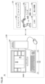
- FIG. 3 is a diagram showing the GUI configuration of the experiment protocol design application 500.
- the experiment protocol design application 500 includes a cue list window 510, a protocol list window 520, a protocol design window 530, an automated experiment system window 540, a sample vessel window 550, and a tool window 560. , a selection cursor Cr.
- the queue list window 510 displays queues in which multiple protocols are ordered. In FIG. 3 , queues q1 and q2 are displayed in queue list window 510 .
- the protocol list window 520 displays experimental protocols. In FIG. 3, experimental protocol p1 is displayed in protocol list window 520 and is selected.
- the experimental protocol is designed as a directed graph.
- connections between multiple nodes are defined as edges.
- a directed graph is stored as graph structure data according to a predetermined structured data format. Examples of structured data formats include XML (Extensible Markup Language) and Json (JavaScript (registered trademark) Object Notation).
- a plurality of nodes that can be selected as vertices of the directed graph are formed as a GUI and include container nodes, process nodes and data nodes.
- a container node is a node corresponding to a container containing a sample.
- a processing node is a node corresponding to each processing of the devices included in the automatic experiment system.
- a data node is a node corresponding to the output data of the processing of the experimental device.
- a protocol design window 530 is divided into a container area 531 , a processing area 532 and a data area 533 .
- the processing area 532 includes a start node Ms representing the start of the experimental protocol, an end node Me representing the end of the experimental protocol, and an edge E10 extending from the start node Ms to the end node Me. is displayed.
- the automated experiment system window 540 displays processes executable by each of at least one experimental device included in the automated experiment system selected by the user.
- the automatic experiment system 1 is selected.
- “conveyance of container” is displayed as a process that can be executed by the robot arm 121 .
- Cell culture is displayed as a process that can be executed by the incubator 122 .
- “Liquid Dispensing” is displayed as a process executable by the liquid handler 123 .
- “Absorptivity measurement” and “Fluorescence intensity measurement” are displayed as processing that can be executed by the microplate reader 124 .
- “Centrifugation” is displayed as a process executable by the centrifuge 125 .
- “Mass Spectrometry” is displayed as a process that can be performed by the LCMS 126 .
- the sample container window 550 displays the container containing the sample.
- plates Plt1 and Plt2 are displayed as containers containing E. coli, which is an example of a sample.
- the tool window 560 displays specific processing performed by the controller 110 of the automated experiment system 1.
- “feature quantity extraction” corresponds to a process of extracting a feature amount specified by the user from data corresponding to a data node selected by the user.
- “Conditional branching” corresponds to processing for branching based on the success or failure of a condition specified by the user.
- “Repeat” corresponds to repeating a specified process a number of times specified by the user.
- a “timer” corresponds to waiting for the experimental protocol to proceed for a period of time specified by the user.
- FIG. 4 is a diagram showing how a certain process is selected in the automatic experiment system window 540.
- FIG. 4 the user selects "Absorbance Measurement" in the automated experiment system window 540 and drags it between the start node Ms and the end node Me.
- FIG. 5 is a diagram showing how a processing node corresponding to the selected processing has been added to the protocol design window 530.
- FIG. 5 a processing node M1 corresponding to "absorbance measurement" has been added and selected between the start node Ms and the end node Me. With the addition of processing node M1, container node C1 and data node D1 are automatically added to container area 531 and data area 533, respectively.
- an information window 570 containing information about the selected node is displayed.
- a measurement wavelength and a well to be measured are displayed as absorbance measurement parameters corresponding to the processing node M1.
- the start node Ms and the processing node M1 are connected by an edge E1 from the start node Ms toward the processing node M1.
- the processing node M1 and the end node Me are connected by an edge E2 extending from the processing node M1 to the end node Me.
- Container node C1 and processing node M1 are connected by an edge E3 (first edge) extending from container node C1 to processing node M1.
- Processing node M1 and data node D1 are connected by an edge E4 (second edge) extending from processing node M1 to data node D1.
- Edge E3 indicates that the container corresponding to container node C1 is input to the process corresponding to processing node M1.
- Edge E4 indicates that the output data of the process corresponding to processing node M1 corresponds to data node D1.
- the user can design the experiment protocol in a directed graph by selecting the necessary processing from the window provided by the experiment protocol design application 500.
- a design example of an experimental protocol created by the user in the form of a directed graph is presented.
- FIG. 6 is a diagram showing a directed graph DG1, which is a design example of an experimental protocol.
- Protocol design window 530 shows directed graph DG1.
- the directed graph DG1 includes a start node Ms, an end node Me, processing nodes M11, M12, M13, M14, M15, M16, container nodes C11, C12, C13, C14, C15, C16, C17, C18, and data nodes D11, D12. including.
- the processing nodes M11 and M12 correspond to "liquid dispensing".
- the processing node M13 corresponds to "capture into culture apparatus”.
- Processing node M14 corresponds to "absorbance measurement”.
- Processing node M15 corresponds to "centrifuge”.
- Processing node M16 corresponds to "LCMS Analysis”.
- the container nodes C11 and C16 correspond to "culture plate”.
- Container nodes C12, C13, C17 and C18 correspond to "measurement plate 1”.
- Container nodes C14 and C15 correspond to "measurement plate 2”.
- the data node D11 corresponds to "absorbance data”.
- Data node D12 corresponds to "LCMS data”.
- Each node is connected to other nodes by edges.
- the start node Ms is connected to node M11 by an edge.
- Nodes C11 and C12 are connected to node M11 by edges.
- Node M11 is connected to node M12 by an edge.
- node M11 is connected to node C16 by an edge.
- the edges from the container nodes C11 and C12 toward the processing node M11 indicate that the culture plate and the measurement plate 1 are transported to predetermined positions, so that "liquid dispensing" corresponding to the processing node M11 is performed. show.
- An edge from the processing node M14 to the data node D11 indicates that absorbance data is obtained by absorbance measurement.
- the user can use the name of the plate to be transported as the container node and the data obtained by the experiment protocol as the data node.
- the user can intuitively create a directed graph imagining the flow of an actual experimental protocol.
- a user can create such a directed graph using the terminal device 400 .
- the server device 200 stores the directed graph created by the terminal device 400 .
- the server device 200 transmits the saved directed graph to the control device 110 of the experiment system 1 .
- a directed graph that includes container nodes and data nodes has the advantage that humans can intuitively understand the flow of the actual experimental protocol when they see it. However, this directed graph does not depict the motion of the robot arm 121 that transports the plate. In order to automatically execute an experiment protocol based on a directed graph in the experiment system 1, the motion of the robot arm 121 needs to be identified as a node. Therefore, upon receiving the directed graph, the control device 110 converts the directed graph including container nodes and data nodes into a directed graph including action nodes of the robot arm 121 .
- FIG. 7 is a diagram showing a directed graph DG2 including action nodes of the robot arm 121.
- the control device 110 converts the directed graph DG1 (see FIG. 6) created by the user into the directed graph DG2 shown in FIG.
- the directed graph DG2 includes nodes R11 to R14 corresponding to the action nodes of the robot arm 121.
- FIG. Nodes R11-R14 are the container nodes C11-C18 shown in FIG.
- node R11 includes the processing of node C11 regarding the culture plate and the processing of node C12 regarding measurement plate 1.
- Node R12 includes node C13 processing for measurement plate 1, node C14 processing for plate 2, and node C16 processing for culture plate.
- Node R13 includes the processing of node C15 regarding measurement plate 2 and the processing of node C17 regarding measurement plate 1 .
- Node R14 includes the processing of node C18 for measurement plate one.
- control device 110 converts a directed graph containing container nodes and data nodes into a directed graph containing action nodes of the robot arm 121 .
- action nodes R11 to R14 of the directed graph DG2 shown in FIG. 7 the description of the information on the plate conveyed by the robot arm 121 and the conveying destination device is omitted for the sake of simplicity. These pieces of information are included in the action nodes of the directed graph that are actually used.
- the user can easily design an experiment protocol using a directed graph.
- the user can relatively easily design a complicated experimental protocol including parallel processing by creating the experimental protocol as a directed graph.
- a directed graph containing container nodes and data nodes is converted into a directed graph containing action nodes of the robot arm 121 . Therefore, the user can create a directed graph as illustrated in FIG.
- the efficiency of experiments can be improved by simultaneously processing multiple nodes according to the directed graph.
- the node M12 and the node M13 are processed in parallel after the processing of the node R12 is completed, and the processing of the node R13 is executed after the processing of both nodes M12 and M13 is completed. stipulated.
- control device 110 executes an experimental protocol that includes parallel processing.
- a controller 110 configured to wait for the processing of one node to complete before commanding the processing of the next node cannot manage the processing of multiple nodes proceeding in parallel.
- experiment execution software experiment work was performed sequentially by sequentially operating each device.
- the experiment execution software will give instructions to other devices after receiving the completion of the operation corresponding to the instructions from the device that gave the instructions.
- control device 110 can automatically execute an experimental protocol created in a directed graph without forcing the user to perform the design work described above. Specifically, control device 110 generates an event handler and an adjacency matrix list based on the directed graph. Event handlers and adjacency matrix lists are data that controller 110 uses to drive experiments based on directed graphs.
- FIG. 8 is a diagram showing a directed graph DG3.
- the event handler and the adjacency matrix list will be explained using a directed graph DG3 with a small number of nodes.
- the directed graph DG3 is composed of nodes A to F in addition to a start node and an end node.
- Nodes A through F are various processing nodes including, for example, the action node of robot arm 121 shown in FIG. In FIG. 8, these processing nodes are represented by the concept of AF.
- node B and node C need to be processed in parallel.
- the processing of node B and node C should be performed quickly after the processing of node A is completed.
- the process of node D must be executed after the processes of nodes B and C are completed, and the process of node F is executed after the processes of nodes D and E are completed.
- the processing of node D needs to be executed immediately after the processing of nodes B and C is completed.
- controller 110 it is not easy for controller 110 to accurately predict when node B and node C will complete processing.
- the processing of node F must be executed immediately after the processing of nodes D and E is completed.
- control device 110 it is not easy for control device 110 to accurately predict when the processing of nodes D and E will be completed. Appropriate control in consideration of such experimental efficiency is required for the controller 110 .
- node D and node E need to be processed in parallel.
- the control device 110 is required to perform more complicated control than when realizing the parallel processing of the nodes B and C.
- the control device 110 controls the order and start timing of processing of each node with event handlers and adjacency matrix lists. Next, an example of an event handler and an adjacency matrix list will be given to explain each.
- FIG. 9 is a diagram showing event handlers created by the control device 110 based on the directed graph DG3.
- FIG. 10 is a diagram showing an adjacency matrix list created by control device 110 based on directed graph DG3.
- Controller 110 generates an adjacency matrix and event handlers based on the experimental protocol to execute the received experimental protocol. Controller 110 utilizes event handlers and adjacency matrix lists to execute experimental protocols. By utilizing event handlers and adjacency matrix lists, controller 110 can execute experimental protocols designed in the form of directed graphs.
- event handlers are configured by combining nodes of directed graph D3 and statuses.
- An event handler is data indicating the status of node processing.
- the event handler thus acts as a status list.
- “To do” means that the process of the corresponding node is waiting for execution.
- the status of all nodes is "To do”. Therefore, the event handler in FIG. 9 indicates that all node processes are waiting to be executed.
- a state in which all node processes are waiting to be executed is called an initial state.
- Control device 110 generates an event handler and an adjacency matrix list corresponding to the initial state based on directed graph D3.
- the adjacency matrix list is composed of data in matrix form in which all nodes of the directed graph D3 are expanded in two directions, the X-axis direction and the Y-axis direction.
- x is added to the node names aligned in the X-axis direction
- y is added to the node names aligned in the Y-axis direction.
- the adjacency matrix list includes start x columns, Ax columns, Bx columns, Cx columns, and so on, as well as start y rows, Ay rows, By rows, Cy rows, and so on.
- the start x row, Ax row, Bx row, Cx row, . . . are also expressed as Column1, Column2, Column3, Column4, .
- component values representing the state of the node are set. For example, "wait" is set as an example of the component value representing the state of the node at the position specified by the Bx column and the Ay row in FIG.
- positions specified by Bx columns and Ay rows are described in a coordinate system using the X and Y axes, such as (Bx, Ay).
- the adjacency matrix list shown in FIG. 10 is a list corresponding to the initial state. Whether or not the processing of a node can be executed is determined by the component values in the node name column.
- a state in which node processing can be executed means that processing of other nodes necessary for executing the processing of the node has been completed.
- the control device 110 updates the component value of the row corresponding to the node name from “wait” to "ready". For example, when node A completes processing, all component values present in row Ay are updated from “wait” to “ready.” As a result, the component values of (Bx, By) and (Cx, Ay) are updated from “wait” to "ready.”
- the trigger for updating the component value from “wait” to “ready” is the completion of node processing.
- the target to be updated from “wait” to “ready” is the component value of the row corresponding to the node name for which processing has been completed.
- the control device 110 checks the column corresponding to a node in order to determine whether it is possible to execute the processing of that node. If even one component value of "wait" exists in the column corresponding to that node, the control device 110 determines that the process of the node corresponding to that column is not executable. If there is not even a single "wait" component value in the column corresponding to that node, control device 110 determines that the node corresponding to that column can be processed. For example, from the state of the adjacency matrix list shown in FIG. 10, the processing of the node ready to be executed is only the processing of the start node. While there is no "wait" component value in the start x column. This is because there is at least one component value of "wait” in other columns.
- the control device 110 itself receives a command to start the processing of the start node issued by itself and generates a completion signal of the processing of the start node. This immediately completes the processing of the start node.
- the controller 110 updates the component value of the start y row corresponding to the start node from "wait" to "ready". As a result, the component value of (Ax, start y) changes to "ready”. Then, the component value of "wait” does not exist in the Ax column.
- node A is waiting for execution of processing. From the state of the event handler and the adjacency matrix list, it is specified that node A is ready to process.
- the control device 110 starts the processing of node A and updates the component value of the Ax column from “ready” to “passed” in the adjacency matrix list. As a result, the component value of (Ax, start y) changes to "passed".
- the trigger for updating the component value from “ready” to “passed” is the completion of node processing.
- the target to be updated from “ready” to “passed” is the component value of the column corresponding to the node name where the process started.
- FIG. 11 is a diagram showing how the event handler is updated according to the progress of processing based on the directed graph DG3.
- FIG. 12 is a diagram showing how the adjacency matrix list is updated according to the progress of processing based on the directed graph DG3.
- the state in which the processing of the start node, node A, and node C in the directed graph D3 is completed and the processing of node B is being executed is taken as an example. Describe the corresponding event handlers and adjacency matrix lists.
- the state of node processing in directed graph D3 is reflected in the event handler. As shown in FIG. 11, the status corresponding to the start node, node A, and node C becomes "Done”, and the status corresponding to node B becomes "Run”. The statuses corresponding to node D, node E, node F, and end nodes waiting to be processed are "To do”.
- the component values of columns Ax, Bx, and Cx are "passed." These component values mean that node A, node B, and node C are not pending.
- Controller 110 identifies these states by referencing the event handler and adjacency matrix list.
- control device 110 changes the status of the event handler corresponding to node B from "Run” to "Done". Further, when the processing of node B is completed, the control device 110 changes the two “wait”s in the By row of the adjacency matrix list to “ready”. This eliminates "wait” in the Dx and Ex columns. At this time, control device 110 can determine that node D and node E are ready to run. Control device 110 starts the processing of node D and node E, and changes the status of node D and node E of the event handler from "To do” to "Run”. Further, control device 110 changes "ready” in Dx and Ex columns of the adjacency matrix list to "passed”.
- the control device 110 generates an adjacency matrix list in which the connections between nodes in the experimental protocol are represented by matrix elements, and changes the values of the elements of the adjacency matrix list to process the nodes.
- Manage when to run When the control device 110 completes the processing of all dependent nodes in the adjacency matrix list, it commands the processing of the next node.
- One node basically consists of instructions having information on operating conditions of one device.
- a command corresponding to that node is transmitted from the control device 110 to the target device.
- the control device 110 receives a completion signal indicating the completion of the operation from the device that sent the command, it determines whether the processing corresponding to the node has been completed.
- the control device 110 may output the latest event handler and adjacency matrix list to the terminal device 400 while executing the automatic experiment.
- Terminal device 400 may display the input event handler and adjacency matrix list on the display device.
- control device 110 generates an event handler and an adjacency matrix list based on the directed graph.
- Controller 110 executes experimental protocols designed by directed graphs based on event handlers and adjacency matrix lists.
- FIG. 13 is a flowchart explaining the flow of automatic experiments based on the experiment protocol.
- the terminal device 400 designs an experiment protocol in a directed graph based on the user's operation, and transmits the experiment protocol to the server device 200 (step S11).
- the server device 200 transmits the experiment protocol to the automatic experiment system 1 according to the user's operation (step S12).
- the control device 110 of the automatic experiment system 1 automatically executes the experiment protocol received from the server device 200 (step S13).
- the control device 110 transmits output data of processing included in the experiment protocol to the server device 200 (step S14).
- the case where the experiment protocol designed in the terminal device 400 is transmitted to the automatic experiment system 1 via the server device 200 has been described.
- the terminal device 400 may directly transmit the experiment protocol to the automated experiment system 1 .
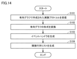
- FIG. 14 is a flow chart showing processing by which the control device 110 generates an event handler and an adjacency matrix list according to the experiment protocol.
- control device 110 receives an experiment protocol created as a directed graph (step S101).
- An experiment protocol created as a directed graph is transmitted from server device 200 to control device 110 .
- control device 110 converts the format of the received directed graph (step S102). Specifically, the control device 110 converts the directed graph format so that the received directed graph includes the action nodes of the robot arm 121 . As a result, for example, the directed graph shown in FIG. 6 is converted into the directed graph shown in FIG.
- control device 110 generates an event handler and an adjacency matrix list based on the converted directed graph (steps S103 and S104), and ends the processing based on this flowchart. For example, control device 110 generates the event handler shown in FIG. 9 and the adjacency matrix list shown in FIG. 10 based on the directed graph shown in FIG.
- FIG. 15 is a flow chart showing the process by which the control device 110 executes the experiment protocol based on the event handler and the adjacency matrix list.
- the control device 110 sets the variable Column to 1 (step S111).
- Column corresponds to the column number of the adjacency matrix list shown in FIG.
- the Column set to 1 in step S111 corresponds to the start x column shown in FIG.
- control device 110 searches for data in the column corresponding to Column in the adjacency matrix list (step S112).
- the control device 110 determines whether or not "wait” exists in the column corresponding to Column (step S113). If "wait” does not exist in the column corresponding to Column, control device 110 advances to the process of step S118 and updates the value of Column. This updates the value of Column from 1 to 2, for example.
- step S113 determines in step S113 that "wait” does not exist in the column corresponding to Column, it determines in the event handler whether the status of the node corresponding to Column is "To do” (step S114). Thereby, the control device 110 confirms that the node corresponding to Column is the processing target and is waiting for execution.
- step S114 determines in step S114 that the status of the node corresponding to Column is not "To do”
- the process proceeds to step S118. If the control device 110 determines in step S114 that the status of the node corresponding to the Column is "To do”, it changes the status of the node of the event handler corresponding to the Column from "To do” to "Run”. (Step S115). As a result, the control device 110 selects a node for newly starting processing. Next, the control device 110 changes all "ready” in the column corresponding to Column to "passed” (step S116).
- step S117 the control device 110 instructs the device corresponding to the processing of the node to operate.
- step S117 the process corresponding to the node whose status has been changed to "Run" in step S115 is executed.
- Equipment corresponding to node processing includes, for example, a robot arm 121, an incubator 122, a liquid handler 123, a microplate reader 124, a centrifuge 125, and a liquid chromatograph mass spectrometer 126. These devices receive operation instructions from the control device 110 in step S117 according to the processing of the node. These devices realize the processing included in the experimental protocol by performing actions according to instructions. These devices transmit a completion signal indicating the completion of the operation to the control device 110 when the operation according to the instruction is completed.
- Devices corresponding to node processing further include a control device 110 .
- the control device 110 executes node processing corresponding to “feature value extraction” and the like in addition to the processing of the start node and the end node.
- the control device 110 realizes the processing included in the experiment protocol by executing the operation according to its own instructions. When the control device 110 completes the operation according to the instruction, it returns to itself a completion signal indicating the completion of the operation.
- control device 110 updates the value of Column (step S118).
- control device 110 determines whether or not a completion signal has been received from any device (step S119). If the control device 110 does not receive the completion signal, the process proceeds to step S122. When receiving the completion signal, control device 110 changes the status of the node corresponding to the completed process from "Run” to "Done” in the event handler (step S120).
- control device 110 changes all "wait” in the row corresponding to the node of the completed process to "ready” (step S121). For example, when the processing of node B ends, in the adjacency matrix list shown in FIG. 10, two “wait”s in the By row are changed to "ready”.
- control device 110 outputs a display signal for displaying the event handler and the adjacency matrix list (step S122).
- the user may notify the control device 110 in advance of the output destination of the display signal.
- control device 110 outputs a display signal of the event handler and the adjacency matrix list to the notified output destination. For example, if a display device is connected to control device 110, control device 110 may output a display signal to the display device. As a result, the event handler and the adjacency matrix list are displayed on the display device.
- the control device 110 may output a display signal to the terminal device 400.
- terminal device 400 displays the event handler and the adjacency matrix list on the screen of the display device.
- the user can see the latest state of the event handler and adjacency matrix list on the screen. Therefore, the user can easily grasp the progress of the automatic experiment.
- control device 110 determines whether all the event handler statuses are "Done” (step S123). If the status of all event handlers is not "Done”, there is unexecuted node processing. Therefore, in this case, the control device 110 returns to step S112 and repeats the process. When the control device 110 determines that the statuses of all event handlers are "Done”, it determines that all the processing of the planned experimental protocol has been completed, and terminates the processing based on this flowchart.
- the control device 110 uses the event handler and the adjacency matrix list to execute the experiment protocol based on the directed graph according to the procedure described above. Therefore, the control device 110 can appropriately control parallel processing of a plurality of nodes included in the directed graph DG3 (see FIG. 8). The control device 110 can also appropriately control the processing of nodes such as the nodes D and F included in the directed graph DG3 that need to be started after the processing of a plurality of nodes is completed. As a result, according to the control device 110, it is possible to increase the efficiency of the experiment based on the experiment protocol created by the directed graph.
- FIG. 16 is a block diagram showing the configuration of the automatic experiment management system 1000 for explaining the configuration related to the functions of the control device 110.
- the processing of the control device 110 described based on the flowchart will be described here as the function of the control device 110 .
- the control device 110 includes an input unit 113, a generation unit 114, a selection unit 115, a command unit 116, an update unit 117, an output unit 118, and a conversion unit 119, as shown in FIG.
- These configurations are implemented by processor 111 and memory 112 of control device 110 shown in FIG.
- the input unit 113 accepts input of an experimental protocol designed as a directed graph containing multiple nodes corresponding to experimental processing.
- the generation unit 114 generates an adjacency matrix list and the like.
- the selection unit 115 selects a node to start processing from among the plurality of nodes based on an adjacency matrix list or the like.
- the instruction unit 116 instructs various experimental devices to process the node selected by the selection unit 115 .
- the update unit 117 updates the adjacency matrix list and the like when one of the processes of the plurality of nodes is completed.
- the output unit 118 outputs a signal for displaying an adjacency matrix list or the like.
- the conversion unit 119 converts the experiment protocol input to the input unit 113 into a container. Convert to a second directed graph containing the motions of the moving device.
- FIG. 17 is a block diagram showing the hardware configuration of the server device 200.
- server device 200 includes processor 201 , memory 202 and hard disk 203 as storage units, communication interface 204 as communication unit, and input/output unit 205 . These are communicatively connected to each other via a bus 210 .
- the hard disk 203 is a non-volatile storage device.
- the hard disk 203 stores, for example, an operating system (OS) program 51 and an automatic experiment management program 52 .
- the hard disk 203 stores, for example, settings and outputs of various applications.
- the memory 202 is a volatile storage device and includes, for example, a DRAM (Dynamic Random Access Memory).
- the processor 201 includes a CPU (Central Processing Unit).
- the processor 201 loads a program stored in the hard disk 203 into the memory 202 and executes it to implement various functions of the server device 200 .
- processor 201 running automated experiment management program 52 provides experiment protocol design application 500 to terminal device 400 .
- Processor 201 connects to network NW via communication interface 204 .
- FIG. 18 is a block diagram showing the configuration of an automatic experiment management system 1100 according to Modification 1 of the embodiment.
- the configuration of the automatic experiment management system 1100 is obtained by removing the server device 200 and the database 300 from the automatic experiment management system 1000 of FIG. 1 and replacing the terminal device 400 with 400A. Since they are the same except for these, the description will not be repeated.
- An experiment protocol design application 500A is displayed on the display 431 of the terminal device 400A.
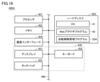
- FIG. 19 is a block diagram showing the hardware configuration of a terminal device 400A related to Modification 1.
- the terminal device 400A has a configuration in which an automatic experiment management program 52A is added to the hard disk 423 of FIG. Since the rest is the same, the description will not be repeated.
- an automatic experiment management program 52A By executing the automatic experiment management program 52A by the processor 421, automatic execution of the experiment protocol by the experiment protocol design application 500A and the automatic experiment system is realized.
- FIG. 20 is a block diagram showing the configuration of an automatic experiment system 1B according to Modification 2. As shown in FIG. The configuration of the automatic experiment system 1B is a configuration in which the controller 110 is replaced with 110B in the automatic experiment system 1 of FIG. Other than this, they are the same, so the description will not be repeated.
- the control device 110B includes an input/output unit 130 and a computer 140 (processing unit).
- the input/output unit 130 includes a display 131 (display unit), a keyboard 132 (input unit), and a mouse 133 (input unit).
- Display 131 , keyboard 132 and mouse 133 are connected to computer 140 .
- Display 131 displays the GUI of experiment protocol design application 500B.
- the keyboard 132 and mouse 133 accept GUI operations for the experiment protocol design application 500B by the user. That is, the user performs desired GUI operations on the experiment protocol design application 500B by operating the keyboard 132 or the mouse 133 while referring to the display on the display 131 .
- FIG. 21 is a block diagram showing the hardware configuration of the control device 110B.
- computer 140 includes processor 141 , memory 142 and hard disk 143 as storage units, and communication interface 144 . These are communicatively connected to each other via a bus 145 .
- the hard disk 143 is a non-volatile storage device.
- the hard disk 143 stores, for example, an operating system (OS) program 61 and an automatic experiment management program 52B.
- OS operating system
- hard disk 143 stores, for example, settings and outputs of various applications.
- the memory 142 is a volatile storage device and includes, for example, a DRAM (Dynamic Random Access Memory).
- the processor 141 includes a CPU (Central Processing Unit).
- the processor 141 loads a program stored in the hard disk 143 into the memory 142 and executes it.
- the processor 141 executes the automatic experiment management program 52B by the processor 141, automatic execution of the experiment protocol by the experiment protocol design application 500B and the plurality of experimental devices 120 is realized.
- Processor 141 connects to a network via communication interface 144 .
- FIG. 22 is a diagram showing a directed graph DG4.
- the terminal device 400 can be used to create directed graphs in various formats.
- nodes are identified using device names.
- a node LH1 indicates the first processing by the liquid handler 123.
- Liquid handler 123 for example, dispenses samples.
- Node LH2 indicates the second processing by liquid handler 123.
- FIG. INC indicates processing by the incubator 122 .
- the incubator 122 cultures cells, for example.
- PR indicates processing by the microplate reader 124;
- Microplate reader 124 measures, for example, optical properties of samples in microplates.
- CEN indicates processing by centrifuge 125 .
- LCMS indicates processing by liquid chromatograph mass spectrometer 126 .
- FIG. 23 is a diagram showing a directed graph DG4 and a directed graph DG5 obtained by adding a node of the robot arm 121 to the directed graph DG4.
- the control device 110 may be configured so as to convert the directed graph DG4 into a directed graph DG5 to which the node of the robot arm 121 is added.
- the experiment is automatically advanced by the control device 110 based on the experiment protocol in the form of a directed graph created by the user. Therefore, according to the present embodiment, it is possible to execute an experiment protocol having a graph structure as it is in the automatic experiment system 1 with a lightweight implementation.
- devices involved in the experiment are controlled according to the experimental protocol of the visualized graph structure. Therefore, the user can easily create a complicated experiment protocol including parallel processing without considering the time required for the operation of the devices that operate in parallel, the timing of the completion of the operation, the timing of the start of the next operation, and so on. can. Also, since the experiment is executed based on the experiment protocol including parallel processing, the efficiency of the experiment can be improved.
- the user can create an easy-to-understand protocol corresponding to the operation of the device that the user understands. Become.
- the user may express the LCMS autoloader, batch file load, and batch start operation commands in one LCMS node.
- the user can create an experiment protocol by omitting the operation of the robot arm 121 that transports the sample.
- the user can use a node corresponding to the plate containing the sample, a node corresponding to the destination of the plate, and a node corresponding to the origin of the plate instead of the nodes for the operation of the robot arm 121.
- a user can create an experiment protocol more intuitively by connecting those nodes with edges so as to correspond to the processing flow of the experiment protocol (see FIG. 6).
- an experiment can proceed based on a directed graph including parallel processing by using an adjacency matrix list representing node dependencies.
- the types of statuses that can be set in event handlers may be reduced. For example, among “To do”, “Run”, and “Done”, the event handler may be updated without using “Run”. Even if "Run” is not used, the control device 110 determines whether the processing of the target node needs to be executed or whether the processing of the target node has already been executed by "To do” and "Done". can determine if there is
- control device 110 can determine whether or not it is possible to execute the processing of the target node by "wait” and "passed.”
- An event handler function may be provided in the adjacency matrix list.
- the adjacency matrix list may be provided with component values indicating whether the node is waiting to be executed, is being executed, or has been executed.
- the control device 110 may output at least one of the event handler and the adjacency matrix list to the outside via a communication network such as the Internet.
- a communication network such as the Internet.
- the nodes included in the directed graph hold information such as the device to be operated, the processing of the device to be operated, and the operating conditions. If the experimental protocol includes a first command to operate the device when the first condition is satisfied and a second command to operate the device when the second condition is satisfied, the first command and the second command include It is desirable that the first and second instructions be created by the user as separate nodes, even if the devices that operate based on them are the same.
- samples are prepared, adjusted, and analyzed by moving the samples between various devices by the robotic arm 121 .
- samples can be represented as nodes, and relationships between moving devices can be represented as edges.
- the user can create a directed graph by omitting nodes for the motion of the robot arm 121 .
- terminal device 400 may provide a system environment in which a user can create such a directed graph.
- connecting the first node and the second node with an edge, and connecting the first node and the third node with an edge to express an instruction for parallel processing of the second node and the third node. can be done.
- different devices need to be set for the device that operates corresponding to the second node and the device that operates for the third node. Therefore, if the device specified by the user for the second node and the device specified for the third node are the same device, it is desirable to configure the terminal device 400 so as not to accept the user's specification.
- the terminal device 400 may accept such user designation. Further, it is desirable to configure the terminal device 400 so as not to accept the user's designation when the sample designated by the user for the second node and the sample designated for the third node are the same. Of course, if the processing order of the processing of the second node and the processing of the third node is clearly defined, the terminal device 400 may accept the designation.
- each experimental device may independently manage statuses such as Ready/Busy, Available/Locked, and method queues.
- a plurality of sets of instructions containing information on the operating conditions of one device and information on the operating conditions of the plurality of devices are configured as one node.
- an experimental protocol may be designed such that each robot arm 121 advances processing in parallel. This makes it possible, for example, to create an experimental protocol in which each robot arm 121 simultaneously transports a sample.
- the motion of the robot arms 121 may be represented by nodes.
- the node of the robot arm 121 may be adopted as the node of the device instead of the node corresponding to the operation of the robot arm 121 .
- the node of the robot arm 121 is omitted. If there is only one robot arm 121 in the system, the action node of the robot arm 121 may be inserted immediately before the node of each device other than the robot arm 121 . In this case, the operation node of the robot arm 121 may sequentially include the operation of loading the sample into each device or the operation of unloading the sample from each device.
- a node for the operation of the robot arm 121 When executing processes of multiple nodes in parallel, insert a node for the operation of the robot arm 121 immediately before or after the multiple nodes to be operated in parallel. For example, in directed graph DG5 shown in FIG. 23, an RB node is inserted immediately before an LH2 node and an INC node that are operated in parallel. Also, the terminal device 400 may be restricted so that only the number of parallel processes corresponding to the number of the robot arms 121 can be designed.
- a control device is a control device that controls an experimental device based on an experimental protocol.
- the control device includes an input unit that receives input of an experiment protocol designed as a directed graph including a plurality of nodes corresponding to the processing of the experiment, and a first node and a second node that becomes executable upon completion of the processing of the first node.
- a generator for generating a dependency list including first dependency information indicating that the start of the process of the second node depends on the completion of the process of the first node when included in the plurality of nodes; a selection unit that selects a node to start processing from based on the dependency list, a command unit that commands the experimental device to process the node selected by the selection unit, and one of the processing of a plurality of nodes is completed an updating unit for updating the dependency list or the states of the plurality of nodes when the processing is completed, and the selecting unit selects the second node when the processing of the first node is completed.
- the update unit updates the first dependency information from the first information to the second information when the processing of the first node is completed, and the selection unit updates the first dependency information to the second information. 1. If the dependency information is updated from the first information to the second information, select the second node.
- the generation unit further generates a status list for specifying the status of each of the plurality of nodes, and the update unit performs If so, update the status of the first node in the status list from running to completed, and update the status of the second node in the status list from waiting to run to running if the second node starts processing.
- control device described in paragraph 3 it is possible to proceed with processing while specifying the status of each of the plurality of nodes based on the status list.
- the plurality of nodes includes a third node that becomes executable upon completion of the processing of the first node, and the dependency list includes the start of processing of the third node. includes second dependency information indicating that depends on the completion of the processing of the first node, and the updating unit updates the first dependency information and the second dependency information from the first information to the second dependency information when the processing of the first node is completed. 2 information, and the selection unit selects the second node and the third node when the first dependency information and the second dependency information are updated from the first information to the second information.
- the processing of the second node and the processing of the third node can be executed in parallel.
- the plurality of nodes includes a fourth node capable of starting processing after the processing of the second node and the third node is completed, and
- the relationship list includes third dependency information indicating that the start of the process of the fourth node depends on the completion of the process of the second node, and that the start of the process of the fourth node depends on the completion of the process of the third node.
- the update unit updates the third dependency information from the first information to the second information when the processing of the second node is completed, and when the processing of the third node is completed,
- the fourth dependency information is updated from the first information to the second information, and the selection unit selects the fourth node when the third dependency information and the fourth dependency information are updated from the first information to the second information.
- the process of the fourth node can be executed at the timing when the processes of the second node and the third node executed in parallel are completed.
- the user can grasp the progress of the experiment protocol by checking the displayed dependency list.
- the experiment protocol input to the input unit is designed with a first directed graph including nodes corresponding to containers containing samples. If so, the conversion unit converts the experiment protocol input to the input unit into a second directed graph including the operation of the device that moves the container, and the generation unit generates a dependency list based on the second directed graph. Generate.
- the experiment proceeds based on the first directed graph intuitively created by the user using the nodes corresponding to the containers containing the samples. Therefore, the user can create an experiment protocol more easily.
- a method is a method of controlling an experimental device based on an experimental protocol.
- the method comprises the steps of accepting input of an experiment protocol designed as a directed graph including a plurality of nodes corresponding to operations of the experiment; generating a dependency list including first dependency information indicating that, if included in the node, the start of processing of the second node depends on the completion of processing of the first node; selecting a node to be started based on the dependency list; instructing the experimental device to process the node selected by the selector; Updating the relationship list or states of the plurality of nodes, and selecting a node to start processing selects a second node when processing of the first node is complete.
- 1, 1B automatic experiment system 110, 110B control device, 111 processor, 112 memory, 113 input unit, 114 generation unit, 115 selection unit, 116 command unit, 117 update unit, 118 output unit, 119 conversion unit, 120 experiment equipment , 121 robot arm, 122 incubator, 123 liquid handler, 124 microplate reader, 125 centrifuge, 130, 205, 430 input/output unit, 131, 431 display, 132, 432 keyboard, 133 mouse, 140 computer, 141, 201 , 421 processor, 142, 202, 422 memory, 143, 203, 423 hard disk, 144, 204, 424 communication interface, 145, 210, 440 bus, 200 server device, 300 database, 400, 400A terminal device, 433 touch pad, 500, 500A, 500B Experiment protocol design application, 510 Cue list window, 520 Protocol list window, 530 Protocol design window, 531 Container area, 532 Processing area, 533 Data area, 540 Automatic experiment system window, 550 Sample container window
Landscapes
- Engineering & Computer Science (AREA)
- Physics & Mathematics (AREA)
- General Physics & Mathematics (AREA)
- General Engineering & Computer Science (AREA)
- Automation & Control Theory (AREA)
- Life Sciences & Earth Sciences (AREA)
- Health & Medical Sciences (AREA)
- Chemical & Material Sciences (AREA)
- Analytical Chemistry (AREA)
- Biochemistry (AREA)
- General Health & Medical Sciences (AREA)
- Immunology (AREA)
- Pathology (AREA)
- Automatic Analysis And Handling Materials Therefor (AREA)
- Management, Administration, Business Operations System, And Electronic Commerce (AREA)
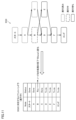
Priority Applications (3)
| Application Number | Priority Date | Filing Date | Title |
|---|---|---|---|
| JP2023552756A JP7622865B2 (ja) | 2021-10-06 | 2022-09-06 | 制御装置および方法 |
| CN202280065135.9A CN118019986A (zh) | 2021-10-06 | 2022-09-06 | 控制装置及方法 |
| US18/697,649 US20250093831A1 (en) | 2021-10-06 | 2022-09-06 | Controller and Method |
Applications Claiming Priority (2)
| Application Number | Priority Date | Filing Date | Title |
|---|---|---|---|
| JP2021164631 | 2021-10-06 | ||
| JP2021-164631 | 2021-10-06 |
Publications (1)
| Publication Number | Publication Date |
|---|---|
| WO2023058384A1 true WO2023058384A1 (ja) | 2023-04-13 |
Family
ID=85804139
Family Applications (1)
| Application Number | Title | Priority Date | Filing Date |
|---|---|---|---|
| PCT/JP2022/033379 Ceased WO2023058384A1 (ja) | 2021-10-06 | 2022-09-06 | 制御装置および方法 |
Country Status (4)
| Country | Link |
|---|---|
| US (1) | US20250093831A1 (https=) |
| JP (1) | JP7622865B2 (https=) |
| CN (1) | CN118019986A (https=) |
| WO (1) | WO2023058384A1 (https=) |
Citations (7)
| Publication number | Priority date | Publication date | Assignee | Title |
|---|---|---|---|---|
| JP2008298798A (ja) * | 2001-11-07 | 2008-12-11 | Genvault Corp | 保管および分析のシステムおよび方法 |
| JP2009174997A (ja) * | 2008-01-24 | 2009-08-06 | Hitachi High-Technologies Corp | 自動分析装置 |
| JP2013077335A (ja) * | 2007-02-02 | 2013-04-25 | Beckman Coulter Inc | 検査室試験結果を自動検証するシステムおよび方法 |
| WO2020183428A2 (en) * | 2019-03-14 | 2020-09-17 | Tata Consultancy Services Limited | Method and system for mapping read sequences using a pangenome reference |
| WO2021005835A1 (ja) * | 2019-07-10 | 2021-01-14 | 株式会社日立ハイテク | 自動分析装置、および自動分析装置の運転方法 |
| WO2021038778A1 (ja) * | 2019-08-29 | 2021-03-04 | 株式会社島津製作所 | クロマトグラフ用オートサンプラ |
| WO2022004061A1 (ja) * | 2020-06-30 | 2022-01-06 | 株式会社島津製作所 | 実験プロトコルを設計する方法、システム、および装置 |
Family Cites Families (2)
| Publication number | Priority date | Publication date | Assignee | Title |
|---|---|---|---|---|
| CN109970624B (zh) | 2019-04-22 | 2020-05-22 | 上海旭东海普药业有限公司 | 氟哌啶醇的纯化方法 |
| CN110029900B (zh) | 2019-05-04 | 2024-05-10 | 清远市星徽精密制造有限公司 | 一种具有预紧调节功能的防变形铰链 |
-
2022
- 2022-09-06 US US18/697,649 patent/US20250093831A1/en active Pending
- 2022-09-06 CN CN202280065135.9A patent/CN118019986A/zh active Pending
- 2022-09-06 JP JP2023552756A patent/JP7622865B2/ja active Active
- 2022-09-06 WO PCT/JP2022/033379 patent/WO2023058384A1/ja not_active Ceased
Patent Citations (7)
| Publication number | Priority date | Publication date | Assignee | Title |
|---|---|---|---|---|
| JP2008298798A (ja) * | 2001-11-07 | 2008-12-11 | Genvault Corp | 保管および分析のシステムおよび方法 |
| JP2013077335A (ja) * | 2007-02-02 | 2013-04-25 | Beckman Coulter Inc | 検査室試験結果を自動検証するシステムおよび方法 |
| JP2009174997A (ja) * | 2008-01-24 | 2009-08-06 | Hitachi High-Technologies Corp | 自動分析装置 |
| WO2020183428A2 (en) * | 2019-03-14 | 2020-09-17 | Tata Consultancy Services Limited | Method and system for mapping read sequences using a pangenome reference |
| WO2021005835A1 (ja) * | 2019-07-10 | 2021-01-14 | 株式会社日立ハイテク | 自動分析装置、および自動分析装置の運転方法 |
| WO2021038778A1 (ja) * | 2019-08-29 | 2021-03-04 | 株式会社島津製作所 | クロマトグラフ用オートサンプラ |
| WO2022004061A1 (ja) * | 2020-06-30 | 2022-01-06 | 株式会社島津製作所 | 実験プロトコルを設計する方法、システム、および装置 |
Also Published As
| Publication number | Publication date |
|---|---|
| US20250093831A1 (en) | 2025-03-20 |
| CN118019986A (zh) | 2024-05-10 |
| JPWO2023058384A1 (https=) | 2023-04-13 |
| JP7622865B2 (ja) | 2025-01-28 |
Similar Documents
| Publication | Publication Date | Title |
|---|---|---|
| Janssen et al. | pyiron: An integrated development environment for computational materials science | |
| US7491367B2 (en) | System and method for providing a standardized state interface for instrumentation | |
| Fei et al. | AlabOS: a Python-based reconfigurable workflow management framework for autonomous laboratories | |
| JP7652314B2 (ja) | 実験プロトコルを設計する方法 | |
| Bhuvaneshwar et al. | A case study for cloud based high throughput analysis of NGS data using the globus genomics system | |
| EP3318974A2 (en) | Framework for developing and deploying applications | |
| CN108664314B (zh) | 大数据处理流程模块化管理方法及装置 | |
| JP7768239B2 (ja) | 実験プロトコルを管理する方法、システム、および装置 | |
| JP2008234024A (ja) | バッチ処理プログラム,バッチ処理方法及びバッチ処理装置 | |
| JP6869453B2 (ja) | 情報処理装置、情報処理方法及び情報処理プログラム | |
| WO2020214343A1 (en) | Automatic repetition of context-specific code edits | |
| KR20200078558A (ko) | 고 처리량 게놈 제조 작업을 계획하고 수행하기 위한 장치-애그노스틱 시스템 | |
| JP7622865B2 (ja) | 制御装置および方法 | |
| Ieong et al. | Progress towards automated Kepler scientific workflows for computer-aided drug discovery and molecular simulations | |
| JP2010282286A (ja) | 開発支援装置,プログラム | |
| EP3361329B1 (en) | Information processing apparatus, system, method and recording medium for generating a user interface | |
| CN105677331A (zh) | 一种任务执行方法和装置 | |
| EP3018576B1 (en) | A method for controlling changes in a computer system | |
| CN115803742A (zh) | 设计辅助系统、设计辅助方法及设计辅助程序 | |
| JP7687935B2 (ja) | 計算機システム及び装置条件の探索支援方法 | |
| JP2007011728A (ja) | 汎用計算機の操作手順作成装置及び方法、並びにプログラム | |
| CN115755793B (zh) | 自动化流程的操作配置方法、装置、电子设备及存储介质 | |
| CN120319357A (zh) | 材料合成装置、材料合成平台及操作材料合成装置的方法 | |
| Church et al. | Selected approaches and frameworks to carry out genomic data provision and analysis on the cloud | |
| Tran et al. | Training Artificial Intelligence Agents to Compress Web Page Actions into URL Rewrites |
Legal Events
| Date | Code | Title | Description |
|---|---|---|---|
| 121 | Ep: the epo has been informed by wipo that ep was designated in this application |
Ref document number: 22878255 Country of ref document: EP Kind code of ref document: A1 |
|
| WWE | Wipo information: entry into national phase |
Ref document number: 2023552756 Country of ref document: JP |
|
| WWE | Wipo information: entry into national phase |
Ref document number: 202280065135.9 Country of ref document: CN |
|
| WWE | Wipo information: entry into national phase |
Ref document number: 18697649 Country of ref document: US |
|
| NENP | Non-entry into the national phase |
Ref country code: DE |
|
| 122 | Ep: pct application non-entry in european phase |
Ref document number: 22878255 Country of ref document: EP Kind code of ref document: A1 |
|
| WWP | Wipo information: published in national office |
Ref document number: 18697649 Country of ref document: US |