WO2023054150A1 - リチウム二次電池 - Google Patents
リチウム二次電池 Download PDFInfo
- Publication number
- WO2023054150A1 WO2023054150A1 PCT/JP2022/035301 JP2022035301W WO2023054150A1 WO 2023054150 A1 WO2023054150 A1 WO 2023054150A1 JP 2022035301 W JP2022035301 W JP 2022035301W WO 2023054150 A1 WO2023054150 A1 WO 2023054150A1
- Authority
- WO
- WIPO (PCT)
- Prior art keywords
- spacer
- secondary battery
- lithium secondary
- lithium
- positive electrode
- Prior art date
Links
- 229910052744 lithium Inorganic materials 0.000 title claims abstract description 178
- WHXSMMKQMYFTQS-UHFFFAOYSA-N Lithium Chemical compound [Li] WHXSMMKQMYFTQS-UHFFFAOYSA-N 0.000 title claims abstract description 120
- 125000006850 spacer group Chemical group 0.000 claims abstract description 172
- 239000000463 material Substances 0.000 claims abstract description 69
- 239000011255 nonaqueous electrolyte Substances 0.000 claims abstract description 48
- HBBGRARXTFLTSG-UHFFFAOYSA-N Lithium ion Chemical compound [Li+] HBBGRARXTFLTSG-UHFFFAOYSA-N 0.000 claims abstract description 32
- 229910001416 lithium ion Inorganic materials 0.000 claims abstract description 32
- 238000007600 charging Methods 0.000 claims abstract description 25
- 238000007599 discharging Methods 0.000 claims abstract description 16
- 239000002245 particle Substances 0.000 claims description 67
- 229920000642 polymer Polymers 0.000 claims description 29
- 229920005989 resin Polymers 0.000 claims description 26
- 239000011347 resin Substances 0.000 claims description 26
- 239000010954 inorganic particle Substances 0.000 claims description 11
- 229910019142 PO4 Inorganic materials 0.000 claims description 8
- NBIIXXVUZAFLBC-UHFFFAOYSA-K phosphate Chemical compound [O-]P([O-])([O-])=O NBIIXXVUZAFLBC-UHFFFAOYSA-K 0.000 claims description 8
- 239000010452 phosphate Substances 0.000 claims description 8
- 230000007547 defect Effects 0.000 claims description 7
- 229910013075 LiBF Inorganic materials 0.000 claims description 3
- 230000002950 deficient Effects 0.000 abstract description 4
- 239000011248 coating agent Substances 0.000 description 28
- 238000000576 coating method Methods 0.000 description 28
- 239000000758 substrate Substances 0.000 description 27
- 239000007788 liquid Substances 0.000 description 24
- 229920003235 aromatic polyamide Polymers 0.000 description 23
- 238000000034 method Methods 0.000 description 23
- 239000004760 aramid Substances 0.000 description 19
- 239000000203 mixture Substances 0.000 description 17
- SECXISVLQFMRJM-UHFFFAOYSA-N N-Methylpyrrolidone Chemical compound CN1CCCC1=O SECXISVLQFMRJM-UHFFFAOYSA-N 0.000 description 16
- 150000001450 anions Chemical class 0.000 description 16
- -1 polyethylene Polymers 0.000 description 16
- 239000002002 slurry Substances 0.000 description 15
- 229920001577 copolymer Polymers 0.000 description 13
- 229910052751 metal Inorganic materials 0.000 description 13
- 238000000151 deposition Methods 0.000 description 12
- 239000002033 PVDF binder Substances 0.000 description 11
- 239000011230 binding agent Substances 0.000 description 11
- 230000000694 effects Effects 0.000 description 11
- 230000014759 maintenance of location Effects 0.000 description 11
- 239000002184 metal Substances 0.000 description 11
- 229920002981 polyvinylidene fluoride Polymers 0.000 description 11
- 230000008021 deposition Effects 0.000 description 10
- 238000004519 manufacturing process Methods 0.000 description 10
- 239000007774 positive electrode material Substances 0.000 description 10
- PXHVJJICTQNCMI-UHFFFAOYSA-N Nickel Chemical compound [Ni] PXHVJJICTQNCMI-UHFFFAOYSA-N 0.000 description 9
- 238000001035 drying Methods 0.000 description 9
- OKTJSMMVPCPJKN-UHFFFAOYSA-N Carbon Chemical compound [C] OKTJSMMVPCPJKN-UHFFFAOYSA-N 0.000 description 8
- 239000003125 aqueous solvent Substances 0.000 description 8
- 239000004020 conductor Substances 0.000 description 8
- 229910003002 lithium salt Inorganic materials 0.000 description 8
- 159000000002 lithium salts Chemical class 0.000 description 8
- 239000000243 solution Substances 0.000 description 8
- 229910000314 transition metal oxide Inorganic materials 0.000 description 8
- GWEVSGVZZGPLCZ-UHFFFAOYSA-N Titan oxide Chemical compound O=[Ti]=O GWEVSGVZZGPLCZ-UHFFFAOYSA-N 0.000 description 7
- 229920001721 polyimide Polymers 0.000 description 7
- 238000007789 sealing Methods 0.000 description 7
- YCKRFDGAMUMZLT-UHFFFAOYSA-N Fluorine atom Chemical compound [F] YCKRFDGAMUMZLT-UHFFFAOYSA-N 0.000 description 6
- MUBZPKHOEPUJKR-UHFFFAOYSA-N Oxalic acid Chemical compound OC(=O)C(O)=O MUBZPKHOEPUJKR-UHFFFAOYSA-N 0.000 description 6
- 239000004642 Polyimide Substances 0.000 description 6
- VYPSYNLAJGMNEJ-UHFFFAOYSA-N Silicium dioxide Chemical compound O=[Si]=O VYPSYNLAJGMNEJ-UHFFFAOYSA-N 0.000 description 6
- 239000000654 additive Substances 0.000 description 6
- 229910052782 aluminium Inorganic materials 0.000 description 6
- 229910052731 fluorine Inorganic materials 0.000 description 6
- 239000011737 fluorine Substances 0.000 description 6
- 229910052759 nickel Inorganic materials 0.000 description 6
- 229910052723 transition metal Inorganic materials 0.000 description 6
- 229910045601 alloy Inorganic materials 0.000 description 5
- 239000000956 alloy Substances 0.000 description 5
- 125000003118 aryl group Chemical group 0.000 description 5
- 229910002804 graphite Inorganic materials 0.000 description 5
- 239000010439 graphite Substances 0.000 description 5
- 150000004678 hydrides Chemical class 0.000 description 5
- UXVMQQNJUSDDNG-UHFFFAOYSA-L Calcium chloride Chemical compound [Cl-].[Cl-].[Ca+2] UXVMQQNJUSDDNG-UHFFFAOYSA-L 0.000 description 4
- KMTRUDSVKNLOMY-UHFFFAOYSA-N Ethylene carbonate Chemical compound O=C1OCCO1 KMTRUDSVKNLOMY-UHFFFAOYSA-N 0.000 description 4
- 229910000733 Li alloy Inorganic materials 0.000 description 4
- 239000004698 Polyethylene Substances 0.000 description 4
- 230000005856 abnormality Effects 0.000 description 4
- TZCXTZWJZNENPQ-UHFFFAOYSA-L barium sulfate Chemical compound [Ba+2].[O-]S([O-])(=O)=O TZCXTZWJZNENPQ-UHFFFAOYSA-L 0.000 description 4
- 239000001110 calcium chloride Substances 0.000 description 4
- 229910001628 calcium chloride Inorganic materials 0.000 description 4
- 239000000470 constituent Substances 0.000 description 4
- 239000010949 copper Substances 0.000 description 4
- 230000006866 deterioration Effects 0.000 description 4
- IEJIGPNLZYLLBP-UHFFFAOYSA-N dimethyl carbonate Chemical compound COC(=O)OC IEJIGPNLZYLLBP-UHFFFAOYSA-N 0.000 description 4
- 150000002170 ethers Chemical class 0.000 description 4
- 239000001989 lithium alloy Substances 0.000 description 4
- 229910001386 lithium phosphate Inorganic materials 0.000 description 4
- 150000001247 metal acetylides Chemical class 0.000 description 4
- 150000004767 nitrides Chemical class 0.000 description 4
- 229920000573 polyethylene Polymers 0.000 description 4
- TWQULNDIKKJZPH-UHFFFAOYSA-K trilithium;phosphate Chemical compound [Li+].[Li+].[Li+].[O-]P([O-])([O-])=O TWQULNDIKKJZPH-UHFFFAOYSA-K 0.000 description 4
- 238000004804 winding Methods 0.000 description 4
- SBLRHMKNNHXPHG-UHFFFAOYSA-N 4-fluoro-1,3-dioxolan-2-one Chemical compound FC1COC(=O)O1 SBLRHMKNNHXPHG-UHFFFAOYSA-N 0.000 description 3
- 239000004925 Acrylic resin Substances 0.000 description 3
- 229920000178 Acrylic resin Polymers 0.000 description 3
- RYGMFSIKBFXOCR-UHFFFAOYSA-N Copper Chemical compound [Cu] RYGMFSIKBFXOCR-UHFFFAOYSA-N 0.000 description 3
- 229910000881 Cu alloy Inorganic materials 0.000 description 3
- RTZKZFJDLAIYFH-UHFFFAOYSA-N Diethyl ether Chemical compound CCOCC RTZKZFJDLAIYFH-UHFFFAOYSA-N 0.000 description 3
- XEKOWRVHYACXOJ-UHFFFAOYSA-N Ethyl acetate Chemical compound CCOC(C)=O XEKOWRVHYACXOJ-UHFFFAOYSA-N 0.000 description 3
- XEEYBQQBJWHFJM-UHFFFAOYSA-N Iron Chemical compound [Fe] XEEYBQQBJWHFJM-UHFFFAOYSA-N 0.000 description 3
- 239000004962 Polyamide-imide Substances 0.000 description 3
- 239000004743 Polypropylene Substances 0.000 description 3
- 230000000996 additive effect Effects 0.000 description 3
- PNEYBMLMFCGWSK-UHFFFAOYSA-N aluminium oxide Inorganic materials [O-2].[O-2].[O-2].[Al+3].[Al+3] PNEYBMLMFCGWSK-UHFFFAOYSA-N 0.000 description 3
- 229910001593 boehmite Inorganic materials 0.000 description 3
- 239000003575 carbonaceous material Substances 0.000 description 3
- 210000004027 cell Anatomy 0.000 description 3
- 210000001787 dendrite Anatomy 0.000 description 3
- HNPSIPDUKPIQMN-UHFFFAOYSA-N dioxosilane;oxo(oxoalumanyloxy)alumane Chemical compound O=[Si]=O.O=[Al]O[Al]=O HNPSIPDUKPIQMN-UHFFFAOYSA-N 0.000 description 3
- 238000004090 dissolution Methods 0.000 description 3
- 229920001971 elastomer Polymers 0.000 description 3
- 239000011888 foil Substances 0.000 description 3
- FAHBNUUHRFUEAI-UHFFFAOYSA-M hydroxidooxidoaluminium Chemical compound O[Al]=O FAHBNUUHRFUEAI-UHFFFAOYSA-M 0.000 description 3
- 239000011256 inorganic filler Substances 0.000 description 3
- 229910003475 inorganic filler Inorganic materials 0.000 description 3
- 239000000395 magnesium oxide Substances 0.000 description 3
- CPLXHLVBOLITMK-UHFFFAOYSA-N magnesium oxide Inorganic materials [Mg]=O CPLXHLVBOLITMK-UHFFFAOYSA-N 0.000 description 3
- AXZKOIWUVFPNLO-UHFFFAOYSA-N magnesium;oxygen(2-) Chemical compound [O-2].[Mg+2] AXZKOIWUVFPNLO-UHFFFAOYSA-N 0.000 description 3
- 239000011159 matrix material Substances 0.000 description 3
- 239000007769 metal material Substances 0.000 description 3
- 239000007773 negative electrode material Substances 0.000 description 3
- TWNQGVIAIRXVLR-UHFFFAOYSA-N oxo(oxoalumanyloxy)alumane Chemical compound O=[Al]O[Al]=O TWNQGVIAIRXVLR-UHFFFAOYSA-N 0.000 description 3
- 239000012466 permeate Substances 0.000 description 3
- 229920002312 polyamide-imide Polymers 0.000 description 3
- 239000002861 polymer material Substances 0.000 description 3
- 229920000098 polyolefin Polymers 0.000 description 3
- 229920005672 polyolefin resin Polymers 0.000 description 3
- 229920001155 polypropylene Polymers 0.000 description 3
- 229920001343 polytetrafluoroethylene Polymers 0.000 description 3
- 239000004810 polytetrafluoroethylene Substances 0.000 description 3
- 239000005060 rubber Substances 0.000 description 3
- 238000012360 testing method Methods 0.000 description 3
- 239000010936 titanium Substances 0.000 description 3
- 229910052719 titanium Inorganic materials 0.000 description 3
- OGIDPMRJRNCKJF-UHFFFAOYSA-N titanium oxide Inorganic materials [Ti]=O OGIDPMRJRNCKJF-UHFFFAOYSA-N 0.000 description 3
- XLYOFNOQVPJJNP-UHFFFAOYSA-N water Substances O XLYOFNOQVPJJNP-UHFFFAOYSA-N 0.000 description 3
- CBCKQZAAMUWICA-UHFFFAOYSA-N 1,4-phenylenediamine Chemical compound NC1=CC=C(N)C=C1 CBCKQZAAMUWICA-UHFFFAOYSA-N 0.000 description 2
- YEJRWHAVMIAJKC-UHFFFAOYSA-N 4-Butyrolactone Chemical compound O=C1CCCO1 YEJRWHAVMIAJKC-UHFFFAOYSA-N 0.000 description 2
- 229910052580 B4C Inorganic materials 0.000 description 2
- 229910052582 BN Inorganic materials 0.000 description 2
- PZNSFCLAULLKQX-UHFFFAOYSA-N Boron nitride Chemical compound N#B PZNSFCLAULLKQX-UHFFFAOYSA-N 0.000 description 2
- XTHFKEDIFFGKHM-UHFFFAOYSA-N Dimethoxyethane Chemical compound COCCOC XTHFKEDIFFGKHM-UHFFFAOYSA-N 0.000 description 2
- VGGSQFUCUMXWEO-UHFFFAOYSA-N Ethene Chemical compound C=C VGGSQFUCUMXWEO-UHFFFAOYSA-N 0.000 description 2
- 239000005977 Ethylene Substances 0.000 description 2
- 229910000640 Fe alloy Inorganic materials 0.000 description 2
- 229910018119 Li 3 PO 4 Inorganic materials 0.000 description 2
- 229920001145 Poly(N-vinylacetamide) Polymers 0.000 description 2
- 239000004721 Polyphenylene oxide Substances 0.000 description 2
- 239000004372 Polyvinyl alcohol Substances 0.000 description 2
- 229910052581 Si3N4 Inorganic materials 0.000 description 2
- PPBRXRYQALVLMV-UHFFFAOYSA-N Styrene Chemical compound C=CC1=CC=CC=C1 PPBRXRYQALVLMV-UHFFFAOYSA-N 0.000 description 2
- WYURNTSHIVDZCO-UHFFFAOYSA-N Tetrahydrofuran Chemical compound C1CCOC1 WYURNTSHIVDZCO-UHFFFAOYSA-N 0.000 description 2
- NRTOMJZYCJJWKI-UHFFFAOYSA-N Titanium nitride Chemical compound [Ti]#N NRTOMJZYCJJWKI-UHFFFAOYSA-N 0.000 description 2
- XLOMVQKBTHCTTD-UHFFFAOYSA-N Zinc monoxide Chemical compound [Zn]=O XLOMVQKBTHCTTD-UHFFFAOYSA-N 0.000 description 2
- 230000002159 abnormal effect Effects 0.000 description 2
- 239000006230 acetylene black Substances 0.000 description 2
- 239000002253 acid Substances 0.000 description 2
- WNROFYMDJYEPJX-UHFFFAOYSA-K aluminium hydroxide Chemical compound [OH-].[OH-].[OH-].[Al+3] WNROFYMDJYEPJX-UHFFFAOYSA-K 0.000 description 2
- 229910000323 aluminium silicate Inorganic materials 0.000 description 2
- RDOXTESZEPMUJZ-UHFFFAOYSA-N anisole Chemical compound COC1=CC=CC=C1 RDOXTESZEPMUJZ-UHFFFAOYSA-N 0.000 description 2
- JRPBQTZRNDNNOP-UHFFFAOYSA-N barium titanate Chemical compound [Ba+2].[Ba+2].[O-][Ti]([O-])([O-])[O-] JRPBQTZRNDNNOP-UHFFFAOYSA-N 0.000 description 2
- 229910002113 barium titanate Inorganic materials 0.000 description 2
- 230000015572 biosynthetic process Effects 0.000 description 2
- INAHAJYZKVIDIZ-UHFFFAOYSA-N boron carbide Chemical compound B12B3B4C32B41 INAHAJYZKVIDIZ-UHFFFAOYSA-N 0.000 description 2
- QHIWVLPBUQWDMQ-UHFFFAOYSA-N butyl prop-2-enoate;methyl 2-methylprop-2-enoate;prop-2-enoic acid Chemical compound OC(=O)C=C.COC(=O)C(C)=C.CCCCOC(=O)C=C QHIWVLPBUQWDMQ-UHFFFAOYSA-N 0.000 description 2
- 150000004651 carbonic acid esters Chemical class 0.000 description 2
- 150000001733 carboxylic acid esters Chemical class 0.000 description 2
- 239000001913 cellulose Substances 0.000 description 2
- 229920002678 cellulose Polymers 0.000 description 2
- 230000000052 comparative effect Effects 0.000 description 2
- 239000002131 composite material Substances 0.000 description 2
- 229910052802 copper Inorganic materials 0.000 description 2
- PMHQVHHXPFUNSP-UHFFFAOYSA-M copper(1+);methylsulfanylmethane;bromide Chemical compound Br[Cu].CSC PMHQVHHXPFUNSP-UHFFFAOYSA-M 0.000 description 2
- 150000004292 cyclic ethers Chemical class 0.000 description 2
- 238000000354 decomposition reaction Methods 0.000 description 2
- MHDVGSVTJDSBDK-UHFFFAOYSA-N dibenzyl ether Chemical compound C=1C=CC=CC=1COCC1=CC=CC=C1 MHDVGSVTJDSBDK-UHFFFAOYSA-N 0.000 description 2
- IJKVHSBPTUYDLN-UHFFFAOYSA-N dihydroxy(oxo)silane Chemical compound O[Si](O)=O IJKVHSBPTUYDLN-UHFFFAOYSA-N 0.000 description 2
- USIUVYZYUHIAEV-UHFFFAOYSA-N diphenyl ether Chemical compound C=1C=CC=CC=1OC1=CC=CC=C1 USIUVYZYUHIAEV-UHFFFAOYSA-N 0.000 description 2
- 150000002148 esters Chemical class 0.000 description 2
- FJKIXWOMBXYWOQ-UHFFFAOYSA-N ethenoxyethane Chemical compound CCOC=C FJKIXWOMBXYWOQ-UHFFFAOYSA-N 0.000 description 2
- JBTWLSYIZRCDFO-UHFFFAOYSA-N ethyl methyl carbonate Chemical compound CCOC(=O)OC JBTWLSYIZRCDFO-UHFFFAOYSA-N 0.000 description 2
- 229920000840 ethylene tetrafluoroethylene copolymer Polymers 0.000 description 2
- GAEKPEKOJKCEMS-UHFFFAOYSA-N gamma-valerolactone Chemical compound CC1CCC(=O)O1 GAEKPEKOJKCEMS-UHFFFAOYSA-N 0.000 description 2
- 239000000499 gel Substances 0.000 description 2
- 230000020169 heat generation Effects 0.000 description 2
- 238000010438 heat treatment Methods 0.000 description 2
- 150000004677 hydrates Chemical class 0.000 description 2
- 150000004679 hydroxides Chemical class 0.000 description 2
- 150000003949 imides Chemical class 0.000 description 2
- 239000011261 inert gas Substances 0.000 description 2
- 229910010272 inorganic material Inorganic materials 0.000 description 2
- 238000009413 insulation Methods 0.000 description 2
- 229910052742 iron Inorganic materials 0.000 description 2
- 229910052749 magnesium Inorganic materials 0.000 description 2
- 239000011777 magnesium Substances 0.000 description 2
- 238000002844 melting Methods 0.000 description 2
- 230000008018 melting Effects 0.000 description 2
- 229910000000 metal hydroxide Inorganic materials 0.000 description 2
- 150000004692 metal hydroxides Chemical class 0.000 description 2
- 229910044991 metal oxide Inorganic materials 0.000 description 2
- 150000004706 metal oxides Chemical class 0.000 description 2
- 229910052976 metal sulfide Inorganic materials 0.000 description 2
- 238000002156 mixing Methods 0.000 description 2
- 238000012986 modification Methods 0.000 description 2
- 230000004048 modification Effects 0.000 description 2
- RQAKESSLMFZVMC-UHFFFAOYSA-N n-ethenylacetamide Chemical compound CC(=O)NC=C RQAKESSLMFZVMC-UHFFFAOYSA-N 0.000 description 2
- RVTZCBVAJQQJTK-UHFFFAOYSA-N oxygen(2-);zirconium(4+) Chemical compound [O-2].[O-2].[Zr+4] RVTZCBVAJQQJTK-UHFFFAOYSA-N 0.000 description 2
- 229920002239 polyacrylonitrile Polymers 0.000 description 2
- 229920000447 polyanionic polymer Polymers 0.000 description 2
- 229920000570 polyether Polymers 0.000 description 2
- 238000006116 polymerization reaction Methods 0.000 description 2
- 229920002451 polyvinyl alcohol Polymers 0.000 description 2
- 238000002360 preparation method Methods 0.000 description 2
- KUKFKAPJCRZILJ-UHFFFAOYSA-N prop-2-enenitrile;prop-2-enoic acid Chemical compound C=CC#N.OC(=O)C=C KUKFKAPJCRZILJ-UHFFFAOYSA-N 0.000 description 2
- 238000007086 side reaction Methods 0.000 description 2
- HBMJWWWQQXIZIP-UHFFFAOYSA-N silicon carbide Chemical compound [Si+]#[C-] HBMJWWWQQXIZIP-UHFFFAOYSA-N 0.000 description 2
- 229910010271 silicon carbide Inorganic materials 0.000 description 2
- 239000000377 silicon dioxide Substances 0.000 description 2
- HQVNEWCFYHHQES-UHFFFAOYSA-N silicon nitride Chemical compound N12[Si]34N5[Si]62N3[Si]51N64 HQVNEWCFYHHQES-UHFFFAOYSA-N 0.000 description 2
- 229910052814 silicon oxide Inorganic materials 0.000 description 2
- 239000007787 solid Substances 0.000 description 2
- 239000010935 stainless steel Substances 0.000 description 2
- 229910001220 stainless steel Inorganic materials 0.000 description 2
- 238000003860 storage Methods 0.000 description 2
- VEALVRVVWBQVSL-UHFFFAOYSA-N strontium titanate Chemical compound [Sr+2].[O-][Ti]([O-])=O VEALVRVVWBQVSL-UHFFFAOYSA-N 0.000 description 2
- 239000000454 talc Substances 0.000 description 2
- 229910052623 talc Inorganic materials 0.000 description 2
- LXEJRKJRKIFVNY-UHFFFAOYSA-N terephthaloyl chloride Chemical compound ClC(=O)C1=CC=C(C(Cl)=O)C=C1 LXEJRKJRKIFVNY-UHFFFAOYSA-N 0.000 description 2
- 150000003568 thioethers Chemical class 0.000 description 2
- 229910052725 zinc Inorganic materials 0.000 description 2
- 239000011701 zinc Substances 0.000 description 2
- 229910001928 zirconium oxide Inorganic materials 0.000 description 2
- LNAZSHAWQACDHT-XIYTZBAFSA-N (2r,3r,4s,5r,6s)-4,5-dimethoxy-2-(methoxymethyl)-3-[(2s,3r,4s,5r,6r)-3,4,5-trimethoxy-6-(methoxymethyl)oxan-2-yl]oxy-6-[(2r,3r,4s,5r,6r)-4,5,6-trimethoxy-2-(methoxymethyl)oxan-3-yl]oxyoxane Chemical compound CO[C@@H]1[C@@H](OC)[C@H](OC)[C@@H](COC)O[C@H]1O[C@H]1[C@H](OC)[C@@H](OC)[C@H](O[C@H]2[C@@H]([C@@H](OC)[C@H](OC)O[C@@H]2COC)OC)O[C@@H]1COC LNAZSHAWQACDHT-XIYTZBAFSA-N 0.000 description 1
- LZDKZFUFMNSQCJ-UHFFFAOYSA-N 1,2-diethoxyethane Chemical compound CCOCCOCC LZDKZFUFMNSQCJ-UHFFFAOYSA-N 0.000 description 1
- VAYTZRYEBVHVLE-UHFFFAOYSA-N 1,3-dioxol-2-one Chemical compound O=C1OC=CO1 VAYTZRYEBVHVLE-UHFFFAOYSA-N 0.000 description 1
- WNXJIVFYUVYPPR-UHFFFAOYSA-N 1,3-dioxolane Chemical compound C1COCO1 WNXJIVFYUVYPPR-UHFFFAOYSA-N 0.000 description 1
- JWUJQDFVADABEY-UHFFFAOYSA-N 2-methyltetrahydrofuran Chemical compound CC1CCCO1 JWUJQDFVADABEY-UHFFFAOYSA-N 0.000 description 1
- UNDXPKDBFOOQFC-UHFFFAOYSA-N 4-[2-nitro-4-(trifluoromethyl)phenyl]morpholine Chemical compound [O-][N+](=O)C1=CC(C(F)(F)F)=CC=C1N1CCOCC1 UNDXPKDBFOOQFC-UHFFFAOYSA-N 0.000 description 1
- SBUOHGKIOVRDKY-UHFFFAOYSA-N 4-methyl-1,3-dioxolane Chemical compound CC1COCO1 SBUOHGKIOVRDKY-UHFFFAOYSA-N 0.000 description 1
- FEIQOMCWGDNMHM-UHFFFAOYSA-N 5-phenylpenta-2,4-dienoic acid Chemical compound OC(=O)C=CC=CC1=CC=CC=C1 FEIQOMCWGDNMHM-UHFFFAOYSA-N 0.000 description 1
- 229910000838 Al alloy Inorganic materials 0.000 description 1
- ZOXJGFHDIHLPTG-UHFFFAOYSA-N Boron Chemical compound [B] ZOXJGFHDIHLPTG-UHFFFAOYSA-N 0.000 description 1
- 229920002134 Carboxymethyl cellulose Polymers 0.000 description 1
- 229910020366 ClO 4 Inorganic materials 0.000 description 1
- OIFBSDVPJOWBCH-UHFFFAOYSA-N Diethyl carbonate Chemical compound CCOC(=O)OCC OIFBSDVPJOWBCH-UHFFFAOYSA-N 0.000 description 1
- 239000001856 Ethyl cellulose Substances 0.000 description 1
- ZZSNKZQZMQGXPY-UHFFFAOYSA-N Ethyl cellulose Chemical compound CCOCC1OC(OC)C(OCC)C(OCC)C1OC1C(O)C(O)C(OC)C(CO)O1 ZZSNKZQZMQGXPY-UHFFFAOYSA-N 0.000 description 1
- 229920000181 Ethylene propylene rubber Polymers 0.000 description 1
- KRHYYFGTRYWZRS-UHFFFAOYSA-M Fluoride anion Chemical compound [F-] KRHYYFGTRYWZRS-UHFFFAOYSA-M 0.000 description 1
- 239000004354 Hydroxyethyl cellulose Substances 0.000 description 1
- 229920000663 Hydroxyethyl cellulose Polymers 0.000 description 1
- 241000692870 Inachis io Species 0.000 description 1
- 229910013870 LiPF 6 Inorganic materials 0.000 description 1
- FYYHWMGAXLPEAU-UHFFFAOYSA-N Magnesium Chemical compound [Mg] FYYHWMGAXLPEAU-UHFFFAOYSA-N 0.000 description 1
- 229920000877 Melamine resin Polymers 0.000 description 1
- CERQOIWHTDAKMF-UHFFFAOYSA-N Methacrylic acid Chemical compound CC(=C)C(O)=O CERQOIWHTDAKMF-UHFFFAOYSA-N 0.000 description 1
- RJUFJBKOKNCXHH-UHFFFAOYSA-N Methyl propionate Chemical compound CCC(=O)OC RJUFJBKOKNCXHH-UHFFFAOYSA-N 0.000 description 1
- OAICVXFJPJFONN-UHFFFAOYSA-N Phosphorus Chemical compound [P] OAICVXFJPJFONN-UHFFFAOYSA-N 0.000 description 1
- 239000004952 Polyamide Substances 0.000 description 1
- 239000004695 Polyether sulfone Substances 0.000 description 1
- 239000004697 Polyetherimide Substances 0.000 description 1
- 239000004734 Polyphenylene sulfide Substances 0.000 description 1
- FAPWRFPIFSIZLT-UHFFFAOYSA-M Sodium chloride Chemical compound [Na+].[Cl-] FAPWRFPIFSIZLT-UHFFFAOYSA-M 0.000 description 1
- 229920002125 Sokalan® Polymers 0.000 description 1
- 229910001069 Ti alloy Inorganic materials 0.000 description 1
- 229920001807 Urea-formaldehyde Polymers 0.000 description 1
- 229910021536 Zeolite Inorganic materials 0.000 description 1
- HCHKCACWOHOZIP-UHFFFAOYSA-N Zinc Chemical compound [Zn] HCHKCACWOHOZIP-UHFFFAOYSA-N 0.000 description 1
- 238000010521 absorption reaction Methods 0.000 description 1
- NIXOWILDQLNWCW-UHFFFAOYSA-N acrylic acid group Chemical group C(C=C)(=O)O NIXOWILDQLNWCW-UHFFFAOYSA-N 0.000 description 1
- XECAHXYUAAWDEL-UHFFFAOYSA-N acrylonitrile butadiene styrene Chemical compound C=CC=C.C=CC#N.C=CC1=CC=CC=C1 XECAHXYUAAWDEL-UHFFFAOYSA-N 0.000 description 1
- 239000004676 acrylonitrile butadiene styrene Substances 0.000 description 1
- 229920000122 acrylonitrile butadiene styrene Polymers 0.000 description 1
- 239000011149 active material Substances 0.000 description 1
- 230000004075 alteration Effects 0.000 description 1
- XAGFODPZIPBFFR-UHFFFAOYSA-N aluminium Chemical compound [Al] XAGFODPZIPBFFR-UHFFFAOYSA-N 0.000 description 1
- 150000001408 amides Chemical class 0.000 description 1
- 229910052787 antimony Inorganic materials 0.000 description 1
- 229910052454 barium strontium titanate Inorganic materials 0.000 description 1
- 238000005452 bending Methods 0.000 description 1
- 229910052797 bismuth Inorganic materials 0.000 description 1
- 229910052796 boron Inorganic materials 0.000 description 1
- 229910052791 calcium Inorganic materials 0.000 description 1
- 239000011575 calcium Substances 0.000 description 1
- 239000002041 carbon nanotube Substances 0.000 description 1
- 229910021393 carbon nanotube Inorganic materials 0.000 description 1
- 239000001768 carboxy methyl cellulose Substances 0.000 description 1
- 235000010948 carboxy methyl cellulose Nutrition 0.000 description 1
- 239000008112 carboxymethyl-cellulose Substances 0.000 description 1
- 230000008859 change Effects 0.000 description 1
- 229910052804 chromium Inorganic materials 0.000 description 1
- 238000004581 coalescence Methods 0.000 description 1
- 238000010280 constant potential charging Methods 0.000 description 1
- 238000010277 constant-current charging Methods 0.000 description 1
- 238000010276 construction Methods 0.000 description 1
- 230000008602 contraction Effects 0.000 description 1
- 239000011889 copper foil Substances 0.000 description 1
- 239000013078 crystal Substances 0.000 description 1
- 150000005676 cyclic carbonates Chemical class 0.000 description 1
- SBZXBUIDTXKZTM-UHFFFAOYSA-N diglyme Chemical compound COCCOCCOC SBZXBUIDTXKZTM-UHFFFAOYSA-N 0.000 description 1
- URSLCTBXQMKCFE-UHFFFAOYSA-N dihydrogenborate Chemical compound OB(O)[O-] URSLCTBXQMKCFE-UHFFFAOYSA-N 0.000 description 1
- REKWWOFUJAJBCL-UHFFFAOYSA-L dilithium;hydrogen phosphate Chemical compound [Li+].[Li+].OP([O-])([O-])=O REKWWOFUJAJBCL-UHFFFAOYSA-L 0.000 description 1
- 239000002612 dispersion medium Substances 0.000 description 1
- 238000006073 displacement reaction Methods 0.000 description 1
- 239000008151 electrolyte solution Substances 0.000 description 1
- 239000003822 epoxy resin Substances 0.000 description 1
- BPFOYPDHLJUICH-UHFFFAOYSA-N ethenyl ethyl carbonate Chemical compound CCOC(=O)OC=C BPFOYPDHLJUICH-UHFFFAOYSA-N 0.000 description 1
- 125000002573 ethenylidene group Chemical group [*]=C=C([H])[H] 0.000 description 1
- 229920001249 ethyl cellulose Polymers 0.000 description 1
- 235000019325 ethyl cellulose Nutrition 0.000 description 1
- 238000011156 evaluation Methods 0.000 description 1
- 239000010419 fine particle Substances 0.000 description 1
- 229910052733 gallium Inorganic materials 0.000 description 1
- 239000007789 gas Substances 0.000 description 1
- 229910052732 germanium Inorganic materials 0.000 description 1
- 238000007646 gravure printing Methods 0.000 description 1
- 229910052736 halogen Inorganic materials 0.000 description 1
- 150000002367 halogens Chemical group 0.000 description 1
- LNEPOXFFQSENCJ-UHFFFAOYSA-N haloperidol Chemical compound C1CC(O)(C=2C=CC(Cl)=CC=2)CCN1CCCC(=O)C1=CC=C(F)C=C1 LNEPOXFFQSENCJ-UHFFFAOYSA-N 0.000 description 1
- 235000019447 hydroxyethyl cellulose Nutrition 0.000 description 1
- 230000006872 improvement Effects 0.000 description 1
- 229910052738 indium Inorganic materials 0.000 description 1
- APFVFJFRJDLVQX-UHFFFAOYSA-N indium atom Chemical compound [In] APFVFJFRJDLVQX-UHFFFAOYSA-N 0.000 description 1
- 238000007641 inkjet printing Methods 0.000 description 1
- 150000002484 inorganic compounds Chemical class 0.000 description 1
- 239000011147 inorganic material Substances 0.000 description 1
- 229910052500 inorganic mineral Inorganic materials 0.000 description 1
- 230000003993 interaction Effects 0.000 description 1
- 229910000765 intermetallic Inorganic materials 0.000 description 1
- 230000010220 ion permeability Effects 0.000 description 1
- 239000003273 ketjen black Substances 0.000 description 1
- 229910052745 lead Inorganic materials 0.000 description 1
- 150000002641 lithium Chemical class 0.000 description 1
- SNKMVYBWZDHJHE-UHFFFAOYSA-M lithium;dihydrogen phosphate Chemical compound [Li+].OP(O)([O-])=O SNKMVYBWZDHJHE-UHFFFAOYSA-M 0.000 description 1
- 229920002521 macromolecule Polymers 0.000 description 1
- 229910052748 manganese Inorganic materials 0.000 description 1
- 230000007246 mechanism Effects 0.000 description 1
- 239000012528 membrane Substances 0.000 description 1
- UZKWTJUDCOPSNM-UHFFFAOYSA-N methoxybenzene Substances CCCCOC=C UZKWTJUDCOPSNM-UHFFFAOYSA-N 0.000 description 1
- MHAIQPNJLRLFLO-UHFFFAOYSA-N methyl 2-fluoropropanoate Chemical compound COC(=O)C(C)F MHAIQPNJLRLFLO-UHFFFAOYSA-N 0.000 description 1
- 229920000609 methyl cellulose Polymers 0.000 description 1
- 229940017219 methyl propionate Drugs 0.000 description 1
- 239000001923 methylcellulose Substances 0.000 description 1
- 235000010981 methylcellulose Nutrition 0.000 description 1
- 235000010755 mineral Nutrition 0.000 description 1
- 239000011707 mineral Substances 0.000 description 1
- 239000012046 mixed solvent Substances 0.000 description 1
- 239000000178 monomer Substances 0.000 description 1
- 150000002825 nitriles Chemical class 0.000 description 1
- 239000004745 nonwoven fabric Substances 0.000 description 1
- 239000011146 organic particle Substances 0.000 description 1
- 238000013021 overheating Methods 0.000 description 1
- 150000003901 oxalic acid esters Chemical class 0.000 description 1
- 238000007254 oxidation reaction Methods 0.000 description 1
- SIWVEOZUMHYXCS-UHFFFAOYSA-N oxo(oxoyttriooxy)yttrium Chemical compound O=[Y]O[Y]=O SIWVEOZUMHYXCS-UHFFFAOYSA-N 0.000 description 1
- 230000002093 peripheral effect Effects 0.000 description 1
- 229910052698 phosphorus Inorganic materials 0.000 description 1
- 239000011574 phosphorus Substances 0.000 description 1
- 230000000704 physical effect Effects 0.000 description 1
- 229920002492 poly(sulfone) Polymers 0.000 description 1
- 239000004584 polyacrylic acid Substances 0.000 description 1
- 229920002647 polyamide Polymers 0.000 description 1
- 229920006122 polyamide resin Polymers 0.000 description 1
- 238000012643 polycondensation polymerization Methods 0.000 description 1
- 229920000647 polyepoxide Polymers 0.000 description 1
- 229920000728 polyester Polymers 0.000 description 1
- 229920006393 polyether sulfone Polymers 0.000 description 1
- 229920001601 polyetherimide Polymers 0.000 description 1
- 239000009719 polyimide resin Substances 0.000 description 1
- 229920006124 polyolefin elastomer Polymers 0.000 description 1
- 229920001955 polyphenylene ether Polymers 0.000 description 1
- 229920000069 polyphenylene sulfide Polymers 0.000 description 1
- 239000011118 polyvinyl acetate Substances 0.000 description 1
- 229920002689 polyvinyl acetate Polymers 0.000 description 1
- 239000011148 porous material Substances 0.000 description 1
- 239000002244 precipitate Substances 0.000 description 1
- 238000003825 pressing Methods 0.000 description 1
- 238000007639 printing Methods 0.000 description 1
- 238000012545 processing Methods 0.000 description 1
- 239000000047 product Substances 0.000 description 1
- QQONPFPTGQHPMA-UHFFFAOYSA-N propylene Natural products CC=C QQONPFPTGQHPMA-UHFFFAOYSA-N 0.000 description 1
- RUOJZAUFBMNUDX-UHFFFAOYSA-N propylene carbonate Chemical compound CC1COC(=O)O1 RUOJZAUFBMNUDX-UHFFFAOYSA-N 0.000 description 1
- 125000004805 propylene group Chemical group [H]C([H])([H])C([H])([*:1])C([H])([H])[*:2] 0.000 description 1
- 230000009257 reactivity Effects 0.000 description 1
- 238000006722 reduction reaction Methods 0.000 description 1
- 230000027756 respiratory electron transport chain Effects 0.000 description 1
- 239000011435 rock Substances 0.000 description 1
- 238000005096 rolling process Methods 0.000 description 1
- 229910052706 scandium Inorganic materials 0.000 description 1
- 238000007650 screen-printing Methods 0.000 description 1
- 150000003377 silicon compounds Chemical class 0.000 description 1
- 229920002050 silicone resin Polymers 0.000 description 1
- 239000011780 sodium chloride Substances 0.000 description 1
- 235000002639 sodium chloride Nutrition 0.000 description 1
- 229920003048 styrene butadiene rubber Polymers 0.000 description 1
- 238000006467 substitution reaction Methods 0.000 description 1
- 230000001629 suppression Effects 0.000 description 1
- MHSKRLJMQQNJNC-UHFFFAOYSA-N terephthalamide Chemical compound NC(=O)C1=CC=C(C(N)=O)C=C1 MHSKRLJMQQNJNC-UHFFFAOYSA-N 0.000 description 1
- YLQBMQCUIZJEEH-UHFFFAOYSA-N tetrahydrofuran Natural products C=1C=COC=1 YLQBMQCUIZJEEH-UHFFFAOYSA-N 0.000 description 1
- 229920002803 thermoplastic polyurethane Polymers 0.000 description 1
- 229910052718 tin Inorganic materials 0.000 description 1
- 238000012546 transfer Methods 0.000 description 1
- 229910021561 transition metal fluoride Inorganic materials 0.000 description 1
- 150000003624 transition metals Chemical class 0.000 description 1
- 229910052721 tungsten Inorganic materials 0.000 description 1
- 229910052720 vanadium Inorganic materials 0.000 description 1
- 238000009423 ventilation Methods 0.000 description 1
- 125000000391 vinyl group Chemical group [H]C([*])=C([H])[H] 0.000 description 1
- 229920002554 vinyl polymer Polymers 0.000 description 1
- 238000005406 washing Methods 0.000 description 1
- 239000002759 woven fabric Substances 0.000 description 1
- 229910052727 yttrium Inorganic materials 0.000 description 1
- 239000010457 zeolite Substances 0.000 description 1
- 239000011787 zinc oxide Substances 0.000 description 1
- 229910052726 zirconium Inorganic materials 0.000 description 1
- 239000004711 α-olefin Substances 0.000 description 1
Images


Classifications
-
- H—ELECTRICITY
- H01—ELECTRIC ELEMENTS
- H01M—PROCESSES OR MEANS, e.g. BATTERIES, FOR THE DIRECT CONVERSION OF CHEMICAL ENERGY INTO ELECTRICAL ENERGY
- H01M10/00—Secondary cells; Manufacture thereof
- H01M10/05—Accumulators with non-aqueous electrolyte
- H01M10/052—Li-accumulators
-
- H—ELECTRICITY
- H01—ELECTRIC ELEMENTS
- H01M—PROCESSES OR MEANS, e.g. BATTERIES, FOR THE DIRECT CONVERSION OF CHEMICAL ENERGY INTO ELECTRICAL ENERGY
- H01M10/00—Secondary cells; Manufacture thereof
- H01M10/05—Accumulators with non-aqueous electrolyte
- H01M10/056—Accumulators with non-aqueous electrolyte characterised by the materials used as electrolytes, e.g. mixed inorganic/organic electrolytes
- H01M10/0564—Accumulators with non-aqueous electrolyte characterised by the materials used as electrolytes, e.g. mixed inorganic/organic electrolytes the electrolyte being constituted of organic materials only
- H01M10/0566—Liquid materials
- H01M10/0568—Liquid materials characterised by the solutes
-
- H—ELECTRICITY
- H01—ELECTRIC ELEMENTS
- H01M—PROCESSES OR MEANS, e.g. BATTERIES, FOR THE DIRECT CONVERSION OF CHEMICAL ENERGY INTO ELECTRICAL ENERGY
- H01M50/00—Constructional details or processes of manufacture of the non-active parts of electrochemical cells other than fuel cells, e.g. hybrid cells
- H01M50/40—Separators; Membranes; Diaphragms; Spacing elements inside cells
- H01M50/409—Separators, membranes or diaphragms characterised by the material
- H01M50/411—Organic material
- H01M50/414—Synthetic resins, e.g. thermoplastics or thermosetting resins
-
- H—ELECTRICITY
- H01—ELECTRIC ELEMENTS
- H01M—PROCESSES OR MEANS, e.g. BATTERIES, FOR THE DIRECT CONVERSION OF CHEMICAL ENERGY INTO ELECTRICAL ENERGY
- H01M50/00—Constructional details or processes of manufacture of the non-active parts of electrochemical cells other than fuel cells, e.g. hybrid cells
- H01M50/40—Separators; Membranes; Diaphragms; Spacing elements inside cells
- H01M50/409—Separators, membranes or diaphragms characterised by the material
- H01M50/431—Inorganic material
- H01M50/434—Ceramics
-
- H—ELECTRICITY
- H01—ELECTRIC ELEMENTS
- H01M—PROCESSES OR MEANS, e.g. BATTERIES, FOR THE DIRECT CONVERSION OF CHEMICAL ENERGY INTO ELECTRICAL ENERGY
- H01M50/00—Constructional details or processes of manufacture of the non-active parts of electrochemical cells other than fuel cells, e.g. hybrid cells
- H01M50/40—Separators; Membranes; Diaphragms; Spacing elements inside cells
- H01M50/409—Separators, membranes or diaphragms characterised by the material
- H01M50/443—Particulate material
-
- H—ELECTRICITY
- H01—ELECTRIC ELEMENTS
- H01M—PROCESSES OR MEANS, e.g. BATTERIES, FOR THE DIRECT CONVERSION OF CHEMICAL ENERGY INTO ELECTRICAL ENERGY
- H01M50/00—Constructional details or processes of manufacture of the non-active parts of electrochemical cells other than fuel cells, e.g. hybrid cells
- H01M50/40—Separators; Membranes; Diaphragms; Spacing elements inside cells
- H01M50/409—Separators, membranes or diaphragms characterised by the material
- H01M50/446—Composite material consisting of a mixture of organic and inorganic materials
-
- H—ELECTRICITY
- H01—ELECTRIC ELEMENTS
- H01M—PROCESSES OR MEANS, e.g. BATTERIES, FOR THE DIRECT CONVERSION OF CHEMICAL ENERGY INTO ELECTRICAL ENERGY
- H01M50/00—Constructional details or processes of manufacture of the non-active parts of electrochemical cells other than fuel cells, e.g. hybrid cells
- H01M50/40—Separators; Membranes; Diaphragms; Spacing elements inside cells
- H01M50/409—Separators, membranes or diaphragms characterised by the material
- H01M50/449—Separators, membranes or diaphragms characterised by the material having a layered structure
- H01M50/451—Separators, membranes or diaphragms characterised by the material having a layered structure comprising layers of only organic material and layers containing inorganic material
-
- H—ELECTRICITY
- H01—ELECTRIC ELEMENTS
- H01M—PROCESSES OR MEANS, e.g. BATTERIES, FOR THE DIRECT CONVERSION OF CHEMICAL ENERGY INTO ELECTRICAL ENERGY
- H01M50/00—Constructional details or processes of manufacture of the non-active parts of electrochemical cells other than fuel cells, e.g. hybrid cells
- H01M50/40—Separators; Membranes; Diaphragms; Spacing elements inside cells
- H01M50/46—Separators, membranes or diaphragms characterised by their combination with electrodes
-
- H—ELECTRICITY
- H01—ELECTRIC ELEMENTS
- H01M—PROCESSES OR MEANS, e.g. BATTERIES, FOR THE DIRECT CONVERSION OF CHEMICAL ENERGY INTO ELECTRICAL ENERGY
- H01M50/00—Constructional details or processes of manufacture of the non-active parts of electrochemical cells other than fuel cells, e.g. hybrid cells
- H01M50/40—Separators; Membranes; Diaphragms; Spacing elements inside cells
- H01M50/463—Separators, membranes or diaphragms characterised by their shape
Definitions
- This disclosure relates to lithium secondary batteries.
- Non-aqueous electrolyte secondary batteries are used for applications such as ICT such as personal computers and smartphones, vehicles, and power storage. In such applications, the non-aqueous electrolyte secondary battery is required to have a higher capacity.
- Lithium ion batteries are known as high-capacity non-aqueous electrolyte secondary batteries.
- a high capacity lithium ion battery can be achieved by using, for example, graphite and an alloy active material such as a silicon compound together as a negative electrode active material. However, increasing the capacity of lithium-ion batteries is reaching its limits.
- a lithium secondary battery (lithium metal secondary battery) is promising as a high-capacity non-aqueous electrolyte secondary battery that exceeds that of lithium-ion batteries.
- lithium metal is deposited on the negative electrode during charging, and this lithium metal dissolves in the non-aqueous electrolyte during discharging.
- Various proposals have been made for lithium secondary batteries.
- Patent Literature 1 International Publication No. 2020/066254 discloses that "a positive electrode including a positive electrode current collector and a positive electrode mixture layer containing a positive electrode active material, and a negative electrode including a negative electrode current collector facing the positive electrode. , A separator disposed between the positive electrode and the negative electrode, and a non-aqueous electrolyte having lithium ion conductivity, wherein the positive electrode active material is a composite oxide containing lithium and a metal M other than lithium.
- the metal M includes at least a transition metal, lithium metal is deposited on the negative electrode during charging, the lithium metal is dissolved from the negative electrode during discharging, and the first The length is smaller than a second length in a second direction D2 that intersects with the first direction, and the space between the positive electrode and the separator is formed such that a space for accommodating the lithium metal is formed between the positive electrode and the negative electrode.
- a lithium secondary battery, wherein spacers are provided therebetween, and a straight line SL can be drawn along the first direction D1 so as to pass through the spacers at three or more locations. ” is disclosed.
- One of the objects of the present disclosure is to provide a lithium secondary battery with higher characteristics (for example, discharge capacity retention rate).
- the lithium secondary battery includes a positive electrode, a negative electrode, a separator disposed between the positive electrode and the negative electrode, and a non-aqueous electrolyte having lithium ion conductivity, wherein the negative electrode is charged with lithium metal.
- the mesh pattern includes linear projections arranged in a pattern of shapes, and the mesh pattern includes defects connecting adjacent areas in the mesh.
- the other lithium secondary battery includes a positive electrode, a negative electrode, a separator disposed between the positive electrode and the negative electrode, and a non-aqueous electrolyte having lithium ion conductivity, wherein the negative electrode is charged with lithium.
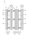
- FIG. 1 is a longitudinal sectional view schematically showing an example of a lithium secondary battery according to an embodiment of the present disclosure
- FIG. FIG. 2 is a cross-sectional view schematically showing part of the lithium secondary battery shown in FIG. 1
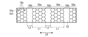
- FIG. 4 is a top view showing an example of a pattern of spacers
- FIG. 10 is a top view showing another example of a pattern of spacers
- FIG. 10 is a top view showing another example of a pattern of spacers
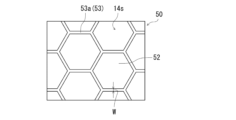
- FIG. 6 is a partially enlarged view of FIG. 5;
- lithium secondary battery A lithium secondary battery according to an embodiment of the present disclosure will be described below.
- the lithium secondary battery may be hereinafter referred to as “lithium secondary battery (L)”.
- Two lithium secondary batteries will be described below as “lithium secondary batteries (L)”. They are hereinafter sometimes referred to as “lithium secondary battery (L1)” and “lithium secondary battery (L2)”.
- a lithium secondary battery (L1) includes a positive electrode, a negative electrode, a separator disposed between the positive electrode and the negative electrode, and a non-aqueous electrolyte having lithium ion conductivity.
- the negative electrode is an electrode in which lithium metal is deposited during charging and lithium metal is dissolved during discharging.
- a separator includes a substrate and a spacer. The spacer is arranged closer to the positive electrode side than the substrate. The spacer includes linear projections arranged in a mesh pattern. The mesh pattern includes defects that connect adjacent areas within the mesh.
- the lithium secondary battery (L2) includes a positive electrode, a negative electrode, a separator disposed between the positive electrode and the negative electrode, and a non-aqueous electrolyte having lithium ion conductivity.
- the negative electrode is an electrode in which lithium metal is deposited during charging and lithium metal is dissolved during discharging.
- a separator includes a substrate and a spacer. The spacer is arranged closer to the positive electrode side than the substrate. The spacer includes linear projections arranged in a mesh pattern. The separator includes a first region having a mesh pattern and a second region having no mesh pattern.
- the lithium secondary battery (L1) and the lithium secondary battery (L2) differ only in the spacer arrangement pattern (spacer planar shape). Therefore, the following description is applicable to both the lithium secondary battery (L1) and the lithium secondary battery (L2) unless otherwise noted or contradicted. Also, the matters described for the lithium secondary battery (L) can be applied to both the lithium secondary battery (L1) and the lithium secondary battery (L2).
- the form in which the element B is formed on the element A includes the form in which the element B is directly formed on the element A, and the form in which the element B is formed directly on the element A Forms in which B is formed are included.
- a lithium secondary battery (L) is also called a lithium metal secondary battery.
- the negative electrode of this type of battery lithium metal deposits during charging and dissolves during discharging.
- the negative electrode has at least a negative electrode current collector, and lithium metal is deposited on the negative electrode current collector.
- a lithium secondary battery for example, 70% or more of the rated capacity is expressed by deposition and dissolution of lithium metal. Electron movement at the negative electrode during charge and discharge is primarily due to deposition and dissolution of lithium metal at the negative electrode. Specifically, 70-100% (eg, 80-100% or 90-100%) of the electron transfer (or current in another aspect) at the negative electrode during charging and discharging is due to the deposition and dissolution of lithium metal. That is, the negative electrode according to the present disclosure differs from a negative electrode in which electron movement in the negative electrode during charge and discharge is mainly due to lithium ion absorption and release by the negative electrode active material (such as graphite).
- the negative electrode active material such as graphite
- the positive electrode, the negative electrode, and the separator may be collectively referred to as an "electrode group".
- the positive electrode, the negative electrode, and the separator may be wound such that the separator is positioned between the positive electrode and the negative electrode.
- a strip-shaped positive electrode, a strip-shaped negative electrode, and a strip-shaped separator are used.
- the positive electrode, the negative electrode and the separator may be laminated.
- a flat positive electrode, a flat negative electrode, and a flat separator may be stacked. That is, the electrode group may be a wound electrode group or a laminated electrode group.
- a spacer secures a space between the positive electrode and the negative electrode.
- the spacer is arranged on the positive electrode side of the separator and forms a space on the surface of the positive electrode.
- lithium metal is deposited on the surface of the negative electrode. Due to the deposited lithium metal, the portion of the separator where there is no spacer moves to the positive electrode side. Since the part where no spacer exists is a space, the separator (base material and heat-resistant layer) can move to the positive electrode side in that part. Therefore, expansion of the electrode group can be suppressed when charging and discharging are repeated.
- a base material or a heat-resistant layer exists on the surface of the negative electrode. Therefore, lithium metal can be prevented from being deposited in a coarse state. Therefore, expansion of the negative electrode can be suppressed.
- the separator spacer includes a mesh pattern.
- the mesh pattern includes a defect.
- a non-aqueous electrolyte can move through the defect. If there are no defects, the fluidity of the non-aqueous electrolyte is lowered, and the characteristics of the battery may be lowered.
- the non-aqueous electrolyte can move through the defective portion, such deterioration in characteristics can be suppressed. As a result, a high discharge capacity retention rate can be achieved.
- the separator of the lithium secondary battery (L2) includes a second region where no mesh pattern is formed.
- the non-aqueous electrolyte In the second region, the non-aqueous electrolyte is freely movable. Without the second region, the fluidity of the non-aqueous electrolyte may be reduced and the battery characteristics may be deteriorated.
- the non-aqueous electrolyte since the non-aqueous electrolyte can move through the second region, such deterioration in characteristics can be suppressed. As a result, a high discharge capacity retention rate can be achieved.
- the spacer when a spacer is arranged on the positive electrode, the spacer covers the surface of the positive electrode, so that the transfer of lithium ions by the positive electrode active material is partially inhibited. As a result, the cell capacity may decrease.
- the spacer in the lithium secondary battery (L), the spacer is formed on the separator, so the above problem can be avoided. That is, according to the lithium secondary battery (L), it is possible to both suppress the expansion of the negative electrode and maintain a high cell capacity, and furthermore, it is possible to suppress the temperature rise of the battery in the event of an abnormality.
- lithium metal freely precipitates and dissolves on the surface of the negative electrode during charging and discharging.
- a short circuit due to dendrites may easily occur, or an increase in side reactions due to an increase in the surface area of the negative electrode may occur.
- An increase in side reactions leads to a decrease in capacity retention rate.
- the lithium secondary battery (L) since the spacer is arranged on the positive electrode side, no space is formed by the spacer on the surface of the negative electrode. Therefore, according to the lithium secondary battery (L), it is possible to achieve high reliability and high capacity retention rate.
- the lithium secondary battery (L2) preferably satisfies at least one of the following conditions (J1) to (J3), and may satisfy two or all of the conditions.
- the lithium secondary battery (L2) may satisfy the following conditions (J2) and (J3).
- J1 A first region having a mesh pattern and a second region having no mesh pattern are alternately arranged along the longitudinal direction LD of the separator.
- J2 The length L1 of the first region in the longitudinal direction LD of the separator is longer than the length L2 of the second region in the longitudinal direction LD.
- the ratio L1/L2 between the length L1 and the length L2 is greater than 1, may be 2 or more or 3 or more, and may be 10 or less or 5 or less.
- the length L2 of the second region in the longitudinal direction LD of the separator is 1 mm or more and 15 mm or less.
- the length L2 may be 1 mm or more, 3 mm or more, or 5 mm or more, and may be 15 mm or less or 10 mm or less.
- the average height Hs of the spacers is greater than the average thickness Tb of the base material.
- the ratio Hs/Tb between the average height Hs and the average thickness Tb may be greater than 1, greater than or equal to 1.5, greater than or equal to 2, or greater than or equal to 3.
- the ratio Hs/Tb may be 10 or less, 8 or less, 5 or less, or 4 or less.
- the average height Hs can be measured by the following method. First, a cross section of the separator in the thickness direction of the separator is photographed with an electron microscope to obtain an image of the cross section. Next, in the image, 20 arbitrary locations of the spacer are selected, and the height of the spacer at that location is measured. Next, the heights measured at 20 points are arithmetically averaged, and the obtained average value is defined as the average height Hs.
- the average thickness Tb and the average thickness Tt of the heat-resistant layer which will be described later, can also be measured in the same procedure.
- the average thickness Tb of the base material may be 5 ⁇ m or more or 10 ⁇ m or more, and may be 30 ⁇ m or less or 20 ⁇ m or less.
- the average thickness Tt of the heat-resistant layer which will be described later, may be 1 ⁇ m or more or 2 ⁇ m or more, or may be 5 ⁇ m or less or 3 ⁇ m or less.
- the average height Hs of the spacers may be 10 ⁇ m or more, or 20 ⁇ m or more, and may be 100 ⁇ m or less, 50 ⁇ m or less, 40 ⁇ m or less, or 30 ⁇ m or less. These heights and thicknesses may vary depending on the configurations of the positive and negative electrodes, and may take values outside the ranges exemplified here. In order to keep the distance between the electrode plates formed by the spacers as constant as possible, the spacers are usually formed so that their heights are as constant as possible.
- the missing portion no spacer is formed in the missing portion.
- the missing portion may be formed so that the non-aqueous electrolyte in the space (region) within the mesh formed by the spacer can move to the adjacent space when the electrode group is formed. Therefore, the missing portion may be formed by reducing the height of a portion of the spacer.
- the height of a part of the spacer may be 50% or less (for example, 30% or less, 20% or less, or 10% or less) of the spacer average height Hs to form the missing portion.
- the average height Hd of the missing portion may be 0% or more, 3% or more, 5% or more, 10% or more, or 20% or more of the average height Hs.
- the non-aqueous electrolyte can move between adjacent meshes while maintaining the mesh-like connected pattern.
- the effect of suppressing the shrinkage of the base material when the temperature of the electrode group rises can be particularly enhanced.
- the amount of slurry (or coating liquid) applied for forming the spacer may be changed depending on the location.
- the spacer preferably includes a non-porous structure impermeable to lithium ions.
- Such spacers can be realized by forming the spacers under conditions that do not make them porous.
- the phrase "lithium ions do not permeate" means that an amount that affects the characteristics and shape of the battery does not permeate. Including when moving within.
- the area S1 of the spacer may be 30% or less of the area S0 of the separator. According to this range, it is possible to secure a sufficient space for deposition of lithium metal.
- the area S1 and the area S0 are respective areas of the separator when viewed from the spacer side.
- the ratio S1/S0 between the area S1 and the area S0 may be 0.20 or less (20% or less) or 0.10 or less, and may be 0.03 or more (3% or more) or 0.05 or more. good too. By setting this ratio to 0.05 or more (5% or more), the effect of suppressing excessive temperature rise of the electrode group can be enhanced.
- the separator may include at least one heat-resistant layer.
- the heat-resistant layer may be formed on the main surface on the positive electrode side of the two main surfaces of the substrate, may be formed on the main surface on the negative electrode side, or may be formed on each of the two main surfaces. may be formed on the
- the spacer may be formed on the heat-resistant layer, or may be formed on the substrate without the heat-resistant layer interposed therebetween.
- the separator may have a configuration of base material/heat-resistant layer/spacer, heat-resistant layer/base material/spacer, or heat-resistant layer/base material/heat-resistant layer/spacer. In these configurations, the spacer is placed on the positive electrode side. That is, the separator is arranged such that the spacer faces the positive electrode.
- the heat-resistant layer is formed on one of the two main surfaces of the substrate on the positive electrode side, and the spacer is formed on the heat-resistant layer.
- the spacer is formed on the heat-resistant layer.
- the average height Hs of the spacers is preferably larger than the total Tw of the average thickness Tb of the substrate and the average thickness Tt of the heat-resistant layer.
- the ratio Hs/Tw between the average height Hs and the total Tw may be greater than 1, greater than or equal to 1.5, greater than or equal to 2, or greater than or equal to 3.
- the ratio Hs/Tw may be 10 or less, 8 or less, 5 or less, or 4 or less.
- the heat-resistant layer can suppress contraction of the base material when the temperature of the electrode group rises excessively.
- the base material shrinks, short-circuiting between the positive electrode and the negative electrode is more likely to occur, and the temperature of the electrode group is more likely to rise.
- the shrinkage of the base material can be suppressed, so that the further temperature rise of the electrode group can be suppressed.
- the spacer not only secures a space between the electrode plates, but by combining it with a heat-resistant layer, it is possible to dramatically improve the effect of suppressing an excessive temperature rise in the electrode group.
- a porous sheet having ion permeability and insulation is used as the base material.
- porous sheets include porous membranes, woven fabrics, non-woven fabrics, and the like.
- the material of the separator is not particularly limited, but may be a polymer material.
- polymeric materials include polyolefin resins, polyamide resins, cellulose, and the like.
- polyolefin resins include polyethylene, polypropylene and copolymers of ethylene and propylene.
- the base material may contain additives as needed. An inorganic filler etc. are mentioned as an additive.
- a sheet used as a separator for a lithium secondary battery may be used as the base material.
- the spacer may contain resin (for example, insulating resin) or may contain resin and particles.
- the spacer may be composed only of resin, or may be composed of resin and particles.
- the ratio of the resin in the spacer may be 10% by volume or more, 30% by volume or more, or 50% by volume or more, and may be 100% by volume or less, or 80% by volume or less.
- the particle content in the spacer may be lower than the particle content in the heat-resistant layer.
- resin materials include fluorine-containing resins such as polyvinylidene fluoride (PVdF) and polytetrafluoroethylene, fluorine-containing rubbers such as vinylidene fluoride-tetrafluoroethylene copolymers and ethylene-tetrafluoroethylene copolymers, and styrene.
- PVdF polyvinylidene fluoride
- fluorine-containing rubbers such as vinylidene fluoride-tetrafluoroethylene copolymers and ethylene-tetrafluoroethylene copolymers
- styrene styrene
- Non-porous spacers having a certain height or more made of these resin materials are layers impermeable to lithium ions.
- the average height of the spacer may be 3 times or more, 5 times or more, or 10 times or more, and 100 times or less, 30 times or less, or 20 times the average thickness of the heat-resistant layer. It may be twice or less.
- the particles may be inorganic particles or organic particles.
- inorganic particles such as insulating metal oxides, metal hydroxides, metal nitrides, metal carbides and metal sulfides can be mentioned.
- Preferred metal oxides include aluminum oxide (alumina and boehmite), magnesium oxide, titanium oxide (titania), zirconium oxide, silicon oxide (silica), and the like.
- Aluminum hydroxide etc. can be mentioned as a metal hydroxide.
- metal nitrides include silicon nitride, aluminum nitride, boron nitride, and titanium nitride.
- metal carbides include silicon carbide and boron carbide. Barium sulfate etc.
- a metal sulfide can be mentioned as a metal sulfide.
- Minerals such as aluminosilicate, layered silicate, barium titanate, and strontium titanate may also be used. Among them, it is preferable to use alumina, silica, titania, or the like.
- the average particle size of the particles is not particularly limited, but may be 0.1 ⁇ m or more or 0.5 ⁇ m or more, or may be 10 ⁇ m or less, 5 ⁇ m or less, or 2 ⁇ m or less.
- the average particle size can be measured by the following method. First, a cross section of the spacer in the thickness direction of the separator is photographed with an electron microscope to obtain an image of the cross section. Next, image processing such as binarization is performed on the image to identify the particle portion. Next, the diameter of a circle having the same area as the cross-sectional area of each particle (equivalent circle diameter) is determined, and the arithmetic mean of the determined equivalent circle diameters can be used as the average particle diameter. Arithmetic averages can be determined, for example, from 100 or more particles. The average particle size of other particles contained in the electrode plate and separator can also be determined in a similar manner.
- the content of particles in the spacer is preferably 50% by volume or less. This makes it easier to ensure sufficient strength of the spacer.
- the area S1 of the spacer may be 30% or less of the area S0 of the separator. According to this range, it is possible to secure a sufficient space for deposition of lithium metal.
- the area S1 and the area S0 are respective areas of the separator when viewed from the spacer side.
- the ratio S1/S0 between the area S1 and the area S0 may be 0.20 or less (20% or less) or 0.10 or less, and may be 0.03 or more (3% or more) or 0.05 or more. good too. By setting this ratio to 0.05 or more (5% or more), the effect of suppressing excessive temperature rise of the electrode group can be enhanced.
- the spacers may include dot-shaped protrusions in addition to linear protrusions.
- a linear convex part is a ridge-shaped convex part from one viewpoint.
- the spacer preferably includes a linear projection, and may be composed only of a linear projection.
- the width of the linear projection may be 100 ⁇ m or more or 200 ⁇ m or more, or may be 2000 ⁇ m or less or 1000 ⁇ m or less.
- the mesh pattern may be an aggregate of polygons.
- An example of a mesh pattern includes a shape in which polygons are combined so as to share sides. Polygons include triangles, quadrilaterals, hexagons, and the like. Different types of polygons may be combined.
- the mesh pattern may be honeycomb-like.
- the missing portions may be formed at the positions of the sides of the polygons forming the mesh pattern. Alternatively, the missing portions may be formed at the positions of the vertices of the polygons forming the mesh pattern. Alternatively, they may be formed at the positions of the sides and vertices of the polygon.
- the total length of the missing portions along the linear projection may be 1% or more, 5% or more, or 10% or more of the total length of the linear projection, 80% or less, It may be 65% or less, or 50% or less. By increasing this ratio, the liquid circulation of the non-aqueous electrolyte can be improved.
- this ratio may be in the range of 10 to 50%.
- the total length of the missing portion along the linear convex portion is 1% of the total length of the linear convex portion. 5% or more, or 10% or more, or 50% or less, 30% or less, or 20% or less.
- the lithium secondary battery (L2) may include a first region in which a mesh pattern is formed and a second region in which no mesh pattern is formed.
- a preferred example of the spacer satisfies the following conditions (J4) and/or (J5). When the following conditions are satisfied, it is possible to achieve a good balance between securing a space for depositing lithium metal and suppressing an excessive temperature rise of the electrode assembly.
- J4 A ratio S1/S0 between the area S1 and the area S0 is 0.30 or less. The ratio S1/S0 may be in the range described above.
- J5 The width of the linear projections forming the spacer is 2000 ⁇ m or less. The width of the protrusion may be within the range described above.
- the first resin forming the spacer preferably has higher heat resistance than the second resin forming the base material.
- high heat resistance means that the decomposition temperature or melting point of the first resin is higher than the decomposition temperature or melting point of the second resin.
- each of the first resin and the second resin may contain a plurality of types of resins.
- the heat-resistant layer may contain a polymer (hereinafter sometimes referred to as "polymer (PL)”) and inorganic particles.
- the inorganic particles may include first particles of phosphate containing lithium, and may further include second particles other than phosphate.
- the heat-resistant layer is a layer permeable to lithium ions.
- the phosphate constituting the first particles is selected from the group consisting of lithium phosphate (Li 3 PO 4 ), dilithium hydrogen phosphate (Li 2 HPO 4 ), and lithium dihydrogen phosphate (LiH 2 PO 4 ). At least one may be selected. Among these, lithium phosphate is preferable because it is highly effective in suppressing heat generation of the battery in the event of an abnormality.
- the average particle diameter of the first particles is in the range of 0.1 ⁇ m to 1.0 ⁇ m (for example, the range of 0.1 ⁇ m to 0.5 ⁇ m, the range of 0.1 ⁇ m to 0.2 ⁇ m, or the range of 0.1 ⁇ m to 0.19 ⁇ m ).
- the average particle size of the first particles may be 0.1 ⁇ m or greater, or 0.15 ⁇ m or greater.
- the average particle size of the first particles may be 1.0 ⁇ m or less, 0.5 ⁇ m or less, 0.3 ⁇ m or less, or 0.2 ⁇ m or less.
- By setting the average particle size to 0.1 ⁇ m or more sufficient pores necessary for permeation of the electrolytic solution can be secured. Setting the average particle diameter to 1.0 ⁇ m or less is preferable from the viewpoint of forming a high-density layer of the first particles.
- the polymer (PL) a polymer having higher heat resistance than the main component of the base material of the separator can be used.
- the polymer (PL) preferably contains at least one selected from the group consisting of aromatic polyamides, aromatic polyimides, and aromatic polyamideimides. These are known as polymers (otherwise macromolecules or resins) with high heat resistance. From the viewpoint of heat resistance, aramids, that is, meta-aramids (meta-based wholly aromatic polyamides) and para-aramids (para-based wholly aromatic polyamides) are preferred.
- One preferred example polymer (PL) is a meta-aramid.
- Known aromatic polyamides, aromatic polyimides, and aromatic polyamideimides may be used for the polymer (PL).
- aromatic polyamides examples include polymers formed by condensation polymerization of monomers having aromatic skeletons and containing amide bonds in repeating units.
- aromatic polyamides examples include meta aromatic polyamides (eg meta wholly aromatic polyamides) and para aromatic polyamides (eg para wholly aromatic polyamides).
- Wholly aromatic polyamides are also called aramids.
- a preferred example of the second particles is a particle composed of an insulating inorganic compound that does not melt or decompose when the battery abnormally heats up.
- the second particles may be inorganic particles that are commonly used as inorganic fillers. Examples of materials for the second particles include oxides, oxide hydrates, hydroxides, nitrides, carbides, sulfides, etc., which may contain metallic elements.
- the average particle size of the second particles may be 0.2 ⁇ m or more and 2 ⁇ m or less.
- oxides and oxide hydrates include aluminum oxide, boehmite, magnesium oxide, titanium oxide, zirconium oxide, silicon oxide, yttrium oxide, and zinc oxide.
- nitrides include silicon nitride, aluminum nitride, boron nitride, titanium nitride, and the like.
- carbides include silicon carbide, boron carbide, and the like.
- sulfides include barium sulfate and the like.
- hydroxides include aluminum hydroxide and the like.
- the material of the second particles may be porous aluminosilicate such as zeolite, layered silicate such as talc, barium titanate (BaTiO 3 ), strontium titanate (SrTiO 3 ), or the like. At least one selected from the group consisting of aluminum oxide, boehmite, talc, titanium oxide, and magnesium oxide may be used as the material of the second particles from the viewpoint of insulation and heat resistance.
- the average particle size of the second particles may be within the range exemplified for the average particle size of the first particles.
- the inorganic particles may include the first particles and second particles other than phosphate.
- the heat-resistant layer may include a first layer containing the first particles and a second layer containing the second particles. According to this configuration, it is possible to particularly enhance the effect of suppressing an excessive temperature rise of the electrode group.
- the heat-resistant layer may be composed of only the first layer or only the second layer.
- the first layer and the second layer may be laminated on the main surface on the positive electrode side, may be laminated on the main surface on the negative electrode side, or may be laminated on different main surfaces.
- the separator can be: substrate/first layer/second layer/spacer, substrate/second layer/first layer/spacer, first layer/second layer/substrate/spacer, Alternatively, it may have a laminated structure of second layer/first layer/base material/spacer. Alternatively, the first layer and the second layer may be disposed on different major surfaces of the substrate.
- the separator may have a laminated structure of first layer/substrate/second layer/spacer or second layer/substrate/first layer/spacer. The separator is arranged such that the spacer faces the positive electrode. That is, the spacer is arranged closer to the positive electrode side than the base material and the heat-resistant layer.
- the first layer may contain the first particles as a main component.
- the content of the first particles in the first layer may be in the range of 50% by mass to 99% by mass, may be in the range of 85% by mass to 99% by mass, or may be in the range of 90% by mass to It may be in the range of 98% by weight.
- the content may be 50% by mass or more, 70% by mass or more, 85% by mass or more, or 90% by mass or more.
- the content may be 99% by mass or less, 98% by mass or less, or 95% by mass or less.
- the first particles have a sufficient surface area and it is easy to deactivate lithium at high temperatures.
- the first layer may contain solid components other than the first particles.
- the first layer may contain a binder, an inorganic material other than the first particles (for example, inorganic particles), a polymer (PL), and the like.
- the content of the binder in the first layer may be in the range of 1% by mass to 15% by mass, and in the range of 2% by mass to 10% by mass. There may be.
- the content of the binder in the first layer may be 1% by mass or more or 2% by mass or more.
- the binder content in the first layer may be 15% by mass or less or 10% by mass or less.
- the binder contained in the first layer is not particularly limited, and may be polyolefin (polyethylene, polypropylene, copolymer of ethylene and ⁇ -olefin, etc.), fluorine-containing resin (polyvinylidene fluoride, polytetrafluoroethylene, polyfluoride vinyl, etc.), fluorine-containing rubber (vinylidene fluoride-hexafluoropropylene-tetrafluoroethylene copolymer, ethylene-tetrafluoroethylene copolymer, etc.), styrene-butadiene copolymer and its hydride, acrylonitrile-butadiene copolymer Included are coalescences and their hydrides, acrylonitrile-butadiene-styrene copolymers and their hydrides, N-vinylacetamide.
- the second layer includes second particles other than the first particles (phosphate particles).
- the second layer may or may not contain the first particles.
- the second layer preferably contains a polymer (PL).
- the polymer (PL) content in the second layer may be in the range of 50% to 100% by weight (eg 80% to 100% by weight or 90% to 100% by weight).
- the second layer may consist of polymer (PL) only.
- the second layer may contain second particles as a main component.
- the content of the second particles in the second layer may be in the range of 50% to 99% by weight (eg, in the range of 85% to 99% by weight).
- the second layer may also contain a binder.
- the binding material the binding materials exemplified in the description of the first layer can be used.
- the content of the second particles in the second layer may be 50% by mass or more, 70% by mass or more, 85% by mass or more, or 90% by mass or more.
- the content may be 99% by mass or less, 98% by mass or less, or 95% by mass or less.
- the thickness of the first and second layers may independently be in the range of 0.2 ⁇ m to 10 ⁇ m (eg, in the range of 1 ⁇ m to 8 ⁇ m, or in the range of 2 ⁇ m to 4 ⁇ m, or in the range of 4 ⁇ m to 10 ⁇ m).
- the thickness of the first layer may range from 0.2 ⁇ m to 10 ⁇ m and the thickness of the second layer may range from 0.2 ⁇ m to 10 ⁇ m.
- the thickness of the first layer may be 0.2 ⁇ m or more, 0.3 ⁇ m or more, or 0.5 ⁇ m or more, preferably 1 ⁇ m or more, more preferably 2 ⁇ m or more, 3 ⁇ m or more is more preferable, and 4 ⁇ m or more is even more preferable.
- the thickness of the first layer may be 10 ⁇ m or less, 8 ⁇ m or less, or 7 ⁇ m or less, 5 ⁇ m or less.
- the thickness of the second layer may be 0.2 ⁇ m or more, 0.3 ⁇ m or more, or 0.5 ⁇ m or more, preferably 1 ⁇ m or more, more preferably 2 ⁇ m or more, 3 ⁇ m or more is more preferable, and 4 ⁇ m or more is even more preferable.
- the thickness of the second layer may be 10 ⁇ m or less, 8 ⁇ m or less, or 7 ⁇ m or less, 5 ⁇ m or less.
- the first layer and the second layer has a thickness of 0.2 ⁇ m or more, it is advantageous in suppressing an increase in battery temperature in the event of an abnormality.
- the first layer and the second layer has a thickness of 10 ⁇ m or less, it is advantageous in terms of the electrical characteristics of the battery.
- the heat-resistant layer contains the first particles, it is possible to particularly suppress the temperature rise of the battery in the event of an abnormality.
- the mechanism is not clear at present.
- One possibility is that the first particles react with the lithium metal of the negative electrode when the battery temperature rises abnormally, reducing the reactivity of the surface of the lithium metal.
- a preferable example of the separator may satisfy the following condition (K1) and further satisfy the following conditions (K2) and/or (K3). Excessive temperature rise of the electrode group can be particularly suppressed by satisfying the following conditions.
- the spacer contains at least one resin selected from the group consisting of polyvinylidene fluoride, acrylonitrile-acrylate copolymer, and polyimide.
- the heat-resistant layer contains at least one resin selected from the group consisting of wholly aromatic polyamide, polyvinylidene fluoride, and N-vinylacetamide. In that case, the heat-resistant layer preferably contains phosphate particles.
- the base material contains polyolefin (polyethylene, polypropylene, etc.) as a main component (content: 50% by mass or more).
- the method for producing the separator is not particularly limited, and the separator may be produced by the following method. First, a base material is prepared. A commercially available substrate may be used. Next, a heat-resistant layer is formed on the substrate.
- the method of forming the heat-resistant layer is not particularly limited, and may be formed by the following method. First, a slurry (or coating liquid) is formed by mixing components of the heat-resistant layer and a liquid component (dispersion medium). Next, the slurry (or coating liquid) is applied to a substrate to form a coating film, and then the coating film is dried. Thus, a heat-resistant layer can be formed.
- a slurry or coating liquid
- the slurry (or coating liquid) is applied to a substrate to form a coating film, and then the coating film is dried.
- a heat-resistant layer can be formed.
- each layer may be formed by the method described above.
- each step in forming the heat-resistant layer there is no particular limitation on each step in forming the heat-resistant layer, and known methods can be applied.
- the slurry (or coating liquid) may be applied by a known method such as a method using a bar coater.
- drying may be performed by a known method such as drying by heating or natural drying.
- the spacer is formed on the heat-resistant layer or base material.
- a method for forming the spacer is not particularly limited, and the spacer may be formed by the following method. First, a slurry or coating solution is prepared by mixing spacer components and liquid components. Next, the slurry or the coating liquid is applied to the portions where the spacers are to be formed, and then dried. Spacers can be formed in this manner. Examples of liquid components include N-methyl-2-pyrrolidone and the like. Application of the slurry or coating liquid may be performed using a dispenser or the like, or may be performed using a known printing method such as gravure printing, inkjet printing, or screen printing. Moreover, drying may be performed by a known method such as drying by heating or natural drying. A separator is obtained as described above. The missing portion can be formed, for example, by partially not applying the slurry (or the coating liquid), or by applying less slurry (or the coating liquid) than the other portions.
- each component of the lithium secondary battery will be specifically described below. Note that the constituent elements described below are merely examples, and the constituent elements of the lithium secondary battery of the present embodiment are not limited to the following constituent elements. You may use a well-known component for components other than the part characteristic of this embodiment. Since the separator has been described above, redundant description will be omitted.
- the negative electrode includes a negative electrode current collector.
- lithium metal is deposited on the negative electrode current collector by charging. More specifically, lithium ions contained in the non-aqueous electrolyte receive electrons on the negative electrode current collector during charging to become lithium metal, which is deposited on the negative electrode current collector. Lithium metal deposited on the negative electrode current collector dissolves as lithium ions in the non-aqueous electrolyte due to discharge.
- the lithium ions contained in the non-aqueous electrolyte may be derived from the lithium salt added to the non-aqueous electrolyte, or may be supplied from the positive electrode active material during charging. There may be.
- a conductive sheet can be used for the negative electrode current collector.
- a strip-shaped conductive sheet is used.
- Examples of conductive sheets include conductive films, metal foils, and the like.
- the surface of the conductive sheet may be smooth. This facilitates uniform deposition of lithium metal derived from the positive electrode on the conductive sheet during charging. Smooth means that the maximum height roughness Rz of the conductive sheet is 20 ⁇ m or less. The maximum height roughness Rz of the conductive sheet may be 10 ⁇ m or less. The maximum height roughness Rz is measured according to JIS (Japanese Industrial Standard) B 0601:2013.
- the material of the negative electrode current collector may be any conductive material other than lithium metal and lithium alloy.
- the conductive material may be a metallic material such as a metal, an alloy, or the like.
- the conductive material is preferably a material that does not react with lithium. More specifically, materials that form neither alloys nor intermetallic compounds with lithium are preferred.
- Such conductive materials include, for example, copper (Cu), nickel (Ni), iron (Fe), alloys containing these metal elements, or graphite in which the basal plane is preferentially exposed.
- alloys include copper alloys and stainless steel (SUS). Copper and/or copper alloys are preferred because of their high electrical conductivity.
- the thickness of the negative electrode current collector is not particularly limited, and may be in the range of 5 to 300 ⁇ m.
- a negative electrode mixture layer may be formed on the surface of the negative electrode current collector.
- the negative electrode mixture layer is formed, for example, by applying a paste containing a negative electrode active material such as graphite to at least part of the surface of the negative electrode current collector.
- the thickness of the negative electrode mixture layer is set sufficiently thin so that lithium metal can be deposited on the negative electrode.
- the negative electrode may include a negative electrode current collector and a sheet-like lithium metal or lithium alloy placed on the negative electrode current collector. That is, the negative electrode current collector may be provided in advance with a base layer containing lithium metal (lithium metal or lithium alloy layer). Lithium alloys may contain elements other than lithium, such as aluminum, magnesium, indium, and zinc. By providing the underlying layer in advance and depositing lithium metal thereon during charging, dendrite-like deposition can be more effectively suppressed.
- the thickness of the underlayer is not particularly limited, but may be in the range of 5 ⁇ m to 25 ⁇ m, for example.
- the positive electrode includes, for example, a positive electrode current collector and a positive electrode mixture layer supported by the positive electrode current collector.
- the positive electrode mixture layer includes, for example, a positive electrode active material, a conductive material, and a binder.
- the positive electrode mixture layer may be formed only on one side of the positive electrode current collector, or may be formed on both sides.
- the positive electrode is obtained, for example, by applying a positive electrode mixture slurry containing a positive electrode active material, a conductive material, and a binder on both sides of a positive electrode current collector, drying the coating film, and then rolling.
- a positive electrode active material is a material that absorbs and releases lithium ions.
- positive electrode active materials include lithium-containing transition metal oxides, transition metal fluorides, polyanions, fluorinated polyanions, and transition metal sulfides. Among them, lithium-containing transition metal oxides are preferable in terms of low production cost and high average discharge voltage.
- the transition metal elements contained in the lithium-containing transition metal oxide include Sc, Ti, V, Cr, Mn, Fe, Co, Ni, Cu, Y, Zr, W, and the like.
- the lithium-containing transition metal oxide may contain one or more transition metal elements.
- the transition metal elements may be Co, Ni and/or Mn.
- the lithium-containing transition metal oxide may contain one or more main group elements as needed. Typical elements include Mg, Al, Ca, Zn, Ga, Ge, Sn, Sb, Pb, and Bi. A typical element may be Al or the like.
- lithium-containing transition metal oxides composite oxides containing Co, Ni and/or Mn as transition metal elements and optionally containing Al, and having a layered structure and a rock salt type crystal structure are highly This is preferable in terms of obtaining capacity.
- the molar ratio of the total amount mLi of lithium possessed by the positive electrode and the negative electrode to the amount mM of the metal M other than lithium possessed by the positive electrode: mLi/mM is set to, for example, 1.1 or less. be done.
- the conductive material is, for example, a carbon material.
- carbon materials include carbon black, acetylene black, ketjen black, carbon nanotubes, and graphite.
- binders include fluorine resins, polyacrylonitrile, polyimide resins, acrylic resins, polyolefin resins, and rubber-like polymers.
- fluororesins include polytetrafluoroethylene and polyvinylidene fluoride.
- the positive electrode current collector may be a conductive sheet.
- a foil, a film, or the like is used as the conductive sheet.
- a carbon material may be applied to the surface of the positive electrode current collector.
- Examples of materials for the positive electrode current collector include metal materials containing Al, Ti, Fe, and the like.
- the metal material may be Al, Al alloy, Ti, Ti alloy, Fe alloy, or the like.
- the Fe alloy may be stainless steel (SUS).
- the thickness of the positive electrode current collector is not particularly limited, and may be in the range of 5 to 300 ⁇ m.
- a non-aqueous electrolyte having lithium ion conductivity includes, for example, a non-aqueous solvent and lithium ions and anions dissolved in the non-aqueous solvent.
- the non-aqueous electrolyte may be liquid or gel.
- a liquid non-aqueous electrolyte is prepared by dissolving a lithium salt in a non-aqueous solvent. Lithium ions and anions are generated by dissolving the lithium salt in the non-aqueous solvent.
- a gel-like non-aqueous electrolyte contains a lithium salt and a matrix polymer, or a lithium salt, a non-aqueous solvent and a matrix polymer.
- the matrix polymer for example, a polymer material that gels by absorbing a non-aqueous solvent is used. Examples of polymer materials include fluorine resins, acrylic resins, polyether resins, and the like.
- lithium salt or anion known ones used for non-aqueous electrolytes of lithium secondary batteries can be used. Specific examples include BF 4 ⁇ , ClO 4 ⁇ , PF 6 ⁇ , CF 3 SO 3 ⁇ , CF 3 CO 2 ⁇ , anions of imides, and anions of oxalate complexes.
- the anion of the oxalate complex may contain boron and/or phosphorus.
- the anion of the oxalate complex includes bisoxalate borate anion, BF 2 (C 2 O 4 ) ⁇ , PF 4 (C 2 O 4 ) ⁇ , PF 2 (C 2 O 4 ) 2 ⁇ and the like.
- the non-aqueous electrolyte may contain these anions singly or in combination of two or more.
- the non-aqueous electrolyte preferably contains at least an anion of an oxalate complex. Due to the interaction between the anion of the oxalate complex and lithium, the lithium metal is easily precipitated uniformly in the form of fine particles. Therefore, it becomes easier to suppress local deposition of lithium metal. You may combine the anion of an oxalate complex with another anion. Other anions may be PF 6 - and/or imide class anions.
- the non-aqueous electrolyte may contain LiBF 2 (C 2 O 4 ) (lithium difluorooxalatoborate) as a solute (lithium salt).
- non-aqueous solvents examples include esters, ethers, nitriles, amides, and halogen-substituted products thereof.
- the non-aqueous electrolyte may contain one of these non-aqueous solvents, or two or more of them. Fluoride etc. are mentioned as a halogen substitution body.
- esters include carbonic acid esters and carboxylic acid esters.
- Cyclic carbonates include ethylene carbonate, propylene carbonate, fluoroethylene carbonate (FEC), and the like.
- Chain carbonic acid esters include dimethyl carbonate (DMC), ethylmethyl carbonate (EMC), diethyl carbonate and the like.
- Cyclic carboxylic acid esters include ⁇ -butyrolactone, ⁇ -valerolactone and the like. Examples of chain carboxylic acid esters include ethyl acetate, methyl propionate, and methyl fluoropropionate.
- Ethers include cyclic ethers and chain ethers.
- Cyclic ethers include 1,3-dioxolane, 4-methyl-1,3-dioxolane, tetrahydrofuran, 2-methyltetrahydrofuran and the like.
- Chain ethers include 1,2-dimethoxyethane, diethyl ether, ethyl vinyl ether, methylphenyl ether, benzyl ethyl ether, diphenyl ether, dibenzyl ether, 1,2-diethoxyethane, diethylene glycol dimethyl ether and the like.
- the concentration of the lithium salt in the non-aqueous electrolyte is, for example, 0.5 mol/L or more and 3.5 mol/L or less.
- the anion concentration in the non-aqueous electrolyte may be 0.5 mol/L or more and 3.5 mol/L or less.
- the concentration of the anion of the oxalate complex in the non-aqueous electrolyte may be 0.05 mol/L or more and 1 mol/L or less.
- the non-aqueous electrolyte may contain additives.
- the additive may form a film on the negative electrode. Formation of the film derived from the additive on the negative electrode facilitates suppression of the formation of dendrites. Examples of such additives include vinylene carbonate, FEC, vinyl ethyl carbonate (VEC), and the like.
- lithium secondary battery of the present embodiment An example of the lithium secondary battery of the present embodiment will be specifically described below with reference to the drawings.
- the components described above can be applied to the components of the example lithium secondary battery described below.
- the components of the example described below can be modified based on the above description.
- the matters described below may be applied to the above embodiments.
- components that are not essential for the lithium secondary battery according to the present disclosure may be omitted. It should be noted that in the following figures, the scale of the constituent elements has been changed to facilitate understanding.
- FIG. 1 is a longitudinal sectional view schematically showing an example of a lithium secondary battery according to Embodiment 1.
- FIG. A cylindrical lithium secondary battery 10 shown in FIG. 1 includes a cylindrical battery case, and a wound electrode group 14 and a non-aqueous electrolyte (not shown) housed in the battery case.
- the battery case includes a case body 15 which is a bottomed cylindrical metal container, and a sealing member 16 which seals the opening of the case body 15 .
- a gasket 27 is arranged between the case main body 15 and the sealing member 16 . Gasket 27 ensures hermeticity of the battery case.
- Insulating plates 17 and 18 are arranged at both ends of the electrode group 14 in the winding axis direction in the case main body 15 .
- the case body 15 has, for example, a stepped portion 21 formed by partially pressing the side wall of the case body 15 from the outside.
- the stepped portion 21 may be annularly formed on the side wall of the case body 15 along the circumferential direction of the case body 15 .
- the sealing member 16 is supported by the surface of the stepped portion 21 on the opening side.
- the sealing body 16 includes a filter 22, a lower valve body 23, an insulating member 24, an upper valve body 25, and a cap 26. In the sealing member 16, these members are laminated in this order.
- the sealing member 16 is attached to the opening of the case body 15 so that the cap 26 is positioned outside the case body 15 and the filter 22 is positioned inside the case body 15 .
- Each of the members constituting the sealing member 16 is, for example, disk-shaped or ring-shaped.
- the lower valve body 23 and the upper valve body 25 are connected to each other at their central portions, and an insulating member 24 is interposed between their peripheral edge portions.
- the filter 22 and the lower valve body 23 are connected to each other at their central portions.
- the upper valve body 25 and the cap 26 are connected to each other at their central portions. That is, each member except the insulating member 24 is electrically connected to each other.
- a ventilation hole (not shown) is formed in the lower valve body 23 . Therefore, when the internal pressure of the battery case rises due to abnormal heat generation or the like, the upper valve body 25 swells toward the cap 26 side and separates from the lower valve body 23 . Thereby, the electrical connection between the lower valve body 23 and the upper valve body 25 is cut off. When the internal pressure further increases, the upper valve body 25 is broken, and gas is discharged from an opening (not shown) formed in the cap 26 .
- FIG. 2 is an enlarged view of part of the electrode group 14.
- FIG. FIG. 2 includes a portion near the positive electrode surrounded by region II in FIG. 1 and a portion near the negative electrode surrounded by region III in FIG.
- the electrode group 14 has a positive electrode 11 , a negative electrode 12 and a separator 50 .
- the positive electrode 11, the negative electrode 12, and the separator 50 are all belt-shaped.
- the strip-shaped positive electrode 11 and negative electrode 12 are spirally wound with a separator 50 interposed therebetween such that the width direction of the strip-shaped positive electrode 11 and negative electrode 12 is parallel to the winding axis.
- the positive electrode 11 and the negative electrode 12 are alternately laminated in the radial direction of the electrode group 14 with the separator 50 interposed therebetween. . That is, the longitudinal direction of each electrode is the winding direction, and the width direction of each electrode is the axial direction.
- the positive electrode 11 includes a positive electrode current collector 11a and a positive electrode mixture layer 11b.
- the positive current collector 11a is electrically connected via a positive lead 19 to a cap 26 functioning as a positive terminal.
- a negative electrode negative electrode current collector
- the negative electrode 12 is electrically connected via a negative lead 20 to a case body 15 functioning as a negative terminal.
- the separator 50 includes a base material 51, a heat-resistant layer 52, and spacers 53.
- the heat-resistant layer 52 is formed on the main surface 51 a of the two main surfaces 51 a and 51 b of the base material 51 on the positive electrode 11 side.
- the heat-resistant layer 52 is preferably formed so as to cover at least a region sandwiched between the positive electrode 11 and the negative electrode 12 on at least one main surface of the base material 51 .
- the heat-resistant layer 52 may be formed so as to entirely cover one side of the substrate 51 , or may be formed so as to entirely cover both surfaces of the substrate 51 .
- a spacer 53 is formed on the heat-resistant layer 52 .
- spacer 53 is in contact with negative electrode 12 .
- a space 14 s is formed by the spacer 53 on the surface of the positive electrode 11 (between the heat-resistant layer 52 and the positive electrode 11 ).
- the substrate 51 exists on the surface of the negative electrode 12 .
- FIG. 2 shows the height h of the spacer 53.
- the heat-resistant layer 52 is an optional component.
- lithium metal is deposited on the negative electrode 12 during charging.
- the lithium metal deposited on the negative electrode 12 pushes up the portion of the separator 50 (the base material 51 and the heat-resistant layer 52) where the spacer 53 does not exist, toward the positive electrode 11 side.
- lithium metal is deposited in the space 14s.
- the deposited lithium metal dissolves in the non-aqueous electrolyte during discharge. Since the lithium metal deposited on the surface of the negative electrode 12 is accommodated in the space 14s, the volume change of the electrode group 14 due to the deposition of the lithium metal is reduced, and the cycle characteristics are improved.
- the spacer 53 When the spacer 53 is permeable to lithium ions, the lithium ions pass through the spacer 53 during charging. Lithium ions that have passed through the spacer 53 are deposited between the base material 51 and the negative electrode 12 at the portion where the spacer 53 is formed. As a result, the thickness of the electrode group 14 in the stacking direction is increased. Therefore, the spacers 53 are preferably impermeable to lithium ions.
- the stacking direction means the radial direction of the wound electrode group.
- FIG. 3 shows the longitudinal direction LD of the separator 50 . Note that other drawings may also show the longitudinal direction LD of the separator 50 .
- the spacer 53 is composed of a linear projection 53a.
- the linear protrusions 53a are arranged in a mesh pattern, and more specifically, are uniformly formed in a honeycomb pattern.
- a honeycomb pattern is a pattern in which a plurality of hexagons are arranged so as to share sides with each other.
- a region in which the linear convex portion 53a is not formed constitutes a space 14s.
- the honeycomb pattern (mesh pattern) shown in FIG. 3 has a missing portion 53b.
- FIG. 3 shows an example in which a missing portion 53b is formed on a side forming a polygon (a hexagon in FIG. 3).
- Embodiment 1 shows an example in which the spacer 53 is not formed at all in the cutout portion 53b. However, as described above, at least a portion of the cutout portion 53b may be a portion of the spacer 53 with a reduced height.
- the missing portion 53b may be formed in a portion other than the side.
- FIG. 4 shows an example of the planar shape of the spacer 53 in which the missing portion 53b is formed at the vertex of the polygon.
- the spacer 53 in FIG. 4 has a honeycomb pattern, and the honeycomb pattern has a missing portion 53b.
- the cutout portion 53b is formed at the vertex portion of the hexagon.
- FIG. 3 shows an example in which the missing portions 53b are formed on all sides
- FIG. 4 shows an example in which the missing portions 53b are formed on all vertices.
- a part of the mesh area (space 14s) may not be connected to the adjacent mesh area (space 14s) via the missing portion 53b.
- the ratio (number ratio) of areas connected to adjacent mesh areas (spaces 14s) via missing portions 53b is 50% or more. Preferably, it is 70% or more, 80% or more, or 90% or more and 100% or less. In a preferred example, all mesh areas (spaces 14s) are connected to adjacent mesh areas (spaces 14s) via cutouts 53b.
- Embodiment 2 describes an example of a lithium secondary battery (L2). Since Embodiment 2 differs from the lithium secondary battery of Embodiment 1 only in the arrangement pattern of the spacers, redundant description will be omitted.
- FIG. 5 shows part of the arrangement pattern of the spacers 53 in the separator 50 of the lithium secondary battery of Embodiment 2.
- An enlarged view of a portion of the pattern of FIG. 5 is shown in FIG.
- FIG. 6 shows the width W of the linear protrusion 53a.
- the separator 50 in FIG. 5 includes linear projections 53a arranged in a mesh pattern.
- the separator 50 includes a first region 50a having a mesh pattern and a second region 50b having no mesh pattern.
- the first regions 50 a and the second regions 50 b are alternately arranged along the longitudinal direction LD of the separator 50 .
- the length L1 of the first region 50a in the longitudinal direction LD is longer than the length L2 of the second region 50b in the longitudinal direction LD.
- Embodiments 1 and 2 a cylindrical lithium secondary battery with a wound electrode group has been described.
- the lithium secondary battery of this embodiment is not limited to the form of Embodiment 1, and can be applied to other forms.
- the shape of the lithium secondary battery can be appropriately selected from various shapes such as cylindrical, coin-shaped, rectangular, sheet-shaped, flat-shaped, etc., according to its use.
- the form of the electrode group is also not particularly limited, and may be a laminated type.
- NMP N-methyl-2-pyrrolidone
- the resulting positive electrode mixture slurry was applied to both sides of a strip-shaped Al foil (positive electrode current collector), and then dried to form a coating film of the positive electrode mixture.
- the coating film was rolled using a roller.
- the obtained laminate of the positive electrode current collector and the positive electrode mixture was cut into a predetermined electrode size to prepare a positive electrode having positive electrode mixture layers on both sides of the positive electrode current collector.
- a band-shaped porous polyethylene film (average thickness: 10 ⁇ m) was prepared as a base material.
- a heat-resistant layer (having an average thickness of 2 ⁇ m) was formed on one side of the substrate. The heat-resistant layer was formed by forming the second layer and the first layer in this order on the substrate.
- the second layer was formed as follows. First, N-methyl-2-pyrrolidone (NMP) and calcium chloride were mixed at a mass ratio of 94.2:5.8. The mixture was heated to about 80° C. to completely dissolve the calcium chloride. Then, this solution was returned to room temperature, and 2200 g of the solution was sampled, and then 0.6 mol of paraphenylenediamine (PPD) was added and dissolved completely. While this solution was kept at about 20° C., 0.6 mol of terephthaloyl dichloride (TPC) was added little by little. The obtained solution was aged at about 20° C. for 1 hour to obtain a polymerization solution.
- NMP N-methyl-2-pyrrolidone
- PPD paraphenylenediamine
- TPC terephthaloyl dichloride
- the coating liquid was applied onto the substrate by a slot die method to form a coating film.
- the base material on which the coating film was formed was left in an atmosphere of 25° C. and 70% relative humidity for 1 hour to precipitate the aromatic polyamide.
- NMP and calcium chloride in the coating film were removed by washing with water.
- a second layer was then formed by drying the coating at 60° C. for 5 minutes.
- the first layer was formed as follows. First, particles of lithium phosphate (Li 3 PO 4 ) and poly-N-vinylacetamide (PNVA) were mixed at a mass ratio of 100:8 to obtain a mixture. Lithium phosphate particles having a volume-based median diameter of 0.19 ⁇ m were used. Water (ion-exchanged water) was added to the resulting mixture and stirred to prepare a slurry (coating liquid) having a solid content concentration of 12% by mass. The slurry was then coated onto the second layer by microgravure coating to form a coating. Next, the coating film was dried in a drying oven attached to the coating machine. Thus, a first layer was formed. Thus, a heat-resistant layer was formed.
- Li 3 PO 4 lithium phosphate
- PNVA poly-N-vinylacetamide
- a coating liquid containing polyvinylidene fluoride and alumina particles (inorganic filler) was discharged onto the heat-resistant layer in the pattern shown in FIG. After that, the coating liquid was vacuum-dried. Thus, the honeycomb-shaped non-porous spacer shown in FIG. 3 was formed.
- the mesh shape of the spacer was a regular hexagon including the missing part.
- the height of the linear projections was set to 30 ⁇ m (average height: 30 ⁇ m). Of the sides forming the mesh of the regular hexagons, the distance between the two opposing sides was about 2.25 mm.
- the width of the linear protrusion was 0.25 mm.
- the planar shape of the missing portion was 0.25 mm ⁇ 0.25 mm.
- the spacer area S1 was 16.7% of the separator area S0.
- the obtained electrode group was housed in a bag-shaped exterior body formed of a laminate sheet having an Al layer, and after the non-aqueous electrolyte was injected into the exterior body containing the electrode group, the exterior body was sealed. Thus, a lithium secondary battery A1 was produced.
- Battery A2 was produced in the same manner and under the same conditions as the method for producing battery A1, except that the spacer pattern was changed.
- spacers having the arrangement pattern shown in FIG. 4 were formed.
- the mesh shape of the spacer was a regular hexagon including the missing portion.
- the size of the regular hexagon and the height and width of the linear protrusions were the same as those of the separator of battery A1.
- the size of the missing portion was approximately the same as the size of the missing portion of the spacer of Battery A1. Therefore, the ratio between the area S1 of the spacer and the area S0 of the separator is also approximately the same as that of the separator of the battery A1.
- Battery A3 was produced in the same manner and under the same conditions as the method for producing battery A1, except that the spacer pattern was changed.
- spacers having the arrangement pattern shown in FIG. 5 were formed.
- the mesh shape of the spacer was a regular hexagon.
- the size of the regular hexagon and the height and width of the linear protrusions were the same as those of the separator of battery A1.
- the length L1 of the first region in the longitudinal direction LD was set to 90 mm, and the length L2 of the second region in the longitudinal direction LD was set to 10 mm.
- the spacer area S1 was 18% of the separator area S0.
- Battery C1 A battery C1 was produced in the same manner and under the same conditions as the method for producing the battery A1, except that the spacer pattern was changed.
- a spacer composed of a plurality of linear protrusions arranged in stripes was used. Each linear projection was arranged along the width direction of the separator (the direction perpendicular to the longitudinal direction LD). The interval between adjacent linear projections was 2.25 mm. The height and width of the linear projections were the same as those of the separator of battery A1.
- the spacer area S1 was 20% of the separator area S0.
- Battery C2 A battery C2 was produced in the same manner and under the same conditions as the method for producing the battery A1, except that the pattern of the spacer was changed. Battery C2 used the same spacer as battery A1, except that no defect was formed. That is, in Battery C2, the spacers were arranged in a honeycomb pattern. The spacer area S1 was 21% of the separator area S0.
- battery C3 In battery C3, the spacer was formed on the positive electrode instead of the separator.
- the spacer was formed by the same method as the method for forming the spacer in Battery A1.
- the spacers had the same arrangement pattern and the same size as the spacers of battery C1.
- Battery C4 In Battery C4, the spacer was formed on the positive electrode instead of the separator.
- the spacer was formed by the same method as the method for forming the spacer in Battery A1.
- the spacers had the same arrangement pattern and the same size as the spacers of battery C2.
- a plurality of batteries produced as described above were evaluated by the following methods.
- (Charging and discharging test) A charge/discharge test was performed on each of the obtained batteries. In the charge/discharge test, the battery was charged under the following conditions in a constant temperature bath at 25° C., then rested for 20 minutes, and then discharged under the following conditions.
- Constant current charging is performed at a current of 2.15 mA per unit area (square centimeter) of the electrode until the battery voltage reaches 4.1 V, and then at a voltage of 4.1 V, the current value per unit area of the electrode is 0.0. Constant voltage charging was performed until the battery reached 54 mA.
- the thickness was measured at five arbitrary points in the laminate, and the arithmetic mean of the five measured values was taken as the average thickness of the laminate.
- the average thickness X obtained by subtracting the thickness of the two substrates and the thickness of the two heat-resistant layers from this average thickness was obtained.
- the ratio (%) of the average thickness X at the second cycle to the average thickness X before charge/discharge was taken as the expansion coefficient of the electrode group. That is, the expansion rate (%) of the electrode group is the ratio of the average thickness X at the second cycle when the average thickness X before charge/discharge is 100%.
- discharge capacity retention rate The above charging and discharging were defined as one cycle, and charging and discharging were performed up to 50 cycles. The ratio (%) of the discharge capacity at the 50th cycle to the discharge capacity at the 1st cycle was determined as the discharge capacity retention rate. Also, the discharge capacity at the first cycle was defined as the initial discharge capacity.
- Table 1 shows some of the battery manufacturing conditions and evaluation results.
- the initial discharge capacity is expressed as a relative value when the initial discharge capacity of battery C3 is set to 100. It is preferable that the initial discharge capacity and the discharge capacity retention rate are high. It is preferable that the expansion coefficient of the electrode group is low.
- Batteries A1 to A3 are batteries according to the present disclosure, and batteries C1 to C4 are batteries of comparative examples. Batteries A1 to A3 had a high initial discharge capacity and a high discharge capacity retention rate, and a low expansion rate of the electrode group. On the other hand, in the battery C1 in which the spacers were formed in stripes, the expansion coefficient of the electrode group was high. It is considered that this is because when the electrode plate and the separator were wound, the position of the spacer was displaced and a sufficient space could not be formed between the electrode plates. The battery C2 using spacers without defective portions had a low discharge capacity retention rate. This is considered to be due to the influence of the spacer preventing the movement of the non-aqueous electrolyte. Batteries C3 and C4 in which spacers were formed on the positive electrodes had low initial discharge capacities. It is considered that this is because part of the positive electrode active material was not effectively utilized by the spacer.
- the present disclosure can be applied to lithium secondary batteries.
- the lithium secondary battery according to the present disclosure can be used for electronic devices such as mobile phones, smartphones, and tablet terminals, electric vehicles including hybrids and plug-in hybrids, household storage batteries combined with solar cells, and the like. While the present invention has been described in terms of presently preferred embodiments, such disclosure should not be construed as limiting. Various alterations and modifications will no doubt become apparent to those skilled in the art to which the invention pertains after reading the above disclosure. Therefore, the appended claims are to be interpreted as covering all variations and modifications without departing from the true spirit and scope of the invention.
Landscapes
- Chemical & Material Sciences (AREA)
- Chemical Kinetics & Catalysis (AREA)
- Electrochemistry (AREA)
- General Chemical & Material Sciences (AREA)
- Inorganic Chemistry (AREA)
- Engineering & Computer Science (AREA)
- Manufacturing & Machinery (AREA)
- Ceramic Engineering (AREA)
- Composite Materials (AREA)
- Materials Engineering (AREA)
- Physics & Mathematics (AREA)
- Condensed Matter Physics & Semiconductors (AREA)
- General Physics & Mathematics (AREA)
- Cell Separators (AREA)
- Secondary Cells (AREA)
Abstract
開示されるリチウム二次電池は、正極(11)と、負極(12)と、正極(11)と負極(12)との間に配置されたセパレータ(50)と、リチウムイオン伝導性を有する非水電解質とを含む。負極(12)は、充電時にリチウム金属が析出し、放電時にリチウム金属が溶解する電極である。セパレータ(50)は、基材(51)とスペーサ(53)とを含む。スペーサ(53)は、基材(51)よりも正極側に配置されている。スペーサ(53)は、網目状のパターンに配置された線状の凸部を含む。網目状のパターンは、隣接する網目内の領域を結ぶ欠損部を含む。
Description
本開示は、リチウム二次電池に関する。
非水電解質二次電池は、パソコンおよびスマートフォン等のICT用、車載用、ならびに蓄電用等の用途に用いられている。このような用途において、非水電解質二次電池には、さらなる高容量化が求められる。高容量の非水電解質二次電池としては、リチウムイオン電池が知られている。リチウムイオン電池の高容量化は、負極活物質として、例えば、黒鉛とケイ素化合物等の合金活物質とを併用することにより達成され得る。しかし、リチウムイオン電池の高容量化は限界に達しつつある。
リチウムイオン電池を超える高容量の非水電解質二次電池としては、リチウム二次電池(リチウム金属二次電池)が有望である。リチウム二次電池では、充電時に、負極にリチウム金属が析出し、このリチウム金属が放電時に非水電解質中に溶解する。リチウム二次電池について、従来から様々な提案がなされている。
特許文献1(国際公開第2020/066254号)は、「正極集電体と、正極活物質を含む正極合材層と、を含む正極と、前記正極に対向する負極集電体を含む負極と、
前記正極と前記負極との間に配置されるセパレータと、リチウムイオン伝導性を有する非水電解質と、を備え、前記正極活物質は、リチウムと、リチウム以外の金属Mと、を含む複合酸化物を含み、前記金属Mは、少なくとも遷移金属を含み、充電時に前記負極にリチウム金属が析出し、放電時に前記負極から前記リチウム金属が溶解し、前記正極集電体の第1方向D1における第1長さは、第1方向と交わる第2方向D2における第2長さよりも小さく、前記正極と前記負極との間に前記リチウム金属を収容する空間が形成されるように前記正極と前記セパレータとの間にスペーサが設けられており、前記スペーサを3箇所以上通過するように前記第1方向D1に沿って直線SLを描き得る、リチウム二次電池。」を開示している。
前記正極と前記負極との間に配置されるセパレータと、リチウムイオン伝導性を有する非水電解質と、を備え、前記正極活物質は、リチウムと、リチウム以外の金属Mと、を含む複合酸化物を含み、前記金属Mは、少なくとも遷移金属を含み、充電時に前記負極にリチウム金属が析出し、放電時に前記負極から前記リチウム金属が溶解し、前記正極集電体の第1方向D1における第1長さは、第1方向と交わる第2方向D2における第2長さよりも小さく、前記正極と前記負極との間に前記リチウム金属を収容する空間が形成されるように前記正極と前記セパレータとの間にスペーサが設けられており、前記スペーサを3箇所以上通過するように前記第1方向D1に沿って直線SLを描き得る、リチウム二次電池。」を開示している。
現在、リチウム二次電池の特性のさらなる向上が求められている。本開示の目的の1つは、特性(例えば放電容量維持率)がより高いリチウム二次電池を提供することである。
本開示の一側面は、リチウム二次電池に関する。当該リチウム二次電池は、正極と、負極と、前記正極と前記負極との間に配置されたセパレータと、リチウムイオン伝導性を有する非水電解質とを含み、前記負極は、充電時にリチウム金属が析出し、放電時に前記リチウム金属が溶解する電極であり、前記セパレータは、基材とスペーサとを含み、前記スペーサは、前記基材よりも前記正極側に配置されており、前記スペーサは、網目状のパターンに配置された線状の凸部を含み、前記網目状のパターンは、隣接する網目内の領域を結ぶ欠損部を含む。
本開示の他の一側面は、リチウム二次電池に関する。当該他のリチウム二次電池は、正極と、負極と、前記正極と前記負極との間に配置されたセパレータと、リチウムイオン伝導性を有する非水電解質とを含み、前記負極は、充電時にリチウム金属が析出し、放電時に前記リチウム金属が溶解する電極であり、前記セパレータは、基材とスペーサとを含み、前記スペーサは、前記基材よりも前記正極側に配置されており、前記スペーサは、網目状のパターンに配置された線状の凸部を含み、前記セパレータは、前記網目状のパターンが形成されている第1の領域と、前記網目状のパターンが形成されていない第2の領域とを含む。
本開示によれば、特性(例えば放電容量維持率)がより高いリチウム二次電池が得られる。
本発明の新規な特徴を添付の請求の範囲に記述するが、本発明は、構成および内容の両方に関し、本発明の他の目的および特徴と併せ、図面を照合した以下の詳細な説明によりさらによく理解されるであろう。
本発明の新規な特徴を添付の請求の範囲に記述するが、本発明は、構成および内容の両方に関し、本発明の他の目的および特徴と併せ、図面を照合した以下の詳細な説明によりさらによく理解されるであろう。
以下では、本開示に係る実施形態について例を挙げて説明するが、本開示に係る実施形態は以下で説明する例に限定されない。以下の説明では具体的な数値や材料を例示する場合があるが、本開示に係る発明を実施できる限り、他の数値や他の材料を適用してもよい。この明細書において、「数値A~数値B」という記載は、数値Aおよび数値Bを含み、「数値A以上で数値B以下」と読み替えることが可能である。以下の説明において、特定の物性や条件などの数値に関して下限と上限とを例示した場合、下限が上限以上とならない限り、例示した下限のいずれかと例示した上限のいずれかとを任意に組み合わせることができる。
(リチウム二次電池)
本開示に係る実施形態のリチウム二次電池について、以下に説明する。当該リチウム二次電池を以下では、「リチウム二次電池(L)」と称する場合がある。以下では、「リチウム二次電池(L)」として、2つのリチウム二次電池について説明する。それらを以下では、「リチウム二次電池(L1)」および「リチウム二次電池(L2)」と称する場合がある。
本開示に係る実施形態のリチウム二次電池について、以下に説明する。当該リチウム二次電池を以下では、「リチウム二次電池(L)」と称する場合がある。以下では、「リチウム二次電池(L)」として、2つのリチウム二次電池について説明する。それらを以下では、「リチウム二次電池(L1)」および「リチウム二次電池(L2)」と称する場合がある。
(リチウム二次電池(L1))
リチウム二次電池(L1)は、正極と、負極と、正極と負極との間に配置されたセパレータと、リチウムイオン伝導性を有する非水電解質とを含む。負極は、充電時にリチウム金属が析出し、放電時にリチウム金属が溶解する電極である。セパレータは、基材とスペーサとを含む。スペーサは、基材よりも正極側に配置されている。スペーサは、網目状のパターンに配置された線状の凸部を含む。網目状のパターンは、隣接する網目内の領域を結ぶ欠損部を含む。
リチウム二次電池(L1)は、正極と、負極と、正極と負極との間に配置されたセパレータと、リチウムイオン伝導性を有する非水電解質とを含む。負極は、充電時にリチウム金属が析出し、放電時にリチウム金属が溶解する電極である。セパレータは、基材とスペーサとを含む。スペーサは、基材よりも正極側に配置されている。スペーサは、網目状のパターンに配置された線状の凸部を含む。網目状のパターンは、隣接する網目内の領域を結ぶ欠損部を含む。
(リチウム二次電池(L2))
リチウム二次電池(L2)は、正極と、負極と、正極と負極との間に配置されたセパレータと、リチウムイオン伝導性を有する非水電解質とを含む。負極は、充電時にリチウム金属が析出し、放電時にリチウム金属が溶解する電極である。セパレータは、基材とスペーサとを含む。スペーサは、基材よりも正極側に配置されている。スペーサは、網目状のパターンに配置された線状の凸部を含む。セパレータは、網目状のパターンが形成されている第1の領域と、網目状のパターンが形成されていない第2の領域とを含む。
リチウム二次電池(L2)は、正極と、負極と、正極と負極との間に配置されたセパレータと、リチウムイオン伝導性を有する非水電解質とを含む。負極は、充電時にリチウム金属が析出し、放電時にリチウム金属が溶解する電極である。セパレータは、基材とスペーサとを含む。スペーサは、基材よりも正極側に配置されている。スペーサは、網目状のパターンに配置された線状の凸部を含む。セパレータは、網目状のパターンが形成されている第1の領域と、網目状のパターンが形成されていない第2の領域とを含む。
リチウム二次電池(L1)とリチウム二次電池(L2)とは、スペーサの配置パターン(スペーサの平面形状)のみが異なる。そのため、以下の説明は、注記または矛盾がない限り、リチウム二次電池(L1)およびリチウム二次電池(L2)の両方に適用できる。また、リチウム二次電池(L)について説明した事項は、リチウム二次電池(L1)およびリチウム二次電池(L2)の両方に適用できる。
この明細書において、要素Aの上に要素Bが形成されている形態には、要素Aの上に要素Bが直接形成されている形態、および、要素Aの上に他の要素を介して要素Bが形成されている形態が含まれる。
リチウム二次電池(L)は、リチウム金属二次電池とも称される。この種の電池の負極では、充電時にリチウム金属が析出し、放電時にリチウム金属が溶解する。具体的には、負極は、少なくとも負極集電体を有し、リチウム金属は負極集電体上に析出する。
リチウム二次電池(L)では、定格容量の例えば70%以上がリチウム金属の析出と溶解により発現する。充電時および放電時の負極における電子の移動は、主に負極におけるリチウム金属の析出および溶解による。具体的には、充電時および放電時の負極における電子の移動(別の観点では電流)の70~100%(例えば80~100%や90~100%)がリチウム金属の析出および溶解による。すなわち、本開示に係る負極は、充電時および放電時の負極における電子の移動が主に負極活物質(黒鉛など)によるリチウムイオンの吸蔵および放出による負極とは異なる。
以下では、正極と負極とセパレータとをまとめて、「電極群」と称する場合がある。正極と負極とセパレータとは、正極と負極との間にセパレータが配置されるように巻回されてもよい。巻回型の電極群を形成する場合、帯状の正極、帯状の負極、および帯状のセパレータが用いられる。あるいは、正極と負極とセパレータとは、積層されてもよい。例えば、平らな正極と平らな負極と平らなセパレータとが、積層されてもよい。すなわち、電極群は、巻回型の電極群であってもよいし、積層型の電極群であってもよい。
リチウム二次電池(L)では、正極と負極との間の空間がスペーサによって確保される。スペーサは、セパレータのうち正極側に配置されており、正極の表面に空間を形成する。充電時には、負極の表面にリチウム金属が析出する。析出したリチウム金属によって、セパレータのうちスペーサがない部分が正極側に移動する。スペーサが存在しない部分は空間となっているため、その部分はセパレータ(基材および耐熱層)が正極側に移動可能である。そのため、充放電を繰り返したときに、電極群が膨張することを抑制できる。また、リチウム二次電池(L)では、負極の表面に基材または耐熱層が存在する。そのため、リチウム金属が粗な状態で析出することを抑制できる。そのため、負極の膨張を抑制できる。
さらに、リチウム二次電池(L)では、セパレータのスペーサが網目状のパターンを含む。これによって、電極群を積層または巻回したときに、スペーサの位置がずれて極板が望ましくない曲がり方をすることを抑制できる。そのため、リチウム二次電池(L)によれば、スペーサによってリチウム金属が析出する空間を適切に形成できる。
リチウム二次電池(L1)のセパレータでは、網目状のパターンが欠損部を含む。欠損部を介して、非水電解質が移動可能である。欠損部がない場合、非水電解質の流動性が低下し、電池の特性が低下する場合がある。リチウム二次電池(L1)では、欠損部を介して非水電解質が移動可能であるため、そのような特性の低下を抑制できる。その結果、高い放電容量維持率を達成できる。
リチウム二次電池(L2)のセパレータは、網目状のパターンが形成されていない第2の領域を含む。第2の領域では、非水電解質が自由に移動可能である。第2の領域がない場合、非水電解質の流動性が低下し、電池の特性が低下する場合がある。リチウム二次電池(L2)では、第2の領域を介して非水電解質が移動可能であるため、そのような特性の低下を抑制できる。その結果、高い放電容量維持率を達成できる。
また、正極上にスペーサを配置した場合、スペーサが正極表面を被覆するため、正極活物質によるリチウムイオンの授受が部分的に阻害される。その結果、セル容量の低下を招くことがある。これに対し、リチウム二次電池(L)ではセパレータ上にスペーサを形成しているため、上記のような問題を回避できる。すなわち、リチウム二次電池(L)によれば、負極の膨張の抑制と高いセル容量の維持とを両立することが可能であり、さらに、異常時における電池の温度上昇を抑制できる。
スペーサによる空間が負極表面に配置されると、充放電時に、リチウム金属が負極の表面に自由に析出・溶解する。その結果、デンドライトによる短絡が生じやすくなったり、負極の表面積の増加による副反応の増加が生じやすくなったりする場合がある。副反応の増加は、容量維持率の低下を招く。一方、リチウム二次電池(L)では、スペーサを正極側に配置しているため、負極の表面には、スペーサによる空間が配置されない。そのため、リチウム二次電池(L)によれば、高い信頼性および高い容量維持率を達成することが可能である。
リチウム二次電池(L2)は、以下の条件(J1)~(J3)の少なくとも1つを満たすことが好ましく、2つ、またはすべての条件を満たしてもよい。例えば、リチウム二次電池(L2)は、以下の条件(J2)および(J3)を満たしてもよい。
(J1)網目状のパターンが形成されている第1の領域と、網目状のパターンが形成されていない第2の領域とが、セパレータの長手方向LDに沿って交互に配置されている。
(J2)セパレータの長手方向LDにおける第1の領域の長さL1は、長手方向LDにおける第2の領域の長さL2よりも長い。長さL1と長さL2との比L1/L2は、1より大きく、2以上または3以上であってもよく、10以下または5以下であってもよい。
(J3)セパレータの長手方向LDにおける第2の領域の長さL2は、1mm以上で15mm以下である。なお、長さL2は、1mm以上、3mm以上、または5mm以上であってもよく、15mm以下または10mm以下であってもよい。
スペーサの平均高さHsは、基材の平均厚さTbよりも大きい。平均高さHsと平均厚さTbとの比Hs/Tbは、1より大きく、1.5以上、2以上、または3以上であってもよい。比Hs/Tbは、10以下、8以下、5以下、または4以下であってもよい。この比を1.5以上とすることによって、電極群の膨張率を特に低減できる。また、スペーサを高くすることによってスペーサの強度が高まるため、過熱時における基材の収縮を抑制する効果が高まる。その結果、電極群の過剰な温度上昇を特に抑制できる。
平均高さHsは、以下の方法で測定できる。まず、セパレータの厚さ方向におけるセパレータの断面を電子顕微鏡で撮影し、断面の画像を得る。次に、当該画像において、スペーサのうちの任意の20箇所を選択し、その箇所のスペーサの高さを測定する。次に、測定された20箇所の高さを算術平均し、得られた平均値を平均高さHsとする。平均厚さTb、および後述する耐熱層の平均厚さTtも、同様の手順で測定できる。
基材の平均厚さTbは、5μm以上または10μm以上であってもよく、30μm以下、または20μm以下であってもよい。後述する耐熱層の平均厚さTtは、1μm以上または2μm以上であってもよく、5μm以下または3μm以下であってもよい。スペーサの平均高さHsは、10μm以上または20μm以上であってもよく、100μm以下、50μm以下、40μm以下、または30μm以下であってもよい。これらの高さおよび厚さは、正極および負極の構成によっても変わり、ここに例示した範囲以外の数値を取り得る。なお、スペーサによって形成される極板間の間隔ができるだけ一定になるように、スペーサは、通常、高さができるだけ一定になるように形成される。
欠損部の一例では、欠損部の部分にはスペーサが全く形成されない。しかし、欠損部は、電極群を構成したときに、スペーサで構成された網目内の空間(領域)にある非水電解質が、隣接する空間に移動可能なように形成されればよい。そのため、欠損部は、スペーサの一部の高さを低くすることによって形成してもよい。例えば、スペーサの一部の高さを、スペーサの平均高さHsの50%以下(例えば30%以下や20%以下や10%以下)とすることによって欠損部を形成してもよい。当該欠損部の平均高さHdは、平均高さHsの0%以上、3%以上、5%以上、10%以上、または20%以上としてもよい。スペーサの一部を残して欠損部とすることによって、網目状につながっているパターンを維持したまま、隣接する網目間で非水電解質の移動が可能になる。網目状につながっているパターンを維持することによって、電極群の温度が上昇したときに基材の収縮を抑制する効果を特に高めることができる。スペーサの一部の高さを低くする場合、例えば、スペーサを形成するためのスラリー(または塗液)の塗布量を、場所によって変えればよい。
スペーサは、リチウムイオンが透過しない非多孔質構造を含むことが好ましい。このようなスペーサは、スペーサを形成する際に、多孔質とならない条件で形成することによって実現できる。なお、この明細書において、「リチウムイオンが透過しない」とは、電池の特性や形状に影響を与える量が透過しないことを意味し、実質的に透過していないとみなせる量のリチウムイオンがスペーサ内を移動する場合を含む。
スペーサの面積S1は、セパレータの面積S0の30%以下であってもよい。この範囲によれば、リチウム金属が析出する空間を充分に確保できる。なお、面積S1および面積S0はそれぞれ、セパレータをスペーサの側からみたときのそれぞれの面積である。面積S1と面積S0との比S1/S0は、0.20以下(20%以下)または0.10以下であってもよく、0.03以上(3%以上)または0.05以上であってもよい。この比を0.05以上(5%以上)とすることによって、電極群の過剰な温度上昇を抑制する効果を高めることができる。
セパレータは少なくとも1つの耐熱層を含んでもよい。耐熱層は、基材の2つの主面のうちの正極側の主面上に形成されていてもよいし、負極側の主面上に形成されていてもよいし、2つの主面のそれぞれの上に形成されていてもよい。スペーサは、耐熱層上に形成されていてもよいし、基材上に耐熱層を介さずに形成されていてもよい。例えば、セパレータは、基材/耐熱層/スペーサ、耐熱層/基材/スペーサ、または耐熱層/基材/耐熱層/スペーサという構成を有してもよい。これらの構成において、スペーサは、正極側に配置される。すなわち、セパレータは、スペーサが正極と対向するように配置される。一例では、耐熱層は、基材の2つの主面のうちの正極側の主面上に形成されており、スペーサは、耐熱層上に形成されている。耐熱層上にスペーサを形成することによって、基材の熱収縮を抑制する効果が特に高くなる。
スペーサの平均高さHsは、基材の平均厚さTbと耐熱層の平均厚さTtとの合計Twよりも大きいことが好ましい。平均高さHsと合計Twとの比Hs/Twは、1より大きく、1.5以上、2以上、または3以上であってもよい。比Hs/Twは、10以下、8以下、5以下、または4以下であってもよい。
基材の表面に形成された耐熱層をセパレータが含む場合、耐熱層によって、電極群の温度が過剰に上昇したときに、基材の収縮を抑制できる。基材が収縮すると、それによって正極と負極とが短絡しやすくなるため、電極群の温度がさらに上昇しやすくなる。セパレータが耐熱層を含むことによって、基材の収縮を抑制できるため、電極群のさらなる温度上昇を抑制できる。
さらに、スペーサは、極板間にスペースを確保するだけでなく、耐熱層と組み合わせることによって、電極群の過剰な温度上昇を抑制する効果が飛躍的に高めることが可能である。
耐熱層とスペーサとを組み合わせることによって上記の効果が得られる理由は現在のところ明確ではない。しかし、基材の熱収縮を抑制する耐熱層の効果が、スペーサによって顕著に増大されている可能性がある。
耐熱層を正極側に配置することによって、基材が酸化反応によって劣化することを抑制できる。一方、耐熱層を負極側に配置することによって、基材が還元反応によって劣化することを抑制できる。
(基材)
基材には、イオン透過性および絶縁性を有する多孔性シートが用いられる。多孔性シートの例には、多孔質膜、織布、不織布などが含まれる。セパレータの材質は特に限定されないが、高分子材料であってもよい。高分子材料の例には、ポリオレフィン樹脂、ポリアミド樹脂、セルロースなどが含まれる。ポリオレフィン樹脂の例には、ポリエチレン、ポリプロピレンおよびエチレンとプロピレンとの共重合体などが含まれる。基材は、必要に応じて、添加剤を含んでもよい。添加剤としては、無機フィラー等が挙げられる。基材には、リチウム二次電池のセパレータとして用いられているシートを用いてもよい。
基材には、イオン透過性および絶縁性を有する多孔性シートが用いられる。多孔性シートの例には、多孔質膜、織布、不織布などが含まれる。セパレータの材質は特に限定されないが、高分子材料であってもよい。高分子材料の例には、ポリオレフィン樹脂、ポリアミド樹脂、セルロースなどが含まれる。ポリオレフィン樹脂の例には、ポリエチレン、ポリプロピレンおよびエチレンとプロピレンとの共重合体などが含まれる。基材は、必要に応じて、添加剤を含んでもよい。添加剤としては、無機フィラー等が挙げられる。基材には、リチウム二次電池のセパレータとして用いられているシートを用いてもよい。
(スペーサ)
スペーサは、樹脂(例えば絶縁性樹脂)を含んでもよく、樹脂と粒子とを含んでもよい。スペーサは、樹脂のみによって構成されてもよいし、樹脂と粒子とによって構成されてもよい。スペーサにおける樹脂の割合は、10体積%以上、30体積%以上、または50体積%以上であってもよく、100体積%以下、または80体積%以下であってもよい。スペーサにおける粒子の含有率は、耐熱層における粒子の含有率よりも低くてもよい。
スペーサは、樹脂(例えば絶縁性樹脂)を含んでもよく、樹脂と粒子とを含んでもよい。スペーサは、樹脂のみによって構成されてもよいし、樹脂と粒子とによって構成されてもよい。スペーサにおける樹脂の割合は、10体積%以上、30体積%以上、または50体積%以上であってもよく、100体積%以下、または80体積%以下であってもよい。スペーサにおける粒子の含有率は、耐熱層における粒子の含有率よりも低くてもよい。
樹脂材料としては、例えば、ポリフッ化ビニリデン(PVdF)、ポリテトラフルオロエチレン等の含フッ素樹脂、フッ化ビニリデン-テトラフルオロエチレン共重合体、エチレン-テトラフルオロエチレン共重合体等の含フッ素ゴム、スチレン-ブタジエン共重合体またはその水素化物、アクリロニトリル-ブタジエン共重合体またはその水素化物、メタクリル酸エステル-アクリル酸エステル共重合体、スチレン-アクリル酸エステル共重合体、アクリロニトリル-アクリル酸エステル共重合体、エチレンプロピレンラバー、ポリビニルアルコール、ポリ酢酸ビニル等のゴム類、エチルセルロース、メチルセルロース、ヒドロキシエチルセルロース、カルボキシメチルセルロース等のセルロース誘導体、アクリル酸-メタリル酸共重合体等のアクリル樹脂、ポリフェニレンエーテル、ポリスルホン、ポリエーテルスルホン、ポリフェニレンスルフィド、ポリエーテルイミド、ポリイミド、全芳香族ポリアミド(アラミド)等のポリアミド、ポリアミドイミド、ポリアクリロニトリル、ポリビニルアルコール、ポリエーテル、ポリアクリル酸、ポリメタリル酸、ポリエステル、ポリオレフィン、シリコーン樹脂、ウレタン樹脂、メラミン樹脂、ユリア樹脂、エポキシ樹脂が挙げられる。
上記の樹脂材料の中でも、リチウムイオンが透過しない材料としては、ポリイミド、ポリフッ化ビニリデン、アクリロニトリル-アクリル酸エステル共重合体などが好ましく、ポリイミドを用いてもよい。これらの樹脂材料で形成された一定の高さ以上の非多孔質のスペーサは、リチウムイオンが透過しない層である。セパレータが耐熱層を含む場合、スペーサの平均高さは、耐熱層の平均厚さの3倍以上、5倍以上、または10倍以上であってもよく、100倍以下、30倍以下、または20倍以下であってもよい。
粒子は、無機粒子でもよく、有機粒子でもよい。中でも、絶縁性の金属酸化物、金属水酸化物、金属窒化物、金属炭化物、金属硫化物等の無機粒子を挙げることができる。金属酸化物としては、酸化アルミニウム(アルミナやベーマイト)、酸化マグネシウム、酸化チタン(チタニア)、酸化ジルコニウム、酸化ケイ素(シリカ)等を好ましい材料として挙げることができる。金属水酸化物としては水酸化アルミニウム等を挙げることができる。金属窒化物としては、窒化ケイ素、窒化アルミニウム、窒化硼素、窒化チタン等を挙げることができる。金属炭化物としては、炭化ケイ素、炭化ホウ素等を挙げることができる。金属硫化物としては、硫酸バリウム等を挙げることができる。また、アルミノケイ酸塩、層状ケイ酸塩、チタン酸バリウム、チタン酸ストロンチウム等の鉱物を用いてもよい。中でも、アルミナ、シリカ、チタニアなどを用いることが好ましい。
粒子の平均粒径は、特に限定されないが、0.1μm以上または0.5μm以上であってもよく、10μm以下、5μm以下、または2μm以下であってもよい。平均粒径は、以下の方法で測定できる。まず、セパレータの厚さ方向におけるスペーサの断面を電子顕微鏡で撮影し、断面の画像を得る。次に、当該画像に対して二値化などの画像処理を行って粒子の部分を特定する。次に、各粒子の断面の面積と同じ面積を有する円の直径(円相当径)を求め、求められた円相当径の算術平均を、平均粒径とすることができる。算術平均は、例えば100個以上の粒子から求めることができる。なお、極板およびセパレータに含まれる他の粒子の平均粒径も、同様の方法で求めることができる。
スペーサが樹脂材料と粒子とを含む場合、スペーサにおける粒子の含有率は50体積%以下であることが好ましい。これにより、スペーサの充分な強度を確保しやすくなる。
スペーサの面積S1は、セパレータの面積S0の30%以下であってもよい。この範囲によれば、リチウム金属が析出する空間を充分に確保できる。なお、面積S1および面積S0はそれぞれ、セパレータをスペーサの側からみたときのそれぞれの面積である。面積S1と面積S0との比S1/S0は、0.20以下(20%以下)または0.10以下であってもよく、0.03以上(3%以上)または0.05以上であってもよい。この比を0.05以上(5%以上)とすることによって、電極群の過剰な温度上昇を抑制する効果を高めることができる。
スペーサは、線状の凸部に加えて、ドット状の凸部を含んでもよい。線状の凸部は、1つの観点では、リッジ状の凸部である。電極群の過剰な温度上昇を抑制する効果を高める点で、スペーサは、線状の凸部を含むことが好ましく、線状の凸部のみで構成されてもよい。
線状の凸部の幅は、100μm以上または200μm以上であってもよく、2000μm以下、または1000μm以下であってもよい。
網目状のパターンは、多角形の集合体であってもよい。網目状のパターンの一例には、辺を共有するように多角形を組み合わせた形状が含まれる。多角形には、三角形、四角形、六角形などが含まれる。異なる種類の多角形を組み合わせてもよい。網目状のパターンは、ハニカム状であってもよい。
リチウム二次電池(L1)において、欠損部の位置に特に限定はない。欠損部は、網目状のパターンを構成する多角形の辺の位置に形成されてもよい。あるいは、欠損部は、網目状のパターンを構成する多角形の頂点の位置に形成されてもよい。あるいは、多角形の辺および頂点の位置に形成されてもよい。線状の凸部に沿った欠損部の長さの合計は、線状の凸部の長さの合計の1%以上、5%以上、または10%以上であってもよく、80%以下、65%以下、または50%以下であってもよい。この割合を高くすることによって、非水電解質の液回り性を向上できる。一方、この割合を低くすることによって、電池の異常時における電極群の温度上昇の抑制効果を高めることができる。それらの点を考慮して、この割合を、10~50%の範囲としてもよい。なお、欠損部が、スペーサが全く形成されないタイプの欠損部である場合、線状の凸部に沿った当該欠損部の長さの合計は、線状の凸部の長さの合計の1%以上、5%以上、または10%以上であってもよく、50%以下、30%以下、または20%以下であってもよい。
なお、リチウム二次電池(L2)において、網目状のパターンの一部にリチウム二次電池(L1)のスペーサと同様に欠損部を形成してもよい。別の観点では、リチウム二次電池(L1)は、網目状のパターンが形成されている第1の領域と、網目状のパターンが形成されていない第2の領域とを含んでもよい。
スペーサの好ましい一例は、以下の条件(J4)および/または(J5)を満たす。以下の条件を満たす場合、リチウム金属が析出する空間の確保と、電極群の過剰な温度上昇の抑制とをバランスよく達成できる。
(J4)面積S1と面積S0との比S1/S0は、0.30以下である。比S1/S0は、上述した範囲にあってもよい。
(J5)スペーサを構成する線状の凸部の幅は、2000μm以下である。当該凸部の幅は、上述した範囲にあってもよい。
(J4)面積S1と面積S0との比S1/S0は、0.30以下である。比S1/S0は、上述した範囲にあってもよい。
(J5)スペーサを構成する線状の凸部の幅は、2000μm以下である。当該凸部の幅は、上述した範囲にあってもよい。
スペーサを構成する第1の樹脂は、基材を構成する第2の樹脂よりも耐熱性が高いことが好ましい。ここで、耐熱性が高いとは、第1の樹脂の分解温度または融点が、第2の樹脂の分解温度または融点よりも高いことを意味する。なお、第1の樹脂および第2の樹脂はそれぞれ、複数種の樹脂を含んでもよい。
(耐熱層)
耐熱層は、ポリマー(以下では「ポリマー(PL)」と称する場合がある。)および無機粒子を含んでもよい。無機粒子は、リチウムを含有するリン酸塩の第1の粒子を含んでもよく、リン酸塩以外の第2の粒子をさらに含んでもよい。耐熱層は、リチウムイオンを透過させる層である。
耐熱層は、ポリマー(以下では「ポリマー(PL)」と称する場合がある。)および無機粒子を含んでもよい。無機粒子は、リチウムを含有するリン酸塩の第1の粒子を含んでもよく、リン酸塩以外の第2の粒子をさらに含んでもよい。耐熱層は、リチウムイオンを透過させる層である。
第1の粒子を構成するリン酸塩は、リン酸リチウム(Li3PO4)、リン酸水素二リチウム(Li2HPO4)、およびリン酸二水素リチウム(LiH2PO4)からなる群より選ばれる少なくとも1つであってもよい。これらの中でも、異常時における電池の発熱を抑制する効果が高い点から、リン酸リチウムが好ましい。
第1の粒子の平均粒径は、0.1μm~1.0μmの範囲(例えば0.1μm~0.5μmの範囲や0.1μm~0.2μmの範囲や0.1μm~0.19μmの範囲)にあってもよい。第1の粒子の平均粒径は、0.1μm以上または0.15μm以上であってもよい。第1の粒子の平均粒径は、1.0μm以下、0.5μm以下、0.3μm以下、または0.2μm以下であってもよい。当該平均粒径を0.1μm以上とすることによって、電解液が浸透するために必要な充分な空孔を確保できる。当該平均粒径を1.0μm以下にすることは、第1の粒子の高密度な層を形成できる観点で好ましい。
ポリマー(PL)には、セパレータの基材の主成分よりも高い耐熱性を有するポリマーを用いることができる。ポリマー(PL)は、芳香族ポリアミド、芳香族ポリイミド、および芳香族ポリアミドイミドからなる群より選択される少なくとも1種を含むことが好ましい。これらは、耐熱性が高いポリマー(別の観点では高分子または樹脂)として知られている。耐熱性の観点から、アラミド、すなわちメタ系アラミド(メタ系全芳香族ポリアミド)およびパラ系アラミド(パラ系全芳香族ポリアミド)が好ましい。好ましい一例のポリマー(PL)は、メタ系アラミドである。ポリマー(PL)には、公知の、芳香族ポリアミド、芳香族ポリイミド、および芳香族ポリアミドイミドを用いてもよい。
芳香族ポリアミド(ポリマー(PL))の例には、芳香族骨格を有するモノマを縮合重合することによって形成されたポリマーであって且つ繰り返し単位中にアミド結合を含むポリマーが含まれる。芳香族ポリアミド(例えば全芳香族ポリアミド)の例には、メタ系芳香族ポリアミド(例えばメタ系全芳香族ポリアミド)と、パラ系芳香族ポリアミド(例えばパラ系全芳香族ポリアミド)とが含まれる。全芳香族ポリアミドは、アラミドとも呼ばれる。
第2の粒子(無機粒子)の好ましい一例は、電池の異常発熱時に溶融および分解しない、絶縁性の無機化合物で構成された粒子である。第2の粒子は、一般的に無機フィラーとして用いられている無機粒子であってもよい。第2の粒子の材料の例には、酸化物、酸化物水和物、水酸化物、窒化物、炭化物、硫化物などが含まれ、これらは金属元素を含有するものであってもよい。第2の粒子の平均粒径は、0.2μm以上2μm以下であってもよい。
酸化物および酸化物水和物の例には、酸化アルミニウム、ベーマイト、酸化マグネシウム、酸化チタン、酸化ジルコニウム、酸化ケイ素、酸化イットリウム、酸化亜鉛などが含まれる。窒化物の例には、窒化ケイ素、窒化アルミニウム、窒化ホウ素、窒化チタンなどが含まれる。炭化物の例には、炭化ケイ素、炭化ホウ素などが含まれる。硫化物の例には、硫酸バリウムなどが含まれる。水酸化物の例としては、水酸化アルミニウムなどが含まれる。
また、第2の粒子の材料は、ゼオライトなどの多孔質アルミノケイ酸塩、タルクなどの層状ケイ酸塩、チタン酸バリウム(BaTiO3)、チタン酸ストロンチウム(SrTiO3)などであってもよい。絶縁性および耐熱性などの観点から、第2の粒子の材料として、酸化アルミニウム、ベーマイト、タルク、酸化チタン、および酸化マグネシウムからなる群より選ばれる少なくとも1種を用いてもよい。
第2の粒子の平均粒径は、第1の粒子の平均粒径について例示した範囲にあってもよい。
無機粒子は、上記第1の粒子と、リン酸塩以外の第2の粒子とを含んでもよい。この場合、耐熱層は、第1の粒子を含む第1の層と、第2の粒子を含む第2の層とを含んでもよい。この構成によれば、電極群の過剰な温度上昇を抑制する効果を特に高めることができる。なお、耐熱層は、第1の層のみ、または、第2の層のみによって構成されてもよい。
第1の層および第2の層は、基材の2つの主面のうちの正極側の主面に積層されてもよいし、負極側の主面に積層されてもよいし、異なる主面に積層されてもよい。例えば、セパレータは、基材/第1の層/第2の層/スペーサ、基材/第2の層/第1の層/スペーサ、第1の層/第2の層/基材/スペーサ、または、第2の層/第1の層/基材/スペーサという積層構造を有してもよい。あるいは、第1の層と第2の層とは、基材の異なる主面に配置されてもよい。例えば、セパレータは、第1の層/基材/第2の層/スペーサ、または、第2の層/基材/第1の層/スペーサという積層構造を有してもよい。セパレータは、スペーサが正極と対向するように配置される。すなわち、スペーサは、基材および耐熱層よりも正極側に配置される。
第1の層は、第1の粒子を主成分として含んでもよい。第1の層における第1の粒子の含有率は、50質量%~99質量%の範囲にあってもよいし、85質量%~99質量%の範囲にあってもよいし、90質量%~98質量%の範囲にあってもよい。当該含有率は、50質量%以上、70質量%以上、85質量%以上、または90質量%以上であってもよい。当該含有率は、99質量%以下、98質量%以下、または95質量%以下であってもよい。これらの範囲であれば、第1の粒子が充分な表面積を有し、高温時にリチウムを不活性化させることが容易である
第1の層は、第1の粒子以外の固形成分を含んでもよい。例えば、第1の層は、結着材、第1の粒子以外の無機物(例えば無機粒子)、ポリマー(PL)などを含んでもよい。
第1の層が結着材を含む場合、第1の層における結着材の含有率は、1質量%~15質量%の範囲にあってもよく、2質量%~10質量%の範囲にあってもよい。第1の層における結着材の含有率は、1質量%以上または2質量%以上であってもよい。第1の層における結着材の含有率は、15質量%以下または10質量%以下であってもよい。
第1の層に含まれる結着材は特に限定されず、ポリオレフィン(ポリエチレン、ポリプロピレン、エチレンとα-オレフィンとの共重合体など)、含フッ素樹脂(ポリフッ化ビニリデン、ポリテトラフルオロエチレン、ポリフッ化ビニルなど)、含フッ素ゴム(フッ化ビニリデン-ヘキサフルオロプロピレン-テトラフルオロエチレン共重合体、エチレン-テトラフルオロエチレン共重合体など)、スチレン-ブタジエン共重合体およびその水素化物、アクリロニトリル-ブタジエン共重合体およびその水素化物、アクリロニトリル-ブタジエン-スチレン共重合体およびその水素化物、N-ビニルアセトアミドが含まれる。
(第2の層)
上述したように、第2の層は、第1の粒子(リン酸塩の粒子)以外の第2の粒子を含む。なお、第2の層は、第1の粒子を含んでもよいし、含まなくてもよい。
上述したように、第2の層は、第1の粒子(リン酸塩の粒子)以外の第2の粒子を含む。なお、第2の層は、第1の粒子を含んでもよいし、含まなくてもよい。
第2の層は、ポリマー(PL)を含むことが好ましい。第2の層におけるポリマー(PL)の含有率は、50質量%~100質量%の範囲(例えば80質量%~100質量%や90質量%~100質量%の範囲)にあってもよい。第2の層は、ポリマー(PL)のみからなるものであってもよい。
第2の層は、第2の粒子を主成分として含んでもよい。第2の層における第2の粒子の含有率は、50質量%~99質量%の範囲(例えば85質量%~99質量%の範囲)にあってもよい。また、この場合、第2の層は、結着材を含んでもよい。結着材の例には、第1の層の説明において例示した結着材を用いることができる。第2の層における第2の粒子の含有率は、50質量%以上、70質量%以上、85質量%以上、または90質量%以上であってもよい。当該含有率は、99質量%以下、98質量%以下、または95質量%以下であってもよい。
第1および第2の層の厚さはそれぞれ独立に、0.2μm~10μmの範囲(例えば1μm~8μmの範囲や2μm~4μmの範囲や4μm~10μmの範囲)にあってもよい。例えば、第1の層の厚さは0.2μm~10μmの範囲にあり、第2の層の厚さは0.2μm~10μmの範囲にあってもよい。第1の層の厚さは、0.2μm以上であってもよく、0.3μm以上であってもよく、0.5μm以上であってもよく、1μm以上が好ましく、2μm以上がさらに好ましく、3μm以上がさらに好ましく、4μm以上がさらに好ましい。第1の層の厚さは、10μm以下、8μm以下、または7μm以下、5μm以下であってもよい。第2の層の厚さは、0.2μm以上であってもよく、0.3μm以上であってもよく、0.5μm以上であってもよく、1μm以上が好ましく、2μm以上がさらに好ましく、3μm以上がさらに好ましく、4μm以上がさらに好ましい。第2の層の厚さは、10μm以下、8μm以下、または7μm以下、5μm以下であってもよい。第1の層または第2の層のうち少なくとも一方の厚さが0.2μm以上である場合、異常時の電池温度の上昇を抑制する点で有利である。第1の層または第2の層のうち少なくとも一方の厚さが10μm以下である場合、電池の電気特性の観点で有利である。
耐熱層が第1の粒子を含む場合、異常時の電池の温度上昇を特に抑制できる。そのメカニズムは現在のところ明確ではない。1つの可能性としては、電池温度が異常に上昇したときに第1の粒子と負極のリチウム金属とが反応して、リチウム金属の表面の反応性が低下することが考えられる。
好ましい一例のセパレータは、以下の条件(K1)を満たしてもよく、さらに、以下の条件(K2)および/または(K3)を満たしてもよい。以下の条件を満たすことによって、電極群の過剰な温度上昇を特に抑制できる。
(K1)スペーサは、ポリフッ化ビニリデン、アクリロニトリル-アクリル酸エステル共重合体、およびポリイミドからなる群より選択される少なくとも1種の樹脂を含む。
(K2)耐熱層は、全芳香族ポリアミド、ポリフッ化ビニリデン、およびN-ビニルアセトアミドからなる群より選択される少なくとも1種の樹脂を含む。その場合、耐熱層は、リン酸塩の粒子を含むことが好ましい。
(K3)基材は、ポリオレフィン(ポリエチレン、ポリプロピレン等)を主成分(含有率:50質量%以上)として含む。
(K1)スペーサは、ポリフッ化ビニリデン、アクリロニトリル-アクリル酸エステル共重合体、およびポリイミドからなる群より選択される少なくとも1種の樹脂を含む。
(K2)耐熱層は、全芳香族ポリアミド、ポリフッ化ビニリデン、およびN-ビニルアセトアミドからなる群より選択される少なくとも1種の樹脂を含む。その場合、耐熱層は、リン酸塩の粒子を含むことが好ましい。
(K3)基材は、ポリオレフィン(ポリエチレン、ポリプロピレン等)を主成分(含有率:50質量%以上)として含む。
(セパレータの形成方法)
セパレータの作製方法に特に限定はなく、以下の方法で作製してもよい。まず、基材を準備する。基材には、市販されているものを用いてもよい。次に、基材上に耐熱層を形成する。
セパレータの作製方法に特に限定はなく、以下の方法で作製してもよい。まず、基材を準備する。基材には、市販されているものを用いてもよい。次に、基材上に耐熱層を形成する。
耐熱層の形成方法に特に限定はなく、以下の方法で形成してもよい。まず、耐熱層の成分と液体成分(分散媒)とを混合することによってスラリー(または塗布液)を形成する。次に、そのスラリー(または塗布液)を基材に塗布して塗膜を形成した後に、塗膜を乾燥する。このようにして耐熱層を形成できる。スラリー(または塗布液)の形成に用いられる液体成分に特に限定はない。当該液体成分の例には、N-メチル-2-ピロリドンなどが含まれる。なお、耐熱層が第1の層と第2の層とを含む場合、それぞれの層について、上述した方法で形成すればよい。
耐熱層の形成における各工程に特に限定はなく、公知の方法を適用できる。例えば、スラリー(または塗布液)の塗布は、バーコーターを用いる方法などの公知の方法で行ってもよい。また、乾燥は、加熱による乾燥や自然乾燥などの公知の方法で行ってもよい。
スペーサは、耐熱層上または基材上に形成される。スペーサの形成方法に特に限定はなく、以下の方法で形成してもよい。まず、スペーサの成分と液体成分とを混合することによってスラリーまたは塗布液を調製する。次に、スラリーまたは塗布液を、スペーサを形成する部分に塗布した後、乾燥させる。このようにして、スペーサを形成できる。液体成分の例には、N-メチル-2-ピロリドンなどが含まれる。スラリーまたは塗布液の塗布は、ディスペンサなどを用いて行ってもよいし、グラビア印刷、インクジェット印刷、およびスクリーン印刷などの公知の印刷法を用いて行ってもよい。また、乾燥は、加熱による乾燥や自然乾燥などの公知の方法で行ってもよい。以上のようにして、セパレータが得られる。欠損部は、例えば、スラリー(または塗布液)を部分的に塗布しないか、あるいは塗布量を他の部分よりも少なくすることによって形成できる。
以下、リチウム二次電池の各構成要素の例について、具体的に説明する。なお、以下で説明する構成要素は例示であり、本実施形態のリチウム二次電池の構成要素は以下の構成要素に限定されない。本実施形態に特徴的な部分以外の構成要素には、公知の構成要素を用いてもよい。セパレータについては、上述したため、重複する説明を省略する。
[負極]
負極は、負極集電体を含む。リチウム二次電池(L)では、負極集電体上に、充電によりリチウム金属が析出する。より具体的には、非水電解質に含まれるリチウムイオンが、充電により、負極集電体上で電子を受け取ってリチウム金属になり、負極集電体上に析出する。負極集電体上に析出したリチウム金属は、放電により非水電解質中にリチウムイオンとして溶解する。なお、非水電解質に含まれるリチウムイオンは、非水電解質に添加したリチウム塩に由来するものであってもよく、充電によって正極活物質から供給されるものであってもよく、これらの双方であってもよい。
負極は、負極集電体を含む。リチウム二次電池(L)では、負極集電体上に、充電によりリチウム金属が析出する。より具体的には、非水電解質に含まれるリチウムイオンが、充電により、負極集電体上で電子を受け取ってリチウム金属になり、負極集電体上に析出する。負極集電体上に析出したリチウム金属は、放電により非水電解質中にリチウムイオンとして溶解する。なお、非水電解質に含まれるリチウムイオンは、非水電解質に添加したリチウム塩に由来するものであってもよく、充電によって正極活物質から供給されるものであってもよく、これらの双方であってもよい。
負極集電体には、導電性シートを用いることができる。電極群が巻回型である場合には、帯状の導電性シートが用いられる。導電性シートの例には、導電性フィルム、金属箔などが含まれる。
導電性シートの表面は平滑であってもよい。これにより、充電の際、正極由来のリチウム金属が、導電性シート上に均等に析出し易くなる。平滑とは、導電性シートの最大高さ粗さRzが20μm以下であることをいう。導電性シートの最大高さ粗さRzは10μm以下であってもよい。最大高さ粗さRzは、JIS(Japanese Industrial Standard) B 0601:2013に準じて測定される。
負極集電体(導電性シート)の材質は、リチウム金属およびリチウム合金以外の導電性材料であればよい。導電性材料は、金属、合金等の金属材料であってもよい。導電性材料は、リチウムと反応しない材料が好ましい。より具体的には、リチウムと合金および金属間化合物のいずれも形成しない材料が好ましい。このような導電性材料は、例えば、銅(Cu)、ニッケル(Ni)、鉄(Fe)、およびこれらの金属元素を含む合金、あるいは、ベーサル面が優先的に露出している黒鉛が挙げられる。合金としては、銅合金、ステンレス鋼(SUS)等が挙げられる。高い導電性を有する点で、銅および/または銅合金が好ましい。負極集電体の厚さは、特に限定されず、5~300μmの範囲にあってもよい。
負極集電体の表面には、負極合材層が形成されてもよい。負極合材層は、例えば、黒鉛等の負極活物質を含むペーストを、負極集電体の表面の少なくとも一部に塗布することにより形成される。ただし、リチウムイオン電池を超える高容量のリチウム二次電池を達成する観点から、負極合材層の厚さは、負極においてリチウム金属が析出し得るように充分に薄く設定される。
負極は、負極集電体と、負極集電体上に配置されたシート状のリチウム金属またはリチウム合金を含んでもよい。すなわち、負極集電体には、リチウム金属を含む下地層(リチウム金属またはリチウム合金の層)を予め設けてもよい。リチウム合金は、リチウム以外に、アルミニウム、マグネシウム、インジウム、亜鉛などの元素を含み得る。当該下地層を予め設け、充電時にその上にリチウム金属を析出させることによって、デンドライト状の析出を更に効果的に抑制することができる。下地層の厚さは、特に限定されないが、例えば5μm~25μmの範囲であってもよい。
[正極]
正極は、例えば、正極集電体と、正極集電体に支持された正極合材層とを備える。正極合材層は、例えば、正極活物質と導電材と結着材とを含む。正極合材層は、正極集電体の片面のみに形成されてもよく、両面に形成されてもよい。正極は、例えば、正極集電体の両面に正極活物質と導電材と結着材とを含む正極合材スラリーを塗布し、塗膜を乾燥させた後、圧延することによって得られる。
正極は、例えば、正極集電体と、正極集電体に支持された正極合材層とを備える。正極合材層は、例えば、正極活物質と導電材と結着材とを含む。正極合材層は、正極集電体の片面のみに形成されてもよく、両面に形成されてもよい。正極は、例えば、正極集電体の両面に正極活物質と導電材と結着材とを含む正極合材スラリーを塗布し、塗膜を乾燥させた後、圧延することによって得られる。
正極活物質は、リチウムイオンを吸蔵および放出する材料である。正極活物質としては、例えば、リチウム含有遷移金属酸化物、遷移金属フッ化物、ポリアニオン、フッ素化ポリアニオン、遷移金属硫化物等が挙げられる。中でも、製造コストが安く、平均放電電圧が高い点で、リチウム含有遷移金属酸化物が好ましい。
リチウム含有遷移金属酸化物に含まれる遷移金属元素としては、Sc、Ti、V、Cr、Mn、Fe、Co、Ni、Cu、Y、Zr、W等が挙げられる。リチウム含有遷移金属酸化物は、遷移金属元素を一種含んでもよく、二種以上含んでいてもよい。遷移金属元素は、Co、Niおよび/またはMnであってもよい。リチウム含有遷移金属酸化物は、必要に応じて1種以上の典型元素を含み得る。典型元素としては、Mg、Al、Ca、Zn、Ga、Ge、Sn、Sb、Pb、Bi等が挙げられる。典型元素はAl等であってもよい。
リチウム含有遷移金属酸化物の中でも、遷移金属元素としてCo、Niおよび/またはMnを含み、任意成分としてAlを含むことがあり、層状構造を有する岩塩型の結晶構造を有する複合酸化物が、高容量を得る点で好ましい。この場合、リチウム二次電池においては、正極および負極が有するリチウムの合計量mLiと、正極が有するリチウム以外の金属Mの量mMとのモル比:mLi/mMは、例えば1.1以下に設定される。
導電材は、例えば、炭素材料である。炭素材料としては、カーボンブラック、アセチレンブラック、ケッチェンブラック、カーボンナノチューブ、および黒鉛等が挙げられる。
結着材としては、例えば、フッ素樹脂、ポリアクリロニトリル、ポリイミド樹脂、アクリル樹脂、ポリオレフィン樹脂、ゴム状重合体等が挙げられる。フッ素樹脂としては、ポリテトラフルオロエチレン、ポリフッ化ビニリデン等が挙げられる。
正極集電体は、導電性シートであればよい。導電性シートとしては、箔、フィルム等が利用される。正極集電体の表面には、炭素材料が塗布されていてもよい。
正極集電体(導電性シート)の材質としては、例えば、Al、Ti、Fe等を含む金属材料が挙げられる。金属材料は、Al、Al合金、Ti、Ti合金、Fe合金等であってもよい。Fe合金は、ステンレス鋼(SUS)であってもよい。正極集電体の厚さは、特に限定されず、5~300μmの範囲にあってもよい。
[非水電解質]
リチウムイオン伝導性を有する非水電解質は、例えば、非水溶媒と、非水溶媒に溶解したリチウムイオンとアニオンとを含んでいる。非水電解質は、液状でもよいし、ゲル状でもよい。
リチウムイオン伝導性を有する非水電解質は、例えば、非水溶媒と、非水溶媒に溶解したリチウムイオンとアニオンとを含んでいる。非水電解質は、液状でもよいし、ゲル状でもよい。
液状の非水電解質は、リチウム塩を非水溶媒に溶解させることにより調製される。リチウム塩が非水溶媒中に溶解することにより、リチウムイオンおよびアニオンが生成する。
ゲル状の非水電解質は、リチウム塩とマトリックスポリマー、あるいは、リチウム塩と非水溶媒とマトリックスポリマーとを含む。マトリックスポリマーとしては、例えば、非水溶媒を吸収してゲル化するポリマー材料が使用される。ポリマー材料としては、フッ素樹脂、アクリル樹脂、ポリエーテル樹脂等が挙げられる。
リチウム塩またはアニオンとしては、リチウム二次電池の非水電解質に利用される公知のものが使用できる。具体的には、BF4
-、ClO4
-、PF6
-、CF3SO3
-、CF3CO2
-、イミド類のアニオン、オキサレート錯体のアニオン等が挙げられる。イミド類のアニオンとしては、N(SO2CF3)2
-、N(CmF2m+1SO2)x(CnF2n+1SO2)y
-(mおよびnは、それぞれ独立して0または1以上の整数であり、xおよびyは、それぞれ独立して0、1または2であり、x+y=2を満たす。)等が挙げられる。オキサレート錯体のアニオンは、ホウ素および/またはリンを含有してもよい。オキサレート錯体のアニオンとしては、ビスオキサレートボレートアニオン、BF2(C2O4)-、PF4(C2O4)-、PF2(C2O4)2
-等が挙げられる。非水電解質は、これらのアニオンを単独で含んでもよく、2種以上含んでもよい。
リチウム金属がデンドライト状に析出するのを抑制する観点から、非水電解質は、少なくともオキサレート錯体のアニオンを含むことが好ましい。オキサレート錯体のアニオンとリチウムとの相互作用により、リチウム金属が細かい粒子状で均一に析出し易くなる。そのため、リチウム金属の局所的な析出を抑制しやすくなる。オキサレート錯体のアニオンと他のアニオンとを組み合わせてもよい。他のアニオンは、PF6
-および/またはイミド類のアニオンであってもよい。
非水電解質は、溶質(リチウム塩)として、LiBF2(C2O4)(リチウムジフルオロオキサラトボレート)を含んでもよい。
非水溶媒としては、例えば、エステル、エーテル、ニトリル、アミド、またはこれらのハロゲン置換体が挙げられる。非水電解質は、これらの非水溶媒を単独で含んでもよく、2種以上含んでもよい。ハロゲン置換体としては、フッ化物等が挙げられる。
エステルとしては、例えば、炭酸エステル、カルボン酸エステル等が挙げられる。環状炭酸エステルとしては、エチレンカーボネート、プロピレンカーボネート、フルオロエチレンカーボネート(FEC)等が挙げられる。鎖状炭酸エステルとしては、ジメチルカーボネート(DMC)、エチルメチルカーボネート(EMC)、ジエチルカーボネート等が挙げられる。環状カルボン酸エステルとしては、γ-ブチロラクトン、γ-バレロラクトン等が挙げられる。鎖状カルボン酸エステルとしては、酢酸エチル、プロピオン酸メチル、フルオロプロピオン酸メチル等が挙げられる。
エーテルとしては、環状エーテルおよび鎖状エーテルが挙げられる。環状エーテルとしては、1,3-ジオキソラン、4-メチル-1,3-ジオキソラン、テトラヒドロフラン、2-メチルテトラヒドロフラン等が挙げられる。鎖状エーテルとしては、1,2-ジメトキシエタン、ジエチルエーテル、エチルビニルエーテル、メチルフェニルエーテル、ベンジルエチルエーテル、ジフェニルエーテル、ジベンジルエーテル、1,2-ジエトキシエタン、ジエチレングリコールジメチルエーテル等が挙げられる。
非水電解質中のリチウム塩の濃度は、例えば、0.5mol/L以上、3.5mol/L以下である。非水電解質中のアニオンの濃度を、0.5mol/L以上、3.5mol/L以下としてもよい。また、非水電解質中のオキサレート錯体のアニオンの濃度を、0.05mol/L以上、1mol/L以下としてもよい。
非水電解質は、添加剤を含んでもよい。添加剤は、負極上に被膜を形成するものであってもよい。添加剤に由来する被膜が負極上に形成されることにより、デンドライトの生成が抑制され易くなる。このような添加剤としては、例えば、ビニレンカーボネート、FEC、ビニルエチルカーボネート(VEC)等が挙げられる。
以下では、本実施形態のリチウム二次電池の一例について、図面を参照して具体的に説明する。以下で説明する一例のリチウム二次電池の構成要素には、上述した構成要素を適用できる。また、以下で説明する一例の構成要素は、上述した記載に基づいて変更できる。また、以下で説明する事項を、上記の実施形態に適用してもよい。また、以下で説明するリチウム二次電池において、本開示に係るリチウム二次電池に必須ではない構成要素は省略してもよい。なお、以下の図では、理解を容易にするために構成要素の縮尺を変更している。
(実施形態1)
図1は、実施形態1に係るリチウム二次電池の一例を模式的に示す縦断面図である。図1に示す円筒形のリチウム二次電池10は、円筒形の電池ケースと、電池ケース内に収容された、巻回式の電極群14および非水電解質(図示せず)とを含む。電池ケースは、有底円筒形の金属製容器であるケース本体15と、ケース本体15の開口部を封口する封口体16とを含む。ケース本体15と封口体16との間には、ガスケット27が配置されている。ガスケット27によって、電池ケースの密閉性が確保されている。ケース本体15内において、電極群14の巻回軸方向の両端部には、絶縁板17、18がそれぞれ配置されている。
図1は、実施形態1に係るリチウム二次電池の一例を模式的に示す縦断面図である。図1に示す円筒形のリチウム二次電池10は、円筒形の電池ケースと、電池ケース内に収容された、巻回式の電極群14および非水電解質(図示せず)とを含む。電池ケースは、有底円筒形の金属製容器であるケース本体15と、ケース本体15の開口部を封口する封口体16とを含む。ケース本体15と封口体16との間には、ガスケット27が配置されている。ガスケット27によって、電池ケースの密閉性が確保されている。ケース本体15内において、電極群14の巻回軸方向の両端部には、絶縁板17、18がそれぞれ配置されている。
ケース本体15は、例えば、ケース本体15の側壁を部分的に外側からプレスして形成された段部21を有する。段部21は、ケース本体15の側壁に、ケース本体15の周方向に沿って環状に形成されていてもよい。この場合、段部21の開口部側の面で封口体16が支持される。
封口体16は、フィルタ22、下弁体23、絶縁部材24、上弁体25、およびキャップ26を含む。封口体16では、これらの部材がこの順序で積層されている。封口体16は、キャップ26がケース本体15の外側に位置し、フィルタ22がケース本体15の内側に位置するように、ケース本体15の開口部に装着される。封口体16を構成する上記の各部材は、例えば、円板形状またはリング形状である。下弁体23と上弁体25とは、各々の中央部で互いに接続されるとともに、各々の周縁部の間には絶縁部材24が介在している。フィルタ22と下弁体23とは、各々の中央部で互いに接続されている。上弁体25とキャップ26とは、各々の中央部で互いに接続されている。つまり、絶縁部材24を除く各部材は、互いに電気的に接続されている。
下弁体23には、図示しない通気孔が形成されている。そのため、異常発熱等により電池ケースの内圧が上昇すると、上弁体25がキャップ26側に膨れて、下弁体23から離間する。これにより、下弁体23と上弁体25との電気的接続が遮断される。さらに内圧が上昇すると、上弁体25が破断し、キャップ26に形成された図示しない開口部からガスが排出される。
図2は、電極群14の一部の拡大図である。図2は、図1の領域IIで囲まれる正極近傍の部分と、図1の領域IIIで囲まれる負極近傍の部分とを含む。
電極群14は、正極11と負極12とセパレータ50とを有する。正極11、負極12、およびセパレータ50は、いずれも帯状である。帯状の正極11および負極12の幅方向が巻回軸と平行となるように、正極11と負極12とが、これらの間にセパレータ50を介在させた状態で渦巻状に巻回されている。電極群14の巻回軸に垂直な断面においては、正極11と負極12とは、これらの間にセパレータ50を介在させた状態で、電極群14の半径方向に交互に積層された状態である。つまり、各電極の長手方向が巻回方向であり、各電極の幅方向が軸方向である。
正極11は、正極集電体11aと正極合材層11bとを含む。正極集電体11aは、正極リード19を介して、正極端子として機能するキャップ26に電気的に接続されている。図2では、負極12として、リチウム金属が析出していない状態の負極(負極集電体)を示す。負極12は、負極リード20を介して、負極端子として機能するケース本体15と電気的に接続されている。
図2に示すように、セパレータ50は、基材51、耐熱層52、およびスペーサ53を含む。実施形態1では、耐熱層52は、基材51の2つの主面51aおよび51bのうち、正極11側の主面51a上に形成されている。耐熱層52は、基材51の少なくとも1つの主面のうち、少なくとも正極11と負極12とに挟まれている領域を覆うように形成されていることが好ましい。耐熱層52は、基材51の片面の全体を覆うように形成されてもよく、基材51の両面の全体を覆うように形成されていてもよい。
スペーサ53は、耐熱層52上に形成されている。電極群14において、スペーサ53は負極12と接している。スペーサ53によって、正極11の表面(耐熱層52と正極11との間)には、空間14sが形成される。一方、負極12の表面には、基材51が存在している。図2には、スペーサ53の高さhを示す。なお、耐熱層52は、任意の構成要素である。
リチウム二次電池10では、充電時に、負極12上にリチウム金属が析出する。負極12上に析出したリチウム金属は、スペーサ53が存在しない部分のセパレータ50(基材51および耐熱層52)を正極11側に押し上げる。その結果、リチウム金属は、空間14sに析出することになる。析出したリチウム金属は、放電時に非水電解質中に溶解する。負極12の表面に析出したリチウム金属が空間14s内に収容されることによって、リチウム金属の析出に伴う電極群14の体積変化が低減され、サイクル特性が向上する。
スペーサ53がリチウムイオンを透過させる場合、充電時にリチウムイオンがスペーサ53を通過する。スペーサ53を通過したリチウムイオンは、スペーサ53が形成されている部分の基材51と負極12との間に析出する。その結果、電極群14の積層方向の厚さが厚くなる。そのため、スペーサ53は、リチウムイオンを透過させないことが好ましい。なお、巻回式の電極群の場合、積層方向とは、巻回式の電極群の径方向を意味する。
リチウム二次電池(L1)に用いられるスペーサ53の平面形状の一例を図3に示す。図3には、セパレータ50の長手方向LDを示す。なお、他の図においても、セパレータ50の長手方向LDを示す場合がある。
スペーサ53は、線状の凸部53aで構成されている。線状の凸部53aは、網目状に配置されており、より詳細には、ハニカム状のパターンで一様に形成されている。ハニカム状のパターンは、複数の六角形を互いに辺を共有するように並べたパターンである。線状の凸部53aが形成されていない領域は、空間14sを構成する。
図3に示すハニカム状のパターン(網目状のパターン)は、欠損部53bを有する。図3は、多角形(図3では六角形)を構成する辺に欠損部53bが形成されている例を示している。なお、実施形態1では、欠損部53bの部分にはスペーサ53が全く形成されていない例を示している。しかし、上述したように、欠損部53bの少なくとも一部は、スペーサ53の一部の高さを低くした部分であってもよい。欠損部53bは、辺以外の部分に形成されてもよい。欠損部53bが、多角形の頂点の部分に形成されているスペーサ53の平面形状の一例を図4に示す。
図4のスペーサ53は、ハニカム状のパターンを有し、ハニカム状のパターンは、欠損部53bを有する。図4に示す例では、欠損部53bが、六角形の頂点の部分に形成されている。
欠損部53bによって、隣接する網目内の領域(空間14s)が結ばれる。その結果、隣接する空間14sの間で非水電解質が行き来することが可能になる。なお、図3ではすべての辺に欠損部53bが形成され、図4ではすべての頂点に欠損部53bが形成されている例を示した。しかし、欠損部53bが形成されない辺や頂点があってもよい。例えば、網目内の領域(空間14s)の一部は、隣接する網目内の領域(空間14s)と欠損部53bを介して結ばれていなくてもよい。すべての網目内の領域(空間14s)のうち、隣接する網目内の領域(空間14s)と欠損部53bを介して結ばれて領域の割合(数の割合)は、50%以上であることが好ましく、70%以上、80%以上、または90%以上であり、100%以下である。好ましい一例では、すべての網目内の領域(空間14s)が、隣接する網目内の領域(空間14s)と欠損部53bを介して結ばれる。
(実施形態2)
実施形態2では、リチウム二次電池(L2)の一例について説明する。実施形態2は、スペーサの配置パターンのみが実施形態1のリチウム二次電池とは異なるため、重複する説明を省略する。
実施形態2では、リチウム二次電池(L2)の一例について説明する。実施形態2は、スペーサの配置パターンのみが実施形態1のリチウム二次電池とは異なるため、重複する説明を省略する。
実施形態2のリチウム二次電池のセパレータ50におけるスペーサ53の配置パターンの一部を図5に示す。図5のパターンの一部の拡大図を図6に示す。図6には、線状の凸部53aの幅Wを示す。
図5のセパレータ50は、網目状のパターンに配置された線状の凸部53aを含む。セパレータ50は、網目状のパターンが形成されている第1の領域50aと、網目状のパターンが形成されていない第2の領域50bとを含む。第1の領域50aと第2の領域50bとは、セパレータ50の長手方向LDに沿って交互に配置されている。長手方向LDにおける第1の領域50aの長さL1は、長手方向LDにおける第2の領域50bの長さL2よりも長い。
実施形態1および2では、巻回型の電極群を備える円筒形のリチウム二次電池について説明した。しかし、本実施形態のリチウム二次電池は、実施形態1の形態に限定されず、他の形態にも適用できる。リチウム二次電池の形状は、その用途等に応じて、円筒形、コイン型、角型、シート型、扁平型等の各種形状から適宜選択することができる。電極群の形態も特に限定されず、積層型であってもよい。
[実施例]
以下、本実施形態に係るリチウム二次電池を、実施例および比較例に基づいて具体的に説明する。本開示は、以下の実施例に限定されない。
以下、本実施形態に係るリチウム二次電池を、実施例および比較例に基づいて具体的に説明する。本開示は、以下の実施例に限定されない。
(電池A1)
以下の手順で、リチウム二次電池A1を作製した。
(1)正極の作製
Li、Ni、CoおよびAl(Ni、CoおよびAlの合計に対するLiのモル比は1.0)を含有し、層状構造を有する岩塩型のリチウム含有遷移金属酸化物(NCA;正極活物質)を準備した。このリチウム含有遷移金属酸化物(NCA)と、アセチレンブラック(AB;導電材)と、ポリフッ化ビニリデン(PVdF;結着材)とを、NCA:AB:PVdF=95:2.5:2.5の質量比で混合し、さらにN-メチル-2-ピロリドン(NMP)を適量加えて撹拌して、正極合材スラリーを調製した。次に、得られた正極合材スラリーを帯状のAl箔(正極集電体)の両面に塗布した後、乾燥することによって、正極合剤の塗膜を形成した。次に、当該塗膜をローラーを用いて圧延した。最後に、得られた正極集電体と正極合材との積層体を所定の電極サイズに切断し、正極集電体の両面に正極合材層を備える正極を作製した。
(2)負極の準備
負極として、帯状の銅箔(厚さ12μm)の両面に圧延リチウム金属の層(厚さ25μm)を設けたものを用いた。
負極として、帯状の銅箔(厚さ12μm)の両面に圧延リチウム金属の層(厚さ25μm)を設けたものを用いた。
(3)セパレータの作製
まず、基材として、ポリエチレン製の帯状の多孔質膜(平均厚さ10μm)を準備した。次に、基材の片面に、耐熱層(平均厚さ2μm)を形成した。耐熱層は、基材上に、第2の層と第1の層とをこの順に形成することによって形成した。
まず、基材として、ポリエチレン製の帯状の多孔質膜(平均厚さ10μm)を準備した。次に、基材の片面に、耐熱層(平均厚さ2μm)を形成した。耐熱層は、基材上に、第2の層と第1の層とをこの順に形成することによって形成した。
第2の層は、以下のようにして形成した。まず、N-メチル-2-ピロリドン(NMP)と塩化カルシウムとを94.2:5.8の質量比で混合した。この混合物を約80℃に昇温し、塩化カルシウムを完全に溶解させた。そして、この溶液を室温に戻し、2200g採取した後、パラフェニレンジアミン(PPD)を0.6mol添加して完全に溶解させた。この溶液を約20℃に保った状態で、テレフタル酸ジクロライド(TPC)0.6molを少量ずつ添加した。得られた溶液を約20℃で1時間熟成することによって、重合液とした。次に、この重合液100gと、5.8質量%の塩化カルシウムが溶解しているN-メチル-2-ピロリドン溶液とを混合し、芳香族ポリアミド(アラミド)であるパラフェニレンテレフタルアミド(PPTA)の濃度が2質量%である溶液(塗布液)を得た。
次に、その塗布液を、スロットダイ方式で基材上に塗布して塗膜を形成した。次に、塗膜が形成された基材を、温度25℃で相対湿度70%の雰囲気下に1時間放置して、芳香族ポリアミドを析出させた。次に、水洗によって、塗膜中のNMPや塩化カルシウムを除去した。次に、塗膜を60℃で5分間乾燥させることによって、第2の層を形成した。
第1の層は、以下のようにして形成した。まず、リン酸リチウム(Li3PO4)の粒子とポリN-ビニルアセトアミド(PNVA)とを、100:8の質量比で混合して混合物を得た。リン酸リチウムの粒子には、体積基準のメジアン径が0.19μmであるものを用いた。得られた混合物に水(イオン交換水)を加えて撹拌することによって、固形分濃度が12質量%のスラリー(塗布液)を調製した。次に、そのスラリーを、マイクログラビア塗工によって第2の層上に塗工し、塗膜を形成した。次に、塗工機に併設された乾燥炉によって、塗膜を乾燥させた。このようにして、第1の層を形成した。このようにして、耐熱層を形成した。
次に、ディスペンサを用いて、耐熱層上に、ポリフッ化ビニリデンとアルミナ粒子(無機フィラー)とを含む塗液を図3に示すパターンとなるように吐出した。その後、塗液を真空乾燥した。このようにして、図3に示すハニカム状の非多孔質のスペーサを形成した。
スペーサの網目の形状は、欠損部を含む正六角形とした。線状の凸部の高さは30μmに設定した(平均高さ:30μm)。正六角形の網目を構成する辺のうち、対向する2辺の間隔は約2.25mmとした。線状の凸部の幅は、0.25mmとした。欠損部の平面形状は0.25mm×0.25mmとした。スペーサの面積S1は、セパレータの面積S0の16.7%であった。
(4)非水電解質の調製
エチレンカーボネート(EC)とジメチルカーボネート(DMC)とを、EC:DMC=30:70の容積比で混合した。得られた混合溶媒に、LiPF6を1モル/Lと、LiBF2(C2O4)を0.1モル/Lと、なるようにそれぞれ溶解させて、液体の非水電解質を調製した。
エチレンカーボネート(EC)とジメチルカーボネート(DMC)とを、EC:DMC=30:70の容積比で混合した。得られた混合溶媒に、LiPF6を1モル/Lと、LiBF2(C2O4)を0.1モル/Lと、なるようにそれぞれ溶解させて、液体の非水電解質を調製した。
(5)電池の作製
上記で得られた正極に、Al製のタブを取り付けた。上記の負極に、Ni製のタブを取り付けた。不活性ガス雰囲気中で、正極と負極とをセパレータを介して渦巻状に巻回し、巻回型の電極群を作製した。このとき、スペーサが正極と対向するようにセパレータを配置した。
上記で得られた正極に、Al製のタブを取り付けた。上記の負極に、Ni製のタブを取り付けた。不活性ガス雰囲気中で、正極と負極とをセパレータを介して渦巻状に巻回し、巻回型の電極群を作製した。このとき、スペーサが正極と対向するようにセパレータを配置した。
得られた電極群を、Al層を備えるラミネートシートで形成される袋状の外装体に収容し、電極群を収容した外装体に上記非水電解質を注入した後、外装体を封止した。このようにして、リチウム二次電池A1を作製した。
(電池A2)
スペーサのパターンを変えたことを除いて、電池A1の作製方法と同様の方法および条件で電池A2を作製した。電池A2では、図4に示す配置パターンを有するスペーサを形成した。スペーサの網目の形状は、欠損部を含む正六角形とした。正六角形のサイズ、線状の凸部の高さおよび幅は、電池A1のセパレータのそれらと同じとした。欠損部のサイズは、電池A1のスペーサの欠損部のサイズと概ね同じとした。そのため、スペーサの面積S1とセパレータの面積S0との比も、電池A1のセパレータと概ね同じである。
スペーサのパターンを変えたことを除いて、電池A1の作製方法と同様の方法および条件で電池A2を作製した。電池A2では、図4に示す配置パターンを有するスペーサを形成した。スペーサの網目の形状は、欠損部を含む正六角形とした。正六角形のサイズ、線状の凸部の高さおよび幅は、電池A1のセパレータのそれらと同じとした。欠損部のサイズは、電池A1のスペーサの欠損部のサイズと概ね同じとした。そのため、スペーサの面積S1とセパレータの面積S0との比も、電池A1のセパレータと概ね同じである。
(電池A3)
スペーサのパターンを変えたことを除いて、電池A1の作製方法と同様の方法および条件で電池A3を作製した。電池A3では、図5に示す配置パターンを有するスペーサを形成した。スペーサの網目の形状は、正六角形とした。正六角形のサイズ、線状の凸部の高さおよび幅は、電池A1のセパレータのそれらと同じとした。長手方向LDにおける第1の領域の長さL1は90mmとし、長手方向LDにおける第2の領域の長さL2は10mmとした。スペーサの面積S1は、セパレータの面積S0の18%であった。
スペーサのパターンを変えたことを除いて、電池A1の作製方法と同様の方法および条件で電池A3を作製した。電池A3では、図5に示す配置パターンを有するスペーサを形成した。スペーサの網目の形状は、正六角形とした。正六角形のサイズ、線状の凸部の高さおよび幅は、電池A1のセパレータのそれらと同じとした。長手方向LDにおける第1の領域の長さL1は90mmとし、長手方向LDにおける第2の領域の長さL2は10mmとした。スペーサの面積S1は、セパレータの面積S0の18%であった。
(電池C1)
スペーサのパターンを変えたことを除いて、電池A1の作製方法と同様の方法および条件で電池C1を作製した。電池C1では、ストライプ状に配置された複数の線状の凸部で構成されたスペーサを用いた。それぞれの線状の凸部は、セパレータの幅方向(長手方向LDと直交する方向)に沿って配置した。隣接する線状の凸部の間隔は、2.25mmとした。線状の凸部の高さおよび幅は、電池A1のセパレータのそれらと同じとした。スペーサの面積S1は、セパレータの面積S0の20%であった。
スペーサのパターンを変えたことを除いて、電池A1の作製方法と同様の方法および条件で電池C1を作製した。電池C1では、ストライプ状に配置された複数の線状の凸部で構成されたスペーサを用いた。それぞれの線状の凸部は、セパレータの幅方向(長手方向LDと直交する方向)に沿って配置した。隣接する線状の凸部の間隔は、2.25mmとした。線状の凸部の高さおよび幅は、電池A1のセパレータのそれらと同じとした。スペーサの面積S1は、セパレータの面積S0の20%であった。
(電池C2)
スペーサのパターンを変えたことを除いて、電池A1の作製方法と同様の方法および条件で電池C2を作製した。電池C2では、欠損部が形成されていないことを除いて、電池A1と同じスペーサを用いた。すなわち、電池C2では、スペーサは、ハニカム状に配置した。スペーサの面積S1は、セパレータの面積S0の21%であった。
スペーサのパターンを変えたことを除いて、電池A1の作製方法と同様の方法および条件で電池C2を作製した。電池C2では、欠損部が形成されていないことを除いて、電池A1と同じスペーサを用いた。すなわち、電池C2では、スペーサは、ハニカム状に配置した。スペーサの面積S1は、セパレータの面積S0の21%であった。
(電池C3)
電池C3では、スペーサをセパレータではなく正極上に形成した。スペーサは、電池A1におけるスペーサの形成方法と同じ方法で形成した。スペーサは、電池C1のスペーサと同じ配置パターンおよび同じサイズとした。
電池C3では、スペーサをセパレータではなく正極上に形成した。スペーサは、電池A1におけるスペーサの形成方法と同じ方法で形成した。スペーサは、電池C1のスペーサと同じ配置パターンおよび同じサイズとした。
(電池C4)
電池C4では、スペーサをセパレータではなく正極上に形成した。スペーサは、電池A1におけるスペーサの形成方法と同じ方法で形成した。スペーサは、電池C2のスペーサと同じ配置パターンおよび同じサイズとした。
電池C4では、スペーサをセパレータではなく正極上に形成した。スペーサは、電池A1におけるスペーサの形成方法と同じ方法で形成した。スペーサは、電池C2のスペーサと同じ配置パターンおよび同じサイズとした。
以上のようにして作製された複数の電池を、以下の方法で評価した。
(充放電試験)
得られた各電池について、充放電試験を行った。充放電試験では、25℃の恒温槽内において、以下の条件で電池の充電を行った後、20分間休止して、以下の条件で放電を行った。
(充放電試験)
得られた各電池について、充放電試験を行った。充放電試験では、25℃の恒温槽内において、以下の条件で電池の充電を行った後、20分間休止して、以下の条件で放電を行った。
(充電)
電極の単位面積(平方センチメートル)あたり2.15mAの電流で、電池電圧が4.1Vになるまで定電流充電を行い、その後、4.1Vの電圧で、電極の単位面積あたりの電流値が0.54mAになるまで定電圧充電を行った。
電極の単位面積(平方センチメートル)あたり2.15mAの電流で、電池電圧が4.1Vになるまで定電流充電を行い、その後、4.1Vの電圧で、電極の単位面積あたりの電流値が0.54mAになるまで定電圧充電を行った。
(放電)
電極の単位面積あたり2.15mAの電流で、電池電圧が3.75Vになるまで定電流放電を行った。
電極の単位面積あたり2.15mAの電流で、電池電圧が3.75Vになるまで定電流放電を行った。
(電極群の膨張率)
上記充電および放電を1サイクルとし、作製した電池について2サイクル目の充電までを行った。そして、充放電前の電池と、2サイクル目の充電までを行った電池とをそれぞれ解体して、正極と負極と負極の両側に存在する2枚のセパレータとの積層体を取り出した。解体は、不活性ガス雰囲気中で行った。取り出した正極、負極およびセパレータの積層体を、ジメチルカーボネートで洗浄した後、乾燥し、当該積層体の厚さを測定した。積層体の厚さは、ピーコックデジタルシックネスゲージG2-205Mを用いて測定した。そして、積層体内の任意の5点について厚さを測定し、5つの測定値の算術平均を積層体の平均厚さとした。次に、この平均厚さから2つの基材の厚さと2つの耐熱層の厚さとを引くことによって得られる平均厚さXを求めた。そして、充放電前の平均厚さXに対する2サイクル目の平均厚さXの比率(%)を、電極群の膨張率とした。すなわち、電極群の膨張率(%)は、充放電前の平均厚さXを100%としたときの、2サイクル目の平均厚さXの比率である。
上記充電および放電を1サイクルとし、作製した電池について2サイクル目の充電までを行った。そして、充放電前の電池と、2サイクル目の充電までを行った電池とをそれぞれ解体して、正極と負極と負極の両側に存在する2枚のセパレータとの積層体を取り出した。解体は、不活性ガス雰囲気中で行った。取り出した正極、負極およびセパレータの積層体を、ジメチルカーボネートで洗浄した後、乾燥し、当該積層体の厚さを測定した。積層体の厚さは、ピーコックデジタルシックネスゲージG2-205Mを用いて測定した。そして、積層体内の任意の5点について厚さを測定し、5つの測定値の算術平均を積層体の平均厚さとした。次に、この平均厚さから2つの基材の厚さと2つの耐熱層の厚さとを引くことによって得られる平均厚さXを求めた。そして、充放電前の平均厚さXに対する2サイクル目の平均厚さXの比率(%)を、電極群の膨張率とした。すなわち、電極群の膨張率(%)は、充放電前の平均厚さXを100%としたときの、2サイクル目の平均厚さXの比率である。
(放電容量維持率)
上記充電および放電を1サイクルとし、50サイクルまで充放電を行った。1サイクル目の放電容量に対する50サイクル目の放電容量の割合(%)を、放電容量維持率として求めた。また、1サイクル目の放電容量を初期放電容量とした。
上記充電および放電を1サイクルとし、50サイクルまで充放電を行った。1サイクル目の放電容量に対する50サイクル目の放電容量の割合(%)を、放電容量維持率として求めた。また、1サイクル目の放電容量を初期放電容量とした。
電池の作製条件の一部および評価結果を表1に示す。なお、表1において、初期放電容量は、電池C3の初期放電容量を100としたときの相対値として表す。初期放電容量および放電容量維持率は高いことが好ましい。電極群の膨張率は低いことが好ましい。

電池A1~A3は本開示に係る電池であり、電池C1~C4は比較例の電池である。電池A1~A3は、初期放電容量および放電容量維持率が高く、電極群の膨張率が低かった。これに対して、スペーサをストライプ状に形成した電池C1では、電極群の膨張率が高かった。これは、極板とセパレータとを巻回したときに、スペーサの位置がずれて極板間に充分な空間を形成できなかったためであると考えられる。欠損部がないスペーサを用いた電池C2では、放電容量維持率が低かった。これは、非水電解質の移動がスペーサによって妨げられた影響であると考えられる。スペーサを正極上に形成した電池C3およびC4は、初期放電容量が低かった。これは、スペーサによって、正極活物質の一部が有効に利用されなかったためであると考えられる。
本開示は、リチウム二次電池に適用できる。例えば、本開示に係るリチウム二次電池は、携帯電話、スマートフォン、タブレット端末のような電子機器、ハイブリッド、プラグインハイブリッドを含む電気自動車、太陽電池と組み合わせた家庭用蓄電池等に用いることができる。
本発明を現時点での好ましい実施態様に関して説明したが、そのような開示を限定的に解釈してはならない。種々の変形および改変は、上記開示を読むことによって本発明に属する技術分野における当業者には間違いなく明らかになるであろう。したがって、添付の請求の範囲は、本発明の真の精神および範囲から逸脱することなく、すべての変形および改変を包含する、と解釈されるべきものである。
本発明を現時点での好ましい実施態様に関して説明したが、そのような開示を限定的に解釈してはならない。種々の変形および改変は、上記開示を読むことによって本発明に属する技術分野における当業者には間違いなく明らかになるであろう。したがって、添付の請求の範囲は、本発明の真の精神および範囲から逸脱することなく、すべての変形および改変を包含する、と解釈されるべきものである。
10 :リチウム二次電池
11 :正極
12 :負極
14 :電極群
14s :空間
50 :セパレータ
50a :第1の領域
50b :第2の領域
51 :基材
51a :主面
52 :耐熱層
53 :スペーサ
53a :凸部
53b :欠損部
LD :長手方向
11 :正極
12 :負極
14 :電極群
14s :空間
50 :セパレータ
50a :第1の領域
50b :第2の領域
51 :基材
51a :主面
52 :耐熱層
53 :スペーサ
53a :凸部
53b :欠損部
LD :長手方向
Claims (16)
- リチウム二次電池であって、
正極と、負極と、前記正極と前記負極との間に配置されたセパレータと、リチウムイオン伝導性を有する非水電解質とを含み、
前記負極は、充電時にリチウム金属が析出し、放電時に前記リチウム金属が溶解する電極であり、
前記セパレータは、基材とスペーサとを含み、
前記スペーサは、前記基材よりも前記正極側に配置されており、
前記スペーサは、網目状のパターンに配置された線状の凸部を含み、
前記網目状のパターンは、隣接する網目内の領域を結ぶ欠損部を含む、リチウム二次電池。 - リチウム二次電池であって、
正極と、負極と、前記正極と前記負極との間に配置されたセパレータと、リチウムイオン伝導性を有する非水電解質とを含み、
前記負極は、充電時にリチウム金属が析出し、放電時に前記リチウム金属が溶解する電極であり、
前記セパレータは、基材とスペーサとを含み、
前記スペーサは、前記基材よりも前記正極側に配置されており、
前記スペーサは、網目状のパターンに配置された線状の凸部を含み、
前記セパレータは、前記網目状のパターンが形成されている第1の領域と、前記網目状のパターンが形成されていない第2の領域とを含む、リチウム二次電池。 - 前記第1の領域と前記第2の領域とは前記セパレータの長手方向に沿って交互に配置されており、
前記長手方向における前記第1の領域の長さL1は、前記長手方向における前記第2の領域の長さL2よりも長く、
前記長さL2は、1mm以上で15mm以下である、請求項2に記載のリチウム二次電池。 - 前記スペーサの平均高さは、前記基材の平均厚さよりも大きい、請求項1~3のいずれか1項に記載のリチウム二次電池。
- 前記スペーサは、リチウムイオンが透過しない非多孔質構造を含む、請求項1~4のいずれか1項に記載のリチウム二次電池。
- 前記スペーサの面積は、前記セパレータの面積の30%以下である、請求項1~5のいずれか1項に記載のリチウム二次電池。
- 前記スペーサを構成する第1の樹脂は、前記基材を構成する第2の樹脂よりも耐熱性が高い、請求項1~6のいずれか1項に記載のリチウム二次電池。
- 前記網目状のパターンは、多角形の集合体である、請求項1~7のいずれか1項に記載のリチウム二次電池。
- 前記網目状のパターンは、ハニカム状である、請求項1~8のいずれか1項に記載のリチウム二次電池。
- 前記セパレータは、前記基材上に配置された耐熱層をさらに含み、
前記スペーサは、前記基材および前記耐熱層よりも前記正極側に配置されている、請求項1~9のいずれか1項に記載のリチウム二次電池。 - 前記耐熱層は、前記基材の前記2つの主面のうちの前記正極側の主面上に形成されており、
前記スペーサは、前記耐熱層上に形成されている、請求項10に記載のリチウム二次電池。 - 前記スペーサの平均高さは、前記基材の平均厚さと前記耐熱層の平均厚さとの合計よりも大きい、請求項10または11に記載のリチウム二次電池。
- 前記耐熱層は、ポリマーおよび無機粒子を含む、請求項10~12のいずれか1項に記載のリチウム二次電池。
- 前記無機粒子は、リチウムを含有するリン酸塩の第1の粒子を含む請求項13に記載のリチウム二次電池。
- 前記無機粒子は、前記第1の粒子と、リン酸塩以外の第2の粒子とを含み、
前記耐熱層は、前記第1の粒子を含む第1の層と、前記第2の粒子を含む第2の層とを含む、請求項14に記載のリチウム二次電池。 - 前記非水電解質は、LiBF2(C2O4)を含む、請求項1~15のいずれか1項に記載のリチウム二次電池。
Priority Applications (1)
| Application Number | Priority Date | Filing Date | Title |
|---|---|---|---|
| CN202280064893.9A CN118044022A (zh) | 2021-09-30 | 2022-09-22 | 锂二次电池 |
Applications Claiming Priority (2)
| Application Number | Priority Date | Filing Date | Title |
|---|---|---|---|
| JP2021-162246 | 2021-09-30 | ||
| JP2021162246 | 2021-09-30 |
Publications (1)
| Publication Number | Publication Date |
|---|---|
| WO2023054150A1 true WO2023054150A1 (ja) | 2023-04-06 |
Family
ID=85780701
Family Applications (1)
| Application Number | Title | Priority Date | Filing Date |
|---|---|---|---|
| PCT/JP2022/035301 WO2023054150A1 (ja) | 2021-09-30 | 2022-09-22 | リチウム二次電池 |
Country Status (2)
| Country | Link |
|---|---|
| CN (1) | CN118044022A (ja) |
| WO (1) | WO2023054150A1 (ja) |
Citations (4)
| Publication number | Priority date | Publication date | Assignee | Title |
|---|---|---|---|---|
| JP2019212604A (ja) * | 2018-05-31 | 2019-12-12 | パナソニックIpマネジメント株式会社 | リチウム二次電池 |
| WO2020066254A1 (ja) | 2018-09-28 | 2020-04-02 | パナソニックIpマネジメント株式会社 | リチウム二次電池 |
| WO2021131533A1 (ja) * | 2019-12-27 | 2021-07-01 | パナソニックIpマネジメント株式会社 | リチウム二次電池 |
| WO2021131534A1 (ja) * | 2019-12-27 | 2021-07-01 | パナソニックIpマネジメント株式会社 | リチウム二次電池 |
-
2022
- 2022-09-22 CN CN202280064893.9A patent/CN118044022A/zh active Pending
- 2022-09-22 WO PCT/JP2022/035301 patent/WO2023054150A1/ja active Application Filing
Patent Citations (4)
| Publication number | Priority date | Publication date | Assignee | Title |
|---|---|---|---|---|
| JP2019212604A (ja) * | 2018-05-31 | 2019-12-12 | パナソニックIpマネジメント株式会社 | リチウム二次電池 |
| WO2020066254A1 (ja) | 2018-09-28 | 2020-04-02 | パナソニックIpマネジメント株式会社 | リチウム二次電池 |
| WO2021131533A1 (ja) * | 2019-12-27 | 2021-07-01 | パナソニックIpマネジメント株式会社 | リチウム二次電池 |
| WO2021131534A1 (ja) * | 2019-12-27 | 2021-07-01 | パナソニックIpマネジメント株式会社 | リチウム二次電池 |
Also Published As
| Publication number | Publication date |
|---|---|
| CN118044022A (zh) | 2024-05-14 |
Similar Documents
| Publication | Publication Date | Title |
|---|---|---|
| JP7329803B2 (ja) | リチウム二次電池 | |
| KR20070069188A (ko) | 리튬 2차 전지 | |
| WO2022045127A1 (ja) | リチウム二次電池 | |
| US20230042242A1 (en) | Lithium secondary battery | |
| EP3537522B1 (en) | Lithium secondary battery including lithium-ion conductive nonaqueous electrolyte | |
| US20230032198A1 (en) | Lithium secondary battery | |
| JP2022188177A (ja) | フィルム外装電池、組電池および前記フィルム外装電池の製造方法 | |
| CN115336076A (zh) | 锂二次电池 | |
| JP7162174B2 (ja) | リチウム二次電池 | |
| US11283102B2 (en) | Lithium secondary battery including nonaqueous electrolyte having lithium-ion conductivity | |
| WO2022209601A1 (ja) | リチウム二次電池 | |
| WO2023054150A1 (ja) | リチウム二次電池 | |
| WO2023054151A1 (ja) | リチウム二次電池 | |
| WO2023054148A1 (ja) | リチウム二次電池 | |
| WO2023054149A1 (ja) | リチウム二次電池 | |
| WO2024048136A1 (ja) | リチウム二次電池および複合部材 | |
| EP3537523B1 (en) | Lithium secondary battery including lithium-ion conductive nonaqueous electrolyte | |
| WO2024048135A1 (ja) | リチウム二次電池および複合部材 | |
| US10923731B2 (en) | Lithium secondary battery including nonaqueous electrolyte having lithium-ion conductivity | |
| US11024874B2 (en) | Lithium secondary battery including nonaqueous electrolyte having lithium-ion conductivity | |
| JP7162175B2 (ja) | リチウム二次電池 | |
| WO2023234223A1 (ja) | リチウム二次電池および複合部材 | |
| WO2022181363A1 (ja) | リチウム二次電池 | |
| US20240178433A1 (en) | Lithium secondary battery | |
| WO2024070701A1 (ja) | 二次電池および負極集電体 |
Legal Events
| Date | Code | Title | Description |
|---|---|---|---|
| 121 | Ep: the epo has been informed by wipo that ep was designated in this application |
Ref document number: 22876017 Country of ref document: EP Kind code of ref document: A1 |
|
| WWE | Wipo information: entry into national phase |
Ref document number: 2023551405 Country of ref document: JP |
|
| ENP | Entry into the national phase |
Ref document number: 2022876017 Country of ref document: EP Effective date: 20240430 |