WO2023053858A1 - 高周波四重極線形加速器、中性子源システム及び高周波四重極線形加速器の製造方法 - Google Patents
高周波四重極線形加速器、中性子源システム及び高周波四重極線形加速器の製造方法 Download PDFInfo
- Publication number
- WO2023053858A1 WO2023053858A1 PCT/JP2022/033355 JP2022033355W WO2023053858A1 WO 2023053858 A1 WO2023053858 A1 WO 2023053858A1 JP 2022033355 W JP2022033355 W JP 2022033355W WO 2023053858 A1 WO2023053858 A1 WO 2023053858A1
- Authority
- WO
- WIPO (PCT)
- Prior art keywords
- linear accelerator
- frequency quadrupole
- quadrupole linear
- cylindrical
- openings
- Prior art date
- Legal status (The legal status is an assumption and is not a legal conclusion. Google has not performed a legal analysis and makes no representation as to the accuracy of the status listed.)
- Ceased
Links
Images



Classifications
-
- H—ELECTRICITY
- H05—ELECTRIC TECHNIQUES NOT OTHERWISE PROVIDED FOR
- H05H—PLASMA TECHNIQUE; PRODUCTION OF ACCELERATED ELECTRICALLY-CHARGED PARTICLES OR OF NEUTRONS; PRODUCTION OR ACCELERATION OF NEUTRAL MOLECULAR OR ATOMIC BEAMS
- H05H13/00—Magnetic resonance accelerators; Cyclotrons
- H05H13/04—Synchrotrons
-
- H—ELECTRICITY
- H05—ELECTRIC TECHNIQUES NOT OTHERWISE PROVIDED FOR
- H05H—PLASMA TECHNIQUE; PRODUCTION OF ACCELERATED ELECTRICALLY-CHARGED PARTICLES OR OF NEUTRONS; PRODUCTION OR ACCELERATION OF NEUTRAL MOLECULAR OR ATOMIC BEAMS
- H05H3/00—Production or acceleration of neutral particle beams, e.g. molecular or atomic beams
- H05H3/06—Generating neutron beams
-
- H—ELECTRICITY
- H05—ELECTRIC TECHNIQUES NOT OTHERWISE PROVIDED FOR
- H05H—PLASMA TECHNIQUE; PRODUCTION OF ACCELERATED ELECTRICALLY-CHARGED PARTICLES OR OF NEUTRONS; PRODUCTION OR ACCELERATION OF NEUTRAL MOLECULAR OR ATOMIC BEAMS
- H05H9/00—Linear accelerators
Definitions
- the present invention relates to a high-frequency quadrupole linear accelerator, a neutron source system, and a method for manufacturing a high-frequency quadrupole linear accelerator.
- a high-frequency quadrupole linear accelerator for accelerating charged particles such as ions or electrons is known (see Patent Document 1, for example).
- a high-frequency quadrupole linear accelerator includes four electrodes and a tubular section. Each electrode is integrally formed with the tubular portion.
- the electrodes For example, if some of the electrodes are activated or damaged, the electrodes need to be replaced. In the high-frequency quadrupole linear accelerator, the electrodes and the cylindrical portion are integrally molded. For this reason, not only the electrodes but also the cylindrical portion must be replaced at the same time. Also, when adjusting the acceleration energy, for example, for purposes other than activation or failure, it is necessary to adjust not only the electrodes but also the cylindrical portion at the same time, resulting in low maintainability. .
- the present invention has been made to solve such problems, and the main object thereof is to provide a high-frequency quadrupole linear accelerator, a neutron source system, and a method of manufacturing a high-frequency quadrupole linear accelerator with improved maintainability.
- One aspect of the present invention for achieving the above object is a cylindrical housing portion formed so that two pairs of axially extending openings on the outer peripheral surface are opposed to each other; a plurality of first vane electrodes that are inserted into the opening of the cylindrical casing from the outside toward the center of the axis, are detachably attached to the opening, and are arranged to face each other; comprising It is a high frequency quadrupole linear accelerator.
- the cylindrical housing portion is configured by coaxially connecting a plurality of cylindrical members each having two pairs of openings extending in the axial direction on the outer peripheral surface thereof facing each other,
- the first vane electrodes may be inserted into the openings of the tubular member from the outside toward the axial center, detachably attached to the openings, and arranged to face each other.
- the cylindrical members are coaxially connected via a connection flange having a through hole formed in the center, two pairs of second vane electrodes facing each other are detachably provided in the through holes of the connection flange,
- the second vane electrodes may be arranged between the adjacent first vane electrodes and connect the first vane electrodes.
- a front end plate having a through hole formed in the center thereof is detachably provided at the front end of the tubular casing so as to block the front end
- a rear end plate having a through hole formed in the center may be detachably provided at the rear end of the cylindrical member so as to block the rear end.
- One aspect of the present invention for achieving the above object is an ion source that produces ions; a radio frequency quadrupole linear accelerator as described above for accelerating ions produced by the ion source; a target station containing a neutron generation target material therein, in which ions accelerated by the high-frequency quadrupole linear accelerator collide with the neutron generation target material to generate neutrons through a nuclear reaction; comprising It may be a neutron source system.
- One aspect of the present invention for achieving the above object is a step of forming a cylindrical housing portion formed so that two pairs of axially extending openings are formed on the outer peripheral surface so as to face each other; a step of inserting the first vane electrodes into the opening of the tubular casing from the outside toward the axial center, detachably attaching them to the opening, and arranging them so as to face each other; including, A method for manufacturing a high frequency quadrupole linear accelerator.
- the first vane electrodes may be inserted into the openings of the cylindrical member from the outside toward the axial center, detachably attached to the openings, and arranged to face each other.
- the present invention it is possible to provide a high-frequency quadrupole linear accelerator, a neutron source system, and a method for manufacturing a high-frequency quadrupole linear accelerator with improved maintainability.
- FIG. 1 is a block diagram showing a schematic configuration of a neutron source system according to this embodiment;
- FIG. 1 is a perspective view showing the configuration of a high-frequency quadrupole linear accelerator according to this embodiment;
- FIG. 1 is an exploded perspective view showing the configuration of a high-frequency quadrupole linear accelerator according to this embodiment;
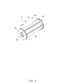
- FIG. 1 is a perspective view showing the configuration of a high-frequency quadrupole linear accelerator according to this embodiment;
- FIG. 1 is an exploded perspective view showing the configuration of a high-frequency quadrupole linear accelerator according to this embodiment;
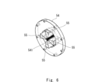
- FIG. 4 is a perspective view showing a configuration of a connection flange that connects tubular members;
- FIG. 1 is a block diagram showing, as an example, a schematic configuration of a compact neutron source system according to this embodiment.
- a radio frequency quadrupole (RFQ) 3 according to this embodiment is configured as a particle accelerator used in the neutron source system 1, as shown in FIG.
- a neutron source system 1 according to this embodiment includes an ion source 2 , a high frequency quadrupole linear accelerator 3 , and a target station 4 .
- the ion source 2 is provided with, for example, a vacuum pump and a magnetron.
- the ion source 2 may be configured as a microwave ion source.
- the ion source 2 generates ions (eg, protons H + of hydrogen ions) by, for example, ionizing a solid or gas to generate plasma and extracting ions by an electric field.
- the high-frequency quadrupole linear accelerator 3 is a high-frequency linear accelerator.
- the high-frequency quadrupole linear accelerator 3 can simultaneously focus and accelerate an ion beam with a high-frequency electric field.
- a high-frequency quadrupole linear accelerator 3 is suitable for accelerating low-energy ion beams immediately after the ion source 2 .
- the high-frequency quadrupole linear accelerator 3 applies high-frequency waves to four opposing electrodes to generate a quadrupole electric field, thereby focusing and accelerating the ions generated by the ion source 2 .
- the high frequency quadrupole linear accelerator 3 can accelerate ions up to, for example, 2.49 MeV.
- a DTL (Drift Tube Linac) that further focuses and accelerates ions may be provided after the high-frequency quadrupole linear accelerator 3 .
- the high-frequency quadrupole linear accelerator 3 may also be used as an injector (pre-accelerator) for a cyclotron, synchrotron, or the like, or may be used in a medium- or large-sized neutron source system.
- the target station 4 contains neutron generating target materials such as lithium Li and beryllium Be inside.
- neutron generating target materials such as lithium Li and beryllium Be inside.
- lithium Li as the neutron generation target material.
- the ions accelerated by the high frequency quadrupole linear accelerator 3 collide with the neutron generating target material in the target station 4 and generate neutrons through nuclear reactions.
- the target station 4 then emits the generated neutrons as a neutron beam. Using this neutron beam, for example, non-destructive inspection can be performed. Note that the distance to the neutron generation target material may be set arbitrarily.
- FIG. 2 is a perspective view showing the configuration of the high-frequency quadrupole linear accelerator according to this embodiment.
- FIG. 3 is an exploded perspective view showing the configuration of the high-frequency quadrupole linear accelerator according to this embodiment.
- the high-frequency quadrupole linear accelerator 3 according to the present embodiment includes a tubular casing 31, four first vane electrodes 32, and front and rear end plates 33 and 34. As shown in FIG.
- the cylindrical housing portion 31 has a substantially cylindrical cylindrical portion 311 and annular flange portions 312 connected to the front end and the rear end of the cylindrical portion 311, respectively.
- the cylindrical portion 311 and the flange portion 312 are integrally molded.
- the tubular housing portion 31 is made of, for example, iron having high rigidity as a base material.
- the inside of the acceleration cavity of the tubular casing 31 is plated with copper having high electrical conductivity, for example. Note that the cylindrical housing portion 31 may be made by cutting oxygen-free copper.
- the inside of the cylindrical housing portion 31 is evacuated.
- a vacuum port, a coupler port, a pickup port, and the like may be provided on the outer peripheral surface of the cylindrical portion 311 .
- the first vane electrode 32 is inserted into the opening 313 of the tubular casing 31 from the outside toward the center of the axis.
- the first vane electrode 32 includes an electrode portion 321 formed on the front end side and having a substantially triangular cross section, a fitting portion 322 formed on the rear end side and fitted into the opening 313 of the cylindrical casing portion 31, consists of The electrode portion 321 and the fitting portion 322 are integrally formed.
- the fitting portion 322 of the first vane electrode 32 fits into the opening portion 313 of the cylindrical housing portion 31 and is detachably attached to the opening portion 313 by, for example, bolts.
- Each pair of first vane electrodes 32 is arranged to face each other.
- the tip of the electrode portion 321 of the first vane electrode 32 is formed in a wavy shape in the longitudinal direction.
- the wave shape of the tip portion of the electrode portion 321 of the first vane electrode 32 is simplified.
- the first vane electrodes 32 are arranged to face each other perpendicularly along the beam acceleration axis. Further, the first vane electrodes 32 facing each other are arranged such that the peaks face each other and the valleys face each other, and the peaks and valleys of adjacent first vane electrodes 32 that are separated from each other by 90 degrees are adjacent to each other.
- first vane electrodes 32 one pair of first vane electrodes 32 and the other pair of first vane electrodes 32 are supplied with high-frequency power such that the signs are different from each other.
- the cylindrical housing portion 31 and the first vane electrode 32 form a high frequency cavity resonator.
- high-frequency electric power having a frequency equal to the resonance frequency of the resonator is supplied to the tubular casing 31 and the first vane electrode 32 , a high-frequency voltage is generated in the first vane electrode 32 .
- a front end plate 33 is provided at the front end of the tubular housing portion 31 so as to close the front end of the tubular housing portion 31 .
- the front end plate 33 is detachably attached to the front end of the cylindrical housing portion 31 with bolts or the like.
- the front end plate 33 is a substantially circular plate-like member, and has a through hole 331 formed in its center. The ion beam accelerated by the high-frequency quadrupole electric field inside the tubular casing 31 is emitted from the through hole 331 of the front end plate 33 .
- a rear end plate 34 is provided at the rear end of the tubular housing portion 31 so as to close the rear end of the tubular housing portion 31 .
- the rear end plate 34 is detachably attached to the rear end of the cylindrical housing portion 31 with bolts or the like.
- the rear end plate 34 is a substantially circular plate-like member and has a through hole formed in its center.
- At least one of the front end plate 33 and the rear end plate 34 may be formed integrally with the tubular housing portion 31 .
- front and rear end plates 33 and 34 are detachably provided at the front end and the rear end of the cylindrical housing portion 31, so that the front end and the rear end of the cylindrical housing portion 31 can be mounted. It is possible to improve the connectivity of other members to.
- each first vane electrode 32 is inserted into the opening 313 of the cylindrical casing 31 from the outside toward the center of the axis. , are detachably attached to the opening 313 and arranged to face each other.
- first vane electrodes 32 are activated or damaged and need to be replaced, only the activated or damaged first vane electrodes 32 can be placed in the tubular housing. It can be easily removed from the opening 313 of the body 31 and a new first vane electrode 32 can be attached.
- each first vane electrode 32 is inserted into the opening 313 of the tubular housing 31 from the outside toward the center of the axis.
- the first vane electrode 32 that needs to be replaced can be easily accessed from the outside and removed, and a new first vane electrode 32 can be attached. Therefore, the maintainability of the high-frequency quadrupole linear accelerator 3 can be improved.
- front and rear end plates 33 and 34 may be detachably provided at the front and rear ends of the cylindrical housing portion 31, respectively, as described above.
- front or rear end plates 33, 34 when the front or rear end plates 33, 34 are activated or damaged and need to be replaced, only the activated or damaged front or rear end plates 33, 34 can be placed in the tubular housing. It can be easily removed from body 31 and new front or rear endplates 33, 34 can be installed. Therefore, the maintainability of the high-frequency quadrupole linear accelerator 3 can be further improved.
- the tubular casing 31, the four first vane electrodes 32, and the front and rear end plates 33 and 34 are manufactured.
- the cylindrical housing portion 31 is manufactured by, for example, cutting out a base material such as iron using a machine tool and plating the surface with copper.
- first vane electrodes 32 are inserted into the opening 313 of the tubular casing 31 from the outside toward the axial center, fitted into the opening 313, and arranged to face each other. Then, each of the first vane electrodes 32 is connected and fixed to the opening 313 of the tubular housing 31 with a bolt or the like.
- the front and rear end plates 33 and 34 are connected to the front and rear ends of the tubular casing 31 with bolts or the like, respectively. Note that the front and rear end plates 33 and 34 may be connected to the tubular casing 31 before the first vane electrode 32 is connected.
- the high-frequency quadrupole linear accelerator 3 includes the cylindrical casing portion 31 formed so that the two pairs of openings 313 extending in the axial direction on the outer peripheral surface are opposed to each other, and the cylindrical casing portion 31 a plurality of first vane electrodes 32 that are inserted into the opening 313 of the body 31 toward the center of the axis from the outside, are detachably fitted in the opening 313, and are arranged to face each other; ing.
- first vane electrode 32 that needs to be replaced can be easily removed from the opening 313 of the tubular casing 31, and a new first vane electrode 32 can be attached. Furthermore, the first vane electrode 32 that needs to be replaced can be easily accessed from the outside and removed, and a new first vane electrode 32 can be attached. Therefore, the maintainability of the high-frequency quadrupole linear accelerator 3 can be improved.
- each member is connected by screws such as bolts, so the above problems (1) to (3) may occur. do not have.
- the main manufacturing process is only assembly by machining and bolting, so the manufacturing cost is suppressed, and the acceleration cavity body is divided into the entire length and the longitudinal direction.
- ⁇ The internal electrodes (vanes) for frequency adjustment can be easily processed (shaving and polishing), making subsequent adjustments easy. It enables electric field distribution adjustment that realizes highly efficient acceleration. ⁇ It is also possible to retrofit the cooling function to the incident/outgoing parts that require cooling (such as attaching to the flange).
- ⁇ As for the base material there is a degree of freedom as needed, such as cutting from copper and copper plating on the iron base material.
- FIG. 4 is a perspective view showing the configuration of the high-frequency quadrupole linear accelerator according to this embodiment.
- FIG. 5 is an exploded perspective view showing the configuration of the high-frequency quadrupole linear accelerator according to this embodiment.
- the tubular housing portion may be configured by coaxially connecting a plurality of tubular members 51 .
- the tubular casing may be configured by coaxially connecting three tubular members 51 .
- the tubular member 51 has two pairs of axially extending openings 511 formed on the outer peripheral surface thereof so as to face each other with a phase difference of 90°.
- the first vane electrodes 53 are inserted into the openings 511 of the cylindrical member 51 from the outside toward the axial center, are detachably fitted into the openings 511, and are arranged to face each other.
- FIG. 6 is a perspective view showing the configuration of a connection flange that connects each cylindrical member.
- Each tubular member 51 is coaxially connected via a connection flange 54 .
- the connection flange 54 is a substantially annular plate member having a through hole 541 formed in the center.
- Each tubular member 51 and the connection flange 54 are connected by bolts or the like.
- the cross section of the through-hole 541 is, for example, substantially octagonal.
- Two pairs of second vane electrodes 55 facing each other with a phase difference of 90° are provided in the through holes 541 of the connection flange 54 .
- Each second vane electrode 55 is detachably connected to a through hole 541 of the connection flange 54 by a bolt or the like.
- the connection flange 54 and the second vane electrode 55 may be formed integrally.
- the second vane electrodes 55 are arranged between adjacent first vane electrodes 53 and connect the first vane electrodes 53 at both ends thereof. Thereby, the second vane electrode 55 and the respective first vane electrodes 53 on both ends thereof are continuously connected in the axial direction.
- the cylindrical member 51, the connection flange 54, the first vane electrode 53, and the second vane electrode 55 form a high frequency cavity resonator, and high frequency voltages are generated in the first and second vane electrodes 53,55.
- An ion beam is incident on the central portion surrounded by the first and second vane electrodes 53 and 55.
- the ion beam is focused and accelerated by the high-frequency quadrupole electric field and emitted as a high-energy ion beam. .
- a front end plate 56 is provided at the front end of the front tubular member 51 so as to close the front end of the front tubular member 51 .
- the front end plate 56 is detachably attached to the front end of the front tubular member 51 with a bolt or the like.
- the ion beam accelerated by the high frequency quadrupole electric field inside the cylindrical member 51 is emitted from the through hole 561 of the front end plate 56 .
- a rear end plate 57 is provided at the rear end of the rear tubular member 51 so as to block the rear end of the rear tubular member 51 .
- the rear end plate 57 is detachably attached to the rear end of the rear cylindrical member 51 by bolts or the like.
- the tubular casing is configured by connecting a plurality of tubular members 51 .
- each cylindrical member 51 can be miniaturized, and a processing machine or the like for manufacturing each cylindrical member 51 can be miniaturized. Therefore, manufacturing costs can be reduced.
- the total length of the cylindrical housing is about 2-3m, and a large processing machine is required to cut it out from a large base material.
- the cylindrical housing portion is composed of three cylindrical members 51
- the total length of each cylindrical member 31 is about 1 m, and each cylindrical member 31 can be machined by a small processing machine. Therefore, each cylindrical member 31 can be manufactured at low cost using a small processing machine.
- the total length of the tubular casing may be as short as, for example, about 30 cm or 50 cm.
- tubular members 51 constituting the tubular casing when some of the tubular members 51 constituting the tubular casing are activated or damaged, only the activated or damaged tubular member 51 can be easily removed. , a new tubular member 51 can be attached.
- first and second vane electrodes 53 and 55 when some of the first and second vane electrodes 53 and 55 are activated or damaged, the activated or damaged first and second vane electrodes 53 and 55 Only the vane electrodes 53, 55 can be easily removed and new first and second vane electrodes 53, 55 can be attached. In this way, only the activated or damaged parts can be partially replaced, and the maintainability of the high-frequency quadrupole linear accelerator 20 can be improved.
- the tubular housing portion is configured by coaxially connecting three tubular members 51, but it is not limited to this.
- the number of tubular members 51 to be connected may be, for example, two or four or more, and may be arbitrary.
- the total length of the tubular member 51 may be determined according to the size of the existing processing machine, and the number of tubular members 51 may be determined according to the total length.
- all members including the cylindrical housing, may be plated with copper, which has high electrical conductivity, on a metal base material, or may be made of machined oxygen-free copper.
Landscapes
- Physics & Mathematics (AREA)
- Spectroscopy & Molecular Physics (AREA)
- Engineering & Computer Science (AREA)
- Plasma & Fusion (AREA)
- High Energy & Nuclear Physics (AREA)
- Particle Accelerators (AREA)
Priority Applications (1)
| Application Number | Priority Date | Filing Date | Title |
|---|---|---|---|
| JP2023550496A JP7579610B2 (ja) | 2021-09-30 | 2022-09-06 | 高周波四重極線形加速器、中性子源システム及び高周波四重極線形加速器の製造方法 |
Applications Claiming Priority (2)
| Application Number | Priority Date | Filing Date | Title |
|---|---|---|---|
| JP2021-160864 | 2021-09-30 | ||
| JP2021160864 | 2021-09-30 |
Publications (1)
| Publication Number | Publication Date |
|---|---|
| WO2023053858A1 true WO2023053858A1 (ja) | 2023-04-06 |
Family
ID=85782361
Family Applications (1)
| Application Number | Title | Priority Date | Filing Date |
|---|---|---|---|
| PCT/JP2022/033355 Ceased WO2023053858A1 (ja) | 2021-09-30 | 2022-09-06 | 高周波四重極線形加速器、中性子源システム及び高周波四重極線形加速器の製造方法 |
Country Status (2)
| Country | Link |
|---|---|
| JP (1) | JP7579610B2 (https=) |
| WO (1) | WO2023053858A1 (https=) |
Citations (5)
| Publication number | Priority date | Publication date | Assignee | Title |
|---|---|---|---|---|
| JPH0173800U (https=) * | 1987-05-28 | 1989-05-18 | ||
| JPH0196700U (https=) * | 1987-12-21 | 1989-06-27 | ||
| JPH06290900A (ja) * | 1993-03-31 | 1994-10-18 | Kobe Steel Ltd | 高周波四重極加速装置 |
| JP2011086494A (ja) * | 2009-10-15 | 2011-04-28 | Tokyo Institute Of Technology | 四重極型加速器および四重極型加速器の製造方法 |
| JP2011086498A (ja) * | 2009-10-15 | 2011-04-28 | Tokyo Institute Of Technology | 高周波加速器および高周波加速器の製造方法 |
-
2022
- 2022-09-06 WO PCT/JP2022/033355 patent/WO2023053858A1/ja not_active Ceased
- 2022-09-06 JP JP2023550496A patent/JP7579610B2/ja active Active
Patent Citations (5)
| Publication number | Priority date | Publication date | Assignee | Title |
|---|---|---|---|---|
| JPH0173800U (https=) * | 1987-05-28 | 1989-05-18 | ||
| JPH0196700U (https=) * | 1987-12-21 | 1989-06-27 | ||
| JPH06290900A (ja) * | 1993-03-31 | 1994-10-18 | Kobe Steel Ltd | 高周波四重極加速装置 |
| JP2011086494A (ja) * | 2009-10-15 | 2011-04-28 | Tokyo Institute Of Technology | 四重極型加速器および四重極型加速器の製造方法 |
| JP2011086498A (ja) * | 2009-10-15 | 2011-04-28 | Tokyo Institute Of Technology | 高周波加速器および高周波加速器の製造方法 |
Also Published As
| Publication number | Publication date |
|---|---|
| JP7579610B2 (ja) | 2024-11-08 |
| JPWO2023053858A1 (https=) | 2023-04-06 |
Similar Documents
| Publication | Publication Date | Title |
|---|---|---|
| US12127327B2 (en) | Compact linear accelerator with accelerating waveguide | |
| RU2316157C2 (ru) | Линейный ускоритель для ускорения пучка ионов | |
| CN112098734A (zh) | 高精密电磁组合测量方法及基于该方法的负氢回旋加速器 | |
| US12324088B2 (en) | Ion source, circular accelerator using same, and particle beam therapy system | |
| CN101778527A (zh) | 外置阴极独立调谐微波电子枪 | |
| US6327339B1 (en) | Industrial x-ray/electron beam source using an electron accelerator | |
| Jongen et al. | The Rhodotron, a new 10 MeV, 100 kW, cw metric wave electron accelerator | |
| JP2013508922A (ja) | 低電圧マルチビームクライストロン | |
| O'shea et al. | Initial results from the Los Alamos photoinjector-driven free-electron laser | |
| WO2023053858A1 (ja) | 高周波四重極線形加速器、中性子源システム及び高周波四重極線形加速器の製造方法 | |
| US5568021A (en) | Electrostatic accelerator up to 200 kV | |
| JP6736452B2 (ja) | 線形加速装置、中性子ビーム生成装置及び粒子線治療装置 | |
| Larionov et al. | Design of multi-beam klystron in X-band | |
| Nozdrin et al. | Linac-200: A new electron test beam facility at JINR | |
| Staples | The NSNS front end accelerator system | |
| WO2018096648A1 (ja) | 加速器および粒子線照射装置 | |
| KR20190033868A (ko) | 붕소 중성자 포획방식의 암치료를 위한 양성자 선형 가속기 | |
| Nakanishi et al. | Construction and operation of a test RFQ linac for heavy ions | |
| Chi et al. | Design studies on 100 MeV/100 KW electron linac for NSC KIPT neutron source on the base of subcritical assembly driven by linac | |
| JP2019096543A (ja) | 粒子加速器、粒子加速システム、及び粒子線治療装置 | |
| Oshatz et al. | Mechanical Design of the SNS MEBT | |
| Kondrashev et al. | Acceleration of intense beams of highly charged ions using direct plasma injection scheme | |
| Zhang et al. | Coaxial integrated linear accelerator powered by a high-efficiency and high-power transit-time oscillator | |
| JP2024154026A (ja) | 加速器及び加速システム | |
| CN118042697A (zh) | 一种集成微波源的粒子加速器 |
Legal Events
| Date | Code | Title | Description |
|---|---|---|---|
| 121 | Ep: the epo has been informed by wipo that ep was designated in this application |
Ref document number: 22875730 Country of ref document: EP Kind code of ref document: A1 |
|
| WWE | Wipo information: entry into national phase |
Ref document number: 2023550496 Country of ref document: JP |
|
| NENP | Non-entry into the national phase |
Ref country code: DE |
|
| 122 | Ep: pct application non-entry in european phase |
Ref document number: 22875730 Country of ref document: EP Kind code of ref document: A1 |