WO2023053858A1 - 高周波四重極線形加速器、中性子源システム及び高周波四重極線形加速器の製造方法 - Google Patents
高周波四重極線形加速器、中性子源システム及び高周波四重極線形加速器の製造方法 Download PDFInfo
- Publication number
- WO2023053858A1 WO2023053858A1 PCT/JP2022/033355 JP2022033355W WO2023053858A1 WO 2023053858 A1 WO2023053858 A1 WO 2023053858A1 JP 2022033355 W JP2022033355 W JP 2022033355W WO 2023053858 A1 WO2023053858 A1 WO 2023053858A1
- Authority
- WO
- WIPO (PCT)
- Prior art keywords
- linear accelerator
- frequency quadrupole
- quadrupole linear
- cylindrical
- openings
- Prior art date
Links
- 238000004519 manufacturing process Methods 0.000 title claims description 16
- 238000000034 method Methods 0.000 title claims description 8
- 150000002500 ions Chemical class 0.000 claims description 25
- 230000002093 peripheral effect Effects 0.000 claims description 12
- 239000013077 target material Substances 0.000 claims description 8
- 238000006243 chemical reaction Methods 0.000 claims description 3
- 230000001133 acceleration Effects 0.000 description 10
- 238000010884 ion-beam technique Methods 0.000 description 10
- 230000005684 electric field Effects 0.000 description 8
- RYGMFSIKBFXOCR-UHFFFAOYSA-N Copper Chemical compound [Cu] RYGMFSIKBFXOCR-UHFFFAOYSA-N 0.000 description 7
- 229910052802 copper Inorganic materials 0.000 description 7
- 239000010949 copper Substances 0.000 description 7
- 239000000463 material Substances 0.000 description 7
- 238000012545 processing Methods 0.000 description 7
- XEEYBQQBJWHFJM-UHFFFAOYSA-N Iron Chemical compound [Fe] XEEYBQQBJWHFJM-UHFFFAOYSA-N 0.000 description 6
- 238000005219 brazing Methods 0.000 description 3
- 238000005520 cutting process Methods 0.000 description 3
- 229910052742 iron Inorganic materials 0.000 description 3
- 239000002245 particle Substances 0.000 description 3
- WHXSMMKQMYFTQS-UHFFFAOYSA-N Lithium Chemical compound [Li] WHXSMMKQMYFTQS-UHFFFAOYSA-N 0.000 description 2
- 238000001816 cooling Methods 0.000 description 2
- 238000010586 diagram Methods 0.000 description 2
- 229910052744 lithium Inorganic materials 0.000 description 2
- 238000012986 modification Methods 0.000 description 2
- 230000004048 modification Effects 0.000 description 2
- 238000007747 plating Methods 0.000 description 2
- 230000004913 activation Effects 0.000 description 1
- 230000008901 benefit Effects 0.000 description 1
- 229910052790 beryllium Inorganic materials 0.000 description 1
- ATBAMAFKBVZNFJ-UHFFFAOYSA-N beryllium atom Chemical compound [Be] ATBAMAFKBVZNFJ-UHFFFAOYSA-N 0.000 description 1
- 238000012937 correction Methods 0.000 description 1
- 230000001066 destructive effect Effects 0.000 description 1
- 238000009826 distribution Methods 0.000 description 1
- 239000007789 gas Substances 0.000 description 1
- 239000001257 hydrogen Substances 0.000 description 1
- 229910052739 hydrogen Inorganic materials 0.000 description 1
- -1 hydrogen ions Chemical class 0.000 description 1
- 238000007689 inspection Methods 0.000 description 1
- 238000003754 machining Methods 0.000 description 1
- 238000012423 maintenance Methods 0.000 description 1
- 229910052751 metal Inorganic materials 0.000 description 1
- 239000002184 metal Substances 0.000 description 1
- 238000005498 polishing Methods 0.000 description 1
- 230000005855 radiation Effects 0.000 description 1
- 230000008439 repair process Effects 0.000 description 1
- 239000007787 solid Substances 0.000 description 1
Images


Classifications
-
- H—ELECTRICITY
- H05—ELECTRIC TECHNIQUES NOT OTHERWISE PROVIDED FOR
- H05H—PLASMA TECHNIQUE; PRODUCTION OF ACCELERATED ELECTRICALLY-CHARGED PARTICLES OR OF NEUTRONS; PRODUCTION OR ACCELERATION OF NEUTRAL MOLECULAR OR ATOMIC BEAMS
- H05H13/00—Magnetic resonance accelerators; Cyclotrons
- H05H13/04—Synchrotrons
-
- H—ELECTRICITY
- H05—ELECTRIC TECHNIQUES NOT OTHERWISE PROVIDED FOR
- H05H—PLASMA TECHNIQUE; PRODUCTION OF ACCELERATED ELECTRICALLY-CHARGED PARTICLES OR OF NEUTRONS; PRODUCTION OR ACCELERATION OF NEUTRAL MOLECULAR OR ATOMIC BEAMS
- H05H3/00—Production or acceleration of neutral particle beams, e.g. molecular or atomic beams
- H05H3/06—Generating neutron beams
-
- H—ELECTRICITY
- H05—ELECTRIC TECHNIQUES NOT OTHERWISE PROVIDED FOR
- H05H—PLASMA TECHNIQUE; PRODUCTION OF ACCELERATED ELECTRICALLY-CHARGED PARTICLES OR OF NEUTRONS; PRODUCTION OR ACCELERATION OF NEUTRAL MOLECULAR OR ATOMIC BEAMS
- H05H9/00—Linear accelerators
Definitions
- the present invention relates to a high-frequency quadrupole linear accelerator, a neutron source system, and a method for manufacturing a high-frequency quadrupole linear accelerator.
- a high-frequency quadrupole linear accelerator for accelerating charged particles such as ions or electrons is known (see Patent Document 1, for example).
- a high-frequency quadrupole linear accelerator includes four electrodes and a tubular section. Each electrode is integrally formed with the tubular portion.
- the electrodes For example, if some of the electrodes are activated or damaged, the electrodes need to be replaced. In the high-frequency quadrupole linear accelerator, the electrodes and the cylindrical portion are integrally molded. For this reason, not only the electrodes but also the cylindrical portion must be replaced at the same time. Also, when adjusting the acceleration energy, for example, for purposes other than activation or failure, it is necessary to adjust not only the electrodes but also the cylindrical portion at the same time, resulting in low maintainability. .
- the present invention has been made to solve such problems, and the main object thereof is to provide a high-frequency quadrupole linear accelerator, a neutron source system, and a method of manufacturing a high-frequency quadrupole linear accelerator with improved maintainability.
- One aspect of the present invention for achieving the above object is a cylindrical housing portion formed so that two pairs of axially extending openings on the outer peripheral surface are opposed to each other; a plurality of first vane electrodes that are inserted into the opening of the cylindrical casing from the outside toward the center of the axis, are detachably attached to the opening, and are arranged to face each other; comprising It is a high frequency quadrupole linear accelerator.
- the cylindrical housing portion is configured by coaxially connecting a plurality of cylindrical members each having two pairs of openings extending in the axial direction on the outer peripheral surface thereof facing each other,
- the first vane electrodes may be inserted into the openings of the tubular member from the outside toward the axial center, detachably attached to the openings, and arranged to face each other.
- the cylindrical members are coaxially connected via a connection flange having a through hole formed in the center, two pairs of second vane electrodes facing each other are detachably provided in the through holes of the connection flange,
- the second vane electrodes may be arranged between the adjacent first vane electrodes and connect the first vane electrodes.
- a front end plate having a through hole formed in the center thereof is detachably provided at the front end of the tubular casing so as to block the front end
- a rear end plate having a through hole formed in the center may be detachably provided at the rear end of the cylindrical member so as to block the rear end.
- One aspect of the present invention for achieving the above object is an ion source that produces ions; a radio frequency quadrupole linear accelerator as described above for accelerating ions produced by the ion source; a target station containing a neutron generation target material therein, in which ions accelerated by the high-frequency quadrupole linear accelerator collide with the neutron generation target material to generate neutrons through a nuclear reaction; comprising It may be a neutron source system.
- One aspect of the present invention for achieving the above object is a step of forming a cylindrical housing portion formed so that two pairs of axially extending openings are formed on the outer peripheral surface so as to face each other; a step of inserting the first vane electrodes into the opening of the tubular casing from the outside toward the axial center, detachably attaching them to the opening, and arranging them so as to face each other; including, A method for manufacturing a high frequency quadrupole linear accelerator.
- the first vane electrodes may be inserted into the openings of the cylindrical member from the outside toward the axial center, detachably attached to the openings, and arranged to face each other.
- the present invention it is possible to provide a high-frequency quadrupole linear accelerator, a neutron source system, and a method for manufacturing a high-frequency quadrupole linear accelerator with improved maintainability.
- FIG. 1 is a block diagram showing a schematic configuration of a neutron source system according to this embodiment;
- FIG. 1 is a perspective view showing the configuration of a high-frequency quadrupole linear accelerator according to this embodiment;
- FIG. 1 is an exploded perspective view showing the configuration of a high-frequency quadrupole linear accelerator according to this embodiment;
- FIG. 1 is a perspective view showing the configuration of a high-frequency quadrupole linear accelerator according to this embodiment;
- FIG. 1 is an exploded perspective view showing the configuration of a high-frequency quadrupole linear accelerator according to this embodiment;
- FIG. 4 is a perspective view showing a configuration of a connection flange that connects tubular members;
- FIG. 1 is a block diagram showing, as an example, a schematic configuration of a compact neutron source system according to this embodiment.
- a radio frequency quadrupole (RFQ) 3 according to this embodiment is configured as a particle accelerator used in the neutron source system 1, as shown in FIG.
- a neutron source system 1 according to this embodiment includes an ion source 2 , a high frequency quadrupole linear accelerator 3 , and a target station 4 .
- the ion source 2 is provided with, for example, a vacuum pump and a magnetron.
- the ion source 2 may be configured as a microwave ion source.
- the ion source 2 generates ions (eg, protons H + of hydrogen ions) by, for example, ionizing a solid or gas to generate plasma and extracting ions by an electric field.
- the high-frequency quadrupole linear accelerator 3 is a high-frequency linear accelerator.
- the high-frequency quadrupole linear accelerator 3 can simultaneously focus and accelerate an ion beam with a high-frequency electric field.
- a high-frequency quadrupole linear accelerator 3 is suitable for accelerating low-energy ion beams immediately after the ion source 2 .
- the high-frequency quadrupole linear accelerator 3 applies high-frequency waves to four opposing electrodes to generate a quadrupole electric field, thereby focusing and accelerating the ions generated by the ion source 2 .
- the high frequency quadrupole linear accelerator 3 can accelerate ions up to, for example, 2.49 MeV.
- a DTL (Drift Tube Linac) that further focuses and accelerates ions may be provided after the high-frequency quadrupole linear accelerator 3 .
- the high-frequency quadrupole linear accelerator 3 may also be used as an injector (pre-accelerator) for a cyclotron, synchrotron, or the like, or may be used in a medium- or large-sized neutron source system.
- the target station 4 contains neutron generating target materials such as lithium Li and beryllium Be inside.
- neutron generating target materials such as lithium Li and beryllium Be inside.
- lithium Li as the neutron generation target material.
- the ions accelerated by the high frequency quadrupole linear accelerator 3 collide with the neutron generating target material in the target station 4 and generate neutrons through nuclear reactions.
- the target station 4 then emits the generated neutrons as a neutron beam. Using this neutron beam, for example, non-destructive inspection can be performed. Note that the distance to the neutron generation target material may be set arbitrarily.
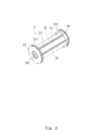
- FIG. 2 is a perspective view showing the configuration of the high-frequency quadrupole linear accelerator according to this embodiment.
- FIG. 3 is an exploded perspective view showing the configuration of the high-frequency quadrupole linear accelerator according to this embodiment.
- the high-frequency quadrupole linear accelerator 3 according to the present embodiment includes a tubular casing 31, four first vane electrodes 32, and front and rear end plates 33 and 34. As shown in FIG.
- the cylindrical housing portion 31 has a substantially cylindrical cylindrical portion 311 and annular flange portions 312 connected to the front end and the rear end of the cylindrical portion 311, respectively.
- the cylindrical portion 311 and the flange portion 312 are integrally molded.
- the tubular housing portion 31 is made of, for example, iron having high rigidity as a base material.
- the inside of the acceleration cavity of the tubular casing 31 is plated with copper having high electrical conductivity, for example. Note that the cylindrical housing portion 31 may be made by cutting oxygen-free copper.
- the inside of the cylindrical housing portion 31 is evacuated.
- a vacuum port, a coupler port, a pickup port, and the like may be provided on the outer peripheral surface of the cylindrical portion 311 .
- the first vane electrode 32 is inserted into the opening 313 of the tubular casing 31 from the outside toward the center of the axis.
- the first vane electrode 32 includes an electrode portion 321 formed on the front end side and having a substantially triangular cross section, a fitting portion 322 formed on the rear end side and fitted into the opening 313 of the cylindrical casing portion 31, consists of The electrode portion 321 and the fitting portion 322 are integrally formed.
- the fitting portion 322 of the first vane electrode 32 fits into the opening portion 313 of the cylindrical housing portion 31 and is detachably attached to the opening portion 313 by, for example, bolts.
- Each pair of first vane electrodes 32 is arranged to face each other.
- the tip of the electrode portion 321 of the first vane electrode 32 is formed in a wavy shape in the longitudinal direction.
- the wave shape of the tip portion of the electrode portion 321 of the first vane electrode 32 is simplified.
- the first vane electrodes 32 are arranged to face each other perpendicularly along the beam acceleration axis. Further, the first vane electrodes 32 facing each other are arranged such that the peaks face each other and the valleys face each other, and the peaks and valleys of adjacent first vane electrodes 32 that are separated from each other by 90 degrees are adjacent to each other.
- first vane electrodes 32 one pair of first vane electrodes 32 and the other pair of first vane electrodes 32 are supplied with high-frequency power such that the signs are different from each other.
- the cylindrical housing portion 31 and the first vane electrode 32 form a high frequency cavity resonator.
- high-frequency electric power having a frequency equal to the resonance frequency of the resonator is supplied to the tubular casing 31 and the first vane electrode 32 , a high-frequency voltage is generated in the first vane electrode 32 .
- a front end plate 33 is provided at the front end of the tubular housing portion 31 so as to close the front end of the tubular housing portion 31 .
- the front end plate 33 is detachably attached to the front end of the cylindrical housing portion 31 with bolts or the like.
- the front end plate 33 is a substantially circular plate-like member, and has a through hole 331 formed in its center. The ion beam accelerated by the high-frequency quadrupole electric field inside the tubular casing 31 is emitted from the through hole 331 of the front end plate 33 .
- a rear end plate 34 is provided at the rear end of the tubular housing portion 31 so as to close the rear end of the tubular housing portion 31 .
- the rear end plate 34 is detachably attached to the rear end of the cylindrical housing portion 31 with bolts or the like.
- the rear end plate 34 is a substantially circular plate-like member and has a through hole formed in its center.
- At least one of the front end plate 33 and the rear end plate 34 may be formed integrally with the tubular housing portion 31 .
- front and rear end plates 33 and 34 are detachably provided at the front end and the rear end of the cylindrical housing portion 31, so that the front end and the rear end of the cylindrical housing portion 31 can be mounted. It is possible to improve the connectivity of other members to.
- each first vane electrode 32 is inserted into the opening 313 of the cylindrical casing 31 from the outside toward the center of the axis. , are detachably attached to the opening 313 and arranged to face each other.
- first vane electrodes 32 are activated or damaged and need to be replaced, only the activated or damaged first vane electrodes 32 can be placed in the tubular housing. It can be easily removed from the opening 313 of the body 31 and a new first vane electrode 32 can be attached.
- each first vane electrode 32 is inserted into the opening 313 of the tubular housing 31 from the outside toward the center of the axis.
- the first vane electrode 32 that needs to be replaced can be easily accessed from the outside and removed, and a new first vane electrode 32 can be attached. Therefore, the maintainability of the high-frequency quadrupole linear accelerator 3 can be improved.
- front and rear end plates 33 and 34 may be detachably provided at the front and rear ends of the cylindrical housing portion 31, respectively, as described above.
- front or rear end plates 33, 34 when the front or rear end plates 33, 34 are activated or damaged and need to be replaced, only the activated or damaged front or rear end plates 33, 34 can be placed in the tubular housing. It can be easily removed from body 31 and new front or rear endplates 33, 34 can be installed. Therefore, the maintainability of the high-frequency quadrupole linear accelerator 3 can be further improved.
- the tubular casing 31, the four first vane electrodes 32, and the front and rear end plates 33 and 34 are manufactured.
- the cylindrical housing portion 31 is manufactured by, for example, cutting out a base material such as iron using a machine tool and plating the surface with copper.
- first vane electrodes 32 are inserted into the opening 313 of the tubular casing 31 from the outside toward the axial center, fitted into the opening 313, and arranged to face each other. Then, each of the first vane electrodes 32 is connected and fixed to the opening 313 of the tubular housing 31 with a bolt or the like.
- the front and rear end plates 33 and 34 are connected to the front and rear ends of the tubular casing 31 with bolts or the like, respectively. Note that the front and rear end plates 33 and 34 may be connected to the tubular casing 31 before the first vane electrode 32 is connected.
- the high-frequency quadrupole linear accelerator 3 includes the cylindrical casing portion 31 formed so that the two pairs of openings 313 extending in the axial direction on the outer peripheral surface are opposed to each other, and the cylindrical casing portion 31 a plurality of first vane electrodes 32 that are inserted into the opening 313 of the body 31 toward the center of the axis from the outside, are detachably fitted in the opening 313, and are arranged to face each other; ing.
- first vane electrode 32 that needs to be replaced can be easily removed from the opening 313 of the tubular casing 31, and a new first vane electrode 32 can be attached. Furthermore, the first vane electrode 32 that needs to be replaced can be easily accessed from the outside and removed, and a new first vane electrode 32 can be attached. Therefore, the maintainability of the high-frequency quadrupole linear accelerator 3 can be improved.
- each member is connected by screws such as bolts, so the above problems (1) to (3) may occur. do not have.
- the main manufacturing process is only assembly by machining and bolting, so the manufacturing cost is suppressed, and the acceleration cavity body is divided into the entire length and the longitudinal direction.
- ⁇ The internal electrodes (vanes) for frequency adjustment can be easily processed (shaving and polishing), making subsequent adjustments easy. It enables electric field distribution adjustment that realizes highly efficient acceleration. ⁇ It is also possible to retrofit the cooling function to the incident/outgoing parts that require cooling (such as attaching to the flange).
- ⁇ As for the base material there is a degree of freedom as needed, such as cutting from copper and copper plating on the iron base material.
- FIG. 4 is a perspective view showing the configuration of the high-frequency quadrupole linear accelerator according to this embodiment.
- FIG. 5 is an exploded perspective view showing the configuration of the high-frequency quadrupole linear accelerator according to this embodiment.
- the tubular housing portion may be configured by coaxially connecting a plurality of tubular members 51 .
- the tubular casing may be configured by coaxially connecting three tubular members 51 .
- the tubular member 51 has two pairs of axially extending openings 511 formed on the outer peripheral surface thereof so as to face each other with a phase difference of 90°.
- the first vane electrodes 53 are inserted into the openings 511 of the cylindrical member 51 from the outside toward the axial center, are detachably fitted into the openings 511, and are arranged to face each other.
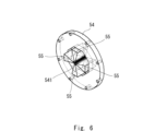
- FIG. 6 is a perspective view showing the configuration of a connection flange that connects each cylindrical member.
- Each tubular member 51 is coaxially connected via a connection flange 54 .
- the connection flange 54 is a substantially annular plate member having a through hole 541 formed in the center.
- Each tubular member 51 and the connection flange 54 are connected by bolts or the like.
- the cross section of the through-hole 541 is, for example, substantially octagonal.
- Two pairs of second vane electrodes 55 facing each other with a phase difference of 90° are provided in the through holes 541 of the connection flange 54 .
- Each second vane electrode 55 is detachably connected to a through hole 541 of the connection flange 54 by a bolt or the like.
- the connection flange 54 and the second vane electrode 55 may be formed integrally.
- the second vane electrodes 55 are arranged between adjacent first vane electrodes 53 and connect the first vane electrodes 53 at both ends thereof. Thereby, the second vane electrode 55 and the respective first vane electrodes 53 on both ends thereof are continuously connected in the axial direction.
- the cylindrical member 51, the connection flange 54, the first vane electrode 53, and the second vane electrode 55 form a high frequency cavity resonator, and high frequency voltages are generated in the first and second vane electrodes 53,55.
- An ion beam is incident on the central portion surrounded by the first and second vane electrodes 53 and 55.
- the ion beam is focused and accelerated by the high-frequency quadrupole electric field and emitted as a high-energy ion beam. .
- a front end plate 56 is provided at the front end of the front tubular member 51 so as to close the front end of the front tubular member 51 .
- the front end plate 56 is detachably attached to the front end of the front tubular member 51 with a bolt or the like.
- the ion beam accelerated by the high frequency quadrupole electric field inside the cylindrical member 51 is emitted from the through hole 561 of the front end plate 56 .
- a rear end plate 57 is provided at the rear end of the rear tubular member 51 so as to block the rear end of the rear tubular member 51 .
- the rear end plate 57 is detachably attached to the rear end of the rear cylindrical member 51 by bolts or the like.
- the tubular casing is configured by connecting a plurality of tubular members 51 .
- each cylindrical member 51 can be miniaturized, and a processing machine or the like for manufacturing each cylindrical member 51 can be miniaturized. Therefore, manufacturing costs can be reduced.
- the total length of the cylindrical housing is about 2-3m, and a large processing machine is required to cut it out from a large base material.
- the cylindrical housing portion is composed of three cylindrical members 51
- the total length of each cylindrical member 31 is about 1 m, and each cylindrical member 31 can be machined by a small processing machine. Therefore, each cylindrical member 31 can be manufactured at low cost using a small processing machine.
- the total length of the tubular casing may be as short as, for example, about 30 cm or 50 cm.
- tubular members 51 constituting the tubular casing when some of the tubular members 51 constituting the tubular casing are activated or damaged, only the activated or damaged tubular member 51 can be easily removed. , a new tubular member 51 can be attached.
- first and second vane electrodes 53 and 55 when some of the first and second vane electrodes 53 and 55 are activated or damaged, the activated or damaged first and second vane electrodes 53 and 55 Only the vane electrodes 53, 55 can be easily removed and new first and second vane electrodes 53, 55 can be attached. In this way, only the activated or damaged parts can be partially replaced, and the maintainability of the high-frequency quadrupole linear accelerator 20 can be improved.
- the tubular housing portion is configured by coaxially connecting three tubular members 51, but it is not limited to this.
- the number of tubular members 51 to be connected may be, for example, two or four or more, and may be arbitrary.
- the total length of the tubular member 51 may be determined according to the size of the existing processing machine, and the number of tubular members 51 may be determined according to the total length.
- all members including the cylindrical housing, may be plated with copper, which has high electrical conductivity, on a metal base material, or may be made of machined oxygen-free copper.
Landscapes
- Physics & Mathematics (AREA)
- Spectroscopy & Molecular Physics (AREA)
- Engineering & Computer Science (AREA)
- Plasma & Fusion (AREA)
- High Energy & Nuclear Physics (AREA)
- Particle Accelerators (AREA)
Abstract
メンテナンス性を向上させること。高周波四重極線形加速器は、外周面において軸方向へ延びる2対の開口部が互いに対向するように夫々形成された筒状筐体部と、筒状筐体部の開口部に外側から軸中心に向けて挿入され、開口部に着脱可能に夫々取り付けられ、相互に対向するように配置される複数の第1ベイン電極と、を備えている。
Description
本発明は、高周波四重極線形加速器、中性子源システム及び高周波四重極線形加速器の製造方法に関する。
イオンまたは電子などの荷電粒子を加速するための高周波四重極線形加速器が知られている(例えば、特許文献1参照)。高周波四重極線形加速器は、4つの電極と、筒状部と、を備えている。各電極は、筒状部と一体的に形成されている。
例えば、一部の電極が放射化や損傷した場合にその電極の交換が必要となるが、上記高周波四重極線形加速器では、電極と筒状部が一体的に成形されている。このため、電極だけなく筒状部も同時に交換することになり、また、放射化や故障以外の例えば加速エネルギーを調整する際も、電極だけなく筒状部も同時に調整が必要となりメンテナンス性が低い。
本発明は、かかる課題を解決するためになされたものであり、メンテナンス性を向上させた高周波四重極線形加速器、中性子源システム及び高周波四重極線形加速器の製造方法を提供することを主たる目的とする。
上記目的を達成するための本発明の一態様は、
外周面において軸方向へ延びる2対の開口部が互いに対向するように夫々形成された筒状筐体部と、
前記筒状筐体部の開口部に外側から軸中心に向けて挿入され、該開口部に着脱可能に夫々取り付けられ、相互に対向するように配置される複数の第1ベイン電極と、
を備える、
高周波四重極線形加速器
である。
この一態様において、
前記筒状筐体部は、外周面において軸方向へ延びる2対の開口部が互いに対向するように夫々形成された複数の筒状部材を同軸状に連結して構成されており、
前記第1ベイン電極は、夫々、前記筒状部材の開口部に外側から軸中心に向けて挿入され、該開口部に着脱可能に取り付けられ、相互に対向するように配置されてもよい。
この一態様において、
前記各筒状部材は、中心部に貫通孔が形成された接続フランジを介して同軸状に連結されており、
前記接続フランジの貫通孔内には、互に対向する2対の第2ベイン電極が着脱可能に夫々設けられており、
該第2ベイン電極は、隣接する前記第1ベイン電極間に配置され、該第1ベイン電極を接続してもよい。
この一態様において、
中心部に貫通孔が形成された前端エンドプレートが、前記筒状筐体部の前端を塞ぐにように、該前端に着脱可能に設けられ、
中心部に貫通孔が形成された後端エンドプレートが、前記筒状部材の後端を塞ぐように、該後端に着脱可能に設けられていてもよい。
上記目的を達成するための本発明の一態様は、
イオンを生成するイオン源と、
前記イオン源により生成されたイオンを加速させる、上記記載の高周波四重極線形加速器と、
内部に中性子発生標的材を含み、前記高周波四重極線形加速器により加速したイオンが前記中性子発生標的材と衝突し、核反応により中性子を発生するターゲットステーションと、
を備える、
中性子源システム
であってもよい。
上記目的を達成するための本発明の一態様は、
外周面において軸方向へ延びる2対の開口部が互いに対向するように夫々形成された筒状筐体部を形成するステップと、
第1ベイン電極を、前記筒状筐体部の開口部に外側から軸中心に向けて挿入し、該開口部に着脱可能に夫々取り付け、相互に対向するように配置するステップと、
を含む、
高周波四重極線形加速器の製造方法
であってもよい。
この一態様において、
外周面において軸方向へ延びる2対の開口部が互いに対向するように夫々形成された複数の筒状部材を夫々形成し、該形成した複数の筒状部材を同軸状に連結することで、前記筒状筐体部を構成し、
前記第1ベイン電極を、夫々、前記筒状部材の開口部に外側から軸中心に向けて挿入し、該開口部に着脱可能に取り付け、相互に対向するように配置してもよい。
本発明によれば、メンテナンス性を向上させた高周波四重極線形加速器、中性子源システム及び高周波四重極線形加速器の製造方法を提供することができる。
実施形態1
以下、図面を参照して本発明の実施形態について説明する。図1は、例として、本実施形態に係る小型の中性子源システムの概略的な構成を示すブロック図である。本実施形態に係る高周波四重極線形加速器(RFQ:Radio Frequency Quadrupole)3は、図1に示す如く、中性子源システム1に用いられる粒子加速器として構成されている。本実施形態に係る中性子源システム1は、イオン源2と、高周波四重極線形加速器3と、ターゲットステーション4と、を備えている。
以下、図面を参照して本発明の実施形態について説明する。図1は、例として、本実施形態に係る小型の中性子源システムの概略的な構成を示すブロック図である。本実施形態に係る高周波四重極線形加速器(RFQ:Radio Frequency Quadrupole)3は、図1に示す如く、中性子源システム1に用いられる粒子加速器として構成されている。本実施形態に係る中性子源システム1は、イオン源2と、高周波四重極線形加速器3と、ターゲットステーション4と、を備えている。
イオン源2には、例えば、真空ポンプやマグネトロンなどが設けられている。イオン源2は、マイクロ波イオン源として構成されていてもよい。イオン源2は、例えば、固体またはガスを電離してプラズマを生成し、電界によりイオンを引き出すことでイオン(例えば、水素イオンの陽子H+)を生成する。
高周波四重極線形加速器3は、高周波型の直線加速器である。高周波四重極線形加速器3は、高周波電場でイオンビームの集束と加速を同時に行うことができる。高周波四重極線形加速器3は、イオン源2直後の低エネルギーイオンビームの加速に適している。
高周波四重極線形加速器3は、対向する4個の電極に高周波を印加して四重極電場を発生させることで、イオン源2で生成されたイオンを集束及び加速させる。高周波四重極線形加速器3は、イオンを、例えば、2.49MeVまで加速させることができる。なお、高周波四重極線形加速器3の後段に、更にイオンを集束及び加速させるDTL(Drift Tube Linac)が設けられていても良い。また、高周波四重極線形加速器3は、サイクロトロンやシンクロトロンなどのインジェクター(前段加速器)として使用されてもよいし、中大型の中性子源システムに使用されてもよい。
ターゲットステーション4は、内部にリチウムLiやベリリウムBeなどの中性子発生標的材を含む。なお、例えば、2.49MeV程度の低い陽子線エネルギーの場合、中性子発生標的材として、リチウムLiを用いるのが好ましい。これにより、後述の中性子発生量を増加させることができる。
高周波四重極線形加速器3により加速したイオンは、ターゲットステーション4内の中性子発生標的材と衝突し、核反応により中性子を発生させる。そして、ターゲットステーション4は、発生した中性子を中性子ビームとして出射する。この中性子ビームを用いて、例えば、非破壊検査などを行うことができる。なお、中性子発生標的材までの距離は任意に設定してもよい。
図2は、本実施形態に係る高周波四重極線形加速器の構成を示す斜視図である。図3は、本実施形態に係る高周波四重極線形加速器の構成を示す分解斜視図である。本実施形態に係る高周波四重極線形加速器3は、筒状筐体部31と、4つの第1ベイン電極32と、前端及び後端エンドプレート33、34と、を備えている。
筒状筐体部31は、略円筒状の筒部311と、筒部311の前端及び後端に夫々接続された円環状のフランジ部312と、を有している。筒部311とフランジ部312とは一体的に成形されている。
筒部311の外周面には、軸方向へ延びる2対の開口部313が90°の位相差で互いに対向するように夫々形成されている。開口部313は、略矩形状に形成されている。筒状筐体部31は、例えば、剛性の高い鉄を基材としている。筒状筐体部31の加速空洞内は、例えば、電気伝導性の高い銅メッキが施されている。なお、筒状筐体部31は、無酸素銅の削り出しで作られていてもよい。筒状筐体部31の内部は真空状態にされる。筒部311の外周面に真空ポート、カプラーポート、ピックアップポートなどが設けられていてもよい。
第1ベイン電極32は、筒状筐体部31の開口部313に外側から軸中心に向けて挿入されている。第1ベイン電極32は、先端側に形成され断面が略三角形状の電極部321と、後端側に形成され、筒状筐体部31の開口部313に嵌合する嵌合部322と、で構成されている。電極部321及び嵌合部322は、一体的に形成されている。第1ベイン電極32の嵌合部322は、筒状筐体部31の開口部313の嵌合し、例えば、ボルトなどにより開口部313に着脱可能に取り付けられている。各対の第1ベイン電極32は、相互に対向するように配置される。
第1ベイン電極32の電極部321の先端部は、長手方向に波形状に形成されている。なお、図3において、第1ベイン電極32の電極部321の先端部の波形状は、簡略化されている。第1ベイン電極32は、ビーム加速軸に沿って直交するように対向して配置される。さらに、相対向する第1ベイン電極32は山と山、谷と谷とが向かい合い、互いに90度隔てた隣合う第1ベイン電極32の山と谷とが隣合うように配置されている。
これら4枚の第1ベイン電極32において、一方の対向する一対の第1ベイン電極32と他方の対向する一対の第1ベイン電極32とは、互いの符号が異なるように高周波電力が与えられる。筒状筐体部31と第1ベイン電極32とは、高周波空洞共振器を形作っている。この共振器の共振周波数に等しい周波数の高周波電力が筒状筐体部31と第1ベイン電極32に供給されると、第1ベイン電極32に高周波電圧が発生する。
このとき、第1ベイン電極32間で囲まれた中心部にイオンビームを入射させると、イオンビームは高周波四重極電場によって集束されるとともに加速されて、高エネルギーのイオンビームとして筒状筐体部31から出射されることになる。
筒状筐体部31の前端には、前端エンドプレート33が筒状筐体部31の前端を塞ぐように設けられている。前端エンドプレート33は、ボルトなどにより、筒状筐体部31の前端に着脱可能に設けられている。前端エンドプレート33は略円形状の板状部材であり、中心部に貫通孔331が形成されている。上述の筒状筐体部31内の高周波四重極電場によって加速されたイオンビームは、前端エンドプレート33の貫通孔331から出射される。
筒状筐体部31の後端には、後端エンドプレート34が筒状筐体部31の後端を塞ぐように設けられている。後端エンドプレート34は、ボルトなどにより、筒状筐体部31の後端に着脱可能に設けられている。後端エンドプレート34は略円形状の板状部材であり、中心部に貫通孔が形成されている。
前端エンドプレート33及び後端エンドプレート34の少なくとも一方は、筒状筐体部31と一体的に形成されていてもよい。なお、筒状筐体部31の前端及び後端に、上述の如く、前端及び後端エンドプレート33、34を別体として着脱可能に設けることで、筒状筐体部31の前端及び後端への他の部材の接続性を良好することができる。
ところで、第1ベイン電極の一部が放射化や損傷した場合にその第1ベイン電極の交換が必要となるが、従来の高周波四重極線形加速器では、第1ベイン電極と筒状筐体部が一体的に成形されている。このため、第1ベイン電極だけなく筒状筐体部も同時に交換することになり、手間がかかりメンテナンス性が低い。
これに対し、本実施形態に係る高周波四重極線形加速器3において、上述の如く、各第1ベイン電極32は、筒状筐体部31の開口部313に外側から軸中心に向けて挿入され、開口部313に着脱可能に夫々取り付けられ、相互に対向するように配置される。
これにより、例えば、各第1ベイン電極32のうちの一部あるいは全部が放射化や損傷し、交換が必要になった場合でも、その放射化や損傷した第1ベイン電極32のみを筒状筐体部31の開口部313から容易に取外し、新たな第1ベイン電極32を取り付けることができる。
また、各第1ベイン電極32は、筒状筐体部31の開口部313に外側から軸中心に向けて挿入されている。これにより、交換が必要な第1ベイン電極32に外側から容易にアクセスして取り外し、さらに、新たな第1ベイン電極32を取り付けることができる。従って、高周波四重極線形加速器3のメンテナンス性を向上させることができる。
さらに、筒状筐体部31の前端及び後端には、上述の如く、前端及び後端エンドプレート33、34が着脱可能に夫々設けられていてもよい。これにより、例えば、前端又は後端エンドプレート33、34が放射化や損傷し、交換が必要になった場合に、その放射化や損傷した前端又は後端エンドプレート33、34のみを筒状筐体部31から容易に取外し、新たな前端又は後端エンドプレート33、34を取り付けることができる。従って、高周波四重極線形加速器3のメンテナンス性をより向上させることができる。
続いて、本実施形態に係る高周波四重極線形加速器の製造方法について説明する。
まず、筒状筐体部31と、4つの第1ベイン電極32と、前端及び後端エンドプレート33、34と、を夫々製作する。筒状筐体部31は、例えば、鉄などの母材を工作機械により削り出し、表面に銅メッキをすることで製作される。
まず、筒状筐体部31と、4つの第1ベイン電極32と、前端及び後端エンドプレート33、34と、を夫々製作する。筒状筐体部31は、例えば、鉄などの母材を工作機械により削り出し、表面に銅メッキをすることで製作される。
次に、各第1ベイン電極32を、筒状筐体部31の開口部313に外側から軸中心に向けて挿入し、開口部313に夫々嵌合させ、相互に対向するように配置する。そして、各第1ベイン電極32を、筒状筐体部31の開口部313にボルトなどにより連結し固定する。
筒状筐体部31の前端及び後端に、前端及び後端エンドプレート33、34をボルトなどにより夫々連結する。なお、第1ベイン電極32よりも先に前端及び後端エンドプレート33、34を筒状筐体部31に連結してもよい。
以上、本実施形態に係る高周波四重極線形加速器3は、外周面において軸方向へ延びる2対の開口部313が互いに対向するように夫々形成された筒状筐体部31と、筒状筐体部31の開口部313に外側から軸中心に向けて挿入され、開口部313に着脱可能に夫々嵌合し、相互に対向するように配置される複数の第1ベイン電極32と、を備えている。
これにより、交換が必要になった第1ベイン電極32のみを筒状筐体部31の開口部313から容易に取外し、新たな第1ベイン電極32を取り付けることができる。さらに、交換が必要な第1ベイン電極32に外側から容易にアクセスして取り外し、さらに、新たな第1ベイン電極32を取り付けることができる。従って、高周波四重極線形加速器3のメンテナンス性を向上させることができる。
また、従来、(1)ロウ付けの際に加速空洞本体の温度上昇に伴い歪んでしまう、(2)ロウ付けの条件が適切でないと接合不良が発生して修復が困難になるリスクがある、(3)真空ろう付け炉の大きさに合わせて加速空洞本体を長手方向に分割しないといけない、などの問題が生じていた。
これに対し、本実施形態に係る高周波四重極線形加速器3においては、上述の如く、各部材がボルトなどのネジで連結されているため、上記(1)-(3)の問題は生じ得ない。
さらに、従来、(4)一体物の製作には数m規模の大きな母材を使用することになり、その加工には大型工作機械が必要であることから、製作コストが高くなる、(5)ビーム軸付近の電極が荷電粒子や放射線等により損傷を受けた場合、構造上その損傷した箇所のみの交換は不可能であり、加速空洞全てを交換することになってしまう、(6)加速空洞本体の全長は工作機械の大きさに制限されてしまう、などの問題が生じていた。
これに対し、本実施形態に係る高周波四重極線形加速器3においては、上述の如く、上記(4)-(6)の問題も生じ得ない。
本実施形態に係る高周波四重極線形加速器3においては、(1)主な製作工程が機械加工とボルト締めによる組立のみのため、製作コストが抑えられ、加速空洞本体の全長や長手方向に分割する間隔を制限なく設けることが容易に可能である、(2)加速空洞本体の分解・再組立が容易であることからメンテナンス性が高い。
例えば、
・周波数調整のための内部電極(ベーン)の加工(削り、研磨)が容易であるため、あとからの調整が容易である。高効率加速を実現する電場分布調整を可能とする。
・冷却が特に必要な入射・出射部分への冷却機能も(フランジに取り付けるなど)後付けで可能である。
・母材に関しては、銅からの削りだし、鉄母材への銅メッキなど、必要に応じて自由度がある。
・本実施形態に係るボルト締めだと、修正加工が簡便なため、ベーン間距離が小さい加速空洞でも調整しやすいので、高い周波数300MMHz以上の高周波四重極線形加速器を作りやすい。この利点としては、プロトン加速用としてよく使われるため、上述の如く、応用がしやすい。
・周波数調整のための内部電極(ベーン)の加工(削り、研磨)が容易であるため、あとからの調整が容易である。高効率加速を実現する電場分布調整を可能とする。
・冷却が特に必要な入射・出射部分への冷却機能も(フランジに取り付けるなど)後付けで可能である。
・母材に関しては、銅からの削りだし、鉄母材への銅メッキなど、必要に応じて自由度がある。
・本実施形態に係るボルト締めだと、修正加工が簡便なため、ベーン間距離が小さい加速空洞でも調整しやすいので、高い周波数300MMHz以上の高周波四重極線形加速器を作りやすい。この利点としては、プロトン加速用としてよく使われるため、上述の如く、応用がしやすい。
実施形態2
図4は、本実施形態に係る高周波四重極線形加速器の構成を示す斜視図である。図5は、本実施形態に係る高周波四重極線形加速器の構成を示す分解斜視図である。
図4は、本実施形態に係る高周波四重極線形加速器の構成を示す斜視図である。図5は、本実施形態に係る高周波四重極線形加速器の構成を示す分解斜視図である。
本実施形態において、上記筒状筐体部は、複数の筒状部材51を同軸状に連結して構成されていてもよい。例えば、図4に示す如く、上記筒状筐体部は、3つの筒状部材51を同軸状に連結して構成されていてもよい。筒状部材51は、図5に示す如く、外周面において軸方向へ延びる2対の開口部511が90°の位相差で互いに対向するように夫々形成されている。
第1ベイン電極53は、夫々、筒状部材51の開口部511に外側から軸中心に向けて挿入され、開口部511に着脱可能に嵌合し、相互に対向するように配置される。
図6は、各筒状部材を接続する接続フランジの構成を示す斜視図である。各筒状部材51は、接続フランジ54を介して同軸状に連結されている。接続フランジ54は、中心部に貫通孔541が形成された略円環状の板状部材である。各筒状部材51および接続フランジ54は、ボルトなどにより連結されている。
貫通孔541の断面は、例えば、略8角形状に形成されている。接続フランジ54の貫通孔541内には、90°の位相差で互に対向する2対の第2ベイン電極55が夫々設けられている。各第2ベイン電極55は、接続フランジ54の貫通孔541内に、ボルトなどにより着脱可能に連結されている。なお、接続フランジ54と第2ベイン電極55は、一体的に成形されていてもよい。第2ベイン電極55は、隣接する第1ベイン電極53間に配置され、その両端の第1ベイン電極53を接続する。これにより、第2ベイン電極55と、その両端の各第1ベイン電極53と、は、軸方向に連続的に繋がる。
筒状部材51、接続フランジ54、第1ベイン電極53、及び、第2ベイン電極55は、高周波空洞共振器を形作っており、第1及び第2ベイン電極53、55に高周波電圧が発生する。
第1及び第2ベイン電極53、55間で囲まれた中心部にイオンビームが入射し、イオンビームは高周波四重極電場によって集束されるとともに加速されて、高エネルギーのイオンビームとなり出射される。
前側の筒状部材51の前端には、前端エンドプレート56が前側の筒状部材51の前端を塞ぐように設けられている。前端エンドプレート56は、ボルトなどにより、前側の筒状部材51の前端に着脱可能に設けられている。筒状部材51内の高周波四重極電場によって加速されたイオンビームは、前端エンドプレート56の貫通孔561から出射される。
後側の筒状部材51の後端には、後端エンドプレート57が後側の筒状部材51の後端を塞ぐように設けられている。後端エンドプレート57は、ボルトなどにより、後側の筒状部材51の後端に着脱可能に設けられている。
本実施形態に係る高周波四重極線形加速器20において、筒状筐体部は、複数の筒状部材51を連結して構成されている。これにより、個々の筒状部材51を小型化することができ、各筒状部材51を製作する加工機械などを小型化することができる。したがって、製造コストを低減することができる。
例えば、筒状筐体部の全長は、2~3m程度であり、それを大型母材から削り出すのに、大型な加工機械が必要となる。一方で、筒状筐体部を3つ筒状部材51で構成した場合、各筒状部材31の全長は~1m程度となり、小型の加工機械で各筒状部材31を削り出すことができる。したがって、各筒状部材31を小型の加工機械を用いて低コストで製造できる。なお、筒状筐体部の全長は、例えば、30cm、50cm程度と短くても良い。
また、筒状筐体部を構成する複数の筒状部材51のうちの一部の筒状部材51が放射化や損傷した場合に、その放射化や損傷した筒状部材51のみを容易に取外し、新たな筒状部材51を取り付けることができる。同様に、複数の第1及び第2ベイン電極53、55のうちの一部の第1及び第2ベイン電極53、55が放射化や損傷した場合、その放射化や損傷した第1及び第2ベイン電極53、55のみを容易に取外し、新たな第1及び第2ベイン電極53、55を取り付けることができる。このように、放射化や損傷した部分のみを部分的に交換でき、高周波四重極線形加速器20のメンテナンス性を向上させることができる。
上記実施形態において、筒状筐体部は、3つの筒状部材51を同軸状に連結して構成されているが、これに限定されない。連結される筒状部材51の数は、例えば、2つあるいは4つ以上であってもよく、任意でよい。例えば、既設の加工機械の大きさに合わせて筒状部材51の全長を決め、その全長に対応させて、筒状部材51の数を決めても良い。
また、筒状筐体部を含めて全ての部材は、例えば、金属母材に電気伝導性の高い銅メッキを施してもよいし、無酸素銅の削り出しで作られていてもよい。
本発明のいくつかの実施形態を説明したが、これらの実施形態は、例として提示したものであり、発明の範囲を限定することは意図していない。これら新規な実施形態は、その他のさまざまな形態で実施されることが可能であり、発明の要旨を逸脱しない範囲で、種々の省略、置き換え、変更を行うことができる。これら実施形態やその変形は、発明の範囲や要旨に含まれるとともに、特許請求の範囲に記載された発明とその均等の範囲に含まれる。
この出願は、2021年9月30日に出願された日本出願特願2021-160864を基礎とする優先権を主張し、その開示の全てをここに取り込む。
1 中性子源システム
2 イオン源
3 高周波四重極線形加速器
4 ターゲットステーション
20 高周波四重極線形加速器
31 筒状筐体部
32 第1ベイン電極
33 前端エンドプレート
34 後端エンドプレート
51 筒状部材
53 第1ベイン電極
54 接続フランジ
55 第2ベイン電極
56 前端エンドプレート
57 後端エンドプレート
311 筒部
312 フランジ部
313 開口部
321 電極部
322 嵌合部
511 開口部
541 貫通孔
2 イオン源
3 高周波四重極線形加速器
4 ターゲットステーション
20 高周波四重極線形加速器
31 筒状筐体部
32 第1ベイン電極
33 前端エンドプレート
34 後端エンドプレート
51 筒状部材
53 第1ベイン電極
54 接続フランジ
55 第2ベイン電極
56 前端エンドプレート
57 後端エンドプレート
311 筒部
312 フランジ部
313 開口部
321 電極部
322 嵌合部
511 開口部
541 貫通孔
Claims (7)
- 外周面において軸方向へ延びる2対の開口部が互いに対向するように夫々形成された筒状筐体部と、
前記筒状筐体部の開口部に外側から軸中心に向けて挿入され、該開口部に着脱可能に夫々取り付けられ、相互に対向するように配置される複数の第1ベイン電極と、
を備える、
高周波四重極線形加速器。 - 請求項1に記載の高周波四重極線形加速器であって、
前記筒状筐体部は、外周面において軸方向へ延びる2対の開口部が互いに対向するように夫々形成された複数の筒状部材を同軸状に連結して構成されており、
前記第1ベイン電極は、夫々、前記筒状部材の開口部に外側から軸中心に向けて挿入され、該開口部に着脱可能に取り付けられ、相互に対向するように配置される、
高周波四重極線形加速器。 - 請求項2に記載の高周波四重極線形加速器であって、
前記各筒状部材は、中心部に貫通孔が形成された接続フランジを介して同軸状に連結されており、
前記接続フランジの貫通孔内には、互に対向する2対の第2ベイン電極が着脱可能に夫々設けられており、
該第2ベイン電極は、隣接する前記第1ベイン電極間に配置され、該第1ベイン電極を接続する、
高周波四重極線形加速器。 - 請求項2又は3記載の高周波四重極線形加速器であって、
中心部に貫通孔が形成された前端エンドプレートが、前記筒状筐体部の前端を塞ぐにように、該前端に着脱可能に設けられ、
中心部に貫通孔が形成された後端エンドプレートが、前記筒状部材の後端を塞ぐように、該後端に着脱可能に設けられている、
高周波四重極線形加速器。 - イオンを生成するイオン源と、
前記イオン源により生成されたイオンを加速させる、請求項1乃至4のうちのいずれか1項に記載の高周波四重極線形加速器と、
内部に中性子発生標的材を含み、前記高周波四重極線形加速器により加速したイオンが前記中性子発生標的材と衝突し、核反応により中性子を発生するターゲットステーションと、
を備える、
中性子源システム。 - 外周面において軸方向へ延びる2対の開口部が互いに対向するように夫々形成された筒状筐体部を形成するステップと、
第1ベイン電極を、前記筒状筐体部の開口部に外側から軸中心に向けて挿入し、該開口部に着脱可能に夫々取り付け、相互に対向するように配置するステップと、
を含む、
高周波四重極線形加速器の製造方法。 - 請求項6に記載の高周波四重極線形加速器の製造方法であって、
外周面において軸方向へ延びる2対の開口部が互いに対向するように夫々形成された複数の筒状部材を夫々形成し、該形成した複数の筒状部材を同軸状に連結することで、前記筒状筐体部を構成し、
前記第1ベイン電極を、夫々、前記筒状部材の開口部に外側から軸中心に向けて挿入し、該開口部に着脱可能に取り付け、相互に対向するように配置する、
高周波四重極線形加速器の製造方法。
Priority Applications (1)
| Application Number | Priority Date | Filing Date | Title |
|---|---|---|---|
| JP2023550496A JP7579610B2 (ja) | 2021-09-30 | 2022-09-06 | 高周波四重極線形加速器、中性子源システム及び高周波四重極線形加速器の製造方法 |
Applications Claiming Priority (2)
| Application Number | Priority Date | Filing Date | Title |
|---|---|---|---|
| JP2021-160864 | 2021-09-30 | ||
| JP2021160864 | 2021-09-30 |
Publications (1)
| Publication Number | Publication Date |
|---|---|
| WO2023053858A1 true WO2023053858A1 (ja) | 2023-04-06 |
Family
ID=85782361
Family Applications (1)
| Application Number | Title | Priority Date | Filing Date |
|---|---|---|---|
| PCT/JP2022/033355 WO2023053858A1 (ja) | 2021-09-30 | 2022-09-06 | 高周波四重極線形加速器、中性子源システム及び高周波四重極線形加速器の製造方法 |
Country Status (2)
| Country | Link |
|---|---|
| JP (1) | JP7579610B2 (ja) |
| WO (1) | WO2023053858A1 (ja) |
Citations (5)
| Publication number | Priority date | Publication date | Assignee | Title |
|---|---|---|---|---|
| JPH0173800U (ja) * | 1987-05-28 | 1989-05-18 | ||
| JPH0196700U (ja) * | 1987-12-21 | 1989-06-27 | ||
| JPH06290900A (ja) * | 1993-03-31 | 1994-10-18 | Kobe Steel Ltd | 高周波四重極加速装置 |
| JP2011086494A (ja) * | 2009-10-15 | 2011-04-28 | Tokyo Institute Of Technology | 四重極型加速器および四重極型加速器の製造方法 |
| JP2011086498A (ja) * | 2009-10-15 | 2011-04-28 | Tokyo Institute Of Technology | 高周波加速器および高周波加速器の製造方法 |
Family Cites Families (1)
| Publication number | Priority date | Publication date | Assignee | Title |
|---|---|---|---|---|
| JP6290900B2 (ja) | 2014-04-03 | 2018-03-07 | 関西熱化学株式会社 | 浄水器用活性炭 |
-
2022
- 2022-09-06 JP JP2023550496A patent/JP7579610B2/ja active Active
- 2022-09-06 WO PCT/JP2022/033355 patent/WO2023053858A1/ja active Application Filing
Patent Citations (5)
| Publication number | Priority date | Publication date | Assignee | Title |
|---|---|---|---|---|
| JPH0173800U (ja) * | 1987-05-28 | 1989-05-18 | ||
| JPH0196700U (ja) * | 1987-12-21 | 1989-06-27 | ||
| JPH06290900A (ja) * | 1993-03-31 | 1994-10-18 | Kobe Steel Ltd | 高周波四重極加速装置 |
| JP2011086494A (ja) * | 2009-10-15 | 2011-04-28 | Tokyo Institute Of Technology | 四重極型加速器および四重極型加速器の製造方法 |
| JP2011086498A (ja) * | 2009-10-15 | 2011-04-28 | Tokyo Institute Of Technology | 高周波加速器および高周波加速器の製造方法 |
Also Published As
| Publication number | Publication date |
|---|---|
| JP7579610B2 (ja) | 2024-11-08 |
| JPWO2023053858A1 (ja) | 2023-04-06 |
Similar Documents
| Publication | Publication Date | Title |
|---|---|---|
| US12127327B2 (en) | Compact linear accelerator with accelerating waveguide | |
| RU2316157C2 (ru) | Линейный ускоритель для ускорения пучка ионов | |
| CN101778527B (zh) | 外置阴极独立调谐微波电子枪 | |
| US6327339B1 (en) | Industrial x-ray/electron beam source using an electron accelerator | |
| Jongen et al. | The Rhodotron, a new 10 MeV, 100 kW, cw metric wave electron accelerator | |
| JP5851997B2 (ja) | 低電圧マルチビームrf源 | |
| WO2020166116A1 (ja) | イオン源、およびこれを用いた円形加速器ならびに粒子線治療システム | |
| WO2023053858A1 (ja) | 高周波四重極線形加速器、中性子源システム及び高周波四重極線形加速器の製造方法 | |
| O'shea et al. | Initial results from the Los Alamos photoinjector-driven free-electron laser | |
| US5568021A (en) | Electrostatic accelerator up to 200 kV | |
| JP6736452B2 (ja) | 線形加速装置、中性子ビーム生成装置及び粒子線治療装置 | |
| WO2018096648A1 (ja) | 加速器および粒子線照射装置 | |
| Larionov et al. | Design of multi-beam klystron in X-band | |
| Staples | The NSNS front end accelerator system | |
| JP2017224393A (ja) | イオン入射装置及び粒子線治療装置 | |
| Nozdrin et al. | Linac-200: A new electron test beam facility at JINR | |
| Nakanishi et al. | Construction and operation of a test RFQ linac for heavy ions | |
| JP2019096543A (ja) | 粒子加速器、粒子加速システム、及び粒子線治療装置 | |
| Chi et al. | Design Studies on 100 MeV/100kW Electron Linac for NSC KIPT Neutron Source on the Base of Subcritical Assembly Driven by Linac | |
| Oshatz et al. | Mechanical Design of the SNS MEBT | |
| Kondrashev et al. | Acceleration of intense beams of highly charged ions using direct plasma injection scheme | |
| JP2024154026A (ja) | 加速器及び加速システム | |
| De Silva | Superconducting Non-Elliptical Cavities (TEM Cavity Designs) | |
| Nichols et al. | Klynac Design Simulations and Experimental Setup | |
| Karev | 55 MeV Race–track microtron of Lebedev Institute |
Legal Events
| Date | Code | Title | Description |
|---|---|---|---|
| 121 | Ep: the epo has been informed by wipo that ep was designated in this application |
Ref document number: 22875730 Country of ref document: EP Kind code of ref document: A1 |
|
| WWE | Wipo information: entry into national phase |
Ref document number: 2023550496 Country of ref document: JP |
|
| NENP | Non-entry into the national phase |
Ref country code: DE |
|
| 122 | Ep: pct application non-entry in european phase |
Ref document number: 22875730 Country of ref document: EP Kind code of ref document: A1 |