WO2023053650A1 - Welding method and welded structure of metal member - Google Patents
Welding method and welded structure of metal member Download PDFInfo
- Publication number
- WO2023053650A1 WO2023053650A1 PCT/JP2022/026389 JP2022026389W WO2023053650A1 WO 2023053650 A1 WO2023053650 A1 WO 2023053650A1 JP 2022026389 W JP2022026389 W JP 2022026389W WO 2023053650 A1 WO2023053650 A1 WO 2023053650A1
- Authority
- WO
- WIPO (PCT)
- Prior art keywords
- line
- laser beam
- shaped laser
- bead
- assist gas
- Prior art date
Links
- 229910052751 metal Inorganic materials 0.000 title claims abstract description 36
- 239000002184 metal Substances 0.000 title claims abstract description 36
- 238000003466 welding Methods 0.000 title claims description 60
- 238000000034 method Methods 0.000 title claims description 23
- 239000011324 bead Substances 0.000 claims abstract description 36
- 230000001678 irradiating effect Effects 0.000 claims description 11
- XEEYBQQBJWHFJM-UHFFFAOYSA-N Iron Chemical compound [Fe] XEEYBQQBJWHFJM-UHFFFAOYSA-N 0.000 claims description 6
- RYGMFSIKBFXOCR-UHFFFAOYSA-N Copper Chemical compound [Cu] RYGMFSIKBFXOCR-UHFFFAOYSA-N 0.000 claims description 3
- 239000011889 copper foil Substances 0.000 claims description 3
- 229910052742 iron Inorganic materials 0.000 claims description 3
- 239000007789 gas Substances 0.000 description 31
- 238000010586 diagram Methods 0.000 description 6
- 238000013461 design Methods 0.000 description 4
- 238000010438 heat treatment Methods 0.000 description 4
- 238000002347 injection Methods 0.000 description 4
- 239000007924 injection Substances 0.000 description 4
- 239000013307 optical fiber Substances 0.000 description 4
- 238000007711 solidification Methods 0.000 description 4
- 230000008023 solidification Effects 0.000 description 4
- 150000002739 metals Chemical class 0.000 description 3
- 230000003647 oxidation Effects 0.000 description 3
- 238000007254 oxidation reaction Methods 0.000 description 3
- 229910052782 aluminium Inorganic materials 0.000 description 2
- XAGFODPZIPBFFR-UHFFFAOYSA-N aluminium Chemical compound [Al] XAGFODPZIPBFFR-UHFFFAOYSA-N 0.000 description 2
- 229910021417 amorphous silicon Inorganic materials 0.000 description 2
- 239000000470 constituent Substances 0.000 description 2
- 230000000694 effects Effects 0.000 description 2
- 238000005304 joining Methods 0.000 description 2
- 238000012986 modification Methods 0.000 description 2
- 230000004048 modification Effects 0.000 description 2
- IJGRMHOSHXDMSA-UHFFFAOYSA-N Atomic nitrogen Chemical compound N#N IJGRMHOSHXDMSA-UHFFFAOYSA-N 0.000 description 1
- HBBGRARXTFLTSG-UHFFFAOYSA-N Lithium ion Chemical compound [Li+] HBBGRARXTFLTSG-UHFFFAOYSA-N 0.000 description 1
- 238000007792 addition Methods 0.000 description 1
- 238000006243 chemical reaction Methods 0.000 description 1
- 230000000052 comparative effect Effects 0.000 description 1
- 238000012217 deletion Methods 0.000 description 1
- 230000037430 deletion Effects 0.000 description 1
- 229910001873 dinitrogen Inorganic materials 0.000 description 1
- 239000008151 electrolyte solution Substances 0.000 description 1
- 239000011888 foil Substances 0.000 description 1
- 230000014509 gene expression Effects 0.000 description 1
- 230000012447 hatching Effects 0.000 description 1
- 230000017525 heat dissipation Effects 0.000 description 1
- 238000003475 lamination Methods 0.000 description 1
- 238000005224 laser annealing Methods 0.000 description 1
- 239000004973 liquid crystal related substance Substances 0.000 description 1
- 229910001416 lithium ion Inorganic materials 0.000 description 1
- 239000000463 material Substances 0.000 description 1
- 230000008018 melting Effects 0.000 description 1
- 238000002844 melting Methods 0.000 description 1
- 238000012545 processing Methods 0.000 description 1
- 230000005855 radiation Effects 0.000 description 1
- 239000010409 thin film Substances 0.000 description 1
Images


Classifications
-
- B—PERFORMING OPERATIONS; TRANSPORTING
- B23—MACHINE TOOLS; METAL-WORKING NOT OTHERWISE PROVIDED FOR
- B23K—SOLDERING OR UNSOLDERING; WELDING; CLADDING OR PLATING BY SOLDERING OR WELDING; CUTTING BY APPLYING HEAT LOCALLY, e.g. FLAME CUTTING; WORKING BY LASER BEAM
- B23K26/00—Working by laser beam, e.g. welding, cutting or boring
- B23K26/02—Positioning or observing the workpiece, e.g. with respect to the point of impact; Aligning, aiming or focusing the laser beam
- B23K26/06—Shaping the laser beam, e.g. by masks or multi-focusing
- B23K26/073—Shaping the laser spot
-
- B—PERFORMING OPERATIONS; TRANSPORTING
- B23—MACHINE TOOLS; METAL-WORKING NOT OTHERWISE PROVIDED FOR
- B23K—SOLDERING OR UNSOLDERING; WELDING; CLADDING OR PLATING BY SOLDERING OR WELDING; CUTTING BY APPLYING HEAT LOCALLY, e.g. FLAME CUTTING; WORKING BY LASER BEAM
- B23K26/00—Working by laser beam, e.g. welding, cutting or boring
- B23K26/20—Bonding
- B23K26/21—Bonding by welding
-
- B—PERFORMING OPERATIONS; TRANSPORTING
- B23—MACHINE TOOLS; METAL-WORKING NOT OTHERWISE PROVIDED FOR
- B23K—SOLDERING OR UNSOLDERING; WELDING; CLADDING OR PLATING BY SOLDERING OR WELDING; CUTTING BY APPLYING HEAT LOCALLY, e.g. FLAME CUTTING; WORKING BY LASER BEAM
- B23K26/00—Working by laser beam, e.g. welding, cutting or boring
- B23K26/20—Bonding
- B23K26/32—Bonding taking account of the properties of the material involved
- B23K26/323—Bonding taking account of the properties of the material involved involving parts made of dissimilar metallic material
-
- H—ELECTRICITY
- H01—ELECTRIC ELEMENTS
- H01M—PROCESSES OR MEANS, e.g. BATTERIES, FOR THE DIRECT CONVERSION OF CHEMICAL ENERGY INTO ELECTRICAL ENERGY
- H01M50/00—Constructional details or processes of manufacture of the non-active parts of electrochemical cells other than fuel cells, e.g. hybrid cells
- H01M50/50—Current conducting connections for cells or batteries
- H01M50/531—Electrode connections inside a battery casing
- H01M50/534—Electrode connections inside a battery casing characterised by the material of the leads or tabs
-
- H—ELECTRICITY
- H01—ELECTRIC ELEMENTS
- H01M—PROCESSES OR MEANS, e.g. BATTERIES, FOR THE DIRECT CONVERSION OF CHEMICAL ENERGY INTO ELECTRICAL ENERGY
- H01M50/00—Constructional details or processes of manufacture of the non-active parts of electrochemical cells other than fuel cells, e.g. hybrid cells
- H01M50/50—Current conducting connections for cells or batteries
- H01M50/531—Electrode connections inside a battery casing
- H01M50/536—Electrode connections inside a battery casing characterised by the method of fixing the leads to the electrodes, e.g. by welding
Definitions
- the present disclosure relates to a welding method and a welded structure of metal members.
- a line-shaped laser beam is used for laser annealing, especially for p-Si conversion of a-Si thin films of liquid crystal displays.
- This line-shaped laser beam is shaped by dividing an incident laser beam into a predetermined number, rearranging them into an array different from that of the incident beam, and making the intensity uniform (see, for example, Patent Document 1).
- line-shaped laser beams are generally not used for welding plate metals.
- the first reason is that the amount of heat input is different.
- the melting point of Si is as high as 1430°C, but since the depth of heating is as small as several ⁇ m from the surface, even a ⁇ s-order pulse laser can heat it.
- the irradiation time is as short as ⁇ to several tens of ⁇ s.
- welding of a metal with a thickness of several 100 ⁇ m or more requires a heating time of several 10 ms or more, and cannot be welded with a pulse laser of ⁇ s order or less.
- the second reason is that if the width of the short side of the metal is too short, the width of the joint will be too small and the strength of the joint will not be obtained. Therefore, a bead width of several 100 ⁇ m or more is required. As a result, heat escapes at both ends of the line-shaped laser beam, and the welding quality differs between the central portion and both ends.
- the present disclosure has been made in view of this situation, and one of its purposes is to provide a technique for improving welding quality in line-shaped welding.
- a welding method includes the steps of: overlapping a second member on a second surface of a first member having a first surface and a second surface facing in opposite directions; A step of irradiating a first surface of one member with a line-shaped laser beam; and a step of joining the first member and the second member by a solidified portion formed by the irradiation of the line-shaped laser beam.
- the line-shaped laser beam is longer along the first direction than the second direction, and the length of the line-shaped laser beam in the first direction is longer than the second direction.
- the beam intensity at the first end and the second end, which are both end portions, is higher than the beam intensity at the central portion sandwiched between the first end and the second end in the line-shaped laser beam.
- Another aspect of the present disclosure is a welding method.
- This method includes the steps of: stacking a second member on a second surface of a first member having first and second surfaces facing in opposite directions; and irradiating the first surface of the first member with a line-shaped laser beam. and a step of joining the first member and the second member by the solidified portion formed by the line-shaped laser beam irradiation.
- the line-shaped laser beam is longer along the first direction than the second direction, and the length of the line-shaped laser beam in the first direction is longer than the second direction.
- both end portions are the first end and the second end, and the center portion is between the first end and the second end of the line-shaped laser beam, the first end and the second end
- the beam width in the second direction at the portion is wider than the beam width in the second direction at the central portion.
- the welded structure is a welded structure of metal members in which a second member is superimposed on a second surface of a first member having a first surface and a second surface facing in opposite directions, and from the first surface of the first member A molten solidified portion is provided across the second member through the second surface.
- the solidified portion has a bead protruding from the first surface.
- the welding quality in line-shaped welding can be improved.
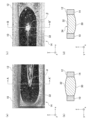
- FIGS. 1(a) to 1(d) are diagrams showing welded structures according to comparative objects of this embodiment. It is a sectional view showing the structure of the metallic member concerning a present Example.
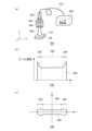
- 3(a)-(c) are diagrams showing the configuration of the welding apparatus according to the present embodiment.
- 4(a)-(c) are diagrams showing injection of assist gas in the welding apparatus of FIG. 3(a).
- 5(a)-(c) are diagrams showing a welded structure according to this embodiment.
- 6(a)-(d) are other diagrams showing the welded structure according to this embodiment.
- 7(a) and 7(b) are diagrams showing a welded structure according to a modification.
- Figs. 1(a)-(d) show a welded structure for comparison with this embodiment.
- line-shaped laser welding is performed on a plate-shaped metal member 10 having a first surface 12 and a second surface 14 facing in opposite directions.
- a Cartesian coordinate system is shown including the x, y and z axes as shown in FIGS. 1(a)-(d).
- the x-axis and the y-axis are orthogonal within the first surface 12 of the metal member 10, and when the x-axis direction is referred to as the "first direction", the y-axis direction is referred to as the "second direction”.
- the z-axis faces the thickness direction of the metal member 10 .
- the positive side of the z-axis is called “upper”
- the negative side of the z-axis is called “lower”.
- the first surface 12 is irradiated with the laser.
- welding between metals requires a high power density. is done.
- FIG. 1(a) is a plan view of the vicinity of the starting point ⁇ in the welded structure to be compared when viewed from the first surface 12 side
- FIG. 1(b) is the AA' line of FIG. 1(a). It is a cross-sectional view in.
- the start point ⁇ is a point at which scanning of the laser irradiation of the spot is started.
- a solidified portion 30 is formed by laser irradiation on the first surface 12 .
- the solidified portion 30 is a portion of the metal member 10 melted by the laser irradiation and solidified after the laser irradiation ends.
- the solidified portion 30 has a bead 32 projecting from the first surface 12 .
- FIG. 1(c) is a plan view of the vicinity of the end point ⁇ in the welded structure to be compared when viewed from the first surface 12 side, and FIG. 1(d) is the BB' line of FIG. 1(c). It is a cross-sectional view in.
- the end point ⁇ is a point at which scanning of the laser irradiation of the spot ends.
- a solidified portion 30 is formed in the same manner as in FIGS. 1(a)-(b). However, a dimple 34 is present in the bead 32 .
- the heat input at the starting point ⁇ and the ending point ⁇ it is difficult to control the heat input at the starting point ⁇ and the ending point ⁇ .
- the starting point ⁇ it is possible to form the protrusion of the bead 32 to some extent by scanning at a low speed or the like.
- a depression 34 is formed by any means.
- the bead 32 having a uniform shape is not formed over the long side direction, for example, the x direction, and the welding quality is degraded.
- FIG. 2 is a cross-sectional view showing the structure of the metal member 100.
- Metal member 100 includes a first member 110 and a second member 120 .
- the first member 110 and the second member 120 may be made of the same metal or different metals.
- the first member 110 has a first side 112 and a second side 114 facing in opposite directions. For example, the first surface 112 faces upward and the second surface 114 faces downward.
- the second member 120 has a third side 122 and a fourth side 124 facing in opposite directions.
- the third surface 122 faces upward and the fourth surface 124 faces downward.
- the first member 110 and the second member 120 are overlapped so that the second surface 114 of the first member 110 is aligned with the third surface 122 of the second member 120 .
- a welding device 300 shown in FIG. 3A includes a laser oscillator 200, an optical fiber 210, a collimator 220, a beam homogenizer 230 and a condenser lens 240.
- a laser oscillator 200 emits a laser beam such as a solid-state laser. The laser beam is applied to collimator 220 via optical fiber 210 . Collimator 220 collimates the laser beam from optical fiber 210 .
- the beam homogenizer 230 splits the laser beam incident from the collimator 220 into a plurality of beams.
- the traveling direction of the incident laser beam is, for example, the negative direction of the z-axis.
- the beam homogenizer 230 rotates and arranges each of the split laser beams by a predetermined angle in the xy plane perpendicular to the negative direction of the z-axis.
- the split laser beams have different values in the x-direction and in the direction. That is, the split laser beams are rearranged so as to have a different arrangement from the incident laser beams.
- the beam homogenizer 230 shapes a line-shaped laser beam 250 from the reordered laser beam. For example, the line-shaped laser beam 250 is longer along the x-axis than along the y-axis.
- FIG. 3(b) shows the beam intensity of the line-shaped laser beam 250 formed by the beam homogenizer 230.
- the horizontal axis indicates the x-axis along which the line-shaped laser beam 250 extends, and the vertical axis indicates the beam intensity.
- Both ends of the line-shaped laser beam 250 in the x-axis direction are indicated as a first end 252 and a second end 254 .
- a central portion 256 is a portion of the line-shaped laser beam 250 sandwiched between the first end portion 252 and the second end portion 254 .
- the beam intensity at first end 252 and second end 254 is made higher than the beam intensity at central portion 256 .
- the heating amount at the first end portion 252 and the second end portion 254 is increased more than at the central portion 256. It's for. The greater the heat that escapes during welding, the less likely it is to form a bead.
- FIG. 3(c) shows the shape of the line-shaped laser beam 250 formed by the beam homogenizer 230.
- FIG. This shows the xy plane as viewed from the positive side of the z-axis.
- 3(c) also shows a first end portion 252, a second end portion 254, and a central portion 256 as in FIG. 3(b).
- the beam width in the y-axis direction at the first end 252 and the second end 254 is made wider than the beam width in the y-axis direction at the central portion 256 .
- the beam homogenizer 230 irradiates the first surface 112 of the first member 110 with a line-shaped laser beam 250 through the condenser lens 240 .
- FIG. Welding device 300 injects an assist gas toward a portion irradiated with laser beam 250 on first surface 112 in order to prevent oxidation of metal and promote welding during laser welding.
- the assist gas is nitrogen gas, for example. That is, when the first surface 112 of the first member 110 is irradiated with the line-shaped laser beam 250 , the assist gas is injected onto the first surface 112 .
- FIG. 4(a) is an assist gas injection structure to be compared.
- FIG. 4(a) is shown with the y-axis oriented horizontally.
- a nozzle 260 is arranged to face the first surface 112 , and the nozzle 260 injects an assist gas 262 onto the first surface 112 .
- the assist gas 262 is reflected by the first surface 112 and reaches the portion irradiated with the laser beam 250 while entraining air around the first surface 112 .
- air is involved in the assist gas 262 and the metal is oxidized.
- FIG. 4(b) shows the injection structure of the assist gas according to this embodiment.
- FIG. 4(b) is shown with the y-axis oriented horizontally as in FIG. 4(a).
- a nozzle 270 is arranged along the first surface 112 , and the nozzle 270 injects an assist gas 272 along the first surface 112 .
- the assist gas 272 reaches the portion irradiated with the laser beam 250 along the first surface 112 . In this case, the amount of air involved is smaller than in FIG. 4(a), so oxidation of the metal is suppressed.
- FIG. 4(c) shows the first surface 112 viewed from the positive side of the z-axis.
- a portion of the first surface 112 irradiated with the first end portion 252 and the second end portion 254 of the line-shaped laser beam 250 is indicated as a first portion 274
- the central portion 256 of the line-shaped laser beam 250 is indicated as a first portion 274
- the irradiated portion is indicated as second portion 276 .
- the nozzle 270 extends in the x-axis direction along with the line-shaped laser beam 250 and jets an assist gas 272 .
- the flow velocity of the assist gas 272 with respect to the first portion 274 is made smaller than the flow velocity of the assist gas 272 with respect to the second portion 276 .
- first end 252 and the second end 254 are more likely to dissipate heat during welding than the central portion 256, and the assist gas 272 has a heat dissipation effect. This is for reducing the amount of heat radiation at the two end portions 254 .
- FIG. 5(a)-(c) show a welded structure.
- FIG. 5(a) is a structure viewed from the same direction as FIG. 2
- FIG. 5(b) is a cross-sectional view taken along line CC' of FIG. 5(a)
- FIG. 5(c). is the structure when viewed from the positive side of the z-axis.
- First member 110 and second member 120 of metal member 100 are shown in the same manner as in FIG.
- a solidified portion 130 is formed by irradiating the first surface 112 with a line-shaped laser beam 250 .
- the solidified portion 130 is a portion where the first member 110 and the second member 120 melted by laser irradiation are solidified after the laser irradiation ends.
- the solidified portion 130 can also be said to be a melted portion from the first surface 112 of the first member 110 through the second surface 114 to the second member 120 .
- Solidified portion 130 joins first member 110 and second member 120 .
- the solidified portion 130 has a bead 132 that protrudes from the first surface 112 and is longer in the x-axis direction than in the y-axis direction.
- the length of the bead 132 in the x-axis direction is ten times or more the length of the bead 132 in the y-axis direction.
- the bead 132 does not have a depression. It can also be said that the central portion of the bead 132 in cross-section in the y-axis direction swells over the entire x-axis direction. In particular, both ends of the line-shaped bead 132 are swollen.
- FIG. 6(a)-(d) show a welded structure and are shown for comparison with Figures 1(a)-(d).
- FIG. 6(a) is a plan view of the vicinity of the negative end of the x-axis in the welded structure viewed from the first surface 112 side, and
- FIG. 6(b) is DD' of FIG. 6(a).
- 1 is a cross-sectional view on line;
- FIG. A bead 132 in the solidified portion 130 protrudes from the first surface 112 .
- FIG. 6(c) is a plan view of the vicinity of the positive end of the x-axis in the welded structure viewed from the first surface 112 side, and
- FIG. 6(d) is EE' of FIG. 6(c) 1 is a cross-sectional view on line;
- FIG. The bead 132 in the solidified portion 130 protrudes from the first surface 112, and the bead 132 has no recess.
- a battery has, for example, a structure in which an electrode group is housed in an outer can together with an electrolytic solution.
- the electrode group has a wound structure in which strip-shaped electrode plates and strip-shaped separators are laminated and then spirally wound.
- a collector plate is arranged on one end side of the electrode plate of the electrode group. The electrode plate and current collector plate are joined by laser welding.
- FIGS. 7(a)-(b) show a welded structure according to a modified example.
- This corresponds to a welded structure applied to the end face current collection of the negative electrode of a battery.
- the current collector plate 140 has a first side 142 and a second side 144 facing in opposite directions.
- the current collecting plate 140 is made of nickel-plated iron, for example.
- the current collector plate 140, the first surface 142, and the second surface 144 correspond to the first member 110, the first surface 112, and the second surface 114 described above.
- the electrode plate 150 is made of copper foil.
- the electrode plate 150 corresponds to the second member 120 .
- the collector plate 140 and the electrode plate 150 are joined by the solidified portion 130 .
- the welded structure may be applied to the end face current collection of the positive electrode of the battery.
- the current collector plate 140 is made of, for example, an aluminum plate, and the electrode plate 150 is made of aluminum foil.
- the beam intensity at both ends of the line-shaped laser beam 250 is made higher than the beam intensity at the central portion 256. Therefore, even if heat escapes more easily at both ends than at the central portion 256, the central portion The welding quality in the long side direction can be made close to 256 and both end portions. In addition, since the weld quality in the longitudinal direction is close between the center portion 256 and both end portions, the weld quality in line-shaped welding can be improved. In addition, since the beam width at both ends is made wider than the beam width at the central portion 256, even if heat escapes more easily at both ends than at the central portion 256, the welding quality in the long side direction between the central portion 256 and both ends can be improved. I can do it soon.
- the flow velocity of the assist gas 272 at both end portions is made smaller than the flow velocity of the assist gas 272 at the central portion, the temperature drop during welding due to the assist gas 272 can be suppressed. In addition, since the temperature drop during welding due to the assist gas 272 is suppressed, the welding quality in line-shaped welding can be improved. Also, since the assist gas 272 is injected along the first surface 112, the amount of air involved in the assist gas 272 can be suppressed. Also, since the amount of air entrained in the assist gas 272 is suppressed, oxidation of the metal member 100 can be suppressed.
- the welding quality in the long side direction can be made close to the center and both ends.
- the welding quality in the long side direction is close to the central portion and the both end portions, stable welding can be realized.
- high-quality welding can be stably supplied at low cost.
- high-speed welding can be realized with high reliability and high operation rate.
- high-speed welding is realized with high reliability and high operating rate, high-quality and low-cost batteries can be provided.
- the length of the bead 132 in the long side direction is 10 times or more as long as the length in the short side direction, the bead 132 having a line shape can be realized.
- the assist gas (272) is injected along the first surface (112), The welding method according to item 4.
- the step of injecting an assist gas (272) to the first surface (112) of the first member (110) when irradiating the first surface (112) of the first member (110) with the line-shaped laser beam (250) is further performed.
- the assist gas (272) is injected along the first surface (112), The welding method according to any one of Items 1 to 3.
- a metal member (100) comprising a first member (110) having a first side (112) and a second side (114) facing in opposite directions and having a second side (114) overlaid with a second side (120). is a welded structure of a solidified portion (130) melted from the first surface (112) of the first member (110) through the second surface (114) to the second member (120);
- the solidified portion (130) has a bead (132) protruding from the first surface (112), When defining a first direction and a second direction that intersect in the first surface (112), the bead (132) has a line shape that is longer along the first direction than the second direction. , said bead (132) has no dimples;
- the length of the bead (132) in the first direction is 10 times or more the length of the bead (132) in the second direction, A welded structure of the metal member (100) according to item 7.
- the first member (110) is a current collector plate (140) of a battery, wherein said second member (120) is an electrode plate (150) of said battery; Welded structure of the metal member (100) according to item 7 or 8.
- the current collecting plate (140) is made of nickel-plated iron,
- the electrode plate (150) is formed of copper foil, A welded structure of the metal member (100) according to item 9.
- the welding quality in line-shaped welding can be improved.
- Metal member 12 First surface 14 Second surface 30 Solidified part 32 Bead 34 Recess 100 Metal member 110 First member 112 First surface 114 Second surface 120 Second member 122 Second 3 surface, 124 fourth surface, 130 solidification part, 132 bead, 140 current collector, 142 first surface, 144 second surface, 150 electrode plate, 200 laser oscillator, 210 optical fiber, 220 collimator, 230 beam homogenizer, 240 Condensing lens 250 Laser beam 252 First end 254 Second end 256 Central part 260 Nozzle 262 Assist gas 270 Nozzle 272 Assist gas 274 First part 276 Second part 300 Welding Device, ⁇ start point, ⁇ end point.
Landscapes
- Physics & Mathematics (AREA)
- Optics & Photonics (AREA)
- Engineering & Computer Science (AREA)
- Plasma & Fusion (AREA)
- Mechanical Engineering (AREA)
- Chemical & Material Sciences (AREA)
- Chemical Kinetics & Catalysis (AREA)
- Electrochemistry (AREA)
- General Chemical & Material Sciences (AREA)
- Laser Beam Processing (AREA)
Abstract
Provided is a metal member 100 in which a second member 120 is stacked on a second surface 114 of a first member 110 that includes a first surface 112 and the second surface 114 which are facing in opposite directions. A solidified section 130 is a melted portion which runs from the first surface 112 of the first member 110 to the second member 120, with the second surface 114 interposed therebetween. The solidified section 130 has a bead 132 that protrudes from the first surface 112. In a case where a first direction and a second direction that intersect within the first surface 112 are defined, the bead 132 has a line shape that is longer along the first direction than the second direction, and the bead 132 has no depressions.
Description
本開示は、溶接方法および金属部材の溶接構造に関する。
The present disclosure relates to a welding method and a welded structure of metal members.
レーザアニール、特に液晶ディスプレイのa-Si薄膜のp-Si化のために、ライン形状のレーザビームが使用される。このライン形状のレーザビームは、入射したレーザビームを所定数に分割し、入射ビームとは異なる配列に並べ替え、均一な強度にすることによって成型される(例えば、特許文献1参照)。
A line-shaped laser beam is used for laser annealing, especially for p-Si conversion of a-Si thin films of liquid crystal displays. This line-shaped laser beam is shaped by dividing an incident laser beam into a predetermined number, rearranging them into an array different from that of the incident beam, and making the intensity uniform (see, for example, Patent Document 1).
ライン形状のレーザビームでのレーザ加工は従来行われているが、一般的に、板材の金属の溶接に、ライン形状のレーザビームは使用されていない。その理由の1つ目は、入熱量が違うからである。a-Siの再溶融にライン形状のレーザビームを使用する場合、Siの融点は1430℃と高いが、加熱される深さが表面の数μm程度と小さいので、μsオーダのパルスレーザでも加熱でき、照射時間もμから数10μsと短い。一方、数100μm以上の金属溶接では、数10ms以上の加熱時間が必要となり、μsオーダ以下のパルスレーザでは溶接できない。また、理由の2つ目は、金属の溶接で短辺方向を短くし過ぎると、接合幅が小さ過ぎて接合強度が得られないからである。そのためビード幅として、数100μm以上必要となる。これにより、ライン形状のレーザビームの両端での熱の逃げが大きくなり、中央部と両端部とで溶接品質が異なる。
Although laser processing with a line-shaped laser beam has been conventionally performed, line-shaped laser beams are generally not used for welding plate metals. The first reason is that the amount of heat input is different. When a line-shaped laser beam is used to remelt a-Si, the melting point of Si is as high as 1430°C, but since the depth of heating is as small as several μm from the surface, even a μs-order pulse laser can heat it. , the irradiation time is as short as μ to several tens of μs. On the other hand, welding of a metal with a thickness of several 100 μm or more requires a heating time of several 10 ms or more, and cannot be welded with a pulse laser of μs order or less. The second reason is that if the width of the short side of the metal is too short, the width of the joint will be too small and the strength of the joint will not be obtained. Therefore, a bead width of several 100 μm or more is required. As a result, heat escapes at both ends of the line-shaped laser beam, and the welding quality differs between the central portion and both ends.
本開示はこうした状況に鑑みてなされたものであり、その目的の1つは、ライン形状の溶接における溶接品質を向上する技術を提供することにある。
The present disclosure has been made in view of this situation, and one of its purposes is to provide a technique for improving welding quality in line-shaped welding.
上記課題を解決するために、本開示のある態様の溶接方法は、反対方向を向いた第1面と第2面とを有する第1部材の第2面に第2部材を重ねるステップと、第1部材の第1面にライン形状のレーザビームを照射するステップと、ライン形状のレーザビームの照射によって形成された凝固部が第1部材と第2部材とを接合するステップとを備える。第1面内において交差する第1方向と第2方向を規定する場合に、ライン形状のレーザビームは、第2方向よりも第1方向に沿って長く、ライン形状のレーザビームにおける第1方向の両端部分である第1端部と第2端部のビーム強度は、ライン形状のレーザビームにおいて第1端部と第2端部とに挟まれた中央部のビーム強度よりも高い。
In order to solve the above problems, a welding method according to one aspect of the present disclosure includes the steps of: overlapping a second member on a second surface of a first member having a first surface and a second surface facing in opposite directions; A step of irradiating a first surface of one member with a line-shaped laser beam; and a step of joining the first member and the second member by a solidified portion formed by the irradiation of the line-shaped laser beam. When defining a first direction and a second direction that intersect in the first plane, the line-shaped laser beam is longer along the first direction than the second direction, and the length of the line-shaped laser beam in the first direction is longer than the second direction. The beam intensity at the first end and the second end, which are both end portions, is higher than the beam intensity at the central portion sandwiched between the first end and the second end in the line-shaped laser beam.
本開示の別の態様は、溶接方法である。この方法は、反対方向を向いた第1面と第2面とを有する第1部材の第2面に第2部材を重ねるステップと、第1部材の第1面にライン形状のレーザビームを照射するステップと、ライン形状のレーザビームの照射によって形成された凝固部が第1部材と第2部材とを接合するステップとを備える。第1面内において交差する第1方向と第2方向を規定する場合に、ライン形状のレーザビームは、第2方向よりも第1方向に沿って長く、ライン形状のレーザビームにおける第1方向の両端部分が第1端部と第2端部とされ、ライン形状のレーザビームにおける第1端部と第2端部との間が中央部とされる場合に、第1端部と第2端部における第2方向のビーム幅は、中央部における第2方向のビーム幅よりも広い。
Another aspect of the present disclosure is a welding method. This method includes the steps of: stacking a second member on a second surface of a first member having first and second surfaces facing in opposite directions; and irradiating the first surface of the first member with a line-shaped laser beam. and a step of joining the first member and the second member by the solidified portion formed by the line-shaped laser beam irradiation. When defining a first direction and a second direction that intersect in the first plane, the line-shaped laser beam is longer along the first direction than the second direction, and the length of the line-shaped laser beam in the first direction is longer than the second direction. When both end portions are the first end and the second end, and the center portion is between the first end and the second end of the line-shaped laser beam, the first end and the second end The beam width in the second direction at the portion is wider than the beam width in the second direction at the central portion.
本開示のさらに別の態様は、金属部材の溶接構造である。この溶接構造は、反対方向を向いた第1面と第2面とを有する第1部材の第2面に第2部材を重ねた金属部材の溶接構造であり、第1部材の第1面から第2面を介して第2部材にわたって溶融した凝固部を備える。凝固部は、第1面から突出するビードを有する。第1面内において交差する第1方向と第2方向を規定する場合に、ビードは、第2方向よりも第1方向に沿って長いライン形状を有する。ビードは窪みを有さない。
Yet another aspect of the present disclosure is a welded structure of metal members. The welded structure is a welded structure of metal members in which a second member is superimposed on a second surface of a first member having a first surface and a second surface facing in opposite directions, and from the first surface of the first member A molten solidified portion is provided across the second member through the second surface. The solidified portion has a bead protruding from the first surface. When defining a first direction and a second direction that intersect in the first plane, the bead has a line shape that is longer along the first direction than the second direction. The bead has no dimples.
以上の構成要素の任意の組合せ、本開示の表現を方法、装置、システムなどの間で変換したものもまた、本開示の態様として有効である。
Any combination of the above components, and expressions of the present disclosure converted between methods, devices, systems, etc. are also effective as aspects of the present disclosure.
本開示によれば、ライン形状の溶接における溶接品質を向上できる。
According to the present disclosure, the welding quality in line-shaped welding can be improved.
以下、本開示を好適な実施例をもとに図面を参照しながら説明する。実施例は、本開示を限定するものではなく例示であって、実施例に記述されるすべての特徴やその組合せは、必ずしも本開示の本質的なものであるとは限らない。各図面に示される同一または同等の構成要素、部材、処理には、同一の符号を付するものとし、適宜重複した説明は省略する。また、各図に示す各部の縮尺や形状は、説明を容易にするために便宜的に設定されており、特に言及がない限り限定的に解釈されるものではない。また、本明細書または請求項中に「第1」、「第2」等の用語が用いられる場合には、特に言及がない限りこの用語はいかなる順序や重要度を表すものでもなく、ある構成と他の構成とを区別するためのものである。また、各図面において実施例を説明する上で重要ではない部材の一部は省略して表示する。
The present disclosure will be described below based on preferred embodiments with reference to the drawings. The examples are illustrative rather than limiting of the present disclosure, and not all features or combinations thereof described in the examples are necessarily essential to the present disclosure. The same or equivalent constituent elements, members, and processes shown in each drawing are denoted by the same reference numerals, and duplication of description will be omitted as appropriate. In addition, the scale and shape of each part shown in each drawing are set for convenience in order to facilitate the explanation, and should not be construed as limiting unless otherwise mentioned. In addition, when terms such as "first" and "second" are used in this specification or claims, unless otherwise specified, these terms do not represent any order or degree of importance. and other configurations. Also, in each drawing, some of the members that are not important for explaining the embodiments are omitted.
図1(a)-(d)は、本実施例の比較対象に係る溶接構造を示す。比較対象では、反対を向いた第1面12と第2面14とを有する板形状の金属部材10に対してライン状のレーザ溶接がなされる。図1(a)-(d)に示されるようにx軸、y軸、z軸を含む直交座標系が示される。x軸とy軸は、金属部材10の第1面12内において直交し、x軸の方向を「第1方向」と呼ぶ場合にy軸の方向は「第2方向」と呼ばれる。また、z軸は、金属部材10の厚さ方向を向く。z軸の正方向側を「上側」と呼ぶ場合、z軸の負方向側は「下側」と呼ばれる。比較対象では、第1面12に対してレーザ照射がなされる。一般的に、板形状の金属部材10が溶接対象である場合、金属同士の溶接には高パワー密度が必要であるので、レーザビームを絞ったスポットをスキャナ等で走査することによってライン状の溶接がなされる。
Figs. 1(a)-(d) show a welded structure for comparison with this embodiment. For comparison, line-shaped laser welding is performed on a plate-shaped metal member 10 having a first surface 12 and a second surface 14 facing in opposite directions. A Cartesian coordinate system is shown including the x, y and z axes as shown in FIGS. 1(a)-(d). The x-axis and the y-axis are orthogonal within the first surface 12 of the metal member 10, and when the x-axis direction is referred to as the "first direction", the y-axis direction is referred to as the "second direction". Also, the z-axis faces the thickness direction of the metal member 10 . If the positive side of the z-axis is called "upper", the negative side of the z-axis is called "lower". For comparison, the first surface 12 is irradiated with the laser. In general, when a plate-shaped metal member 10 is to be welded, welding between metals requires a high power density. is done.
図1(a)は、比較対象の溶接構造における始点α近傍を第1面12側から見た場合の平面図であり、図1(b)は、図1(a)のA-A’線における断面図である。始点αとは、スポットのレーザ照射の走査が開始される点である。第1面12に対するレーザ照射により凝固部30が形成される。凝固部30は、レーザ照射によって溶融した金属部材10が、レーザ照射の終了後に凝固した部分である。凝固部30は、第1面12から突出するビード32を有する。図1(c)は、比較対象の溶接構造における終点β近傍を第1面12側から見た場合の平面図であり、図1(d)は、図1(c)のB-B’線における断面図である。終点βとは、スポットのレーザ照射の走査が終了される点である。図1(c)-(d)では、図1(a)-(b)と同様に凝固部30が形成される。しかしながら、ビード32に窪み34が存在する。
FIG. 1(a) is a plan view of the vicinity of the starting point α in the welded structure to be compared when viewed from the first surface 12 side, and FIG. 1(b) is the AA' line of FIG. 1(a). It is a cross-sectional view in. The start point α is a point at which scanning of the laser irradiation of the spot is started. A solidified portion 30 is formed by laser irradiation on the first surface 12 . The solidified portion 30 is a portion of the metal member 10 melted by the laser irradiation and solidified after the laser irradiation ends. The solidified portion 30 has a bead 32 projecting from the first surface 12 . FIG. 1(c) is a plan view of the vicinity of the end point β in the welded structure to be compared when viewed from the first surface 12 side, and FIG. 1(d) is the BB' line of FIG. 1(c). It is a cross-sectional view in. The end point β is a point at which scanning of the laser irradiation of the spot ends. In FIGS. 1(c)-(d), a solidified portion 30 is formed in the same manner as in FIGS. 1(a)-(b). However, a dimple 34 is present in the bead 32 .
スポットを走査する場合、始点αおよび終点βでの熱の入りを制御することが困難である。始点αでは、低速での走査などによってある程度のビード32の突出を形成することが可能である。一方、終点βではいかなる工夫によっても窪み34が形成されてしまう。その結果、長辺方向、例えばx方向にわたって均一な形状のビード32が形成されず、溶接品質が低下される。
When scanning a spot, it is difficult to control the heat input at the starting point α and the ending point β. At the starting point α, it is possible to form the protrusion of the bead 32 to some extent by scanning at a low speed or the like. On the other hand, at the end point β, a depression 34 is formed by any means. As a result, the bead 32 having a uniform shape is not formed over the long side direction, for example, the x direction, and the welding quality is degraded.
以下では、ライン状のレーザ溶接における溶接品質を向上するための溶接方法、溶接構造を(1)積層工程、(2)レーザ照射工程、(3)凝固工程の順に説明する。また、x軸、y軸、z軸を含む直交座標系はこれまでと同様に定義される。
(1)積層工程
図2は、金属部材100の構造を示す断面図である。金属部材100は、第1部材110と第2部材120を含む。第1部材110と第2部材120は同一の金属であってもよく、異なった金属であってもよい。第1部材110は、反対方向を向いた第1面112と第2面114とを有する。例えば、第1面112は上側を向き、第2面114は下側を向く。第2部材120は、反対方向を向いた第3面122と第4面124とを有する。例えば、第3面122は上側を向き、第4面124は下側を向く。第1部材110の第2面114に第2部材120の第3面122を合わせるように、第1部材110と第2部材120とが重ねられる。 Below, a welding method and a welded structure for improving the welding quality in line-shaped laser welding will be described in the order of (1) lamination step, (2) laser irradiation step, and (3) solidification step. Also, a Cartesian coordinate system including x-, y-, and z-axes is defined as before.
(1) Stacking Step FIG. 2 is a cross-sectional view showing the structure of themetal member 100. As shown in FIG. Metal member 100 includes a first member 110 and a second member 120 . The first member 110 and the second member 120 may be made of the same metal or different metals. The first member 110 has a first side 112 and a second side 114 facing in opposite directions. For example, the first surface 112 faces upward and the second surface 114 faces downward. The second member 120 has a third side 122 and a fourth side 124 facing in opposite directions. For example, the third surface 122 faces upward and the fourth surface 124 faces downward. The first member 110 and the second member 120 are overlapped so that the second surface 114 of the first member 110 is aligned with the third surface 122 of the second member 120 .
(1)積層工程
図2は、金属部材100の構造を示す断面図である。金属部材100は、第1部材110と第2部材120を含む。第1部材110と第2部材120は同一の金属であってもよく、異なった金属であってもよい。第1部材110は、反対方向を向いた第1面112と第2面114とを有する。例えば、第1面112は上側を向き、第2面114は下側を向く。第2部材120は、反対方向を向いた第3面122と第4面124とを有する。例えば、第3面122は上側を向き、第4面124は下側を向く。第1部材110の第2面114に第2部材120の第3面122を合わせるように、第1部材110と第2部材120とが重ねられる。 Below, a welding method and a welded structure for improving the welding quality in line-shaped laser welding will be described in the order of (1) lamination step, (2) laser irradiation step, and (3) solidification step. Also, a Cartesian coordinate system including x-, y-, and z-axes is defined as before.
(1) Stacking Step FIG. 2 is a cross-sectional view showing the structure of the
(2)レーザ照射工程
図3(a)-(c)は、溶接装置300の構成を示す。図3(a)に示される溶接装置300は、レーザ発振器200、光ファイバ210、コリメータ220、ビームホモジナイザ230、集光レンズ240を含む。レーザ発振器200は、固体レーザ等のレーザビームを照射する。レーザビームは、光ファイバ210を介してコリメータ220に照射される。コリメータ220は、光ファイバ210からのレーザビームを平行にする。 (2) Laser Irradiation Process FIGS. Awelding device 300 shown in FIG. 3A includes a laser oscillator 200, an optical fiber 210, a collimator 220, a beam homogenizer 230 and a condenser lens 240. A laser oscillator 200 emits a laser beam such as a solid-state laser. The laser beam is applied to collimator 220 via optical fiber 210 . Collimator 220 collimates the laser beam from optical fiber 210 .
図3(a)-(c)は、溶接装置300の構成を示す。図3(a)に示される溶接装置300は、レーザ発振器200、光ファイバ210、コリメータ220、ビームホモジナイザ230、集光レンズ240を含む。レーザ発振器200は、固体レーザ等のレーザビームを照射する。レーザビームは、光ファイバ210を介してコリメータ220に照射される。コリメータ220は、光ファイバ210からのレーザビームを平行にする。 (2) Laser Irradiation Process FIGS. A
ビームホモジナイザ230は、コリメータ220から入射したレーザビームを複数に分割する。入射したレーザビームの進行方向は、例えばz軸の負方向である。ビームホモジナイザ230は、分割したレーザビームのそれぞれに対して、z軸の負方向に直交したx-y平面内において所定角度まで回転させて配列する。その結果、分割したレーザビームのそれぞれにおいて、x方向の値と方向の値が互いに異なる。つまり、分割したレーザビームは、入射したレーザビームとは異なる配列になるように並べ替えられる。さらに、ビームホモジナイザ230は、並び替えられたレーザビームからライン形状のレーザビーム250を成形する。例えば、ライン形状のレーザビーム250は、y軸の方向よりもx軸の方向に沿って長くされる。
The beam homogenizer 230 splits the laser beam incident from the collimator 220 into a plurality of beams. The traveling direction of the incident laser beam is, for example, the negative direction of the z-axis. The beam homogenizer 230 rotates and arranges each of the split laser beams by a predetermined angle in the xy plane perpendicular to the negative direction of the z-axis. As a result, the split laser beams have different values in the x-direction and in the direction. That is, the split laser beams are rearranged so as to have a different arrangement from the incident laser beams. Further, the beam homogenizer 230 shapes a line-shaped laser beam 250 from the reordered laser beam. For example, the line-shaped laser beam 250 is longer along the x-axis than along the y-axis.
図3(b)は、ビームホモジナイザ230において成形されるライン形状のレーザビーム250のビーム強度を示す。横軸は、ライン形状のレーザビーム250が延びるx軸を示し、縦軸は、ビーム強度を示す。ライン形状のレーザビーム250におけるx軸方向の両端部分は、第1端部252、第2端部254と示される。また、ライン形状のレーザビーム250において第1端部252と第2端部254とに挟まれた部分は中央部256と示される。ビームホモジナイザ230において、第1端部252と第2端部254のビーム強度は、中央部256のビーム強度よりも高くされる。これは、中央部256よりも第1端部252と第2端部254において溶接時に熱が逃げやすいので、中央部256よりも第1端部252と第2端部254における加熱量を大きくするためである。溶接時に逃げる熱が大きくなると、ビードが形成されにくくなる。
FIG. 3(b) shows the beam intensity of the line-shaped laser beam 250 formed by the beam homogenizer 230. FIG. The horizontal axis indicates the x-axis along which the line-shaped laser beam 250 extends, and the vertical axis indicates the beam intensity. Both ends of the line-shaped laser beam 250 in the x-axis direction are indicated as a first end 252 and a second end 254 . A central portion 256 is a portion of the line-shaped laser beam 250 sandwiched between the first end portion 252 and the second end portion 254 . In beam homogenizer 230 , the beam intensity at first end 252 and second end 254 is made higher than the beam intensity at central portion 256 . Since heat escapes more easily at the first end portion 252 and the second end portion 254 than at the central portion 256 during welding, the heating amount at the first end portion 252 and the second end portion 254 is increased more than at the central portion 256. It's for. The greater the heat that escapes during welding, the less likely it is to form a bead.
図3(c)は、ビームホモジナイザ230において成形されるライン形状のレーザビーム250の形状を示す。これは、z軸の正方向側から見た場合のx-y平面を示す。図3(c)でも、図3(b)と同様に、第1端部252、第2端部254、中央部256が示される。ビームホモジナイザ230では、第1端部252と第2端部254におけるy軸方向のビーム幅が、中央部256におけるy軸方向のビーム幅よりも広くされる。これも、中央部256よりも第1端部252と第2端部254において溶接時に熱が逃げやすいので、中央部256よりも第1端部252と第2端部254における加熱量を大きくするためである。図3(a)に戻る。ビームホモジナイザ230は、集光レンズ240を介して、第1部材110の第1面112にライン形状のレーザビーム250を照射する。
FIG. 3(c) shows the shape of the line-shaped laser beam 250 formed by the beam homogenizer 230. FIG. This shows the xy plane as viewed from the positive side of the z-axis. 3(c) also shows a first end portion 252, a second end portion 254, and a central portion 256 as in FIG. 3(b). In the beam homogenizer 230 , the beam width in the y-axis direction at the first end 252 and the second end 254 is made wider than the beam width in the y-axis direction at the central portion 256 . Also, since heat is more likely to escape at the first end 252 and the second end 254 than at the central portion 256 during welding, the amount of heating at the first end 252 and the second end 254 is increased more than at the central portion 256. It's for. Return to FIG. 3(a). The beam homogenizer 230 irradiates the first surface 112 of the first member 110 with a line-shaped laser beam 250 through the condenser lens 240 .
図4(a)-(c)は、溶接装置300におけるアシストガスの噴射を示す。溶接装置300は、レーザ溶接の際における金属の酸化防止および溶接促進のために、第1面112におけるレーザビーム250の照射部分に向かってアシストガスが噴射される。アシストガスは例えば窒素ガスである。つまり、第1部材110の第1面112にライン形状のレーザビーム250を照射する際に、第1面112にアシストガスが噴射される。
4(a)-(c) show injection of the assist gas in the welding device 300. FIG. Welding device 300 injects an assist gas toward a portion irradiated with laser beam 250 on first surface 112 in order to prevent oxidation of metal and promote welding during laser welding. The assist gas is nitrogen gas, for example. That is, when the first surface 112 of the first member 110 is irradiated with the line-shaped laser beam 250 , the assist gas is injected onto the first surface 112 .
図4(a)は、比較対象となるアシストガスの噴射構造である。図4(a)は、y軸が横方向になるように示される。第1面112に向かうようにノズル260が配置され、ノズル260は、第1面112に対してアシストガス262を噴射する。アシストガス262は、第1面112において反射して、第1面112の周囲の空気を巻き込みながら、レーザビーム250が照射される部分に到達する。このような構造の場合、アシストガス262に空気が巻き込まれることによって、金属が酸化されてしまう。
FIG. 4(a) is an assist gas injection structure to be compared. FIG. 4(a) is shown with the y-axis oriented horizontally. A nozzle 260 is arranged to face the first surface 112 , and the nozzle 260 injects an assist gas 262 onto the first surface 112 . The assist gas 262 is reflected by the first surface 112 and reaches the portion irradiated with the laser beam 250 while entraining air around the first surface 112 . In the case of such a structure, air is involved in the assist gas 262 and the metal is oxidized.
図4(b)は、本実施例に係るアシストガスの噴射構造である。図4(b)は、図4(a)と同様にy軸が横方向になるように示される。第1面112に沿うようにノズル270が配置され、ノズル270は、第1面112に沿ってアシストガス272を噴射する。アシストガス272は、第1面112に沿って、レーザビーム250が照射される部分に到達する。この場合、巻き込まれる空気の量が図4(a)よりも少なくなるので、金属の酸化が抑制される。
FIG. 4(b) shows the injection structure of the assist gas according to this embodiment. FIG. 4(b) is shown with the y-axis oriented horizontally as in FIG. 4(a). A nozzle 270 is arranged along the first surface 112 , and the nozzle 270 injects an assist gas 272 along the first surface 112 . The assist gas 272 reaches the portion irradiated with the laser beam 250 along the first surface 112 . In this case, the amount of air involved is smaller than in FIG. 4(a), so oxidation of the metal is suppressed.
図4(c)は、第1面112をz軸の正方向側から見た場合を示す。第1面112のうち、ライン形状のレーザビーム250における第1端部252と第2端部254が照射される部分が第1部分274と示され、ライン形状のレーザビーム250における中央部256が照射される部分が第2部分276と示される。ノズル270は、ライン形状のレーザビーム250にあわせてx軸方向に延びており、アシストガス272を噴射する。ここで、第1部分274に対するアシストガス272の流速は、第2部分276に対するアシストガス272の流速よりも小さくされる。これは、中央部256よりも第1端部252と第2端部254において溶接時に熱が逃げやく、かつアシストガス272に放熱効果があるので、中央部256よりも第1端部252と第2端部254における放熱量を小さくするためである。
FIG. 4(c) shows the first surface 112 viewed from the positive side of the z-axis. A portion of the first surface 112 irradiated with the first end portion 252 and the second end portion 254 of the line-shaped laser beam 250 is indicated as a first portion 274 , and the central portion 256 of the line-shaped laser beam 250 is indicated as a first portion 274 . The irradiated portion is indicated as second portion 276 . The nozzle 270 extends in the x-axis direction along with the line-shaped laser beam 250 and jets an assist gas 272 . Here, the flow velocity of the assist gas 272 with respect to the first portion 274 is made smaller than the flow velocity of the assist gas 272 with respect to the second portion 276 . This is because the first end 252 and the second end 254 are more likely to dissipate heat during welding than the central portion 256, and the assist gas 272 has a heat dissipation effect. This is for reducing the amount of heat radiation at the two end portions 254 .
(3)凝固工程
ライン形状のレーザビーム250の照射が終了すると、金属部材100は凝固工程となる。図5(a)-(c)は、溶接構造を示す。図5(a)は、図2と同じ方向から見た場合の構造であり、図5(b)は、図5(a)のC-C’線における断面図であり、図5(c)は、z軸の正方向側から見た場合の構造である。金属部材100における第1部材110と第2部材120は図2と同様に示されており、第1部材110の第2面114に第2部材120が重ねられる。第1面112に対してライン形状のレーザビーム250の照射がなされることによって凝固部130が形成される。凝固部130は、レーザ照射によって溶融した第1部材110と第2部材120が、レーザ照射の終了後に凝固した部分である。凝固部130は、第1部材110の第1面112から第2面114を介して第2部材120にわたって溶融した部分であるともいえる。凝固部130が第1部材110と第2部材120とを接合する。 (3) Solidification Step After the irradiation of the line-shapedlaser beam 250 is completed, the metal member 100 undergoes a solidification step. Figures 5(a)-(c) show a welded structure. FIG. 5(a) is a structure viewed from the same direction as FIG. 2, FIG. 5(b) is a cross-sectional view taken along line CC' of FIG. 5(a), and FIG. 5(c). is the structure when viewed from the positive side of the z-axis. First member 110 and second member 120 of metal member 100 are shown in the same manner as in FIG. A solidified portion 130 is formed by irradiating the first surface 112 with a line-shaped laser beam 250 . The solidified portion 130 is a portion where the first member 110 and the second member 120 melted by laser irradiation are solidified after the laser irradiation ends. The solidified portion 130 can also be said to be a melted portion from the first surface 112 of the first member 110 through the second surface 114 to the second member 120 . Solidified portion 130 joins first member 110 and second member 120 .
ライン形状のレーザビーム250の照射が終了すると、金属部材100は凝固工程となる。図5(a)-(c)は、溶接構造を示す。図5(a)は、図2と同じ方向から見た場合の構造であり、図5(b)は、図5(a)のC-C’線における断面図であり、図5(c)は、z軸の正方向側から見た場合の構造である。金属部材100における第1部材110と第2部材120は図2と同様に示されており、第1部材110の第2面114に第2部材120が重ねられる。第1面112に対してライン形状のレーザビーム250の照射がなされることによって凝固部130が形成される。凝固部130は、レーザ照射によって溶融した第1部材110と第2部材120が、レーザ照射の終了後に凝固した部分である。凝固部130は、第1部材110の第1面112から第2面114を介して第2部材120にわたって溶融した部分であるともいえる。凝固部130が第1部材110と第2部材120とを接合する。 (3) Solidification Step After the irradiation of the line-shaped
凝固部130は、第1面112から突出し、かつy軸方向よりもx軸方向に沿って長いビード132を有する。例えば、ビード132のx軸方向の長さは、ビード132のy軸方向の長さの10倍以上にされる。また、ビード132は窪みを有さない。これは、ビード132のy軸方向の断面形状における中央部分が、x軸方向全体にわたって膨らんでいるともいえる。特にライン形状のビード132の両端が膨らんでいる。
The solidified portion 130 has a bead 132 that protrudes from the first surface 112 and is longer in the x-axis direction than in the y-axis direction. For example, the length of the bead 132 in the x-axis direction is ten times or more the length of the bead 132 in the y-axis direction. Also, the bead 132 does not have a depression. It can also be said that the central portion of the bead 132 in cross-section in the y-axis direction swells over the entire x-axis direction. In particular, both ends of the line-shaped bead 132 are swollen.
図6(a)-(d)は、溶接構造を示しており、図1(a)-(d)と比較するために示される。図6(a)は、溶接構造におけるx軸の負側端近傍を第1面112側から見た場合の平面図であり、図6(b)は、図6(a)のD-D’線における断面図である。凝固部130におけるビード132は第1面112から突出する。図6(c)は、溶接構造におけるx軸の正側端近傍を第1面112側から見た場合の平面図であり、図6(d)は、図6(c)のE-E’線における断面図である。凝固部130におけるビード132は第1面112から突出しており、ビード132に窪みは存在しない。
Figures 6(a)-(d) show a welded structure and are shown for comparison with Figures 1(a)-(d). FIG. 6(a) is a plan view of the vicinity of the negative end of the x-axis in the welded structure viewed from the first surface 112 side, and FIG. 6(b) is DD' of FIG. 6(a). 1 is a cross-sectional view on line; FIG. A bead 132 in the solidified portion 130 protrudes from the first surface 112 . FIG. 6(c) is a plan view of the vicinity of the positive end of the x-axis in the welded structure viewed from the first surface 112 side, and FIG. 6(d) is EE' of FIG. 6(c) 1 is a cross-sectional view on line; FIG. The bead 132 in the solidified portion 130 protrudes from the first surface 112, and the bead 132 has no recess.
これまで説明した溶接方法と溶接構造は、例えばリチウムイオン二次電池等の電池において使用されてもよい。電池は、例えば、電極群が電解液とともに外装缶に収納された構造を有する。電極群は、帯状の電極板と帯状のセパレータが積層されてから、渦巻き状に巻回された巻回型構造を有する。電極群の電極板の一端側には集電板が配置される。電極板と集電板とは、レーザ溶接によって接合される。
The welding method and welding structure described so far may be used in batteries such as lithium-ion secondary batteries, for example. A battery has, for example, a structure in which an electrode group is housed in an outer can together with an electrolytic solution. The electrode group has a wound structure in which strip-shaped electrode plates and strip-shaped separators are laminated and then spirally wound. A collector plate is arranged on one end side of the electrode plate of the electrode group. The electrode plate and current collector plate are joined by laser welding.
図7(a)-(b)は、変形例に係る溶接構造を示す。これは、電池の負極の端面集電に適用される溶接構造に相当する。集電板140は、反対を向いた第1面142と第2面144とを有する。集電板140は、例えばニッケルめっきの鉄により形成される。集電板140、第1面142、第2面144は、これまでの第1部材110、第1面112、第2面114に対応する。電極板150は、銅箔により形成される。電極板150は第2部材120に対応する。集電板140と電極板150は凝固部130により接合される。溶接構造は、電池の正極の端面集電に適用されてもよい。その場合、集電板140は、例えばアルミニウム板により形成され、電極板150は、アルミニウム箔により形成される。
FIGS. 7(a)-(b) show a welded structure according to a modified example. This corresponds to a welded structure applied to the end face current collection of the negative electrode of a battery. The current collector plate 140 has a first side 142 and a second side 144 facing in opposite directions. The current collecting plate 140 is made of nickel-plated iron, for example. The current collector plate 140, the first surface 142, and the second surface 144 correspond to the first member 110, the first surface 112, and the second surface 114 described above. The electrode plate 150 is made of copper foil. The electrode plate 150 corresponds to the second member 120 . The collector plate 140 and the electrode plate 150 are joined by the solidified portion 130 . The welded structure may be applied to the end face current collection of the positive electrode of the battery. In that case, the current collector plate 140 is made of, for example, an aluminum plate, and the electrode plate 150 is made of aluminum foil.
本実施例によれば、ライン形状のレーザビーム250における両端部分におけるビーム強度を、中央部256のビーム強度よりも高くするので、中央部256よりも両端部分において熱が逃げやすくても、中央部256と両端部分とにおいて長辺方向の溶接品質を近くできる。また、中央部256と両端部分とにおいて長辺方向の溶接品質が近くなるので、ライン形状の溶接における溶接品質を向上できる。また、両端部分のビーム幅を中央部256のビーム幅よりも広くするので、中央部256よりも両端部分において熱が逃げやすくても、中央部256と両端部分とにおいて長辺方向の溶接品質を近くできる。
According to the present embodiment, the beam intensity at both ends of the line-shaped laser beam 250 is made higher than the beam intensity at the central portion 256. Therefore, even if heat escapes more easily at both ends than at the central portion 256, the central portion The welding quality in the long side direction can be made close to 256 and both end portions. In addition, since the weld quality in the longitudinal direction is close between the center portion 256 and both end portions, the weld quality in line-shaped welding can be improved. In addition, since the beam width at both ends is made wider than the beam width at the central portion 256, even if heat escapes more easily at both ends than at the central portion 256, the welding quality in the long side direction between the central portion 256 and both ends can be improved. I can do it soon.
両端部分におけるアシストガス272の流速を、中央部におけるアシストガス272の流速よりも小さくするので、アシストガス272による溶接の際の温度低下を抑制できる。また、アシストガス272による溶接の際の温度低下が抑制されるので、ライン形状の溶接における溶接品質を向上できる。また、アシストガス272は第1面112に沿って噴射されるので、アシストガス272における空気の巻き込み量を抑制できる。また、アシストガス272における空気の巻き込み量が抑制されるので、金属部材100の酸化を抑制できる。
Since the flow velocity of the assist gas 272 at both end portions is made smaller than the flow velocity of the assist gas 272 at the central portion, the temperature drop during welding due to the assist gas 272 can be suppressed. In addition, since the temperature drop during welding due to the assist gas 272 is suppressed, the welding quality in line-shaped welding can be improved. Also, since the assist gas 272 is injected along the first surface 112, the amount of air involved in the assist gas 272 can be suppressed. Also, since the amount of air entrained in the assist gas 272 is suppressed, oxidation of the metal member 100 can be suppressed.
また、ライン形状のビード132の両端において窪みが存在しないので、長辺方向の溶接品質を中央部と両端部分で近くできる。また、長辺方向の溶接品質が中央部と両端部分で近くなるので、安定した溶接を実現できる。また、安定した溶接が実現されるので、高品質の溶接を低コストで安定して供給できる。また、スキャナ等のレーザ装置の可動部がなく、高速溶接を高信頼性で高稼働率で実現できる。また、高速溶接が高信頼性で高稼働率で実現されるので、高品質で低コストな電池を提供できる。また、ビード132の長辺方向の長さは短辺方向の長さの10倍以上であるので、ライン形状のビード132を実現できる。
In addition, since there is no recess at both ends of the line-shaped bead 132, the welding quality in the long side direction can be made close to the center and both ends. In addition, since the welding quality in the long side direction is close to the central portion and the both end portions, stable welding can be realized. Moreover, since stable welding is realized, high-quality welding can be stably supplied at low cost. In addition, since there is no moving part of a laser device such as a scanner, high-speed welding can be realized with high reliability and high operation rate. In addition, since high-speed welding is realized with high reliability and high operating rate, high-quality and low-cost batteries can be provided. Further, since the length of the bead 132 in the long side direction is 10 times or more as long as the length in the short side direction, the bead 132 having a line shape can be realized.
以上、本開示の実施例について詳細に説明した。前述した実施例は、本開示を実施するにあたっての具体例を示したものにすぎない。実施例の内容は、本開示の技術的範囲を限定するものではなく、請求の範囲に規定された本開示の思想を逸脱しない範囲において、構成要素の変更、追加、削除等の多くの設計変更が可能である。設計変更が加えられた新たな実施例は、組み合わされる実施例および変形それぞれの効果をあわせもつ。前述の実施例では、このような設計変更が可能な内容に関して、「本実施例の」、「本実施例では」等の表記を付して強調しているが、そのような表記のない内容でも設計変更が許容される。以上の構成要素の任意の組合せも、本開示の態様として有効である。図面の断面に付したハッチングは、ハッチングを付した対象の材質を限定するものではない。
The embodiments of the present disclosure have been described in detail above. The above-described embodiments are merely examples of implementations of the present disclosure. The contents of the embodiments do not limit the technical scope of the present disclosure, and many design changes such as changes, additions, and deletions of constituent elements are possible within the scope that does not deviate from the spirit of the present disclosure defined in the claims. is possible. A new embodiment to which design changes have been added has the effects of the combined embodiment and modifications. In the above-described embodiment, the contents that allow such design changes are emphasized by adding notations such as "of this embodiment" and "in this embodiment", but contents without such notations. However, design changes are allowed. Any combination of the above components is also effective as an aspect of the present disclosure. The hatching attached to the cross section of the drawing does not limit the material of the hatched object.
上述した実施例に係る開示は、以下に記載する項目によって特定されてもよい。
[項目1]
反対方向を向いた第1面(112)と第2面(114)とを有する第1部材(110)の前記第2面(114)に第2部材(120)を重ねるステップと、
前記第1部材(110)の前記第1面(112)にライン形状のレーザビーム(250)を照射するステップと、
前記ライン形状のレーザビーム(250)の照射によって形成された凝固部(130)が前記第1部材(110)と前記第2部材(120)とを接合するステップとを備え、
前記第1面(112)内において交差する第1方向と第2方向を規定する場合に、前記ライン形状のレーザビーム(250)は、前記第2方向よりも前記第1方向に沿って長く、
前記ライン形状のレーザビーム(250)における前記第1方向の両端部分である第1端部(252)と第2端部(254)のビーム強度は、前記ライン形状のレーザビーム(250)において前記第1端部(252)と前記第2端部(254)とに挟まれた中央部(256)のビーム強度よりも高い、
溶接方法。 The example disclosures described above may be identified by the items listed below.
[Item 1]
overlaying a second member (120) on said second side (114) of said first member (110) having a first side (112) and a second side (114) facing in opposite directions;
irradiating the first surface (112) of the first member (110) with a line-shaped laser beam (250);
A solidified portion (130) formed by irradiation of the line-shaped laser beam (250) joins the first member (110) and the second member (120);
When defining a first direction and a second direction that intersect in the first surface (112), the line-shaped laser beam (250) is longer along the first direction than the second direction,
The beam intensity at the first end (252) and the second end (254), which are both end portions in the first direction, of the line-shaped laser beam (250) is greater than the beam intensity in a central portion (256) sandwiched between the first end (252) and the second end (254);
Welding method.
[項目2]
前記第1端部(252)と前記第2端部(254)における前記第2方向のビーム幅は、前記中央部(256)における前記第2方向のビーム幅よりも広い、
項目1に記載の溶接方法。 [Item 2]
the beam width in the second direction at the first end (252) and the second end (254) is wider than the beam width in the second direction at the central portion (256);
The welding method according to item 1.
[項目3]
反対方向を向いた第1面(112)と第2面(114)とを有する第1部材(110)の前記第2面(114)に第2部材(120)を重ねるステップと、
前記第1部材(110)の前記第1面(112)にライン形状のレーザビーム(250)を照射するステップと、
前記ライン形状のレーザビーム(250)の照射によって形成された凝固部(130)が前記第1部材(110)と前記第2部材(120)とを接合するステップとを備え、
前記第1面(112)内において交差する第1方向と第2方向を規定する場合に、前記ライン形状のレーザビーム(250)は、前記第2方向よりも前記第1方向に沿って長く、
前記ライン形状のレーザビーム(250)における前記第1方向の両端部分が第1端部(252)と第2端部(254)とされ、前記ライン形状のレーザビーム(250)における前記第1端部(252)と前記第2端部(254)との間が中央部(256)とされる場合に、前記第1端部(252)と前記第2端部(254)における前記第2方向のビーム幅は、前記中央部(256)における前記第2方向のビーム幅よりも広い、
溶接方法。 [Item 3]
overlaying a second member (120) on said second side (114) of said first member (110) having a first side (112) and a second side (114) facing in opposite directions;
irradiating the first surface (112) of the first member (110) with a line-shaped laser beam (250);
A solidified portion (130) formed by irradiation of the line-shaped laser beam (250) joins the first member (110) and the second member (120);
When defining a first direction and a second direction that intersect in the first surface (112), the line-shaped laser beam (250) is longer along the first direction than the second direction,
Both ends of the line-shaped laser beam (250) in the first direction are a first end (252) and a second end (254), and the first end of the line-shaped laser beam (250) Said second direction at said first end (252) and said second end (254) when said middle portion (256) is between said portion (252) and said second end (254) is wider than the beam width in the second direction at the central portion (256);
Welding method.
[項目4]
前記第1部材(110)の前記第1面(112)に前記ライン形状のレーザビーム(250)を照射する際に、前記第1面(112)にアシストガス(272)を噴射するステップをさらに備え、
前記第1面(112)のうち、前記ライン形状のレーザビーム(250)における前記第1端部(252)と前記第2端部(254)が照射される第1部分(274)に対する前記アシストガス(272)の流速は、前記ライン形状のレーザビーム(250)における前記中央部(256)が照射される第2部分(276)に対する前記アシストガス(272)の流速よりも小さい、
項目1から3のいずれか1項に記載の溶接方法。 [Item 4]
The step of injecting an assist gas (272) to the first surface (112) of the first member (110) when irradiating the first surface (112) of the first member (110) with the line-shaped laser beam (250) is further performed. prepared,
The assist for the first portion (274) of the first surface (112) irradiated with the first end (252) and the second end (254) of the line-shaped laser beam (250) The flow rate of the gas (272) is less than the flow rate of the assist gas (272) for the second portion (276) of the line-shaped laser beam (250) where the central portion (256) is irradiated.
The welding method according to any one of Items 1 to 3.
[項目5]
前記アシストガス(272)は、前記第1面(112)に沿って噴射される、
項目4に記載の溶接方法。
[項目6]
前記第1部材(110)の前記第1面(112)に前記ライン形状のレーザビーム(250)を照射する際に、前記第1面(112)にアシストガス(272)を噴射するステップをさらに備え、
前記アシストガス(272)は、前記第1面(112)に沿って噴射される、
項目1から3のいずれか1項に記載の溶接方法。 [Item 5]
The assist gas (272) is injected along the first surface (112),
The welding method according to item 4.
[Item 6]
The step of injecting an assist gas (272) to the first surface (112) of the first member (110) when irradiating the first surface (112) of the first member (110) with the line-shaped laser beam (250) is further performed. prepared,
The assist gas (272) is injected along the first surface (112),
The welding method according to any one of Items 1 to 3.
前記アシストガス(272)は、前記第1面(112)に沿って噴射される、
項目4に記載の溶接方法。
[項目6]
前記第1部材(110)の前記第1面(112)に前記ライン形状のレーザビーム(250)を照射する際に、前記第1面(112)にアシストガス(272)を噴射するステップをさらに備え、
前記アシストガス(272)は、前記第1面(112)に沿って噴射される、
項目1から3のいずれか1項に記載の溶接方法。 [Item 5]
The assist gas (272) is injected along the first surface (112),
The welding method according to item 4.
[Item 6]
The step of injecting an assist gas (272) to the first surface (112) of the first member (110) when irradiating the first surface (112) of the first member (110) with the line-shaped laser beam (250) is further performed. prepared,
The assist gas (272) is injected along the first surface (112),
The welding method according to any one of Items 1 to 3.
[項目7]
反対方向を向いた第1面(112)と第2面(114)とを有する第1部材(110)の前記第2面(114)に第2部材(120)を重ねた金属部材(100)の溶接構造であり、
前記第1部材(110)の前記第1面(112)から前記第2面(114)を介して前記第2部材(120)にわたって溶融した凝固部(130)を備え、
前記凝固部(130)は、前記第1面(112)から突出するビード(132)を有し、
前記第1面(112)内において交差する第1方向と第2方向を規定する場合に、前記ビード(132)は、前記第2方向よりも前記第1方向に沿って長いライン形状を有し、
前記ビード(132)は窪みを有さない、
金属部材(100)の溶接構造。 [Item 7]
A metal member (100) comprising a first member (110) having a first side (112) and a second side (114) facing in opposite directions and having a second side (114) overlaid with a second side (120). is a welded structure of
a solidified portion (130) melted from the first surface (112) of the first member (110) through the second surface (114) to the second member (120);
The solidified portion (130) has a bead (132) protruding from the first surface (112),
When defining a first direction and a second direction that intersect in the first surface (112), the bead (132) has a line shape that is longer along the first direction than the second direction. ,
said bead (132) has no dimples;
A welded structure of a metal member (100).
[項目8]
前記ビード(132)の前記第1方向の長さは、前記ビード(132)の前記第2方向の長さの10倍以上である、
項目7に記載の金属部材(100)の溶接構造。
[項目9]
前記第1部材(110)は、電池の集電板(140)であり、
前記第2部材(120)は、前記電池の電極板(150)である、
項目7または8に記載の金属部材(100)の溶接構造。
[項目10]
前記集電板(140)はニッケルめっきの鉄により形成され、
前記電極板(150)は銅箔により形成される、
項目9に記載の金属部材(100)の溶接構造。 [Item 8]
The length of the bead (132) in the first direction is 10 times or more the length of the bead (132) in the second direction,
A welded structure of the metal member (100) according to item 7.
[Item 9]
The first member (110) is a current collector plate (140) of a battery,
wherein said second member (120) is an electrode plate (150) of said battery;
Welded structure of the metal member (100) according to item 7 or 8.
[Item 10]
The current collecting plate (140) is made of nickel-plated iron,
The electrode plate (150) is formed of copper foil,
A welded structure of the metal member (100) according to item 9.
本開示によれば、ライン形状の溶接における溶接品質を向上できる。
According to the present disclosure, the welding quality in line-shaped welding can be improved.
10 金属部材、 12 第1面、 14 第2面、 30 凝固部、 32 ビード、 34 窪み、 100 金属部材、 110 第1部材、 112 第1面、 114 第2面、 120 第2部材、 122 第3面、 124 第4面、 130 凝固部、 132 ビード、 140 集電板、 142 第1面、 144 第2面、 150 電極板、 200 レーザ発振器、 210 光ファイバ、 220 コリメータ、 230 ビームホモジナイザ、 240 集光レンズ、 250 レーザビーム、 252 第1端部、 254 第2端部、 256 中央部、 260 ノズル、 262 アシストガス、 270 ノズル、 272 アシストガス、 274 第1部分、 276 第2部分、 300 溶接装置、 α 始点、 β 終点。
10 Metal member 12 First surface 14 Second surface 30 Solidified part 32 Bead 34 Recess 100 Metal member 110 First member 112 First surface 114 Second surface 120 Second member 122 Second 3 surface, 124 fourth surface, 130 solidification part, 132 bead, 140 current collector, 142 first surface, 144 second surface, 150 electrode plate, 200 laser oscillator, 210 optical fiber, 220 collimator, 230 beam homogenizer, 240 Condensing lens 250 Laser beam 252 First end 254 Second end 256 Central part 260 Nozzle 262 Assist gas 270 Nozzle 272 Assist gas 274 First part 276 Second part 300 Welding Device, α start point, β end point.
Claims (10)
- 反対方向を向いた第1面と第2面とを有する第1部材の前記第2面に第2部材を重ねるステップと、
前記第1部材の前記第1面にライン形状のレーザビームを照射するステップと、
前記ライン形状のレーザビームの照射によって形成された凝固部が前記第1部材と前記第2部材とを接合するステップとを備え、
前記第1面内において交差する第1方向と第2方向を規定する場合に、前記ライン形状のレーザビームは、前記第2方向よりも前記第1方向に沿って長く、
前記ライン形状のレーザビームにおける前記第1方向の両端部分である第1端部と第2端部のビーム強度は、前記ライン形状のレーザビームにおいて前記第1端部と前記第2端部とに挟まれた中央部のビーム強度よりも高い、
溶接方法。 overlaying a second member on the second side of the first member having first and second sides facing in opposite directions;
irradiating the first surface of the first member with a line-shaped laser beam;
a solidified portion formed by irradiation of the line-shaped laser beam joins the first member and the second member;
When defining a first direction and a second direction that intersect in the first plane, the line-shaped laser beam is longer along the first direction than the second direction,
The beam intensity at the first end and the second end, which are both end portions in the first direction, of the line-shaped laser beam is higher than the beam intensity in the sandwiched central part,
Welding method. - 前記第1端部と前記第2端部における前記第2方向のビーム幅は、前記中央部における前記第2方向のビーム幅よりも広い、
請求項1に記載の溶接方法。 the beam width in the second direction at the first end and the second end is wider than the beam width in the second direction at the central portion;
The welding method according to claim 1. - 反対方向を向いた第1面と第2面とを有する第1部材の前記第2面に第2部材を重ねるステップと、
前記第1部材の前記第1面にライン形状のレーザビームを照射するステップと、
前記ライン形状のレーザビームの照射によって形成された凝固部が前記第1部材と前記第2部材とを接合するステップとを備え、
前記第1面内において交差する第1方向と第2方向を規定する場合に、前記ライン形状のレーザビームは、前記第2方向よりも前記第1方向に沿って長く、
前記ライン形状のレーザビームにおける前記第1方向の両端部分が第1端部と第2端部とされ、前記ライン形状のレーザビームにおける前記第1端部と前記第2端部との間が中央部とされる場合に、前記第1端部と前記第2端部における前記第2方向のビーム幅は、前記中央部における前記第2方向のビーム幅よりも広い、
溶接方法。 overlaying a second member on the second side of the first member having first and second sides facing in opposite directions;
irradiating the first surface of the first member with a line-shaped laser beam;
a solidified portion formed by irradiation of the line-shaped laser beam joins the first member and the second member;
When defining a first direction and a second direction that intersect in the first plane, the line-shaped laser beam is longer along the first direction than the second direction,
Both end portions in the first direction of the line-shaped laser beam are defined as a first end portion and a second end portion, and a portion between the first end portion and the second end portion of the line-shaped laser beam is a center. the beam width in the second direction at the first end and the second end is wider than the beam width in the second direction at the central portion,
Welding method. - 前記第1部材の前記第1面に前記ライン形状のレーザビームを照射する際に、前記第1面にアシストガスを噴射するステップをさらに備え、
前記第1面のうち、前記ライン形状のレーザビームにおける前記第1端部と前記第2端部が照射される第1部分に対する前記アシストガスの流速は、前記ライン形状のレーザビームにおける前記中央部が照射される第2部分に対する前記アシストガスの流速よりも小さい、
請求項1から3のいずれか1項に記載の溶接方法。 further comprising the step of injecting an assist gas onto the first surface of the first member when irradiating the first surface of the first member with the line-shaped laser beam;
The flow velocity of the assist gas with respect to the first portion of the first surface where the first end and the second end of the line-shaped laser beam are irradiated is the same as the central portion of the line-shaped laser beam. is smaller than the flow velocity of the assist gas with respect to the irradiated second portion,
The welding method according to any one of claims 1 to 3. - 前記アシストガスは、前記第1面に沿って噴射される、
請求項4に記載の溶接方法。 The assist gas is injected along the first surface,
The welding method according to claim 4. - 前記第1部材の前記第1面に前記ライン形状のレーザビームを照射する際に、前記第1面にアシストガスを噴射するステップをさらに備え、
前記アシストガスは、前記第1面に沿って噴射される、
請求項1から3のいずれか1項に記載の溶接方法。 further comprising the step of injecting an assist gas onto the first surface of the first member when irradiating the first surface of the first member with the line-shaped laser beam;
The assist gas is injected along the first surface,
The welding method according to any one of claims 1 to 3. - 反対方向を向いた第1面と第2面とを有する第1部材の前記第2面に第2部材を重ねた金属部材の溶接構造であり、
前記第1部材の前記第1面から前記第2面を介して前記第2部材にわたって溶融した凝固部を備え、
前記凝固部は、前記第1面から突出するビードを有し、
前記第1面内において交差する第1方向と第2方向を規定する場合に、前記ビードは、前記第2方向よりも前記第1方向に沿って長いライン形状を有し、
前記ビードは窪みを有さない、
金属部材の溶接構造。 A welded structure of metal members in which a second member is superimposed on the second surface of the first member having a first surface and a second surface facing in opposite directions,
A solidified portion melted from the first surface of the first member to the second member through the second surface,
The solidified portion has a bead protruding from the first surface,
When defining a first direction and a second direction that intersect in the first plane, the bead has a line shape that is longer along the first direction than the second direction,
the bead has no dimples;
Welded structure of metal members. - 前記ビードの前記第1方向の長さは、前記ビードの前記第2方向の長さの10倍以上である、
請求項7に記載の金属部材の溶接構造。 The length of the bead in the first direction is 10 times or more the length of the bead in the second direction,
The welded structure of metal members according to claim 7. - 前記第1部材は、電池の集電板であり、
前記第2部材は、前記電池の電極板である、
請求項7または8に記載の金属部材の溶接構造。 The first member is a current collector plate of a battery,
The second member is an electrode plate of the battery,
The welded structure of metal members according to claim 7 or 8. - 前記集電板はニッケルめっきの鉄により形成され、
前記電極板は銅箔により形成される、
請求項9に記載の金属部材の溶接構造。 The current collector plate is made of nickel-plated iron,
The electrode plate is formed of copper foil,
The welded structure of metal members according to claim 9 .
Priority Applications (2)
| Application Number | Priority Date | Filing Date | Title |
|---|---|---|---|
| JP2023550388A JPWO2023053650A1 (en) | 2021-09-28 | 2022-06-30 | |
| CN202280065071.2A CN118019610A (en) | 2021-09-28 | 2022-06-30 | Welding method and welding structure of metal member |
Applications Claiming Priority (2)
| Application Number | Priority Date | Filing Date | Title |
|---|---|---|---|
| JP2021157831 | 2021-09-28 | ||
| JP2021-157831 | 2021-09-28 |
Publications (1)
| Publication Number | Publication Date |
|---|---|
| WO2023053650A1 true WO2023053650A1 (en) | 2023-04-06 |
Family
ID=85780576
Family Applications (1)
| Application Number | Title | Priority Date | Filing Date |
|---|---|---|---|
| PCT/JP2022/026389 WO2023053650A1 (en) | 2021-09-28 | 2022-06-30 | Welding method and welded structure of metal member |
Country Status (3)
| Country | Link |
|---|---|
| JP (1) | JPWO2023053650A1 (en) |
| CN (1) | CN118019610A (en) |
| WO (1) | WO2023053650A1 (en) |
Citations (8)
| Publication number | Priority date | Publication date | Assignee | Title |
|---|---|---|---|---|
| US5595670A (en) * | 1995-04-17 | 1997-01-21 | The Twentyfirst Century Corporation | Method of high speed high power welding |
| JP2003260583A (en) * | 2002-03-11 | 2003-09-16 | Nippon Steel Corp | Laser beam machining apparatus |
| JP2004174529A (en) * | 2002-11-26 | 2004-06-24 | Suzuki Motor Corp | Laser beam welding equipment |
| JP2012086254A (en) * | 2010-10-21 | 2012-05-10 | Toyota Motor Corp | Welding method, welding apparatus, method of manufacturing battery, and battery |
| JP2015217422A (en) * | 2014-05-19 | 2015-12-07 | パナソニックIpマネジメント株式会社 | Laser welding method |
| JP2017177222A (en) * | 2016-03-28 | 2017-10-05 | パナソニックIpマネジメント株式会社 | Laser welding method and laser welding device |
| WO2019189927A1 (en) * | 2018-03-30 | 2019-10-03 | 古河電気工業株式会社 | Welding method and welding device |
| JP2020524373A (en) * | 2017-06-27 | 2020-08-13 | エルジー・ケム・リミテッド | Method for welding electrode tabs and cable type secondary battery including electrodes manufactured thereby |
-
2022
- 2022-06-30 WO PCT/JP2022/026389 patent/WO2023053650A1/en active Application Filing
- 2022-06-30 CN CN202280065071.2A patent/CN118019610A/en active Pending
- 2022-06-30 JP JP2023550388A patent/JPWO2023053650A1/ja active Pending
Patent Citations (8)
| Publication number | Priority date | Publication date | Assignee | Title |
|---|---|---|---|---|
| US5595670A (en) * | 1995-04-17 | 1997-01-21 | The Twentyfirst Century Corporation | Method of high speed high power welding |
| JP2003260583A (en) * | 2002-03-11 | 2003-09-16 | Nippon Steel Corp | Laser beam machining apparatus |
| JP2004174529A (en) * | 2002-11-26 | 2004-06-24 | Suzuki Motor Corp | Laser beam welding equipment |
| JP2012086254A (en) * | 2010-10-21 | 2012-05-10 | Toyota Motor Corp | Welding method, welding apparatus, method of manufacturing battery, and battery |
| JP2015217422A (en) * | 2014-05-19 | 2015-12-07 | パナソニックIpマネジメント株式会社 | Laser welding method |
| JP2017177222A (en) * | 2016-03-28 | 2017-10-05 | パナソニックIpマネジメント株式会社 | Laser welding method and laser welding device |
| JP2020524373A (en) * | 2017-06-27 | 2020-08-13 | エルジー・ケム・リミテッド | Method for welding electrode tabs and cable type secondary battery including electrodes manufactured thereby |
| WO2019189927A1 (en) * | 2018-03-30 | 2019-10-03 | 古河電気工業株式会社 | Welding method and welding device |
Also Published As
| Publication number | Publication date |
|---|---|
| JPWO2023053650A1 (en) | 2023-04-06 |
| CN118019610A (en) | 2024-05-10 |
Similar Documents
| Publication | Publication Date | Title |
|---|---|---|
| US11428251B2 (en) | Weld structure of metal member and welding process | |
| JP5080199B2 (en) | Secondary battery and method for manufacturing secondary battery | |
| US8487211B2 (en) | Method and apparatus for using multiple laser beams to weld members that are separated by a gap | |
| US20180361506A1 (en) | Laser welding method and laser welding apparatus | |
| EP2859986A1 (en) | Welding device, welding method, and method for producing cell | |
| US20090266801A1 (en) | Method of laser welding metal plated plates | |
| JP2013220462A (en) | Welding method and metal case | |
| JP6643646B2 (en) | Sealed battery and method of manufacturing the same | |
| US11302968B2 (en) | Electric storage device and method of manufacturing electrode unit | |
| JP2014140890A (en) | Lap joint method for metal foil, and joint structure | |
| JP2011076776A (en) | Welding method between core exposed part of electrode body and current collection member | |
| JPWO2018147283A1 (en) | Vapor chamber | |
| JP2016207412A (en) | Laser weldment and laser welding quality determination method for battery | |
| JP2014004619A (en) | Laser joining method and joining component | |
| JP2014136242A (en) | Lap-welding method and welding structure | |
| JP2013122973A (en) | Connection structure of metal foil, connection method of the same, and capacitor | |
| CN106041306A (en) | Welding method | |
| US11123817B2 (en) | Method of welding laminated metal foils | |
| JP2017059408A (en) | Sealed battery manufacturing method | |
| WO2023053650A1 (en) | Welding method and welded structure of metal member | |
| JP2020097039A (en) | Lap-welding method of dissimilar metal member | |
| JP6834982B2 (en) | Manufacturing method of electrode assembly | |
| JP2012043609A (en) | Welding method, method of manufacturing battery, and battery | |
| WO2017073744A1 (en) | Electrode assembly manufacturing method and electrode assembly | |
| JP7535721B2 (en) | Laser processing method and laser processing device |
Legal Events
| Date | Code | Title | Description |
|---|---|---|---|
| 121 | Ep: the epo has been informed by wipo that ep was designated in this application |
Ref document number: 22875529 Country of ref document: EP Kind code of ref document: A1 |
|
| WWE | Wipo information: entry into national phase |
Ref document number: 2023550388 Country of ref document: JP |
|
| WWE | Wipo information: entry into national phase |
Ref document number: 202280065071.2 Country of ref document: CN |
|
| NENP | Non-entry into the national phase |
Ref country code: DE |