WO2023053383A1 - 情報処理システム、情報処理装置、情報処理方法、及び記録媒体 - Google Patents
情報処理システム、情報処理装置、情報処理方法、及び記録媒体 Download PDFInfo
- Publication number
- WO2023053383A1 WO2023053383A1 PCT/JP2021/036237 JP2021036237W WO2023053383A1 WO 2023053383 A1 WO2023053383 A1 WO 2023053383A1 JP 2021036237 W JP2021036237 W JP 2021036237W WO 2023053383 A1 WO2023053383 A1 WO 2023053383A1
- Authority
- WO
- WIPO (PCT)
- Prior art keywords
- information
- information processing
- processing system
- skin color
- target
- Prior art date
- Legal status (The legal status is an assumption and is not a legal conclusion. Google has not performed a legal analysis and makes no representation as to the accuracy of the status listed.)
- Ceased
Links
Images








Classifications
-
- G—PHYSICS
- G06—COMPUTING OR CALCULATING; COUNTING
- G06T—IMAGE DATA PROCESSING OR GENERATION, IN GENERAL
- G06T7/00—Image analysis
- G06T7/20—Analysis of motion
-
- G—PHYSICS
- G06—COMPUTING OR CALCULATING; COUNTING
- G06T—IMAGE DATA PROCESSING OR GENERATION, IN GENERAL
- G06T7/00—Image analysis
- G06T7/90—Determination of colour characteristics
-
- H—ELECTRICITY
- H04—ELECTRIC COMMUNICATION TECHNIQUE
- H04N—PICTORIAL COMMUNICATION, e.g. TELEVISION
- H04N23/00—Cameras or camera modules comprising electronic image sensors; Control thereof
- H04N23/60—Control of cameras or camera modules
- H04N23/61—Control of cameras or camera modules based on recognised objects
- H04N23/611—Control of cameras or camera modules based on recognised objects where the recognised objects include parts of the human body
-
- H—ELECTRICITY
- H04—ELECTRIC COMMUNICATION TECHNIQUE
- H04N—PICTORIAL COMMUNICATION, e.g. TELEVISION
- H04N23/00—Cameras or camera modules comprising electronic image sensors; Control thereof
- H04N23/70—Circuitry for compensating brightness variation in the scene
- H04N23/71—Circuitry for evaluating the brightness variation
-
- H—ELECTRICITY
- H04—ELECTRIC COMMUNICATION TECHNIQUE
- H04N—PICTORIAL COMMUNICATION, e.g. TELEVISION
- H04N23/00—Cameras or camera modules comprising electronic image sensors; Control thereof
- H04N23/70—Circuitry for compensating brightness variation in the scene
- H04N23/72—Combination of two or more compensation controls
-
- H—ELECTRICITY
- H04—ELECTRIC COMMUNICATION TECHNIQUE
- H04N—PICTORIAL COMMUNICATION, e.g. TELEVISION
- H04N23/00—Cameras or camera modules comprising electronic image sensors; Control thereof
- H04N23/70—Circuitry for compensating brightness variation in the scene
- H04N23/73—Circuitry for compensating brightness variation in the scene by influencing the exposure time
-
- H—ELECTRICITY
- H04—ELECTRIC COMMUNICATION TECHNIQUE
- H04N—PICTORIAL COMMUNICATION, e.g. TELEVISION
- H04N23/00—Cameras or camera modules comprising electronic image sensors; Control thereof
- H04N23/70—Circuitry for compensating brightness variation in the scene
- H04N23/74—Circuitry for compensating brightness variation in the scene by influencing the scene brightness using illuminating means
-
- G—PHYSICS
- G06—COMPUTING OR CALCULATING; COUNTING
- G06T—IMAGE DATA PROCESSING OR GENERATION, IN GENERAL
- G06T2207/00—Indexing scheme for image analysis or image enhancement
- G06T2207/10—Image acquisition modality
- G06T2207/10024—Color image
-
- G—PHYSICS
- G06—COMPUTING OR CALCULATING; COUNTING
- G06T—IMAGE DATA PROCESSING OR GENERATION, IN GENERAL
- G06T2207/00—Indexing scheme for image analysis or image enhancement
- G06T2207/30—Subject of image; Context of image processing
- G06T2207/30196—Human being; Person
Definitions
- This disclosure relates to the technical fields of information processing systems, information processing apparatuses, information processing methods, and recording media.
- Patent Literature 1 discloses a technique for determining the amount of illumination light based on the relationship between illuminance and pupil size.
- Japanese Patent Application Laid-Open No. 2002-200002 discloses a technique for setting an exposure time when capturing an iris image.
- Patent Document 3 discloses a technique of detecting a pupil area and acquiring luminance information of a skin area around the pupil area.
- the purpose of this disclosure is to improve the technology disclosed in prior art documents.
- One aspect of the information processing system of this disclosure includes acquisition means for acquiring skin color information, which is information related to the skin color of a target, and estimation means for estimating luminance information of the skin of the target based on the skin color information. and control means for controlling, based on the luminance information, at least one of camera parameters relating to exposure when imaging the object and illumination.
- One aspect of the information processing apparatus disclosed herein includes acquisition means for acquiring skin color information, which is information about the skin color of a target, and estimation means for estimating luminance information of the skin of the target based on the skin color information. and control means for controlling, based on the luminance information, at least one of camera parameters relating to exposure when imaging the object and illumination.
- One aspect of the information processing method of the present disclosure is an information processing method executed by at least one computer, in which skin color information, which is information about the skin color of a target, is acquired, and based on the skin color information, the target and estimating luminance information of the skin of the subject, and controlling at least one of camera parameters and lighting when imaging the object based on the luminance information.
- One aspect of the recording medium of this disclosure acquires skin color information, which is information about the skin color of a target, in at least one computer, estimates the luminance information of the skin of the target based on the skin color information,
- a computer program is recorded for executing an information processing method for controlling at least one of camera parameters and lighting for exposure when imaging the object based on the luminance information.
- FIG. 2 is a block diagram showing the hardware configuration of the information processing system according to the first embodiment
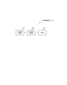
- FIG. 1 is a block diagram showing a functional configuration of an information processing system according to a first embodiment
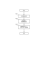
- FIG. 4 is a flow chart showing the flow of operations by the information processing system according to the first embodiment
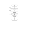
- 9 is a flow chart showing the flow of operations by the information processing system according to the second embodiment
- 10 is a flow chart showing the flow of operations by an information processing system according to the third embodiment
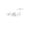
- FIG. 12 is a block diagram showing a functional configuration of an information processing system according to a fourth embodiment
- FIG. FIG. 14 is a flow chart showing the flow of operations by an information processing system according to the fourth embodiment
- FIG. 12 is a block diagram showing a functional configuration of an information processing system according to a fifth embodiment;
- FIG. 14 is a flow chart showing the flow of operations by the information processing system according to the fifth embodiment;
- FIG. 12 is a block diagram showing a functional configuration of an information processing system according to a sixth embodiment;
- FIG. 16 is a flow chart showing the flow of operations by an information processing system according to the sixth embodiment;
- FIG. 21 is a graph showing an example of skin reflectance calculated by the information processing system according to the sixth embodiment;
- FIG. FIG. 22 is a block diagram showing a functional configuration of an information processing system according to a seventh embodiment;
- FIG. FIG. 14 is a flow chart showing the flow of operations by an information processing system according to the seventh embodiment;
- FIG. FIG. 14 is a flow chart showing the flow of operations by an information processing system according to the eighth embodiment;
- FIG. It is a table
- FIG. 1 is a block diagram showing the hardware configuration of an information processing system according to the first embodiment.
- an information processing system 10 includes a processor 11, a RAM (Random Access Memory) 12, a ROM (Read Only Memory) 13, and a storage device .
- Information processing system 10 may further include an input device 15 and an output device 16 .
- the information processing system 10 may also include a camera 18 and lighting 19 .
- the above-described processor 11 , RAM 12 , ROM 13 , storage device 14 , input device 15 , output device 16 , camera 18 and illumination 19 are connected via data bus 17 .
- the processor 11 reads a computer program.
- processor 11 is configured to read a computer program stored in at least one of RAM 12, ROM 13 and storage device .
- the processor 11 may read a computer program stored in a computer-readable recording medium using a recording medium reader (not shown).
- the processor 11 may acquire (that is, read) a computer program from a device (not shown) arranged outside the information processing system 10 via a network interface.
- the processor 11 controls the RAM 12, the storage device 14, the input device 15 and the output device 16 by executing the read computer program.
- the processor 11 implements functional blocks for controlling the imaging of the object. That is, the processor 11 may function as a controller that executes each control in the information processing system 10 .
- the processor 11 may be configured as, for example, a CPU (Central Processing Unit), GPU (Graphics Processing Unit), FPGA (Field-Programmable Gate Array), DSP (Demand-Side Platform), and ASIC (Application Specific Integrate).
- the processor 11 may be configured with one of these, or may be configured to use a plurality of them in parallel.
- the RAM 12 temporarily stores computer programs executed by the processor 11.
- the RAM 12 temporarily stores data temporarily used by the processor 11 while the processor 11 is executing the computer program.
- the RAM 12 may be, for example, a D-RAM (Dynamic RAM).
- the ROM 13 stores computer programs executed by the processor 11 .
- the ROM 13 may also store other fixed data.
- the ROM 13 may be, for example, a P-ROM (Programmable ROM).
- the storage device 14 stores data that the information processing system 10 saves for a long period of time.
- Storage device 14 may act as a temporary storage device for processor 11 .
- the storage device 14 may include, for example, at least one of a hard disk device, a magneto-optical disk device, an SSD (Solid State Drive), and a disk array device.
- the input device 15 is a device that receives input instructions from the user of the information processing system 10 .
- Input device 15 may include, for example, at least one of a keyboard, mouse, and touch panel.
- the input device 15 may be configured as a mobile terminal such as a smart phone or a tablet.
- the output device 16 is a device that outputs information about the information processing system 10 to the outside.
- the output device 16 may be a display device (eg, display) capable of displaying information regarding the information processing system 10 .
- the output device 16 may be a speaker or the like capable of outputting information about the information processing system 10 by voice.
- the output device 16 may be configured as a mobile terminal such as a smart phone or a tablet.
- the camera 18 is a camera installed at a location capable of capturing a target image (for example, an image including the target's face or an image including the target's iris).
- a target image for example, an image including the target's face or an image including the target's iris.
- the camera 18 may be a camera mounted on a terminal (for example, smart phone) owned by the subject.
- the camera 18 may be a camera that captures still images or a camera that captures moving images.
- the camera 18 may be configured as a visible light camera, or may be configured as a near-infrared camera.
- a plurality of cameras 18 may be provided. When multiple cameras 18 are provided, they may be provided as different types of cameras 18 . For example, a visible light camera that images the target's face and a near-infrared camera that images the target's iris may be provided. Camera 18 may also be provided as a depth camera or a thermal camera.
- the lighting 19 is configured to be able to irradiate an object with illumination light when an image is captured by the camera 18 .
- the illumination 19 may be configured to emit visible light.
- a near-infrared camera is provided as the camera 18, the illumination 19 may be configured to irradiate near-infrared light.
- a plurality of lights 19 may be provided. When multiple lights 19 are provided, they may be provided as different types of lights 19 .
- FIG. 1 illustrates an example of the information processing system 10 including a plurality of devices, but all or part of these functions may be realized by one device (information processing device).
- This information processing apparatus is configured with, for example, only the processor 11, RAM 12, and ROM 13 described above, and the other components (that is, the storage device 14, the input device 15, the output device 16, and the camera 18) include, for example, information
- An external device connected to the processing device may be provided.
- the information processing device may implement a part of the arithmetic function by an external device (for example, an external server, a cloud, etc.).
- FIG. 2 is a block diagram showing the functional configuration of the information processing system according to the first embodiment.
- the information processing system 10 includes a skin color information acquisition unit 110, a luminance information estimation unit 120, and a control unit 130 as components for realizing the functions. configured with.
- Each of the skin color information acquiring unit 110, the luminance information estimating unit 120, and the control unit 130 may be processing blocks realized by, for example, the above-described processor 11 (see FIG. 1).
- the skin color information acquisition unit 110 is configured to be able to acquire skin color information regarding the skin color of the target (that is, the target imaged by the camera 18).
- the skin color information acquisition unit 110 may acquire skin color information from the target image.
- the skin color information acquisition unit 110 may acquire skin color information from the target face included in the visible light image.
- the skin color information acquisition unit 110 may have a function of detecting an area where the target face exists (that is, the face area).
- the skin color information acquisition unit 110 may detect a partial area of the target face and acquire the skin color information of that area.
- the skin color information acquisition unit 110 may acquire skin color information by detecting the target cheek region or forehead region.
- the skin color information acquisition unit 110 may detect the eyes and acquire the skin color information from the skin regions around the eyes. Skin color information may be acquired as RGB values, for example. Skin color information may be obtained as an average RGB value of a given area of interest (eg, face area).
- the skin color information acquired by the skin color information acquiring section 110 is configured to be output to the luminance information estimating section 120 .
- the luminance information estimation unit 120 is configured to be able to estimate the luminance information of the target skin (for example, the luminance information of the skin when the target is imaged) from the skin color information acquired by the skin color information acquisition unit 110. That is, the luminance information estimation unit 120 is configured to be able to estimate luminance information when it is assumed that imaging will be performed from now on without actually imaging the object.
- the brightness information may be, for example, pixel values or information including brightness values.
- the brightness information may be, for example, brightness information when an image is captured by a visible light camera, or may be brightness information when an image is captured by a near-infrared camera. A specific method for estimating luminance information from skin color information will be described in detail in another embodiment described later.
- the luminance information estimated by the luminance information estimation section 120 is configured to be output to the control section 130 .
- the control unit 130 is configured to be able to control camera parameters related to exposure when imaging an object based on the luminance information estimated by the luminance information estimation unit 120 .
- the camera parameters may include, for example, at least one of lens aperture, exposure time, and gain.
- the control unit 130 may control one type of camera parameter, or may control multiple types of camera parameters.
- the control unit 130 may control the camera parameters so that the brightness information of the object captured by the camera 18 has an appropriate value. For example, when the estimated luminance information is too large (that is, when it is too bright), the control unit 130 may control the camera parameters so that the luminance information becomes smaller. For example, the control unit 130 may reduce the aperture value, shorten the exposure time, or reduce the gain. Alternatively, if the estimated luminance information is too small (that is, too dark), the control unit 130 may control the camera parameters so that the luminance information increases. For example, the control unit 130 may increase the aperture value, lengthen the exposure time, or increase the gain.
- FIG. 3 is a flow chart showing the operation flow of the information processing system according to the first embodiment.
- the skin color information acquisition unit 110 first acquires target skin color information (step S101). Note that when the skin color information acquisition unit 110 acquires the skin color information from the target image, processing for capturing the target image (for example, processing for capturing the target face image) may be performed before this step.
- the luminance information estimation unit 120 estimates the luminance information of the target skin based on the skin color information acquired by the skin color information acquisition unit 110 (step S102). Based on the luminance information estimated by the luminance information estimation unit 120, the control unit 130 controls camera parameters related to exposure when imaging the object (step S103).
- the imaging of the target may actually be performed. That is, the object may be imaged by the camera 18 whose camera parameters are controlled.
- the control unit 130 may have a function of outputting an imaging instruction to the camera after controlling the camera parameters. Images captured by the camera 18 may be used for biometric authentication, for example.
- biometric authentication may be multimodal authentication in which authentication is performed at a plurality of sites. For example, face authentication using a face image captured when acquiring skin color information and iris authentication using an iris image captured after control may be performed.
- camera parameters related to exposure when capturing an image of a target are controlled based on luminance information estimated from skin color information of the target. .
- luminance information estimated from skin color information of the target.
- the control unit 130 is configured to be able to control the lighting 19 when imaging the object based on the luminance information estimated by the luminance information estimation unit 120 .
- the control unit 130 may be configured to be able to control the amount of light, the direction of the lighting 19, or the timing of lighting.
- the controller 130 may be configured to be able to control each of the lights 19 .
- the control unit 130 may control the illumination 19 so that the luminance information of the object captured by the camera 18 has an appropriate value. For example, when the estimated luminance information is too large (that is, when it is too bright), the control unit 130 may control the lighting 19 so that the luminance information becomes smaller.
- control unit 130 may control the amount of light of the illumination 19 to be weak, direct the illumination 19 away from the target, or control the timing of illumination to be removed from the imaging timing.
- the controller 130 may control the lighting 19 so that the luminance information is increased.
- the control unit 130 may increase the amount of light of the illumination 19, direct the illumination 19 toward the target side, or bring the timing of illumination closer to the imaging timing.
- FIG. 4 is a flow chart showing the operation flow of the information processing system according to the second embodiment.
- the same reference numerals are assigned to the same processes as those described in FIG.
- the skin color information acquisition unit 110 first acquires target skin color information (step S101).
- the luminance information estimation unit 120 estimates the luminance information of the target skin based on the skin color information acquired by the skin color information acquisition unit 110 (step S102). Then, based on the luminance information estimated by the luminance information estimation unit 120, the control unit 130 controls the illumination 19 when imaging the object (step S201).
- the illumination 19 when imaging the target is controlled based on luminance information estimated from the skin color information of the target. By doing so, it is possible to image the object under appropriate conditions. Therefore, it is possible to prevent overexposure caused by saturation of pixel values, for example.
- the illumination 19 is controlled without actually capturing an image of the object (that is, by estimating luminance information), so that it is possible to capture an appropriate image while avoiding image capturing delays. can.
- the control unit 130 according to the third embodiment is configured to be able to control the camera parameters and the lighting 19 related to exposure when imaging the object based on the luminance information estimated by the luminance information estimation unit 120 . That is, the control unit 130 according to the third embodiment is configured to be able to execute both the control of the camera parameters described in the first embodiment and the control of the lighting 19 described in the second embodiment. Note that the control unit 130 may be configured to be able to execute coordinated control of the camera parameters and the lighting 19 . Specifically, the control unit 130 may perform control so as to make up for a deficiency caused by controlling one of the camera parameters and the lighting 19 by controlling the other.
- control unit 130 may control the camera parameters so that the brightness information becomes smaller, and also control the illumination 19 so that the brightness information becomes smaller.
- control unit 130 may perform control such that the excess due to control of one of the camera parameters and the lighting 19 is offset by control of the other.
- control unit 130 may control the camera parameters so that the brightness information becomes smaller, while controlling the illumination 19 so that the brightness information becomes slightly larger.
- FIG. 5 is a flow chart showing the operation flow of the information processing system according to the third embodiment.
- the same reference numerals are given to the same processes as those shown in FIG.
- the skin color information acquisition unit 110 first acquires target skin color information (step S101).
- the luminance information estimation unit 120 estimates the luminance information of the target skin based on the skin color information acquired by the skin color information acquisition unit 110 (step S102). Based on the luminance information estimated by the luminance information estimation unit 120, the control unit 130 controls the camera parameters and the illumination 19 when imaging the object (step S301).
- camera parameters and lighting 19 when capturing an image of the target are controlled based on luminance information estimated from the skin color information of the target. By doing so, it is possible to image the object under appropriate conditions. Therefore, it is possible to prevent overexposure caused by saturation of pixel values, for example.
- the camera parameters and lighting 19 are controlled without actually capturing an image of the object (that is, by estimating luminance information). can do.
- control can be performed with a higher degree of freedom than when only one of them is controlled.
- FIG. 6 An information processing system 10 according to the fourth embodiment will be described with reference to FIGS. 6 and 7.
- FIG. 6 It should be noted that the fourth embodiment may differ from the above-described first to third embodiments only in a part of configuration and operation, and other parts may be the same as those of the first to third embodiments. Therefore, in the following, portions different from the already described embodiments will be described in detail, and descriptions of other overlapping portions will be omitted as appropriate.
- FIG. 6 is a block diagram showing the functional configuration of an information processing system according to the fourth embodiment.
- symbol is attached
- the information processing system 10 includes a skin color information acquisition unit 110, a brightness information estimation unit 120, and a control unit 130 as components for realizing the functions thereof. configured with.
- the control unit 130 according to the fourth embodiment includes a threshold storage unit 131.
- the threshold storage unit 131 is configured to be able to store a first threshold and a second threshold used when controlling at least one of the camera parameters and the lighting 19 .
- the first threshold and the second threshold are thresholds indicating the upper limit and the lower limit of the target value of the luminance information. , at least one of the camera parameters and the lighting 19 is configured to be controllable.
- the first threshold and the second threshold may be values calculated by prior simulation or the like. For example, the first threshold and the second threshold may be set to values that do not saturate the pixel values of the target image. Multiple sets of the first threshold and the second threshold may be prepared. In this case, the actually used first threshold and second threshold may be changed (selected) according to the target skin color information and luminance information.
- the first threshold and the second threshold may be values that can be appropriately set by the user (for example, values input by user's operation).
- the first threshold and the second threshold may be values that are appropriately calculated based on information about the imaging environment, information about the object, or the like.
- the threshold storage unit 131 may be configured to have a function of calculating the first threshold and the second threshold.
- FIG. 7 is a flow chart showing the operation flow of the information processing system according to the fourth embodiment.
- the same reference numerals are given to the same processes as those shown in FIG.
- the skin color information acquisition unit 110 first acquires target skin color information (step S101). Then, the luminance information estimation unit 120 estimates the luminance information of the target skin based on the skin color information acquired by the skin color information acquisition unit 110 (step S102).
- control unit 130 reads the first threshold and the second threshold from the threshold storage unit 131 (step S401). Then, the control unit 130 controls at least one of the camera parameters and the illumination 19 when imaging the target so that the brightness information of the target skin is between the first threshold and the second threshold. (step S402).
- the luminance information of the skin of the target is between the first threshold and the second threshold.
- camera parameters and/or lighting 19 are controlled. In this way, it becomes possible to control at least one of the camera parameters and the illumination 19 more easily and accurately.
- FIG. 8 An information processing system 10 according to the fifth embodiment will be described with reference to FIGS. 8 and 9.
- FIG. 8 It should be noted that the fifth embodiment may differ from the above-described first to fourth embodiments only in a part of configuration and operation, and other parts may be the same as those of the first to fourth embodiments. Therefore, in the following, portions different from the already described embodiments will be described in detail, and descriptions of other overlapping portions will be omitted as appropriate.
- FIG. 8 is a block diagram showing the functional configuration of an information processing system according to the fifth embodiment.
- symbol is attached
- the information processing system 10 includes a skin color information acquisition unit 110, a brightness information estimation unit 120, and a control unit 130 as components for realizing the functions. configured with.
- the brightness information estimation unit 120 according to the fifth embodiment includes a reflectance acquisition unit 121 .
- the reflectance acquisition unit 121 is configured to be able to acquire the skin reflectance according to the skin color information acquired by the skin color information acquisition unit 110 .
- the "skin reflectance" here indicates the ratio of the light irradiated to the skin and the light reflected from the skin.
- the skin reflectance may be obtained, for example, for each wavelength of irradiated light.
- the skin reflectance in the near-infrared region may be acquired. A more specific method of acquiring the reflectance of the skin will be described in detail in another embodiment described later.
- the luminance information estimation unit 120 according to the fifth embodiment is configured to be able to estimate the luminance information of the target skin based on the reflectance of the skin acquired by the reflectance acquisition unit 121 .
- FIG. 9 is a flow chart showing the operation flow of the information processing system according to the fifth embodiment.
- the same reference numerals are assigned to the same processes as those shown in FIG.
- the skin color information acquisition unit 110 first acquires target skin color information (step S101). Then, the reflectance acquisition unit 121 acquires the reflectance of the target skin based on the skin color information acquired by the skin color information acquisition unit 110 (step S501).
- the luminance information estimation unit 120 estimates the luminance information of the target skin based on the skin reflectance acquired by the reflectance acquisition unit 121 (step S502). Based on the luminance information estimated by the luminance information estimation unit 120, the control unit 130 controls at least one of the camera parameters and the illumination 19 when imaging the object (step S503).
- the information processing system 10 estimates the luminance information of the target skin based on the reflectance of the skin. By doing so, it is possible to accurately estimate the luminance information of the target skin. Therefore, it becomes possible to control at least one of the camera parameters and the illumination 19 more appropriately.
- FIG. 10 An information processing system 10 according to the sixth embodiment will be described with reference to FIGS. 10 to 12.
- FIG. The sixth embodiment may differ from the above-described fifth embodiment only in a part of configuration and operation, and the other parts may be the same as those of the first to fifth embodiments. Therefore, in the following, portions different from the already described embodiments will be described in detail, and descriptions of other overlapping portions will be omitted as appropriate.
- FIG. 10 is a block diagram showing the functional configuration of an information processing system according to the sixth embodiment.
- symbol is attached
- the information processing system 10 includes a skin color information acquiring unit 110, a brightness information estimating unit 120, a control unit 130, and a reflecting unit as components for realizing its functions. and a rate model storage unit 140 . That is, the information processing system 10 according to the sixth embodiment further includes a reflectance model storage unit 140 in addition to the configuration of the fifth embodiment (see FIG. 8).
- the reflectance model storage unit 140 may be implemented by, for example, the above storage device 14 (see FIG. 1).
- the reflectance model storage unit 140 is configured to be able to store a reflectance model for calculating skin reflectance from the skin color information acquired by the skin color information acquisition unit 110 .
- a reflectance model may be generated in advance, for example, based on data obtained from a plurality of living bodies. Also, the reflectance model may be a model generated by machine learning. A specific example of the reflectance model will be described later in detail. Note that the reflectance acquisition unit 121 according to the sixth embodiment is configured to be able to calculate the reflectance of the skin using the reflectance model read from the reflectance model storage unit 140 .
- FIG. 11 is a flow chart showing the operation flow of the information processing system according to the sixth embodiment.
- the same reference numerals are given to the same processes as those shown in FIG.
- the skin color information acquisition unit 110 first acquires target skin color information (step S101). Then, the reflectance acquisition unit 121 uses the reflectance model stored in the reflectance model storage unit 140 to calculate the reflectance of the target skin (step S601). That is, the reflectance acquisition unit 121 calculates the reflectance of the target skin based on the skin color information and the reflectance model.
- the luminance information estimation unit 120 estimates the luminance information of the target skin based on the reflectance of the skin calculated by the reflectance acquisition unit 121 (step S502). Based on the luminance information estimated by the luminance information estimation unit 120, the control unit 130 controls at least one of the camera parameters and the illumination 19 when imaging the object (step S503).
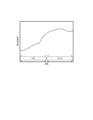
- FIG. 12 is a graph showing an example of skin reflectance calculated by the information processing system according to the sixth embodiment. Note that the vertical axis of the graph shown in FIG. 12 is the "skin reflectance" and the horizontal axis is the "(light) wavelength”.
- the reflectance acquisition unit 121 calculates the tristimulus values XYZ from the RGB values described above.
- the tristimulus values XYZ can be calculated using, for example, the following formula (1).
- transformation matrix aij may use a matrix defined in the standard RGB space sRGB.
- the reflectance acquisition unit 121 estimates the skin reflectance S( ⁇ ) from the calculated tristimulus values XYZ. Specifically, the characteristic parameters (a, b, c) are calculated using the following formula (2).
- the reflectance acquisition unit 121 obtains the reflectance of the skin by substituting the calculated characteristic parameters (a, b, c) into the reflectance model. Specifically, the reflectance S( ⁇ ) is obtained by substituting the characteristic parameters (a, b, c) into the following equation (3). As shown in FIG. 12, the skin reflectance S( ⁇ ) may be obtained from the visible light region to the near-infrared light region.
- the information processing system 10 calculates the reflectance of the target skin using the reflectance model. By doing so, the reflectance of the skin can be calculated easily and accurately. Therefore, the luminance information of the skin can be estimated with high accuracy, and at least one of the camera parameters and the illumination 19 can be controlled more appropriately.
- the information processing system 10 according to the sixth embodiment in multimodal authentication using a face and an iris, when the camera that photographs the face photographs with visible light and the camera that photographs the iris photographs with near-infrared light, From the skin color information obtained from the face image captured in the visible light range, it is possible to obtain the skin brightness information in the near-infrared light range. Camera parameters and/or lighting of the imaging camera can be appropriately controlled.
- FIG. 13 An information processing system 10 according to the seventh embodiment will be described with reference to FIGS. 13 and 14.
- FIG. It should be noted that the seventh embodiment may differ from the first to sixth embodiments described above only in a part of configuration and operation, and other parts may be the same as those of the first to sixth embodiments. Therefore, in the following, portions different from the already described embodiments will be described in detail, and descriptions of other overlapping portions will be omitted as appropriate.
- FIG. 13 is a block diagram showing the functional configuration of an information processing system according to the seventh embodiment.
- symbol is attached
- the information processing system 10 according to the seventh embodiment includes a skin color information obtaining unit 110, a luminance information estimating unit 120, a control unit 130, and a moving unit as components for realizing the functions thereof. and an amount detection unit 150 . That is, the information processing system 10 according to the seventh embodiment further includes a movement amount detection unit 150 in addition to the configuration of the first embodiment (see FIG. 2).
- the movement amount detection unit 150 is configured to be able to detect the movement amount of the object. More specifically, the movement amount detection unit 150 may be configured to be able to detect the movement amount (in other words, movement speed) of the object per unit time. The movement amount detection unit 150 may be configured to detect the movement amount of the object using various sensors. Alternatively, the movement amount detection unit 150 may capture a plurality of images of the target and detect the movement amount of the target based on the difference between those images (specifically, the change in the position of the target in the image). good. The amount of movement of the object detected by the movement amount detection unit 150 is configured to be output to the control unit 130 .
- the control unit 130 determines at least one of the camera parameters and the illumination 19 based on the amount of movement detected by the movement amount detection unit 150 in addition to the luminance information estimated by the luminance information estimation unit 120. configured to be controllable.
- the control unit 130 may change the control amount according to, for example, the detected amount of movement of the target. That is, the control amount of the camera parameters and the lighting 19 may be increased or decreased according to the amount of movement of the object.
- the control unit 130 may change the type of parameter to be controlled according to the detected amount of movement of the target. For example, when the amount of movement of the object is large, it is not preferable to increase the shutter speed (exposure time) (there is a risk of blurring), so other parameters may be controlled.
- control may be performed so that the light amount of the illumination 19 is increased while the shutter speed is shortened. Further, when the amount of movement of the object is small, control may be performed so that the light amount of the illumination 19 is weakened while the shutter speed is lengthened.
- FIG. 14 is a flow chart showing the operation flow of the information processing system according to the seventh embodiment.
- the same reference numerals are assigned to the same processes as those shown in FIG.
- the skin color information acquisition unit 110 first acquires target skin color information (step S101). Then, the luminance information estimation unit 120 estimates the luminance information of the target skin based on the skin color information acquired by the skin color information acquisition unit 110 (step S102).
- the movement amount detection unit 150 detects the movement amount of the target (step S701). Note that the movement amount detection may be performed in parallel with steps S101 and S102 described above, or may be performed in parallel.
- control unit 130 adjusts at least one of the camera parameters and the illumination 19 when imaging the target based on the luminance information estimated by the luminance information estimation unit 120 and the movement amount detected by the movement amount detection unit. control (step S2702).
- At least one of the camera parameters and the lighting 19 when capturing an image of the target is controlled in consideration of the amount of movement of the target. . In this way, at least one of the camera parameters and the lighting 19 can be controlled more appropriately than when the movement amount of the object is not considered.
- FIG. 15 is a flow chart showing the operation flow of the information processing system according to the eighth embodiment.
- the same reference numerals are given to the same processes as those shown in FIG.
- the skin color information acquisition unit 110 first acquires target skin color information (step S101). Then, the luminance information estimation unit 120 estimates the luminance information of the target skin based on the skin color information acquired by the skin color information acquisition unit 110 (step S102).
- control unit 130 controls at least one of the camera parameters and the illumination 19 when capturing an image of the target based on the brightness information estimated by the brightness information estimation unit 120 (step S801). Then, in the information processing system 10 according to the present embodiment, in particular, it is determined whether or not all imaging is completed in the imaging performed after the control (step S802). That is, it is determined whether to end the imaging of the current object or continue to image the current object. Whether or not to finish imaging the target depends on the number of images captured so far (for example, whether the number of captured images has reached a predetermined number) or the position of the target (for example, whether the target has moved out of the imaging range). or not).
- step S802 If it is determined to end the imaging of the target (step S802: YES), the series of operations will end. On the other hand, if it is determined not to finish imaging the target (step S802: NO), the process starts again from step S101.
- at least one of the camera parameters and the lighting 19 is controlled each time the image is captured. For example, when an object moves closer to the camera 18, the shutter speed may be controlled to be shortened as the object approaches. Also, in such a case, the lighting 19 may be controlled to gradually brighten in order to reduce the influence of the shortening of the shutter speed.
- At least one of camera parameters and lighting 19 is controlled for each imaging. In this way, since control is performed as needed according to the situation, it is possible to image the object under more appropriate conditions.
- FIG. 10 An information processing system 10 according to the ninth embodiment will be described with reference to FIG.
- the ninth embodiment describes a specific example of the control operation of the eighth embodiment described above, and other parts may be the same as those of the first to seventh embodiments. Therefore, in the following, portions different from the already described embodiments will be described in detail, and descriptions of other overlapping portions will be omitted as appropriate.
- FIG. 16 is a table showing an example of control operations by the information processing system according to the ninth embodiment.
- the control unit 130 controls the exposure time (shutter speed) of the camera 18 and the illumination 19 based on the luminance information estimated by the luminance information estimation unit 120. and control. Specifically, the control unit 130 according to the ninth embodiment executes a first control that shortens the exposure time and brightens the illumination 19, and a second control that lengthens the exposure time and darkens the illumination 19. It is possible. In the first control, the brightness of the lighting 19 may be controlled so that the image becomes too dark, taking into consideration the effect on the image due to the shortening of the exposure time.
- the brightness of the lighting 19 may be controlled so that the image does not become too bright, taking into consideration the effect on the image due to the longer exposure time.
- the brightness of the lighting 19 may be controlled by adjusting the direction of the lighting 19 and the lighting timing, in addition to adjusting the amount of light, as described in the above-described other embodiments.
- the first control and the second control are executed for each imaging. Therefore, when the first control is executed for each image capturing, the exposure time is gradually shortened as the image capturing progresses, while the illumination 19 is controlled to gradually become brighter. Further, when the second control is executed for each image capturing, the exposure time is gradually lengthened as the image capturing progresses, while the lighting 19 is controlled to gradually darken. It should be noted that which of the first control and the second control is to be executed may be changed during imaging. For example, the second control may be executed after the first control is executed. Also, the first control may be executed after the second control is executed. The timing of switching between the first control and the second control may be determined by luminance information estimated by the information estimation section 120, for example.
- the exposure time of the camera 18 and the brightness of the lighting 19 are controlled based on the luminance information. In this way, coordinated control of the camera parameters and the illumination 19 is performed, so that the target can be imaged under more appropriate conditions.
- a processing method of recording a program for operating the configuration of each embodiment so as to realize the functions of each embodiment described above on a recording medium, reading the program recorded on the recording medium as a code, and executing it on a computer is also implemented. Included in the category of form. That is, a computer-readable recording medium is also included in the scope of each embodiment. In addition to the recording medium on which the above program is recorded, the program itself is also included in each embodiment.
- a floppy (registered trademark) disk, hard disk, optical disk, magneto-optical disk, CD-ROM, magnetic tape, non-volatile memory card, and ROM can be used as recording media.
- the program recorded on the recording medium alone executes the process, but also the one that operates on the OS and executes the process in cooperation with other software and functions of the expansion board. included in the category of Furthermore, the program itself may be stored on the server, and part or all of the program may be downloaded from the server to the user terminal.
- the information processing system includes acquisition means for acquiring skin color information that is information about a skin color of a target, estimation means for estimating luminance information of the target skin based on the skin color information, and An information processing system comprising control means for controlling at least one of camera parameters and illumination related to exposure when imaging the object based on luminance information.
- Appendix 2 In the information processing system according to appendix 2, the control means controls at least one of the camera parameter and the illumination so that the brightness information of the target skin is between a first threshold and a second threshold. , and an information processing system according to appendix 1.
- the information processing system according to appendix 3 is the information processing system according to appendix 1 or 2, wherein the estimation means estimates the luminance information based on the reflectance of the target skin according to the skin color information. be.
- the information processing system according to appendix 4 further includes storage means for storing a reflectance model for calculating the reflectance of the skin from the skin color information, and the estimation means stores the skin calculated using the reflectance model. 3.
- the information processing system according to appendix 5 further includes detection means for detecting a movement amount of the object, and the control means detects at least one of the camera parameter and the illumination based on the luminance information and the movement amount. 5.
- Appendix 6 The information processing system according to any one of appendices 1 to 5, wherein the control means controls at least one of the camera parameter and the illumination for each imaging when the object is imaged multiple times.
- control means shortens the exposure time when imaging the object for each imaging and brightens the illumination based on the luminance information, or performs imaging 7.
- second control is performed such that the exposure time is lengthened and the illumination is darkened every time the object is imaged.
- the information processing apparatus includes acquisition means for acquiring skin color information that is information about a skin color of a target, estimation means for estimating luminance information of the target skin based on the skin color information, and and a control means for controlling at least one of camera parameters and lighting for exposure when imaging the object based on luminance information.
- the information processing method according to appendix 9 is an information processing method executed by at least one computer, in which skin color information that is information about the skin color of a target is acquired, and based on the skin color information, the skin of the target is and controlling at least one of camera parameters relating to exposure when imaging the object and illumination based on the luminance information.
- At least one computer acquires skin color information that is information about a skin color of a target, estimates brightness information of the skin of the target based on the skin color information, and estimates the brightness of the skin of the target based on the skin color information.
- a recording medium recording a computer program for executing an information processing method for controlling at least one of camera parameters and lighting for exposure when imaging the object based on the information.
- the computer program according to attachment 11 acquires skin color information, which is information about a skin color of a target, in at least one computer, estimates brightness information of the skin of the target based on the skin color information, and estimates the brightness of the skin of the target based on the skin color information.
Landscapes
- Engineering & Computer Science (AREA)
- Multimedia (AREA)
- Signal Processing (AREA)
- Computer Vision & Pattern Recognition (AREA)
- Physics & Mathematics (AREA)
- General Physics & Mathematics (AREA)
- Theoretical Computer Science (AREA)
- Measurement Of The Respiration, Hearing Ability, Form, And Blood Characteristics Of Living Organisms (AREA)
Priority Applications (3)
| Application Number | Priority Date | Filing Date | Title |
|---|---|---|---|
| PCT/JP2021/036237 WO2023053383A1 (ja) | 2021-09-30 | 2021-09-30 | 情報処理システム、情報処理装置、情報処理方法、及び記録媒体 |
| JP2023550942A JP7694682B2 (ja) | 2021-09-30 | 2021-09-30 | 情報処理システム、情報処理装置、情報処理方法、及び記録媒体 |
| US17/775,969 US12192642B2 (en) | 2021-09-30 | 2021-09-30 | Information processing system, information processing apparatus, information processing method and recording medium |
Applications Claiming Priority (1)
| Application Number | Priority Date | Filing Date | Title |
|---|---|---|---|
| PCT/JP2021/036237 WO2023053383A1 (ja) | 2021-09-30 | 2021-09-30 | 情報処理システム、情報処理装置、情報処理方法、及び記録媒体 |
Publications (1)
| Publication Number | Publication Date |
|---|---|
| WO2023053383A1 true WO2023053383A1 (ja) | 2023-04-06 |
Family
ID=85781620
Family Applications (1)
| Application Number | Title | Priority Date | Filing Date |
|---|---|---|---|
| PCT/JP2021/036237 Ceased WO2023053383A1 (ja) | 2021-09-30 | 2021-09-30 | 情報処理システム、情報処理装置、情報処理方法、及び記録媒体 |
Country Status (3)
| Country | Link |
|---|---|
| US (1) | US12192642B2 (https=) |
| JP (1) | JP7694682B2 (https=) |
| WO (1) | WO2023053383A1 (https=) |
Families Citing this family (1)
| Publication number | Priority date | Publication date | Assignee | Title |
|---|---|---|---|---|
| JP7811724B2 (ja) * | 2021-10-01 | 2026-02-06 | パナソニックIpマネジメント株式会社 | 撮像誘導装置、撮像誘導方法及びプログラム |
Citations (4)
| Publication number | Priority date | Publication date | Assignee | Title |
|---|---|---|---|---|
| JP2005094133A (ja) * | 2003-09-12 | 2005-04-07 | Fuji Photo Film Co Ltd | 撮影装置 |
| JP2008187318A (ja) * | 2007-01-29 | 2008-08-14 | Fujifilm Corp | 撮影装置およびその制御方法並びにプログラム |
| JP2010183459A (ja) * | 2009-02-06 | 2010-08-19 | Canon Inc | 撮像装置及びその制御方法 |
| JP2016009998A (ja) * | 2014-06-24 | 2016-01-18 | キヤノン株式会社 | 撮像装置、撮像方法及びプログラム |
Family Cites Families (9)
| Publication number | Priority date | Publication date | Assignee | Title |
|---|---|---|---|---|
| JP4665780B2 (ja) * | 2006-01-30 | 2011-04-06 | ソニー株式会社 | 顔重要度判定装置、方法、および撮像装置 |
| US20080055476A1 (en) * | 2006-09-01 | 2008-03-06 | Texas Instruments Incorporated | Video processing |
| US7847830B2 (en) * | 2006-11-21 | 2010-12-07 | Sony Ericsson Mobile Communications Ab | System and method for camera metering based on flesh tone detection |
| JP2008164731A (ja) * | 2006-12-27 | 2008-07-17 | Fujifilm Corp | 撮影装置及びその制御方法 |
| JP5438239B1 (ja) | 2012-11-10 | 2014-03-12 | トレンドサイン株式会社 | シコニン誘導体を有するペリオスチンの発現抑制剤 |
| CN104780834B (zh) | 2012-11-12 | 2016-12-28 | 阿尔卑斯电气株式会社 | 生物体信息计测装置及使用该装置的输入装置 |
| US9672341B2 (en) | 2014-10-30 | 2017-06-06 | Delta ID Inc. | Systems and methods for spoof detection in iris based biometric systems |
| CN114341923A (zh) | 2019-09-04 | 2022-04-12 | 日本电气株式会社 | 控制设备、控制方法和存储介质 |
| SE2351197A1 (en) * | 2021-04-19 | 2023-10-18 | Hanwha Vision Co Ltd | Adjustment of shutter value of surveillance camera via ai-based object recognition |
-
2021
- 2021-09-30 US US17/775,969 patent/US12192642B2/en active Active
- 2021-09-30 WO PCT/JP2021/036237 patent/WO2023053383A1/ja not_active Ceased
- 2021-09-30 JP JP2023550942A patent/JP7694682B2/ja active Active
Patent Citations (4)
| Publication number | Priority date | Publication date | Assignee | Title |
|---|---|---|---|---|
| JP2005094133A (ja) * | 2003-09-12 | 2005-04-07 | Fuji Photo Film Co Ltd | 撮影装置 |
| JP2008187318A (ja) * | 2007-01-29 | 2008-08-14 | Fujifilm Corp | 撮影装置およびその制御方法並びにプログラム |
| JP2010183459A (ja) * | 2009-02-06 | 2010-08-19 | Canon Inc | 撮像装置及びその制御方法 |
| JP2016009998A (ja) * | 2014-06-24 | 2016-01-18 | キヤノン株式会社 | 撮像装置、撮像方法及びプログラム |
Also Published As
| Publication number | Publication date |
|---|---|
| JPWO2023053383A1 (https=) | 2023-04-06 |
| US12192642B2 (en) | 2025-01-07 |
| US20240155244A1 (en) | 2024-05-09 |
| JP7694682B2 (ja) | 2025-06-18 |
Similar Documents
| Publication | Publication Date | Title |
|---|---|---|
| CN106664364B (zh) | 图像处理设备及其控制方法和摄像设备 | |
| JP6576083B2 (ja) | 画像処理装置、画像処理方法、およびプログラム | |
| WO2019011147A1 (zh) | 逆光场景的人脸区域处理方法和装置 | |
| CN108337450B (zh) | 图像处理装置、图像处理方法以及记录介质 | |
| WO2017203913A1 (ja) | 肌診断装置および肌診断方法 | |
| JP7401013B2 (ja) | 情報処理装置、制御装置、情報処理方法及びプログラム | |
| JP6412386B2 (ja) | 画像処理装置およびその制御方法、プログラムならびに記録媒体 | |
| US20150243027A1 (en) | Image processing device, image processing method, and program | |
| JP7114335B2 (ja) | 画像処理装置、画像処理装置の制御方法、及び、プログラム | |
| JP6740109B2 (ja) | 画像処理装置、画像処理方法、およびプログラム | |
| JP7694682B2 (ja) | 情報処理システム、情報処理装置、情報処理方法、及び記録媒体 | |
| JP6384205B2 (ja) | 画像処理装置、撮像装置、画像処理方法、及びプログラム | |
| JP6354118B2 (ja) | 画像処理装置、画像処理方法及びプログラム | |
| JP2019205205A (ja) | 画像処理装置、画像処理方法、およびプログラム | |
| JP2021010652A (ja) | 情報処理装置、評価方法、および情報処理プログラム | |
| JP5103984B2 (ja) | 画像処理装置、撮像装置、および画像処理プログラム | |
| JP7289308B2 (ja) | 画像解析装置、画像解析方法およびプログラム | |
| JP2018098744A (ja) | 画像処理装置、及び画像処理方法 | |
| JP7102192B2 (ja) | 画像処理装置、その制御方法、プログラム | |
| US20200077008A1 (en) | Image processing apparatus, image processing method, and storage medium | |
| WO2023166556A1 (ja) | 情報処理システム、情報処理方法、及び記録媒体 | |
| JP7289309B2 (ja) | 画像解析装置、画像解析方法およびプログラム | |
| JP6675461B2 (ja) | 画像処理装置およびその制御方法、ならびにプログラム | |
| JP2012079244A (ja) | 静脈パターン検出装置、静脈認証装置及び静脈パターン検出方法 | |
| WO2018180860A1 (ja) | 画像処理装置、画像処理方法、及びプログラム |
Legal Events
| Date | Code | Title | Description |
|---|---|---|---|
| WWE | Wipo information: entry into national phase |
Ref document number: 17775969 Country of ref document: US |
|
| WWE | Wipo information: entry into national phase |
Ref document number: 2023550942 Country of ref document: JP |
|
| NENP | Non-entry into the national phase |
Ref country code: DE |
|
| 122 | Ep: pct application non-entry in european phase |
Ref document number: 21959418 Country of ref document: EP Kind code of ref document: A1 |