WO2023053206A1 - Vehicle power supply system - Google Patents
Vehicle power supply system Download PDFInfo
- Publication number
- WO2023053206A1 WO2023053206A1 PCT/JP2021/035641 JP2021035641W WO2023053206A1 WO 2023053206 A1 WO2023053206 A1 WO 2023053206A1 JP 2021035641 W JP2021035641 W JP 2021035641W WO 2023053206 A1 WO2023053206 A1 WO 2023053206A1
- Authority
- WO
- WIPO (PCT)
- Prior art keywords
- battery pack
- converter
- fan
- vehicle
- power supply
- Prior art date
Links
- 238000001816 cooling Methods 0.000 abstract description 78
- 239000004020 conductor Substances 0.000 description 2
- 230000008878 coupling Effects 0.000 description 2
- 238000010168 coupling process Methods 0.000 description 2
- 238000005859 coupling reaction Methods 0.000 description 2
- 238000007599 discharging Methods 0.000 description 2
- 238000010586 diagram Methods 0.000 description 1
- 230000000694 effects Effects 0.000 description 1
- 238000000034 method Methods 0.000 description 1
Images


Classifications
-
- B—PERFORMING OPERATIONS; TRANSPORTING
- B60—VEHICLES IN GENERAL
- B60L—PROPULSION OF ELECTRICALLY-PROPELLED VEHICLES; SUPPLYING ELECTRIC POWER FOR AUXILIARY EQUIPMENT OF ELECTRICALLY-PROPELLED VEHICLES; ELECTRODYNAMIC BRAKE SYSTEMS FOR VEHICLES IN GENERAL; MAGNETIC SUSPENSION OR LEVITATION FOR VEHICLES; MONITORING OPERATING VARIABLES OF ELECTRICALLY-PROPELLED VEHICLES; ELECTRIC SAFETY DEVICES FOR ELECTRICALLY-PROPELLED VEHICLES
- B60L50/00—Electric propulsion with power supplied within the vehicle
- B60L50/50—Electric propulsion with power supplied within the vehicle using propulsion power supplied by batteries or fuel cells
- B60L50/60—Electric propulsion with power supplied within the vehicle using propulsion power supplied by batteries or fuel cells using power supplied by batteries
-
- B—PERFORMING OPERATIONS; TRANSPORTING
- B60—VEHICLES IN GENERAL
- B60L—PROPULSION OF ELECTRICALLY-PROPELLED VEHICLES; SUPPLYING ELECTRIC POWER FOR AUXILIARY EQUIPMENT OF ELECTRICALLY-PROPELLED VEHICLES; ELECTRODYNAMIC BRAKE SYSTEMS FOR VEHICLES IN GENERAL; MAGNETIC SUSPENSION OR LEVITATION FOR VEHICLES; MONITORING OPERATING VARIABLES OF ELECTRICALLY-PROPELLED VEHICLES; ELECTRIC SAFETY DEVICES FOR ELECTRICALLY-PROPELLED VEHICLES
- B60L58/00—Methods or circuit arrangements for monitoring or controlling batteries or fuel cells, specially adapted for electric vehicles
- B60L58/10—Methods or circuit arrangements for monitoring or controlling batteries or fuel cells, specially adapted for electric vehicles for monitoring or controlling batteries
- B60L58/24—Methods or circuit arrangements for monitoring or controlling batteries or fuel cells, specially adapted for electric vehicles for monitoring or controlling batteries for controlling the temperature of batteries
- B60L58/26—Methods or circuit arrangements for monitoring or controlling batteries or fuel cells, specially adapted for electric vehicles for monitoring or controlling batteries for controlling the temperature of batteries by cooling
Definitions
- the present invention relates to a vehicle power supply system.
- Patent Document 1 a power supply system arranged inside a vehicle such as an automobile is known (see Patent Document 1, for example).
- the battery pack is arranged below the front seats, a fan is arranged in front of the battery pack and below the front seats, and a cooling duct is connected between the fan and the battery pack. ing.
- the battery pack may protrude into the rear seats.
- the fan may have to be arranged so as to protrude toward the rear seats. If the components that make up the power supply system for a vehicle are arranged so as to protrude from the rear seat side, the space on the rear seat side becomes narrow.
- the present invention has been made in view of the above problems, and its purpose is to arrange the components that make up the vehicle power supply system under the floor without narrowing the space on the rear seat side.
- a vehicle power supply system includes a battery pack arranged below a pair of left and right front seats.
- a fan is arranged above the battery pack and between a pair of left and right front seats.
- a vehicle power supply system includes a battery pack arranged below a pair of left and right front seats, and a battery pack arranged below one of the pair of left and right front seats. and a service disconnect switch.
- a converter is arranged in front of the battery pack, and a fan is arranged above the battery pack and between a pair of left and right front seats.
- a first duct connects the battery pack and the fan, and a second duct connects the converter and the fan.
- the components that make up the vehicle power supply system can be arranged under the floor without narrowing the space on the rear seat side.
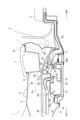
- FIG. 1 is a side cross-sectional view of a vehicle power supply system according to an embodiment of the present invention.
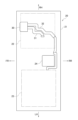
- 2 is a schematic plan view of the battery pack shown in FIG. 1.
- FIG. 3 is a schematic diagram showing the electrical connection between the battery inside the battery pack and the service disconnect switch.
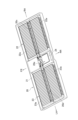
- FIG. 4 is a schematic perspective view of a battery pack.
- FIG. 5 is a schematic perspective view showing the internal structure of the battery pack.
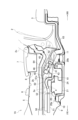
- FIG. 6 is a side sectional view of a vehicle power supply system according to another embodiment of the present invention.
- FIG. 1 indicates the front side of the vehicle
- RR indicates the rear side of the vehicle
- RH indicates the right side in the vehicle width direction
- LH indicates the left side in the vehicle width direction.
- the vehicle power supply system 1 is applied to so-called left-hand drive vehicles.
- the steering wheel (not shown) and the driver's seat are arranged in the left part of the vehicle interior, and the passenger's seat is arranged in the right part of the vehicle interior.
- the vehicle power supply system 1 can be applied to a so-called right-hand drive vehicle.
- the steering wheel (not shown) and the driver's seat are located on the right side of the vehicle interior, and the passenger's seat is located on the left side of the vehicle interior.
- a pair of left and right front seats 2 are arranged in the front part of the vehicle compartment, and rear seats 3 are arranged in the rear part of the vehicle compartment.
- the front seat 2 located at the driver's seat on the left side in the vehicle width direction and the front seat 2 located at the front passenger seat on the right side in the vehicle width direction are arranged in the front part of the vehicle interior.
- Each front seat 2 has a seat frame 2a configured to slide on seat rails 4 in the longitudinal direction of the vehicle.
- Each front seat 2 has a seat cushion 2b arranged on the seat surface portion of the seat frame 2a and a seat back 2c arranged on the backrest portion of the seat frame 2a.
- a center console 5 is arranged between the pair of left and right front seats 2 .
- a shift knob 6, an armrest 7, and the like are arranged on the upper portion of the center console 5.
- a console box 8 is accommodated inside the center console 5 .
- a battery pack 20 (high voltage battery) is arranged extending in the vehicle width direction.
- a horizontally long battery pack 20 is arranged to extend from under the front seat 2 (driver's seat) on the left side in the vehicle width direction to under the front seat 2 (passenger seat) on the right side in the vehicle width direction through the center console 5. . That is, the battery pack 20 is arranged below two front seats 2 adjacent to each other in the vehicle width direction.
- a front cross member 10 extends in front of the battery pack 20 along the vehicle width direction.
- a front coupling portion 20 a is provided at the front portion of the battery pack 20 , and the front coupling portion 20 a is coupled to the front cross member 10 .
- rear cross member 11 extends in the vehicle width direction behind battery pack 20 .
- a rear joint portion 20 b is provided at the rear portion of the battery pack 20 , and the rear joint portion 20 b is joined to the rear cross member 11 .
- a service disconnect switch (hereinafter also referred to as "SD switch") 30 is arranged below the front seat 2 (passenger seat) on the right side in the vehicle width direction. Specifically, the SD switch 30 is arranged at a position below the front seat 2 on the right side in the vehicle width direction on the upper surface of the battery pack 20 .
- the SD switch 30 is for cutting off the voltage circuit of the battery pack 20 . Manually cut off the fuse of the high voltage circuit by removing the plug inserted in the SD switch 30 as an emergency measure when the bonnet hood of the motor room with the fuse box for cutting off the high voltage power supply cannot be opened. can be done.
- the vehicle power supply system 1 may be applied to a right-hand drive vehicle, and the SD switch 30 may be arranged below the front seat 2 (passenger seat) on the left side in the vehicle width direction.
- the SD switch 30 can be arranged at a position below the front seat 2 on the left side in the vehicle width direction on the upper surface of the battery pack 20 .
- the battery pack 20 has a battery case 21.
- a first battery group 22 is arranged inside the battery case 21 at a position below the front seat 2 (passenger seat) on the right side in the vehicle width direction.
- a second battery group 23 is arranged below the front seat 2 (driver's seat) on the left side in the vehicle width direction inside the battery case 21 .
- the first battery group 22 is configured by electrically connecting a plurality of first batteries 22a.
- a plurality of substantially rectangular parallelepiped first batteries 22a are arranged vertically, and these first batteries 22a are electrically connected in series or in parallel.
- the first batteries 22a are arranged in two rows on the front side and the rear side in the longitudinal direction of the vehicle. is formed with a first flow path 20c as a flow path for cooling air.
- the second battery group 23 is configured by electrically connecting a plurality of second batteries 23a.
- a plurality of substantially rectangular parallelepiped second batteries 23a are arranged vertically, and these second batteries 23a are electrically connected in series or in parallel.
- the second batteries 23a are arranged in two rows on the front side and the rear side in the longitudinal direction of the vehicle. is formed with a second flow path 20d as a flow path for cooling air.
- first battery group 22 and the second battery group 23 inside the battery case 21 there are a downstream end of the first flow path 20c and a downstream end of the second flow path 20d.
- a collective channel 20e is formed where the ends converge.
- An internal duct 24 is provided inside the battery case 21, and the internal duct 24 defines a collective flow path 20e.
- the SD switch 30 and the first battery group 22 are electrically connected by a first bus bar 31 as a first wire (see FIG. 3). That is, the first battery group 22 arranged below the front seat 2 (passenger seat) on the right side in the vehicle width direction is connected to the SD switch 30 via the first bus bar 31 .
- an electric wire (conductor) other than a busbar may be used to connect the SD switch 30 and the first battery group 22 .
- the SD switch 30 and the second battery group 23 are electrically connected by a second bus bar 32 as a second wire (see FIG. 3). That is, the second battery group 23 arranged below the front seat 2 (driver's seat) on the left side in the vehicle width direction is connected to the SD switch 30 via the second bus bar 32 .
- wires (conductors) other than bus bars may be used to connect the SD switch 30 and the second battery group 23.
- a battery duct 25 is provided at each end of the battery pack 20 in the vehicle width direction (see FIG. 2). These battery ducts 25 have suction ports (not shown) that open downward. On the other hand, an opening 26 for discharging cooling air is provided at the center position of the upper surface of the battery pack 20 in the vehicle width direction (see FIG. 4). In some embodiments, the suction port of the battery duct 25 may open sideways or upward.
- the air outside the battery pack 20 is introduced into the battery pack 20 as cooling air.
- the cooling air is taken into the battery case 21 from the battery duct 25 on the right side in the vehicle width direction, and passes through the first flow path 20c on the right side in the vehicle width direction and the collective flow path 20e in the center in the vehicle width direction. , is discharged to the outside of the battery case 21 through the discharge opening 26 .
- the cooling air is also taken into the battery case 21 from the battery duct 25 on the left side in the vehicle width direction, passes through the second flow path 20d on the left side in the vehicle width direction, and the collective flow path 20e at the center in the vehicle width direction, and is discharged. It is discharged to the outside of the battery case 21 through the opening 26 for the battery.
- a cooling fan 40 is arranged directly above the battery pack 20 and between the pair of left and right front seats 2 .
- the cooling fan 40 includes a scroll casing 43 with a downwardly opening suction port 41 and a rearwardly opening discharge port 42 , a rotor blade 44 disposed inside the scroll casing 43 , and the rotor blades 44 . It is a centrifugal fan having a motor 45 that rotates.
- the front seat 2 and the cooling fan 40 may be arranged so as to overlap when viewed in the vehicle width direction. Thereby, the cooling fan 40 can be arranged between the pair of left and right front seats 2 .
- the entire cooling fan 40 is arranged so as to be included in the outline of the front seat 2 when viewed in the vehicle width direction. good too.
- the cooling fan 40 is arranged so that the rotating shaft 46 of the rotor blade 44 is inclined backward. “Rearward tilt” means that the upper portion of the rotating shaft 46 is tilted to be positioned on the rear side in the vehicle front-rear direction with respect to the lower portion of the rotating shaft 46 .
- the upper surface of the battery pack 20 is provided with an opening 26 for discharging cooling air, and the cooling fan 40 is arranged so that the extension of the rotating shaft 46 of the rotor blade 44 passes through the opening 26 described above.
- the cooling fan 40 may be arranged so that the entire motor 45 of the cooling fan 40 overlaps the battery pack 20 in plan view. Thereby, the cooling fan 40 can be arranged directly above the battery pack 20 .
- the cooling fan 40 may be arranged so that the extension of the rotating shaft 46 of the rotor blade 44 passes through the upper surface of the battery pack 20 in order to arrange the cooling fan 40 directly above the battery pack 20 . .
- a DC/DC converter 50 is arranged in front of the battery pack 20 .
- a holding bracket (not shown) is coupled to the upper side of battery pack 20 , and DC/DC converter 50 is held on battery pack 20 by this holding bracket.
- a substantially rectangular parallelepiped DC/DC converter 50 is placed horizontally.
- the DC/DC converter 50 arranged horizontally has a suction port 51 opened downward and a discharge port 52 opened rearward.
- the DC/DC converter 50 is a device that converts DC power into DC power, and has a function of changing voltage.
- the DC/DC converter 50 according to the present embodiment is a step-down converter, which steps down the power from the battery pack 20, which is a heavy-voltage battery, to make it weak, and supplies power to a weak-voltage battery (a so-called 12V battery).
- the DC/DC converter 50 is arranged such that the rearmost portion of the DC/DC converter 50 is located forward of the frontmost portion of the seatback 2c.
- the DC/DC converter 50 is arranged so that the foremost portion of the DC/DC converter 50 is located forward of the foremost portion of the battery pack 20 .
- the DC/DC converter 50 may be arranged such that the rearmost part of the DC/DC converter 50 is positioned forward of the frontmost part of the battery pack 20 . Thereby, the DC/DC converter 50 can be arranged in front of the battery pack 20 .
- the DC/DC converter 50 is arranged in front of the cooling fan 40 so as to be aligned with the cooling fan 40 in the longitudinal direction of the vehicle. Therefore, the DC/DC converter 50 is arranged in the area of the center console 5 (the central position in the vehicle width direction).
- the cooling fan 40 and the DC/DC converter 50 may be arranged side by side at the same height level. Thereby, the DC/DC converter 50 can be arranged so as to be aligned with the cooling fan 40 in the longitudinal direction of the vehicle.
- cooling fan 40 and DC/DC converter 50 are arranged so that cooling fan 40 and DC/DC converter 50 are at least partially overlapped when viewed in the vehicle front-rear direction, in order to arrange DC/DC converter 50 side by side with cooling fan 40 in the vehicle front-rear direction. may be placed.
- the top of the DC/DC converter 50 may be positioned lower than the top of the cooling fan 40 and the bottom of the DC/DC converter 50 may be higher than the bottom of the cooling fan 40. .
- the DC/DC converter 50 can be arranged so as to be aligned with the cooling fan 40 in the longitudinal direction of the vehicle.
- a cooling duct (first duct 61) is provided between the battery pack 20 and the cooling fan 40, and a cooling duct (second duct 62) is provided between the DC/DC converter 50 and the cooling fan 40. are placed.
- the first duct 62 is connected between the discharge opening 26 of the battery pack 20 and the suction port 41 of the cooling fan 40
- the second duct 62 is connected between the discharge port 52 of the DC/DC converter 50 and the first It is connected between the connecting port 61a of the duct 61 and the connecting port 61a.
- cooling fan 40 By driving cooling fan 40, air outside battery pack 20 is introduced into battery pack 20 as cooling air, and air outside DC/DC converter 50 is introduced into DC/DC converter 50 as cooling air. be.
- an exhaust duct 63 is connected to the outlet 42 of the cooling fan 40 .
- the exhaust duct 63 extends rearward through both sides of the trunk in the vehicle width direction, and exhausts the air from the cooling fan 40 to the outside of the vehicle.
- the vehicle power supply system 1 includes a battery pack 20 arranged below two front seats 2 adjacent in the vehicle width direction.
- the vehicle power supply system 1 is arranged above the battery pack 20 and between the two front seats 2, and is a fan (cooling fan 40) that introduces the air outside the battery pack 20 into the battery pack 20.
- a mounting space for the cooling fan 40 can be secured, and a space in front of and behind the battery pack 20 can be secured. Therefore, it is possible to arrange the cooling fan 40 so as not to protrude to the rear seat 3 side after arranging the battery pack 20 so as to be accommodated under the front seat 2 .
- the length of the cooling duct (first duct 61) connecting between the battery pack 20 and the cooling fan 40 can be shortened. Therefore, the pressure loss of the cooling air due to the length of the first duct 61 can be suppressed, and the cooling efficiency of the battery pack 20 is improved.
- the vehicle power supply system 1 includes a converter (DC/DC converter 50) arranged in front of the cooling fan 40 so as to be aligned with the cooling fan 40 in the longitudinal direction of the vehicle.
- a converter DC/DC converter 50
- the cooling duct (second duct 62) connected between the DC/DC converter 50 and the cooling fan 40 does not have a portion that bends at right angles, and the route of the second duct 62 can be arranged linearly in a plan view. Become. The cooling air pressure loss due to the shape of the second duct 62 can be suppressed, and the cooling efficiency of the DC/DC converter 50 is improved.
- the DC/DC converter 50 is arranged in front of the battery pack 20 .
- the capacity of the console box 8 must be reduced in order to secure the mounting space for the DC/DC converter 50. sometimes not.
- the console box 8 capacity can be expanded.
- the DC/DC converter 50 By arranging the DC/DC converter 50 in front of the battery pack 20 , the DC/DC converter 50 is positioned in front of the vehicle rather than the two front seats 2 . Interference between the seat frame 2a and the DC/DC converter 50 can be avoided even when the seat frame 2a of the front seat 2 intrudes toward the center in the vehicle width direction during a vehicle collision (side collision).
- the vehicle power supply system 1 includes a service disconnect switch (SD switch) 30 that is arranged below one of the two front seats 2 and cuts off the voltage circuit of the battery pack 20 . .
- SD switch service disconnect switch
- the SD switch 30 is arranged, for example, in the first battery group 22 arranged below one front seat 2 of the two front seats 2 and the second battery group 22 arranged below the other front seat 2. It is arranged in the area between group 23 (approximately at the center in the vehicle width direction). By arranging the SD switch 30 below one of the two front seats 2 (passenger seat), compared to the case where the SD switch 30 is arranged at a substantially central position in the vehicle width direction. , the SD switch 30 can be easily accessed from the outside of the vehicle.
- the vehicle power supply system 1 is arranged below one of the front seats 2 inside the battery pack 20, and is configured by electrically connecting a plurality of first batteries 22a.
- a group 22 is provided.
- the vehicle power supply system 1 includes a second battery group 23 arranged below the other front seat 2 inside the battery pack 20 and configured by electrically connecting a plurality of second batteries 23a.
- the vehicle power supply system 1 electrically connects a first wire (first bus bar 31) that electrically connects the SD switch 30 and the first battery group 22, and the SD switch 30 and the second battery group 23.
- a second electric wire (second bus bar 32) to be connected is provided.
- the SD switch 30 can be arranged at the foot of the front seat 2 (passenger seat) away from the area (center console 5) between the first battery group 22 and the second battery group 23.
- the cooling fan 40 consists of a casing (scroll casing 43) having a suction port 41 opened downward and a discharge port 42 opening rearward, and rotor blades 44 disposed inside the scroll casing 43. and have Cooling fan 40 is arranged such that rotating shaft 46 of rotor 44 is inclined rearward.
- the cooling fan 40 centrifugal fan
- the discharge port 42 of the cooling fan 40 becomes closer to the underfloor side. Therefore, the length of the exhaust duct 63 behind the cooling fan 40 can be shortened.
- a space is created between the suction port 41 of the cooling fan 40 (centrifugal fan) and the upper surface of the battery pack 20 .
- a cooling duct (second duct 62) connecting between the DC/DC converter 50 and the cooling fan 40 can be connected to this space.
- the vehicle power supply system 1 includes a battery pack 20 arranged below two front seats 2 adjacent to each other in the vehicle width direction, and a battery pack 20 arranged below one of the two front seats 2. and a service disconnect switch (SD switch) 30 arranged.
- the vehicle power supply system 1 also includes a converter (DC/DC converter 50) arranged in front of the battery pack 20 and a fan (cooling fan) arranged above the battery pack 20 and between the two front seats 2. fan 40).
- the vehicle power supply system 1 includes a cooling duct (first duct 61) connected between the battery pack 20 and the cooling fan 40, and a cooling duct (second duct 61) connected between the DC/DC converter 50 and the cooling fan 40. duct 62).
- the cooling fan 40 and the cooling ducts are connected to the battery pack. 20 can be mounted on the upper surface.
- a mounting space for the cooling fan 40 and the cooling ducts (the first duct 61 and the second duct 62) can be secured, and a space in front of and behind the battery pack 20 can be secured. Therefore, it is possible to arrange the cooling fan 40 so as not to protrude to the rear seat 3 side after arranging the battery pack 20 so as to be accommodated under the front seat 2 .
- a space is formed in the vertical direction between the console box 8 and the cooling fan 40, and the air conditioner duct 64 for the rear seat 3 is arranged in this space.
- the air conditioner duct 64 for the rear seat 3 is arranged in this space.
Abstract
A vehicle power supply system (1) comprises: a battery pack (20) located below a left-and-right pair of front seats (2); and a service disconnect switch (30) located below one of the front seats (2) from among the left-and-right pair of front seats (2). The vehicle power supply system (1) further comprises: a DC/DC converter (50) located forward of the battery pack (20); and a cooling fan (40) disposed above the battery pack (20) and between the left-and-right pair of front seats (2).
Description
本発明は、車両用電源システムに関するものである。
The present invention relates to a vehicle power supply system.
従来から、自動車等の車室内に配設された電源システムが公知である(例えば、特許文献1参照)。この特許文献1においては、バッテリパックを前部座席の下方に配置すると共に、ファンをバッテリパックの前方で且つ前部座席の下方に配置し、冷却ダクトをファンとバッテリパックとの間に接続している。
Conventionally, a power supply system arranged inside a vehicle such as an automobile is known (see Patent Document 1, for example). In Patent Document 1, the battery pack is arranged below the front seats, a fan is arranged in front of the battery pack and below the front seats, and a cooling duct is connected between the fan and the battery pack. ing.
高容量の大きなバッテリパックをファンと共に前部座席の下方に配置しようとすると、バッテリパックの一部が後部座席側にはみ出してしまうことがある。また、バッテリパックを前部座席の下方に収まるように配置しようとすると、ファンを後部座席側にはみ出して配置せざるを得ないことがある。車両用電源システムを構成する構成部品を後部座席側にはみ出して配置すると、後部座席側のスペースが狭くなってしまう。
If you try to place a large, high-capacity battery pack with a fan under the front seats, part of the battery pack may protrude into the rear seats. In addition, if the battery pack is arranged under the front seats, the fan may have to be arranged so as to protrude toward the rear seats. If the components that make up the power supply system for a vehicle are arranged so as to protrude from the rear seat side, the space on the rear seat side becomes narrow.
本発明は、上記課題に鑑みて成されたものであり、その目的は、後部座席側のスペースを狭めることなく車両用電源システムを構成する構成部品を床下に配置することである。
The present invention has been made in view of the above problems, and its purpose is to arrange the components that make up the vehicle power supply system under the floor without narrowing the space on the rear seat side.
本発明の一態様に係わる車両用電源システムは、左右一対の前部座席の下方に配置されるバッテリパックを備える。バッテリパックの上方で且つ左右一対の前部座席の間にはファンが配置される。
A vehicle power supply system according to one aspect of the present invention includes a battery pack arranged below a pair of left and right front seats. A fan is arranged above the battery pack and between a pair of left and right front seats.
また、本発明の一態様に係わる車両用電源システムは、左右一対の前部座席の下方に配置されるバッテリパックと、左右一対の前部座席のうち一方の前部座席の下方に配置されるサービスディスコネクトスイッチとを備える。バッテリパックの前方にはコンバータが配置され、バッテリパックの上方で且つ左右一対の前部座席の間にはファンが配置される。バッテリパックとファンとが第1ダクトにより繋がれ、コンバータとファンとが第2ダクトにより繋がれる。
A vehicle power supply system according to an aspect of the present invention includes a battery pack arranged below a pair of left and right front seats, and a battery pack arranged below one of the pair of left and right front seats. and a service disconnect switch. A converter is arranged in front of the battery pack, and a fan is arranged above the battery pack and between a pair of left and right front seats. A first duct connects the battery pack and the fan, and a second duct connects the converter and the fan.
本発明によれば、後部座席側のスペースを狭めることなく車両用電源システムを構成する構成部品を床下に配置することができる。
According to the present invention, the components that make up the vehicle power supply system can be arranged under the floor without narrowing the space on the rear seat side.
図面を参照して、実施形態を説明する。図面の記載において同一部分には同一符号を付して説明を省略する。
An embodiment will be described with reference to the drawings. In the description of the drawings, the same parts are denoted by the same reference numerals, and the description thereof is omitted.
図1~図5を参照して、本実施形態に係わる車両用電源システム1の構成を説明する。なお、図面において、車両前側をFR、車両後側をRR、車幅方向右側をRH、車幅方向左側をLHと示す。
The configuration of a vehicle power supply system 1 according to the present embodiment will be described with reference to FIGS. 1 to 5. FIG. In the drawings, FR indicates the front side of the vehicle, RR indicates the rear side of the vehicle, RH indicates the right side in the vehicle width direction, and LH indicates the left side in the vehicle width direction.
車両用電源システム1は、いわゆる左ハンドルの車両に適用される。左ハンドルの車両では、ステアリングホイール(図示省略)及び運転席は車室内の左側部分に配置され、助手席が車室内の右側部分に配置される。
The vehicle power supply system 1 is applied to so-called left-hand drive vehicles. In a left-hand drive vehicle, the steering wheel (not shown) and the driver's seat are arranged in the left part of the vehicle interior, and the passenger's seat is arranged in the right part of the vehicle interior.
ある実施形態では、車両用電源システム1を、いわゆる右ハンドルの車両に適用することができる。右ハンドルの車両では、ステアリングホイール(図示省略)及び運転席は車室内の右側部分に配置され、助手席が車室内の左側部分に配置される。
In one embodiment, the vehicle power supply system 1 can be applied to a so-called right-hand drive vehicle. In a right-hand drive vehicle, the steering wheel (not shown) and the driver's seat are located on the right side of the vehicle interior, and the passenger's seat is located on the left side of the vehicle interior.
図1に示すように、車室内の前側部分には、左右一対の前部座席2が配置され、車室内の後側部分には、後部座席3が配置される。具体的には、車幅方向左側の運転席に配置された前部座席2と、車幅方向右側の助手席に配置された前部座席2とが車室内の前側部分に配置される。
As shown in FIG. 1, a pair of left and right front seats 2 are arranged in the front part of the vehicle compartment, and rear seats 3 are arranged in the rear part of the vehicle compartment. Specifically, the front seat 2 located at the driver's seat on the left side in the vehicle width direction and the front seat 2 located at the front passenger seat on the right side in the vehicle width direction are arranged in the front part of the vehicle interior.
それぞれの前部座席2は、シートレール4の上を車両前後方向にスライドするように構成されるシートフレーム2aを有する。また、それぞれの前部座席2は、シートフレーム2aの座面部分に配設されるシートクション2bと、シートフレーム2aの背もたれ部分に配設されるシートバック2cとを有する。
Each front seat 2 has a seat frame 2a configured to slide on seat rails 4 in the longitudinal direction of the vehicle. Each front seat 2 has a seat cushion 2b arranged on the seat surface portion of the seat frame 2a and a seat back 2c arranged on the backrest portion of the seat frame 2a.
左右一対の前部座席2の間には、センターコンソール5が配置される。センターコンソール5の上部には、シフトノブ6、アームレスト7等が配設される。また、センターコンソール5の内部には、コンソールボックス8が収容される。
A center console 5 is arranged between the pair of left and right front seats 2 . A shift knob 6, an armrest 7, and the like are arranged on the upper portion of the center console 5. As shown in FIG. A console box 8 is accommodated inside the center console 5 .
図1~図2に示すように、フロアパネル9の上には、車幅方向左側の前部座席2側(運転席側)から車幅方向右側の前部座席2側(助手席側)にかけて車幅方向に延在するバッテリパック20(強電バッテリ)が配置される。車幅方向左側の前部座席2(運転席)の下からセンターコンソール5を通って車幅方向右側の前部座席2(助手席)の下まで延在する横長のバッテリパック20が配置される。すなわち、バッテリパック20は、車幅方向に隣り合う2つの前部座席2の下方に配置される。
As shown in FIGS. 1 and 2, on the floor panel 9, from the front seat 2 side on the left side in the vehicle width direction (driver's seat side) to the front seat 2 side on the right side in the vehicle width direction (passenger seat side). A battery pack 20 (high voltage battery) is arranged extending in the vehicle width direction. A horizontally long battery pack 20 is arranged to extend from under the front seat 2 (driver's seat) on the left side in the vehicle width direction to under the front seat 2 (passenger seat) on the right side in the vehicle width direction through the center console 5. . That is, the battery pack 20 is arranged below two front seats 2 adjacent to each other in the vehicle width direction.
バッテリパック20の前方には、車幅方向に沿って前側クロスメンバ10が延在する。バッテリパック20の前部には前側結合部20aが設けられ、前側結合部20aが前側クロスメンバ10に結合される。その一方、バッテリパック20の後方には、車幅方向に沿って後側クロスメンバ11が延在する。バッテリパック20の後部には後側結合部20bが設けられ、後側結合部20bが後側クロスメンバ11に結合される。
A front cross member 10 extends in front of the battery pack 20 along the vehicle width direction. A front coupling portion 20 a is provided at the front portion of the battery pack 20 , and the front coupling portion 20 a is coupled to the front cross member 10 . On the other hand, rear cross member 11 extends in the vehicle width direction behind battery pack 20 . A rear joint portion 20 b is provided at the rear portion of the battery pack 20 , and the rear joint portion 20 b is joined to the rear cross member 11 .
図2に示すように、車幅方向右側の前部座席2(助手席)の下方には、サービスディスコネクトスイッチ(以下、「SDスイッチ」とも称する。)30が配置される。具体的には、SDスイッチ30は、バッテリパック20の上面における車幅方向右側の前部座席2の下方の位置に配置される。
As shown in FIG. 2, a service disconnect switch (hereinafter also referred to as "SD switch") 30 is arranged below the front seat 2 (passenger seat) on the right side in the vehicle width direction. Specifically, the SD switch 30 is arranged at a position below the front seat 2 on the right side in the vehicle width direction on the upper surface of the battery pack 20 .
SDスイッチ30は、バッテリパック20の電圧回路を遮断するためのものである。高圧電源遮断用ヒューズボックスのあるモータールームのボンネットフードが開けられない場合等の緊急的措置として、SDスイッチ30に挿入されているプラグを抜くことにより、高電圧回路のヒューズを手動で遮断することができる。
The SD switch 30 is for cutting off the voltage circuit of the battery pack 20 . Manually cut off the fuse of the high voltage circuit by removing the plug inserted in the SD switch 30 as an emergency measure when the bonnet hood of the motor room with the fuse box for cutting off the high voltage power supply cannot be opened. can be done.
ある実施形態では、車両用電源システム1を右ハンドルの車両に適用し、車幅方向左側の前部座席2(助手席)の下方にSDスイッチ30を配置するようにしてもよい。この場合、SDスイッチ30を、バッテリパック20の上面における車幅方向左側の前部座席2の下方の位置に配置することができる。
In one embodiment, the vehicle power supply system 1 may be applied to a right-hand drive vehicle, and the SD switch 30 may be arranged below the front seat 2 (passenger seat) on the left side in the vehicle width direction. In this case, the SD switch 30 can be arranged at a position below the front seat 2 on the left side in the vehicle width direction on the upper surface of the battery pack 20 .
図2~図5に示すように、バッテリパック20は、バッテリケース21を有する。バッテリケース21の内部における車幅方向右側の前部座席2(助手席)の下方の位置には、第1バッテリグループ22が配置される。その一方、バッテリケース21の内部における車幅方向左側の前部座席2(運転席)の下方の位置には、第2バッテリグループ23が配置される。
As shown in FIGS. 2 to 5, the battery pack 20 has a battery case 21. As shown in FIG. A first battery group 22 is arranged inside the battery case 21 at a position below the front seat 2 (passenger seat) on the right side in the vehicle width direction. On the other hand, a second battery group 23 is arranged below the front seat 2 (driver's seat) on the left side in the vehicle width direction inside the battery case 21 .
第1バッテリグループ22は、複数の第1バッテリ22aを電気的に接続して構成される。ほぼ直方体形状の第1バッテリ22aが縦置きにして複数配置され、これらの第1バッテリ22aが直列又は並列に電気的に接続される。また、第1バッテリ22aは、車両前後方向の前側と後側とで2列に分けて配置され、バッテリケース21の内部における前列側の第1バッテリ22aと後列側の第1バッテリ22aとの間には、冷却空気の流路である第1流路20cが形成される。
The first battery group 22 is configured by electrically connecting a plurality of first batteries 22a. A plurality of substantially rectangular parallelepiped first batteries 22a are arranged vertically, and these first batteries 22a are electrically connected in series or in parallel. The first batteries 22a are arranged in two rows on the front side and the rear side in the longitudinal direction of the vehicle. is formed with a first flow path 20c as a flow path for cooling air.
第2バッテリグループ23は、複数の第2バッテリ23aを電気的に接続して構成される。ほぼ直方体形状の第2バッテリ23aが縦置きにして複数配置され、これらの第2バッテリ23aが直列又は並列に電気的に接続される。また、第2バッテリ23aは、車両前後方向の前側と後側とで2列に分けて配置され、バッテリケース21の内部における前列側の第2バッテリ23aと後列側の第2バッテリ23aとの間には、冷却空気の流路である第2流路20dが形成される。
The second battery group 23 is configured by electrically connecting a plurality of second batteries 23a. A plurality of substantially rectangular parallelepiped second batteries 23a are arranged vertically, and these second batteries 23a are electrically connected in series or in parallel. The second batteries 23a are arranged in two rows on the front side and the rear side in the longitudinal direction of the vehicle. is formed with a second flow path 20d as a flow path for cooling air.
さらに、バッテリケース21の内部における第1バッテリグループ22と第2バッテリグループ23との間(車幅方向の中央の位置)には、第1流路20cの下流端及び第2流路20dの下流端が集合する集合流路20eが形成される。バッテリケース21の内部には内部ダクト24が配設され、この内部ダクト24により集合流路20eが区画形成される。
Further, between the first battery group 22 and the second battery group 23 inside the battery case 21 (the central position in the vehicle width direction), there are a downstream end of the first flow path 20c and a downstream end of the second flow path 20d. A collective channel 20e is formed where the ends converge. An internal duct 24 is provided inside the battery case 21, and the internal duct 24 defines a collective flow path 20e.
SDスイッチ30と第1バッテリグループ22とは、第1電線としての第1バスバー31により電気的に接続される(図3参照)。すなわち、車幅方向右側の前部座席2(助手席)の下方に配置される第1バッテリグループ22は、第1バスバー31を介してSDスイッチ30に接続される。
The SD switch 30 and the first battery group 22 are electrically connected by a first bus bar 31 as a first wire (see FIG. 3). That is, the first battery group 22 arranged below the front seat 2 (passenger seat) on the right side in the vehicle width direction is connected to the SD switch 30 via the first bus bar 31 .
ある実施形態では、バスバー以外の電線(導体)を用いて、SDスイッチ30と第1バッテリグループ22とを接続するようにしてもよい。
In an embodiment, an electric wire (conductor) other than a busbar may be used to connect the SD switch 30 and the first battery group 22 .
その一方、SDスイッチ30と第2バッテリグループ23とは、第2電線としての第2バスバー32により電気的に接続される(図3参照)。すなわち、車幅方向左側の前部座席2(運転席)の下方に配置される第2バッテリグループ23は、第2バスバー32を介してSDスイッチ30に接続される。
On the other hand, the SD switch 30 and the second battery group 23 are electrically connected by a second bus bar 32 as a second wire (see FIG. 3). That is, the second battery group 23 arranged below the front seat 2 (driver's seat) on the left side in the vehicle width direction is connected to the SD switch 30 via the second bus bar 32 .
ある実施形態では、第1バッテリグループ22と同様に、バスバー以外の電線(導体)を用いて、SDスイッチ30と第2バッテリグループ23とを接続するようにしてもよい。
In an embodiment, as with the first battery group 22, wires (conductors) other than bus bars may be used to connect the SD switch 30 and the second battery group 23.
バッテリパック20の車幅方向の両端部にはそれぞれ、バッテリダクト25が配設される(図2参照)。これらのバッテリダクト25は、下方に向けて開口された吸込口(図示省略)を有する。その一方、バッテリパック20の上面における車幅方向の中央の位置には、冷却空気の排出用の開口26が設けられる(図4参照)。ある実施形態では、バッテリダクト25の吸込口が側方又は上方に向けて開口していてもよい。
A battery duct 25 is provided at each end of the battery pack 20 in the vehicle width direction (see FIG. 2). These battery ducts 25 have suction ports (not shown) that open downward. On the other hand, an opening 26 for discharging cooling air is provided at the center position of the upper surface of the battery pack 20 in the vehicle width direction (see FIG. 4). In some embodiments, the suction port of the battery duct 25 may open sideways or upward.
後述する冷却ファン40の駆動により、バッテリパック20の外部の空気が冷却空気としてバッテリパック20の内部に導入される。具体的には、冷却空気は、車幅方向右側のバッテリダクト25からバッテリケース21の内部に取り入れられ、車幅方向右側の第1流路20c、車幅方向中央の集合流路20eを通って、排出用の開口26からバッテリケース21の外部に排出される。また、冷却空気は、車幅方向左側のバッテリダクト25からもバッテリケース21の内部に取り入れられ、車幅方向左側の第2流路20d、車幅方向中央の集合流路20eを通って、排出用の開口26からバッテリケース21の外部に排出される。
By driving the cooling fan 40, which will be described later, the air outside the battery pack 20 is introduced into the battery pack 20 as cooling air. Specifically, the cooling air is taken into the battery case 21 from the battery duct 25 on the right side in the vehicle width direction, and passes through the first flow path 20c on the right side in the vehicle width direction and the collective flow path 20e in the center in the vehicle width direction. , is discharged to the outside of the battery case 21 through the discharge opening 26 . The cooling air is also taken into the battery case 21 from the battery duct 25 on the left side in the vehicle width direction, passes through the second flow path 20d on the left side in the vehicle width direction, and the collective flow path 20e at the center in the vehicle width direction, and is discharged. It is discharged to the outside of the battery case 21 through the opening 26 for the battery.
図1及び図2に示すように、バッテリパック20の直上の位置であって左右一対の前部座席2の間の位置には冷却ファン40が配置される。冷却ファン40は、吸込口41が下方に向けて開口され、吐出口42が後方に向けて開口されたスクロールケーシング43と、スクロールケーシング43の内部に配置された回転翼44と、回転翼44を回転駆動するモータ45とを有する、遠心ファンである。
As shown in FIGS. 1 and 2, a cooling fan 40 is arranged directly above the battery pack 20 and between the pair of left and right front seats 2 . The cooling fan 40 includes a scroll casing 43 with a downwardly opening suction port 41 and a rearwardly opening discharge port 42 , a rotor blade 44 disposed inside the scroll casing 43 , and the rotor blades 44 . It is a centrifugal fan having a motor 45 that rotates.
ある実施形態では、前部座席2と冷却ファン40とが車幅方向視において重複するように配置してもよい。これにより、左右一対の前部座席2の間に冷却ファン40を配置することができる。
In one embodiment, the front seat 2 and the cooling fan 40 may be arranged so as to overlap when viewed in the vehicle width direction. Thereby, the cooling fan 40 can be arranged between the pair of left and right front seats 2 .
別の実施形態では、左右一対の前部座席2の間に冷却ファン40を配置するために、車幅方向視において冷却ファン40の全体が前部座席2の輪郭に含まれるように配置してもよい。
In another embodiment, in order to dispose the cooling fan 40 between the pair of left and right front seats 2, the entire cooling fan 40 is arranged so as to be included in the outline of the front seat 2 when viewed in the vehicle width direction. good too.
冷却ファン40は、回転翼44の回転軸46が後方に傾斜するように配置される。「後方に傾斜」とは、回転軸46の上部が回転軸46の下部よりも車両前後方向の後方側に位置するように傾斜することである。
The cooling fan 40 is arranged so that the rotating shaft 46 of the rotor blade 44 is inclined backward. “Rearward tilt” means that the upper portion of the rotating shaft 46 is tilted to be positioned on the rear side in the vehicle front-rear direction with respect to the lower portion of the rotating shaft 46 .
バッテリパック20の上面には冷却空気の排出用の開口26が設けられ、回転翼44の回転軸46の延長線が前述の開口26内を通るように冷却ファン40が配置される。
The upper surface of the battery pack 20 is provided with an opening 26 for discharging cooling air, and the cooling fan 40 is arranged so that the extension of the rotating shaft 46 of the rotor blade 44 passes through the opening 26 described above.
ある実施形態では、冷却ファン40のモータ45の全体が平面視でバッテリパック20に重複するように冷却ファン40が配置されてもよい。これにより、バッテリパック20の直上に冷却ファン40を配置することができる。
In one embodiment, the cooling fan 40 may be arranged so that the entire motor 45 of the cooling fan 40 overlaps the battery pack 20 in plan view. Thereby, the cooling fan 40 can be arranged directly above the battery pack 20 .
別の実施形態では、バッテリパック20の直上に冷却ファン40を配置するために、回転翼44の回転軸46の延長線がバッテリパック20の上面を通るように冷却ファン40が配置されてもよい。
In another embodiment, the cooling fan 40 may be arranged so that the extension of the rotating shaft 46 of the rotor blade 44 passes through the upper surface of the battery pack 20 in order to arrange the cooling fan 40 directly above the battery pack 20 . .
さらに、バッテリパック20の前方の位置にはDC/DCコンバータ50が配置される。バッテリパック20の上側には保持ブラケット(図示省略)が結合され、この保持ブラケットによってDC/DCコンバータ50がバッテリパック20に保持される。
Furthermore, a DC/DC converter 50 is arranged in front of the battery pack 20 . A holding bracket (not shown) is coupled to the upper side of battery pack 20 , and DC/DC converter 50 is held on battery pack 20 by this holding bracket.
ほぼ直方体形状のDC/DCコンバータ50が横置きにして配置される。横置きにして配置されたDC/DCコンバータ50は、下方に向けて開口された吸込口51と、後方に向けて開口された吐出口52とを有する。
A substantially rectangular parallelepiped DC/DC converter 50 is placed horizontally. The DC/DC converter 50 arranged horizontally has a suction port 51 opened downward and a discharge port 52 opened rearward.
DC/DCコンバータ50は、直流電力を直流電力へ変換する機器であるが、電圧を変える機能を有する。本実施形態に係わるDC/DCコンバータ50は降圧コンバータであり、強電バッテリであるバッテリパック20からの電力をDC/DCコンバータ50で降圧し弱電化して、弱電バッテリ(いわゆる12Vバッテリ)へ給電する。
The DC/DC converter 50 is a device that converts DC power into DC power, and has a function of changing voltage. The DC/DC converter 50 according to the present embodiment is a step-down converter, which steps down the power from the battery pack 20, which is a heavy-voltage battery, to make it weak, and supplies power to a weak-voltage battery (a so-called 12V battery).
本実施形態では、DC/DCコンバータ50の最後部がシートバック2cの最前部より前方に位置するようにDC/DCコンバータ50が配置される。
In this embodiment, the DC/DC converter 50 is arranged such that the rearmost portion of the DC/DC converter 50 is located forward of the frontmost portion of the seatback 2c.
また、本実施形態では、DC/DCコンバータ50の最前部がバッテリパック20の最前部より前方に位置するようにDC/DCコンバータ50が配置される。
Also, in the present embodiment, the DC/DC converter 50 is arranged so that the foremost portion of the DC/DC converter 50 is located forward of the foremost portion of the battery pack 20 .
ある実施形態では、DC/DCコンバータ50の最後部がバッテリパック20の最前部より前方に位置するようにDC/DCコンバータ50が配置されてもよい。これにより、バッテリパック20の前方にDC/DCコンバータ50を配置することができる。
In one embodiment, the DC/DC converter 50 may be arranged such that the rearmost part of the DC/DC converter 50 is positioned forward of the frontmost part of the battery pack 20 . Thereby, the DC/DC converter 50 can be arranged in front of the battery pack 20 .
また、DC/DCコンバータ50は、冷却ファン40と車両前後方向に並ぶように冷却ファン40の前方に配置される。このため、DC/DCコンバータ50は、センターコンソール5の領域(車幅方向の中央の位置)に配置される。
Also, the DC/DC converter 50 is arranged in front of the cooling fan 40 so as to be aligned with the cooling fan 40 in the longitudinal direction of the vehicle. Therefore, the DC/DC converter 50 is arranged in the area of the center console 5 (the central position in the vehicle width direction).
ある実施形態では、冷却ファン40とDC/DCコンバータ50とが同じ高さレベルで並ぶように配置されてもよい。これにより、冷却ファン40と車両前後方向に並ぶようにDC/DCコンバータ50を配置することができる。
In one embodiment, the cooling fan 40 and the DC/DC converter 50 may be arranged side by side at the same height level. Thereby, the DC/DC converter 50 can be arranged so as to be aligned with the cooling fan 40 in the longitudinal direction of the vehicle.
別の実施形態では、冷却ファン40と車両前後方向に並ぶようにDC/DCコンバータ50を配置するために、車両前後方向視で少なくとも一部が重複するように冷却ファン40及びDC/DCコンバータ50が配置されてもよい。
In another embodiment, cooling fan 40 and DC/DC converter 50 are arranged so that cooling fan 40 and DC/DC converter 50 are at least partially overlapped when viewed in the vehicle front-rear direction, in order to arrange DC/DC converter 50 side by side with cooling fan 40 in the vehicle front-rear direction. may be placed.
さらに別の実施形態では、DC/DCコンバータ50の最上部が冷却ファン40の最上部より低く、DC/DCコンバータ50の最下部が冷却ファン40の最下部より高くなるように配置されてもよい。これにより、冷却ファン40と車両前後方向に並ぶようにDC/DCコンバータ50を配置することができる。
In yet another embodiment, the top of the DC/DC converter 50 may be positioned lower than the top of the cooling fan 40 and the bottom of the DC/DC converter 50 may be higher than the bottom of the cooling fan 40. . Thereby, the DC/DC converter 50 can be arranged so as to be aligned with the cooling fan 40 in the longitudinal direction of the vehicle.
そして、バッテリパック20と冷却ファン40との間には冷却ダクト(第1ダクト61)が配設され、DC/DCコンバータ50と冷却ファン40との間には冷却ダクト(第2ダクト62)が配設される。具体的には、第1ダクトはバッテリパック20の排出用の開口26と冷却ファン40の吸込口41との間に繋がれ、第2ダクト62はDC/DCコンバータ50の吐出口52と第1ダクト61の連結口61aとの間に繋がれる。
A cooling duct (first duct 61) is provided between the battery pack 20 and the cooling fan 40, and a cooling duct (second duct 62) is provided between the DC/DC converter 50 and the cooling fan 40. are placed. Specifically, the first duct 62 is connected between the discharge opening 26 of the battery pack 20 and the suction port 41 of the cooling fan 40, and the second duct 62 is connected between the discharge port 52 of the DC/DC converter 50 and the first It is connected between the connecting port 61a of the duct 61 and the connecting port 61a.
冷却ファン40の駆動により、バッテリパック20の外部の空気が冷却空気としてバッテリパック20の内部に導入され、DC/DCコンバータ50の外部の空気が冷却空気としてDC/DCコンバータ50の内部に導入される。
By driving cooling fan 40, air outside battery pack 20 is introduced into battery pack 20 as cooling air, and air outside DC/DC converter 50 is introduced into DC/DC converter 50 as cooling air. be.
その一方、冷却ファン40の吐出口42には排気用ダクト63が連結される。排気用ダクト63は、トランクルームの車幅方向両側を通って後方に延在し、冷却ファン40からの空気を車室外に排気する。
On the other hand, an exhaust duct 63 is connected to the outlet 42 of the cooling fan 40 . The exhaust duct 63 extends rearward through both sides of the trunk in the vehicle width direction, and exhausts the air from the cooling fan 40 to the outside of the vehicle.
以下に、本実施形態に係わる作用効果を説明する。
The effects of this embodiment will be described below.
(1)車両用電源システム1は、車幅方向に隣り合う2つの前部座席2の下方に配置されるバッテリパック20を備える。また、車両用電源システム1は、バッテリパック20の上方で且つ2つの前部座席2の間に配置され、バッテリパック20の外部の空気をバッテリパック20の内部に導入するファン(冷却ファン40)を備える。
(1) The vehicle power supply system 1 includes a battery pack 20 arranged below two front seats 2 adjacent in the vehicle width direction. In addition, the vehicle power supply system 1 is arranged above the battery pack 20 and between the two front seats 2, and is a fan (cooling fan 40) that introduces the air outside the battery pack 20 into the battery pack 20. Prepare.
冷却ファン40の搭載スペースを確保すると共に、バッテリパック20の前後のスペースを確保することができる。このため、バッテリパック20を前部座席2の下方に収まるように配置した上で、冷却ファン40を後部座席3側にはみ出さないように配置することが可能になる。
A mounting space for the cooling fan 40 can be secured, and a space in front of and behind the battery pack 20 can be secured. Therefore, it is possible to arrange the cooling fan 40 so as not to protrude to the rear seat 3 side after arranging the battery pack 20 so as to be accommodated under the front seat 2 .
また、バッテリパック20と冷却ファン40との間に繋がる冷却ダクト(第1ダクト61)の長さを短くすることができる。このため、第1ダクト61の長さによる冷却空気の圧力損失を抑制することができ、バッテリパック20の冷却効率が向上する。
Also, the length of the cooling duct (first duct 61) connecting between the battery pack 20 and the cooling fan 40 can be shortened. Therefore, the pressure loss of the cooling air due to the length of the first duct 61 can be suppressed, and the cooling efficiency of the battery pack 20 is improved.
(2)車両用電源システム1は、冷却ファン40と車両前後方向に並ぶように冷却ファン40の前方に配置されるコンバータ(DC/DCコンバータ50)を備える。
(2) The vehicle power supply system 1 includes a converter (DC/DC converter 50) arranged in front of the cooling fan 40 so as to be aligned with the cooling fan 40 in the longitudinal direction of the vehicle.
DC/DCコンバータ50と冷却ファン40との間に繋がる冷却ダクト(第2ダクト62)の直角に曲がる部分をなくして、第2ダクト62の経路を平面視で直線的に配置することが可能になる。第2ダクト62の形状による冷却空気の圧力損失を抑制することができ、DC/DCコンバータ50の冷却効率が向上する。
The cooling duct (second duct 62) connected between the DC/DC converter 50 and the cooling fan 40 does not have a portion that bends at right angles, and the route of the second duct 62 can be arranged linearly in a plan view. Become. The cooling air pressure loss due to the shape of the second duct 62 can be suppressed, and the cooling efficiency of the DC/DC converter 50 is improved.
(3)DC/DCコンバータ50は、バッテリパック20の前方に配置される。
(3) The DC/DC converter 50 is arranged in front of the battery pack 20 .
DC/DCコンバータ50をコンソールボックス8の下方で且つ2つの前部座席2の間に配置する場合、DC/DCコンバータ50の搭載スペースを確保するためにコンソールボックス8の容量を小さくせざるを得ないことがある。DC/DCコンバータ50をバッテリパック20の前方に配置することにより、DC/DCコンバータ50をコンソールボックス8の下方で且つ2つの前部座席2の間に配置する場合と比較して、コンソールボックス8の容量を拡大することが可能になる。
When the DC/DC converter 50 is arranged below the console box 8 and between the two front seats 2, the capacity of the console box 8 must be reduced in order to secure the mounting space for the DC/DC converter 50. sometimes not. By arranging the DC/DC converter 50 in front of the battery pack 20, compared to the case where the DC/DC converter 50 is arranged below the console box 8 and between the two front seats 2, the console box 8 capacity can be expanded.
DC/DCコンバータ50をバッテリパック20の前方に配置することにより、DC/DCコンバータ50は2つの前部座席2よりも車両前方に位置することになる。車両の衝突時(側突時)に前部座席2のシートフレーム2aが車幅方向中心側に侵入した場合でも、シートフレーム2aとDC/DCコンバータ50との干渉を回避することができる。
By arranging the DC/DC converter 50 in front of the battery pack 20 , the DC/DC converter 50 is positioned in front of the vehicle rather than the two front seats 2 . Interference between the seat frame 2a and the DC/DC converter 50 can be avoided even when the seat frame 2a of the front seat 2 intrudes toward the center in the vehicle width direction during a vehicle collision (side collision).
(4)車両用電源システム1は、2つの前部座席2のうち一方の前部座席2の下方に配置され、バッテリパック20の電圧回路を遮断するサービスディスコネクトスイッチ(SDスイッチ)30を備える。
(4) The vehicle power supply system 1 includes a service disconnect switch (SD switch) 30 that is arranged below one of the two front seats 2 and cuts off the voltage circuit of the battery pack 20 . .
SDスイッチ30は、従来例えば、2つの前部座席2のうち一方の前部座席2の下方に配置される第1バッテリグループ22と、他方の前部座席2の下方に配置される第2バッテリグループ23との間の領域(車幅方向のほぼ中央の位置)に配置された。SDスイッチ30を2つの前部座席2のうち一方の前部座席2(助手席)の下方に配置することにより、SDスイッチ30を車幅方向のほぼ中央の位置に配置する場合と比較して、SDスイッチ30に車両の外部からアクセスし易くなる。
Conventionally, the SD switch 30 is arranged, for example, in the first battery group 22 arranged below one front seat 2 of the two front seats 2 and the second battery group 22 arranged below the other front seat 2. It is arranged in the area between group 23 (approximately at the center in the vehicle width direction). By arranging the SD switch 30 below one of the two front seats 2 (passenger seat), compared to the case where the SD switch 30 is arranged at a substantially central position in the vehicle width direction. , the SD switch 30 can be easily accessed from the outside of the vehicle.
(5)車両用電源システム1は、バッテリパック20の内部において前記一方の前部座席2の下方の位置に配置され、複数の第1バッテリ22aを電気的に接続して構成される第1バッテリグループ22を備える。車両用電源システム1は、バッテリパック20の内部において他方の前部座席2の下方の位置に配置され、複数の第2バッテリ23aを電気的に接続して構成される第2バッテリグループ23を備える。また、車両用電源システム1は、SDスイッチ30と第1バッテリグループ22とを電気的に接続する第1電線(第1バスバー31)と、SDスイッチ30と第2バッテリグループ23とを電気的に接続する第2電線(第2バスバー32)とを備える。
(5) The vehicle power supply system 1 is arranged below one of the front seats 2 inside the battery pack 20, and is configured by electrically connecting a plurality of first batteries 22a. A group 22 is provided. The vehicle power supply system 1 includes a second battery group 23 arranged below the other front seat 2 inside the battery pack 20 and configured by electrically connecting a plurality of second batteries 23a. . In addition, the vehicle power supply system 1 electrically connects a first wire (first bus bar 31) that electrically connects the SD switch 30 and the first battery group 22, and the SD switch 30 and the second battery group 23. A second electric wire (second bus bar 32) to be connected is provided.
第1バッテリグループ22と第2バッテリグループ23との間の領域(センターコンソール5)から離れた前部座席2(助手席)の足元位置にSDスイッチ30を配置することができる。
The SD switch 30 can be arranged at the foot of the front seat 2 (passenger seat) away from the area (center console 5) between the first battery group 22 and the second battery group 23.
また、センターコンソール5の側面にSDスイッチ30にアクセスするための開口部を設ける必要がなくなり、良好な見栄え及び剛性感をセンターコンソール5に持たせることが可能になる。
Also, it is not necessary to provide an opening for accessing the SD switch 30 on the side surface of the center console 5, so that the center console 5 can have good appearance and rigidity.
(6)冷却ファン40は、吸込口41が下方に向けて開口され、吐出口42が後方に向けて開口されたケーシング(スクロールケーシング43)と、スクロールケーシング43の内部に配置された回転翼44と、を有する。冷却ファン40が、回転翼44の回転軸46が後方に傾斜するように配置される。
(6) The cooling fan 40 consists of a casing (scroll casing 43) having a suction port 41 opened downward and a discharge port 42 opening rearward, and rotor blades 44 disposed inside the scroll casing 43. and have Cooling fan 40 is arranged such that rotating shaft 46 of rotor 44 is inclined rearward.
冷却ファン40(遠心ファン)を後方に傾斜させて配置することにより、冷却ファン40の吐出口42が床下側に近くなる。このため、冷却ファン40の後方の排気用ダクト63の長さを短くすることができる。
By arranging the cooling fan 40 (centrifugal fan) so as to be tilted backward, the discharge port 42 of the cooling fan 40 becomes closer to the underfloor side. Therefore, the length of the exhaust duct 63 behind the cooling fan 40 can be shortened.
また、冷却ファン40(遠心ファン)の吸込口41とバッテリパック20の上面との間にスペースができる。このスペースにDC/DCコンバータ50と冷却ファン40との間に繋がる冷却ダクト(第2ダクト62)を接続することが可能になる。
Also, a space is created between the suction port 41 of the cooling fan 40 (centrifugal fan) and the upper surface of the battery pack 20 . A cooling duct (second duct 62) connecting between the DC/DC converter 50 and the cooling fan 40 can be connected to this space.
(7)車両用電源システム1は、車幅方向に隣り合う2つの前部座席2の下方に配置されるバッテリパック20と、2つの前部座席2のうち一方の前部座席2の下方に配置されるサービスディスコネクトスイッチ(SDスイッチ)30とを備える。また、車両用電源システム1は、バッテリパック20の前方に配置されるコンバータ(DC/DCコンバータ50)と、バッテリパック20の上方で且つ2つの前部座席2の間に配置されるファン(冷却ファン40)とを備える。さらに、車両用電源システム1は、バッテリパック20と冷却ファン40との間に繋がる冷却ダクト(第1ダクト61)と、DC/DCコンバータ50と冷却ファン40との間に繋がる冷却ダクト(第2ダクト62)とを備える。
(7) The vehicle power supply system 1 includes a battery pack 20 arranged below two front seats 2 adjacent to each other in the vehicle width direction, and a battery pack 20 arranged below one of the two front seats 2. and a service disconnect switch (SD switch) 30 arranged. The vehicle power supply system 1 also includes a converter (DC/DC converter 50) arranged in front of the battery pack 20 and a fan (cooling fan) arranged above the battery pack 20 and between the two front seats 2. fan 40). Furthermore, the vehicle power supply system 1 includes a cooling duct (first duct 61) connected between the battery pack 20 and the cooling fan 40, and a cooling duct (second duct 61) connected between the DC/DC converter 50 and the cooling fan 40. duct 62).
SDスイッチ30を2つの前部座席2のうち一方の前部座席2(助手席)の下方に配置することにより、冷却ファン40及び冷却ダクト(第1ダクト61、第2ダクト62)をバッテリパック20の上面に搭載することが可能になる。
By arranging the SD switch 30 under one of the two front seats 2 (passenger seat), the cooling fan 40 and the cooling ducts (first duct 61, second duct 62) are connected to the battery pack. 20 can be mounted on the upper surface.
冷却ファン40及び冷却ダクト(第1ダクト61、第2ダクト62)の搭載スペースを確保すると共に、バッテリパック20の前後のスペースを確保することができる。このため、バッテリパック20を前部座席2の下方に収まるように配置した上で、冷却ファン40を後部座席3側にはみ出さないように配置することが可能になる。
A mounting space for the cooling fan 40 and the cooling ducts (the first duct 61 and the second duct 62) can be secured, and a space in front of and behind the battery pack 20 can be secured. Therefore, it is possible to arrange the cooling fan 40 so as not to protrude to the rear seat 3 side after arranging the battery pack 20 so as to be accommodated under the front seat 2 .
上記のように、本発明の実施形態を記載したが、この開示の一部をなす論述及び図面はこの発明を限定するものであると理解すべきではない。この開示から当業者には様々な代替実施の形態、実施例及び運用技術が明らかとなろう。
Although the embodiments of the present invention have been described as above, the statements and drawings forming part of this disclosure should not be understood to limit the present invention. Various alternative embodiments, implementations and operational techniques will become apparent to those skilled in the art from this disclosure.
例えば、図6に示す車両用電源システム1Aのように、コンソールボックス8と冷却ファン40との間の上下方向位置にスペースを形成し、このスペースに後部座席3用のエアコンダクト64を配置するようにしてもよい。すなわち、センターコンソール5から離れた前部座席2(助手席)の足元位置にSDスイッチ30を配置することにより、コンソールボックス8に前述のエアコンダクト64を配置するスペースを形成することが可能になる。
For example, as in the vehicle power supply system 1A shown in FIG. 6, a space is formed in the vertical direction between the console box 8 and the cooling fan 40, and the air conditioner duct 64 for the rear seat 3 is arranged in this space. can be That is, by arranging the SD switch 30 at the foot of the front seat 2 (passenger seat) away from the center console 5, it is possible to form a space in the console box 8 for arranging the aforementioned air conditioner duct 64. .
1,1A 車両用電源システム
2 前部座席
20 バッテリパック
22 第1バッテリグループ
22a 第1バッテリ
23 第2バッテリグループ
23a 第2バッテリ
30 SDスイッチ(サービスディスコネクトスイッチ)
31 第1バスバー(第1電線)
32 第2バスバー(第2電線)
40 冷却ファン
41 吸込口
42 吐出口
43 スクロールケーシング(ケーシング)
44 回転翼
50 DC/DCコンバータ(コンバータ)
61 第1ダクト(冷却ダクト)
62 第2ダクト(冷却ダクト) 1, 1A VehiclePower Supply System 2 Front Seat 20 Battery Pack 22 First Battery Group 22a First Battery 23 Second Battery Group 23a Second Battery 30 SD Switch (Service Disconnect Switch)
31 first bus bar (first wire)
32 second bus bar (second wire)
40 coolingfan 41 suction port 42 discharge port 43 scroll casing (casing)
44rotor blade 50 DC/DC converter (converter)
61 first duct (cooling duct)
62 second duct (cooling duct)
2 前部座席
20 バッテリパック
22 第1バッテリグループ
22a 第1バッテリ
23 第2バッテリグループ
23a 第2バッテリ
30 SDスイッチ(サービスディスコネクトスイッチ)
31 第1バスバー(第1電線)
32 第2バスバー(第2電線)
40 冷却ファン
41 吸込口
42 吐出口
43 スクロールケーシング(ケーシング)
44 回転翼
50 DC/DCコンバータ(コンバータ)
61 第1ダクト(冷却ダクト)
62 第2ダクト(冷却ダクト) 1, 1A Vehicle
31 first bus bar (first wire)
32 second bus bar (second wire)
40 cooling
44
61 first duct (cooling duct)
62 second duct (cooling duct)
Claims (7)
- 車幅方向に隣り合う2つの前部座席の下方に配置されるバッテリパックと、
前記バッテリパックの上方で且つ2つの前記前部座席の間に配置され、前記バッテリパックの外部の空気を前記バッテリパックの内部に導入するファンと、を備える、
車両用電源システム。 a battery pack arranged below two front seats adjacent to each other in the vehicle width direction;
a fan disposed above the battery pack and between the two front seats for introducing air outside the battery pack into the interior of the battery pack;
Vehicle power system. - 前記ファンと車両前後方向に並ぶように前記ファンの前方に配置されるコンバータを備える、
請求項1に記載の車両用電源システム。 A converter is arranged in front of the fan so as to be aligned with the fan in the longitudinal direction of the vehicle,
The vehicle power supply system according to claim 1 . - 前記コンバータは、前記バッテリパックの前方に配置される、
請求項2に記載の車両用電源システム。 The converter is arranged in front of the battery pack,
3. The vehicle power supply system according to claim 2. - 2つの前記前部座席のうち一方の前記前部座席の下方に配置され、前記バッテリパックの電圧回路を遮断するサービスディスコネクトスイッチを備える、
請求項1から3の何れか一項に記載の車両用電源システム。 a service disconnect switch arranged below one of the two front seats and disconnecting the voltage circuit of the battery pack;
The vehicle power supply system according to any one of claims 1 to 3. - 前記バッテリパックの内部において前記一方の前記前部座席の下方の位置に配置され、複数の第1バッテリを電気的に接続して構成される第1バッテリグループと、
前記バッテリパックの内部において他方の前記前部座席の下方の位置に配置され、複数の第2バッテリを電気的に接続して構成される第2バッテリグループと、
前記サービスディスコネクトスイッチと前記第1バッテリグループとを電気的に接続する第1電線と、
前記サービスディスコネクトスイッチと前記第2バッテリグループとを電気的に接続する第2電線と、を備える
請求項4に記載の車両用電源システム。 a first battery group arranged at a position below the one of the front seats inside the battery pack and configured by electrically connecting a plurality of first batteries;
a second battery group disposed below the other front seat in the battery pack and configured by electrically connecting a plurality of second batteries;
a first wire electrically connecting the service disconnect switch and the first battery group;
5. The vehicle power supply system according to claim 4, further comprising a second wire electrically connecting said service disconnect switch and said second battery group. - 前記ファンは、吸込口が下方に向けて開口され、吐出口が後方に向けて開口されたケーシングと、前記ケーシングの内部に配置された回転翼と、を有し、
前記ファンが、前記回転翼の回転軸が後方に傾斜するように配置される、
請求項1から5の何れか一項に記載の車両用電源システム。 The fan has a casing with a suction port that opens downward and a discharge port that opens rearward, and rotor blades arranged inside the casing,
wherein the fan is arranged such that the rotation axis of the rotor is tilted backward;
The vehicle power supply system according to any one of claims 1 to 5. - 車幅方向に隣り合う2つの前部座席の下方に配置されるバッテリパックと、
2つの前記前部座席のうち一方の前記前部座席の下方に配置されるサービスディスコネクトスイッチと、
前記バッテリパックの前方に配置されるコンバータと、
前記バッテリパックの上方で且つ2つの前記前部座席の間に配置されるファンと、
前記バッテリパックと前記ファンとの間に繋がる第1ダクトと、
前記コンバータと前記ファンとの間に繋がる第2ダクトと、を備える、
車両用電源システム。 a battery pack arranged below two front seats adjacent to each other in the vehicle width direction;
a service disconnect switch located below one of the two front seats;
a converter arranged in front of the battery pack;
a fan positioned above the battery pack and between two of the front seats;
a first duct connected between the battery pack and the fan;
a second duct leading between the converter and the fan;
Vehicle power system.
Priority Applications (1)
| Application Number | Priority Date | Filing Date | Title |
|---|---|---|---|
| PCT/JP2021/035641 WO2023053206A1 (en) | 2021-09-28 | 2021-09-28 | Vehicle power supply system |
Applications Claiming Priority (1)
| Application Number | Priority Date | Filing Date | Title |
|---|---|---|---|
| PCT/JP2021/035641 WO2023053206A1 (en) | 2021-09-28 | 2021-09-28 | Vehicle power supply system |
Publications (1)
| Publication Number | Publication Date |
|---|---|
| WO2023053206A1 true WO2023053206A1 (en) | 2023-04-06 |
Family
ID=85781489
Family Applications (1)
| Application Number | Title | Priority Date | Filing Date |
|---|---|---|---|
| PCT/JP2021/035641 WO2023053206A1 (en) | 2021-09-28 | 2021-09-28 | Vehicle power supply system |
Country Status (1)
| Country | Link |
|---|---|
| WO (1) | WO2023053206A1 (en) |
Citations (3)
| Publication number | Priority date | Publication date | Assignee | Title |
|---|---|---|---|---|
| JP2009255774A (en) * | 2008-04-17 | 2009-11-05 | Toyota Motor Corp | Vehicle |
| JP2011063042A (en) * | 2009-09-15 | 2011-03-31 | Suzuki Motor Corp | Battery cooling structure for vehicle |
| JP2012140054A (en) * | 2010-12-28 | 2012-07-26 | Suzuki Motor Corp | Electric vehicle |
-
2021
- 2021-09-28 WO PCT/JP2021/035641 patent/WO2023053206A1/en active Application Filing
Patent Citations (3)
| Publication number | Priority date | Publication date | Assignee | Title |
|---|---|---|---|---|
| JP2009255774A (en) * | 2008-04-17 | 2009-11-05 | Toyota Motor Corp | Vehicle |
| JP2011063042A (en) * | 2009-09-15 | 2011-03-31 | Suzuki Motor Corp | Battery cooling structure for vehicle |
| JP2012140054A (en) * | 2010-12-28 | 2012-07-26 | Suzuki Motor Corp | Electric vehicle |
Similar Documents
| Publication | Publication Date | Title |
|---|---|---|
| KR101490648B1 (en) | Vehicle component mounting arrangement | |
| JP4774783B2 (en) | Drive battery pack mounting structure | |
| WO2013084936A1 (en) | Vehicle-mounted battery pack structure | |
| JP4539717B2 (en) | Secondary battery cooling structure | |
| US7810596B2 (en) | Cooling structure for secondary battery | |
| JP5690055B2 (en) | Electric vehicle component mounting structure | |
| JPWO2013084935A1 (en) | In-vehicle structure of battery pack | |
| WO2008072782A1 (en) | Cooling structure for vehicle-mounted batteries | |
| JP6647005B2 (en) | vehicle | |
| US9884535B2 (en) | Vehicle | |
| JP6573680B2 (en) | vehicle | |
| JP2021030832A (en) | Vehicle front structure | |
| JPWO2016125389A1 (en) | Vehicle power supply | |
| JP6752258B2 (en) | vehicle | |
| WO2023053206A1 (en) | Vehicle power supply system | |
| JP6688851B2 (en) | vehicle | |
| JP6446351B2 (en) | Battery unit | |
| CN114728569A (en) | Drive unit for vehicle | |
| JP4064804B2 (en) | Wiring harness wiring structure for vehicles | |
| US11198353B2 (en) | Vehicle | |
| US20220263389A1 (en) | Driving unit and vehicle | |
| CN114148416A (en) | Motor vehicle floor assembly configured to facilitate electrical connections and airflow | |
| CN214295541U (en) | Electric vehicle | |
| US11489415B2 (en) | Drive unit | |
| JP6996597B2 (en) | Battery pack protection structure |
Legal Events
| Date | Code | Title | Description |
|---|---|---|---|
| 121 | Ep: the epo has been informed by wipo that ep was designated in this application |
Ref document number: 21958598 Country of ref document: EP Kind code of ref document: A1 |
|
| WWE | Wipo information: entry into national phase |
Ref document number: 2023550791 Country of ref document: JP |