WO2023053199A1 - 電動機、送風機および換気扇 - Google Patents
電動機、送風機および換気扇 Download PDFInfo
- Publication number
- WO2023053199A1 WO2023053199A1 PCT/JP2021/035628 JP2021035628W WO2023053199A1 WO 2023053199 A1 WO2023053199 A1 WO 2023053199A1 JP 2021035628 W JP2021035628 W JP 2021035628W WO 2023053199 A1 WO2023053199 A1 WO 2023053199A1
- Authority
- WO
- WIPO (PCT)
- Prior art keywords
- electric motor
- magnet
- rotating shaft
- bearing
- rotor
- Prior art date
- Legal status (The legal status is an assumption and is not a legal conclusion. Google has not performed a legal analysis and makes no representation as to the accuracy of the status listed.)
- Ceased
Links
Images


Classifications
-
- H—ELECTRICITY
- H02—GENERATION; CONVERSION OR DISTRIBUTION OF ELECTRIC POWER
- H02K—DYNAMO-ELECTRIC MACHINES
- H02K1/00—Details of the magnetic circuit
- H02K1/02—Details of the magnetic circuit characterised by the magnetic material
-
- H—ELECTRICITY
- H02—GENERATION; CONVERSION OR DISTRIBUTION OF ELECTRIC POWER
- H02K—DYNAMO-ELECTRIC MACHINES
- H02K11/00—Structural association of dynamo-electric machines with electric components or with devices for shielding, monitoring or protection
- H02K11/40—Structural association with grounding devices
-
- H—ELECTRICITY
- H02—GENERATION; CONVERSION OR DISTRIBUTION OF ELECTRIC POWER
- H02K—DYNAMO-ELECTRIC MACHINES
- H02K21/00—Synchronous motors having permanent magnets; Synchronous generators having permanent magnets
- H02K21/12—Synchronous motors having permanent magnets; Synchronous generators having permanent magnets with stationary armatures and rotating magnets
- H02K21/14—Synchronous motors having permanent magnets; Synchronous generators having permanent magnets with stationary armatures and rotating magnets with magnets rotating within the armatures
-
- H—ELECTRICITY
- H02—GENERATION; CONVERSION OR DISTRIBUTION OF ELECTRIC POWER
- H02K—DYNAMO-ELECTRIC MACHINES
- H02K21/00—Synchronous motors having permanent magnets; Synchronous generators having permanent magnets
- H02K21/12—Synchronous motors having permanent magnets; Synchronous generators having permanent magnets with stationary armatures and rotating magnets
- H02K21/22—Synchronous motors having permanent magnets; Synchronous generators having permanent magnets with stationary armatures and rotating magnets with magnets rotating around the armatures, e.g. flywheel magnetos
-
- H—ELECTRICITY
- H02—GENERATION; CONVERSION OR DISTRIBUTION OF ELECTRIC POWER
- H02K—DYNAMO-ELECTRIC MACHINES
- H02K5/00—Casings; Enclosures; Supports
- H02K5/04—Casings or enclosures characterised by the shape, form or construction thereof
- H02K5/16—Means for supporting bearings, e.g. insulating supports or means for fitting bearings in the bearing-shields
- H02K5/161—Means for supporting bearings, e.g. insulating supports or means for fitting bearings in the bearing-shields radially supporting the rotary shaft at both ends of the rotor
-
- H—ELECTRICITY
- H02—GENERATION; CONVERSION OR DISTRIBUTION OF ELECTRIC POWER
- H02K—DYNAMO-ELECTRIC MACHINES
- H02K7/00—Arrangements for handling mechanical energy structurally associated with dynamo-electric machines, e.g. structural association with mechanical driving motors or auxiliary dynamo-electric machines
- H02K7/14—Structural association with mechanical loads, e.g. with hand-held machine tools or fans
Definitions
- This disclosure relates to electric motors, blowers and ventilation fans.
- the present disclosure has been made to solve the above problems, and aims to suppress the occurrence of electrolytic corrosion.
- the electric motor of the present disclosure includes a rotating shaft, a rotor fixed to the rotating shaft, a stator core surrounding the rotor from the radially outer side, a coil wound around the stator core, and bearings supporting the rotating shaft. , and a conducting member that conducts the stator core and the outer ring of the bearing.
- the rotor has a facing portion that is formed of bond magnets and faces the stator core in the radial direction, and an insulating connecting portion that connects the facing portion and the rotating shaft.
- the axial length L1 of the rotating shaft of the opposing portion is equal to or less than the axial length L2 of the stator core.
- the high dielectric constant is positioned between the coil end of the coil and the rotating shaft.
- the rate part can be reduced.
- the potential difference between the inner ring and the outer ring of the bearing can be reduced, and the occurrence of electrolytic corrosion can be suppressed.
- FIG. 1 is a longitudinal sectional view showing the electric motor of Embodiment 1;
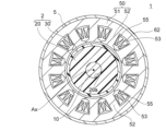
- FIG. 2 is a cross-sectional view of the electric motor taken along line II-II shown in FIG. 1;
- FIG. 2 is a cross-sectional view showing the rotor of Embodiment 1;
- FIG. 2 is a partially cutaway perspective view showing the rotor of Embodiment 1.
- FIG. 1 is a partially cutaway perspective view showing a bearing according to Embodiment 1;
- FIG. 2 is a partially cutaway perspective view showing the outer ring and inner ring of the bearing of Embodiment 1.
- FIG. 2 is a longitudinal sectional view showing an electric motor of Comparative Example 1;
- FIG. 8A is a vertical cross-sectional view (A) showing an electric motor of Comparative Example 2, and (B) is a partially cutaway perspective view showing a rotor of Comparative Example 2; 7 is a graph showing a comparison of bearing voltage ratios between Embodiment 1 and Comparative Example 2.
- FIG. FIG. 10 is a vertical cross-sectional view showing an electric motor of Modification 1;
- FIG. 8 is a partially cutaway perspective view showing a rotor of Modification 1;
- 4 is a graph showing the relationship between the length of the facing portion of the rotor and the bearing voltage ratio in Embodiment 1 and Modification 1.
- FIG. FIG. 10 is a diagram showing a rotor of Modification 2;
- FIG. 6 is a vertical cross-sectional view showing an electric motor according to Embodiment 2;
- FIG. 11 is a vertical cross-sectional view showing an electric motor according to Embodiment 3;
- FIG. 11 is a vertical cross-sectional view showing an electric motor of Comparative Example 3;
- 10 is a graph showing the relationship between the length of the facing portion of the rotor of Comparative Example 3 and the bearing voltage ratio.
- FIG. 11 is a vertical cross-sectional view showing a ventilation fan according to Embodiment 4;
- FIG. 21 is a perspective view showing the ventilation fan shown in FIG. 20;
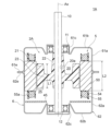
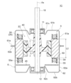
- FIG. 1 is a longitudinal sectional view showing an electric motor 1 according to Embodiment 1.
- FIG. The electric motor 1 is a synchronous motor and is used, for example, in the blower 9 of a ventilation fan (FIG. 20).
- the electric motor 1 includes a rotating shaft 10 , a rotor 2 fixed to the rotating shaft 10 , a stator 5 surrounding the rotor 2 , a housing 6 containing the stator 5 , and bearings 11 and 12 supporting the rotating shaft 10 .
- a central axis Ax of the rotating shaft 10 defines the center of rotation of the rotor 2 .
- a radial direction centered on the central axis Ax is defined as a “radial direction”.
- a circumferential direction centered on the central axis Ax is defined as a “circumferential direction”.
- a cross-sectional view in a plane parallel to the central axis Ax is a vertical cross-sectional view, and a cross-sectional view in a plane orthogonal to the central axis Ax is a transverse cross-sectional view.
- the housing 6 has a first frame 61 and a second frame 62 in the axial direction. Both the first frame 61 and the second frame 62 are made of metal, more specifically steel plate.
- the first frame 61 has a cylindrical peripheral wall portion 61a centered on the central axis Ax, and a bottom portion 61b formed at one axial end of the peripheral wall portion 61a.
- An annular flange portion 61e is formed at the other axial end of the peripheral wall portion 61a.
- the second frame 62 has a cylindrical peripheral wall portion 62a centered on the central axis Ax and a bottom portion 62b formed at one axial end of the peripheral wall portion 62a.
- An annular flange portion 62e is formed at the other axial end of the peripheral wall portion 62a.
- the first frame 61 and the second frame 62 are combined so that the flange portions 61e and 62e are butted against each other.
- the flange portions 61e and 62e of the first frame 61 and the second frame 62 are fixed to each other by adhesion, fastening or welding.
- the housing 6 consisting of the first frame 61 and the second frame 62 is grounded.
- a bearing holding portion 61c for holding the bearing 11 is formed on the bottom portion 61b of the first frame 61. As shown in FIG.
- the bearing holding portion 61c is formed, for example, by deforming the central portion of the bottom portion 61b into a tubular shape. The bearing 11 is fitted in the bearing holding portion 61c.
- a bearing holding portion 62c for holding the bearing 12 is formed on the bottom portion 62b of the second frame 62. As shown in FIG.
- the bearing holding portion 62c is formed, for example, by deforming the central portion of the bottom portion 62b into a tubular shape.
- the bearing 12 is fitted in the bearing holding portion 62c.
- the bearings 11, 12 rotatably support the rotary shaft 10.
- the bearing 11 is positioned in the axial direction by contact between the rotor 2 and an inner cylindrical portion 22 of a ferrite bond magnet 20, which will be described later.
- the bearing 12 is axially positioned by an e-ring or the like attached to the rotating shaft 10 .
- the rotary shaft 10 protrudes to the outside from an opening formed in the bottom portion 61b of the first frame 61.
- a blade portion 90 (FIG. 20), for example, is attached to the tip portion of the rotating shaft 10 . Therefore, the projecting side of the rotary shaft 10 is called the load side, and the opposite side is called the anti-load side.
- FIG. 2 is a cross-sectional view of electric motor 1 taken along line II-II shown in FIG.
- the stator 5 has a stator core 50 and coils 55 wound around the stator core 50 .
- Stator core 50 has an annular yoke 51 centered on central axis Ax and a plurality of teeth 52 extending radially inward from yoke 51 .
- the outer peripheral surface of the yoke 51 is fitted to the inner peripheral surface of the housing 6 .
- the teeth 52 are arranged at regular intervals in the circumferential direction. Tip portions of the teeth 52 face the outer peripheral surface of the rotor 2 via an air gap. Although the number of teeth 52 is twelve here, it is not limited to twelve. Slots 53 are formed between adjacent teeth 52 .
- the coil 55 is composed of magnet wire, for example.
- the coil 55 is wound around the tooth 52 via the insulating portion 54 ( FIG. 1 ) and accommodated in the slot 53 .
- a portion of the coil 55 that does not fit in the slot 53 and extends on the end face in the axial direction of the stator core 50 is referred to as a coil end 55a (FIG. 1).
- the insulating portion 54 shown in FIG. 1 is made of resin such as PPS (polyphenylene sulfide), PET (polyethylene terephthalate), or PBT (polybutylene terephthalate). Note that the insulating portion 54 is omitted in FIG.
- a circuit board 45 is arranged on the anti-load side of the stator 5 .
- the circuit board 45 is supported by pins (not shown) fixed to the insulating portion 54 .
- a drive circuit such as an inverter for rotating the electric motor 1 is mounted on the circuit board 45 .
- the circuit board 45 may be arranged outside the housing 6 .
- FIG. 3 is a cross-sectional view showing the rotor 2.
- the rotor 2 includes a ferrite bonded magnet 20 as a first permanent magnet fixed to a rotating shaft 10 (FIG. 2) and a rare earth bonded magnet 30 as a second permanent magnet provided on the outer peripheral side of the ferrite bonded magnet 20. and Ferrite bond magnet 20 and rare earth bond magnet 30 are molded integrally with rotary shaft 10 .
- the ferrite bond magnet 20 contains magnetic powder of a ferrite magnet and resin.
- the resin contained in the ferrite bond magnet 20 is, for example, polyamide (nylon), but may be PPS (polyphenylene sulfide) or the like.
- the magnetic powder of the ferrite magnet has insulating properties, and the resin surrounding the magnetic powder also has insulating properties, so the ferrite bond magnet 20 as a whole has insulating properties.
- the ferrite bond magnet 20 is oriented to have four S poles and four N poles alternately in the circumferential direction.
- the ferrite bond magnet 20 has eight poles. However, the number of poles of the ferrite bond magnet 20 is not limited to eight, and may be two or more.
- the rare earth bonded magnet 30 contains rare earth magnet magnetic powder and resin.
- Rare earth magnets are, for example, neodymium magnets containing neodymium (Nd), iron (Fe), and boron (B), or samarium iron-nitrogen magnets containing samarium (Sm), iron (Fe), and nitrogen (N). .
- the resin contained in the rare earth bonded magnet is, for example, polyamide (nylon), but may also be PPS or the like.
- the magnetic powder of the rare earth magnet has electrical conductivity
- the resin surrounding the magnetic powder has insulating properties, so the rare earth bonded magnet 30 as a whole has insulating properties.
- the rare earth bonded magnet 30 is oriented so as to have four S poles and four N poles alternately in the circumferential direction. That is, the rare earth bonded magnet 30 has eight poles. However, the number of poles of the rare-earth bonded magnet 30 is not limited to eight, and may be the same as the number of poles of the ferrite bonded magnet 20 .
- the ferrite bonded magnet 20 and the rare earth bonded magnet 30 have different magnetic forces. Specifically, the magnetic force of rare earth bonded magnet 30 is higher than the magnetic force of ferrite bonded magnet 20 .
- FIG. 4 is a partially cutaway perspective view showing the rotor 2.
- the ferrite bond magnet 20 includes an annular portion 21 centered on the central axis Ax, an inner cylindrical portion 22 fixed to the rotating shaft 10 (FIG. 1), and a connection portion connecting the annular portion 21 and the inner cylindrical portion 22. 23.
- the annular portion 21 has an axial length L1
- the inner tubular portion 22 has an axial length L3
- the connecting portion has an axial length L4.
- the lengths L1 and L3 have a relationship of L1 ⁇ L3
- the inner cylindrical portion 22 protrudes from the annular portion 21 to one side in the axial direction (here, the bearing 11 side) so that the bearing 11 is positioned as the shaft. positioned in the direction
- the bearing 11 when the bearing 11 is positioned by an e-ring or the like, it is possible to set L1 ⁇ L3 so that the inner cylindrical portion 22 does not protrude from the annular portion 21 .
- the lengths L1 and L4 have a relationship of L1>L4, and the connecting portion 23 is accommodated inside the annular portion 21 in the axial direction.
- a rare earth bonded magnet 30 is fixed to the outer peripheral surface 20 b of the ferrite bonded magnet 20 , that is, the outer peripheral surface of the annular portion 21 .
- Rotating shaft 10 is fixed to inner peripheral surface 20 a of ferrite bond magnet 20 , that is, to the inner peripheral surface of inner cylindrical portion 22 .
- the rare earth bonded magnet 30 is formed in an annular shape as a whole.
- An inner peripheral surface 30 a of rare earth bonded magnet 30 is fixed to an outer peripheral surface 20 b of ferrite bonded magnet 20 .
- An outer peripheral surface 30b of rare earth bonded magnet 30 faces teeth 52 (FIG. 2) of stator 5 via an air gap.
- the axial length L1 of the rare earth bonded magnet 30 is the same as the axial length L1 of the facing portion 25 of the ferrite bonded magnet 20 .
- the annular portion 21 of the ferrite bonded magnet 20 and the rare earth bonded magnet 30 are collectively referred to as a facing portion 25 .
- the facing portion 25 faces the stator core 50 via an air gap in the radial direction.
- the axial length of the facing portion 25 is the above length L1.
- annular portion 21 and the rare earth bonded magnet 30 that constitute the facing portion 25 are also referred to as the first magnet portion, and the rare earth bonded magnet 30 is also referred to as the second magnet portion.
- the inner cylindrical portion 22 and the connecting portion 23 of the ferrite bond magnet 20 form a connecting portion located between the facing portion 25 and the rotating shaft 10 .
- the ferrite bond magnet 20 and the rare earth bond magnet 30 are molded integrally with the rotating shaft 10 by insert molding using an injection molding machine.
- the rotating shaft 10 is inserted into the first mold, and the ferrite bond magnet 20 is molded integrally with the rotating shaft 10 by filling the molten ferrite bond magnet material therein.
- the bonded ferrite magnet 20 is oriented to have the magnetic poles shown in FIG.
- rotating shaft 10 and ferrite bond magnet 20 are placed in a second mold, and rare earth bond magnet 30 is formed on outer peripheral surface 20b of ferrite bond magnet 20 by filling the mold with molten rare earth bond magnet material. do.
- the bonded rare earth magnet 30 is oriented to have the magnetic poles shown in FIG.
- the rotating shaft 10 Since the rotating shaft 10, the ferrite bond magnet 20, and the rare earth bond magnet 30 are integrally molded, they are strongly integrated and the manufacturing cost is reduced.
- FIG. 5 is a partially cutaway perspective view showing the bearing 11.
- the bearing 11 has an inner ring 11a fixed to the rotating shaft 10, an outer ring 11b fixed to the housing 6, and a plurality of rolling elements 11c provided between the inner ring 11a and the outer ring 11b.
- the rolling bodies 11c are, for example, balls. All of the inner ring 11a, the outer ring 11b and the rolling elements 11c are made of metal. Shield plates 11d are provided on both axial sides of the inner ring 11a and the outer ring 11b.
- FIG. 6 is a partially cutaway perspective view showing the inner ring 11a and the outer ring 11b of the bearing 11.
- a raceway surface 11e for guiding the rolling elements 11c is formed along the outer circumference of the inner ring 11a.
- a raceway surface 11f for guiding the rolling elements 11c is formed along the inner circumference of the outer ring 11b.
- Grease is applied between the raceway surfaces 11e, 11f and the rolling elements 11c for lubrication.
- a retainer (not shown) is arranged between the inner ring 11a and the outer ring 11b to maintain a constant circumferential interval between the rolling elements 11c.
- FIGS. 5 and 6 show the configuration of the load side bearing 11
- the anti-load side bearing 12 (FIG. 1) has the same configuration.
- the housing 6 corresponds to a conducting member that conducts the outer rings 11 b and 12 b of the bearings 11 and 12 and the stator core 50 .
- FIG. 7 is a diagram showing an electric motor 1E of Comparative Example 1. As shown in FIG. The rotor 2E of Comparative Example 1 is entirely composed of ferrite bond magnets 20 and does not have rare earth bond magnets.
- a ferrite bond magnet 20 has an annular portion 21, an inner cylinder portion 22, and a connection portion 23, as in the first embodiment.
- Annular portion 21 of ferrite bond magnet 20 constitutes facing portion 25 facing stator core 50 .
- the axial length L1 of the facing portion 25 is longer than the axial length L2 of the stator core 50 (L1>L2).
- the ferrite bond magnet 20 contains the magnetic powder of the ferrite magnet and a resin such as polyamide. Although the dielectric constant of polyamide is approximately 3 to 4, the ferrite bond magnet 20 has a dielectric constant of 40 to 200 because it contains magnetic powder.
- the inner ring 11a rotates together with the rotating shaft 10, and the rolling elements 11c also rotate.
- a thin film of grease is formed between the inner ring 11a and the rolling elements 11c and between the outer ring 11b and the rolling elements 11c.
- the inner ring 11a, the outer ring 11b and the rolling elements 11c are electrically insulated.
- the housing 6 to which the outer ring 11b of the bearing 11 is fixed is grounded, but the rotating shaft 10 to which the inner ring 11a is fixed is not grounded.
- the potential of the rotating shaft 10 causes a potential difference between the inner ring 11a and the outer ring 11b. When this potential difference exceeds the dielectric breakdown voltage of the grease thin film, an electric discharge occurs between the inner ring 11a and the outer ring 11b.
- a phenomenon in which the raceway surfaces 11e and 11f of the inner ring 11a and the outer ring 11b become uneven due to the energy of electric discharge is called electrolytic corrosion.
- the raceway surfaces 11e and 11f are uneven, vibration and noise are generated when the rolling elements 11c run on the raceway surfaces 11e and 11f.
- the load-side bearing 11 has been described here, the same is true for the anti-load-side bearing 12 (FIG. 1).
- the potentials of the stator core 50 and the outer rings 11b, 12b that are in contact with the housing 6 are at the ground potential (GND).
- GND ground potential
- electric power is supplied to the coil 55 wound around the stator core 50 via the insulating portion 54, a potential difference is generated between the coil 55 and the stator core 50 and the like. As a result, a potential distribution is generated in the internal space of the electric motor 1E, and a potential of the rotary shaft 10 is generated.
- the potential of the rotating shaft 10 is determined by the capacitance between the stator core 50 and the rotating shaft 10, the capacitance between the coil end 55a and the rotating shaft 10, the inner rings 11a and 12a and the outer rings 11b and 12b of the bearings 11 and 12. depends on the capacitance between
- Patent Document 1 discloses that a plurality of axially long conductive layers are arranged in the circumferential direction inside the coil end in the radial direction (see paragraph 0020 of Patent Document 1).
- the conductive layer is electrically connected to the stator core, it would be possible to reduce the potential of the shaft by an effect like a shield.
- the number of parts increases, which increases the manufacturing cost, and there is a possibility that the parts (that is, the conductive layer) may come off during operation, or the efficiency may be lowered due to eddy currents generated on the surface of the parts.
- the axial length L1 of the facing portion 25 of the rotor 2 (that is, the annular portion 21 of the ferrite bonded magnet 20 and the rare earth bonded magnet 30) is equal to the stator core 50 has an axial length L2 or less (L1 ⁇ L2).
- the facing portion 25 of the rotor 2 does not protrude from the stator core 50 in the axial direction.
- the coil ends 55a of the stator 5 do not face the facing portion 25 of the rotor in the radial direction.
- only the inner cylindrical portion 22 of the ferrite bond magnet 20 is located between the coil end 55a and the rotating shaft 10 in the radial direction and has a high dielectric constant.
- the volume of the inner tubular portion 22 is sufficiently smaller than that of the facing portion 25 .
- the potential of the outer rings 11b and 12b is at the ground potential, the potential difference between the inner rings 11a and 12a and the outer rings 11b and 12b is reduced by lowering the potential of the rotating shaft 10 in contact with the inner rings 11a and 12a. It is possible to suppress the occurrence of eclipse.
- the length L1 of the facing portion 25 of the rotor 2 equal to or less than the length L2 of the stator core 50, the effect of suppressing the occurrence of electrolytic corrosion of the bearings 11 and 12 can be obtained.
- FIG. 8(A) is a longitudinal sectional view showing the electric motor 1F of Comparative Example 2.
- FIG. A rotor 2 ⁇ /b>F of an electric motor 1 ⁇ /b>F of Comparative Example 2 has an annular ferrite bond magnet 24 and a conductive support 46 connecting the rotating shaft 10 and the ferrite bond magnet 24 .
- the ferrite bonded magnet 24 of Comparative Example 2 does not have the inner tubular portion 22 and the connecting portion 23 unlike the ferrite bonded magnet 20 of the first embodiment.
- the ferrite bond magnet 24 constitutes a facing portion 25 as a whole.
- the axial length L1 of the facing portion 25 of the rotor 2F is equal to or less than the axial length L2 of the stator core 50 .
- FIG. 8(B) is a perspective view showing the rotor 2F of Comparative Example 2.
- the conductive support 46 is formed by laminating circular magnetic steel sheets in the axial direction.
- the rotating shaft 10 is fixed to the inner peripheral surface 46 a of the conductive support 46
- the ferrite bond magnet 24 is fixed to the outer peripheral surface 46 b of the conductive support 46 .
- Comparative Example 2 since the conductive support 46 is interposed between the stator core 50 and the rotating shaft 10, the capacitance between the stator core 50 and the rotating shaft 10 is equal to the distance between the stator core 50 and the rotating shaft 10. As if it were narrowed, it would be widened. Therefore, in the electric motor 1F of Comparative Example 2, it is difficult to obtain the effect of reducing the bearing voltage.
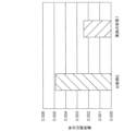
- FIG. 9 is a graph showing a comparison of bearing voltage ratios between the electric motor 1 of Embodiment 1 and the electric motor 1F of Comparative Example 2.
- the bearing voltage ratio on the vertical axis is the ratio of the bearing voltage to the voltage applied to the coil 55 .
- the axial length L1 of the ferrite bond magnet 24 is set to 40 mm, which is the same as the axial length L2 of the stator core 50 . Since the inner rings 11a and 12a of the bearings 11 and 12 are electrically connected through the shaft 10, and the outer rings 11b and 12b are electrically connected through the housing 6, the bearing voltage ratios of the bearings 11 and 12 are the same. .
- the effect of reducing the bearing voltage is smaller than that of the electric motor 1 of the first embodiment. This is because the conductive support 46 is interposed between the stator 5 and the rotating shaft 10, as described above.
- the inner cylindrical portion 22 and the connecting portion 23 of the ferrite bond magnet 20 are interposed between the facing portion 25 of the rotor 2 and the rotating shaft 10, and these have insulating properties. Therefore, the effect of reducing the bearing voltage can be exhibited.
- electric motor 1 of Embodiment 1 has rotating shaft 10 supported by bearings 11 and 12, rotor 2 fixed to rotating shaft 10, and stator core 50 and coil 55 surrounding rotor 2.
- a stator 5 is provided.
- the rotor 2 includes a facing portion 25 that is formed of a bond magnet and faces the stator core 50 in the radial direction, and an insulating connecting portion that connects the facing portion 25 and the rotating shaft 10 (that is, the inner cylindrical portion 22 and the connecting portion 23). and
- the axial length L1 of the facing portion 25 is equal to or less than the axial length L2 of the stator core 50 .
- the high dielectric constant portion located between the coil end 55a and the rotating shaft 10 is reduced, thereby reducing the electrostatic capacitance between the coil end 55a and the rotating shaft 10. , the potential of the rotating shaft 10 can be lowered. As a result, the bearing voltage can be reduced to suppress the occurrence of electrolytic corrosion, and the vibration and noise of the electric motor 1 can be reduced.
- the opposing portion 25 of the rotor 2 has the annular portion 21 of the ferrite bonded magnet 20 and the rare earth bonded magnet 30, a high magnetic force can be generated even if the length L1 of the opposing portion 25 is shortened.
- the rare earth bonded magnet 30 is provided so as to cover the annular portion 21 of the ferrite bonded magnet 20 from the outside in the radial direction, a particularly high magnetic force can be generated.
- the ferrite bonded magnet 20 and the rare earth bonded magnet 30 are molded integrally with the rotating shaft 10, the ferrite bonded magnet 20, the rare earth bonded magnet 30 and the rotating shaft 10 can be firmly integrated, and the manufacturing process is simplified. Cost can be reduced.
- the rotor 2 of Embodiment 1 is composed of ferrite bonded magnets and rare earth bonded magnets, the rotor 2 is not limited to a combination of these, and may be composed of two types of bonded magnets.
- FIG. 10 is a diagram showing an electric motor 1A of Modification 1.
- FIG. 11 is a perspective view showing the rotor 2A of the electric motor 1A of Modification 1.
- FIG. 10 and 11 in the electric motor 1A of Modification 1, the rotor 2A is composed of the ferrite bond magnets 20 and does not have the rare earth bond magnets 30.
- FIG. 10 is a diagram showing an electric motor 1A of Modification 1.
- FIG. 11 is a perspective view showing the rotor 2A of the electric motor 1A of Modification 1.
- FIG. 10 and 11 in the electric motor 1A of Modification 1, the rotor 2A is composed of
- a ferrite bond magnet 20 has an annular portion 21, an inner cylinder portion 22, and a connection portion 23, as in the first embodiment.
- Annular portion 21 of ferrite bond magnet 20 constitutes facing portion 25 .
- the axial length L1 of the facing portion 25 is equal to or less than the axial length L2 of the stator core 50 (L1 ⁇ L2).
- the facing portion 25 does not protrude from the stator core 50 in the axial direction.
- the ferrite bond magnet 20 is molded integrally with the rotating shaft 10 by insert molding using an injection molding machine. By applying a polar anisotropic magnetic field during molding, the bonded ferrite magnet 20 is oriented to have the magnetic poles shown in FIG.
- the magnetic force of ferrite bonded magnets is lower than that of rare earth bonded magnets. Therefore, the magnetic force of rotor 2A of Modification 1, which does not have rare earth bonded magnets, is lower than the magnetic force of rotor 2 of Embodiment 1, which has rare earth bonded magnets.
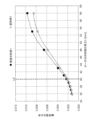
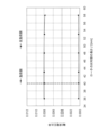
- FIG. 12 is a graph showing the relationship between the bearing voltage ratio and the length L1 of the facing portion 25 of the rotors 2 and 2A of Embodiment 1 and Modification 1, obtained by electric field analysis.
- the horizontal axis indicates the length L1 of the facing portion 25 .
- the bearing voltage ratio on the vertical axis is the ratio of the bearing voltage to the voltage applied to the coil 55 .
- the bearing voltage ratios of the bearings 11 and 12 are the same.
- the axial length L2 of the stator core 50 is fixed at 40 mm, and the axial length L1 of the facing portion 25 of the rotors 2, 2A is varied from 36 mm to 58 mm.
- the bearing voltage increases as the length L1 of the facing portion 25 of the rotors 2 and 2A increases. Further, in a region where the length L1 of the facing portion 25 is longer than the length L2 of the stator core 50, that is, in a region where L1>L2, the bearing voltage of the first embodiment is higher than the bearing voltage of the first modification.
- the length L1 of the facing portion 25 is set to be equal to or less than the length L2 of the stator core 50, thereby reducing the bearing voltage and preventing electrolytic corrosion. It can be seen that the occurrence of can be suppressed.
- the rotor 2 of the first embodiment is composed of the ferrite bonded magnet 20 and the rare earth bonded magnet 30, and the rotor 2A of the modified example 1 is composed of the ferrite bonded magnet 20. It may be composed only of other types of bonded magnets. However, if the rotor is composed only of rare earth bonded magnets, the bearing voltage tends to be too high, so it is desirable to include ferrite bonded magnets.
- FIG. 13 is a cross-sectional view showing the rotor 2 of Modification 2.
- annular rare earth bonded magnet 30 covers outer peripheral surface 20 b of ferrite bonded magnet 20 .
- a plurality of rare earth bonded magnets 31 are arranged along the outer peripheral surface 20 b of the ferrite bonded magnet 20 .
- the rare earth bonded magnets 31 are arranged at regular intervals in the circumferential direction.
- the number of rare earth bonded magnets 31 is the same as the number of poles of the rotor 2B. Circumferentially adjacent rare earth bonded magnets 31 are magnetized with opposite polarities.
- a plurality of recesses 20c in which the rare earth bonded magnets 31 are arranged are formed on the outer peripheral surface 20b of the ferrite bonded magnet 20, that is, the outer peripheral surface of the annular portion 21 (FIG. 4).
- a facing portion 25 is formed by the annular portion 21 of the ferrite bonded magnet 20 and the rare earth bonded magnet 31 .
- Rotor 2B of Modification 2 has ferrite bond magnet 20 and rare earth bond magnet 31. Therefore, similar to Embodiment 1, even if length L1 in the axial direction of opposing portion 25 of rotor 2B is shortened, a high magnetic force can be obtained. can be generated.
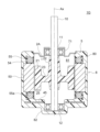
- FIG. 14 is a longitudinal sectional view showing electric motor 1C of the second embodiment.
- Rotor 2 ⁇ /b>C of Embodiment 2 includes annular ferrite bond magnet 24 and resin portion 40 as a connecting portion that connects rotating shaft 10 and ferrite bond magnet 24 .
- the ferrite bond magnet 24 of the second embodiment does not have the inner tubular portion 22 and the connecting portion 23 like the ferrite bond magnet 20 of the first embodiment.
- the ferrite bond magnet 24 constitutes a facing portion 25 as a whole.
- the axial length L1 of the facing portion 25 of the rotor 2C is equal to or less than the axial length L2 of the stator core 50 .
- FIG. 15 is a perspective view showing the rotor 2C.
- the resin portion 40 connects an inner cylindrical portion 42 fixed to the rotating shaft 10 ( FIG. 14 ), an annular portion 41 surrounding the inner cylindrical portion 42 from the radially outer side, and the annular portion 41 and the inner cylindrical portion 42 . and a connecting portion 43 .
- Ferrite bond magnet 24 is fixed to annular portion 41 .
- the resin part 40 is made of resin such as PBT, polyamide (nylon), or liquid crystal polymer (LCP), and is an insulator.
- the dielectric constant of the resin forming the resin portion 40 is approximately 4, which is sufficiently lower than the dielectric constant of the ferrite bond magnet 24 .
- the capacitance between the coil end 55a and the rotating shaft 10 can be reduced.
- the bearing voltage of bearings 11 and 12 can be reduced, and the occurrence of electrolytic corrosion can be suppressed.
- FIG. 16 is a graph showing the relationship between the axial length L1 of the ferrite bond magnet 24 of the rotor 2C of Embodiment 2 and the bearing voltage ratio obtained by electric field analysis.
- the horizontal axis indicates the length L1 of the facing portion 25 .
- the bearing voltage ratio on the vertical axis is the ratio of the bearing voltage to the voltage applied to the coil 55 .
- the bearing voltage ratios of the bearings 11 and 12 are the same.
- the bearing voltage is particularly low when the length L1 of the ferrite bond magnet 24 is equal to or less than the length L2 of the stator core 50 (L1 ⁇ L2). 12 and 16, it can be seen that the bearing voltage in the second embodiment is lower than that in the first embodiment. This is because the low dielectric constant resin portion 40 is interposed between the ferrite bond magnet 24 and the shaft 10 .
- a rare earth bonded magnet 30 may be provided on the outer peripheral side of the ferrite bonded magnet 24 . By providing the rare-earth bonded magnet 30, it is possible to increase the magnetic force of the rotor 2C.
- the electric motor 1C of the second embodiment is configured in the same manner as the electric motor 1 of the first embodiment except for the points described above.
- the ferrite bond magnet 24 is connected to the rotary shaft 10 via the resin portion 40 having a lower dielectric constant than the ferrite bond magnet 24. Therefore, the coil end 55a and the rotary shaft 10 can be reduced. Thereby, the bearing voltage of the bearings 11 and 12 can be reduced, and the occurrence of electrolytic corrosion can be suppressed.
- FIG. 17 is a longitudinal sectional view showing electric motor 1D of the third embodiment.
- stator 5 is held by metal housing 6, but in electric motor 1D of Embodiment 3, stator 5 is held by molded resin portion 80.
- FIG. 17 is a longitudinal sectional view showing electric motor 1D of the third embodiment.
- stator 5 is held by metal housing 6, but in electric motor 1D of Embodiment 3, stator 5 is held by molded resin portion 80.
- a mold resin portion 80 as a resin portion is formed of BMC (bulk molding compound) containing unsaturated polyester.
- the molded resin portion 80 is formed so as to cover the stator 5 from the radially outer side and the anti-load side.
- the molded resin portion 80 has an opening 81 on the load side and a bearing holding portion 82 on the anti-load side.
- the rotor 2A is inserted into the stator 5 through the opening 81.
- the stator 5 and the molded resin portion 80 constitute the molded stator 8 .
- the load-side bearing 11 is held by a metal bracket 71 attached to the opening 81 of the molded resin portion 80 .
- the bracket 71 includes a cylindrical portion 71a that supports the bearing 11, a plate-like portion 71b that extends radially outward from the cylindrical portion 71a, and a fitting portion 71c that fits into a stepped portion around the opening 81. have A tubular portion 71 a of the bracket 71 contacts the outer ring 11 b of the bearing 11 .
- the bracket 71 is also called a conductive member or a first conductive member.
- the anti-load side bearing 12 is held by a conductive cap 72 .
- the cap 72 has, for example, a bottomed cylindrical shape, and is covered from the radially outer side by the bearing holding portion 82 of the mold resin portion 80 .
- Cap 72 contacts outer ring 12 b of bearing 12 .
- Cap 72 is also referred to as a conductive member or a second conductive member.
- the housing 6 is grounded, but in Embodiment 3, the mold resin portion 80 is insulative and cannot be grounded. Therefore, in Embodiment 3, the bracket 71 and the cap 72 are grounded.
- the conductive pin 85 provided on the bracket 71 and the conductive pin 56 provided on the load side of the stator core 50 are electrically connected by the lead wire 58 .
- the conductive pin 86 provided on the cap 72 and the conductive pin 57 provided on the anti-load side of the stator core 50 are electrically connected by the lead wire 59 .
- a drive circuit such as an inverter is mounted on the circuit board 45, and is grounded to the ground outside the electric motor 1D via a lead wire (not shown). Therefore, the outer ring 11 b of the bearing 11 is grounded via the bracket 71 , the lead wire 58 and the circuit board 45 . Also, the outer ring 12 b of the bearing 12 is grounded via the cap 72 , the lead wire 59 and the circuit board 45 .
- the electric motor 1D has the rotor 2A described in Modification 1.
- the length L1 of the annular portion 21 of the rotor 2A is less than or equal to the length L2 of the stator core 50.
- the rotor 2 of Embodiment 1, the rotor 2B of Modification 2, or the rotor 2C of Embodiment 2 may be used instead of rotor 2A.
- the electric motor 1D of the third embodiment is configured in the same manner as the electric motor 1 of the first embodiment except for the points described above.
- FIG. 18 is a longitudinal sectional view showing an electric motor 1G of Comparative Example 3.
- the load-side bearing 11 is held by a metal bracket 71, but the bracket 71 is not grounded.
- the metal cap 72 that holds the bearing 12 on the anti-load side is not provided. That is, none of the outer rings 11b, 12b of the bearings 11, 12 are grounded.
- the outer ring 12b In the bearing 12 on the anti-load side, the outer ring 12b is close to the circuit board 45, and the circuit board 45 is grounded by a lead wire, so the potential of the outer ring 12b is close to the ground potential.
- the inner ring 12a since the inner ring 12a is in contact with the rotating shaft 10 and electrostatic capacitance exists between the rotating shaft 10 and the coil end 55a, the potential of the inner ring 12a tends to be higher than the ground potential. Therefore, a potential difference is likely to occur between the inner ring 12a and the outer ring 12b.
- the inner ring 11a is in contact with the rotating shaft 10, and electrostatic capacitance exists between the rotating shaft 10 and the coil end 55a, so the potential of the inner ring 11a tends to increase.
- the bearing 11 is separated from the circuit board 45 and the potential of the outer ring 11b is not at the ground potential, the potential difference between the inner ring 11a and the outer ring 11b is unlikely to occur.
- FIG. 19 is a graph showing the relationship between the length L1 of the annular portion 21 of the rotor 2A and the bearing voltage in each of the bearings 11 and 12 in the electric motor 1G of Comparative Example 3. As shown in FIG. 19, the bearing voltage of bearing 12 on the anti-load side is greater than the bearing voltage of bearing 11 on the load side.
- Embodiment 3 As shown in FIG. grounded. That is, the potential of the outer rings 11b, 12b of the bearings 11, 12 becomes the ground potential.
- the axial length L1 of the facing portion 25 of the rotor 2A is set to be equal to or less than the axial length L2 of the stator core 50.
- stator core 50 is held by molded resin portion 80, outer ring 11b of bearing 11 is grounded via bracket 71 and lead wire 58, and outer ring 12b of bearing 12 is grounded via bracket 71 and lead wire 58. It is grounded via the cap 72 and the lead wire 59, and the length L1 of the annular portion 21 of the rotor 2A is less than or equal to the length L2 of the stator core 50. Therefore, the electrostatic capacitance between the coil end 55a and the rotating shaft 10 can be reduced, the bearing voltage of the bearings 11 and 12 can be reduced, and the occurrence of electrolytic corrosion can be suppressed.
- Embodiment 4 relates to a fan 9 to which the electric motors of the embodiments and modifications described above are applied, and a ventilator 100 having the fan 9 .
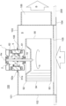
- FIG. 20 is a cross-sectional view showing the ventilation fan 100.
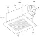
- FIG. FIG. 21 is a perspective view showing the ventilation fan 100.
- the ventilating fan 100 is arranged on the indoor ceiling and exhausts indoor air to the outside through an exhaust duct.
- the ventilation fan 100 is also called a duct ventilation fan.
- the ventilation fan 100 includes a blower 9 and a housing 101 to which the blower 9 is attached.
- Blower 9 has electric motor 1 described in the first embodiment and blade portion 90 attached to rotating shaft 10 of electric motor 1 . It should be noted that the electric motor described in the second and third embodiments or each modification may be used instead of the electric motor 1 described in the first embodiment.
- the blade portion 90 is also called a sirocco fan, and has a plurality of blades 94 arranged in the circumferential direction between a main plate 92 and a side plate 93 facing each other in the axial direction.
- the main plate 92 is fixed to the rotating shaft 10 .
- the rotation of the blade portion 90 generates a flow of air radially outward from the central axis Ax.
- the housing 101 is a cuboid container made of steel or resin.
- the housing 101 has a top plate 103 and a bottom plate 104 facing each other in the axial direction, and a side wall 102 formed therebetween.
- the top plate 103 has an opening 108 in which the electric motor 1 is mounted.
- the electric motor 1 is mounted in the opening 108 so that the first frame 61 side is accommodated inside the housing 101 , and the flanges 61 e and 62 e are fixed around the opening 108 .
- the outer peripheral edge of the bottom plate 104 is fixed to the bottom surface of the ceiling plate 200 .
- the bottom plate 104 is formed with a grill 105 for sucking air from the room as indicated by an arrow A.
- a ventilation duct 106 for discharging air to the outside of the housing 101 is attached to the side wall 102 of the housing 101 .
- the ventilation duct 106 is connected to an exhaust duct (not shown) leading to the outdoors.
- the ventilation fan 100 Since the ventilation fan 100 is installed on the indoor ceiling, vibration and noise are likely to be transmitted indoors.
- electric motor 1 described in the first embodiment as a drive source for ventilating fan 100, vibration and noise caused by electrolytic corrosion of bearings 11 and 12 can be reduced. Therefore, vibration and noise transmitted indoors can be reduced, and quietness can be improved.
- the life of the ventilation fan 100 can be lengthened and the reliability can be improved.
- the electric motor described in the second or third embodiment or each modified example is used instead of the electric motor 1 described in the first embodiment.
- a ventilation fan using a sirocco fan has been described, but the form of the blade portion is not limited to a sirocco fan, and may be a propeller fan, a cross-flow fan, or the like.
- blower having the electric motor described in each embodiment and each modified example is not limited to ventilation fans, and may be used for range hoods, bathroom dryers, fans, dehumidifiers, air conditioners, and the like.
Landscapes
- Engineering & Computer Science (AREA)
- Power Engineering (AREA)
- Motor Or Generator Frames (AREA)
Priority Applications (4)
| Application Number | Priority Date | Filing Date | Title |
|---|---|---|---|
| PCT/JP2021/035628 WO2023053199A1 (ja) | 2021-09-28 | 2021-09-28 | 電動機、送風機および換気扇 |
| JP2023550785A JP7665035B2 (ja) | 2021-09-28 | 2021-09-28 | 電動機、送風機および換気扇 |
| CN202180102516.5A CN117957753A (zh) | 2021-09-28 | 2021-09-28 | 电动机、送风机以及换气扇 |
| US18/690,790 US20240405630A1 (en) | 2021-09-28 | 2021-09-28 | Motor, fan, and ventilation fan |
Applications Claiming Priority (1)
| Application Number | Priority Date | Filing Date | Title |
|---|---|---|---|
| PCT/JP2021/035628 WO2023053199A1 (ja) | 2021-09-28 | 2021-09-28 | 電動機、送風機および換気扇 |
Publications (1)
| Publication Number | Publication Date |
|---|---|
| WO2023053199A1 true WO2023053199A1 (ja) | 2023-04-06 |
Family
ID=85781509
Family Applications (1)
| Application Number | Title | Priority Date | Filing Date |
|---|---|---|---|
| PCT/JP2021/035628 Ceased WO2023053199A1 (ja) | 2021-09-28 | 2021-09-28 | 電動機、送風機および換気扇 |
Country Status (4)
| Country | Link |
|---|---|
| US (1) | US20240405630A1 (https=) |
| JP (1) | JP7665035B2 (https=) |
| CN (1) | CN117957753A (https=) |
| WO (1) | WO2023053199A1 (https=) |
Cited By (2)
| Publication number | Priority date | Publication date | Assignee | Title |
|---|---|---|---|---|
| JP7531751B1 (ja) * | 2023-11-29 | 2024-08-09 | 三菱電機株式会社 | ロータおよび永久磁石モータ |
| WO2025197060A1 (ja) * | 2024-03-22 | 2025-09-25 | 三菱電機株式会社 | 電動機、及び送風装置 |
Citations (6)
| Publication number | Priority date | Publication date | Assignee | Title |
|---|---|---|---|---|
| JP2004229429A (ja) * | 2003-01-23 | 2004-08-12 | Nidec Shibaura Corp | モールドモータ |
| JP2011030423A (ja) * | 2010-11-10 | 2011-02-10 | Mitsubishi Electric Corp | 同期電動機、換気扇、冷媒圧縮機、送風機、液体用ポンプ、空気調和機、及び冷蔵庫 |
| JP5076311B2 (ja) * | 2005-12-07 | 2012-11-21 | パナソニック株式会社 | ブラシレスモータ |
| CN103973043A (zh) * | 2013-01-31 | 2014-08-06 | 台达电子工业股份有限公司 | 马达 |
| JP2015106944A (ja) * | 2013-11-28 | 2015-06-08 | 日本電産テクノモータ株式会社 | モータおよびモータの製造方法 |
| WO2020261420A1 (ja) * | 2019-06-26 | 2020-12-30 | 三菱電機株式会社 | 回転子、電動機、送風機、空気調和機、及び回転子の製造方法 |
Family Cites Families (2)
| Publication number | Priority date | Publication date | Assignee | Title |
|---|---|---|---|---|
| JPH1014159A (ja) * | 1996-06-20 | 1998-01-16 | Matsushita Seiko Co Ltd | 送風機用軸受保護装置 |
| KR20190111113A (ko) * | 2017-03-31 | 2019-10-01 | 니혼 덴산 테크노 모터 가부시키가이샤 | 모터 |
-
2021
- 2021-09-28 WO PCT/JP2021/035628 patent/WO2023053199A1/ja not_active Ceased
- 2021-09-28 CN CN202180102516.5A patent/CN117957753A/zh not_active Withdrawn
- 2021-09-28 JP JP2023550785A patent/JP7665035B2/ja active Active
- 2021-09-28 US US18/690,790 patent/US20240405630A1/en active Pending
Patent Citations (6)
| Publication number | Priority date | Publication date | Assignee | Title |
|---|---|---|---|---|
| JP2004229429A (ja) * | 2003-01-23 | 2004-08-12 | Nidec Shibaura Corp | モールドモータ |
| JP5076311B2 (ja) * | 2005-12-07 | 2012-11-21 | パナソニック株式会社 | ブラシレスモータ |
| JP2011030423A (ja) * | 2010-11-10 | 2011-02-10 | Mitsubishi Electric Corp | 同期電動機、換気扇、冷媒圧縮機、送風機、液体用ポンプ、空気調和機、及び冷蔵庫 |
| CN103973043A (zh) * | 2013-01-31 | 2014-08-06 | 台达电子工业股份有限公司 | 马达 |
| JP2015106944A (ja) * | 2013-11-28 | 2015-06-08 | 日本電産テクノモータ株式会社 | モータおよびモータの製造方法 |
| WO2020261420A1 (ja) * | 2019-06-26 | 2020-12-30 | 三菱電機株式会社 | 回転子、電動機、送風機、空気調和機、及び回転子の製造方法 |
Cited By (3)
| Publication number | Priority date | Publication date | Assignee | Title |
|---|---|---|---|---|
| JP7531751B1 (ja) * | 2023-11-29 | 2024-08-09 | 三菱電機株式会社 | ロータおよび永久磁石モータ |
| WO2025115138A1 (ja) * | 2023-11-29 | 2025-06-05 | 三菱電機株式会社 | ロータおよび永久磁石モータ |
| WO2025197060A1 (ja) * | 2024-03-22 | 2025-09-25 | 三菱電機株式会社 | 電動機、及び送風装置 |
Also Published As
| Publication number | Publication date |
|---|---|
| JP7665035B2 (ja) | 2025-04-18 |
| CN117957753A (zh) | 2024-04-30 |
| JPWO2023053199A1 (https=) | 2023-04-06 |
| US20240405630A1 (en) | 2024-12-05 |
Similar Documents
| Publication | Publication Date | Title |
|---|---|---|
| CN103155368B (zh) | 电动机以及具有该电动机的电气设备 | |
| US11394260B2 (en) | Rotor, motor, fan, and air conditioning apparatus | |
| CN102859845B (zh) | 电动机和具有该电动机的电设备 | |
| CN110971033B (zh) | 马达 | |
| WO2016174790A1 (ja) | 遠心送風機および掃除機 | |
| US7227286B2 (en) | Long life fan motor | |
| JP7486629B2 (ja) | 回転子、電動機、送風機、空気調和装置、及び回転子の製造方法 | |
| JP7665035B2 (ja) | 電動機、送風機および換気扇 | |
| US11852167B2 (en) | Motor and air conditioner using the same | |
| JPWO2020129210A1 (ja) | 回転子、電動機、送風機、空気調和装置および回転子の製造方法 | |
| JP2023054239A (ja) | 電動機、送風機及び空気調和装置 | |
| CN115088163A (zh) | 送风机及空气调节装置 | |
| US12081097B2 (en) | Motor, fan, and air conditioner | |
| US12424889B2 (en) | Rotor, motor using the rotor, and electronic device | |
| JP2016205336A (ja) | 遠心送風機および掃除機 | |
| WO2020129205A1 (ja) | 回転子、電動機、送風機、空気調和装置および回転子の製造方法 | |
| JP2012222841A (ja) | 電動機およびそれを備えた電気機器 | |
| CN118613994A (zh) | 电动机和空调机 | |
| JP2013066252A (ja) | 電動機およびそれを備えた電気機器 | |
| WO2023139739A1 (ja) | 電動機、送風機および空気調和装置 | |
| WO2023148953A1 (ja) | ロータ、電動機、送風機、空気調和装置および電動機の製造方法 | |
| JP2023021030A (ja) | 電動機及びそれを備えた電気機器 | |
| WO2020021990A1 (ja) | 電動機 | |
| WO2020129207A1 (ja) | 回転子、電動機、送風機、空気調和装置および回転子の製造方法 |
Legal Events
| Date | Code | Title | Description |
|---|---|---|---|
| 121 | Ep: the epo has been informed by wipo that ep was designated in this application |
Ref document number: 21959249 Country of ref document: EP Kind code of ref document: A1 |
|
| WWE | Wipo information: entry into national phase |
Ref document number: 2023550785 Country of ref document: JP |
|
| WWE | Wipo information: entry into national phase |
Ref document number: 202180102516.5 Country of ref document: CN |
|
| NENP | Non-entry into the national phase |
Ref country code: DE |
|
| 122 | Ep: pct application non-entry in european phase |
Ref document number: 21959249 Country of ref document: EP Kind code of ref document: A1 |