WO2023048093A1 - Lens barrel, imaging device, and drive device - Google Patents
Lens barrel, imaging device, and drive device Download PDFInfo
- Publication number
- WO2023048093A1 WO2023048093A1 PCT/JP2022/034799 JP2022034799W WO2023048093A1 WO 2023048093 A1 WO2023048093 A1 WO 2023048093A1 JP 2022034799 W JP2022034799 W JP 2022034799W WO 2023048093 A1 WO2023048093 A1 WO 2023048093A1
- Authority
- WO
- WIPO (PCT)
- Prior art keywords
- lead screw
- annular member
- groove
- lens barrel
- lens
- Prior art date
Links
- 238000003384 imaging method Methods 0.000 title claims description 6
- 230000003287 optical effect Effects 0.000 claims description 24
- 238000005096 rolling process Methods 0.000 description 6
- 125000006850 spacer group Chemical group 0.000 description 6
- 238000010586 diagram Methods 0.000 description 4
- 239000000470 constituent Substances 0.000 description 2
- 230000000694 effects Effects 0.000 description 2
- 238000006243 chemical reaction Methods 0.000 description 1
- 230000006835 compression Effects 0.000 description 1
- 238000007906 compression Methods 0.000 description 1
- 230000003111 delayed effect Effects 0.000 description 1
- 230000012447 hatching Effects 0.000 description 1
- 238000012986 modification Methods 0.000 description 1
- 230000004048 modification Effects 0.000 description 1
- 230000002093 peripheral effect Effects 0.000 description 1
Images


Classifications
-
- G—PHYSICS
- G02—OPTICS
- G02B—OPTICAL ELEMENTS, SYSTEMS OR APPARATUS
- G02B7/00—Mountings, adjusting means, or light-tight connections, for optical elements
- G02B7/02—Mountings, adjusting means, or light-tight connections, for optical elements for lenses
- G02B7/04—Mountings, adjusting means, or light-tight connections, for optical elements for lenses with mechanism for focusing or varying magnification
- G02B7/08—Mountings, adjusting means, or light-tight connections, for optical elements for lenses with mechanism for focusing or varying magnification adapted to co-operate with a remote control mechanism
Definitions
- lens barrel Regarding the lens barrel, imaging device, and driving device.
- Patent Document 1 A mechanism for driving a focus lens using a lead screw and a nut engaged with the lead screw has been proposed (for example, Patent Document 1). There is a demand for higher performance of a drive mechanism that drives a focus lens.
- the lens barrel includes a lens holding frame that holds a lens, a drive source, a lead screw formed with a first thread groove and rotationally driven by the drive source, the first an annular member having a groove on its inner circumference that abuts on the thread groove of the lens holding frame, is connected to the lens holding frame, rotatably holds the annular member, and moves in the axial direction of the lead screw as the lead screw rotates. and a biasing portion that biases the annular member toward the lead screw in a direction orthogonal to the axial direction of the lead screw.
- the lens barrel includes a lens holding frame that holds a lens, a drive source, a lead screw formed with a thread groove and rotationally driven by the drive source, and a contact with the thread groove.
- a rotating member having a groove; a moving portion connected to the lens holding frame, rotatably holding the rotating member, and moving in the axial direction of the lead screw as the lead screw rotates; an urging portion that urges the rotating member toward the lead screw in a direction orthogonal to the axis.
- an imaging device includes the lens barrel.
- a driving device includes a driving source, a lead screw formed with a thread groove and rotationally driven by the driving source, an annular member having a groove on its inner circumference that abuts on the thread groove, a holding member that rotatably holds the annular member; and a biasing portion that biases the annular member toward the lead screw in a direction perpendicular to the axis of the lead screw, and rotating the lead screw. Accordingly, the annular member rotates and moves in the axial direction of the lead screw together with the holding member.
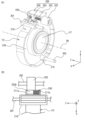
- FIG. 1A and 1B are cross-sectional views showing the configuration of a camera provided with a lens barrel according to the first embodiment.
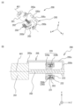
- FIG. 2(A) is a perspective view of the lens holding frame and drive source unit viewed from the object side ( ⁇ Z direction), and FIG. 2(B) is an enlarged view of the vicinity of the first guide portion viewed from the +Y direction. It is a diagram.
- FIG. 3A is a perspective view for explaining the configuration of the drive source unit, and FIG. 3B is a cross-sectional view of the drive source unit.
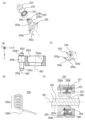
- 4A is an exploded perspective view of the moving part
- FIG. 4B is a partial sectional view of the moving part
- FIG. 4C is a perspective view of the moving part
- FIG. D) is a perspective view of a spring
- FIG. 4E is a cross-sectional view of a moving part
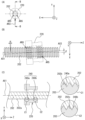
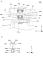
- 5A is a plan view of the lead screw and the annular member as seen from the -Z direction
- FIG. 5B is a view of the lead screw and the annular member as seen from the biasing direction
- 5(C) is a cross-sectional view taken along line BB of FIG. 5(A).
- FIG. 6A is a perspective view showing the drive source unit according to the second embodiment
- FIG. 6B is a view of the drive source unit and the lens holding frame according to the second embodiment as seen from the object side. It is a top view.
- FIG. 7A is a view of part of the drive source unit viewed from the object side
- FIG. 7B is a cross-sectional view taken along line EE of FIG. 6B.
- FIG. 8 is a cross-sectional view taken along line FF of FIG. 6(B).
- FIG. 9A is a perspective view of the drive source unit according to the third embodiment, and FIG. 9B is a view of the drive source unit and the lens holding frame according to the third embodiment viewed from the object side. It is a top view.
- FIG. 10A is a cross-sectional view of a drive source unit according to the third embodiment, and FIG. 10B is a cross-sectional view of a moving portion according to the third embodiment.
- FIG. 11(A) is a plan view of the moving unit according to the third embodiment as seen from the object side ( ⁇ Z direction), and FIG.
- FIG. 12(A) is a perspective view of a drive source unit according to a fourth embodiment
- FIG. 12(B) is a perspective view showing a state in which a moving part is fixed to a lens holding frame
- FIG. C) is a diagram of the moving part and the lead screw viewed from the +Z direction.
- the lens barrel according to the embodiment will be described in detail with reference to the drawings.
- the +Z direction is the direction from the object toward the camera body 3 at the camera position (hereinafter referred to as normal position) when the photographer takes a landscape image with the optical axis OA horizontal.
- the direction toward the right side when viewed from the camera body 3 side at the normal position is defined as the +X direction.
- the upward direction in the normal position is the +Y direction.
- 1A and 1B are cross-sectional views showing the configuration of a camera 1 having a lens barrel 2 according to the first embodiment. 1(A) and 1(B) are different in cutting position.
- the camera 1 includes a camera body 3 and a lens barrel 2.
- the lens barrel 2 is detachably attached to the camera body 3 by engaging with a body mount (not shown) of the camera body 3, which is provided with a lens mount LM at the rear (base end).
- the lens barrel 2 is detachable from the camera body 3, but it is not limited to this, and the lens barrel 2 and the camera body 3 may be integrated.
- the camera body 3 includes an image sensor IS and a control unit (not shown) inside.
- the imaging element IS is composed of a photoelectric conversion element such as a CCD (Charge Coupled Device), for example, and converts the subject image formed by the imaging optical system (the lens barrel 2 attached to the camera body 3) into an electrical signal. do.
- CCD Charge Coupled Device
- the control unit includes a CPU (Central Processing Unit) and the like, and controls the overall operation of the camera 1 related to shooting, including focusing driving in the camera body 3 and the attached lens barrel 2.
- CPU Central Processing Unit
- the lens barrel 2 has lens groups L1 and L2 sequentially arranged along a common optical axis OA.
- the lens group L1 is held by a fixed barrel 10 provided in the lens barrel 2, and the lens group L2 is held by a lens holding frame F2.
- the lens group L2 is a focus lens group that moves in the optical axis OA direction during focusing.
- the lens barrel 2 is not limited to a single-focus lens, and may be a so-called zoom lens whose focal length can be changed.
- each of the lens groups L1 and L2 may be composed of one lens, or may be composed of a plurality of lenses. Also, although a lens barrel composed of two lens groups will be described as an example, there may be three or more lens groups.
- the lens holding frame F2 is driven by the drive source unit 200.
- the lens holding frame F2 and the drive source unit 200 will be described in detail below.
- FIG. 2A is a perspective view of the lens holding frame F2 and the drive source unit 200 as viewed from the subject side (-Z direction), and FIG. It is the enlarged view seen from the direction.
- the lens holding frame F2 has a cylindrical portion 230 that holds the lens group L2. and is provided.
- the first guide portion 210 is fixed to the fixed barrel 10, extends in the optical axis OA direction, and extends the lens holding frame F2 in the optical axis OA direction.
- a guiding guide bar 301 is inserted.
- a rotation restricting bar 302 that is fixed to the fixed barrel 10, extends in the optical axis OA direction, and restricts movement of the lens holding frame F2 in the rotating direction is inserted through the second guide portion 215.
- a first support portion 211a and a second support portion 211b extend from the first guide portion 210 in the -X direction.
- the first support portion 211a and the second support portion 211b support the moving portion 203 (details of which will be described later) of the drive source unit 200 .
- the drive source unit 200 includes a stepping motor 201, a lead screw 202, a moving part 203 that moves along the axis of the lead screw 202 as the lead screw 202 rotates, a member 205;
- FIG. 3(A) is a perspective view for explaining the configuration of the drive source unit 200
- FIG. 3(B) is a cross-sectional view of the drive source unit 200.
- the mounting member 205 includes a first portion 205a fixed to the stepping motor 201, a second portion 205b facing the first portion 205a, and a first portion 205a. and a third portion 205c extending parallel to the lead screw 202 between 205a and the second portion 205b.
- a plurality of holes 205d are formed in the third portion 205c, and the drive source unit 200 is fixed to the fixed barrel 10 by attaching the mounting member 205 to the fixed barrel 10 with screws or the like through the holes 205d. .
- One end of the lead screw 202 is directly connected to the output shaft of the stepping motor 201, and the other end of the lead screw 202 is rotatably supported by the second portion 205b of the mounting member 205.
- the mounting member 205 is mounted on the fixed barrel 10 so that the direction of the axis AX1 of the lead screw 202 is parallel to the direction of the optical axis OA.
- the moving part 203 moves in the direction of the axis AX1 of the lead screw 202 as the lead screw 202 rotates.
- 4A is an exploded perspective view of the moving part 203
- FIG. 4B is a partial cross-sectional view of the moving part 203
- FIG. 4C is a perspective view of the moving part 203
- 4D is a perspective view of the spring 250
- FIG. 4E is a cross-sectional view of the moving portion 203.
- FIG. 4A is an exploded perspective view of the moving part 203
- FIG. 4B is a partial cross-sectional view of the moving part 203
- FIG. 4C is a perspective view of the moving part 203
- 4D is a perspective view of the spring 250
- FIG. 4E is a cross-sectional view of the moving portion 203.
- the moving portion 203 includes a housing portion 203a, a connecting portion 203b, and a spring support portion 203c.
- an annular member 220, a bearing 221, a spacer 222, and a magnet 223 are housed in the housing portion 203a.
- the bearing 221 is not limited to a bearing as long as it is a rotating rolling element that can rotate like a bearing.
- the annular member 220 has a groove 240 on its inner peripheral surface that contacts the thread groove 202 a of the lead screw 202 .
- Groove 240 is a circumferential groove formed over the entire inner circumference of annular member 220 .
- the annular member 220 has a base portion 220a and a fitting portion 220b, and the fitting portion 220b is fitted to the inner ring of the bearing 221 as shown in FIG. Note that the bearing 221 and the annular member 220 may be integrated.
- the outer ring of the bearing 221 is fitted with the inner wall of the housing portion 203a.
- the annular member 220 is rotatably held by the moving portion 203 . That is, the moving part 203 rotatably holds the annular member 220 .
- the spacer 222 is provided so as to cover the outer ring of the bearing 221.
- the magnet 223 is provided so as to face the bearing 221 via the spacer 222 . Since the outer ring of the bearing 221 is covered with the spacer 222, the magnet 223 urges the inner ring of the bearing 221 in the axial direction (optical axis OA direction). As a result, play in the axial direction due to the axial internal clearance of the bearing 221 can be suppressed.
- the spacer 222 may be provided so as to cover the inner ring of the bearing 221 so that the outer ring of the bearing 221 is urged in the axial direction by the magnet. Also, if the play in the axial direction of the bearing 221 is within the required accuracy, the magnet 223 may be omitted. Also, instead of the magnet 223, an urging member such as a spring may be used to suppress play in the axial direction.
- the moving portion 203 has supported portions 203f and 203g that are respectively supported by the first supporting portion 211a and the second supporting portion 211b of the lens holding frame F2.
- the supported portions 203f and 203g of the moving portion 203 are respectively supported by the first supporting portion 211a and the second supporting portion 211b so that the axis AX2 of the spring supporting portion 203c is parallel to the optical axis OA.
- the spring support portion 203c supports the spring 250 by inserting the spring 250 therethrough. Thereby, the spring 250 is positioned between the connecting portion 203b of the moving portion 203 and the second support portion 211b of the lens holding frame F2 (see FIG. 2B).
- the spring 250 has a coil spring portion 250a and a torsion spring portion 250b. As shown in FIG. 2B, one end of the coil spring portion 250a contacts the connecting portion 203b of the moving portion 203, and the other end contacts the second support portion 211b of the lens holding frame F2. As a result, the coil spring portion 250a urges the connection portion 203b of the moving portion 203 and the second support portion 211b of the lens holding frame F2 in a direction away from each other.
- the lens holding frame F2 Since the connecting portion 203b of the moving portion 203 is pressed against the first support portion 211a of the lens holding frame F2 by the coil spring portion 250a, when the moving portion 203 moves in the direction of the optical axis OA, the lens holding frame F2 also moves in the direction of the optical axis OA. Moving.
- the torsion spring portion 250b is locked to a locking portion 203d (see FIG. 4(C)) formed on the outer circumference of the moving portion 203.
- the annular member 220 is biased toward the lead screw 202 in a direction perpendicular to the axis AX1 of the lead screw 202, as indicated by an arrow AR3 in FIG. 4(E). Since the groove 240 of the annular member 220 is pressed against the thread groove 202a of the lead screw 202, looseness between the annular member 220 and the lead screw 202 is suppressed.
- the bottom portion 203e of the housing portion 203a of the moving portion 203 is inclined with respect to the plane perpendicular to the axis AX2 of the spring support portion 203c. Accordingly, the axis AX3 direction of the annular member 220, the bearing 221, the spacer 222, and the magnet 223 is not parallel to the axis AX2 direction of the spring support portion 203c (the axis AX1 direction of the lead screw 202). This point will be described in more detail.
- FIG. 5A is a view of the lead screw 202 and the annular member 220 viewed from the -Z direction
- FIG. FIG. 5C is a cross-sectional view taken along the line BB of FIG. 5A.
- the annular member 220 is inclined according to the lead angle ⁇ of the lead screw 202 . That is, the angle ⁇ formed by the axis AX1 of the lead screw 202 and the axis AX3 of the annular member 220 is substantially equal to the lead angle ⁇ .
- the annular member 220 and the lead screw 202 are in contact with each other on one side of the lead screw 202 in the biasing direction of the spring 250 and separated from each other on the other side.
- the lead screw 202 has a first flank surface 202b and a second flank surface 202c facing each other in the direction of the axis AX1.
- the groove 240 formed on the inner circumference of the annular member 220 includes a first groove 240a and a second groove 240b.
- the first groove 240 a and the second groove 240 b are circumferential grooves formed over the entire inner circumference of the annular member 220 .
- the first groove 240a contacts the first flank surface 202b at a contact point indicated by an arrow AR6 in FIGS. 5A and 5B.
- the second groove 240b contacts the second flank surface 202c at a contact point indicated by an arrow AR5 in FIGS. 5(A) and 5(B). That is, the groove 240 includes a first groove 240a and a second groove 240b that are out of phase with each other.
- Enlarged views indicated by reference numerals C1 and C2 in FIG. 5(C) are cross-sectional views at contact points indicated by arrows AR6 and AR5 in FIGS. 5(A) and 5(B), respectively.
- annular member 220 is inclined in accordance with the lead angle ⁇ of the lead screw 202 and the structure of the first groove 240a and the structure of the second groove 240b.
- Annular member 220 and lead screw 202 abut at at least two points indicated by arrows AR5 and AR6 in (B).
- the two points of contact between the annular member 220 and the lead screw 202 are perpendicular to the direction of the axis AX1 of the lead screw 202 and the direction of the axis AX1 when viewed from the biasing direction in which the spring 250 biases the annular member 220. different in direction. Thereby, the posture of the annular member 220 with respect to the lead screw 202 is stably maintained.
- the contact point indicated by arrow AR5 and the contact point indicated by arrow AR6 are not actually on the same plane, but are shown on the same plane for easy understanding. ing.
- the groove 240 of the annular member 220 includes the first groove 240a and the second groove 240b that are out of phase with each other.
- first groove 240a or the second groove 240b is aligned with the thread groove of the lead screw 202 regardless of whether the annular member 220 moves in the direction of the optical axis OA, toward the object side or toward the camera body 3 side.
- 202 a because there is no gap with the thread groove 202 a of the lead screw 202 ), there is no delay until the annular member 220 follows the lead screw 202 .
- the movement accuracy of the lens holding frame F2 in the optical axis OA direction can be improved, and the position control accuracy of the lens group L2 is improved.
- the annular member 220 Since the annular member 220 is rotatably supported via the bearings 221, when the lead screw 202 rotates, the annular member 220 contacts the first flank surface 202b or the second flank surface 202c of the thread groove 202a of the lead screw 202. It moves in the direction of the axis AX1 of the lead screw 202 while being pushed and rotated. As a result, the moving portion 203 that holds the annular member 220 also moves in the direction of the lead screw axis AX1, so that the lens holding frame F2 connected to the moving portion 203 can be moved in the direction of the optical axis OA.
- the annular member 220 If the annular member 220 is supported so as not to rotate, when the lead screw 202 rotates, the annular member 220 will not rotate, but will contact the first flank surface 202b or the second flank surface 202c of the thread groove 202a of the lead screw 202. It is pushed and moves in the direction of the lead screw axis AX1. At this time, since sliding friction occurs between the annular member 220 and the lead screw 202 , a load due to the sliding friction is applied to the stepping motor 201 .
- the annular member 220 when the annular member 220 is rotatably supported as shown in the first embodiment, the annular member 220 rotates around the axis AX1 of the lead screw 202 when the lead screw 202 rotates. and the lead screw 202 is rolling friction. Since the rolling friction is much smaller than the sliding friction, the load applied to the stepping motor 201 can be reduced when moving the moving part 203 in the direction of the axis AX1. As a result, for example, when the stepping motor 201 of the same output is used to move the lens holding frame F2 of the same weight, the speed is higher than when the annular member 220 is supported so as not to rotate (when sliding friction occurs). The lens holding frame F2 can be moved.
- the lens holding frame F2 when using the stepping motor 201 with the same output, the lens holding frame F2 can be moved, which is heavier than when the annular member 220 is supported so as not to rotate (when sliding friction occurs). Further, when moving the lens holding frame F2 of the same weight, the stepping motor 201 with a smaller output than when the annular member 220 is supported so as not to rotate (when sliding friction occurs) can be used.
- the drive source unit 200 can be miniaturized. Thus, the performance of the drive source unit 200 can be improved.
- the annular member 220 rotates and moves in the direction of the axis AX1 of the lead screw 202. be able to.
- the lens barrel 2 includes the lens holding frame F2 that holds the lens group L2, the stepping motor 201, the annular member 220, and the moving portion 203. , and a spring 250 .
- the lead screw 202 has a thread groove 202 a formed on its outer periphery and is rotationally driven by the stepping motor 201 .
- the annular member 220 has a groove 240 on its inner periphery that contacts the thread groove 202a.
- the moving part 203 is connected to the lens holding frame F2, rotatably holds the annular member 220, and moves along the axis AX1 of the lead screw 202 as the lead screw 202 rotates.
- the spring 250 biases the annular member 220 toward the lead screw in a direction perpendicular to the direction of the axis AX1 of the lead screw 202 .
- the annular member 220 is rotatable around the axis AX1 of the lead screw 202 and rotates as the lead screw 202 rotates.
- rolling friction is generated between the annular member 220 and the lead screw 202 when the annular member 220 moves in the direction of the axis AX1 as the lead screw 202 rotates. Therefore, the weight of the lens holding frame F2 can be increased, the drive source unit 200 can be made smaller, and the lens holding frame F2 can be made smaller than when the annular member 220 is supported so as not to rotate (when sliding friction occurs). You can speed up your movement. Thus, the performance of the drive source unit 200 can be improved.
- the groove 240 of the annular member 220 is a circumferential groove formed over the entire inner circumference. Therefore, when the lead screw 202 rotates, the annular member 220 can be moved in the direction of the axis AX1 of the lead screw 202 .
- the lead screw 202 has a first flank surface 202b and a second flank surface 202c that face each other in the direction of the axis AX1, and the groove 240 of the annular member 220 contacts the first flank surface 202b. It has a first groove 240a in contact and a second groove 240b in contact with the second flank surface 202c.
- first groove 240a or the second groove 240b is aligned with the thread groove of the lead screw 202 regardless of whether the annular member 220 moves in the direction of the optical axis OA, toward the object side or toward the camera body 3 side.
- the movement accuracy of the lens holding frame F2 in the optical axis OA direction can be improved, and the position control accuracy of the lens group L2 is improved.
- the performance of the drive source unit 200 can be improved.
- the annular member 220 is tilted according to the lead angle ⁇ of the lead screw 202 .
- the annular member 220 is inclined in accordance with the lead angle ⁇ of the lead screw 202, and the structure of the first groove 240a and the structure of the second groove 240b allow the thread groove 202a of the lead screw 202 and the annular member
- the groove 240 of 220 contacts at least two points.
- the positions of at least two points where the thread groove 202a of the lead screw 202 and the groove 240 of the annular member 220 abut are in the direction of the axis AX1 of the lead screw 202. , and in a direction orthogonal to the axis AX1 direction.
- the posture of the annular member 220 with respect to the lead screw 202 is stably maintained, so that the annular member 220 can be stably moved.
- a magnet 223 is provided to bias the inner ring of the bearing 221 in the direction of the optical axis OA. As a result, play in the axial direction of the bearing 221 can be reduced.
- the first groove 240a included in the groove 240 of the annular member 220 contacts the first flank surface 202b of the thread groove 202a of the lead screw 202, and the second groove 240b contacts the second flank surface 202b of the thread groove 202a. Although it is in contact with the flank surface 202c, the first groove 240a may be in contact with the second flank surface 202c and the second groove 240b may be in contact with the first flank surface 202b.
- a screw groove may be formed.
- the annular member 220 rotates along with the rotation of the lead screw 202 . Since it can move in the AX1 direction, it is possible to achieve the same effect as in the first embodiment.
- FIG. 6A is a perspective view showing the drive source unit 200A according to the second embodiment
- FIG. 6B shows the drive source unit 200A and the lens holding frame F2A according to the second embodiment on the subject side.
- 1 is a plan view seen from .
- FIG. 7(A) is a view of part of the drive source unit 200A viewed from the object side (-Z direction)
- FIG. 7(B) is a cross-sectional view taken along line EE of FIG. 6(B).
- FIG. 8 is a cross-sectional view taken along line FF of FIG. 6(B).
- symbol is attached
- the lens holding frame F2A according to the second embodiment does not have the first support portion 211a and the second support portion 211b extending in the -X direction from the first guide portion 210. It is different from the lens holding frame F2 according to the first embodiment in that respect.
- illustration of the stepping motor 201 and the mounting member 205 of the drive source unit 200A is omitted.
- the drive source unit 200A includes a stepping motor 201, a lead screw 202, a pair of moving parts 203A, a mounting member 205, and a tension spring 250A.
- a pair of moving parts 203A face each other with the lead screw 202 interposed therebetween.
- Each of the pair of moving parts 203A has a connection part 203i connected to the lens holding frame F2A and a holding part 203h that rotatably holds the annular member 220A.
- the connecting portion 203i has a through hole 203k that penetrates the connecting portion 203i in the optical axis OA direction (Z-axis direction).
- the connection shaft 216c of the lens holding frame F2A is inserted through the through hole 203k, and the cap portion 216b is fixed to the end of the connection shaft 216c. Thereby, the lens holding frame F2A and the moving portion 203A are connected.
- the holding portion 203h holds the bearing 221 by fitting with the inner ring of the bearing 221, and the outer ring of the bearing 221 fits with the inner circumference of the annular member 220A.
- the moving part 203A rotatably holds the annular member 220A. Since the pair of moving parts 203A face each other with the lead screw 202 interposed therebetween, the pair of annular members 220A sandwich the lead screw 202 therebetween.
- a groove 241 that contacts the thread groove 202a of the lead screw 202 is formed on the outer circumference of the annular member 220A.
- the groove 241 includes a first groove 241a that contacts the first flank surface 202b of the thread groove 202a, and a second groove 241b that contacts the second flank surface 202c. That is, the groove 241 includes a first groove 241a and a second groove 241b that are out of phase with each other.
- a locking portion 203j for locking the tension spring 250A is formed at one end (+Y side end) of each of the pair of moving portions 203A. Since the lead screw 202 is sandwiched between the pair of annular members 220A, when the pair of connecting portions 203i is connected to the lens holding frame F2A and the tension spring 250A is locked to the pair of locking portions 203j, as shown in FIG. As indicated by arrows AR11 and AR12 in (A), the pair of annular members 220A are biased toward the lead screw 202, respectively. As a result, play between the annular member 220A and the lead screw 202 is suppressed.
- the two annular members 220A are pushed by the first flank surface 202b or the second flank surface 202c of the thread groove 202a of the lead screw while rotating, and move in the direction of the axis AX1 of the lead screw 202 (that is, , optical axis OA direction). Also in the second embodiment, since the friction generated between the lead screw 202 and the annular member 220A is rolling friction, the load applied to the stepping motor 201 can be reduced compared to when the annular member 220A does not rotate. can.
- FIG. 9A is a perspective view of the drive source unit 200C according to the third embodiment
- FIG. 9B shows the drive source unit 200C and the lens holding frame F2C according to the third embodiment on the subject side.
- 1 is a plan view seen from .
- FIG. 10A is a cross-sectional view of the drive source unit 200C
- FIG. 10B is a cross-sectional view of the moving parts 203C and 203D.
- FIG. 11A is a plan view of moving parts 203C and 203D according to the third embodiment as seen from the -Z direction
- FIG. It is a diagram. Note that the illustration of the stepping motor 201 and the mounting member 205 is omitted in FIG. 9(A).
- a drive source unit 200C includes a stepping motor 201, a lead screw 202, annular members 220C and 220D, moving parts 203C and 203D. and torsion springs 250C and 250D.
- the moving section 203C includes a housing section 213a that houses the annular member 220C and the bearing 221, and a connecting section 213b that connects with the lens holding frame F2C.
- the outer ring of the bearing 221 is fitted with the inner wall of the accommodating portion 213a, and the outer circumference of the annular member 220C is fitted with the inner ring of the bearing 221.
- the annular member 220C is rotatably held by the moving portion 203C.
- a groove 240C that contacts the thread groove 202a of the lead screw 202 is formed on the inner circumference of the annular member 220C.
- the groove 240C contacts the first flank surface 202b of the thread groove 202a of the lead screw 202, for example.
- a bottom portion 213 d of the housing portion 213 a is inclined to match the lead angle of the lead screw 202 .
- the annular member 220C is tilted according to the lead angle. Therefore, as described in the first embodiment, the lead screw 202 and the annular member 220C are separated by at least two angles due to the fact that the annular member 220C is inclined in accordance with the lead angle and the structure of the groove 240C of the annular member 220C.
- the annular member 220C can stably maintain the posture of the annular member 220C with respect to the lead screw 202.
- connection portion 213b is provided with a through hole 213c through which the connection shaft 212a of the lens holding frame F2C is inserted.
- a locking portion 213e for locking one end of the torsion spring 250C is formed on the side surface of the moving portion 203C.
- the torsion spring 250C is supported by the spring support shaft 212c of the lens holding frame F2C, one end is locked by the locking part 213e of the moving part 203C, and the other end is locked to the lens holding frame F2C. is in contact with the first restricting portion 214a.
- the torsion spring 250C biases the annular member 220C toward the lead screw 202 in a direction orthogonal to the direction of the axis AX1 of the lead screw 202, as indicated by an arrow AR21 in FIG.
- the annular member 220C is pressed against the lead screw 202 as indicated by an arrow AR21 in FIG. 11B, and the backlash between the lead screw 202 and the annular member 220C is reduced.
- the moving section 203D includes a housing section 206a that houses the annular member 220D and the bearing 221, and a connecting section 206b that connects with the lens holding frame F2C.
- the outer ring of the bearing 221 is fitted with the inner wall of the housing portion 206a, and the outer circumference of the annular member 220D is fitted with the inner ring of the bearing 221.
- the annular member 220D is rotatably held by the moving portion 203D.
- a groove 240D that contacts the thread groove 202a of the lead screw 202 is formed on the inner circumference of the annular member 220D.
- the groove 240D contacts the second flank surface 202c of the thread groove 202a of the lead screw 202, for example.
- the groove 240C of the annular member 220C or the groove 240D of the annular member 220D is in contact with the thread groove 202a of the lead screw 202. Effects similar to those of the first groove 240a and the second groove 240b formed on the inner circumference of the annular member 220 can be obtained.
- a bottom portion 206 d of the housing portion 206 a is inclined to match the lead angle of the lead screw 202 .
- the annular member 220D is tilted according to the lead angle.
- the lead screw 202 and the annular member 220D are separated by the fact that the annular member 220D is inclined to match the lead angle and the structure of the groove 240D of the annular member 220.
- the annular member 220 ⁇ /b>D abuts at at least two points, and the posture of the annular member 220 ⁇ /b>D with respect to the lead screw 202 can be stably maintained.
- the contact point with the lead screw 202 is Four points are located at different positions in the direction of the axis AX1 and in the direction orthogonal to the direction of the axis AX1. Since this determines the attitude of the lens holding frame F2C, the guide bar 301 may be omitted in the third embodiment. Further, by arranging the annular member 220C and the annular member 220D out of phase with each other in the axial direction, it is possible to suppress the play of the bearing 221 in the axial direction. A member can be omitted.
- connection portion 206b is provided with a through hole 206c through which the connection shaft 212a of the lens holding frame F2C is inserted.
- a locking portion 206e for locking the torsion spring 250D is formed on the side surface of the moving portion 203D.
- the torsion spring 250D is supported by the spring support shaft 212d of the lens holding frame F2C, has one end locked to the locking portion 206e of the moving portion 203C, and has the other end locked to the lens holding frame F2C. is in contact with the second restricting portion 214b.
- the torsion spring 250D urges the annular member 220D toward the lead screw 202 in a direction orthogonal to the direction of the axis AX1 of the lead screw 202, as indicated by an arrow AR22 in FIG. 11(A).
- the annular member 220D is pressed against the lead screw 202 as indicated by an arrow AR22 in FIG. 11B, and the backlash between the lead screw 202 and the annular member 220D is reduced.
- a cap portion 212b is fixed to the end portion of the connection shaft 212a of the lens holding frame F2C that passes through the through hole 213c of the moving portion 203C and the through hole 206c of the moving portion 203D.
- a compression coil spring 260 is provided between the moving portion 203C and the cap portion 212b, and urges the moving portion 203C and the cap portion 212b in a direction away from each other. Accordingly, when the moving parts 203C and 203D move in the optical axis OA direction, the lens holding frame F2C can also move in the optical axis OA direction.
- the stepping motor 201 has less friction than when the annular members 220C and 220D do not rotate. load can be reduced.
- the groove 240C of the annular member 220C contacts the first flank surface 202b of the thread groove 202a of the lead screw 202, and the groove 240D of the annular member 220D contacts the second flank surface 202c of the thread groove 202a.
- the groove 240C may be in contact with the second flank 202c and the groove 240D may be in contact with the first flank 202b.
- FIG. 12(A) is a perspective view of a drive source unit 200D according to the fourth embodiment
- FIG. 12(B) is a perspective view showing a state in which the moving part 203E is fixed to the lens holding frame F2D
- FIG. 12C is a diagram showing the moving part 203E and the lead screw 202 viewed from the +Z direction.
- the shape of the moving part 203E is different from that of the moving part 203 according to the first embodiment.
- the moving part 203E is connected to the lens holding frame F2D by screws or the like.
- the annular member 220 is biased toward the lead screw 202 in a direction perpendicular to the axis AX1 of the lead screw 202 by two torsion springs 250E. Since other configurations are the same as those of the first embodiment, detailed description thereof will be omitted. Also in the configuration according to the fourth embodiment, since the annular member 220 rotates and moves in the optical axis OA direction as the lead screw 202 rotates, the load applied to the stepping motor 201 can be reduced.
Abstract
This lens barrel comprises: a lens retaining frame for retaining a lens; a drive source; a lead screw in which a first threaded groove is formed and which is rotationally driven by the drive source; an annular member having in the inner circumference thereof a groove that comes in contact with the first threaded groove; a movement member which is connected to the lens retaining frame, rotatably retains the annular member, and moves in the axial direction of the lead screw in accordance with rotation of the lead screw; and a biasing part for biasing the annular member toward the lead screw in the direction orthogonal to the axial direction of the lead screw.
Description
レンズ鏡筒、撮像装置、及び駆動装置に関する。
Regarding the lens barrel, imaging device, and driving device.
リードスクリューと、リードスクリューに係合するナットと、を利用して、フォーカスレンズを駆動する機構が提案されている(例えば、特許文献1)。フォーカスレンズを駆動する駆動機構の高性能化が求められている。
A mechanism for driving a focus lens using a lead screw and a nut engaged with the lead screw has been proposed (for example, Patent Document 1). There is a demand for higher performance of a drive mechanism that drives a focus lens.
第1の態様によれば、レンズ鏡筒は、レンズを保持するレンズ保持枠と、駆動源と、第1のねじ溝が形成され、前記駆動源によって回転駆動されるリードスクリューと、前記第1のねじ溝と当接する溝を内周に有する環状部材と、前記レンズ保持枠に接続され、前記環状部材を回転可能に保持し、前記リードスクリューの回転に伴って前記リードスクリューの軸方向に移動する移動部材と、前記リードスクリューの前記軸方向と直交する方向において、前記環状部材を前記リードスクリューに向けて付勢する付勢部と、を備える。
According to the first aspect, the lens barrel includes a lens holding frame that holds a lens, a drive source, a lead screw formed with a first thread groove and rotationally driven by the drive source, the first an annular member having a groove on its inner circumference that abuts on the thread groove of the lens holding frame, is connected to the lens holding frame, rotatably holds the annular member, and moves in the axial direction of the lead screw as the lead screw rotates. and a biasing portion that biases the annular member toward the lead screw in a direction orthogonal to the axial direction of the lead screw.
第2の態様によれば、レンズ鏡筒は、レンズを保持するレンズ保持枠と、駆動源と、ねじ溝が形成され、前記駆動源によって回転駆動されるリードスクリューと、前記ねじ溝と当接する溝を有する回転部材と、前記レンズ保持枠と接続され、前記回転部材を回転可能に保持し、前記リードスクリューの回転に伴って前記リードスクリューの軸方向に移動する移動部と、前記リードスクリューの前記軸と直交する方向において、前記回転部材を前記リードスクリューに向けて付勢する付勢部と、を備える。
According to the second aspect, the lens barrel includes a lens holding frame that holds a lens, a drive source, a lead screw formed with a thread groove and rotationally driven by the drive source, and a contact with the thread groove. a rotating member having a groove; a moving portion connected to the lens holding frame, rotatably holding the rotating member, and moving in the axial direction of the lead screw as the lead screw rotates; an urging portion that urges the rotating member toward the lead screw in a direction orthogonal to the axis.
第3の態様によれば、撮像装置は、上記レンズ鏡筒を備える。
According to the third aspect, an imaging device includes the lens barrel.
第4の態様によれば、駆動装置は、駆動源と、ねじ溝が形成され、前記駆動源によって回転駆動されるリードスクリューと、前記ねじ溝と当接する溝を内周に有する環状部材と、前記環状部材を回転可能に保持する保持部材と、前記リードスクリューの軸と直交する方向において、前記環状部材を前記リードスクリューに向けて付勢する付勢部と、を備え、前記リードスクリューの回転に伴って、前記環状部材は回転しながら前記保持部材とともに前記リードスクリューの軸方向に移動する。
According to a fourth aspect, a driving device includes a driving source, a lead screw formed with a thread groove and rotationally driven by the driving source, an annular member having a groove on its inner circumference that abuts on the thread groove, a holding member that rotatably holds the annular member; and a biasing portion that biases the annular member toward the lead screw in a direction perpendicular to the axis of the lead screw, and rotating the lead screw. Accordingly, the annular member rotates and moves in the axial direction of the lead screw together with the holding member.
なお、後述の実施形態の構成を適宜改良しても良く、また、少なくとも一部を他の構成物に代替させても良い。更に、その配置について特に限定のない構成要件は、実施形態で開示した配置に限らず、その機能を達成できる位置に配置することができる。
It should be noted that the configuration of the embodiment described later may be modified as appropriate, and at least a portion thereof may be replaced with other components. Furthermore, constituent elements whose arrangement is not particularly limited are not limited to the arrangement disclosed in the embodiments, and can be arranged at positions where their functions can be achieved.
以下、実施形態に係るレンズ鏡筒について、図面を参照し、詳細に説明する。なお、以下に示す図面には、説明と理解を容易にするために、適宜にXYZの直交座標系を設けた。この座標系では、撮影者が光軸OAを水平として横長の画像を撮影する場合のカメラ位置(以下、正位置という)において被写体からカメラボディ3側に向かう方向を+Z方向とする。また、正位置においてカメラボディ3側から見て右側に向かう方向を+X方向とする。また、正位置において上側に向かう方向を+Y方向とする。なお、実施形態に示す各部の形状や、長さ、厚みなどの縮尺は必ずしも実物と一致するものではなく、また、各図において、理解を容易にするため、一部の要素の図示を省略している場合がある。また、断面図において一部の要素のハッチングを省略している場合がある。
Hereinafter, the lens barrel according to the embodiment will be described in detail with reference to the drawings. In the drawings shown below, an XYZ orthogonal coordinate system is appropriately provided for easy explanation and understanding. In this coordinate system, the +Z direction is the direction from the object toward the camera body 3 at the camera position (hereinafter referred to as normal position) when the photographer takes a landscape image with the optical axis OA horizontal. Also, the direction toward the right side when viewed from the camera body 3 side at the normal position is defined as the +X direction. Also, the upward direction in the normal position is the +Y direction. Note that the shape, length, thickness, and other scales of each part shown in the embodiments do not necessarily match the actual thing, and in each drawing, some elements are omitted in order to facilitate understanding. may be In some cross-sectional views, hatching of some elements is omitted.
《第1実施形態》
図1(A)及び図1(B)は、第1実施形態に係るレンズ鏡筒2を備えるカメラ1の構成を示す断面図である。図1(A)と図1(B)とは、切断位置が異なる。 <<1st Embodiment>>
1A and 1B are cross-sectional views showing the configuration of acamera 1 having a lens barrel 2 according to the first embodiment. 1(A) and 1(B) are different in cutting position.
図1(A)及び図1(B)は、第1実施形態に係るレンズ鏡筒2を備えるカメラ1の構成を示す断面図である。図1(A)と図1(B)とは、切断位置が異なる。 <<1st Embodiment>>
1A and 1B are cross-sectional views showing the configuration of a
図1(A)及び図1(B)に示すように、カメラ1は、カメラボディ3とレンズ鏡筒2とを備える。レンズ鏡筒2は、後部(基端部)にレンズマウントLMが設けられ、カメラボディ3のボディマウント(不図示)と係合することで、カメラボディ3に着脱可能に装着されている。なお、本実施形態において、レンズ鏡筒2は、カメラボディ3に対して着脱可能であるが、これに限定されず、レンズ鏡筒2とカメラボディ3とは一体であってもよい。
As shown in FIGS. 1(A) and 1(B), the camera 1 includes a camera body 3 and a lens barrel 2. The lens barrel 2 is detachably attached to the camera body 3 by engaging with a body mount (not shown) of the camera body 3, which is provided with a lens mount LM at the rear (base end). In addition, in this embodiment, the lens barrel 2 is detachable from the camera body 3, but it is not limited to this, and the lens barrel 2 and the camera body 3 may be integrated.
カメラボディ3は、内部に撮像素子IS及び制御部(不図示)等を備えている。撮像素子ISは、たとえばCCD(Charge Coupled Device)等の光電変換素子によって構成され、結像光学系(カメラボディ3に装着されたレンズ鏡筒2)によって結像された被写体像を電気信号に変換する。
The camera body 3 includes an image sensor IS and a control unit (not shown) inside. The imaging element IS is composed of a photoelectric conversion element such as a CCD (Charge Coupled Device), for example, and converts the subject image formed by the imaging optical system (the lens barrel 2 attached to the camera body 3) into an electrical signal. do.
制御部は、CPU(Central Processing Unit)等を備え、カメラボディ3及び装着されたレンズ鏡筒2における合焦駆動を含む撮影に係る当該カメラ1全体の動作を統括制御する。
The control unit includes a CPU (Central Processing Unit) and the like, and controls the overall operation of the camera 1 related to shooting, including focusing driving in the camera body 3 and the attached lens barrel 2.
図1(A)及び図1(B)に示すように、本実施形態に係るレンズ鏡筒2は、共通の光軸OAに沿って順次配列されたレンズ群L1及びL2を有する。レンズ群L1は、レンズ鏡筒2が備える固定筒10に保持され、レンズ群L2は、レンズ保持枠F2に保持されている。レンズ群L2は、フォーカシング時に光軸OA方向に移動するフォーカスレンズ群である。
As shown in FIGS. 1(A) and 1(B), the lens barrel 2 according to this embodiment has lens groups L1 and L2 sequentially arranged along a common optical axis OA. The lens group L1 is held by a fixed barrel 10 provided in the lens barrel 2, and the lens group L2 is held by a lens holding frame F2. The lens group L2 is a focus lens group that moves in the optical axis OA direction during focusing.
なお、レンズ鏡筒2は、単焦点のレンズに限定されるものではなく、焦点距離が変更可能ないわゆるズームレンズであってもよい。また、レンズ群L1及びL2はそれぞれ、1枚のレンズで構成されていてもよいし、複数のレンズで構成されていてもよい。また、2つのレンズ群で構成されたレンズ鏡筒を例に説明するが、レンズ群は3つ以上あってもよい。
Note that the lens barrel 2 is not limited to a single-focus lens, and may be a so-called zoom lens whose focal length can be changed. Further, each of the lens groups L1 and L2 may be composed of one lens, or may be composed of a plurality of lenses. Also, although a lens barrel composed of two lens groups will be described as an example, there may be three or more lens groups.
レンズ保持枠F2は、駆動源ユニット200によって駆動される。以下、レンズ保持枠F2と、駆動源ユニット200と、について詳細に説明する。
The lens holding frame F2 is driven by the drive source unit 200. The lens holding frame F2 and the drive source unit 200 will be described in detail below.
図2(A)は、レンズ保持枠F2と駆動源ユニット200とを被写体側(-Z方向)から見た斜視図であり、図2(B)は、後述する第1案内部210付近を+Y方向から見た拡大図である。
FIG. 2A is a perspective view of the lens holding frame F2 and the drive source unit 200 as viewed from the subject side (-Z direction), and FIG. It is the enlarged view seen from the direction.
図2(A)に示すように、レンズ保持枠F2は、レンズ群L2を保持する筒部230を有し、筒部230の外周部には、第1案内部210と、第2案内部215と、が設けられている。
As shown in FIG. 2A, the lens holding frame F2 has a cylindrical portion 230 that holds the lens group L2. and is provided.
図1(B)及び図2(A)に示すように、第1案内部210には、固定筒10に固設され、光軸OA方向に延伸し、レンズ保持枠F2を光軸OA方向に案内するガイドバー301が挿通される。一方、第2案内部215には、固定筒10に固設され、光軸OA方向に延伸し、レンズ保持枠F2の回転方向の動きを規制する回転規制バー302が挿通される。
As shown in FIGS. 1B and 2A, the first guide portion 210 is fixed to the fixed barrel 10, extends in the optical axis OA direction, and extends the lens holding frame F2 in the optical axis OA direction. A guiding guide bar 301 is inserted. On the other hand, a rotation restricting bar 302 that is fixed to the fixed barrel 10, extends in the optical axis OA direction, and restricts movement of the lens holding frame F2 in the rotating direction is inserted through the second guide portion 215. FIG.
図2(B)に示すように、第1案内部210からは、-X方向に、第1支持部211a及び第2支持部211bが延伸している。第1支持部211aおよび第2支持部211bは、駆動源ユニット200の移動部203(詳細は後述する)を支持する。
As shown in FIG. 2(B), a first support portion 211a and a second support portion 211b extend from the first guide portion 210 in the -X direction. The first support portion 211a and the second support portion 211b support the moving portion 203 (details of which will be described later) of the drive source unit 200 .
次に、駆動源ユニット200について説明する。図2(A)に示すように、駆動源ユニット200は、ステッピングモータ201と、リードスクリュー202と、リードスクリュー202の回転に伴ってリードスクリュー202の軸に沿って移動する移動部203と、取付部材205と、を備える。
Next, the drive source unit 200 will be explained. As shown in FIG. 2A, the drive source unit 200 includes a stepping motor 201, a lead screw 202, a moving part 203 that moves along the axis of the lead screw 202 as the lead screw 202 rotates, a member 205;
図3(A)は、駆動源ユニット200の構成について説明するための斜視図であり、図3(B)は、駆動源ユニット200の断面図である。
3(A) is a perspective view for explaining the configuration of the drive source unit 200, and FIG. 3(B) is a cross-sectional view of the drive source unit 200. FIG.
図3(A)及び図3(B)に示すように、取付部材205は、ステッピングモータ201に固定される第1部分205aと、第1部分205aと対向する第2部分205bと、第1部分205aと第2部分205bとの間でリードスクリュー202と平行に延在する第3部分205cとを有する。第3部分205cには、複数の穴205dが形成されており、当該穴205dを介して取付部材205をビスなどによって固定筒10に取り付けることによって、駆動源ユニット200が固定筒10に固定される。
As shown in FIGS. 3A and 3B, the mounting member 205 includes a first portion 205a fixed to the stepping motor 201, a second portion 205b facing the first portion 205a, and a first portion 205a. and a third portion 205c extending parallel to the lead screw 202 between 205a and the second portion 205b. A plurality of holes 205d are formed in the third portion 205c, and the drive source unit 200 is fixed to the fixed barrel 10 by attaching the mounting member 205 to the fixed barrel 10 with screws or the like through the holes 205d. .
リードスクリュー202の一端部は、ステッピングモータ201の出力軸に直結され、リードスクリュー202の他端部は取付部材205の第2部分205bによって回転可能に支持されている。なお、取付部材205は、リードスクリュー202の軸AX1方向が光軸OA方向と平行になるように固定筒10に取り付けられる。
One end of the lead screw 202 is directly connected to the output shaft of the stepping motor 201, and the other end of the lead screw 202 is rotatably supported by the second portion 205b of the mounting member 205. The mounting member 205 is mounted on the fixed barrel 10 so that the direction of the axis AX1 of the lead screw 202 is parallel to the direction of the optical axis OA.
移動部203は、リードスクリュー202の回転に伴ってリードスクリュー202の軸AX1方向に移動する。図4(A)は、移動部203の分解斜視図であり、図4(B)は、移動部203の部分断面図であり、図4(C)は、移動部203の斜視図であり、図4(D)は、バネ250の斜視図であり、図4(E)は、移動部203の断面図である。
The moving part 203 moves in the direction of the axis AX1 of the lead screw 202 as the lead screw 202 rotates. 4A is an exploded perspective view of the moving part 203, FIG. 4B is a partial cross-sectional view of the moving part 203, FIG. 4C is a perspective view of the moving part 203, 4D is a perspective view of the spring 250, and FIG. 4E is a cross-sectional view of the moving portion 203. FIG.
図4(A)及び図4(B)に示すように、移動部203は、収容部203aと、接続部203bと、バネ支持部203cと、を備える。
As shown in FIGS. 4A and 4B, the moving portion 203 includes a housing portion 203a, a connecting portion 203b, and a spring support portion 203c.
図4(A)に示すように、収容部203aには、環状部材220と、ベアリング221と、スペーサ222と、磁石223と、が収容されている。なお、ベアリング221は、ベアリングに限定されず、ベアリングのように回転可能な回転転動体であればよい。
As shown in FIG. 4A, an annular member 220, a bearing 221, a spacer 222, and a magnet 223 are housed in the housing portion 203a. Note that the bearing 221 is not limited to a bearing as long as it is a rotating rolling element that can rotate like a bearing.
環状部材220は、内周面に、リードスクリュー202のねじ溝202aと接触する溝240を有する。溝240は、環状部材220の内周の全周にわたって形成される周溝である。また、環状部材220は、ベース部220aと、嵌合部220bと、を有し、図4(E)に示すように、嵌合部220bは、ベアリング221の内輪に嵌合する。なお、ベアリング221と環状部材220とは一体であってもよい。
The annular member 220 has a groove 240 on its inner peripheral surface that contacts the thread groove 202 a of the lead screw 202 . Groove 240 is a circumferential groove formed over the entire inner circumference of annular member 220 . The annular member 220 has a base portion 220a and a fitting portion 220b, and the fitting portion 220b is fitted to the inner ring of the bearing 221 as shown in FIG. Note that the bearing 221 and the annular member 220 may be integrated.
図4(E)に示すように、ベアリング221の外輪は、収容部203aの内壁と嵌合する。これにより、環状部材220は、移動部203に回転可能に保持される。すなわち、移動部203は、環状部材220を回転可能に保持する。
As shown in FIG. 4(E), the outer ring of the bearing 221 is fitted with the inner wall of the housing portion 203a. Thereby, the annular member 220 is rotatably held by the moving portion 203 . That is, the moving part 203 rotatably holds the annular member 220 .
図4(E)に示すように、スペーサ222は、ベアリング221の外輪を覆うように設けられている。磁石223は、スペーサ222を介して、ベアリング221と対向するように設けられている。ベアリング221の外輪がスペーサ222によって覆われているため、磁石223によって、ベアリング221の内輪が軸方向(光軸OA方向)に付勢される。これにより、ベアリング221のアキシアル内部すきまによる軸方向のガタを抑制することができる。なお、スペーサ222をベアリング221の内輪を覆うように設け、磁石によって、ベアリング221の外輪が軸方向に付勢されるようにしてもよい。また、ベアリング221の軸方向のガタが要求精度内であれば磁石223は省略してもよい。また、磁石223の代わりに、バネ等の付勢部材を用いて軸方向のガタを抑制してもよい。
As shown in FIG. 4(E), the spacer 222 is provided so as to cover the outer ring of the bearing 221. The magnet 223 is provided so as to face the bearing 221 via the spacer 222 . Since the outer ring of the bearing 221 is covered with the spacer 222, the magnet 223 urges the inner ring of the bearing 221 in the axial direction (optical axis OA direction). As a result, play in the axial direction due to the axial internal clearance of the bearing 221 can be suppressed. The spacer 222 may be provided so as to cover the inner ring of the bearing 221 so that the outer ring of the bearing 221 is urged in the axial direction by the magnet. Also, if the play in the axial direction of the bearing 221 is within the required accuracy, the magnet 223 may be omitted. Also, instead of the magnet 223, an urging member such as a spring may be used to suppress play in the axial direction.
また、図4(B)に示すように、移動部203は、レンズ保持枠F2の第1支持部211aおよび第2支持部211bにそれぞれ支持される被支持部203f及び203gを有する。なお、移動部203の被支持部203f及び203gは、バネ支持部203cの軸AX2が光軸OAと平行になるよう、第1支持部211aおよび第2支持部211bにそれぞれ支持される。
Further, as shown in FIG. 4B, the moving portion 203 has supported portions 203f and 203g that are respectively supported by the first supporting portion 211a and the second supporting portion 211b of the lens holding frame F2. The supported portions 203f and 203g of the moving portion 203 are respectively supported by the first supporting portion 211a and the second supporting portion 211b so that the axis AX2 of the spring supporting portion 203c is parallel to the optical axis OA.
被支持部203f及び203gが第1支持部211aおよび第2支持部211bにそれぞれ支持された状態において、移動部203の接続部203bの端面203b1は、レンズ保持枠F2の第1支持部211aに当接する(図2(B)参照)。
When the supported portions 203f and 203g are supported by the first support portion 211a and the second support portion 211b, respectively, the end surface 203b1 of the connecting portion 203b of the moving portion 203 contacts the first support portion 211a of the lens holding frame F2. contact (see FIG. 2(B)).
バネ支持部203cは、バネ250を挿通し、バネ250を支持する。これにより、バネ250は、移動部203の接続部203bと、レンズ保持枠F2の第2支持部211bと、の間に位置する(図2(B)参照)。
The spring support portion 203c supports the spring 250 by inserting the spring 250 therethrough. Thereby, the spring 250 is positioned between the connecting portion 203b of the moving portion 203 and the second support portion 211b of the lens holding frame F2 (see FIG. 2B).
図4(D)に示すように、バネ250は、コイルばね部250aと、ねじりバネ部250bと、を有する。図2(B)に示すように、コイルばね部250aの一端は、移動部203の接続部203bと当接し、他端はレンズ保持枠F2の第2支持部211bと当接する。これにより、コイルばね部250aは、移動部203の接続部203bとレンズ保持枠F2の第2支持部211bとを、互いに離間する方向に付勢する。コイルばね部250aによって移動部203の接続部203bがレンズ保持枠F2の第1支持部211aに押し付けられるため、移動部203が光軸OA方向に移動すると、レンズ保持枠F2も光軸OA方向に移動する。
As shown in FIG. 4(D), the spring 250 has a coil spring portion 250a and a torsion spring portion 250b. As shown in FIG. 2B, one end of the coil spring portion 250a contacts the connecting portion 203b of the moving portion 203, and the other end contacts the second support portion 211b of the lens holding frame F2. As a result, the coil spring portion 250a urges the connection portion 203b of the moving portion 203 and the second support portion 211b of the lens holding frame F2 in a direction away from each other. Since the connecting portion 203b of the moving portion 203 is pressed against the first support portion 211a of the lens holding frame F2 by the coil spring portion 250a, when the moving portion 203 moves in the direction of the optical axis OA, the lens holding frame F2 also moves in the direction of the optical axis OA. Moving.
ねじりバネ部250bは、移動部203の外周に形成された係止部203d(図4(C)参照)に係止される。これにより、図4(E)に矢印AR3で示すように、環状部材220がリードスクリュー202の軸AX1と直交する方向においてリードスクリュー202に向かって付勢される。環状部材220の溝240がリードスクリュー202のねじ溝202aに押し付けられるため、環状部材220とリードスクリュー202との間のガタが抑制される。
The torsion spring portion 250b is locked to a locking portion 203d (see FIG. 4(C)) formed on the outer circumference of the moving portion 203. As a result, the annular member 220 is biased toward the lead screw 202 in a direction perpendicular to the axis AX1 of the lead screw 202, as indicated by an arrow AR3 in FIG. 4(E). Since the groove 240 of the annular member 220 is pressed against the thread groove 202a of the lead screw 202, looseness between the annular member 220 and the lead screw 202 is suppressed.
図4(B)に示すように、移動部203の収容部203aの底部203eは、バネ支持部203cの軸AX2に垂直な平面に対して傾斜している。これにより、環状部材220、ベアリング221、スペーサ222、及び磁石223の軸AX3方向は、バネ支持部203cの軸AX2方向(リードスクリュー202の軸AX1方向)とは平行にならない。この点について、より詳細に説明する。
As shown in FIG. 4B, the bottom portion 203e of the housing portion 203a of the moving portion 203 is inclined with respect to the plane perpendicular to the axis AX2 of the spring support portion 203c. Accordingly, the axis AX3 direction of the annular member 220, the bearing 221, the spacer 222, and the magnet 223 is not parallel to the axis AX2 direction of the spring support portion 203c (the axis AX1 direction of the lead screw 202). This point will be described in more detail.
図5(A)は、リードスクリュー202と環状部材220とを-Z方向から見た図であり、図5(B)は、リードスクリュー202と環状部材220とを、環状部材220の付勢方向(図5(A)において矢印AR3で示す方向)から見た図であり、図5(C)は、図5(A)のB-B線断面図である。
5A is a view of the lead screw 202 and the annular member 220 viewed from the -Z direction, and FIG. FIG. 5C is a cross-sectional view taken along the line BB of FIG. 5A.
図5(B)に示すように、本実施形態では、環状部材220を、リードスクリュー202のリード角αに合わせて傾けている。すなわち、リードスクリュー202の軸AX1と、環状部材220の軸AX3とがなす角βは、リード角αと略等しくなっている。
As shown in FIG. 5(B), in this embodiment, the annular member 220 is inclined according to the lead angle α of the lead screw 202 . That is, the angle β formed by the axis AX1 of the lead screw 202 and the axis AX3 of the annular member 220 is substantially equal to the lead angle α.
図5(C)に示すように、環状部材220とリードスクリュー202とは、バネ250の付勢方向において、リードスクリュー202の一方側で当接し、他方側で離間している。リードスクリュー202は軸AX1方向において対向する第1フランク面202bと第2フランク面202cとを有する。環状部材220の内周に形成された溝240は、第1溝240aと、第2溝240bと、を備える。第1溝240aと、第2溝240bと、は、環状部材220の内周の全周にわたって形成される周溝である。第1溝240aは、図5(A)及び図5(B)において矢印AR6で示す当接点において第1フランク面202bと当接する。一方、第2溝240bは、図5(A)及び図5(B)において矢印AR5で示す当接点において、第2フランク面202cと当接する。すなわち、溝240は、互いに位相が異なる第1溝240aと、第2溝240bと、を備える。なお、図5(C)において符号C1及び符号C2で示す拡大図はそれぞれ、図5(A)及び図5(B)において矢印AR6およびAR5で示す当接点における断面図である。
As shown in FIG. 5(C), the annular member 220 and the lead screw 202 are in contact with each other on one side of the lead screw 202 in the biasing direction of the spring 250 and separated from each other on the other side. The lead screw 202 has a first flank surface 202b and a second flank surface 202c facing each other in the direction of the axis AX1. The groove 240 formed on the inner circumference of the annular member 220 includes a first groove 240a and a second groove 240b. The first groove 240 a and the second groove 240 b are circumferential grooves formed over the entire inner circumference of the annular member 220 . The first groove 240a contacts the first flank surface 202b at a contact point indicated by an arrow AR6 in FIGS. 5A and 5B. On the other hand, the second groove 240b contacts the second flank surface 202c at a contact point indicated by an arrow AR5 in FIGS. 5(A) and 5(B). That is, the groove 240 includes a first groove 240a and a second groove 240b that are out of phase with each other. Enlarged views indicated by reference numerals C1 and C2 in FIG. 5(C) are cross-sectional views at contact points indicated by arrows AR6 and AR5 in FIGS. 5(A) and 5(B), respectively.
このように、環状部材220が、リードスクリュー202のリード角αに合わせて傾いていることと、第1溝240aの構造および第2溝240bの構造と、により、図5(A)及び図5(B)において矢印AR5およびAR6で示す少なくとも2点において、環状部材220とリードスクリュー202とが当接する。環状部材220とリードスクリュー202とが当接する2点の位置は、バネ250が環状部材220を付勢する付勢方向から見た場合、リードスクリュー202の軸AX1方向、及び軸AX1方向と直交する方向において異なっている。これにより、リードスクリュー202に対する環状部材220の姿勢が安定的に維持される。なお、図5(A)において、矢印AR5で示す当接点と、矢印AR6で示す当接点とは、実際には同一平面上にあるわけではないが、理解を容易にするため同一平面上に示している。
5A and 5 due to the fact that the annular member 220 is inclined in accordance with the lead angle α of the lead screw 202 and the structure of the first groove 240a and the structure of the second groove 240b. Annular member 220 and lead screw 202 abut at at least two points indicated by arrows AR5 and AR6 in (B). The two points of contact between the annular member 220 and the lead screw 202 are perpendicular to the direction of the axis AX1 of the lead screw 202 and the direction of the axis AX1 when viewed from the biasing direction in which the spring 250 biases the annular member 220. different in direction. Thereby, the posture of the annular member 220 with respect to the lead screw 202 is stably maintained. In FIG. 5A, the contact point indicated by arrow AR5 and the contact point indicated by arrow AR6 are not actually on the same plane, but are shown on the same plane for easy understanding. ing.
また、上述したように、環状部材220の溝240は、互いに位相が異なる第1溝240aと、第2溝240bと、を備える。これにより、環状部材220が光軸OA方向において被写体側及びカメラボディ3側のいずれの方向に移動する場合にも、第1溝240aおよび第2溝240bのいずれかが、リードスクリュー202のねじ溝202aと接触しているため(リードスクリュー202のねじ溝202aとの間に隙間が生じないため)、環状部材220がリードスクリュー202に追従するまでに遅延が生じない。これにより、レンズ保持枠F2の光軸OA方向の移動精度を向上させることができ、レンズ群L2の位置制御精度が向上する。
Also, as described above, the groove 240 of the annular member 220 includes the first groove 240a and the second groove 240b that are out of phase with each other. As a result, either the first groove 240a or the second groove 240b is aligned with the thread groove of the lead screw 202 regardless of whether the annular member 220 moves in the direction of the optical axis OA, toward the object side or toward the camera body 3 side. 202 a (because there is no gap with the thread groove 202 a of the lead screw 202 ), there is no delay until the annular member 220 follows the lead screw 202 . As a result, the movement accuracy of the lens holding frame F2 in the optical axis OA direction can be improved, and the position control accuracy of the lens group L2 is improved.
環状部材220はベアリング221を介して回転可能に支持されているため、リードスクリュー202が回転すると、環状部材220は、リードスクリュー202のねじ溝202aの第1フランク面202b又は第2フランク面202cに押されて回転しながらリードスクリュー202の軸AX1方向に移動する。これにより、環状部材220を保持する移動部203もリードスクリューの軸AX1方向に移動するため、移動部203と接続されたレンズ保持枠F2を光軸OA方向に移動させることができる。
Since the annular member 220 is rotatably supported via the bearings 221, when the lead screw 202 rotates, the annular member 220 contacts the first flank surface 202b or the second flank surface 202c of the thread groove 202a of the lead screw 202. It moves in the direction of the axis AX1 of the lead screw 202 while being pushed and rotated. As a result, the moving portion 203 that holds the annular member 220 also moves in the direction of the lead screw axis AX1, so that the lens holding frame F2 connected to the moving portion 203 can be moved in the direction of the optical axis OA.
環状部材220が回転できないように支持されている場合、リードスクリュー202が回転すると、環状部材220は回転することなく、リードスクリュー202のねじ溝202aの第1フランク面202b又は第2フランク面202cに押されてリードスクリューの軸AX1方向に移動することになる。このとき、環状部材220とリードスクリュー202との間にはすべり摩擦が生じるため、ステッピングモータ201にすべり摩擦による負荷がかかる。
If the annular member 220 is supported so as not to rotate, when the lead screw 202 rotates, the annular member 220 will not rotate, but will contact the first flank surface 202b or the second flank surface 202c of the thread groove 202a of the lead screw 202. It is pushed and moves in the direction of the lead screw axis AX1. At this time, since sliding friction occurs between the annular member 220 and the lead screw 202 , a load due to the sliding friction is applied to the stepping motor 201 .
一方、第1実施形態に示すように環状部材220が回転可能に支持されている場合、リードスクリュー202が回転すると、環状部材220は、リードスクリュー202の軸AX1回りに回転するため、環状部材220とリードスクリュー202との間に生じる摩擦は、転がり摩擦となる。転がり摩擦はすべり摩擦に比べて非常に小さいので、移動部203を軸AX1方向に移動させるときにステッピングモータ201にかかる負荷を低減することができる。これにより、例えば、同じ出力のステッピングモータ201を用いて同重量のレンズ保持枠F2を移動させる場合、環状部材220が回転できないように支持されている場合(すべり摩擦が生じる場合)よりも高速にレンズ保持枠F2を移動させることができる。また、例えば、同じ出力のステッピングモータ201を用いる場合、環状部材220が回転できないように支持されている場合(すべり摩擦が生じる場合)よりも重いレンズ保持枠F2を移動させることができる。また、同重量のレンズ保持枠F2を移動させる場合、環状部材220が回転できないように支持されている場合(すべり摩擦が生じる場合)よりも小さな出力のステッピングモータ201を使用することができるため、駆動源ユニット200を小型化できる。このように駆動源ユニット200を高性能化できる。
また、リードスクリュー202のねじ溝202aの形状と環状部材220の溝240の形状とが異なっているため、リードスクリュー202が回転すると環状部材220は回転しながらリードスクリュー202の軸AX1方向に移動することができる。 On the other hand, when theannular member 220 is rotatably supported as shown in the first embodiment, the annular member 220 rotates around the axis AX1 of the lead screw 202 when the lead screw 202 rotates. and the lead screw 202 is rolling friction. Since the rolling friction is much smaller than the sliding friction, the load applied to the stepping motor 201 can be reduced when moving the moving part 203 in the direction of the axis AX1. As a result, for example, when the stepping motor 201 of the same output is used to move the lens holding frame F2 of the same weight, the speed is higher than when the annular member 220 is supported so as not to rotate (when sliding friction occurs). The lens holding frame F2 can be moved. Further, for example, when using the stepping motor 201 with the same output, the lens holding frame F2 can be moved, which is heavier than when the annular member 220 is supported so as not to rotate (when sliding friction occurs). Further, when moving the lens holding frame F2 of the same weight, the stepping motor 201 with a smaller output than when the annular member 220 is supported so as not to rotate (when sliding friction occurs) can be used. The drive source unit 200 can be miniaturized. Thus, the performance of the drive source unit 200 can be improved.
Further, since the shape of thethread groove 202a of the lead screw 202 and the shape of the groove 240 of the annular member 220 are different, when the lead screw 202 rotates, the annular member 220 rotates and moves in the direction of the axis AX1 of the lead screw 202. be able to.
また、リードスクリュー202のねじ溝202aの形状と環状部材220の溝240の形状とが異なっているため、リードスクリュー202が回転すると環状部材220は回転しながらリードスクリュー202の軸AX1方向に移動することができる。 On the other hand, when the
Further, since the shape of the
以上、詳細に説明したように、本第1実施形態によれば、レンズ鏡筒2は、レンズ群L2を保持するレンズ保持枠F2と、ステッピングモータ201と、環状部材220と、移動部203と、バネ250と、を備える。リードスクリュー202は、外周にねじ溝202aが形成され、ステッピングモータ201によって回転駆動される。環状部材220は、ねじ溝202aと当接する溝240を内周に有する。移動部203は、レンズ保持枠F2に接続され、環状部材220を回転可能に保持し、リードスクリュー202の回転に伴ってリードスクリュー202の軸AX1方向に移動する。バネ250は、リードスクリュー202の軸AX1方向と直交する方向において、環状部材220をリードスクリューに向けて付勢する。環状部材220は、リードスクリュー202の軸AX1回りに回転可能であり、リードスクリュー202の回転に伴って回転する。これにより、上述したように、リードスクリュー202の回転に伴って、環状部材220が軸AX1方向に移動するときに、環状部材220とリードスクリュー202との間に生じるのは転がり摩擦となる。そのため、環状部材220が回転できないように支持されている場合(すべり摩擦が生じる場合)よりも、レンズ保持枠F2の重量を増加させたり、駆動源ユニット200を小型化したり、レンズ保持枠F2の移動を高速化したりすることができる。このように、駆動源ユニット200を高性能化することができる。
As described in detail above, according to the first embodiment, the lens barrel 2 includes the lens holding frame F2 that holds the lens group L2, the stepping motor 201, the annular member 220, and the moving portion 203. , and a spring 250 . The lead screw 202 has a thread groove 202 a formed on its outer periphery and is rotationally driven by the stepping motor 201 . The annular member 220 has a groove 240 on its inner periphery that contacts the thread groove 202a. The moving part 203 is connected to the lens holding frame F2, rotatably holds the annular member 220, and moves along the axis AX1 of the lead screw 202 as the lead screw 202 rotates. The spring 250 biases the annular member 220 toward the lead screw in a direction perpendicular to the direction of the axis AX1 of the lead screw 202 . The annular member 220 is rotatable around the axis AX1 of the lead screw 202 and rotates as the lead screw 202 rotates. As a result, as described above, rolling friction is generated between the annular member 220 and the lead screw 202 when the annular member 220 moves in the direction of the axis AX1 as the lead screw 202 rotates. Therefore, the weight of the lens holding frame F2 can be increased, the drive source unit 200 can be made smaller, and the lens holding frame F2 can be made smaller than when the annular member 220 is supported so as not to rotate (when sliding friction occurs). You can speed up your movement. Thus, the performance of the drive source unit 200 can be improved.
また、本第1実施形態において、環状部材220の溝240は、内周の全周にわたって形成される周溝である。これにより、リードスクリュー202が回転したときに、環状部材220をリードスクリュー202の軸AX1方向に移動させることができる。
Further, in the first embodiment, the groove 240 of the annular member 220 is a circumferential groove formed over the entire inner circumference. Thereby, when the lead screw 202 rotates, the annular member 220 can be moved in the direction of the axis AX1 of the lead screw 202 .
また、本第1実施形態において、リードスクリュー202は軸AX1方向において対向する第1フランク面202bと第2フランク面202cとを有し、環状部材220の溝240は、第1フランク面202bと当接する第1溝240aと、第2フランク面202cと当接する第2溝240bと、を有する。これにより、環状部材220が光軸OA方向において被写体側及びカメラボディ3側のいずれの方向に移動する場合にも、第1溝240aおよび第2溝240bのいずれかが、リードスクリュー202のねじ溝202aと接触しているため(リードスクリュー202のねじ溝202aとの間に隙間が生じないため)、環状部材220がリードスクリュー202に追従するまでに遅延が生じない。したがって、レンズ保持枠F2の光軸OA方向の移動精度を向上させることができ、レンズ群L2の位置制御精度が向上する。このように、駆動源ユニット200を高性能化することができる。
In addition, in the first embodiment, the lead screw 202 has a first flank surface 202b and a second flank surface 202c that face each other in the direction of the axis AX1, and the groove 240 of the annular member 220 contacts the first flank surface 202b. It has a first groove 240a in contact and a second groove 240b in contact with the second flank surface 202c. As a result, either the first groove 240a or the second groove 240b is aligned with the thread groove of the lead screw 202 regardless of whether the annular member 220 moves in the direction of the optical axis OA, toward the object side or toward the camera body 3 side. 202 a (because there is no gap with the thread groove 202 a of the lead screw 202 ), there is no delay until the annular member 220 follows the lead screw 202 . Therefore, the movement accuracy of the lens holding frame F2 in the optical axis OA direction can be improved, and the position control accuracy of the lens group L2 is improved. Thus, the performance of the drive source unit 200 can be improved.
また、本第1実施形態において、環状部材220は、リードスクリュー202のリード角αに合わせて傾けられている。環状部材220が、リードスクリュー202のリード角αに合わせて傾けられていることと、第1溝240aの構造及び第2溝240bの構造と、により、リードスクリュー202のねじ溝202aと、環状部材220の溝240とは、少なくとも2点で当接する。バネ250が環状部材220を付勢する付勢方向から見た場合、リードスクリュー202のねじ溝202aと環状部材220の溝240とが当接する少なくとも2点の位置は、リードスクリュー202の軸AX1方向、及び軸AX1方向と直交する方向において異なっている。これにより、リードスクリュー202に対する環状部材220の姿勢が安定的に維持されるため、環状部材220を安定して移動させることができる。
Also, in the first embodiment, the annular member 220 is tilted according to the lead angle α of the lead screw 202 . The annular member 220 is inclined in accordance with the lead angle α of the lead screw 202, and the structure of the first groove 240a and the structure of the second groove 240b allow the thread groove 202a of the lead screw 202 and the annular member The groove 240 of 220 contacts at least two points. When viewed from the urging direction in which the spring 250 urges the annular member 220, the positions of at least two points where the thread groove 202a of the lead screw 202 and the groove 240 of the annular member 220 abut are in the direction of the axis AX1 of the lead screw 202. , and in a direction orthogonal to the axis AX1 direction. As a result, the posture of the annular member 220 with respect to the lead screw 202 is stably maintained, so that the annular member 220 can be stably moved.
また、本第1実施形態において、ベアリング221の内輪を光軸OA方向に付勢する磁石223が設けられている。これにより、ベアリング221の軸方向のガタを低減することができる。
Also, in the first embodiment, a magnet 223 is provided to bias the inner ring of the bearing 221 in the direction of the optical axis OA. As a result, play in the axial direction of the bearing 221 can be reduced.
なお、上記第1実施形態において、環状部材220の溝240が備える第1溝240aがリードスクリュー202のねじ溝202aの第1フランク面202bに接触し、第2溝240bがねじ溝202aの第2フランク面202cに接触していたが、第1溝240aが第2フランク面202cに接触し、第2溝240bが第1フランク面202bに接触していてもよい。
In the above-described first embodiment, the first groove 240a included in the groove 240 of the annular member 220 contacts the first flank surface 202b of the thread groove 202a of the lead screw 202, and the second groove 240b contacts the second flank surface 202b of the thread groove 202a. Although it is in contact with the flank surface 202c, the first groove 240a may be in contact with the second flank surface 202c and the second groove 240b may be in contact with the first flank surface 202b.
なお、上記第1実施形態において、環状部材220の内周には溝240が形成されていたが、ねじ溝が形成されていてもよい。この場合、リードスクリュー202のねじ溝202aのピッチと、環状部材220のねじ溝のピッチとを異ならせることで、リードスクリュー202の回転に伴って、環状部材220は回転しながらリードスクリュー202の軸AX1方向に移動できるため、上記第1実施形態と同様の効果を達成することができる。
Although the groove 240 is formed in the inner circumference of the annular member 220 in the first embodiment, a screw groove may be formed. In this case, by making the pitch of the thread groove 202 a of the lead screw 202 different from the pitch of the thread groove of the annular member 220 , the annular member 220 rotates along with the rotation of the lead screw 202 . Since it can move in the AX1 direction, it is possible to achieve the same effect as in the first embodiment.
《第2実施形態》
第2実施形態では、環状部材220Aが外周に溝241を有する場合の構成について説明する。 <<Second embodiment>>
In the second embodiment, a configuration in which anannular member 220A has a groove 241 on its outer periphery will be described.
第2実施形態では、環状部材220Aが外周に溝241を有する場合の構成について説明する。 <<Second embodiment>>
In the second embodiment, a configuration in which an
図6(A)は、第2実施形態に係る駆動源ユニット200Aを示す斜視図であり、図6(B)は、駆動源ユニット200Aと第2実施形態に係るレンズ保持枠F2Aとを被写体側から見た平面図である。図7(A)は、駆動源ユニット200Aの一部を被写体側(-Z方向)から見た図であり、図7(B)は、図6(B)のE-E線断面図である。図8は、図6(B)のF-F線断面図である。なお、以後の実施形態において、第1実施形態と同じ構成については、同一の符号を付し、その詳細な説明を省略する。
FIG. 6A is a perspective view showing the drive source unit 200A according to the second embodiment, and FIG. 6B shows the drive source unit 200A and the lens holding frame F2A according to the second embodiment on the subject side. 1 is a plan view seen from . FIG. 7(A) is a view of part of the drive source unit 200A viewed from the object side (-Z direction), and FIG. 7(B) is a cross-sectional view taken along line EE of FIG. 6(B). . FIG. 8 is a cross-sectional view taken along line FF of FIG. 6(B). In addition, in subsequent embodiments, the same code|symbol is attached|subjected about the same structure as 1st Embodiment, and the detailed description is abbreviate|omitted.
図6(B)に示すように、第2実施形態に係るレンズ保持枠F2Aは、第1案内部210から-X方向に延伸する第1支持部211aおよび第2支持部211bを有していない点が、第1実施形態に係るレンズ保持枠F2と異なる。なお、図6(B)において、駆動源ユニット200Aのステッピングモータ201と取付部材205の図示を省略している。
As shown in FIG. 6B, the lens holding frame F2A according to the second embodiment does not have the first support portion 211a and the second support portion 211b extending in the -X direction from the first guide portion 210. It is different from the lens holding frame F2 according to the first embodiment in that respect. In FIG. 6B, illustration of the stepping motor 201 and the mounting member 205 of the drive source unit 200A is omitted.
図6(A)に示すように、駆動源ユニット200Aは、ステッピングモータ201と、リードスクリュー202と、一対の移動部203Aと、取付部材205と、引張バネ250Aと、を備える。
As shown in FIG. 6(A), the drive source unit 200A includes a stepping motor 201, a lead screw 202, a pair of moving parts 203A, a mounting member 205, and a tension spring 250A.
一対の移動部203Aはリードスクリュー202を挟んで対向する。一対の移動部203Aはそれぞれ、レンズ保持枠F2Aに接続される接続部203iと、環状部材220Aを回転可能に保持する保持部203hと、を有する。
A pair of moving parts 203A face each other with the lead screw 202 interposed therebetween. Each of the pair of moving parts 203A has a connection part 203i connected to the lens holding frame F2A and a holding part 203h that rotatably holds the annular member 220A.
図7(A)に示すように、接続部203iは、光軸OA方向(Z軸方向)に接続部203iを貫通する貫通孔203kを有する。図8に示すように、貫通孔203kには、レンズ保持枠F2Aの接続軸216cが挿通され、接続軸216cの端部には、キャップ部216bが固定されている。これにより、レンズ保持枠F2Aと、移動部203Aとが接続される。
As shown in FIG. 7A, the connecting portion 203i has a through hole 203k that penetrates the connecting portion 203i in the optical axis OA direction (Z-axis direction). As shown in FIG. 8, the connection shaft 216c of the lens holding frame F2A is inserted through the through hole 203k, and the cap portion 216b is fixed to the end of the connection shaft 216c. Thereby, the lens holding frame F2A and the moving portion 203A are connected.
図7(A)に示すように、保持部203hは、ベアリング221の内輪と嵌合することによってベアリング221を保持し、ベアリング221の外輪は、環状部材220Aの内周と嵌合している。これにより移動部203Aは、環状部材220Aを回転可能に保持する。一対の移動部203Aがリードスクリュー202を挟んで対向するため、一対の環状部材220Aはリードスクリュー202を挟みこんでいる。
As shown in FIG. 7A, the holding portion 203h holds the bearing 221 by fitting with the inner ring of the bearing 221, and the outer ring of the bearing 221 fits with the inner circumference of the annular member 220A. Thereby, the moving part 203A rotatably holds the annular member 220A. Since the pair of moving parts 203A face each other with the lead screw 202 interposed therebetween, the pair of annular members 220A sandwich the lead screw 202 therebetween.
図7(B)に示すように、環状部材220Aの外周には、リードスクリュー202のねじ溝202aと接触する溝241が形成されている。溝241は、ねじ溝202aの第1フランク面202bと当接する第1溝241aと、第2フランク面202cと当接する第2溝241bと、を備える。すなわち、溝241は、互いに位相が異なる第1溝241aと、第2溝241bと、を備える。これにより、第1実施形態と同様に、環状部材220Aがリードスクリュー202に追従するまでに遅延することを防止することができる。
As shown in FIG. 7B, a groove 241 that contacts the thread groove 202a of the lead screw 202 is formed on the outer circumference of the annular member 220A. The groove 241 includes a first groove 241a that contacts the first flank surface 202b of the thread groove 202a, and a second groove 241b that contacts the second flank surface 202c. That is, the groove 241 includes a first groove 241a and a second groove 241b that are out of phase with each other. As a result, as in the first embodiment, it is possible to prevent the annular member 220A from following the lead screw 202 from being delayed.
図7(A)に示すように、一対の移動部203Aそれぞれの一端(+Y側の端部)には、引張バネ250Aを係止する係止部203jが形成されている。一対の環状部材220Aはリードスクリュー202を挟みこんでいるため、一対の接続部203iがレンズ保持枠F2Aに接続された状態で、一対の係止部203jに引張バネ250Aを係止すると、図7(A)において矢印AR11及びAR12で示すように、一対の環状部材220Aはそれぞれリードスクリュー202に向かって付勢される。これにより、環状部材220Aとリードスクリュー202との間のガタが抑制される。
As shown in FIG. 7A, a locking portion 203j for locking the tension spring 250A is formed at one end (+Y side end) of each of the pair of moving portions 203A. Since the lead screw 202 is sandwiched between the pair of annular members 220A, when the pair of connecting portions 203i is connected to the lens holding frame F2A and the tension spring 250A is locked to the pair of locking portions 203j, as shown in FIG. As indicated by arrows AR11 and AR12 in (A), the pair of annular members 220A are biased toward the lead screw 202, respectively. As a result, play between the annular member 220A and the lead screw 202 is suppressed.
リードスクリュー202が回転すると、2つの環状部材220Aはそれぞれ回転しながら、リードスクリューのねじ溝202aの第1フランク面202b又は第2フランク面202cに押されて、リードスクリュー202の軸AX1方向(すなわち、光軸OA方向)に移動する。第2実施形態においても、リードスクリュー202と環状部材220Aとの間に生じる摩擦は転がり摩擦であるため、環状部材220Aが回転しない場合と比較して、ステッピングモータ201にかかる負荷を低減することができる。
When the lead screw 202 rotates, the two annular members 220A are pushed by the first flank surface 202b or the second flank surface 202c of the thread groove 202a of the lead screw while rotating, and move in the direction of the axis AX1 of the lead screw 202 (that is, , optical axis OA direction). Also in the second embodiment, since the friction generated between the lead screw 202 and the annular member 220A is rolling friction, the load applied to the stepping motor 201 can be reduced compared to when the annular member 220A does not rotate. can.
《第3実施形態》
第3実施形態では、リードスクリュー202の軸AX1方向に2つの環状部材220C及び220Dを配置する場合について説明する。 <<Third embodiment>>
In the third embodiment, a case where two annular members 220C and 220D are arranged in the direction of the axis AX1 of the lead screw 202 will be described.
第3実施形態では、リードスクリュー202の軸AX1方向に2つの環状部材220C及び220Dを配置する場合について説明する。 <<Third embodiment>>
In the third embodiment, a case where two
図9(A)は、第3実施形態に係る駆動源ユニット200Cの斜視図であり、図9(B)は、駆動源ユニット200Cと、第3実施形態に係るレンズ保持枠F2Cとを被写体側から見た平面図である。図10(A)は、駆動源ユニット200Cの断面図であり、図10(B)は、移動部203C及び203Dの断面図である。また、図11(A)は、第3実施形態に係る移動部203C及び203Dを-Z方向から見た平面図であり、図11(B)は、図11(A)のD-D線断面図である。なお、図9(A)では、ステッピングモータ201及び取付部材205の図示を省略している。
FIG. 9A is a perspective view of the drive source unit 200C according to the third embodiment, and FIG. 9B shows the drive source unit 200C and the lens holding frame F2C according to the third embodiment on the subject side. 1 is a plan view seen from . FIG. 10A is a cross-sectional view of the drive source unit 200C, and FIG. 10B is a cross-sectional view of the moving parts 203C and 203D. Further, FIG. 11A is a plan view of moving parts 203C and 203D according to the third embodiment as seen from the -Z direction, and FIG. It is a diagram. Note that the illustration of the stepping motor 201 and the mounting member 205 is omitted in FIG. 9(A).
図9(A)及び図10(A)に示すように、第3実施形態に係る駆動源ユニット200Cは、ステッピングモータ201と、リードスクリュー202と、環状部材220C及び220Dと、移動部203C及び203Dと、ねじりバネ250C及び250Dと、を備える。
As shown in FIGS. 9A and 10A, a drive source unit 200C according to the third embodiment includes a stepping motor 201, a lead screw 202, annular members 220C and 220D, moving parts 203C and 203D. and torsion springs 250C and 250D.
図10(B)に示すように、移動部203Cは、環状部材220C及びベアリング221を収容する収容部213aと、レンズ保持枠F2Cと接続する接続部213bと、を備える。ベアリング221の外輪は収容部213aの内壁と嵌合し、環状部材220Cの外周は、ベアリング221の内輪と嵌合している。これにより、環状部材220Cは、移動部203Cに回転可能に保持される。環状部材220Cの内周には、リードスクリュー202のねじ溝202aと接触する溝240Cが形成されている。溝240Cは、例えば、リードスクリュー202のねじ溝202aの第1フランク面202bと接触する。
As shown in FIG. 10B, the moving section 203C includes a housing section 213a that houses the annular member 220C and the bearing 221, and a connecting section 213b that connects with the lens holding frame F2C. The outer ring of the bearing 221 is fitted with the inner wall of the accommodating portion 213a, and the outer circumference of the annular member 220C is fitted with the inner ring of the bearing 221. As shown in FIG. Thereby, the annular member 220C is rotatably held by the moving portion 203C. A groove 240C that contacts the thread groove 202a of the lead screw 202 is formed on the inner circumference of the annular member 220C. The groove 240C contacts the first flank surface 202b of the thread groove 202a of the lead screw 202, for example.
収容部213aの底部213dは、リードスクリュー202のリード角に合わせて傾けられている。これにより、環状部材220Cがリード角に合わせて傾けられる。このため、第1実施形態で説明したように、環状部材220Cがリード角に合わせて傾けられることと、環状部材220Cの溝240Cの構造と、によりリードスクリュー202と環状部材220Cとは、少なくとも2点で当接し、リードスクリュー202に対する環状部材220Cの姿勢を安定的に維持することができる。
A bottom portion 213 d of the housing portion 213 a is inclined to match the lead angle of the lead screw 202 . Thereby, the annular member 220C is tilted according to the lead angle. Therefore, as described in the first embodiment, the lead screw 202 and the annular member 220C are separated by at least two angles due to the fact that the annular member 220C is inclined in accordance with the lead angle and the structure of the groove 240C of the annular member 220C. The annular member 220C can stably maintain the posture of the annular member 220C with respect to the lead screw 202.
接続部213bには、レンズ保持枠F2Cの接続軸212aが挿通される貫通孔213cが設けられている。また、移動部203Cの側面には、ねじりバネ250Cの一端が係止される係止部213eが形成されている。
The connection portion 213b is provided with a through hole 213c through which the connection shaft 212a of the lens holding frame F2C is inserted. A locking portion 213e for locking one end of the torsion spring 250C is formed on the side surface of the moving portion 203C.
図9(B)に示すように、ねじりバネ250Cは、レンズ保持枠F2Cのバネ支持軸212cによって支持され、一端が移動部203Cの係止部213eに係止され、他端がレンズ保持枠F2Cの第1規制部214aに当接している。これにより、図11(A)において矢印AR21で示すように、ねじりバネ250Cは、リードスクリュー202の軸AX1方向と直交する方向に、環状部材220Cをリードスクリュー202に向かって付勢する。これにより、図11(B)において矢印AR21で示すように、環状部材220Cがリードスクリュー202に押し付けられ、リードスクリュー202と、環状部材220Cとの間のガタが低減される。
As shown in FIG. 9B, the torsion spring 250C is supported by the spring support shaft 212c of the lens holding frame F2C, one end is locked by the locking part 213e of the moving part 203C, and the other end is locked to the lens holding frame F2C. is in contact with the first restricting portion 214a. 11A, the torsion spring 250C biases the annular member 220C toward the lead screw 202 in a direction orthogonal to the direction of the axis AX1 of the lead screw 202, as indicated by an arrow AR21 in FIG. As a result, the annular member 220C is pressed against the lead screw 202 as indicated by an arrow AR21 in FIG. 11B, and the backlash between the lead screw 202 and the annular member 220C is reduced.
図10(B)に示すように、移動部203Dは、環状部材220D及びベアリング221を収容する収容部206aと、レンズ保持枠F2Cと接続する接続部206bと、を備える。ベアリング221の外輪は収容部206aの内壁と嵌合し、環状部材220Dの外周は、ベアリング221の内輪と嵌合している。これにより、環状部材220Dは、移動部203Dによって回転可能に保持される。環状部材220Dの内周には、リードスクリュー202のねじ溝202aと接触する溝240Dが形成されている。溝240Dは、例えば、リードスクリュー202のねじ溝202aの第2フランク面202cと接触する。これにより、リードスクリュー202が回転したときに、環状部材220Cの溝240Cおよび環状部材220Dの溝240Dのいずれかがリードスクリュー202のねじ溝202aと接触しているため、例えば第1実施形態に係る環状部材220の内周に形成された第1溝240aおよび第2溝240bと同様の効果を得ることができる。
As shown in FIG. 10B, the moving section 203D includes a housing section 206a that houses the annular member 220D and the bearing 221, and a connecting section 206b that connects with the lens holding frame F2C. The outer ring of the bearing 221 is fitted with the inner wall of the housing portion 206a, and the outer circumference of the annular member 220D is fitted with the inner ring of the bearing 221. As shown in FIG. Thereby, the annular member 220D is rotatably held by the moving portion 203D. A groove 240D that contacts the thread groove 202a of the lead screw 202 is formed on the inner circumference of the annular member 220D. The groove 240D contacts the second flank surface 202c of the thread groove 202a of the lead screw 202, for example. As a result, when the lead screw 202 rotates, either the groove 240C of the annular member 220C or the groove 240D of the annular member 220D is in contact with the thread groove 202a of the lead screw 202. Effects similar to those of the first groove 240a and the second groove 240b formed on the inner circumference of the annular member 220 can be obtained.
収容部206aの底部206dは、リードスクリュー202のリード角に合わせて傾けられている。これにより、環状部材220Dがリード角に合わせて傾けられる。このため、第1実施形態で説明したように、環状部材220Dがリード角に合わせて傾けられていることと、環状部材220の溝240Dの構造と、によりリードスクリュー202と環状部材220Dとは、少なくとも2点で当接し、リードスクリュー202に対する環状部材220Dの姿勢を安定的に維持することができる。
A bottom portion 206 d of the housing portion 206 a is inclined to match the lead angle of the lead screw 202 . Thereby, the annular member 220D is tilted according to the lead angle. For this reason, as described in the first embodiment, the lead screw 202 and the annular member 220D are separated by the fact that the annular member 220D is inclined to match the lead angle and the structure of the groove 240D of the annular member 220. The annular member 220</b>D abuts at at least two points, and the posture of the annular member 220</b>D with respect to the lead screw 202 can be stably maintained.
なお、リードスクリュー202と環状部材220Cとが、少なくとも2点で当接し、リードスクリュー202と環状部材220Dとが、少なくとも2点で当接するため、リードスクリュー202との当接点は、リードスクリュー202の軸AX1方向及び軸AX1方向と直交する方向において、それぞれ位置が異なる4点となる。これにより、レンズ保持枠F2Cの姿勢が決定されるため、第3実施形態では、ガイドバー301を省略してもよい。また、環状部材220Cと環状部材220Dとを軸方向に位相をずらして配置することにより、ベアリング221の軸方向のガタを抑制することができ、第1実施形態において説明した磁石223などのガタ取り部材を省略できる。
Since the lead screw 202 and the annular member 220C abut at least two points, and the lead screw 202 and the annular member 220D abut at at least two points, the contact point with the lead screw 202 is Four points are located at different positions in the direction of the axis AX1 and in the direction orthogonal to the direction of the axis AX1. Since this determines the attitude of the lens holding frame F2C, the guide bar 301 may be omitted in the third embodiment. Further, by arranging the annular member 220C and the annular member 220D out of phase with each other in the axial direction, it is possible to suppress the play of the bearing 221 in the axial direction. A member can be omitted.
接続部206bには、レンズ保持枠F2Cの接続軸212aが挿通される貫通孔206cが設けられている。また、移動部203Dの側面には、ねじりバネ250Dが係止される係止部206eが形成されている。
The connection portion 206b is provided with a through hole 206c through which the connection shaft 212a of the lens holding frame F2C is inserted. A locking portion 206e for locking the torsion spring 250D is formed on the side surface of the moving portion 203D.
図9(B)に示すように、ねじりバネ250Dは、レンズ保持枠F2Cのバネ支持軸212dによって支持され、一端が移動部203Cの係止部206eに係止され、他端がレンズ保持枠F2Cの第2規制部214bに当接している。これにより、図11(A)において矢印AR22で示すように、ねじりバネ250Dは、リードスクリュー202の軸AX1方向と直交する方向に、環状部材220Dをリードスクリュー202に向かって付勢する。これにより、図11(B)において矢印AR22で示すように、環状部材220Dがリードスクリュー202に押し付けられ、リードスクリュー202と、環状部材220Dとの間のガタが低減される。
As shown in FIG. 9B, the torsion spring 250D is supported by the spring support shaft 212d of the lens holding frame F2C, has one end locked to the locking portion 206e of the moving portion 203C, and has the other end locked to the lens holding frame F2C. is in contact with the second restricting portion 214b. As a result, the torsion spring 250D urges the annular member 220D toward the lead screw 202 in a direction orthogonal to the direction of the axis AX1 of the lead screw 202, as indicated by an arrow AR22 in FIG. 11(A). As a result, the annular member 220D is pressed against the lead screw 202 as indicated by an arrow AR22 in FIG. 11B, and the backlash between the lead screw 202 and the annular member 220D is reduced.
移動部203Cの貫通孔213cと移動部203Dの貫通孔206cとを挿通するレンズ保持枠F2Cの接続軸212aの端部には、キャップ部212bが固定されている。移動部203Cとキャップ部212bとの間には、圧縮コイルばね260が設けられており、移動部203Cとキャップ部212bとを、互いに離間する方向に付勢する。これにより、移動部203C及び203Dが光軸OA方向に移動すると、レンズ保持枠F2Cも光軸OA方向に移動することができる。
A cap portion 212b is fixed to the end portion of the connection shaft 212a of the lens holding frame F2C that passes through the through hole 213c of the moving portion 203C and the through hole 206c of the moving portion 203D. A compression coil spring 260 is provided between the moving portion 203C and the cap portion 212b, and urges the moving portion 203C and the cap portion 212b in a direction away from each other. Accordingly, when the moving parts 203C and 203D move in the optical axis OA direction, the lens holding frame F2C can also move in the optical axis OA direction.
本第3実施形態においても、移動部203Cが回転可能に保持する環状部材220Cと、移動部203Dが回転可能に保持する環状部材220Dと、は、リードスクリュー202が回転すると、回転しながらリードスクリュー202の軸AX1方向に移動する。リードスクリュー202と環状部材220Cとの間及びリードスクリュー202と環状部材220Dとの間に生じる摩擦は転がり摩擦であるため、環状部材220C及び220Dが回転しない場合と比較して、ステッピングモータ201にかかる負荷を低減することができる。
Also in the third embodiment, when the lead screw 202 rotates, the annular member 220C rotatably held by the moving portion 203C and the annular member 220D rotatably held by the moving portion 203D rotate and rotate. 202 moves in the direction of the axis AX1. Since the friction between the lead screw 202 and the annular member 220C and between the lead screw 202 and the annular member 220D is rolling friction, the stepping motor 201 has less friction than when the annular members 220C and 220D do not rotate. load can be reduced.
なお、第3実施形態において、環状部材220Cが有する溝240Cがリードスクリュー202のねじ溝202aの第1フランク面202bと接触し、環状部材220Dが有する溝240Dがねじ溝202aの第2フランク面202cと接触するとして説明したが、溝240Cが第2フランク面202cと接触し、溝240Dが第1フランク面202bと接触していてもよい。
In the third embodiment, the groove 240C of the annular member 220C contacts the first flank surface 202b of the thread groove 202a of the lead screw 202, and the groove 240D of the annular member 220D contacts the second flank surface 202c of the thread groove 202a. , the groove 240C may be in contact with the second flank 202c and the groove 240D may be in contact with the first flank 202b.
《第4実施形態》
図12(A)は、第4実施形態に係る駆動源ユニット200Dの斜視図であり、図12(B)は、移動部203Eがレンズ保持枠F2Dに固定された状態を示す斜視図であり、図12(C)は、+Z方向から見た移動部203Eとリードスクリュー202とを示す図である。第4実施形態では、移動部203Eの形状が、第1実施形態に係る移動部203と異なる。 <<Fourth embodiment>>
FIG. 12(A) is a perspective view of adrive source unit 200D according to the fourth embodiment, and FIG. 12(B) is a perspective view showing a state in which the moving part 203E is fixed to the lens holding frame F2D. FIG. 12C is a diagram showing the moving part 203E and the lead screw 202 viewed from the +Z direction. In the fourth embodiment, the shape of the moving part 203E is different from that of the moving part 203 according to the first embodiment.
図12(A)は、第4実施形態に係る駆動源ユニット200Dの斜視図であり、図12(B)は、移動部203Eがレンズ保持枠F2Dに固定された状態を示す斜視図であり、図12(C)は、+Z方向から見た移動部203Eとリードスクリュー202とを示す図である。第4実施形態では、移動部203Eの形状が、第1実施形態に係る移動部203と異なる。 <<Fourth embodiment>>
FIG. 12(A) is a perspective view of a
図12(A)に示すように、第4実施形態では、移動部203Eは、ビス等によってレンズ保持枠F2Dに接続されている。また、環状部材220は、2つのねじりバネ250Eによって、リードスクリュー202の軸AX1と直交する方向においてリードスクリュー202に向かって付勢されている。他の構成は、第1実施形態と同一であるため、詳細な説明を省略する。第4実施形態に係る構成においても、リードスクリュー202の回転に伴って環状部材220は回転しながら光軸OA方向に移動するため、ステッピングモータ201にかかる負荷を低減することができる。
As shown in FIG. 12(A), in the fourth embodiment, the moving part 203E is connected to the lens holding frame F2D by screws or the like. Also, the annular member 220 is biased toward the lead screw 202 in a direction perpendicular to the axis AX1 of the lead screw 202 by two torsion springs 250E. Since other configurations are the same as those of the first embodiment, detailed description thereof will be omitted. Also in the configuration according to the fourth embodiment, since the annular member 220 rotates and moves in the optical axis OA direction as the lead screw 202 rotates, the load applied to the stepping motor 201 can be reduced.
上述した実施形態は好適な実施の例である。但し、これに限定されるものではなく、要旨を逸脱しない範囲内において種々変形実施可能であり、任意の構成要件を組み合わせてもよい。
The above-described embodiments are examples of preferred implementations. However, the present invention is not limited to this, and various modifications can be made without departing from the spirit of the invention, and arbitrary constituent elements may be combined.
1 カメラ
2 レンズ鏡筒
3 カメラボディ
201 ステッピングモータ
202 リードスクリュー
202a ねじ溝
202b 第1フランク面
202c 第2フランク面
203、203A、203C~203E 移動部
220、220A、220C、220D 環状部材
221 ベアリング
223 磁石
250 バネ
250A 引張バネ
250C、250D、250E ねじりバネ
L2 レンズ群
F2、F2A、F2C、F2D レンズ保持枠
1camera 2 lens barrel 3 camera body 201 stepping motor 202 lead screw 202a screw groove 202b first flank surface 202c second flank surface 203, 203A, 203C to 203E moving part 220, 220A, 220C, 220D annular member 221 bearing 223 magnet 250 Spring 250A Extension springs 250C, 250D, 250E Torsion spring L2 Lens group F2, F2A, F2C, F2D Lens holding frame
2 レンズ鏡筒
3 カメラボディ
201 ステッピングモータ
202 リードスクリュー
202a ねじ溝
202b 第1フランク面
202c 第2フランク面
203、203A、203C~203E 移動部
220、220A、220C、220D 環状部材
221 ベアリング
223 磁石
250 バネ
250A 引張バネ
250C、250D、250E ねじりバネ
L2 レンズ群
F2、F2A、F2C、F2D レンズ保持枠
1
Claims (15)
- レンズを保持するレンズ保持枠と、
駆動源と、
第1のねじ溝が形成され、前記駆動源によって回転駆動されるリードスクリューと、
前記第1のねじ溝と当接する溝を内周に有する環状部材と、
前記レンズ保持枠に接続され、前記環状部材を回転可能に保持し、前記リードスクリューの回転に伴って前記リードスクリューの軸方向に移動する移動部材と、
前記リードスクリューの前記軸方向と直交する方向において、前記環状部材を前記リードスクリューに向けて付勢する付勢部と、
を備えるレンズ鏡筒。 a lens holding frame that holds a lens;
a driving source;
a lead screw formed with a first thread groove and rotationally driven by the drive source;
an annular member having a groove on its inner periphery that contacts the first thread groove;
a moving member connected to the lens holding frame, rotatably holding the annular member, and moving in the axial direction of the lead screw as the lead screw rotates;
a biasing portion that biases the annular member toward the lead screw in a direction orthogonal to the axial direction of the lead screw;
A lens barrel with - 前記環状部材は、前記リードスクリューの軸回りに対して回転可能である、
請求項1に記載のレンズ鏡筒。 the annular member is rotatable about the axis of the lead screw;
The lens barrel according to claim 1. - 前記環状部材は、前記リードスクリューの回転に伴って回転する、
請求項1又は請求項2に記載のレンズ鏡筒。 The annular member rotates as the lead screw rotates.
The lens barrel according to claim 1 or 2. - 前記移動部材に対して前記環状部材を回転可能に支持する回転部材を備える、
請求項1から請求項3のいずれか1項に記載のレンズ鏡筒。 A rotating member that rotatably supports the annular member with respect to the moving member,
The lens barrel according to any one of claims 1 to 3. - 前記回転部材の一部を光軸方向に付勢する磁石を備える、
請求項4に記載のレンズ鏡筒。 comprising a magnet that biases a portion of the rotating member in the optical axis direction;
The lens barrel according to claim 4. - 前記溝は、前記内周の全周にわたって形成される周溝である、
請求項1から請求項5のいずれか1項に記載のレンズ鏡筒。 The groove is a circumferential groove formed over the entire circumference of the inner circumference,
The lens barrel according to any one of claims 1 to 5. - 前記溝は、前記内周の全周にわたって形成される第2のねじ溝であり、
前記第1のねじ溝のピッチと、前記第2のねじ溝のピッチとは異なる、
請求項1から請求項5のいずれか1項に記載のレンズ鏡筒。 The groove is a second thread groove formed along the entire circumference of the inner circumference,
The pitch of the first thread groove is different from the pitch of the second thread groove,
The lens barrel according to any one of claims 1 to 5. - 前記環状部材の軸方向は、前記リードスクリューの前記軸方向に対して傾いている、
請求項1から請求項7のいずれか1項に記載のレンズ鏡筒。 the axial direction of the annular member is inclined with respect to the axial direction of the lead screw;
The lens barrel according to any one of claims 1 to 7. - 前記環状部材と前記リードスクリューとは、前記付勢部の付勢方向において、前記リードスクリューの一方側で当接し、前記リードスクリューの他方側で離間している、
請求項1から請求項8のいずれか1項に記載のレンズ鏡筒。 The annular member and the lead screw are in contact with each other on one side of the lead screw and separated from each other on the other side of the lead screw in the biasing direction of the biasing portion.
The lens barrel according to any one of claims 1 to 8. - 前記第1のねじ溝と前記溝とは、少なくとも2点で当接する、
請求項1から請求項9のいずれか1項に記載のレンズ鏡筒。 The first thread groove and the groove contact at least two points,
The lens barrel according to any one of claims 1 to 9. - 前記付勢部が前記環状部材を付勢する付勢方向から見た場合、前記第1のねじ溝と前記溝とが当接する前記少なくとも2点の位置は、前記リードスクリューの前記軸方向、及び前記リードスクリューの前記軸方向と直交する方向において異なっている、
請求項10に記載のレンズ鏡筒。 When viewed from the biasing direction in which the biasing portion biases the annular member, the positions of the at least two points where the first thread groove and the groove abut are the axial direction of the lead screw, different in a direction orthogonal to the axial direction of the lead screw;
The lens barrel according to claim 10. - 前記第1のねじ溝は、前記軸方向において対向する第1フランク面と第2フランク面とを有し、
前記溝は、前記第1フランク面と当接する第1溝と、前記第2フランク面と当接する第2溝と、を有する、
請求項1から請求項11のいずれか1項に記載のレンズ鏡筒。 The first thread groove has a first flank surface and a second flank surface that face each other in the axial direction,
The groove has a first groove that contacts the first flank surface and a second groove that contacts the second flank surface,
The lens barrel according to any one of claims 1 to 11. - レンズを保持するレンズ保持枠と、
駆動源と、
ねじ溝が形成され、前記駆動源によって回転駆動されるリードスクリューと、
前記ねじ溝と当接する溝を有する回転部材と、
前記レンズ保持枠と接続され、前記回転部材を回転可能に保持し、前記リードスクリューの回転に伴って前記リードスクリューの軸方向に移動する移動部と、
前記リードスクリューの前記軸方向と直交する方向において、前記回転部材を前記リードスクリューに向けて付勢する付勢部と、
を備えるレンズ鏡筒。 a lens holding frame that holds a lens;
a driving source;
a lead screw formed with a thread groove and rotationally driven by the drive source;
a rotating member having a groove in contact with the thread groove;
a moving part connected to the lens holding frame, rotatably holding the rotating member, and moving in the axial direction of the lead screw as the lead screw rotates;
a biasing portion that biases the rotating member toward the lead screw in a direction orthogonal to the axial direction of the lead screw;
A lens barrel with - 請求項1から請求項13のいずれか1項記載のレンズ鏡筒を備える撮像装置。 An imaging device comprising the lens barrel according to any one of claims 1 to 13.
- 駆動源と、
ねじ溝が形成され、前記駆動源によって回転駆動されるリードスクリューと、
前記ねじ溝と当接する溝を内周に有する環状部材と、
前記環状部材を回転可能に保持する保持部材と、
前記リードスクリューの軸と直交する方向において、前記環状部材を前記リードスクリューに向けて付勢する付勢部と、
を備え、
前記リードスクリューの回転に伴って、前記環状部材は回転しながら前記保持部材とともに前記リードスクリューの軸方向に移動する、
駆動装置。
a driving source;
a lead screw formed with a thread groove and rotationally driven by the drive source;
an annular member having a groove on its inner periphery that contacts the thread groove;
a holding member that rotatably holds the annular member;
a biasing portion that biases the annular member toward the lead screw in a direction orthogonal to the axis of the lead screw;
with
As the lead screw rotates, the annular member rotates and moves in the axial direction of the lead screw together with the holding member.
drive.
Applications Claiming Priority (2)
| Application Number | Priority Date | Filing Date | Title |
|---|---|---|---|
| JP2021156263 | 2021-09-27 | ||
| JP2021-156263 | 2021-09-27 |
Publications (1)
| Publication Number | Publication Date |
|---|---|
| WO2023048093A1 true WO2023048093A1 (en) | 2023-03-30 |
Family
ID=85720728
Family Applications (1)
| Application Number | Title | Priority Date | Filing Date |
|---|---|---|---|
| PCT/JP2022/034799 WO2023048093A1 (en) | 2021-09-27 | 2022-09-16 | Lens barrel, imaging device, and drive device |
Country Status (1)
| Country | Link |
|---|---|
| WO (1) | WO2023048093A1 (en) |
Citations (2)
| Publication number | Priority date | Publication date | Assignee | Title |
|---|---|---|---|---|
| JP2007178909A (en) * | 2005-12-28 | 2007-07-12 | Canon Inc | Lens driving apparatus |
| JP2011237575A (en) * | 2010-05-10 | 2011-11-24 | Ricoh Co Ltd | Lens barrel |
-
2022
- 2022-09-16 WO PCT/JP2022/034799 patent/WO2023048093A1/en active Application Filing
Patent Citations (2)
| Publication number | Priority date | Publication date | Assignee | Title |
|---|---|---|---|---|
| JP2007178909A (en) * | 2005-12-28 | 2007-07-12 | Canon Inc | Lens driving apparatus |
| JP2011237575A (en) * | 2010-05-10 | 2011-11-24 | Ricoh Co Ltd | Lens barrel |
Similar Documents
| Publication | Publication Date | Title |
|---|---|---|
| JP2008102427A (en) | Optical apparatus and imaging apparatus | |
| US8654429B2 (en) | Light amount adjustment apparatus and optical apparatus | |
| US8369024B2 (en) | Lens driving device and electronic device | |
| JP2007279310A (en) | Lens barrel and image pickup device | |
| JP2008197388A (en) | Image shake correction device, lens barrel, and optical apparatus | |
| US20190258022A1 (en) | Lens barrel and image capturing apparatus | |
| JP2005148439A (en) | Method for adjusting eccentricity of lens, and lens device | |
| WO2023048093A1 (en) | Lens barrel, imaging device, and drive device | |
| WO2020170585A1 (en) | Diaphragm mechanism and optical apparatus | |
| JP2008009261A (en) | Focus adjusting mechanism and imaging apparatus | |
| US11822214B2 (en) | Lens apparatus and imaging apparatus having the same | |
| JP6746629B2 (en) | Rotational force transmission device, and lens device and imaging device including the same | |
| JP2009229681A (en) | Lens driving unit and lens driving device | |
| JP2011197198A (en) | Image pickup device | |
| JP2007003581A (en) | Lens barrel | |
| JP2021117235A (en) | Lens device and imaging device | |
| US10025059B2 (en) | Optical apparatus | |
| JP2010271525A (en) | Lens barrel and assembling method thereof | |
| US20230314758A1 (en) | Lens apparatus and imaging apparatus | |
| JP2013122485A (en) | Lens barrel and lens unit | |
| WO2024038840A1 (en) | Lens barrel and imaging device | |
| JP4898762B2 (en) | Lens barrel | |
| EP3388879B1 (en) | Lens barrel | |
| JP4483838B2 (en) | Lens holding device, lens barrel and imaging device | |
| JP2023023703A (en) | Lens barrel and imaging apparatus |
Legal Events
| Date | Code | Title | Description |
|---|---|---|---|
| 121 | Ep: the epo has been informed by wipo that ep was designated in this application |
Ref document number: 22872847 Country of ref document: EP Kind code of ref document: A1 |
|
| WWE | Wipo information: entry into national phase |
Ref document number: 2023549527 Country of ref document: JP |