WO2023047876A1 - 超音波診断システム、及び超音波診断システムの作動方法 - Google Patents
超音波診断システム、及び超音波診断システムの作動方法 Download PDFInfo
- Publication number
- WO2023047876A1 WO2023047876A1 PCT/JP2022/031869 JP2022031869W WO2023047876A1 WO 2023047876 A1 WO2023047876 A1 WO 2023047876A1 JP 2022031869 W JP2022031869 W JP 2022031869W WO 2023047876 A1 WO2023047876 A1 WO 2023047876A1
- Authority
- WO
- WIPO (PCT)
- Prior art keywords
- ultrasonic
- transmission
- tissue
- transmission signal
- pulse
- Prior art date
- Legal status (The legal status is an assumption and is not a legal conclusion. Google has not performed a legal analysis and makes no representation as to the accuracy of the status listed.)
- Ceased
Links
Images


Classifications
-
- A—HUMAN NECESSITIES
- A61—MEDICAL OR VETERINARY SCIENCE; HYGIENE
- A61B—DIAGNOSIS; SURGERY; IDENTIFICATION
- A61B8/00—Diagnosis using ultrasonic, sonic or infrasonic waves
- A61B8/12—Diagnosis using ultrasonic, sonic or infrasonic waves in body cavities or body tracts, e.g. by using catheters
-
- A—HUMAN NECESSITIES
- A61—MEDICAL OR VETERINARY SCIENCE; HYGIENE
- A61B—DIAGNOSIS; SURGERY; IDENTIFICATION
- A61B1/00—Instruments for performing medical examinations of the interior of cavities or tubes of the body by visual or photographical inspection, e.g. endoscopes; Illuminating arrangements therefor
- A61B1/00002—Operational features of endoscopes
- A61B1/00043—Operational features of endoscopes provided with output arrangements
- A61B1/00045—Display arrangement
- A61B1/0005—Display arrangement combining images e.g. side-by-side, superimposed or tiled
-
- A—HUMAN NECESSITIES
- A61—MEDICAL OR VETERINARY SCIENCE; HYGIENE
- A61B—DIAGNOSIS; SURGERY; IDENTIFICATION
- A61B8/00—Diagnosis using ultrasonic, sonic or infrasonic waves
- A61B8/08—Clinical applications
-
- A—HUMAN NECESSITIES
- A61—MEDICAL OR VETERINARY SCIENCE; HYGIENE
- A61B—DIAGNOSIS; SURGERY; IDENTIFICATION
- A61B8/00—Diagnosis using ultrasonic, sonic or infrasonic waves
- A61B8/08—Clinical applications
- A61B8/0833—Clinical applications involving detecting or locating foreign bodies or organic structures
- A61B8/085—Clinical applications involving detecting or locating foreign bodies or organic structures for locating body or organic structures, e.g. tumours, calculi, blood vessels, nodules
-
- A—HUMAN NECESSITIES
- A61—MEDICAL OR VETERINARY SCIENCE; HYGIENE
- A61B—DIAGNOSIS; SURGERY; IDENTIFICATION
- A61B8/00—Diagnosis using ultrasonic, sonic or infrasonic waves
- A61B8/44—Constructional features of the ultrasonic, sonic or infrasonic diagnostic device
- A61B8/4483—Constructional features of the ultrasonic, sonic or infrasonic diagnostic device characterised by features of the ultrasound transducer
- A61B8/4488—Constructional features of the ultrasonic, sonic or infrasonic diagnostic device characterised by features of the ultrasound transducer the transducer being a phased array
-
- A—HUMAN NECESSITIES
- A61—MEDICAL OR VETERINARY SCIENCE; HYGIENE
- A61B—DIAGNOSIS; SURGERY; IDENTIFICATION
- A61B8/00—Diagnosis using ultrasonic, sonic or infrasonic waves
- A61B8/48—Diagnostic techniques
- A61B8/485—Diagnostic techniques involving measuring strain or elastic properties
-
- A—HUMAN NECESSITIES
- A61—MEDICAL OR VETERINARY SCIENCE; HYGIENE
- A61B—DIAGNOSIS; SURGERY; IDENTIFICATION
- A61B8/00—Diagnosis using ultrasonic, sonic or infrasonic waves
- A61B8/52—Devices using data or image processing specially adapted for diagnosis using ultrasonic, sonic or infrasonic waves
- A61B8/5207—Devices using data or image processing specially adapted for diagnosis using ultrasonic, sonic or infrasonic waves involving processing of raw data to produce diagnostic data, e.g. for generating an image
-
- A—HUMAN NECESSITIES
- A61—MEDICAL OR VETERINARY SCIENCE; HYGIENE
- A61B—DIAGNOSIS; SURGERY; IDENTIFICATION
- A61B8/00—Diagnosis using ultrasonic, sonic or infrasonic waves
- A61B8/52—Devices using data or image processing specially adapted for diagnosis using ultrasonic, sonic or infrasonic waves
- A61B8/5215—Devices using data or image processing specially adapted for diagnosis using ultrasonic, sonic or infrasonic waves involving processing of medical diagnostic data
- A61B8/5223—Devices using data or image processing specially adapted for diagnosis using ultrasonic, sonic or infrasonic waves involving processing of medical diagnostic data for extracting a diagnostic or physiological parameter from medical diagnostic data
-
- A—HUMAN NECESSITIES
- A61—MEDICAL OR VETERINARY SCIENCE; HYGIENE
- A61B—DIAGNOSIS; SURGERY; IDENTIFICATION
- A61B8/00—Diagnosis using ultrasonic, sonic or infrasonic waves
- A61B8/54—Control of the diagnostic device
-
- A—HUMAN NECESSITIES
- A61—MEDICAL OR VETERINARY SCIENCE; HYGIENE
- A61B—DIAGNOSIS; SURGERY; IDENTIFICATION
- A61B8/00—Diagnosis using ultrasonic, sonic or infrasonic waves
- A61B8/56—Details of data transmission or power supply
-
- A—HUMAN NECESSITIES
- A61—MEDICAL OR VETERINARY SCIENCE; HYGIENE
- A61B—DIAGNOSIS; SURGERY; IDENTIFICATION
- A61B8/00—Diagnosis using ultrasonic, sonic or infrasonic waves
- A61B8/58—Testing, adjusting or calibrating the diagnostic device
-
- G—PHYSICS
- G01—MEASURING; TESTING
- G01S—RADIO DIRECTION-FINDING; RADIO NAVIGATION; DETERMINING DISTANCE OR VELOCITY BY USE OF RADIO WAVES; LOCATING OR PRESENCE-DETECTING BY USE OF THE REFLECTION OR RERADIATION OF RADIO WAVES; ANALOGOUS ARRANGEMENTS USING OTHER WAVES
- G01S15/00—Systems using the reflection or reradiation of acoustic waves, e.g. sonar systems
- G01S15/88—Sonar systems specially adapted for specific applications
- G01S15/89—Sonar systems specially adapted for specific applications for mapping or imaging
- G01S15/8906—Short-range imaging systems; Acoustic microscope systems using pulse-echo techniques
- G01S15/8909—Short-range imaging systems; Acoustic microscope systems using pulse-echo techniques using a static transducer configuration
- G01S15/8915—Short-range imaging systems; Acoustic microscope systems using pulse-echo techniques using a static transducer configuration using a transducer array
-
- G—PHYSICS
- G01—MEASURING; TESTING
- G01S—RADIO DIRECTION-FINDING; RADIO NAVIGATION; DETERMINING DISTANCE OR VELOCITY BY USE OF RADIO WAVES; LOCATING OR PRESENCE-DETECTING BY USE OF THE REFLECTION OR RERADIATION OF RADIO WAVES; ANALOGOUS ARRANGEMENTS USING OTHER WAVES
- G01S7/00—Details of systems according to groups G01S13/00, G01S15/00, G01S17/00
- G01S7/52—Details of systems according to groups G01S13/00, G01S15/00, G01S17/00 of systems according to group G01S15/00
- G01S7/52017—Details of systems according to groups G01S13/00, G01S15/00, G01S17/00 of systems according to group G01S15/00 particularly adapted to short-range imaging
- G01S7/52019—Details of transmitters
- G01S7/5202—Details of transmitters for pulse systems
-
- G—PHYSICS
- G01—MEASURING; TESTING
- G01S—RADIO DIRECTION-FINDING; RADIO NAVIGATION; DETERMINING DISTANCE OR VELOCITY BY USE OF RADIO WAVES; LOCATING OR PRESENCE-DETECTING BY USE OF THE REFLECTION OR RERADIATION OF RADIO WAVES; ANALOGOUS ARRANGEMENTS USING OTHER WAVES
- G01S7/00—Details of systems according to groups G01S13/00, G01S15/00, G01S17/00
- G01S7/52—Details of systems according to groups G01S13/00, G01S15/00, G01S17/00 of systems according to group G01S15/00
- G01S7/52017—Details of systems according to groups G01S13/00, G01S15/00, G01S17/00 of systems according to group G01S15/00 particularly adapted to short-range imaging
- G01S7/52023—Details of receivers
- G01S7/52036—Details of receivers using analysis of echo signal for target characterisation
- G01S7/52042—Details of receivers using analysis of echo signal for target characterisation determining elastic properties of the propagation medium or of the reflective target
-
- G—PHYSICS
- G01—MEASURING; TESTING
- G01S—RADIO DIRECTION-FINDING; RADIO NAVIGATION; DETERMINING DISTANCE OR VELOCITY BY USE OF RADIO WAVES; LOCATING OR PRESENCE-DETECTING BY USE OF THE REFLECTION OR RERADIATION OF RADIO WAVES; ANALOGOUS ARRANGEMENTS USING OTHER WAVES
- G01S7/00—Details of systems according to groups G01S13/00, G01S15/00, G01S17/00
- G01S7/52—Details of systems according to groups G01S13/00, G01S15/00, G01S17/00 of systems according to group G01S15/00
- G01S7/52017—Details of systems according to groups G01S13/00, G01S15/00, G01S17/00 of systems according to group G01S15/00 particularly adapted to short-range imaging
- G01S7/5205—Means for monitoring or calibrating
-
- G—PHYSICS
- G01—MEASURING; TESTING
- G01S—RADIO DIRECTION-FINDING; RADIO NAVIGATION; DETERMINING DISTANCE OR VELOCITY BY USE OF RADIO WAVES; LOCATING OR PRESENCE-DETECTING BY USE OF THE REFLECTION OR RERADIATION OF RADIO WAVES; ANALOGOUS ARRANGEMENTS USING OTHER WAVES
- G01S7/00—Details of systems according to groups G01S13/00, G01S15/00, G01S17/00
- G01S7/52—Details of systems according to groups G01S13/00, G01S15/00, G01S17/00 of systems according to group G01S15/00
- G01S7/52017—Details of systems according to groups G01S13/00, G01S15/00, G01S17/00 of systems according to group G01S15/00 particularly adapted to short-range imaging
- G01S7/52053—Display arrangements
- G01S7/52057—Cathode ray tube displays
- G01S7/52074—Composite displays, e.g. split-screen displays; Combination of multiple images or of images and alphanumeric tabular information
-
- A—HUMAN NECESSITIES
- A61—MEDICAL OR VETERINARY SCIENCE; HYGIENE
- A61B—DIAGNOSIS; SURGERY; IDENTIFICATION
- A61B1/00—Instruments for performing medical examinations of the interior of cavities or tubes of the body by visual or photographical inspection, e.g. endoscopes; Illuminating arrangements therefor
- A61B1/04—Instruments for performing medical examinations of the interior of cavities or tubes of the body by visual or photographical inspection, e.g. endoscopes; Illuminating arrangements therefor combined with photographic or television appliances
- A61B1/05—Instruments for performing medical examinations of the interior of cavities or tubes of the body by visual or photographical inspection, e.g. endoscopes; Illuminating arrangements therefor combined with photographic or television appliances characterised by the image sensor, e.g. camera, being in the distal end portion
-
- A—HUMAN NECESSITIES
- A61—MEDICAL OR VETERINARY SCIENCE; HYGIENE
- A61B—DIAGNOSIS; SURGERY; IDENTIFICATION
- A61B1/00—Instruments for performing medical examinations of the interior of cavities or tubes of the body by visual or photographical inspection, e.g. endoscopes; Illuminating arrangements therefor
- A61B1/273—Instruments for performing medical examinations of the interior of cavities or tubes of the body by visual or photographical inspection, e.g. endoscopes; Illuminating arrangements therefor for the upper alimentary canal, e.g. oesophagoscopes, gastroscopes
-
- A—HUMAN NECESSITIES
- A61—MEDICAL OR VETERINARY SCIENCE; HYGIENE
- A61B—DIAGNOSIS; SURGERY; IDENTIFICATION
- A61B1/00—Instruments for performing medical examinations of the interior of cavities or tubes of the body by visual or photographical inspection, e.g. endoscopes; Illuminating arrangements therefor
- A61B1/31—Instruments for performing medical examinations of the interior of cavities or tubes of the body by visual or photographical inspection, e.g. endoscopes; Illuminating arrangements therefor for the rectum, e.g. proctoscopes, sigmoidoscopes, colonoscopes
-
- A—HUMAN NECESSITIES
- A61—MEDICAL OR VETERINARY SCIENCE; HYGIENE
- A61B—DIAGNOSIS; SURGERY; IDENTIFICATION
- A61B8/00—Diagnosis using ultrasonic, sonic or infrasonic waves
- A61B8/44—Constructional features of the ultrasonic, sonic or infrasonic diagnostic device
- A61B8/4444—Constructional features of the ultrasonic, sonic or infrasonic diagnostic device related to the probe
- A61B8/445—Details of catheter construction
-
- A—HUMAN NECESSITIES
- A61—MEDICAL OR VETERINARY SCIENCE; HYGIENE
- A61B—DIAGNOSIS; SURGERY; IDENTIFICATION
- A61B8/00—Diagnosis using ultrasonic, sonic or infrasonic waves
- A61B8/44—Constructional features of the ultrasonic, sonic or infrasonic diagnostic device
- A61B8/4483—Constructional features of the ultrasonic, sonic or infrasonic diagnostic device characterised by features of the ultrasound transducer
- A61B8/4494—Constructional features of the ultrasonic, sonic or infrasonic diagnostic device characterised by features of the ultrasound transducer characterised by the arrangement of the transducer elements
-
- A—HUMAN NECESSITIES
- A61—MEDICAL OR VETERINARY SCIENCE; HYGIENE
- A61B—DIAGNOSIS; SURGERY; IDENTIFICATION
- A61B8/00—Diagnosis using ultrasonic, sonic or infrasonic waves
- A61B8/48—Diagnostic techniques
- A61B8/488—Diagnostic techniques involving Doppler signals
Definitions
- the present invention provides an ultrasonic diagnostic system that performs polarization processing on a plurality of depolarized ultrasonic transducers when performing ultrasonic elastography for evaluating the hardness of a tissue of an observation target site, and an ultrasonic It relates to a method of operating a diagnostic system.
- An ultrasonic endoscope having an ultrasonic observation section at the distal end of an endoscope is used as an ultrasonic diagnostic system for the purpose of observing the bile and pancreas through the gastrointestinal tract.
- Such an ultrasonic diagnostic system obtains an ultrasonic image of the inside of the body cavity of the subject by driving a plurality of ultrasonic transducers in the body cavity of the subject and transmitting and receiving ultrasonic waves.
- it is necessary to avoid a decrease in sensitivity while the system is inside the body cavity of the subject.
- a plurality of ultrasonic transducers in an ultrasonic diagnostic system are composed of, for example, single-crystal transducers that are piezoelectric elements, and are normally used in a polarized state.
- An ultrasonic transducer composed of a single-crystal transducer can receive ultrasonic waves with high sensitivity, but depolarization may occur in which the degree of polarization decreases as the driving time increases. .
- the reception sensitivity of the ultrasonic transducer is lowered, which may affect the image quality of the ultrasonic image. For this reason, it is also known that sensitivity is recovered by performing repolarization treatment (simply referred to as polarization treatment) as a countermeasure against depolarization of the single crystal resonator.
- the risk of depolarization is correlated with the thickness of the vibrator, that is, the resonance frequency, and the thicker the vibrator (lower frequency), the lower the risk. Therefore, the risk of depolarization is avoided by using a vibrator using a single crystal vibrator for the body surface and using it in a low frequency band of 1 to 6 MHz.
- the frequency of the ultrasonic waves must be set to a high frequency band of 7 to 8 MHz, so the thickness is relatively large.
- a thin vibrator is used, and the thinner the vibrator, the higher the risk of depolarization. For this reason, a repolarization process is required in the case of a vibrator with a small thickness.
- the ultrasonic sensor as a piezoelectric sensor device described in Patent Document 1 includes a piezoelectric element having a piezoelectric body and a pair of electrodes sandwiching the piezoelectric body, and detecting a detection signal output from the piezoelectric element. and a dedicated polarization processing circuit that applies a polarization voltage to the piezoelectric element to perform the polarization processing.
- the detection circuit detects depolarization from the difference in characteristics between the piezoelectric elements, and a dedicated polarization processing circuit is used to perform polarization processing, thereby obtaining polarization. can be recovered.
- the polarization process is performed, for example, at the timing when the power is turned on, at the timing when a request signal for performing the detection process is input (every reception timing), or at the timing when a predetermined standby transition time has elapsed after the end of the detection process. be implemented.
- the piezoelectric element can be polarized again, and the receiving sensitivity of the piezoelectric element can be maintained.
- the ultrasonic sensor described in Patent Document 2 has a piezoelectric element and a drive circuit that drives the piezoelectric element.
- the drive circuit first maintains the polarization of the piezoelectric element with a first potential V1, then applies the maximum potential VH and the minimum potential VL at least once to cause the piezoelectric element to transmit ultrasonic waves, and Then, waiting the piezoelectric element at a second potential V2, then raising the second potential V2 to a third potential V3, and then holding the third potential while the piezoelectric element receives ultrasonic waves.
- the piezoelectric element is driven by a driving waveform having a step of maintaining the potential V3 and then returning from the third potential V3 to the first potential V1.
- Patent Literature 2 In the ultrasonic diagnostic apparatus described in Patent Literature 2 having such a configuration, by driving the piezoelectric element with a drive waveform having the six steps described above, the piezoelectric element can be driven while maintaining the polarization of the piezoelectric element. It becomes possible. That is, Patent Document 2 describes that depolarization is prevented by devising a waveform for driving the piezoelectric element.
- the ultrasonic diagnostic apparatuses described in Patent Documents 3 and 4 transmit ultrasonic waves to a subject using an ultrasonic transducer array, and include an ultrasonic observation unit that receives reflected waves of the ultrasonic waves.
- An ultrasonic endoscope and an ultrasonic processor for generating an ultrasonic image based on a received signal, the ultrasonic processor for transmitting ultrasonic waves for ultrasonic diagnosis, and a control circuit that performs polarization processing on the plurality of ultrasonic transducers during a non-diagnostic period in which reception is not performed.
- the existing Polarization processing of the ultrasonic transducer can be performed using the existing transmission circuit that transmits the transmission signal to the ultrasonic transducer of the ultrasonic endoscope without significantly changing the circuit configuration and expanding the circuit scale. I think it can be done.
- an image diagnosis is performed by deforming the tissue by an external force, estimating the hardness from the deformation, and imaging or quantifying the hardness of the tissue.
- ultrasound elastography to do.
- an ultrasonic probe is pressed against the observation target site, and deformation such as movement of the observation target tissue is observed on a B-mode image.
- strain elastography which is a method of evaluating the hardness of a tissue based on the magnitude of deformation, such that a larger one is softer. That is, strain elastography examines strain due to pressurization.
- ARFI is a physical phenomenon in which a force that pushes an object backward is generated by irradiation of ultrasonic waves.
- ARFI Imaging i.e., ARFI elastography, which evaluates tissue hardness by deforming the tissue to be observed and measuring the displacement of the tissue using Acoustic Radiation Force Impulse) (ARFI Elastography) is known.
- ARFI is used to generate shear waves (SW: shear waves) in the tissue to be observed, and the propagation speed of the shear waves, that is, the speed of sound, is measured.
- SW shear waves
- SWE shear wave imaging
- shear wave elastography measures the propagation velocity of shear waves.
- the ultrasonic system described in Patent Document 5 has an ultrasonic probe having an array of ultrasonic transducer elements, a transmission channel coupled to the ultrasonic transducer elements, and an asymmetric transmission signal during each transmission interval to the elements.
- This ultrasound system drives the elements of an ultrasound probe with an asymmetric transmit signal that enhances poling (polarization) of the probe transducer.
- the ultrasound probe element is a long-duration, high-energy pressure pulse, such as a shear wave push pulse for the measurement of shear waves in the body. Depolarization can be prevented by using an asymmetric waveform when used to generate waves.
- the piezoelectric element made of a piezoelectric body, the ultrasonic transducer, and the ultrasonic probe It is possible to repolarize and restore or maintain the polarization of an ultrasonic transducer element such as a .
- providing a dedicated circuit for repolarizing, a depolarization detection mechanism, etc. requires a large change in hardware, and it is difficult to install it in an existing system. is very difficult.
- the pulse length of the drive waveform is lengthened by putting a DC component in each drive waveform, so the frame rate is degraded and may affect the quality of the ultrasound image.
- using such a drive waveform to prevent depolarization involves a trade-off between image quality and the risk of depolarization.
- the repolarization process usually uses a transmission waveform different from that for image rendering, the ultrasonic output is weak, but in the above-described conventional ultrasonic apparatus, etc., if it is performed during scanning, the frame rate will decrease. There is a problem.
- an excitation pulse hereinafter also referred to as a push pulse
- a strong force is applied to the tissue to be observed in a short time. It will input ultrasonic waves.
- the time-average intensity that can be input into the living body is the guidance of the US FDA (Food and Drug Administration) as a premarket notification 510 (k), from the safety issue to the living body, the attenuation spatial peak time It is stipulated that the average intensity (Ispta. ⁇ ) should be 720 mW/cm 2 or less.
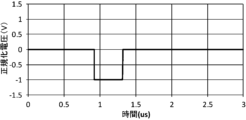
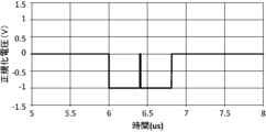
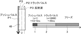
- FIG. 13 shows an example using share wave (SW).
- an ultrasonic wave (track pulse: track pulse P2) for detecting share waves is transmitted and received, and then a pause period 3 is entered.
- the thick line shown on the left side of FIG. 13 indicates the transmission of the push pulse P1 to (the piezoelectric element of) the ultrasonic transducer 48
- the one-dot chain line indicates the transmission of the track pulse P2
- the two-dot chain line indicates the track pulse P2.
- Reception of reflected wave P3 of pulse P2 is shown.
- the rest period 3 is the period until .
- strong voltage application increases the risk of depolarization, so it is necessary to quickly repolarize after the push pulse. In the repolarization process, since the probe is pulse-driven outside the band, there is almost no ultrasonic output from the element (ultrasonic transducer), and the effect on the time-average intensity is suppressed.
- the polarization of the ultrasonic transducer element can be reduced by making the transmission signal asymmetric. , but the amplitude asymmetry in the signal waveform of the transmitted signal produces a larger electric field in the direction that enhances the polarization of the piezoelectric material and a smaller electric field in the direction that opposes and degrades the polarization of the piezoelectric material. By generating it, the polarization is strengthened. Therefore, there is a problem that it is necessary to select the amplitude asymmetry of the signal waveform by the polarization of the ultrasonic transducer elements.
- the time-average intensity exceeds the above-mentioned limit value even if the polarization can be maintained.
- the work flow would be degraded depending on the rest period according to the intensity.
- An object of the present invention is to solve the above-mentioned problems of the prior art, and to inspect the state of the tissue of the observation target site, such as hardness, by generating ultrasonic waves including excitation ultrasonic waves for generating acoustic radiation pressure.
- the polarization processing of the ultrasonic transducer can be performed using the existing transmission circuit that has transmitted this transmission signal.
- Another object of the present invention is to provide an ultrasonic diagnostic system and an operating method of the ultrasonic diagnostic system which can continue examination of an observation target site while maintaining performance without lowering the workflow.
- the ultrasonic diagnostic system of the first aspect of the present invention acquires an ultrasonic image and uses acoustic radiation pressure to evaluate the hardness of a tissue to be diagnosed.
- a system for transmitting ultrasonic waves including at least excitation ultrasonic waves for vibrating tissue by acoustic radiation pressure using an ultrasonic transducer array in which a plurality of ultrasonic transducers are arranged, and
- An ultrasonic observation unit for receiving reflected waves from tissue, and a transmission signal for ultrasonic wave generation consisting of a driving pulse applied to each of the plurality of ultrasonic transducers to generate ultrasonic waves from the plurality of ultrasonic transducers.
- the ultrasonic processor device transmits ultrasonic waves and receives reflected waves, and uses the transmission circuit during the rest period of all ultrasonic transmissions after the transmission of ultrasonic waves
- a control circuit for performing polarization processing on a plurality of ultrasonic transducers that have transmitted ultrasonic waves the control circuit controlling the transmission circuit to generate a transmission signal for ultrasonic wave generation composed of drive pulses
- a transmission signal for ultrasonic wave generation that controls a transmission circuit to generate a transmission signal for polarization processing to be transmitted to the ultrasonic transducer of and generates an ultrasonic wave that includes at least an excitation ultrasonic wave that generates an acoustic radiation pressure.
- a transmission circuit After the transmission of the ultrasonic wave generation transmission signal and the polarization processing transmission signal according to the acoustic output value generated at the time of transmission of the polarization processing time is set within the rest period, and in the polarization processing time A transmission circuit transmits a transmission signal for polarization processing to at least a plurality of ultrasonic transducers that have transmitted excitation ultrasonic waves, thereby performing polarization processing.
- the control circuit calculates the acoustic output value in the polarization process in response to the user's manipulation of the tissue, and adjusts the polarization process time so that the acoustic output value is equal to or less than a preset acoustic output index value. It is preferable to control within the rest period. Further, the control circuit calculates the depolarization levels of the plurality of ultrasonic transducers generated by transmission of the ultrasonic waves from the transmission time of the ultrasonic wave generation transmission signal composed of the drive pulse, and depolarizes the calculated depolarization levels. It is preferable to calculate the acoustic output value in the treatment and control the polarization treatment time within the pause period according to the calculated acoustic output value.
- the transmission circuit transmits a first transmission signal composed of an excitation pulse as a transmission signal for ultrasonic wave generation to at least some of the plurality of ultrasonic transducers, and transmits a first transmission signal composed of excitation pulses from the plurality of ultrasonic transducers for excitation.
- An ultrasonic wave is generated and transmitted to a tissue to press and displace the tissue
- the receiving circuit receives a first received signal of a reflected wave from the tissue as a received signal
- the evaluation unit receives the first received signal.
- the stiffness of the tissue is evaluated by calculating the displacement of the tissue based on the ultrasonic image obtained from the 1st transmission signal. It is preferably a period until the start of transmission.
- the transmission circuit transmits a first transmission signal composed of an excitation pulse as a transmission signal for ultrasonic wave generation to at least some of the plurality of ultrasonic transducers, and transmits a first transmission signal for excitation from the plurality of ultrasonic transducers.
- An ultrasonic wave is generated and transmitted to the tissue to press and displace the tissue, and then a second transmission signal consisting of a detection pulse for detecting the displacement of the tissue is transmitted to generate the ultrasonic wave for detection.
- the receiving circuit receives a second received signal of the reflected wave of the ultrasonic wave for detection from the tissue as a received signal, and the evaluation unit receives an ultrasonic image obtained from the second received signal
- the rest period is the period from the end of transmission of the second transmission signal to the start of transmission of the next first transmission signal. is preferred.
- the transmission circuit transmits a first transmission signal composed of an excitation pulse as a transmission signal for ultrasonic wave generation to at least some of the plurality of ultrasonic transducers, and transmits a first transmission signal for excitation from the plurality of ultrasonic transducers.
- the ultrasonic wave for detection is generated and transmitted to the tissue in which the shear wave is generated
- the receiving circuit receives a third received signal of the reflected wave of the ultrasonic wave for detection from the tissue as a received signal
- the evaluation unit The stiffness of the tissue is evaluated by calculating the sound velocity of the shear wave based on the third received signal. It is preferably a period until the start. Further, it is preferable to have an ultrasonic endoscope including an endoscope observation section for acquiring an endoscopic image and an ultrasonic observation section.
- a method for operating an ultrasonic diagnostic system acquires an ultrasonic image and uses acoustic radiation pressure to evaluate the hardness of a tissue to be diagnosed.
- the ultrasonic diagnostic system comprises an ultrasonic observation unit having an ultrasonic transducer array in which a plurality of ultrasonic transducers are arranged; An ultrasonic wave comprising a transmission circuit that transmits a transmission signal for sound wave generation, a reception circuit that outputs reception signals of reflected waves received by a plurality of ultrasonic transducers, and an evaluation unit that evaluates tissue hardness based on the reception signals.
- a processor device for ultrasonic wave generation comprising a driving pulse applied to each of the plurality of ultrasonic transducers by controlling a transmission circuit in order to generate ultrasonic waves from the plurality of ultrasonic transducers.
- a first signal generating step of generating a signal transmitting a transmission signal for ultrasonic wave generation generated by a transmission circuit to a plurality of ultrasonic transducers; applying drive pulses to the plurality of ultrasonic transducers; a first transmission step of generating ultrasonic waves including at least excitation ultrasonic waves that generate radiation pressure and transmitting the generated ultrasonic waves to a tissue;
- the transmission circuit transmits the transmission signal for polarization processing to the plurality of ultrasonic transducers that have transmitted at least the ultrasonic waves for excitation, and performs the polarization processing. and a step.
- the acoustic output value in the polarization process is calculated in response to the user's operation on the tissue, and the polarization process time is adjusted so that the acoustic output value is equal to or less than a preset acoustic output index value. It is preferable to set within the rest period. Also, in the setting step, depolarization levels of a plurality of ultrasonic transducers generated by transmission of ultrasonic waves are calculated from transmission times of transmission signals for ultrasonic wave generation composed of drive pulses, and polarization is obtained from the calculated depolarization levels. It is preferable to calculate the acoustic output value in the treatment and control the polarization treatment time within the pause period according to the calculated acoustic output value.
- a first transmission signal composed of an excitation pulse is transmitted from the transmission circuit to at least a part of the plurality of ultrasonic transducers as a transmission signal for ultrasonic wave generation, thereby generating ultrasonic waves for excitation. is generated and transmitted to the tissue to press and displace the tissue.
- the reception circuit receives a first reception signal based on the reflected wave from the tissue as the reception signal, and the reflected wave is
- the displacement of tissue is calculated based on the ultrasonic image obtained from the first received signal by the evaluation unit to estimate the stiffness of the tissue. It is preferable that the pause period is a period from after the transmission of the first transmission signal is finished to when the transmission of the next first transmission signal is started.
- a first transmission signal composed of an excitation pulse is transmitted from the transmission circuit to at least a part of the plurality of ultrasonic transducers as a transmission signal for ultrasonic wave generation.
- a sound wave is generated and transmitted to the tissue to press and displace the tissue, and after the tissue is displaced, a transmission circuit is subsequently controlled to detect the displacement of the tissue from a detection pulse.
- a third signal generating step of generating a second transmission signal comprising a detection pulse from the transmission circuit to a plurality of ultrasonic transducers to generate ultrasonic waves for detection to generate a tissue and a second transmitting step of transmitting to, the outputting step receiving as a received signal a second received signal based on a reflected wave of the detection ultrasonic wave from the tissue by the receiving circuit, and evaluating The step is to calculate the displacement of the tissue based on the ultrasonic image obtained from the second received signal by the evaluation unit to evaluate the stiffness of the tissue, and the rest period is to transmit the second transmission signal. It is preferable that the period is from after the end to the start of transmission of the next first transmission signal.
- a first transmission signal composed of an excitation pulse is transmitted from the transmission circuit to at least a part of the plurality of ultrasonic transducers as a transmission signal for ultrasonic wave generation.
- a sound wave is generated and transmitted to the tissue to excite the tissue to generate a shear wave, and after generating the shear wave, the transmission circuit is subsequently controlled to detect the speed of sound of the shear wave.
- the output step is the receiving circuit, the third In the evaluation step, the evaluation unit calculates the sound velocity of the shear wave based on the third received signal to evaluate the stiffness of the tissue. is preferably a period from the end of transmission of the first transmission signal to the start of transmission of the next first transmission signal.
- ultrasonic waves including vibration ultrasonic waves for generating acoustic radiation pressure when performing ultrasonic elastography for examining a state such as hardness of a tissue of an observation target site.
- the existing transmission circuit that transmitted this transmission signal can be used to perform polarization processing of the ultrasonic transducer, and the workflow can be improved. It is possible to continue the examination of the observation target site while maintaining the performance without deterioration.
- the polarization processing time corresponding to the acoustic output value generated when transmitting the transmission signal for generating the ultrasonic wave and the transmission signal for performing the polarization processing can be appropriately set within the pause period,
- the polarization treatment can be appropriately performed on the ultrasonic transducer in the set polarization treatment time.
- the reception sensitivity of a plurality of ultrasonic transducers can always be kept good without deteriorating the image quality of the ultrasonic image.
- High-quality ultrasound images can be obtained.
- the polarization processing of a plurality of ultrasonic transducers is performed using an existing transmission circuit that transmits transmission signals to the ultrasonic transducers of the ultrasonic endoscope, so that the existing circuit configuration can be greatly reduced. , and the polarization processing of the ultrasonic transducer can be performed without increasing the circuit scale.
- an ultrasonic diagnostic system having a highly sensitive ultrasonic endoscope that can repolarize with an optimum waveform for the polarization even when a single crystal transducer is adopted, Further, it is possible to provide an operation method of an ultrasonic diagnostic system capable of performing repolarization with respect to polarization of a single-crystal transducer with an optimum waveform in a highly sensitive ultrasonic endoscope.
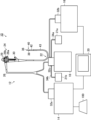
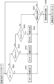
- FIG. 1 is a diagram showing a schematic configuration of an ultrasonic diagnostic system according to one embodiment of the present invention
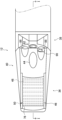
- FIG. 2 is a plan view showing the distal end portion of the insertion section of the ultrasonic endoscope shown in FIG. 1 and its surroundings
- FIG. 3 is a view showing a cross section of the distal end portion of the insertion portion of the ultrasonic endoscope shown in FIG. 2 taken along the II cross section shown in FIG. 2
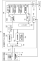
- FIG. 2 is a block diagram showing the configuration of the ultrasonic processor shown in FIG. 1
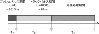
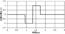
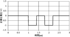
- FIG. 5 is a time chart showing transmission periods of push pulses, track pulses, and polarization drive pulses transmitted from the transmission circuit shown in FIG.
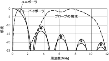
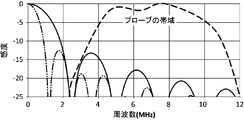
- FIG. 4 is a graph showing the relationship between the sensitivity and frequency of the drive waveform of the polarization drive pulse shown in FIG. 8A; 5 is a graph showing another example of a pulse waveform of a polarization drive pulse transmitted from the transmission circuit shown in FIG. 4; 9C is a graph showing the relationship between the sensitivity and frequency of the drive waveform of the polarization drive pulse shown in FIG. 8C.
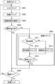
- 2 is a diagram showing the flow of diagnostic processing using the ultrasonic diagnostic system shown in FIG. 1;
- FIG. FIG. 10 is a diagram showing a procedure of a tissue hardness evaluation step in the diagnosis step shown in FIG. 9;
- FIG. 10 is a diagram showing the procedure of an image generation step in the diagnosis step shown in FIG. 9;
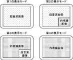
- FIG. FIG. 4 is a conceptual diagram of an example representing a display mode;
- FIG. 10 is a diagram showing an example in which share waves are performed in a conventional ultrasound system;
- FIG. 1 is a diagram showing a schematic configuration of an ultrasonic diagnostic system 10.
- the ultrasonic diagnostic system 10 uses ultrasonic waves to acquire ultrasonic images, evaluate the state of an observation target site in the body of a patient as a subject, especially the hardness of tissue, and make a diagnosis ( hereinafter also referred to as ultrasonic diagnosis).
- This ultrasonic diagnostic system 10 particularly uses acoustic radiation pressure to evaluate the tissue hardness of an observation target site (hereinafter also referred to as a diagnosis target).
- Ultrasonic elastography can be performed to evaluate the thickness and diagnose the state of the observation target site and the presence or absence of abnormalities. Ultrasonic elastography is roughly divided into strain elastography for examining tissue distortion at the observation target site and shear wave elastography for measuring the propagation velocity of shear waves in the tissue at the observation target site. Both can be implemented.
- the site to be observed is a site that is difficult to inspect from the patient's body surface side, such as the gallbladder or pancreas.
- the ultrasonic diagnostic system 10 it is possible to ultrasonically diagnose the condition and the presence or absence of an abnormality in an observation target site through the gastrointestinal tract, such as the esophagus, stomach, duodenum, small intestine, and large intestine, which are body cavities of a patient. It is possible.
- the ultrasonic diagnostic system 10 will be described as having a function of performing ultrasonic diagnosis and a function of acquiring an endoscopic image. It is also possible to have an ultrasonic diagnosis only. That is, the ultrasonic diagnostic system 10 of the present invention does not need to have an ultrasonic endoscope 12 having an ultrasonic observation unit 36 and an endoscope observation unit 38, which will be described later, and acquires endoscopic images. It does not have the endoscopic observation unit 38, the light source device 18, and the components necessary only for endoscopic observation, and can perform ultrasonic elastography and acquire an ultrasonic image. It may have the ultrasonic observation unit 36 for ultrasonic observation and components required only for ultrasonic observation.
- the ultrasonic diagnostic system 10 acquires an ultrasonic image and an endoscopic image, and as shown in FIG. It has a processor device 16 , a light source device 18 , a monitor 20 , a water supply tank 21 a , a suction pump 21 b and an operator console 100 .
- the ultrasonic endoscope 12 is an endoscope, and includes an insertion section 22 inserted into a patient's body cavity, an operation section 24 operated by an operator (user) such as a doctor or a technician, and an insertion section 22. and an ultrasonic transducer unit 46 (see FIGS. 2 and 3) attached to the distal end 40 of the.
- the operator obtains an endoscopic image of the inner wall of the patient's body cavity and an ultrasonic image of the observation target region using the functions of the ultrasonic endoscope 12 .
- an "endoscopic image” is an image obtained by photographing the inner wall of a patient's body cavity using an optical technique.
- An “ultrasonic image” is an image obtained by receiving reflected waves (echoes) of ultrasonic waves transmitted from the body cavity of a patient toward an observation target site and imaging the received signals. Note that the ultrasonic endoscope 12 will be described in detail in a later section.
- the ultrasonic processor device 14 is connected to the ultrasonic endoscope 12 via a universal cord 26 and an ultrasonic connector 32a provided at its end.
- the ultrasonic processor device 14 controls the ultrasonic transducer unit 46 of the ultrasonic endoscope 12 to generate acoustic radiation pressure for vibrating the tissue to be diagnosed.
- ultrasound is also transmitted, such as detection ultrasound for detecting tissue strain or shear waves generated in tissue.
- the ultrasonic processor 14 generates an ultrasonic image by imaging the received signal when the ultrasonic transducer unit 46 receives the reflected wave (echo) of the transmitted ultrasonic wave.
- the ultrasonic processor unit 14 will be described in detail in a later section.
- the endoscope processor device 16 is connected to the ultrasonic endoscope 12 via the universal cord 26 and an endoscope connector 32b provided at the end thereof.
- the endoscope processor device 16 acquires image data of a region adjacent to the observation target imaged by the ultrasonic endoscope 12 (more specifically, a solid-state imaging device 86, which will be described later), and performs predetermined processing on the acquired image data. Image processing is performed to generate an endoscopic image.
- the "adjacent site to be observed" is a portion of the inner wall of the patient's body cavity that is adjacent to the site to be observed.
- the ultrasound processor 14 and the endoscope processor 16 are composed of two separate devices (computers). However, the present invention is not limited to this, and both the ultrasound processor device 14 and the endoscope processor device 16 may be configured by one device.
- the light source device 18 is connected to the ultrasonic endoscope 12 via the universal cord 26 and a light source connector 32c provided at its end.
- the light source device 18 emits white light or specific wavelength light composed of the three primary colors of red, green, and blue light when imaging a site adjacent to the observation target using the ultrasonic endoscope 12 .
- the light emitted by the light source device 18 propagates through the ultrasonic endoscope 12 through a light guide (not shown) included in the universal cord 26, and passes through the ultrasonic endoscope 12 (detailedly, an illumination window 88, which will be described later). emitted from As a result, the adjacent site to be observed is illuminated by the light from the light source device 18 .
- the monitor 20 is connected to the ultrasound processor device 14 and the endoscope processor device 16, and displays the ultrasound images generated by the ultrasound processor device 14 and the ultrasound images generated by the endoscope processor device 16.
- Display endoscopic images As a display method for the ultrasonic image and the endoscopic image, a method in which one of the images is switched and displayed on the monitor 20, or a method in which both images are displayed at the same time may be used. Display modes for ultrasonic images and endoscopic images will be described later. In this embodiment, an ultrasonic image and an endoscopic image are displayed on the single monitor 20, but a monitor for displaying the ultrasonic image and a monitor for displaying the endoscopic image are provided separately. good too. Also, the ultrasonic image and the endoscopic image may be displayed in a display form other than the monitor 20, for example, in a display form of a terminal carried by the operator.
- the operator console 100 is a device provided for the operator to input necessary information for ultrasonic diagnosis and to instruct the ultrasonic processor device 14 to start ultrasonic diagnosis.
- the operator console 100 includes, for example, a keyboard, mouse, trackball, touch pad, touch panel, and the like.
- the CPU (control circuit) 152 (see FIG. 4) of the ultrasonic processor device 14 controls each part of the device (for example, a receiving circuit 142 and a transmitting circuit 144 which will be described later) in accordance with the contents of the operation. Control.
- the operator before starting ultrasonic diagnosis, the operator provides examination information (for example, examination order information including date and order number, patient information including patient ID and patient name, and , inspection content and inspection target site information) are input at the console 100 .
- examination information for example, examination order information including date and order number, patient information including patient ID and patient name, and , inspection content and inspection target site information
- the CPU 152 of the ultrasonic processor unit 14 executes ultrasonic diagnosis based on the inputted examination information.
- Each section of the ultrasonic processor unit 14 is controlled.
- the operator can set various control parameters at the console 100 when performing ultrasonic diagnosis. Control parameters include, for example, the result of selection between live mode and freeze mode, the set value of display depth (depth), and the result of selection of ultrasonic image generation mode.
- the "live mode” is a mode in which ultrasonic images (moving images) obtained at a predetermined frame rate are sequentially displayed (real-time display).
- the “freeze mode” is a mode in which a one-frame image (still image) of an ultrasound image (moving image) generated in the past is read from the cine memory 150 described later and displayed.
- the B mode is a mode for displaying a tomographic image by converting the amplitude of an ultrasonic echo into luminance.
- the CF mode is a mode in which average blood flow velocity, flow fluctuation, flow signal intensity, flow power, etc. are mapped in various colors and displayed superimposed on a B-mode image.
- the PW mode is a mode for displaying the velocity of an ultrasonic echo source (for example, blood flow velocity) detected based on the transmission and reception of pulse waves.
- ultrasonic image generation mode is merely an example, and modes other than the three types of modes described above, such as A (Amplitude) mode, M (Motion) mode, contrast mode, etc., may be further included. However, a mode for obtaining Doppler images may also be included.
- FIG. 2 is an enlarged plan view showing the distal end portion of the insertion portion 22 of the ultrasonic endoscope 12 and its surroundings.
- FIG. 3 is a cross-sectional view showing a cross section of the distal end portion 40 of the insertion portion 22 of the ultrasonic endoscope 12 taken along the II cross section shown in FIG.
- the ultrasonic endoscope 12 has the insertion portion 22 and the operation portion 24 as described above.
- the insertion section 22 includes a distal end portion 40, a curved portion 42, and a flexible portion 43 in order from the distal end side (free end side), as shown in FIG.
- the distal end portion 40 is provided with an ultrasonic observation section 36 and an endoscope observation section 38 as shown in FIG.
- an ultrasonic transducer unit 46 having a plurality of ultrasonic transducers 48 is arranged in the ultrasonic observation section 36 .
- the treatment instrument lead-out port 44 serves as an outlet for a treatment instrument (not shown) such as forceps, a puncture needle, or a high-frequency scalpel.
- the treatment instrument lead-out port 44 also serves as a suction port for sucking substances such as blood and body waste.
- the bending portion 42 is a portion that is continuous with the proximal end side (the side opposite to the side where the ultrasonic transducer unit 46 is provided) from the distal end portion 40, and is bendable.
- the flexible portion 43 is a portion that connects the bending portion 42 and the operation portion 24 , has flexibility, and is provided in an elongated state.
- a plurality of ducts for air/water supply and a plurality of ducts for suction are formed inside each of the insertion portion 22 and the operation portion 24, a treatment instrument channel 45 is formed, one end of which communicates with the treatment instrument outlet 44.
- the ultrasonic observation section 36, the endoscope observation section 38, the water supply tank 21a and the suction pump 21b, and the operation section 24 will be described in detail.
- the ultrasonic observation section 36 is a section provided for acquiring an ultrasonic image, and is arranged on the distal end side of the distal section 40 of the insertion section 22 .
- the ultrasonic observation unit 36 includes an ultrasonic transducer unit 46, a plurality of coaxial cables 56, and an FPC (Flexible Printed Circuit) 60, as shown in FIG.
- the ultrasonic transducer unit 46 corresponds to an ultrasonic probe (probe), and ultrasonic waves are generated using an ultrasonic transducer array 50 in which a plurality of ultrasonic transducers 48, which will be described later, are arranged in a patient's body cavity.
- the ultrasonic transducer unit 46 is of a convex type, and transmits ultrasonic waves radially (in an arc).
- the type (model) of the ultrasonic transducer unit 46 is not particularly limited to this, and other types may be used as long as they can transmit and receive ultrasonic waves, such as sector type, linear type and radial type. etc.
- the ultrasonic transducer unit 46 is configured by laminating a backing material layer 54, an ultrasonic transducer array 50, an acoustic matching layer 74, and an acoustic lens 76, as shown in FIG.
- the ultrasonic transducer array 50 may be configured by arranging a plurality of ultrasonic transducers 48 in a two-dimensional array.
- Each of the N ultrasonic transducers 48 is configured by arranging electrodes on both sides of a single-crystal transducer, which is a piezoelectric element.
- Crystal lithium niobate, lead magnesium niobate (PMN), lead magnesium niobate-lead titanate (PMN-PT), lead zinc niobate (PZN), lead zinc niobate-titanate Any one of lead (PZN-PT), lead indium niobate (PIN), lead titanate (PT), lithium tantalate, langasite, and zinc oxide is used.
- the electrodes consist of individual electrodes (not shown) individually provided for each of the plurality of ultrasonic transducers 48 and a transducer ground (not shown) common to the plurality of ultrasonic transducers 48 .
- the electrodes are also electrically connected to the ultrasound processor unit 14 via the coaxial cable 56 and the FPC 60 .
- the ultrasonic transducer 48 needs to be driven (vibrated) at a relatively high frequency of 7 MHz to 8 MHz for the purpose of acquiring an ultrasonic image of the body cavity of the patient. Therefore, the thickness of the piezoelectric element forming the ultrasonic transducer 48 is designed to be relatively thin, for example, 75 ⁇ m to 125 ⁇ m, preferably 90 ⁇ m to 110 ⁇ m.
- a diagnostic drive pulse which is a pulsed drive voltage, is supplied to each ultrasonic transducer 48 as an input signal (transmission signal) from the ultrasonic processor 14 through the coaxial cable 56 .
- the piezoelectric element expands and contracts to drive (vibrate) the ultrasonic transducer 48 .
- a pulsed ultrasonic wave is output from the ultrasonic transducer 48 .
- the amplitude of the ultrasonic waves output from the ultrasonic transducer 48 has a magnitude corresponding to the intensity (output intensity) when the ultrasonic transducer 48 outputs the ultrasonic waves.
- the output intensity is defined as the magnitude of the sound pressure of the ultrasonic waves output from the ultrasonic transducer 48 .
- the ultrasonic transducer 48 transmits an excitation pulse such as a push pulse of strong ultrasonic output for performing ultrasonic elastography as a drive pulse, and emits an excitation ultrasonic wave.
- an excitation pulse such as a push pulse of strong ultrasonic output for performing ultrasonic elastography as a drive pulse
- an excitation ultrasonic wave such as a push pulse of strong ultrasonic output for performing ultrasonic elastography as a drive pulse
- shear elastic wave which is a transverse wave generated by vibration of the tissue of the observation target site by the vibration ultrasonic wave
- shear A detection pulse such as a track pulse for detecting a wave (share wave) is transmitted to generate an ultrasonic wave for detection.
- each ultrasonic transducer 48 When each ultrasonic transducer 48 receives a reflected ultrasonic wave (echo), it vibrates (drives) accordingly, and the piezoelectric element of each ultrasonic transducer 48 generates an electric signal.
- the reflected waves received by each ultrasonic transducer 48 are directly transmitted from the tissue of the observation target site that has been pressed and displaced by receiving the excitation ultrasonic waves generated by the excitation pulse. It may be a reflected wave that is reflected, or a detection ultrasonic wave generated by a detection pulse for detecting the displacement (distortion) of the tissue of the observation target site that has been pressed and displaced by receiving the excitation ultrasonic wave.
- each ultrasonic transducer 48 It may be a reflected wave, or a reflected wave of ultrasonic waves for detection for detecting shear waves (shear waves) generated in the tissue of the observation target site that is vibrated by receiving the ultrasonic waves for excitation.
- An electrical signal generated by each ultrasonic transducer 48 is output from each ultrasonic transducer 48 toward the ultrasonic processor 14 as an ultrasonic reception signal.
- the magnitude (voltage value) of the electric signal output from the ultrasonic transducer 48 corresponds to the reception sensitivity when the ultrasonic transducer 48 receives ultrasonic waves.
- the reception sensitivity is defined as the ratio of the amplitude of the electric signal output by the ultrasonic transducer 48 after receiving the ultrasonic wave to the amplitude of the ultrasonic wave transmitted by the ultrasonic transducer 48 .
- an electronic switch such as a multiplexer 140
- the ultrasonic waves output from the m drive target transducers are immediately synthesized, and the synthesized wave (ultrasonic beam) is transmitted toward the observation target region. After that, each of the m drive target transducers receives the ultrasonic waves (echoes) reflected by the observation target site, and outputs an electric signal (reception signal) corresponding to the reception sensitivity at that time.
- the positions of the driven transducers in the N ultrasonic transducers 48 are changed one by one (one This is repeated by shifting the ultrasonic transducers 48 at a time. More specifically, the above series of steps are performed from the m number of driven transducers on both sides of the ultrasonic transducer 48 positioned at one end of the N ultrasonic transducers 48. be started. The series of steps described above is repeated every time the position of the transducer to be driven shifts due to switching of the aperture channel by the multiplexer 140 . Ultimately, the series of steps described above is performed up to the m number of driven transducers on both sides of the ultrasonic transducer 48 located at the other end of the N ultrasonic transducers 48. This is repeated N times in total.
- the backing material layer 54 supports each ultrasonic transducer 48 of the ultrasonic transducer array 50 from the back side. In addition, the backing material layer 54 attenuates the ultrasonic waves propagated to the backing material layer 54 side among the ultrasonic waves emitted from the ultrasonic transducer 48 or the ultrasonic waves (echoes) reflected at the observation target site. have a function.
- the backing material is made of a rigid material such as hard rubber, and an ultrasonic damping material (ferrite, ceramics, etc.) is added as necessary.
- the acoustic matching layer 74 is overlaid on the ultrasound transducer array 50 and provided for acoustic impedance matching between the patient's body and the ultrasound transducers 48 .
- the acoustic matching layer 74 By providing the acoustic matching layer 74, it is possible to increase the transmittance of ultrasonic waves.
- the material of the acoustic matching layer 74 various organic materials having acoustic impedance values closer to those of the patient's human body than the piezoelectric element of the ultrasonic transducer 48 can be used.
- Specific examples of materials for the acoustic matching layer 74 include epoxy resin, silicon rubber, polyimide, and polyethylene.
- the acoustic lens 76 superimposed on the acoustic matching layer 74 is for converging the ultrasonic waves emitted from the ultrasonic transducer array 50 toward the site to be observed.
- the acoustic lens 76 is made of, for example, silicon-based resin (millable type silicon rubber (HTV rubber), liquid silicon rubber (RTV rubber), etc.), butadiene-based resin, polyurethane-based resin, or the like. , alumina or silica are mixed.
- the FPC 60 is electrically connected to electrodes provided on each ultrasonic transducer 48 .
- Each of the plurality of coaxial cables 56 is wired to the FPC 60 at one end thereof.
- each of the plurality of coaxial cables 56 is connected at the other end (the side opposite to the FPC 60 side). It is electrically connected to the ultrasonic processor device 14 .
- the ultrasonic endoscope 12 includes an endoscope-side memory 58 (see FIG. 4).
- the endoscope-side memory 58 may store driving times of the plurality of ultrasonic transducers 48 during ultrasonic diagnosis. Strictly speaking, the endoscope-side memory 58 may store the cumulative driving time of the drive target transducer among the plurality of ultrasonic transducers 48 .
- the ultrasonic transducers 48 whose cumulative drive time exceeds a predetermined value may be removed from the transducers to be driven, and the removed ultrasonic transducers 48 may be subjected to polarization processing.
- the ultrasonic diagnosis is performed, that is, the period from the start to the end of acquisition of an ultrasonic image (moving image) (more specifically, the ultrasonic diagnosis is performed in live mode).
- the time during which the drive voltage is supplied to the driven vibrator may be used as the cumulative drive time.
- the CPU 152 of the ultrasonic processor device 14 accesses the endoscope-side memory 58, and the accumulated data stored in the endoscope-side memory 58 You can also read the drive time. Further, the CPU 152 of the ultrasound processor 14 rewrites the cumulative driving time stored in the endoscope-side memory 58 to the default value, or renews the cumulative driving time when the cumulative driving time changes due to the implementation of ultrasonic diagnosis. It may be updated to the cumulative driving time of
- the endoscopic observation section 38 is a portion provided for acquiring an endoscopic image, and is arranged closer to the proximal side than the ultrasonic observation section 36 at the distal end portion 40 of the insertion section 22 .
- the endoscope observation section 38 is composed of an observation window 82, an objective lens 84, a solid-state imaging device 86, an illumination window 88, a cleaning nozzle 90, a wiring cable 92, and the like, as shown in FIGS.
- the observation window 82 is attached to the distal end portion 40 of the insertion portion 22 so as to be inclined with respect to the axial direction (longitudinal axis direction of the insertion portion 22).
- the light incident through the observation window 82 and reflected by a portion adjacent to the observation object is imaged on the imaging surface of the solid-state imaging device 86 by the objective lens 84 .
- the solid-state imaging device 86 photoelectrically converts the reflected light from the observation target adjacent region that has passed through the observation window 82 and the objective lens 84 and is imaged on the imaging surface, and outputs an imaging signal.
- a CCD Charge Coupled Device
- CMOS Complementary Metal Oxide Semiconductor
- a captured image signal output by the solid-state imaging device 86 is transmitted to the endoscope processor device 16 via the universal cord 26 via a wiring cable 92 extending from the insertion section 22 to the operation section 24 .
- the illumination windows 88 are provided on both sides of the observation window 82 .
- An output end of a light guide (not shown) is connected to the illumination window 88 .
- the light guide extends from the insertion section 22 to the operation section 24 and its incident end is connected to the light source device 18 connected via the universal cord 26 .
- the illumination light emitted by the light source device 18 travels through the light guide and is irradiated from the illumination window 88 toward the site adjacent to the observation target.
- the cleaning nozzle 90 is a jet hole formed in the distal end portion 40 of the insertion portion 22 for cleaning the surfaces of the observation window 82 and the illumination window 88 . and is jetted toward the illumination window 88 .
- the cleaning liquid jetted from the cleaning nozzle 90 is water, especially deaerated water.
- the cleaning liquid is not particularly limited, and may be another liquid such as normal water (non-deaerated water).
- the water supply tank 21a is a tank for storing degassed water, and is connected to the light source connector 32c by an air/water supply tube 34a.
- the degassed water is used as the cleaning liquid jetted from the cleaning nozzle 90 .
- the suction pump 21b sucks the aspirate (including the degassed water supplied for washing) inside the body cavity through the treatment instrument outlet 44 .
- the suction pump 21b is connected to the light source connector 32c through a suction tube 34b.
- the ultrasonic diagnostic system 10 may include an air supply pump or the like that supplies air to a predetermined air supply destination.
- a treatment instrument channel 45 and an air/water supply conduit are provided in the insertion section 22 and the operation section 24 .
- the treatment instrument channel 45 communicates between the treatment instrument insertion port 30 and the treatment instrument outlet port 44 provided in the operation section 24 .
- the treatment instrument channel 45 is connected to a suction button 28b provided on the operation section 24 .
- the suction button 28b is connected to the treatment instrument channel 45 and also to the suction pump 21b.
- One end of the air/water supply conduit communicates with the cleaning nozzle 90 , and the other end thereof is connected to an air/water supply button 28 a provided on the operation unit 24 .
- the air/water supply button 28a is connected to the water supply tank 21a in addition to the air/water supply conduit.
- the operation unit 24 is a portion operated by the operator at the start of ultrasonic diagnosis, during diagnosis, at the end of diagnosis, etc., and one end of a universal cord 26 is connected to one end of the operation unit 24 .
- the operation unit 24 also has an air/water supply button 28a, a suction button 28b, a pair of angle knobs 29, and a treatment instrument insertion opening (forceps opening) 30, as shown in FIG.
- the bending portion 42 is remotely operated to bend and deform. This deformation operation enables the distal end portion 40 of the insertion portion 22 provided with the ultrasonic observation portion 36 and the endoscope observation portion 38 to be directed in a desired direction.
- the treatment instrument insertion port 30 is a hole formed for inserting a treatment instrument (not shown) such as forceps, and communicates with the treatment instrument outlet 44 via a treatment instrument channel 45 .
- the treatment instrument inserted into the treatment instrument insertion port 30 is introduced into the body cavity from the treatment instrument outlet port 44 after passing through the treatment instrument channel 45 .
- the air/water supply button 28a and the suction button 28b are two-stage switching push buttons, and are operated to switch opening and closing of the channels provided inside the insertion section 22 and the operation section 24, respectively.
- the ultrasonic processor device 14 causes the ultrasonic transducer unit 46 to transmit and receive ultrasonic waves, and converts the received signal output by the ultrasonic transducer 48 (more specifically, the element to be driven) into an image when receiving the ultrasonic waves. Generate an image.
- the ultrasound processor device 14 also displays the generated ultrasound image on the monitor 20 . Furthermore, in this embodiment, the ultrasound processor device 14 supplies a polarization voltage to a polarization target transducer among the N ultrasound transducers 48 to polarize the polarization target transducer.
- the ultrasonic transducer 48 that has been depolarized by repeated ultrasonic diagnosis can be repolarized, thereby increasing the reception sensitivity of the ultrasonic transducer 48 to ultrasonic waves to a favorable level. It is possible to recover up to
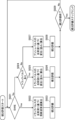
- the ultrasound processor device 14 includes a multiplexer 140, a receiving circuit 142, a transmitting circuit 144, an A/D converter 146, an ASIC (Application Specific Integrated Circuit) 148, a cine memory 150, and a CPU (Central Processing Unit). 152, and a DSC (Digital Scan Converter) 154.
- the receiving circuit 142 and the transmitting circuit 144 are electrically connected to the ultrasonic transducer array 50 of the ultrasonic endoscope 12 .
- the multiplexer 140 selects up to m number of transducers to be driven from among the N number of ultrasonic transducers 48 and opens the channels thereof.
- the transmission circuit 144 consists of FPGA (field programmable gate array), pulser (pulse generation circuit 158), SW (switch), etc., and is connected to MUX (multiplexer 140). Note that an ASIC (application specific integrated circuit) may be used instead of the FPGA.
- the transmission circuit 144 applies a driving voltage for transmitting ultrasonic waves to the transducers to be driven selected by the multiplexer 140 according to control signals sent from the CPU 152.
- the drive voltage is a pulsed voltage signal (transmission signal) and is applied to the electrodes of the vibrator to be driven via the universal cord 26 and coaxial cable 56 .
- the transmission circuit 144 has a pulse generation circuit 158 that generates a transmission signal based on a control signal. Under the control of the CPU 152, the pulse generation circuit 158 is used to drive a plurality of ultrasonic transducers 48 to generate ultrasonic waves. A transmission signal for generating sound waves is generated and supplied to a plurality of ultrasonic transducers 48 .
- the transmission circuit 144 uses the pulse generation circuit 158 to generate an ultrasonic wave generation transmission signal having a driving voltage for ultrasonic diagnosis.
- the pulse generation circuit 158 of the transmission circuit 144 generates an excitation pulse for generating an excitation ultrasonic wave in the ultrasonic transducer 48 as a transmission signal for ultrasonic wave generation, That is, it is necessary to generate a first transmission signal consisting of push pulses.
- the pulse generation circuit 158 is used as an ultrasonic wave generation transmission signal for generating detection ultrasonic waves in the ultrasonic transducer 48 to detect distortion caused in the tissue to be diagnosed by excitation ultrasonic waves by push pulses. or a third transmission signal consisting of a detection pulse for measuring the propagation velocity of the shear wave generated in the tissue to be diagnosed by the excitation ultrasound due to the push pulse.
- a third transmission signal consisting of a detection pulse for measuring the propagation velocity of the shear wave generated in the tissue to be diagnosed by the excitation ultrasound due to the push pulse.
- the same pulse generation circuit 158 as used for generating the transmission signal for ultrasonic wave generation is used to generate the transmission signal for polarization processing having the voltage for polarization for performing the polarization processing.
- the ultrasonic transducer 48 receives a reflected wave (echo) from the distorted tissue with respect to the excitation ultrasonic wave and generates a first received signal.
- the second transmission signal and the third transmission signal each composed of a detection pulse are transmitted to the ultrasonic transducer 48, the ultrasonic waves for detection generated from the ultrasonic transducer 48 are applied to the distorted tissue.
- the shear waves are transmitted to the tissue where the shear wave is generated, and the reflected wave (echo) from the tissue where the strain is generated and the reflected wave corresponding to the shear wave from the tissue where the shear wave is generated ( echoes) are received by the ultrasonic transducer 48 to generate a second received signal and a third received signal.
- the receiving circuit 142 is a circuit for receiving an electric signal output from the transducer to be driven that has received an ultrasonic wave (echo), that is, a received signal.
- the receiving circuit 142 receives the first received signal of the reflected wave of the ultrasonic wave for excitation from the distorted tissue, which is generated from the ultrasonic transducer 48, and the ultrasonic wave for detection from the distorted tissue.
- a second received signal of the reflected wave or a third received signal of the reflected wave of the detection ultrasound from the tissue in which the shear wave was generated is received.
- the receiving circuit 142 amplifies the received signal received from the ultrasonic transducer 48 according to the control signal sent from the CPU 152 and transfers the amplified signal to the A/D converter 146 .
- the A/D converter 146 is connected to the receiving circuit 142 , converts the received signal received from the receiving circuit 142 from an analog signal to a digital signal, and outputs the converted digital signal to the ASIC 148 .
- the ASIC 148 is connected to the A/D converter 146, and as shown in FIG. , and the memory controller 151 .
- hardware circuits such as the ASIC 148 perform the functions described above (specifically, the phase matching unit 160, the B mode image generation unit 162, the PW mode image generation unit 164, the CF mode image generation unit 166, Although the evaluation unit 168 and the memory controller 151) are implemented, the present invention is not limited to this.
- the above functions may be realized by cooperation between a central processing unit (CPU) and software (computer program) for executing various data processing.
- the phase matching unit 160 performs a process of applying a delay time to the received signal (received data) digitized by the A/D converter 146 and performing phasing addition (adding after matching the phase of the received data). do.
- a sound ray signal in which the focus of the ultrasonic echo is narrowed is generated by the phasing and addition processing.
- the B-mode image generator 162, the PW-mode image generator 164, and the CF-mode image generator 166 drive one of the plurality of ultrasonic transducers 48 when the ultrasonic transducer unit 46 receives an ultrasonic wave (echo).
- An ultrasonic image is generated based on the electrical signal output by the target transducer (strictly speaking, the audio signal generated by phasing and adding the received data).
- the B-mode image generation unit 162 is an image generation unit that generates a B-mode image, which is a tomographic image of the inside (inside the body cavity) of the patient.
- the B-mode image generator 162 corrects the attenuation caused by the propagation distance according to the depth of the reflection position of the ultrasonic waves by STC (Sensitivity Time Gain Control) for the sequentially generated sound ray signals.
- the B-mode image generation unit 162 also performs envelope detection processing and log (logarithmic) compression processing on the corrected sound ray signal to generate a B-mode image (image signal).
- the PW mode image generator 164 is an image generator that generates an image that displays the blood flow velocity in a predetermined direction.
- the PW mode image generation unit 164 extracts frequency components by performing a fast Fourier transform on a plurality of sound ray signals in the same direction among the sound ray signals sequentially generated by the phase matching unit 160 . After that, the PW mode image generator 164 calculates the blood flow velocity from the extracted frequency components, and generates a PW mode image (image signal) displaying the calculated blood flow velocity.
- the CF mode image generation unit 166 is an image generation unit that generates an image that displays blood flow information in a predetermined direction.
- the CF-mode image generating unit 166 generates an image signal indicating information about blood flow by obtaining the autocorrelation of a plurality of sound ray signals in the same direction among the sound ray signals sequentially generated by the phase matching unit 160. . After that, the CF-mode image generation unit 166 generates a CF-mode image (image signal ).
- the evaluation unit 168 evaluates an electric signal (strictly speaking, received data). The hardness of the tissue to be diagnosed is evaluated based on the audio signal generated by delaying and adding the . The evaluation unit 168 evaluates the received signal from the first received signal when the receiving circuit 142 receives the first received signal and from the second received signal when the second received signal is received. Based on a sound wave image, for example, a B-mode ultrasonic image generated by the B-mode image generation unit 162, the displacement (distortion) of the tissue to be diagnosed is calculated to evaluate the stiffness of the tissue.
- a sound wave image for example, a B-mode ultrasonic image generated by the B-mode image generation unit 162
- the evaluation unit 168 calculates the sound velocity of the shear wave generated in the tissue to be diagnosed based on the third reception signal, and calculates the hardness of the tissue. Evaluate These hardness evaluations can be performed with reference to the following URL. https://www.jstage.jst.go.jp/article/mit/32/2/32_75/_pdf
- the memory controller 151 stores the image signal generated by the B-mode image generator 162 , PW-mode image generator 164 or CF-mode image generator 166 in the cine memory 150 .
- the DSC 154 is connected to the ASIC 148, and converts the image signal generated by the B-mode image generator 162, PW-mode image generator 164, or CF-mode image generator 166 into an image signal conforming to a normal television signal scanning method. (raster conversion), and the image signal is output to the monitor 20 after being subjected to various necessary image processing such as gradation processing.
- the cine memory 150 has a capacity for accumulating image signals for one frame or several frames.
- the image signal generated by the ASIC 148 is output to the DSC 154 and also stored in the cine memory 150 by the memory controller 151 .
- the memory controller 151 reads the image signal stored in the cine memory 150 and outputs it to the DSC 154 .
- an ultrasonic image (still image) based on the image signal read from the cine-memory 150 is displayed on the monitor 20 .
- the CPU 152 functions as a control section (control circuit) that controls each section of the ultrasonic processor device 14, and is connected to the receiving circuit 142, the transmitting circuit 144, the A/D converter 146, and the ASIC 148 to control these devices. Control. More specifically, the CPU 152 is connected to the operator console 100 and controls each section of the ultrasonic processor device 14 according to examination information, control parameters, and the like input from the operator console 100 . Further, when the ultrasonic endoscope 12 is connected to the ultrasonic processor device 14 via the ultrasonic connector 32a, the CPU 152 automatically recognizes the ultrasonic endoscope 12 by a method such as PnP (Plug and Play). do. After that, the CPU 152 can also access the endoscope-side memory 58 of the ultrasonic endoscope 12 and read the cumulative driving time stored in the endoscope-side memory 58 .
- PnP Plug and Play
- the CPU 152 accesses the endoscope-side memory 58 at the end of the ultrasonic diagnosis, and changes the cumulative driving time stored in the endoscope-side memory 58 to the time required for the immediately preceding ultrasonic diagnosis. It may be updated to the added value.
- the ultrasonic endoscope 12 stores the accumulated driving time, but the present invention is not limited to this. It may be stored for each scope 12 .
- an excitation pulse (push pulse) is generated in the pulse generation circuit 158 during the execution of ultrasonic diagnosis, and a plurality of ultrasonic waves of the ultrasonic transducer array 50 are transmitted from the transmission circuit 144.
- the attenuation spatial peak time average intensity (hereinafter simply referred to as time average intensity) Ispta. ⁇ or because the time-average intensity Ispta. ⁇ exceeds or is likely to exceed the US FDA limit of 720 mW/ cm2 .
- a rest period (freeze period) was provided.
- the pulse generating circuit 158 continues to detect pulses ( hereinafter also referred to as a track pulse) is generated and supplied from the transmission circuit 144 to each of the plurality of ultrasonic transducers 48 to output ultrasonic waves for detection toward the tissue, the time average intensity Ispta. ⁇ further increases. As described above, a pause period (freeze period) is provided after the ultrasonic wave for detection is output.
- the attenuation spatial peak time average intensity Ispta Since it exceeds or is likely to exceed cm 2 , it is necessary to provide a pause period (freeze period), resulting in a drop in the frame rate of ultrasonic diagnosis.
- the transmission circuit 144 (pulse generation circuit 158) is controlled to generate a polarization driving pulse, which is a pulsed driving voltage, during the pause period in order to reduce the time-average intensity Ispta. ⁇ . are generated and supplied to each of the plurality of ultrasonic transducers 48 of the ultrasonic transducer array 50 to perform polarization processing of each ultrasonic transducer 48 .
- a polarization driving pulse which is a pulsed driving voltage
- the CPU 152 is connected to the pulse generation circuit 158 of the transmission circuit 144, and generates an excitation pulse (push pulse) in the pulse generation circuit 158 during the period of ultrasonic diagnosis, and transmits the pulse to the transmission circuit.
- 144 to each of the plurality of ultrasonic transducers 48 of the ultrasonic transducer array 50 to generate strong excitation ultrasonic waves in a short period of time and output them to the tissue to be diagnosed, or push pulses.
- a detection pulse (track pulse) is generated in the pulse generation circuit 158, and supplied to the plurality of ultrasonic transducers 48 from the transmission circuit 144, respectively, and the ultrasonic wave for excitation is supplied to the plurality of ultrasonic transducers 48.
- the transmission circuit 144 (pulse generation circuit 158) is controlled to generate a polarization drive pulse, which is a pulsed drive voltage, to generate ultrasonic vibration.
- a polarization drive pulse which is a pulsed drive voltage
- the driving pulse for polarization is a push pulse for vibrating and displacing the tissue to be diagnosed or generating a shear wave, and a strain due to the displacement of the tissue or for detecting a shear wave. or a diagnostic drive pulse such as an image drive pulse for acquiring an ultrasonic image of a diagnostic target.
- the transmission circuit 144 has the same circuit configuration as an existing transmission circuit that does not have a new circuit configuration for generating the polarization drive pulse.
- the transmission circuit 144 transmits at least two drive voltages: the drive voltage for hardness evaluation of the push pulse and the track pulse, the drive voltage for image of the drive pulse for image, and the drive voltage for polarization of the drive pulse for polarization.
- the polarization drive voltage is preferably set to a voltage higher than the hardness evaluation drive voltage and the image drive voltage, and is set to a higher voltage within the settable voltage range. It is more preferable that the voltage is set to the upper limit voltage.
- the polarization drive pulse main lobe is a drive pulse in a frequency band different from the probe frequency band of diagnostic drive pulses such as push pulses, track pulses, and image drive pulses.
- the driving voltage applied to the ultrasonic transducer 48 during the polarization process is the same as the diagnostic drive voltage applied to the ultrasonic transducer 48 during evaluation of tissue hardness and ultrasonic diagnosis such as acquisition of an ultrasonic image. Unlike voltage, it can be said to be a higher voltage.
- the polarization drive pulse wave applied to the ultrasonic transducer 48 during the polarization process is applied to the ultrasonic transducer 48 during evaluation of tissue hardness and ultrasonic diagnosis such as acquisition of an ultrasonic image. It is generated by the same transmission circuit 144 as the push pulse wave, the track pulse wave, and the diagnostic drive pulse wave such as the image drive pulse wave.
- the drive pulse wave has a different polarization drive voltage within the same settable voltage range as the drive pulse wave and has a frequency different from the probe frequency band for ultrasonic diagnosis.
- the polarization drive pulse has a frequency different from the probe frequency band of the diagnostic drive pulse.
- the ultrasonic transducer 48 undergoing polarization processing hardly outputs ultrasonic waves, and it can be said that the influence on the spatial peak time average intensity is suppressed to a low level.
- the present invention has an existing transmission circuit configuration, uses the same transmission circuit 144 for driving pulse output as that for ultrasonic diagnosis, and uses the same settable voltage range as the diagnostic driving pulse for ultrasonic diagnosis. and a driving pulse for polarization with a frequency different from the probe frequency band, and rest after application of the push pulse when evaluating the hardness of the tissue, or after application of the push pulse and subsequent application of the track pulse During this period, the polarization processing of the ultrasonic transducer 48 of the ultrasonic endoscope 12 is performed.
- the drive voltage for polarization (voltage value or potential) of the drive pulse for polarization is within the settable voltage range of the transmission circuit 144, and the ultrasonic endoscope connected to the ultrasonic processor device 14 12 (specifically, the thickness and material of the ultrasonic transducer 48), the CPU 152 sets an appropriate value that satisfies the conditions for obtaining the effect of repolarization.
- the time during which the drive voltage for the polarization drive pulse is supplied is the time within the pause period in which no drive pulse is applied after the push pulse is transmitted, or after the push pulse is transmitted and the track pulse is subsequently transmitted.
- the CPU 152 sets an appropriate value that satisfies the conditions for obtaining the effect of repolarization according to the cumulative drive time and the specifications of the ultrasonic transducer 48 (more specifically, the thickness and material of the ultrasonic transducer 48).
- the CPU 152 performs polarization processing based on the values of the attenuated spatial peak temporal average acoustic output and the attenuation spatial peak temporal average intensity, or further, based on the accumulated driving time and the set value.
- This push pulse period Tx is the same as the push pulse transmission period 1 shown in FIG.
- This track pulse period Ty is the same as the track pulse transmission/reception period 2 shown in FIG.
- polarization processing period Tz The time from the start of polarization processing (transmission of a driving pulse for polarization) to the start of transmission of the next push pulse is defined as a polarization processing period Tz, which is a drive pulse rest period during which no push pulse or track pulse is transmitted. be.
- This polarization processing period Tz is the same as the rest period 3 shown in FIG. 13 in the sense that it is the rest period of the drive pulse.
- the polarization processing period Tz there are cases where the polarization processing is not performed during the entire period. is the sum of the complete pause time during which no polarization processing is performed due to the transmission of .
- the acoustic output value generated in the ultrasonic transducer 48 when the push pulse is transmitted to the plurality of ultrasonic transducers 48 of the ultrasonic transducer unit 46 that is, the attenuation spatial peak time average
- the value of the acoustic output be X (mJ/cm 2 ).
- the attenuated spatial peak time average acoustic output represents the energy of ultrasonic waves radiated from the plurality of ultrasonic transducers 48 of the ultrasonic transducer unit 46 to a unit area perpendicular to the traveling direction of the ultrasonic waves within a unit time.
- Y (mJ/cm 2 ) be the value of the damped spatial peak time average acoustic output generated in the ultrasonic transducer 48 when the track pulse is transmitted to the ultrasonic transducer 48 in the track pulse period Ty.
- the value of the attenuation spatial peak time average acoustic output (hereinafter simply referred to as time average acoustic output) generated in the ultrasonic transducer 48 during the polarization processing of the ultrasonic transducer 48 is Z (mJ/cm 2 ).
- the total attenuation spatial peak time average intensity Ispta. ⁇ (mW/cm 2 ) is calculated by the following formula (1).
- Ispta. ⁇ (X+Y+Z)/(Tx+Ty+Tz) (1)
- the CPU 152 calculates the time-average intensity Ispta. ⁇ based on the values X, Y, and Z of the time-average acoustic output.
- the CPU 152 performs specific processing according to the acoustic output values X, Y, and Z of the spatial peak time-average acoustic outputs generated when the drive pulses, ie, the track pulses, the track pulses, and the polarizing drive pulses are transmitted.
- the attenuation spatial peak time average intensity Ispta. ⁇ is calculated, and according to the calculated time average intensity Ispta. ⁇ , that is, the calculated time average intensity
- the required polarization processing time is set within the polarization processing period Tz, which is a rest period during which no push pulse or track pulse is transmitted.
- Y is the value of the attenuation spatial peak time average acoustic output
- the values of X and Z can also be obtained in a similar manner. Depending on the mode, the values X, Y, and Z may contain multiple pulses. It is possible to obtain by a method such as preparing a table of conditions for combinations of pulses obtained and referring to it.
- the push pulse period Tx and the track pulse period Ty vary depending on the tissue position and/or range of the diagnosis target or observation target site. Therefore, the push pulse period Tx, the track pulse period Ty, and the time-averaged acoustic output values X and Y are determined according to the ROI (region of interest) set by the operator (user). , the control of the poling period Tz and the value Z of the time-averaged acoustic output can be implemented accordingly. That is, the CPU 152 controls the sound of the ultrasonic transducer 48 in the polarization process, specifically before (immediately before) the polarization process, when performing the polarization process in response to the operator's operation on the tissue to be diagnosed.
- the output value (X + Y + Z) is calculated, and the polarization processing is performed so that the acoustic output value (X + Y + Z) is equal to or less than a preset acoustic output index value. control. Further, the CPU 152 calculates the depolarization level of the ultrasonic transducer 48 generated by the transmission of the push pulse and the track pulse from the transmission time of the push pulse and the track pulse, and calculates the depolarization level immediately before the polarization processing from the calculated depolarization level. is calculated, and the polarization processing time is controlled within the polarization processing period Tz (idle period 3) according to the calculated acoustic output value (X+Y+Z).
- X 50 mJ/cm 2
- Y 20 mJ/cm 2
- Z 2 mJ/cm 2
- X+Y+Z 72 mJ/cm 2
- Tx+Ty 0.05s
- Tz is 0.05 s or more.
- a push pulse (first transmission signal) is transmitted from the transmission circuit 144 to the ultrasonic transducer 48 under the control of the CPU 152, and the excitation ultrasonic waves generated in the ultrasonic transducer 48 are transmitted.
- a track pulse for detecting the displacement (distortion) of the tissue to the ultrasonic transducer 48
- the ultrasonic wave for detection generated by the ultrasonic transducer 48 is transmitted to the displaced tissue
- the reflected wave of the ultrasonic wave for detection corresponding to the displacement (distortion) of the tissue is received by the ultrasonic transducer 48, and the signal is sent from the receiving circuit 142.
- a received signal (second received signal) based on the reflected wave received by the ultrasonic transducer 48 is output, and the displacement (distortion) of the tissue is calculated in the evaluation unit 168 based on the second received signal.
- the pause period of the push pulse and the track pulse is the polarization processing period Tz, which is the period from the end of transmission of the track pulse (second transmission signal) to the start of transmission of the next first transmission signal.
- Tz the polarization processing period
- a trigger generating circuit is provided for detecting the end of transmission of the track pulse (second transmission signal) and generating a trigger signal, and the polarization process is started based on the trigger signal. Also good.
- an excitation ultrasonic wave generated from the ultrasonic transducer 48 that has transmitted a push pulse (first transmission signal) from the transmission circuit 144 is transmitted to the tissue to be diagnosed,
- the tissue is vibrated and displaced, the reflected wave of the excitation ultrasonic wave from the tissue due to the displacement (distortion) is received by the ultrasonic transducer 48, and the reflected wave received by the ultrasonic transducer 48 is transmitted from the receiving circuit 142.
- the evaluation unit 168 calculates the displacement (distortion) of the tissue based on the first received signal, and evaluates the hardness of the tissue based on the displacement (distortion). sometimes. Therefore, no track pulse is transmitted in this case.
- the polarization processing period Tz starts immediately after the push pulse period Tx. Therefore, the pause period of the push pulse is the polarization processing period Tz, which is the period from the end of transmission of the first transmission signal to the start of transmission of the next first transmission signal.
- a trigger generating circuit is provided to detect the end of transmission of the push pulse (first transmission signal) and generate a trigger signal, so that the polarization process is started based on the trigger signal. Also good.
- shear wave imaging the sound velocity of a transverse wave (shear wave) generated in a tissue to be diagnosed by applying a push pulse is detected by a track pulse, and the hardness of the tissue is evaluated from the detected sound velocity.
- This shear wave imaging consists of a push pulse period Tx, a track pulse period Ty, and a polarization processing period Tz, as shown in FIG.
- a push pulse (first transmission signal) is transmitted from the transmission circuit 144 to the ultrasonic transducer 48 under the control of the CPU 152, and the excitation ultrasonic waves generated in the ultrasonic transducer 48 are transmitted.
- the ultrasonic wave for detection generated by the ultrasonic transducer 48 is transmitted to the tissue where the shear wave is generated, and the reflected wave of the ultrasonic wave for detection is transmitted by the ultrasonic transducer 48 according to the sound speed of the shear wave
- a received signal (third received signal) based on the reflected wave received by the ultrasonic transducer 48 is output from the receiving circuit 142, and the evaluation unit 168 generates a signal generated in the tissue based on the third received signal.
- the pause period of the push pulse and track pulse is the polarization processing period Tz, which is the period from the end of transmission of the third transmission signal to the start of transmission of the next first transmission signal.
- a trigger generating circuit is provided for detecting the end of transmission of the track pulse (third transmission signal) and generating a trigger signal, and the polarization process is started based on the trigger signal. Also good.
- Spatial Peak Temporal Average Intensity Ispta represents the sound energy passing through a unit area perpendicular to the direction of travel of sound waves (ultrasonic waves) within a unit time. It is defined as the value of the time-averaged intensity (mW/cm 2 ) at the point in the sound field where the intensity is the maximum or the maximum in a specific region, and the attenuated spatial peak time-average intensity Ispta . 3 is defined to be the value of Ispta reduced (attenuated) by 0.3 dBcm ⁇ 1 MHz ⁇ 1 to account for soft tissue acoustic attenuation.
- the spatial peak temporal average intensity Ispta can be obtained as follows.
- the pulse square integral (Pulse Integral Intensity) PII (mJ/cm 2 ) of the driving pulse can be obtained by integrating the square of the entire observed pulse, and can be expressed by the following formula (2).
- p(t) is the instantaneous sound pressure (MPa)
- ⁇ t is the sample interval ( ⁇ s)
- ⁇ is the density (kg/m 3 )
- c speed of sound in water (m/ s).
- the spatial peak temporal average intensity Ispta can be calculated by the following formula (4) or (5).
- Ispta (mW/cm 2 ) is calculated differently depending on whether it is a scan mode (B mode, CD mode) or a non-scan mode (M mode, PW mode).
- M mode a non-scan mode
- Ispta PII ⁇ PRF (4)
- PRF pulse repetition frequency (kHz)
- Ispta PII ⁇ k ⁇ FR (5)
- FR Frame rate (frame/s)
- k Weighting of beam overlap
- the attenuation spatial peak temporal average intensity Ispta It can be obtained by the following formula (6).
- Ispta. ⁇ Attenuated spatial peak temporal average intensity (mW/cm 2 )
- Ispta Spatial peak temporal average intensity (mW/cm 2 )
- ⁇ acoustic attenuation coefficient z: distance from the external aperture of the probe to the point of interest f awf : acoustic working frequency
- the attenuation spatial peak temporal average intensity Ispta. ⁇ can also be obtained from the pulse square integration (pulse intensity integration) PII (mJ/cm 2 ) of the driving pulse as follows.
- the attenuation pulse intensity integration PII. ⁇ (mJ/cm 2 ) can be obtained from the pulse intensity integration PII (mJ/cm 2 ) by the following Equation (7).
- PII. ⁇ PII.10 - ⁇ .z.fawf/10 (7)
- the attenuation pulse intensity integral PII. ⁇ is multiplied by the number of times N that the ultrasonic transducer 48 has transmitted the drive pulse, and divided by the total transmission time T during which the drive pulse is transmitted.
- the values X, Y, and Z of the attenuation spatial peak time average acoustic output correspond to PII. ⁇ N in the above equation (8).
- the total transmission time T in (8) above must be indicated by the time of one frame, and in the case of single mode, the time of one frame is included in T in (8) above, but in a mode where various transmissions are mixed In the case of , the total time including all modes is divided.
- the attenuation spatial peak temporal average intensity Ispta. ⁇ can be obtained from X, Y, Z in each mode (each period Tx, Ty, Tz) according to the following equation (9).
- the CPU (control circuit) 152 controls a plurality of ultrasonic waves for generating excitation ultrasonic waves or further detection ultrasonic waves when performing diagnosis by evaluating the hardness of a tissue to be diagnosed.
- the transmission circuit 144 (pulse generation circuit 158) is controlled so as to generate diagnostic drive pulses to be applied to each of the plurality of ultrasonic transducers 48 to be generated.
- the CPU (control circuit) 152 sets different polarization drive voltages within the same settable voltage range as the diagnostic drive pulse in order to perform the polarization processing of the plurality of ultrasonic transducers 48 . and controls the transmission circuit to generate a polarization driving pulse having a frequency different from the probe frequency band of the ultrasonic probe (ultrasonic transducer unit 46) for acquiring an ultrasonic image.
- the driving pulse for polarization is applied to the plurality of ultrasonic transducers 48, and the driving pulse for polarization causes the plurality of ultrasonic transducers 48 to polarize. is polarized.
- 6A and 6B are graphs showing an example of the drive waveform of the polarization drive pulse transmitted from the transmission circuit shown in FIG. 4, and graphs showing the relationship between the sensitivity and frequency of the drive waveform.
- the drive waveform shown in FIG. 6A is a unipolar one-wave waveform with a frequency of 1.25 MHz.
- the driving waveform of the polarizing driving pulse is not particularly limited, but a polarizing driving pulse having a unipolar waveform shown in FIG.
- the probe frequency band for acquiring ultrasound images is about 2.7 MHz to about 11.7 MHz, as indicated by the dashed line.
- the band of the main lobe of the drive waveform of the polarization drive pulse indicated by the solid line is about 2.3 MHz or less. That is, the band characteristics of the frequency of the driving pulse for polarization and the band characteristics of the frequency of the driving pulse for diagnosis do not overlap at a sensitivity level of -20 dB or higher.
- the frequency band of the main lobe and the probe frequency band indicated by the dashed line do not overlap at a sensitivity level of -20 dB or more. preferable.
- the frequency band of the main lobe is preferably lower than the probe frequency band at a sensitivity level of -20 dB or higher.
- the upper limit temperature of the distal end portion of the ultrasonic endoscope 12 inserted into the body cavity of the subject is strictly limited so as not to affect the body cavity, etc., and it is necessary to prevent the temperature from rising.
- the driving pulse for polarization (main lobe) is transmitted outside the probe frequency band, the input energy to the ultrasonic transducer 48 is reduced and the temperature rise is suppressed. Further, since the area outside the probe frequency band is outside the resonance band in which the ultrasonic transducer 48 resonates, even if the polarization drive pulse (main lobe) is applied to the ultrasonic transducer 48, the output sound pressure also becomes small.
- the drive waveform of the polarizing drive pulse shown in FIG. 6B in addition to the main lobe, there are also one or more side polarizers shown by solid lines, and four side polarizers in the example shown in FIG. It can be seen that lobes are generated.
- the maximum sensitivity of these sidelobes within the probe frequency band are preferably all less than -10 dB, and the average sensitivity of these sidelobes is preferably less than -20 dB, as shown in FIG. 6B.
- the driving waveform of the polarizing driving pulse is not particularly limited, and may be a bipolar waveform shown in FIG. 7A, but may be a unipolar waveform as shown in FIG. 6A. preferable.
- the reason for this is that, as in the frequency characteristics of the driving waveform shown in FIG. This is because the unipolar waveform is lower than the bipolar waveform. Therefore, by making the transmission waveform a unipolar waveform as shown in FIG. 6A, not only the main lobe but also the harmonic components can be suppressed, and a higher effect can be expected.
- the polarizing drive pulse shown in FIG. 8A has a drive waveform including two pulse waves of the polarizing drive pulse shown in FIG. 6A.
- FIG. 8B shows the frequency characteristics of the drive waveform of the polarization drive pulse shown in FIG. 8A.
- the frequency characteristic of the drive waveform shown in FIG. 8B is different from the frequency characteristic of the drive waveform shown in FIG. 6B in the waveform of the main lobe, but the waveform of the side lobe does not change significantly. Further, as shown in FIG.
- the transmission circuit 144 can output a plurality of unipolar waveforms as the polarization drive pulse with the interval of the waveforms being the minimum number of clocks defined in the ultrasonic processor device 14 .
- the reason for this is that although it is optimal to apply a DC voltage for the polarization process, DC voltage cannot be transmitted when using the transmission circuit 144 having an existing transmission circuit configuration as in the present invention. .
- the minimum and maximum time widths are determined depending on the type of pulser (pulse generation circuit 158) of the transmission circuit 144 of the ultrasonic processor device 14 used in the ultrasonic diagnostic system 10.
- FIG. Therefore, as the minimum time width, the time of the minimum number of clocks specified in the transmission circuit 144 is used, the minimum time width is interposed between a plurality of unipolar waveforms, and a polarized waveform close to a DC voltage is obtained. A high repolarization effect can be expected.
- the minimum time width of the two unipolar pulse waveforms, that is, the strongest pulse width is determined by the specifications of the pulser (pulse generation circuit 158) of the transmission circuit 144.
- the above-mentioned FPGA in the transmission circuit 144 outputs control to keep this specification. 8D, by using a combination of a plurality of unipolar waveforms shown in FIG. 8C as the drive waveform of the polarization drive pulse, one unipolar waveform shown by the solid line in FIG. 8D can be obtained.
- the maximum sensitivity of side lobes can be lowered more than the drive waveform of the polarization drive pulse composed of .
- the drive waveform and pulse waveform of the push pulse and track pulse basically use the same frequency band as for image rendering, but only the push pulse is long enough for several milliseconds. It becomes a burst wave and becomes a considerably narrow band.
- FIG. 9 is a diagram showing the flow of diagnostic processing using the ultrasonic diagnostic system 10.
- FIG. 10 is a diagram showing the procedure of the tissue stiffness evaluation step of the diagnosis step shown in FIG.
- FIG. 11 is a diagram showing the procedure of the image generation step of the diagnosis step shown in FIG.
- each part of the ultrasound diagnosis system 10 is powered on, which is used as a trigger for diagnosis. Processing is started.
- an input step is first performed (S001).
- the operator inputs examination information, control parameters, and the like through the console 100 .
- a standby step is performed until an instruction to start diagnosis is given (S002).
- the CPU 152 of the ultrasound processor device 14 reads the cumulative driving time from the endoscope-side memory 58 of the ultrasound endoscope 12 (S003).
- the CPU 152 controls each part of the ultrasonic processor device 14 to perform a diagnosis step (S005).
- diagnosis step first, it is determined whether or not the hardness diagnosis is to be performed as a diagnosis (S011).
- the CPU 152 controls each part of the ultrasonic processor device 14. to perform a hardness diagnosis step (S012).
- the CPU 152 controls each part of the ultrasonic processor device 14 to perform an image generation step (S013).
- the CPU 152 determines whether or not the ultrasonic diagnosis is finished (S014). If the ultrasonic diagnosis has not been completed (No in S014), the process returns to the step S011 for determining the hardness diagnosis at the start of the diagnosis step. Repeatedly implemented. As a diagnosis end condition, for example, the operator may instruct the end of diagnosis through the console 100 .
- the hardness diagnosis step (S012) of the diagnosis step (S005) proceeds along the flow shown in FIG. , when performing SWE (Yes in S021), the CPU 152 controls each part of the ultrasonic processor device 14 to adjust the sound velocity of the shear wave generated in the tissue to be diagnosed using the push pulse and the track pulse. (S022), and the hardness of the tissue is evaluated based on the calculated sound velocity of the shear wave (S023).
- SWE is not performed as hardness evaluation (No in S021), it is determined whether or not a track pulse is used (S024).
- the CPU 152 controls each part of the ultrasonic processor device 14 to calculate the displacement (distortion) of the tissue to be diagnosed using the push pulses and track pulses (S025 ), and the hardness of the tissue is evaluated based on the calculated displacement (strain) (S026).
- the CPU 152 controls each part of the ultrasonic processor device 14 to calculate the displacement (distortion) of the tissue to be diagnosed using only the push pulse (S027), The hardness of tissue is evaluated based on the calculated displacement (strain) (S028). Subsequently, the CPU 152 determines whether or not the hardness evaluation has ended (S029). If the hardness evaluation is not completed (No in S029), the process returns to the SWE determination step S021 at the start of the hardness diagnosis step (S012). It is executed repeatedly until the condition is satisfied.
- the condition for ending the hardness evaluation includes, for example, the operator instructing the end of the diagnosis through the console 100, and the like.
- the polarization treatment is performed.
- the image generation step (S012) of the diagnosis step (S005) proceeds along the flow shown in FIG.
- Each part of the ultrasonic processor unit 14 is controlled to generate (S032). If the specified image generation mode is not the B mode (No in S031) but the CF mode (Yes in S033), each part of the ultrasonic processor device 14 is controlled to generate a CF mode image ( S034). Furthermore, if the designated image generation mode is not the CF mode (No in S033) but the PW mode (Yes in S035), each part of the ultrasound processor device 14 is controlled to generate a PW mode image ( S036). If the designated image generation mode is not the PW mode (No in S036), the process proceeds to step S037.
- the CPU 152 determines whether image generation has ended (S037). If the image generation has not ended (No in S037), the process returns to the image generation mode determination step S031, and the ultrasonic image generation in each image generation mode is repeatedly performed until the image generation end condition is satisfied.
- the image generation end condition for example, the operator instructs the end of diagnosis through the console 100, or the like.
- the CPU 152 saves the time required for the ultrasonic image generation that has been performed up to that time to the endoscope side memory 58 in step S003. is added to the cumulative driving time read from the endoscope side memory 58, and the cumulative driving time stored in the endoscope side memory 58 is updated to the cumulative driving time after the addition (S038).
- the image generation step (S013) ends when the series of steps (S031 to S038) in the image generation step ends. Subsequently, returning to FIG.
- the ultrasonic transducer 48 when the ultrasonic transducer 48 generates an ultrasonic image for ultrasonic diagnosis, the time at which ultrasonic waves are transmitted for ultrasonic image generation and the reflected waves of the ultrasonic waves are received.
- the cumulative drive time of the plurality of ultrasonic transducers 48 the dipoles applied to both surfaces of the ultrasonic transducers 48 decrease and depolarization progresses. Therefore, it is not possible to directly determine whether or not the ultrasonic transducer 48 is depolarized. It is necessary to determine whether or not there is, and to perform polarization processing when the cumulative drive time of the plurality of ultrasonic transducers 48 for performing ultrasonic diagnosis is equal to or longer than a specified time.
- a default value of the time may be set as the specified time, or an arbitrary time may be set by the user's instruction. Note that the specified time is an arbitrary time, and may be on the order of several hours or on the order of several frame times.
- the polarization process can be started when a user presses a button for instructing the start of the polarization process.
- the polarization process can be started at any timing according to the user's instruction.
- the buttons may be electronic buttons displayed within the touch panel of the console 100 or mechanical buttons provided on the operation unit 24 of the ultrasonic endoscope 12 .
- the ultrasonic waves transmitted from the ultrasonic transducer 48 are generally set to a low power that does not destroy the bubbles contained in the contrast medium.
- the S/N ratio of the image is lowered, so that depolarization tends to have an adverse effect on sensitivity reduction.
- It is generally set at a low power that does not destroy the bubbles contained in the contrast agent.
- the S/N ratio of the image is lowered, so that depolarization tends to have an adverse effect on sensitivity reduction.
- the polarization process can be started when the display depth of the ultrasonic image for ultrasonic diagnosis is set to a certain depth or more. According to the user's instruction, the display depth of the ultrasonic image for performing ultrasonic diagnosis can be set to, for example, a position with a depth of 4 cm and a position with a depth of 10 cm.
- the polarization processing is not started when the display depth of the ultrasonic image is set to a position of 4 cm in depth, and the display depth is set to a position of 10 cm in depth.
- the polarization process is started.
- the polarization processing may be started when the brightness of the B-mode ultrasound image acquired with the display depth set to a certain depth or more is below a certain brightness.
- a default value of brightness may be set as the constant brightness, or an arbitrary brightness may be set according to a user's instruction.
- the polarization process can be preferably performed regardless of the image quality. Accordingly, the polarization processing may be started when it is recognized based on the ultrasound image that the user is performing treatment while viewing the ultrasound image.
- the ultrasound diagnostic system 10 can also acquire ultrasound images and endoscopic images, and display these ultrasound images and endoscopic images on the monitor 20 in various display modes.
- the display modes include a first display mode for displaying only an ultrasonic image, and a second display mode for displaying an ultrasonic image larger than an endoscopic image by picture-in-picture (PinP).
- a third display mode in which the ultrasonic image is displayed smaller than the endoscopic image and a fourth display mode in which only the endoscopic image is displayed.
- the user can arbitrarily switch between the first to fourth display modes for display.
- the third display mode the ultrasonic image is displayed smaller than the endoscopic image, so polarization processing can be preferably performed regardless of the image quality. Accordingly, the polarization processing may be performed when the third display mode is set and the ultrasonic image is displayed smaller than the endoscopic image by picture-in-picture.
- the polarization process may be started based on arbitrary factors other than the above factors.
- the termination condition of the polarization processing is, for example, when the accumulated processing time of the polarization processing reaches a certain time, or when the termination of the polarization processing is instructed by the user, the contrast mode is changed to another ultrasonic image generation mode.
- the display depth of ultrasound for performing ultrasound diagnosis is set to less than a certain depth, when it is no longer recognized based on the endoscopic image that the user is undergoing treatment, ultrasound
- the polarization process may be terminated by other termination conditions.
- the ultrasonic diagnostic system 10 performs detection by transmitting track pulses after transmitting ultrasonic waves for excitation by push pulse transmission or following transmission of ultrasonic waves for excitation by push pulse transmission. Polarization processing is performed immediately during the rest period of the diagnostic drive pulse after the ultrasonic wave is transmitted. Therefore, even during the period of ultrasonic diagnosis, the attenuation spatial peak temporal average intensity Ispta. ⁇ , which has increased due to transmission of push pulses or further track pulses, etc., or has increased and exceeded the limit value, is equal to or less than the limit value.
- the ultrasonic diagnostic system 10 performs polarization processing using the existing transmission circuit 144, more specifically, the pulse generation circuit 158, it is possible to perform the polarization process during the ultrasonic diagnosis without significantly changing the existing circuit. Polarization treatment can be performed.
- the total number of ultrasonic transducers 48 and the number of aperture channels may be changed to any number.
- the number of aperture channels is the same as the total number of ultrasonic transducers 48, instead of the transmission signals for the two polarization processings, polarization processing 1 and 2, for driving 128 ultrasonic transducers 48, It is also possible to provide a transmit signal for one polarization process.
- the number of aperture channels is a quarter of the total number of ultrasonic transducers 48, four polarization processing transmission signals, polarization processing 1 to 4, which drive 32 ultrasonic transducers 48, respectively, are transmitted. can also be supplied.
Landscapes
- Health & Medical Sciences (AREA)
- Life Sciences & Earth Sciences (AREA)
- Engineering & Computer Science (AREA)
- Physics & Mathematics (AREA)
- Surgery (AREA)
- Biomedical Technology (AREA)
- Public Health (AREA)
- Veterinary Medicine (AREA)
- General Health & Medical Sciences (AREA)
- Biophysics (AREA)
- Nuclear Medicine, Radiotherapy & Molecular Imaging (AREA)
- Animal Behavior & Ethology (AREA)
- Medical Informatics (AREA)
- Heart & Thoracic Surgery (AREA)
- Molecular Biology (AREA)
- Pathology (AREA)
- Radiology & Medical Imaging (AREA)
- Computer Networks & Wireless Communication (AREA)
- Remote Sensing (AREA)
- Radar, Positioning & Navigation (AREA)
- General Physics & Mathematics (AREA)
- Computer Vision & Pattern Recognition (AREA)
- Gynecology & Obstetrics (AREA)
- Physiology (AREA)
- Acoustics & Sound (AREA)
- Optics & Photonics (AREA)
- Vascular Medicine (AREA)
- Ultra Sonic Daignosis Equipment (AREA)
Priority Applications (4)
| Application Number | Priority Date | Filing Date | Title |
|---|---|---|---|
| CN202280063413.7A CN117979908A (zh) | 2021-09-21 | 2022-08-24 | 超声波诊断系统及超声波诊断系统的工作方法 |
| EP22872632.9A EP4406485A4 (en) | 2021-09-21 | 2022-08-24 | ULTRASOUND DIAGNOSTIC SYSTEM AND OPERATING METHODS FOR AN ULTRASOUND DIAGNOSTIC SYSTEM |
| JP2023549426A JPWO2023047876A1 (enExample) | 2021-09-21 | 2022-08-24 | |
| US18/604,526 US20240225614A1 (en) | 2021-09-21 | 2024-03-14 | Ultrasound diagnostic system and operation method of ultrasound diagnostic system |
Applications Claiming Priority (2)
| Application Number | Priority Date | Filing Date | Title |
|---|---|---|---|
| JP2021153281 | 2021-09-21 | ||
| JP2021-153281 | 2021-09-21 |
Related Child Applications (1)
| Application Number | Title | Priority Date | Filing Date |
|---|---|---|---|
| US18/604,526 Continuation US20240225614A1 (en) | 2021-09-21 | 2024-03-14 | Ultrasound diagnostic system and operation method of ultrasound diagnostic system |
Publications (1)
| Publication Number | Publication Date |
|---|---|
| WO2023047876A1 true WO2023047876A1 (ja) | 2023-03-30 |
Family
ID=85720533
Family Applications (1)
| Application Number | Title | Priority Date | Filing Date |
|---|---|---|---|
| PCT/JP2022/031869 Ceased WO2023047876A1 (ja) | 2021-09-21 | 2022-08-24 | 超音波診断システム、及び超音波診断システムの作動方法 |
Country Status (5)
| Country | Link |
|---|---|
| US (1) | US20240225614A1 (enExample) |
| EP (1) | EP4406485A4 (enExample) |
| JP (1) | JPWO2023047876A1 (enExample) |
| CN (1) | CN117979908A (enExample) |
| WO (1) | WO2023047876A1 (enExample) |
Citations (10)
| Publication number | Priority date | Publication date | Assignee | Title |
|---|---|---|---|---|
| JP2001198124A (ja) * | 1999-12-08 | 2001-07-24 | General Electric Co <Ge> | 侵入力を高めるための音波フラッシュ |
| US20040102703A1 (en) * | 2002-11-26 | 2004-05-27 | Siemens Medical Solutions Usa, Inc. | High transmit power diagnostic ultrasound imaging |
| JP2013005137A (ja) | 2011-06-15 | 2013-01-07 | Seiko Epson Corp | 圧電センサー装置、および圧電センサー装置の駆動方法 |
| JP2016137130A (ja) * | 2015-01-28 | 2016-08-04 | コニカミノルタ株式会社 | 超音波診断装置 |
| JP2017143353A (ja) | 2016-02-08 | 2017-08-17 | セイコーエプソン株式会社 | 超音波センサー及び超音波センサー用圧電素子の駆動方法 |
| JP2018519052A (ja) | 2015-06-29 | 2018-07-19 | コーニンクレッカ フィリップス エヌ ヴェKoninklijke Philips N.V. | 非対称送信信号を用いる超音波システム |
| JP2020000625A (ja) | 2018-06-29 | 2020-01-09 | 富士フイルム株式会社 | 超音波診断装置、及び超音波診断装置の作動方法 |
| JP2020000601A (ja) | 2018-06-29 | 2020-01-09 | 富士フイルム株式会社 | 超音波診断装置および超音波診断装置の作動方法 |
| US20200025897A1 (en) * | 2018-07-23 | 2020-01-23 | General Electric Company | Method and systems for maintaining polarization of an ultrasound transducer |
| US20210015466A1 (en) * | 2019-07-19 | 2021-01-21 | GE Precision Healthcare LLC | Method and system to revert a depoling effect exhibited by an ultrasound transducer |
Family Cites Families (1)
| Publication number | Priority date | Publication date | Assignee | Title |
|---|---|---|---|---|
| JP6947697B2 (ja) * | 2018-06-29 | 2021-10-13 | 富士フイルム株式会社 | 超音波診断装置、及び、超音波診断装置の作動方法 |
-
2022
- 2022-08-24 JP JP2023549426A patent/JPWO2023047876A1/ja active Pending
- 2022-08-24 CN CN202280063413.7A patent/CN117979908A/zh active Pending
- 2022-08-24 EP EP22872632.9A patent/EP4406485A4/en active Pending
- 2022-08-24 WO PCT/JP2022/031869 patent/WO2023047876A1/ja not_active Ceased
-
2024
- 2024-03-14 US US18/604,526 patent/US20240225614A1/en active Pending
Patent Citations (11)
| Publication number | Priority date | Publication date | Assignee | Title |
|---|---|---|---|---|
| JP2001198124A (ja) * | 1999-12-08 | 2001-07-24 | General Electric Co <Ge> | 侵入力を高めるための音波フラッシュ |
| US20040102703A1 (en) * | 2002-11-26 | 2004-05-27 | Siemens Medical Solutions Usa, Inc. | High transmit power diagnostic ultrasound imaging |
| JP2013005137A (ja) | 2011-06-15 | 2013-01-07 | Seiko Epson Corp | 圧電センサー装置、および圧電センサー装置の駆動方法 |
| JP5874208B2 (ja) | 2011-06-15 | 2016-03-02 | セイコーエプソン株式会社 | 圧電センサー装置、超音波センサー、および圧電センサー装置の駆動方法 |
| JP2016137130A (ja) * | 2015-01-28 | 2016-08-04 | コニカミノルタ株式会社 | 超音波診断装置 |
| JP2018519052A (ja) | 2015-06-29 | 2018-07-19 | コーニンクレッカ フィリップス エヌ ヴェKoninklijke Philips N.V. | 非対称送信信号を用いる超音波システム |
| JP2017143353A (ja) | 2016-02-08 | 2017-08-17 | セイコーエプソン株式会社 | 超音波センサー及び超音波センサー用圧電素子の駆動方法 |
| JP2020000625A (ja) | 2018-06-29 | 2020-01-09 | 富士フイルム株式会社 | 超音波診断装置、及び超音波診断装置の作動方法 |
| JP2020000601A (ja) | 2018-06-29 | 2020-01-09 | 富士フイルム株式会社 | 超音波診断装置および超音波診断装置の作動方法 |
| US20200025897A1 (en) * | 2018-07-23 | 2020-01-23 | General Electric Company | Method and systems for maintaining polarization of an ultrasound transducer |
| US20210015466A1 (en) * | 2019-07-19 | 2021-01-21 | GE Precision Healthcare LLC | Method and system to revert a depoling effect exhibited by an ultrasound transducer |
Non-Patent Citations (1)
| Title |
|---|
| See also references of EP4406485A4 |
Also Published As
| Publication number | Publication date |
|---|---|
| CN117979908A (zh) | 2024-05-03 |
| JPWO2023047876A1 (enExample) | 2023-03-30 |
| US20240225614A1 (en) | 2024-07-11 |
| EP4406485A1 (en) | 2024-07-31 |
| EP4406485A4 (en) | 2025-01-15 |
Similar Documents
| Publication | Publication Date | Title |
|---|---|---|
| JP7367152B2 (ja) | 超音波診断装置、及び超音波診断装置の作動方法 | |
| US12178659B2 (en) | Ultrasound diagnostic apparatus and operation method of ultrasound diagnostic apparatus | |
| US12369889B2 (en) | Ultrasound diagnostic apparatus and operation method of ultrasound diagnostic apparatus | |
| US12121402B2 (en) | Ultrasound diagnostic apparatus and operation method of ultrasound diagnostic apparatus | |
| EP4406485A1 (en) | Ultrasonic diagnosis system and operating method for ultrasonic diagnosis system | |
| US20240201350A1 (en) | Ultrasound endoscope system and operation method of ultrasound endoscope system |
Legal Events
| Date | Code | Title | Description |
|---|---|---|---|
| 121 | Ep: the epo has been informed by wipo that ep was designated in this application |
Ref document number: 22872632 Country of ref document: EP Kind code of ref document: A1 |
|
| WWE | Wipo information: entry into national phase |
Ref document number: 2023549426 Country of ref document: JP |
|
| WWE | Wipo information: entry into national phase |
Ref document number: 202280063413.7 Country of ref document: CN |
|
| WWE | Wipo information: entry into national phase |
Ref document number: 2022872632 Country of ref document: EP |
|
| NENP | Non-entry into the national phase |
Ref country code: DE |
|
| ENP | Entry into the national phase |
Ref document number: 2022872632 Country of ref document: EP Effective date: 20240422 |