WO2023047751A1 - 制御装置、清掃装置、清掃装置の制御方法、および制御プログラム - Google Patents
制御装置、清掃装置、清掃装置の制御方法、および制御プログラム Download PDFInfo
- Publication number
- WO2023047751A1 WO2023047751A1 PCT/JP2022/026141 JP2022026141W WO2023047751A1 WO 2023047751 A1 WO2023047751 A1 WO 2023047751A1 JP 2022026141 W JP2022026141 W JP 2022026141W WO 2023047751 A1 WO2023047751 A1 WO 2023047751A1
- Authority
- WO
- WIPO (PCT)
- Prior art keywords
- cleaning device
- pipe
- movement
- control
- deviation
- Prior art date
- Legal status (The legal status is an assumption and is not a legal conclusion. Google has not performed a legal analysis and makes no representation as to the accuracy of the status listed.)
- Ceased
Links
Images






Classifications
-
- B—PERFORMING OPERATIONS; TRANSPORTING
- B08—CLEANING
- B08B—CLEANING IN GENERAL; PREVENTION OF FOULING IN GENERAL
- B08B13/00—Accessories or details of general applicability for machines or apparatus for cleaning
-
- B—PERFORMING OPERATIONS; TRANSPORTING
- B08—CLEANING
- B08B—CLEANING IN GENERAL; PREVENTION OF FOULING IN GENERAL
- B08B9/00—Cleaning hollow articles by methods or apparatus specially adapted thereto
- B08B9/02—Cleaning pipes or tubes or systems of pipes or tubes
- B08B9/023—Cleaning the external surfaces
-
- G—PHYSICS
- G05—CONTROLLING; REGULATING
- G05D—SYSTEMS FOR CONTROLLING OR REGULATING NON-ELECTRIC VARIABLES
- G05D1/00—Control of position, course, altitude or attitude of land, water, air or space vehicles, e.g. using automatic pilots
- G05D1/02—Control of position or course in two dimensions
Definitions
- the present invention relates to a control device that controls the movement of a cleaning device that cleans pipes.
- the boiler used for power generation using the waste heat of the incinerator is equipped with a large number of pipes. These pipes are arranged in the discharge path of the exhaust gas generated in the incinerator, and fluids such as water and steam flow through the inside thereof. For this reason, the above pipes are also called boiler water pipes. Thermal energy generated by incineration is recovered by heat exchange between the exhaust gas and the fluid flowing through the boiler water tubes.
- Patent Document 1 discloses a cleaning device equipped with a water tube group traveling cleaning device that mounts a cleaning jig and moves in the tube axis direction of the boiler water tube group.
- This water tube group traveling cleaning device cleans while moving along the side surface of the boiler water tubes while being lowered between the boiler water tubes to be cleaned. Since the water tube bank traveling cleaning device cannot move in the tube row direction, it is moved while being accommodated in the tube row direction moving device that moves in the tube row direction of the boiler water tube bank, and then the boiler water tube to be cleaned next. dropped in between.
- Patent Document 1 can only move along the boiler water tubes with the water tube group traveling cleaning device lowered between the boiler water tubes. Therefore, at the start of cleaning, it is necessary to first stop the water tube group traveling cleaning device at a position where it can be lowered between the boiler water tubes.
- the cleaning device of Patent Document 1 includes a stop position correcting arm for correcting the stop position of the water tube group traveling cleaning device.
- the cleaning device of Patent Document 1 lacks versatility in that it requires a special mechanism such as an arm for correcting the stop position in order to automatically move the cleaning device.
- An object of one aspect of the present invention is to realize general-purpose movement control of a cleaning device that cleans a pipe.
- a control device includes a pipe detection unit that detects the pipe from an image captured by an imaging device attached to a cleaning device that cleans the surface of the pipe; An angle identification unit that identifies the inclination angle of the pipe detected by the pipe detection unit, and a movement control unit that controls movement of the cleaning device based on the inclination angle.
- a control device provides a cleaning device for cleaning a plurality of pipes arranged in parallel.
- a displacement amount calculation unit that calculates an amount of displacement of the cleaning device from a predetermined reference position based on the detection value of the proximity sensor;
- a movement control unit that performs movement control of the cleaning device based on the displacement amount; wherein the pair of proximity sensors are positioned such that when one proximity sensor is positioned directly above the pipe, the other proximity sensor is positioned at the detection limit of the pipe adjacent to the pipe.
- the deviation amount calculator calculates the deviation amount using an approximation formula that approximates the relationship between the difference between the detection values of the pair of proximity sensors and the deviation amount.
- a cleaning device control method is a cleaning device control method executed by a control device, wherein a pipe detection step of detecting the pipe from an image captured by an imaging device; an angle identification step of identifying an inclination angle of the pipe detected in the pipe detection step; and movement control of the cleaning device based on the inclination angle. and a movement control step for performing
- a cleaning device control method is a cleaning device control method executed by a control device, the cleaning device cleaning a plurality of pipes arranged in parallel.
- a displacement amount calculating step of calculating an amount of displacement of the cleaning device from a predetermined reference position based on the detection values of a pair of proximity sensors for detecting the pipe, which are attached at symmetrical positions of the device; and a movement control step of controlling the movement of the cleaning device based on the amount of displacement, wherein the pair of proximity sensors are positioned so that the other proximity sensor is positioned directly above the pipe.
- FIG. 4 is a diagram showing a function for obtaining a deviation amount from a difference in detection values of proximity sensors
- FIG. 10 is a diagram showing an operation example of the cleaning device during centering
- FIG. 10 is a diagram illustrating a method of calculating the running time of the cleaning device during centering
- 5 is a flow chart showing an example of a cleaning device control method based on an inclination angle.
- 6 is a flow chart showing an example of a cleaning device control method based on a deviation amount. It is a figure which shows the calculation example of the deviation
- FIG. 2 is a diagram showing an outline of the cleaning system 5.
- the cleaning system 5 is a system for cleaning the surface of the pipe PI and includes a control device 1 and a cleaning device 2 .
- the control device 1 is a device that controls the operation of the cleaning device 2 .
- the cleaning device 2 is a cleaning device for the pipe PI that operates under the control of the control device 1 .
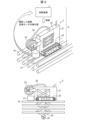
- a perspective view of the cleaning device 2 is shown on the upper side of FIG. 2, and a side view of the cleaning device 2 is shown on the lower side of FIG.
- the pipes PI are straight pipes and are arranged in multiple rows at equal intervals in the horizontal direction. In addition, the pipes PI are arranged in multiple stages in the vertical direction.
- the pipes PI are pipes of a boiler (not shown) used for power generation using waste heat from an incinerator, that is, boiler water pipes described above.
- the cleaning system 5 can be used for cleaning tubes other than the boiler water tubes as long as the cleaning system 5 is strong enough to allow the cleaning device 2 to run thereon and at least a portion of it is linear. can.
- the cleaning device 2 includes a body portion 21, a crawler 22, a hose reel 23, and a hose 24, and a pantograph 25 is housed inside the body portion 21. Further, as shown in the side view of FIG. 2, a water outlet 26 is provided at the tip of the pantograph 25. A housing portion 27 is provided at the front end portion of the body portion 21 .
- the crawler 22 functions as a traveling device that moves the cleaning device 2 forward, backward, and rotates in a horizontal plane.
- Other types of traveling devices such as wheels may be applied instead of the crawler 22 .
- a hose 24 is wound around the hose reel 23 , and the hose 24 is a pipe that feeds a liquid (for example, water) for cleaning the pipe PI to the water outlet 26 .
- the pantograph 25 is adapted to be extended and contracted by a link mechanism, so that the pantograph 25 can be extended downward from the main body 21 during cleaning and can be contracted during movement.
- the water discharge port 26 is connected to the hose 24 and discharges the cleaning liquid sent from the hose 24 sideways.
- the cleaning device 2 extends the pantograph 25 to position the water outlet 26 on the side of the pipe PI to be cleaned, and in this state, the cleaning liquid sent from the hose 24 is sent to the water outlet 26. Therefore, it is configured to wash the pipe PI with water pressure. Any method may be used to clean the pipe PI.
- the pipe PI may be cleaned by pressing a cleaning tool such as a brush against the pipe PI.
- the cleaning device 2 Since the cleaning device 2 performs cleaning by lowering the pantograph 25 between the pipes PI to be cleaned, it is necessary to move between the pipes PI to be cleaned as a pre-cleaning stage. In order to automatically perform this movement, a photographing device and a proximity sensor are provided inside the housing portion 27 of the cleaning device 2 (both of which are not shown in FIG. 2).
- control device 1 acquires the image captured by the imaging device and the detection value of the proximity sensor, and controls the cleaning device 2 based on these.
- the cleaning device 2 can be automatically moved between the pipes PI to be cleaned, and the cleaning device 2 can clean the pipes PI.
- FIG. 1 is a block diagram showing an example of the main configuration of the control device 1.
- the control device 1 includes a control section 10 that controls each section of the control device 1 and a storage section 11 that stores various data used by the control device 1 .
- the control device 1 also includes a communication unit 12 for communicating with other devices, an input unit 13 for receiving input of various data to the control device 1, and a device for outputting various data from the control device 1. and an output unit 14 .
- the control unit 10 includes a tube detection unit 101 , an angle identification unit 102 , a deviation amount calculation unit 103 and a movement control unit 104 .
- the pipe detection unit 101 detects the pipe PI from the image captured by the imaging device attached to the cleaning device 2 . Images may be obtained via the communication unit 12 or the input unit 13 .
- the angle identification unit 102 identifies the inclination angle of the pipe PI detected by the pipe detection unit 101 .
- the displacement calculation unit 103 calculates the amount of displacement of the cleaning device 2 from a predetermined reference position based on the detection values of a pair of proximity sensors that detect the pipe PI and are attached to the cleaning device 2 at symmetrical positions. calculate.
- the reference position is the center position of two pipes PI arranged adjacently in parallel (a position equidistant from the two pipes PI), and the deviation amount calculation unit 103 is the cleaning device 2 and the center position of the two pipes PI will be described.
- the reference position may be determined as appropriate, and is not limited to this example.
- the center position of one pipe PI may be used as a reference position, and the amount of deviation between the center position of the cleaning device 2 in the left-right direction and the center position of one pipe PI may be calculated.
- the movement control unit 104 performs movement control of the cleaning device 2 based on either or both of the tilt angle specified by the angle specifying unit 102 and the deviation amount calculated by the deviation amount calculation unit 103 . Although the details will be described later, the movement control unit 104 performs, for example, turning control for changing the direction of the cleaning device 2 and control for moving the cleaning device 2 to the central position of the adjacent pipes PI. Here, it is assumed that turning control in which the position of the control device 2 does not change is also included in the category of movement control.
- control device 1 includes the tube detection unit 101 that detects the pipe PI from the image captured by the imaging device attached to the cleaning device 2 that cleans the surface of the pipe PI, and the It includes an angle specifying unit 102 that specifies the inclination angle of the pipe PI, and a movement control unit 104 that controls the movement of the cleaning device 2 based on the specified inclination angle.
- the tilt angle of the pipe PI in the image captured by the imaging device attached to the cleaning device 2 reflects the orientation of the cleaning device 2 with respect to the pipe PI. If the orientation of the cleaning device 2 with respect to the pipe PI can be identified, the direction of the cleaning device 2 can be changed so that it is oriented in a predetermined orientation with respect to the pipe PI. It also becomes possible to move the cleaning device 2 along the pipe PI or to move the cleaning device 2 in a direction perpendicular to the pipe PI.
- movement control of the cleaning device 2 can be realized based on the image captured by the imaging device.
- the above configuration does not require a special configuration such as an arm for correcting the stop position, so it is more versatile than the technique of Patent Document 1. Therefore, according to the above configuration, there is an effect that general-purpose movement control of the cleaning device 2 can be realized.
- FIG. 3 is a diagram showing an outline of tube detection and inclination angle specification by the control device 1.
- FIG. 2 shows a top view of the cleaning device 2 positioned on the pipe PI and an image IMG taken by the imaging device 271 provided by the cleaning device 2 . Note that the appearance of the cleaning device 2 is simplified from that of FIG. This also applies to the drawings after FIG. 3 .
- a photographing device 271 is provided at the front portion of the cleaning device 2 .
- This photographing device 271 is housed in the housing portion 27 of FIG. 2 and arranged so as to photograph the lower side of the cleaning device 2 .
- the photographing device 271 may be any device capable of photographing an image in which the outline of the pipe PI can be recognized, and may be, for example, a depth camera.
- the pipe PI is shown tilted upward to the right as shown.
- the tube detection unit 101 detects a line segment L1 forming the outer edge of the tube PI from the image IMG.
- the angle specifying unit 102 specifies the inclination angle of the line segment L1 detected by the pipe detection unit 101 with respect to the line segment L2 as the inclination angle of the pipe PI.
- Line segment L2 is a line segment perpendicular to the upper and lower sides of image IMG.
- the tilt angle of the pipe can be expressed by making the tilt on the right side positive and the tilt on the left side negative. In this case, as shown in FIG. 3, ⁇ becomes a positive value when the front side of the cleaning device 2 is tilted to the left, and ⁇ becomes a negative value when the front side of the cleaning device 2 is tilted to the right.
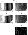
- FIG. 4 is a diagram showing a specific example of pipe detection by the control device 1.
- FIG. IMG 1 shown in FIG. 4 is an image captured by the imaging device 271 .
- this image IMG1 in regions A1 and A2, etc., the outer edge of the tube, which should be straight, is distorted and curved. Such distortion occurs when the lens of the photographing device 271 is a wide-angle lens.
- Proximity sensors are reflected in the lower left and lower right corners of image IMG1.
- tube detection unit 101 performs distortion correction on image IMG1 to generate distortion-corrected image IMG2.
- image IMG2 the outer edges of the tube are straightened in areas A1' and A2' corresponding to areas A1 and A2. Since the pattern of distortion that occurs depends on the photographing device 271, for example, a check pattern may be photographed in advance by the photographing device 271, and a correction parameter may be created so as to eliminate the distortion of the photographed check pattern. Distortion can be corrected by using such correction parameters.
- IMG3 shown in FIG. 4 is also an image captured by the imaging device 271, and interference fringes are generated in the area A3 and the like of this image IMG3. Such noise can also interfere with tube detection. Therefore, the tube detection unit 101 may perform noise removal prior to tube detection.
- An image IMG4 shown in FIG. 4 is obtained by performing noise removal processing on the image IMG3. The image IMG4 is a clear image without interference fringes.
- noise may be removed by a bilateral filter. Since the bilateral filter is a filter that removes noise and leaves sharp edge portions in an image, it is suitable as a noise removal filter used for preprocessing for tube detection.
- the tube detection unit 101 detects line segments that form the outer edge of the tube from the image that has been subjected to distortion correction and noise removal as described above.
- Various edge detection methods can be applied to detect this line segment.
- the tube detection unit 101 may perform edge detection using the Canny method. In the Canny method, after converting a target image into a grayscale, a portion of the converted image where the luminance change is equal to or greater than a threshold value is detected as an edge.
- FIG. 4 shows an edge image IMG5 representing the result of edge detection by the Canny method from the image IMG4.
- the edge image IMG5 is a binarized image in which various edges including the outer edge of the pipe are represented by white line segments, and portions other than the edges are black background portions.
- the tube detection unit 101 detects a straight line from the edge image IMG5. Since the detected straight line includes the edge of the outer edge of the pipe, the process of detecting the straight line can be said to be the process of detecting the pipe.
- the tube detection unit 101 may detect a straight line by Hough transform.
- each straight line of a predetermined length or more (each straight line made up of a predetermined number or more of white pixels) included in the edge image IMG5 is represented by polar coordinates ( ⁇ , ⁇ ).
- polar coordinates ( ⁇ , ⁇ )
- the straight line detection target area may be determined in advance.
- the angle identification unit 102 performs the above processing on all straight lines detected by the tube detection unit 101, and identifies the inclination of each detected straight line.
- the angle identification unit 102 excludes the identified angles that exceed the threshold. Then, the angle identification unit 102 identifies the average value of the remaining angles as the inclination angle of the pipe.
- the detection of the pipe and the identification of the inclination angle may be performed multiple times in time series, and the moving average of each identification result may be identified as the inclination angle of the pipe.
- photographing by the photographing device 271 detection of the tube from the photographed image, and identification of the inclination angle are performed at a predetermined cycle (for example, several Hz to several tens of Hz), and a moving average of the identification results of a plurality of cycles is calculated. , the inclination angle of the tube in the plurality of cycles.
- the movement control unit 104 performs turning control in consideration of this time lag.
- the movement control unit 104 may perform turning control using the inclination angle ⁇ S represented by the following formula as a threshold.
- td is the dead time from the transmission of the control signal to the operation of the cleaning device 2
- ⁇ is the angular velocity of the cleaning device 2 during turning
- V is the running speed of the cleaning device 2 (running at the rotational speed of the motor during turning)
- a is the travel acceleration of the cleaning device 2 (acceleration in travel at the rotation speed of the motor during turning).
- the coefficient (1/2) of ⁇ in the following formula is set on the assumption that the angular velocity linearly decreases during the period from turning to stopping of turning.
- the coefficient of ⁇ is not limited to 1/2 as long as it corresponds to the variation pattern of the angular velocity during the period until turning stop.
- ⁇ S t d * ⁇ +V/a* ⁇ /2
- the movement control unit 104 outputs right turn, left turn, and stop (turn end) control signals according to the following conditions.
- the sign of ⁇ in the following conditional expression and the sign of ⁇ S on the right side change depending on how the reference axis is set. ⁇ > ⁇ T ⁇ S : Turn right ⁇ T + ⁇ S : Turn left
- ⁇ T + ⁇ S : Stop (end turning)
- the movement control unit 104 calculates the angular velocity ⁇ of the cleaning device 2, then the movement control unit 104 multiplies the angular velocity ⁇ by a predetermined dead time td to obtain the angle that changes during the time lag, that is, the above ⁇ S Calculate the value of the first term on the right side of the formula. Further, the movement control unit 104 calculates the value of the second term on the right side of the calculation formula for ⁇ S from the traveling speed V and the acceleration a of the cleaning device 2, and obtains the value of ⁇ S from this.
- the movement control unit 104 determines whether the magnitude of the tilt angle ⁇ (
- the movement control unit 104 outputs a turning stop signal. This is because the required accuracy is satisfied if
- the movement control unit 104 rotates the cleaning device 2 if
- the conditions for determining the turning direction are as described above. That is, the movement control unit 104 outputs a control signal for turning right if ⁇ > ⁇ S , and a control signal for turning left if ⁇ ⁇ S . After that, the movement control unit 104 returns to the determination of whether
- FIG. 5 is a diagram showing an outline of a method of calculating the amount of deviation by the amount-of-deviation calculating unit 103. As shown in FIG. FIG. 5 shows a plan view of the cleaning device 2 located on the pipes PIL and PIR and a cross-sectional view taken along line AA' in the plan view. In the cross-sectional view, illustration of elements other than the proximity sensors 272L and 272R and the pipes PIL and PIR provided in the cleaning device 2 is omitted.
- proximity sensors 272L and 272R are provided in the front portion of the cleaning device 2 .
- the proximity sensor 272L is provided on the left side of the center line L3 that bisects the cleaning device 2 in the horizontal direction, and the proximity sensor 272R is provided on the right side of the center line L3. is.
- These sensors are housed in housing 27 (see FIG. 2).
- the center line L3 is parallel to the pipes PIL and PIR, but is shifted to the left by ⁇ y with respect to the intermediate line L4 indicating the central position of the pipes PIL and PIR.
- the shift amount calculator 103 calculates this shift amount ⁇ y based on the detection values of the proximity sensors 272L and 272R.
- the distance from the proximity sensor 272L to the pipe PIL is shorter than the distance from the proximity sensor 272R to the pipe PIR, as shown in the cross-sectional view of FIG. Therefore, the difference between the detection value of the proximity sensor 272L and the detection value of the proximity sensor 272R does not become zero. For example, if the proximity sensors 272L and 272R, which detect smaller values as the distance to the object decreases, the difference between the detected values will be a negative value.
- the straight line L5 indicating the central position of the proximity sensors 272L and 272R is shifted from the straight line L6 indicating the central position of the pipes PIL and PIR. It can be seen that it is shifted to the left. Also, since the magnitude of the difference between the detected values reflects the magnitude of the amount of deviation, ⁇ y can be calculated from the magnitude of the difference between the detected values.
- a pair of proximity sensors 272L and 272R are preferably positioned so that when one is directly above the tube, the other is at the detection limit of the adjacent tube. The reason for such arrangement will be described with reference to FIGS. 6 and 7.
- FIG. 1 A pair of proximity sensors 272L and 272R are preferably positioned so that when one is directly above the tube, the other is at the detection limit of the adjacent tube. The reason for such arrangement will be described with reference to FIGS. 6 and 7.
- FIG. 6 is a diagram explaining the positional relationship between the proximity sensor 272 and the pipe PI and the relationship between the detected value of the proximity sensor 272.
- FIG. The proximity sensor 272 is the same sensor as the proximity sensors 272L and 272R.
- FIG. 6 shows the relationship between the amount of deviation of the proximity sensor 272 from the initial position (unit: mm) and the measurement value of the proximity sensor 272 (detection value of the proximity sensor 272, unit: volt).
- the initial position is about 5 mm to the left of the position directly above the pipe PI.
- the proximity sensor 272 is moved rightward from the initial position, and when the proximity sensor 272 is positioned directly above the pipe PI, that is, when the proximity sensor 272 comes closest to the pipe PI,
- the detected value is about 1.2V. This value is the minimum output value of the proximity sensor 272 .
- the detection value of the proximity sensor 272 increases, and when the pipe PI is out of the detection range, the detection value (voltage value) is about 5.5. 0V.
- This value is the maximum value of the output value of the proximity sensor 272 and is the boundary of the detection range of the proximity sensor 272 . That is, if the detected value (voltage value) is smaller than 5.0V, it can be said that the proximity sensor 272 has detected the pipe PI, and if it is 5.0V, it can be said that the pipe PI has not been detected.
- the relationship between the position of the proximity sensor 272 and the detected value has a different pattern when the distance to the pipe PI is relatively short and when it is close to the detection range boundary. Of these cases, when the distance to the pipe PI is relatively short, the relationship between the position of the proximity sensor 272 and the detected value can be formulated as a function by approximation. This function is shown in FIG. 6 as an "approximate curve".
- the approximate curve shows the amount of deviation when the voltage value (approximately 5.0 V) is outside the detection range, and when the proximity sensor 272 is closest to the pipe PI (the proximity sensor 272 D represents the difference from the deviation amount when the position is positioned at ).
- the proximity sensor 272 moves to the right by a distance D from the state in which the proximity sensor 272 is located right above the pipe PI, the detection value of the proximity sensor 272 does not reach the maximum value, but it is close to the maximum value. value.
- D is regarded as the detection limit distance
- D is regarded as the detection limit distance
- the proximity sensor 272 exists in the section from the position directly above the pipe PI to the position separated by D in the right direction, the detected value of the proximity sensor 272 deviates.
- the relationship with the amount can be approximated by an approximate curve as shown in FIG.
- the detection value of the proximity sensor 272 can approximate a constant value (approximately 5.0 V).
- the experiment was conducted by changing the distance between the proximity sensor 272 and the pipe PI when the proximity sensor 272 was closest to the pipe PI. , the position of the detection limit did not change. From this experimental result, it is reasonable to approximate the proximity portion with an approximate curve as shown in FIG. The maximum value of the proximity sensor 272) is also appropriate.
- FIG. 7 is a diagram illustrating the relationship between the positional relationship between the proximity sensors 272L and 272R and the tubes PIL and PIR, and the relationship between the approximate expressions of the detection values of the proximity sensors 272L and 272R.
- the deviation amount is zero when the left proximity sensor 272L is positioned directly above the left side pipe PIL of the two adjacent pipes.
- an approximation representing the relationship between the amount of deviation x from the position when the proximity sensors 272L and 272R are horizontally moved to the right from that position and the detection values V 1 and V 2 of the proximity sensors 272L and 272R. shows the formula.
- V 1 a(x ⁇ p) 2 +q
- a, p, and q are constants determined from the distance between the proximity sensors 272, the diameter of the pipes PI, the pitch of the pipes PI, and the distance between the proximity sensors 272 and the pipes PI.
- the proximity sensors 272L and 272R are arranged. Specifically, the distance in the horizontal direction from the proximity sensor 272R to the position directly above the pipe PIR is set to D when the proximity sensor 272L is positioned directly above the pipe PIL. Also, when the proximity sensor 272R is positioned directly above the pipe PIR, the horizontal distance from the proximity sensor 272L to the position directly above the pipe PIL is set to be D as well. To achieve such a positional relationship, the distance d between the proximity sensors 272L and 272R should be set to (P ⁇ D). P is the distance between the tubes PIL and PIR.
- the detected value V 1 becomes the minimum value V 1MIN (approximately 1.2 V) when the proximity sensor 272L is positioned right above the pipe PIL.
- V2 since the proximity sensor 272R is at the detection limit position of the tube PIR, V2 becomes the maximum value V2MAX (approximately 5.0V).
- V1 since the proximity sensor 272L is at the detection limit position of the tube PIL, V1 becomes the maximum value V1MAX (approximately 5.0V).
- the proximity sensor 272L detects the pipe PIL in the section from the state where the proximity sensor 272L is positioned right above the pipe PIL to the state where the proximity sensor 272R is positioned right above the pipe PIR. and the proximity sensor 272R is detecting the pipe PIR.
- the difference between the detection values of the proximity sensors 272L and 272R in this section can be expressed as follows.
- V 1 ⁇ V 2 V 1MAX ⁇ a(x ⁇ p ⁇ D) 2 ⁇ q
- the difference between the detection values of the proximity sensors 272L and 272R when only one of the proximity sensors 272L and 272R detects the pipe and when both of them detect the pipe can be easily calculated. It can be expressed by an approximate expression. By using these approximation formulas, it is possible to derive a function for obtaining the amount of deviation from the difference between the detection values of the proximity sensors 272L and 272R.
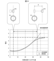
- FIG. 8 is a diagram showing a function for obtaining the amount of deviation from the difference (V 1 -V 2 ) between the detection values of the proximity sensors 272L and 272R.
- the vertical axis of the graph in FIG. 8 is the amount of deviation of the proximity sensor 272L from the position directly above the tube PIL (unit: mm), and the horizontal axis is the difference between the detection values of the proximity sensors 272L and 272R (voltage difference, unit: V). is.
- the function shown in FIG. 8 is a straight line (linear function) in the section from 0 to about 15 mm of the deviation amount. Specifically, the function in this section is a linear function in which the amount of deviation increases in proportion to the voltage difference (V 1 -V 2 ), as shown in Equation (1) in FIG.
- the function shown in FIG. 8 is a curve in the section where the amount of deviation is from 15 to around 45 mm.
- the function in this section is a function in which the amount of deviation decreases according to the value of (V 1 -V 2 ) 1/2 , as shown in Equation (2) in FIG.
- V 1MAX 5. That is, "5" in (V 1 -V 2 +q-5) of Equation (2) is V 1MAX .
- the deviation amount calculation unit 103 calculates the deviation amount Calculate x. Further, when only one of the proximity sensors 272L and 272R is detecting the pipe, the deviation amount calculation unit 103 calculates the deviation amount x by the above formula (2).
- the deviation amount calculation unit 103 calculates the deviation amount x by the above formula (2).
- the proximity sensor 272L when the proximity sensor 272L is positioned directly above the pipe PIL, the proximity sensor 272R is positioned at the detection limit of the pipe PIR, and when the proximity sensor 272R is positioned directly above the pipe PIR, the proximity
- the proximity sensors 272L and 272R By arranging the proximity sensors 272L and 272R so that the sensor 272L is at the detection limit of the pipe PIL, the amount of deviation can be calculated with the simple functions of equations (1) and (2).
- the shift amount calculation unit 103 sets the first term on the right side of Equation (2) to zero.
- the value of (V 1 ⁇ V 2 ) is positive or negative, in other words, the magnitude relationship between V 1 and V 2
- the center position of the adjacent pipes and the center position of the proximity sensors 272L and 272R may be in either the left or right direction. It is also possible to determine whether there is a deviation. Specifically, if V 1 >V 2 , it can be determined that there is a shift to the right, and if V 2 >V 1 , it can be determined that there is a shift to the left.
- control device 1 determines the amount of deviation of the cleaning device 2 from the predetermined reference position based on the detection values of the pair of proximity sensors 272L and 272R attached to the cleaning device 2 for detecting the pipe.
- a deviation amount calculation unit 103 is provided to calculate the amount of deviation.
- the movement control unit 104 performs movement control of the cleaning device 2 based on the tilt angle specified by the angle specifying unit 102 and the deviation amount calculated by the deviation amount calculation unit 103 .
- the pair of proximity sensors 272L and 272R are arranged so that when one is positioned directly above the pipe, the other is positioned at the detection limit of the pipe adjacent to the pipe. Then, the shift amount calculation unit 103 calculates the shift amount by using Equation (2), which is an approximation formula approximating the relationship between the difference between the detection values of the pair of proximity sensors 272L and 272R and the shift amount.
- proximity sensors 272L and 272R are attached to the cleaning device 2 at symmetrical positions to detect two pipes arranged in parallel, the cleaning device 2 is positioned at the center of the two pipes. At some point, the distance from proximity sensor 272L to tube PIL is equal to the distance from proximity sensor 272R to tube PIR. In this case, the output values of proximity sensors 272L and 272R are the same or substantially the same.
- the output values of the proximity sensors 272L and 272R are different values.
- the difference between the output values of the proximity sensors 272L and 272R corresponds to the amount of deviation between the center position of the cleaning device 2 in the horizontal direction and the center position between the pipes PIL and PIR.
- the deviation amount of the cleaning device 2 from the reference position can be calculated. For example, it is possible to calculate the amount of deviation between the central position of the cleaning device 2 in the left-right direction and the central position between the plurality of pipes arranged in parallel.
- the cleaning device 2 can be positioned at a predetermined position with respect to the pipe. For example, by controlling the movement of the cleaning device 2 so that the amount of deviation is zero, the cleaning device 2 can be positioned at the center position between the pipes.
- the output characteristics of the proximity sensor 272 are as follows: when the detection target is near the proximity sensor 272, and when the detection target is at a position away from the proximity sensor 272, i. different from case to case. Therefore, when approximating the output characteristics when the object to be detected is near the proximity sensor 272 by a quadratic expression, strictly speaking, the output characteristics when the object is near the detection limit must be approximated by another expression. be.
- the output characteristics of the proximity sensor 272 are divided into three types: the quadratic formula, the above another formula, and the constant.
- the formula for expressing the difference between the detection values becomes complicated, and the number of cases is increased, which complicates the calculation.
- the proximity sensors 272L and 272R of the cleaning device 2 are arranged so that when one is positioned directly above the pipe, the other is positioned at the detection limit of the pipe adjacent to the pipe. Then, the detected value at the position of the detection limit is approximated to be the maximum detected value.
- the above formula (1) is used, and when only one of the proximity sensors 272L and 272R is detecting the pipe, the above formula (2) is used.
- the amount of deviation can be calculated by a simple calculation.
- the proximity sensors 272L and 272R may be arranged in a predetermined direction and at a predetermined distance with respect to the reference position (for example, center position) of the cleaning device 2 .
- the reference position for example, center position
- one proximity sensor may be arranged a predetermined distance forward of the central position of the cleaning device 2 and the other proximity sensor may be arranged a predetermined distance rearward.
- the detector for detecting the pipe is not limited to the proximity sensor 272.
- any detector that can detect a pipe without contact such as a distance measurement sensor (for example, a laser distance measurement sensor) or an ultrasonic sensor, can be applied.
- the number of installed detectors is not limited to two, but may be three or more, and a plurality of types of detectors may be used together.
- the approximation formula that approximates the relationship between the difference in the detection value of the proximity sensor and the amount of deviation is not limited to the examples of formulas (1) and (2).
- it can be approximated by a higher-order function (including quadratic and cubic functions), an exponential function, a logarithmic function, or a combination thereof, depending on the type and arrangement of detectors for detecting tubes.
- the configuration using the formulas (1) and (2) described above is preferable because it has the advantage that the deviation amount can be calculated by a simple calculation.
- Centering control of the cleaning device 2 will be described here as an example of control of the cleaning device 2 based on the amount of deviation and the tilt angle described above. Centering refers to moving the cleaning device 2 to the center position between the pipes, and by centering, the pantograph 25 can be lowered between the pipes for cleaning (see FIG. 2). ).
- FIG. 9 is a diagram showing an operation example of the cleaning device 2 during centering. Note that FIG. 9 shows a view from above of the cleaning device 2 on the pipes PI1 to PI3 which are arranged parallel to each other at regular intervals. Further, in FIG. 9, the center position between the pipes PI1 and PI2 is indicated by a dashed line L7. When the dashed line L8 that bisects the cleaning device 2 in the horizontal direction coincides with the dashed line L7, the centering is completed.
- the movement control unit 104 first places the cleaning device 2 parallel to the pipes PI1 to PI3. Specifically, the movement control unit 104 acquires the latest tilt angle ⁇ specified by the angle specifying unit 102, sets the target tilt angle ⁇ T to zero, obtains the threshold ⁇ S , and
- It is determined whether ⁇ S (ST1). In the example of FIG. 9,
- ⁇ S (ST2).
- movement control section 104 acquires the latest displacement amount ⁇ y calculated by displacement amount calculation section 103, and determines whether
- y S (ST3).
- yS may be a value obtained by adding a predetermined margin to 0, for example. The margin is determined according to tube pitch, tube diameter, pandograph width, and the like. It is considered that the margin is often several millimeters. In the example of FIG. 9,
- the movement control unit 104 orients the cleaning device 2 in a direction that is inclined with respect to the extending direction of the pipes PI1 to PI3 and moves it forward or backward, thereby bringing ⁇ y closer to zero.
- the vehicle may move away from the start position of straight running by centering only forward or backward. For this reason, it is preferable to perform centering in a multi-step process of alternately repeating forward movement and backward movement.
- the movement control unit 104 determines the turning direction based on these determination results. Specifically, the movement control unit 104 determines to turn right when moving leftward and when the previous movement was forward movement. Further, the movement control unit 104 determines to turn left when moving leftward and when the previous movement was backward. The same is true when moving rightward, and the movement control unit 104 determines to turn left when the previous movement was forward, and to turn right when the previous movement was backward. do. In the example of FIG. 9, it is assumed that it is necessary to move to the right and that the previous movement was forward, so the movement control unit 104 determines to turn left ( ST4).
- the movement control unit 104 After determining the turning direction, the movement control unit 104 transmits to the cleaning device 2 an instruction to turn in the determined direction.
- the movement control unit 104 moves the cleaning device 2 forward or backward. Specifically, if the previous movement was forward movement, a backward movement instruction is transmitted to the cleaning device 2, and if the previous movement was backward movement, a forward movement instruction is transmitted to the cleaning device 2 (ST6). A method of determining the forward or backward travel time at this time, that is, the running time of the cleaning device 2 will be described later with reference to FIG. 10 .
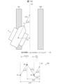
- FIG. 10 is a diagram illustrating a method of calculating the travel time of the cleaning device 2 during centering.
- FIG. 10 shows a state in which the cleaning device 2 is viewed from above. It should be noted that the cleaning device 2 is depicted in a smaller size.
- the center position of the pipes PIL and PIR parallel to each other is indicated by a dashed line L9, and the line bisecting the cleaning device 2 in the horizontal direction is indicated by a line L10.
- the angle between the dashed line L9 and the line L10 is ⁇ T
- the amount of deviation of the cleaning device 2 from the dashed line L9 is ⁇ y
- the moving distance from the center position of the cleaning device 2 to the position on the dashed line L9 when moving forward along the line L10 is LP .
- the movement control unit 104 may calculate the running time of the cleaning device 2 using Equation (3) shown in FIG. 10 .
- V in Expression (3) is the running speed of the cleaning device 2 .
- ⁇ y/sin( ⁇ T ) L P in Equation (3). That is, the formula (3 ) is obtained by multiplying L P by (1+k b ) instead of L P as the travel distance of the cleaning device 2 . This formula is used to find the running time. Since it is generally slippery on the pipe, it is possible to run a distance closer to the LP by calculating the running time after increasing the running distance in this way.
- kb ( kp + kn )/2, that is, the arithmetic mean value of the bias value kp at the time of the previous movement and the bias value kn at the time of the current movement may be kb .
- the current bias value kn is the ratio ( ⁇ y n / ⁇ y p ) between the positional deviation amount ⁇ y n after the most recent movement and the positional deviation amount ⁇ yp before the movement.
- EX1 in FIG. 10 shows an example in which centering is performed by moving in three steps from a state where the amount of positional deviation is ⁇ y1.
- a point P1 indicates the center position of the cleaning device 2 when the positional deviation amount is ⁇ y1.
- the positional deviation amount after the first stage movement is ⁇ y2
- the center position of the cleaning device 2 at this time is indicated by a point P2
- the positional deviation amount after the second stage movement is ⁇ y3
- the cleaning device 2 at this time is ⁇ y3.
- the center position is indicated by point P3.
- the movement control unit 104 calculates the running time by Equation (3) using the default bias value kd .
- ⁇ y1 may be substituted for ⁇ y in Equation (3).
- kd for example, the last used bias value kb may be applied, or a predetermined value may be applied.
- a predetermined constant smaller than .DELTA.y1 may be substituted for .DELTA.y in order to ensure that centering is always performed in a plurality of stages.
- This constant indicates the upper limit of the shift width in one stage of movement, and may be set in advance according to the space on the pipe. This constant is used to calculate the running time until the amount of deviation calculated by the deviation amount calculation unit 103 becomes equal to or less than this constant.
- the movement control unit 104 sets the ratio ( ⁇ y2/ ⁇ y1) of the amount of positional deviation ⁇ y2 after the movement of the first stage to the amount of positional deviation ⁇ y1 before the movement as the current bias value kn . calculate. Then, the movement control unit 104 sets the arithmetic average value of the calculated kn and the previously applied bias value kd as the bias value for the second stage movement. As a result, in the movement of the second stage, control of the movement distance is realized according to the deviation amount before and after the movement of the first stage.
- the movement control unit 104 sets the ratio ( ⁇ y3/ ⁇ y2) of the amount of positional deviation ⁇ y3 after the movement of the second stage to the amount of positional deviation ⁇ y2 before the movement as the current bias value kn . calculate. Then, the movement control unit 104 sets the arithmetic average value of the calculated kn and the previously applied bias value kb as the bias value for movement of the third stage. As a result, in the movement of the third stage, control of the movement distance is realized according to the deviation amount before and after the movement of the second stage.
- the movement in three stages reaches the position on the broken line L9, that is, the center position between the tubes PIL and PIR. Perform the fourth stage of movement.
- the movement control unit 104 may move the predetermined distance in multiple steps.
- the movement control unit 104 preferably adjusts the movement distance in the movement in the later stage according to the amount of deviation before and after the movement in the earlier stage.
- the movement distance may vary due to the slipperiness of the pipe surface. be. Therefore, according to the above configuration, when moving the cleaning device 2 by a predetermined distance, the predetermined distance is moved in a plurality of steps, and according to the deviation amount before and after the movement in the previous step, Adjust travel distance. This makes it possible to stably move the cleaning device 2 by a predetermined distance regardless of the surface condition of the pipe on which the cleaning device 2 moves.
- the adjustment is performed according to the amount of deviation before and after the movement immediately before, but the adjustment may be performed in consideration of the amount of deviation before that as well.
- the bias value bb may be used as Also, a weighted average value or the like may be used instead of the arithmetic average value.
- the movement control unit 104 After performing centering and cleaning at the central position of the pipe, the movement control unit 104 causes the cleaning device 2 to travel straight while maintaining the central position of the pipe. This allows different locations of the same tube to be cleaned.
- the tilt angle specified by the angle specifying unit 102 can be used to control the cleaning device 2 to travel straight while maintaining the central position between the pipes. This is because if the state of zero inclination angle can be maintained, the state of maintaining the central position between the pipes can also be maintained.
- the movement control unit 104 determines whether or not the amount of deviation calculated by the amount of deviation calculating unit 103 is equal to or less than a threshold value before traveling straight ahead. and may be controlled differently. For example, the movement control unit 104 may apply a high-speed straight mode in which the cleaning device 2 is moved at high speed in the former case, and may apply a low-speed straight mode in which the moving speed is slower than the high-speed straight mode in the latter case. good.
- the movement control unit 104 may calculate L/V, which is obtained by dividing the distance L to be moved by the running speed V, as the running time. be. After the cleaning device 2 starts traveling, the movement control unit 104 determines whether the tilt angle specified by the angle specifying unit 102 exceeds the allowable value. When the movement control unit 104 determines that the allowable value is exceeded, the movement control unit 104 adjusts the traveling direction of the cleaning device 2 .
- the cleaning device 2 when the cleaning device 2 is provided with crawlers 22 as shown in FIG.
- the direction of travel of the cleaning device 2 can be adjusted.
- the movement control unit 104 sets the travel time to L/V and checks the inclination angle until the travel of the distance L is completed, as in the high-speed straight travel mode. Control may be performed to increase the speed of one crawler 22 by ⁇ times when the value exceeds the value. However, when the low-speed straight mode is applied, it is preferable that the movement control unit 104 also confirms the amount of deviation, and adjusts the direction of movement of the cleaning device 2 when the amount of deviation exceeds the allowable value.
- the movement control unit 104 performs the above control when the tilt angle specified by the angle specifying unit 102 exceeds the allowable value, and when the tilt angle specified by the angle specifying unit 102 is below the allowable value Also, the deviation amount calculated by the deviation amount calculation unit 103 may be checked. Then, the movement control unit 104 may perform an operation to shift to the central position when the amount of deviation exceeds the allowable value. Note that the movement control unit 104 may return to the tilt angle confirmation process when the amount of deviation is equal to or less than the allowable value.
- the movement control unit 104 increases the speed of the left crawler 22 by ⁇ times ( ⁇ > ⁇ ). After running the cleaning apparatus 2 for a predetermined time with the speed of the left crawler 22 multiplied by ⁇ , the movement control unit 104 also multiplies the speed of the right crawler 22 by ⁇ to return the vehicle body angle. good. Further, when the deviation amount is a value indicating that the cleaning device 2 is shifted to the right side of the central position, the movement control unit 104 increases the speed of the right crawler 22 by ⁇ times. good.
- the movement control unit 104 After running the cleaning device 2 for a predetermined time with the speed of the right crawler 22 multiplied by ⁇ , the movement control unit 104 also multiplies the speed of the left crawler 22 by ⁇ to return the vehicle body angle. good.
- the control is reversed to the above. That is, the movement control unit 104 causes the sweeping device 2 to travel for a predetermined time with the speed of the left crawler 22 multiplied by ⁇ if it is on the left side, and sweeps with the speed of the right crawler 22 multiplied by ⁇ if it is on the right side.
- the device 2 is run for a predetermined time.
- the movement control unit 104 restores the speeds of the left and right crawlers 22 to the same speed, and starts the inclination angle confirmation process. Go back.
- the movement control unit 104 After cleaning the entire two adjacent pipes, the movement control unit 104 causes the cleaning device 2 to perform row movement. Note that a row in row movement refers to the portion between a tube and its adjacent tube.
- the movement control unit 104 first turns the cleaning device 2 to the target angle ⁇ T based on the tilt angle specified by the angle specifying unit 102, and moves it forward after completing the rotation.
- the travel time in this forward travel may be calculated, for example, by the following formula (4). note that. P is the distance between adjacent pipes and V is the traveling speed of the cleaning device 2 .
- the movement control unit 104 resets the tilt angle of the cleaning device 2 to zero based on the tilt angle specified by the angle specifying unit 102 .
- the cleaning device 2 is positioned at the center of the row before the row movement, and that the cleaning device 2 is advanced by P*sin( ⁇ T ) due to the above travel control.
- the amount of deviation of the cleaning device 2 from the center position of the row after movement at the time when the tilt angle is returned to zero is P* ⁇ cos( ⁇ T ) ⁇ 2 .
- the movement control unit 104 turns the cleaning device 2 by (90 ⁇ T ) based on the tilt angle specified by the angle specifying unit 102 . In this manner, the movement control unit 104 may turn the cleaning device 2 so that the first and second turning angles are different from each other by 90 degrees. Then, the movement control unit 104 causes the cleaning device 2 to move backward after the completion of the turning.
- the cleaning device 2 was positioned in the center of the row before the row movement, and that the cleaning device 2 was advanced by P*sin( ⁇ T ) due to the first forward travel.
- the cleaning device 2 is moved backward by P*cos( ⁇ T )
- the position of the cleaning device 2 after the backward movement will be a position that is P horizontally moved from the position of the cleaning device 2 before the row movement. Therefore, the running time in backward running is calculated by the following formula (5).
- Row movement is realized by a combination of turning, forward movement, turning, and backward movement as described above.
- the cleaning device 2 may be moved backward after the first turn, and in this case, the cleaning device 2 may be moved forward after the second turn.
- the turning direction may be determined according to which row the cleaning device 2 is to be moved to and the traveling direction of the cleaning device 2 . For example, to move to the left row, and to move the cleaning device 2 forward after the first turn, turn left.
- the shift amount calculation unit 103 may calculate the shift amount ⁇ y from the center position of the row after movement after the first run. Then, the movement control unit 104 may adjust the second running time according to the deviation amount ⁇ y calculated by the deviation amount calculation unit 103 . In other words, the movement control unit 104 may calculate the second running time using the shift amount ⁇ y calculated after the end of the first running.
- the shift amount calculation unit 103 calculates the shift amount ⁇ y from the center position of the column after movement. Here, if the amount of deviation ⁇ y exceeds the allowable range, the centering described above is performed.
- the movement control unit 104 acquires the tilt angle specified by the angle specifying unit 102 prior to various controls as described above, and determines whether or not the tilt angle is within a preset invalid range. You can judge. Then, if the tilt angle acquired in time series from the angle specifying unit 102 is within the invalid range for a predetermined number of times, the movement control unit 104 transmits an abnormal signal and ends the control of the cleaning device 2. good too. This can prevent unintended control from being performed.
- the control device 1 can cause operations such as centering, row movement, and straight ahead. Which of these operations should be performed may be determined by the control device 1, or may be determined by another control device provided upstream of the control device 1.
- FIG. the control device on the upstream side determines the operation to be performed by the cleaning device 2, for example, according to the operator's operation, and notifies the control device 1 of the determined operation.
- the control device 1 operates the cleaning device 2 according to this notification, and notifies the upstream control device of the completion notification when the operation is completed. After receiving the completion notification, the control device on the upstream side determines the operation to be performed next, and notifies the control device 1 of the determined operation.
- control of expansion and contraction of the pantograph 25, control of water discharge, and the like, which do not use the amount of deviation or the angle of inclination, may be performed by the control device 1 or may be performed by a control device on the upstream side. .
- FIG. 11 is a flow chart showing an example of a control method for the cleaning device 2 based on the tilt angle.
- the cleaning device 2 is arranged on a plurality of water pipes arranged in parallel, and the water pipes are photographed by the imaging device 271 attached to the cleaning device 2.
- the tube detection unit 101 acquires an image captured by the imaging device 271 attached to the cleaning device 2 . Then, in S12, the tube detection unit 101 detects water tubes from the image acquired in S11. Since the water tube detection method has already been explained, the explanation will not be repeated here.
- the angle specifying unit 102 specifies the inclination angle of the pipe detected in S12. Since the method of identifying the tilt angle of the tube detected in the image has already been described, the description will not be repeated here.
- the movement control unit 104 determines whether or not to control the cleaning device 2 based on the tilt angle specified at S13. If it is determined not to perform control here (NO in S14), the process of FIG. 11 ends. On the other hand, if it is determined that control should be performed (YES in S14), the process proceeds to S15, and the movement control unit 104 controls the cleaning device 2 based on the tilt angle specified in S13. 11 processing ends.
- control content of S15 Various things can be applied as the control content of S15, and the criterion of S14 may be appropriately set according to the control content of S15.
- the movement control unit 104 performs turning control for setting the tilt angle of the cleaning device 2 to ⁇ T in S15, in S14, if the tilt angle specified in S13 is within the allowable range from ⁇ T , Control is not required, and if ⁇ T is not within the allowable range, it is determined that control is required.
- the movement control unit 104 when the movement control unit 104 causes the cleaning device 2 to travel straight, in S14, if the tilt angle specified in S13 is within the allowable value, no control is required; It is determined that control is required. Then, in S15, the movement control unit 104 adjusts the speed of the crawler 22 so that the tilt angle specified in S13 becomes zero or approaches zero.
- the control method for the cleaning device 2 executed by the control device 1 includes the tube detection step (S12 ), an angle identification step (S13) for identifying the pipe inclination angle detected in the pipe detection step, and a movement control step (S15) for controlling the movement of the cleaning device 2 based on this inclination angle.
- this control method general-purpose movement control of the cleaning device 2 based on the image photographed by the photographing device 271 can be realized.
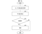
- FIG. 12 is a flow chart showing an example of a control method for the cleaning device 2 based on the deviation amount.
- the cleaning device 2 is positioned between a pair of adjacent water pipes among a plurality of water pipes arranged in parallel.
- the deviation amount calculation unit 103 acquires detection values of a pair of proximity sensors 272L and 272R attached to the cleaning device 2 at symmetrical positions. Then, in S22, the displacement amount calculator 103 calculates the amount of displacement of the cleaning device 2 from the predetermined reference position based on the detection value acquired in S21. For example, the deviation amount calculator 103 calculates the amount of deviation between the central position of the cleaning device 2 in the horizontal direction and the central position between the plurality of pipes arranged in parallel.
- deviation amount calculation section 103 substitutes the difference between the detection values into the above-described formula (1) to calculate the deviation amount.
- the deviation amount calculation unit 103 calculates Substitute the difference to calculate the amount of deviation.
- the movement control unit 104 determines whether or not to control the cleaning device 2 based on the amount of deviation calculated at S22. If it is determined not to perform control here (NO in S23), the process of FIG. 12 ends. On the other hand, if it is determined that control should be performed (YES in S23), the process proceeds to S24, and the movement control unit 104 controls the cleaning device 2 based on the deviation amount calculated in S22. 12 processing ends.
- control contents of S24 may be appropriately set according to the control contents of S24.
- the movement control unit 104 determines that control is not required if the amount of deviation calculated in S22 is within the allowable value, and that control is required if it exceeds the allowable value. Then, in S24, the movement control unit 104 performs control to reduce the deviation amount. For example, the movement control unit 104 performs control to move the cleaning device 2 forward or backward after turning it to a predetermined inclination angle, or control to increase or decrease the speed of one of the left and right crawlers 22 .
- the control method of the cleaning device 2 executed by the control device 1 is based on a set of pipe detection devices mounted at symmetrical positions of the cleaning device 2 for cleaning a plurality of pipes arranged in parallel.
- a pair of proximity sensors 272L and 272R are positioned so that when one is directly above the tube, the other is at the detection limit of the tube adjacent to that tube.
- the deviation amount calculation step the difference between the detection values of the pair of proximity sensors 272L and 272R and the approximate expression (2) that approximates the relationship between the deviation amount, or the detection value of the proximity sensors 272L and 272R.
- the amount of deviation is calculated using Equation (1), which is an approximation formula in which the relationship between the difference and the amount of deviation is approximated by a linear function.
- Equation (1) is an approximation formula in which the relationship between the difference and the amount of deviation is approximated by a linear function.
- the deviation amount can be calculated by simple calculation using a simple approximation formula.
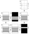
- FIG. 13 is a diagram showing an example of calculation of the amount of deviation based on the detection result of the tube detection unit 101. As shown in FIG.
- the configuration of the control device according to the present embodiment is the same as the configuration of the control device 1 according to the first embodiment (see FIG. 1), except that the content of the processing executed by the shift amount calculation unit 103 is changed.
- the control device of the form is also called the control device 1 .
- the cleaning device of this embodiment is similar to the cleaning device 2 of Embodiment 1, the cleaning device of this embodiment will also be referred to as the cleaning device 2 .
- the cleaning device 2 of this embodiment differs from the cleaning device 2 of Embodiment 1 in that the proximity sensor 272 does not need to be provided.
- the pipe detection unit 101 detects pipes from images captured by the imaging device 271 attached to the cleaning device 2 .
- four contour lines of the tube are detected from the image IMG6 captured by the imaging device 271 .
- the image IMG6 shows the pipes PI11 to PI14, of which the pipes PI11 and PI14 are located on the contact surface (uppermost) with the cleaning device 2, and the pipes PI12 and PI13 are on the far side ( second stage).
- the right edge contour of the pipe PI11 and its upper endpoint p1 the right edge contour of the pipe PI12 and its upper endpoint p2, the left edge contour of the pipe PI13 and its upper endpoint p3, the left edge contour of the pipe PI14 and its upper endpoint p3.
- a top end point p4 has been detected.
- the deviation amount calculation unit 103 may specify the inter-tube region from the image IMG6 when calculating the deviation amount.
- the shift amount calculation unit 103 uses the tilt angle identified by the angle identification unit 102 and the coordinate values of the upper endpoints p1 to p4 to determine the lower endpoints corresponding to the upper endpoints p1 to p4. Identify and identify a rectangular area defined by the upper and lower endpoints. Then, the shift amount calculation unit 103 determines whether or not the specified rectangular area is the inter-tube area.
- the deviation amount calculation unit 103 specifies the lower end point p6 corresponding to the upper end point p4, and then specifies the lower end point p5 corresponding to the upper end point p3 adjacent to the upper end point p4.
- a rectangular area defined by four points p3, p4, p6, and p5 is specified.
- the deviation amount calculation unit 103 masks the outside of the specified rectangular area with black, and then converts it to gray scale. Then, the shift amount calculation unit 103 calculates a histogram of pixel values in the rectangular area, and determines that it is an inter-tube area if the median value is smaller than a threshold value (for example, 100). Normally, the area in which the uppermost tubes PI11 and PI14 are photographed has a higher pixel value than the inter-pipe area. Therefore, by the above determination, the area in which the uppermost tubes PI11 and PI14 are photographed is distinguished from the inter-tube area. be able to. In this example, a rectangular area defined by four points p3, p4, p6, and p5 is determined as an inter-tube area.
- the deviation amount calculation unit 103 identifies the lower end point p7 corresponding to the upper end point p1.
- the shift amount calculation unit 103 specifies the lower end point p8 corresponding to the upper end point p3 next to the upper end point p2 without specifying the lower end point corresponding to the upper end point p2. , thereby specifying a rectangular area defined by four points p1, p3, p8, and p7.
- the shift amount calculation unit 103 does not specify the bottom end point for the adjacent top end point, and You may make it specify a point. This is because it is unlikely that any two endpoints in close proximity will be tube ends.
- the shift amount calculation unit 103 After identifying the rectangular area defined by the four points p1, p3, p8, and p7, the shift amount calculation unit 103 masks the outside of the identified rectangular area with black and converts it to gray scale, similarly to IMG8. (IMG10). Then, the shift amount calculation unit 103 calculates a histogram of pixel values in the rectangular area, and determines that the area is an inter-tube area if the median value is smaller than the threshold value. In this example, a rectangular area defined by four points p1, p3, p8, and p7 is determined as an inter-tube area. Such processing is performed for all rectangular areas formed based on the detected upper end points.
- the deviation amount calculation unit 103 calculates the specified tube-to-tube area. integrate. Specifically, of the coordinates of the vertices of the specified inter-tubular region, the deviation amount calculation unit 103 calculates the coordinates located on the upper leftmost, the coordinates located on the lower left, and the coordinates located on the lower right. , and the coordinates located on the upper right side. Then, the deviation calculation unit 103 takes the area defined by those coordinates as the final inter-pipe area.
- the deviation amount calculation unit 103 calculates Among the vertices, four p1, p7, p6 and p4 are specified as shown in IMG11. As a result, the final inter-tube area is identified as a rectangular area defined by four points p1, p7, p6, and p4.
- the deviation amount calculation unit 103 obtains the midpoints of the points p1 and p4 and the midpoints of the points p7 and p6, and calculates the line segment L11 connecting the midpoints. and a line segment L12 that bisects the image IMG12 in the horizontal direction.
- control device 1 may include the displacement amount calculation unit 103 that calculates the amount of displacement of the cleaning device 2 from the reference position based on the detection result of the pipe detection unit 101 .
- the movement control unit 104 may be configured to perform movement control of the cleaning device 2 based on the tilt angle specified by the angle specifying unit 102 and the deviation amount calculated by the deviation amount calculation unit 103 .
- the position of the pipe in the image captured by the imaging device 271 attached to the cleaning device 2 reflects the positional relationship between the cleaning device 2 and the pipe. Therefore, the deviation amount of the cleaning device 2 can be calculated by detecting the pipe from this image. By performing movement control using this deviation amount, the cleaning device 2 can be positioned at a predetermined position with respect to the pipe.
- the execution subject of each process described in each of the above embodiments is arbitrary, and is not limited to the above examples.
- the device configuration is arbitrary.
- the processing of specifying the tilt angle, the processing of calculating the amount of deviation, and the processing of controlling the operation of the cleaning device 2 are performed by separate information processing devices. You may let Further, for example, the first control device 1 performs a process of specifying the tilt angle and a process of controlling the operation of the cleaning device 2 based on the specified tilt angle, and the second control device 1 determines the amount of deviation.
- a configuration may be adopted in which the calculation process and the operation control process of the cleaning device 2 are performed based on the calculated deviation amount.
- control device 1 may be mounted on the cleaning device 2 .
- the cleaning device 2 provided with the control device 1 and moving according to the control of the control device 1 is also included in the scope of the present invention.
- the cleaning device 2 equipped with the control device 1 can move alone to a predetermined position on the pipe.
- control device 1 The function of the control device 1 (hereinafter referred to as “device”) is a program for causing a computer to function as the device, and the computer functions as each control block (especially each part included in the control unit 10) of the device. It can be realized by a program (control program) for causing the
- the device comprises a computer having at least one control device (eg processor) and at least one storage device (eg memory) as hardware for executing the program.
- control device eg processor
- storage device eg memory
- the above program may be recorded on one or more computer-readable recording media, not temporary.
- the recording medium may or may not be included in the device.
- the program may be supplied to the device via any transmission medium, wired or wireless.
- control blocks can be realized by logic circuits.
- integrated circuits in which logic circuits functioning as the control blocks described above are formed are also included in the scope of the present invention.
- control blocks described above it is also possible to implement the functions of the control blocks described above by, for example, a quantum computer.
- control device 101 tube detection unit 102 angle identification unit 103 deviation amount calculation unit 104 movement control unit 2 cleaning device 271 imaging device 272 (272R, 272L) proximity sensor
Landscapes
- Engineering & Computer Science (AREA)
- Mechanical Engineering (AREA)
- Aviation & Aerospace Engineering (AREA)
- Radar, Positioning & Navigation (AREA)
- Remote Sensing (AREA)
- Physics & Mathematics (AREA)
- General Physics & Mathematics (AREA)
- Automation & Control Theory (AREA)
- Cleaning In General (AREA)
- Control Of Position, Course, Altitude, Or Attitude Of Moving Bodies (AREA)
Abstract
管の清掃装置の汎用的な移動制御を実現する。制御装置(1)は、管の表面を清掃する清掃装置(2)に取り付けられた撮影装置(271)により撮影された画像から管を検出する管検出部(101)と、管検出部(101)が検出した管の傾斜角度を特定する角度特定部(102)と、傾斜角度に基づいて清掃装置2の移動制御を行う移動制御部(104)と、を備える。
Description
本発明は、配管の清掃を行う清掃装置の移動制御を行う制御装置に関する。
焼却炉の廃熱を利用した発電に用いられるボイラは多数の配管を備えている。それらの配管は、焼却炉で発生する排ガスの排出路に配置され、その内部には水や水蒸気等の流体が流される。このため、上記配管はボイラ水管とも呼ばれる。そして、排ガスとボイラ水管を流れる流体との間の熱交換により、焼却により発生した熱エネルギを回収する。
このように、ボイラ水管は排ガスに晒されるため、ボイラ水管の表面には焼却炉で発生した飛灰などが付着して堆積し、熱交換効率が低下していく。よって、ボイラ水管の表面を定期的に清掃する必要がある。しかしながら、ボイラ水管の人手による清掃は容易ではなく、清掃装置による自動清掃が従来から検討されている。
例えば、下記の特許文献1には、清掃治具を搭載してボイラ水管群の管軸方向に移動する水管群走行清掃装置を備えた清掃装置が開示されている。この水管群走行清掃装置は、清掃すべきボイラ水管とボイラ水管の間に降ろされた状態で、ボイラ水管の側面に沿って移動しながら清掃を行う。水管群走行清掃装置は、管列方向への移動はできないため、ボイラ水管群の管列方向に移動する管列方向移動装置に収容された状態で移動された後、次に清掃するボイラ水管の間に降ろされる。
特許文献1の清掃装置は、水管群走行清掃装置がボイラ水管の間に降ろされた状態で、ボイラ水管に沿って移動することしかできない。このため、清掃の開始時には、まず、水管群走行清掃装置をボイラ水管の間に降ろすことのできる位置に停止させる必要がある。
しかしながら、水管群走行清掃装置を常に正しい位置に停止させることは難しい。このため、特許文献1の清掃装置は、水管群走行清掃装置の停止位置を修正するための停止位置修正用アームを備えている。
このように、特許文献1の清掃装置は、清掃装置を自動で移動させるために、停止位置修正用アームのような特殊な機構を必要とするという点で汎用性に欠ける。本発明の一態様は、管の清掃を行う清掃装置の汎用的な移動制御を実現することを目的としている。
上記の課題を解決するために、本発明の一態様に係る制御装置は、管の表面を清掃する清掃装置に取り付けられた撮影装置により撮影された画像から前記管を検出する管検出部と、前記管検出部が検出した前記管の傾斜角度を特定する角度特定部と、前記傾斜角度に基づいて前記清掃装置の移動制御を行う移動制御部と、を備える。
上記の課題を解決するために、本発明の一態様に係る制御装置は、平行に配列された複数の管を清掃する清掃装置の左右対称な位置に取り付けられた、前記管を検出する一組の近接センサの検出値に基づいて、前記清掃装置の所定の基準位置からのずれ量を算出するずれ量算出部と、前記ずれ量に基づいて前記清掃装置の移動制御を行う移動制御部と、を備え、一組の前記近接センサは、一方の近接センサが前記管の真上の位置となるときに、他方の近接センサが当該管に隣接する管の検出限界の位置となるように配置されており、前記ずれ量算出部は、一組の前記近接センサの検出値の差と、前記ずれ量との関係を近似した近似式を用いて前記ずれ量を算出する。
上記の課題を解決するために、本発明の一態様に係る清掃装置の制御方法は、制御装置が実行する清掃装置の制御方法であって、管の表面を清掃する前記清掃装置に取り付けられた撮影装置により撮影された画像から前記管を検出する管検出ステップと、前記管検出ステップで検出した前記管の傾斜角度を特定する角度特定ステップと、前記傾斜角度に基づいて前記清掃装置の移動制御を行う移動制御ステップと、を含む。
上記の課題を解決するために、本発明の一態様に係る清掃装置の制御方法は、制御装置が実行する清掃装置の制御方法であって、平行に配列された複数の管を清掃する前記清掃装置の左右対称な位置に取り付けられた、前記管を検出する一組の近接センサの検出値に基づいて、前記清掃装置の所定の基準位置からのずれ量を算出するずれ量算出ステップと、前記ずれ量に基づいて前記清掃装置の移動制御を行う移動制御ステップと、を含み、一組の前記近接センサは、一方の近接センサが前記管の真上の位置となるときに、他方の近接センサが当該管に隣接する管の検出限界の位置となるように配置されており、前記ずれ量算出ステップでは、一組の前記近接センサの検出値の差と、前記ずれ量との関係を近似した近似式を用いて前記ずれ量を算出する。
本発明の一態様によれば、管の清掃装置の汎用的な移動制御を実現することができる。
〔実施形態1〕
(清掃システムの概要)
本実施形態に係る清掃システム5の概要を図2に基づいて説明する。図2は、清掃システム5の概要を示す図である。清掃システム5は、管PIの表面を清掃するためのシステムであり、制御装置1と清掃装置2を含む。制御装置1は、清掃装置2の動作を制御する装置である。清掃装置2は、制御装置1の制御に従って動作する、管PIの清掃装置である。図2の上側には清掃装置2の斜視図を示し、同図の下側には清掃装置2の側面図を示している。
(清掃システムの概要)
本実施形態に係る清掃システム5の概要を図2に基づいて説明する。図2は、清掃システム5の概要を示す図である。清掃システム5は、管PIの表面を清掃するためのシステムであり、制御装置1と清掃装置2を含む。制御装置1は、清掃装置2の動作を制御する装置である。清掃装置2は、制御装置1の制御に従って動作する、管PIの清掃装置である。図2の上側には清掃装置2の斜視図を示し、同図の下側には清掃装置2の側面図を示している。
管PIは、直線状の管であり、水平方向に等間隔で複数列配列している。また、管PIは垂直方向に複数段配列している。本実施形態では、管PIが、焼却炉の廃熱を利用した発電に用いられるボイラ(図示せず)の配管、すなわち上述のボイラ水管である例を説明する。無論、清掃システム5は、清掃装置2がその上を走行することができる程度の強度を有し、少なくとも一部分が直線状であるものであれば、ボイラ水管以外の管の清掃にも用いることができる。
図示のように清掃装置2は、本体部21、クローラ22、ホースリール23、およびホース24を備え、本体部21の内部にはパンタグラフ25が収容されている。また、図2の側面図に示すように、パンタグラフ25の先端部には放水口26が設けられている。また、本体部21の前方側端部には収容部27が設けられている。
図2には、左側のクローラ22のみを示しているが、クローラ22は本体部21を挟んで左右対称な位置に一組設けられている。クローラ22は、清掃装置2を前進、後進、および水平面内で回転させる走行装置として機能する。クローラ22の代わりに車輪などの他種の走行装置を適用してもよい。
ホースリール23はホース24を巻きつけるものであり、ホース24は放水口26に管PIの洗浄用の液体(例えば水)を送液する管である。パンタグラフ25は、リンク機構により伸縮するようになっており、清掃時には本体部21の下方に向かってパンタグラフ25を伸ばし、移動時にはパンタグラフ25を収縮させることができる。また、放水口26は、ホース24に接続されており、ホース24から送られてきた洗浄用の液体を側方に向かって放出する。
つまり、清掃装置2は、パンタグラフ25を伸長させて、放水口26を清掃したい管PIの側方に位置させ、この状態でホース24から送られてきた洗浄用の液体を放水口26に送り込むことにより、水圧で管PIを洗浄する構成となっている。なお、管PIを清掃する方式は任意であり、例えばブラシなどの清掃具を管PIに押し当てて清掃する構成としてもよい。
清掃装置2は、清掃したい管PIの間にパンタグラフ25を降ろして清掃を行うため、清掃の前段階として、清掃したい管PIの間に移動する必要がある。この移動を自動で行うために、清掃装置2の収容部27の内部には撮影装置と近接センサが設けられている(何れも図2には図示せず)。
そして、制御装置1は、撮影装置が撮影した画像と近接センサの検出値を取得し、これらに基づいて清掃装置2の制御を行う。これにより、清掃装置2を清掃すべき管PIの間に自動で移動させて、清掃装置2に管PIの清掃を行わせることができるようになっている。
(制御装置の構成)
制御装置1の構成を図1に基づいて説明する。図1は、制御装置1の要部構成の一例を示すブロック図である。図示のように、制御装置1は、制御装置1の各部を統括して制御する制御部10と、制御装置1が使用する各種データを記憶する記憶部11を備えている。また、制御装置1は、制御装置1が他の装置と通信するための通信部12と、制御装置1に対する各種データの入力を受け付ける入力部13と、制御装置1が各種データを出力するための出力部14と、を備えている。そして、制御部10には、管検出部101、角度特定部102、ずれ量算出部103および移動制御部104が含まれている。
制御装置1の構成を図1に基づいて説明する。図1は、制御装置1の要部構成の一例を示すブロック図である。図示のように、制御装置1は、制御装置1の各部を統括して制御する制御部10と、制御装置1が使用する各種データを記憶する記憶部11を備えている。また、制御装置1は、制御装置1が他の装置と通信するための通信部12と、制御装置1に対する各種データの入力を受け付ける入力部13と、制御装置1が各種データを出力するための出力部14と、を備えている。そして、制御部10には、管検出部101、角度特定部102、ずれ量算出部103および移動制御部104が含まれている。
管検出部101は、清掃装置2に取り付けられた撮影装置により撮影された画像から管PIを検出する。画像は通信部12または入力部13を介して取得すればよい。そして、角度特定部102は、管検出部101が検出した管PIの傾斜角度を特定する。
ずれ量算出部103は、清掃装置2の左右対称な位置に取り付けられた、管PIを検出する一組の近接センサの検出値に基づいて、清掃装置2の所定の基準位置からのずれ量を算出する。本実施形態では、上記基準位置が、平行に隣接して配列された2本の管PIの中央位置(2本の管PIから等距離にある位置)であり、ずれ量算出部103が清掃装置2の左右方向の中央位置と上記2本の管PIの中央位置とのずれ量を算出する例を説明する。
無論、基準位置は適宜定めておけばよく、この例に限られない。例えば、1本の管PIの中央位置を基準位置とし、清掃装置2の左右方向の中央位置と1本の管PIの中央位置とのずれ量を算出してもよい。
移動制御部104は、角度特定部102が特定する傾斜角度、およびずれ量算出部103が算出するずれ量の何れかまたは両方に基づいて清掃装置2の移動制御を行う。詳細は後述するが、移動制御部104は、例えば清掃装置2の向きを変える旋回制御や、清掃装置2を隣接する管PIの中央位置に移動させる制御を行う。なお、ここでは、制御装置2の位置が変わらないような旋回制御も移動制御の範疇に含まれるとする。
以上のように、制御装置1は、管PIの表面を清掃する清掃装置2に取り付けられた撮影装置により撮影された画像から管PIを検出する管検出部101と、管検出部101が検出した管PIの傾斜角度を特定する角度特定部102と、特定された傾斜角度に基づいて清掃装置2の移動制御を行う移動制御部104と、を備える。
清掃装置2に取り付けられた撮影装置により撮影された画像に写る管PIの傾斜角度は、清掃装置2が管PIに対してどのような向きとなっているかを反映している。そして、清掃装置2が管PIに対してどのような向きとなっているかが特定できれば、清掃装置2を管PIに対して所定の向きとなるように方向転換させることができる。また、清掃装置2を管PIに沿って移動させたり、清掃装置2を管PIと垂直な方向に移動させたりすることも可能になる。
よって、上記の構成によれば、撮影装置により撮影された画像に基づく、清掃装置2の移動制御が実現できる。また、上記の構成は、停止位置修正用アーム等の特別な構成が必要ないという点で、特許文献1の技術と比べて汎用性が高い。したがって、上記の構成によれば、清掃装置2の汎用的な移動制御が実現できるという効果を奏する。
(管検出と傾斜角度特定の概要)
図3は、制御装置1による管検出と傾斜角度特定の概要を示す図である。図2には、管PI上に位置する清掃装置2の上面図と、清掃装置2が備える撮影装置271により撮影された画像IMGを示している。なお、清掃装置2の外観は図2よりも簡略化している。これは図3以降の図面においても同様である。
図3は、制御装置1による管検出と傾斜角度特定の概要を示す図である。図2には、管PI上に位置する清掃装置2の上面図と、清掃装置2が備える撮影装置271により撮影された画像IMGを示している。なお、清掃装置2の外観は図2よりも簡略化している。これは図3以降の図面においても同様である。
図3に示す清掃装置2は、管PIの延伸方向に対して、清掃装置2の前方側が左側に傾いている。また、清掃装置2の前方部には、撮影装置271が設けられている。この撮影装置271は、図2の収容部27内に収容されており、清掃装置2の下方側を撮影するように配置されている。撮影装置271は、管PIの輪郭線が認識できるような画像を撮影できるものであればよく、例えば深度カメラ等であってもよい。
このような状態で清掃装置2が備える撮影装置271により撮影された画像IMGでは、図示のように管PIが右上がりに傾斜して写る。詳細は後述するが、管検出部101は、画像IMGから、管PIの外縁を構成する線分L1を検出する。そして、角度特定部102は、管検出部101が検出した線分L1の線分L2に対する傾斜角度を、管PIの傾斜角度として特定する。なお、線分L2は、画像IMGの上辺および下辺に垂直な線分である。
清掃装置2の前後方向と、管PIの延伸方向とが平行である場合、つまり検出した管の外縁を構成する線分が線分L2と平行である場合にはΔθはゼロとなる。このΔθがゼロとなる方向を基準として、例えば右側の傾きを正、左側の傾きを負として管の傾斜角度を表すことができる。この場合、図3のように、清掃装置2の前方側が左側に傾いているときにΔθは正の値となり、清掃装置2の前方側が右側に傾いているときにはΔθは負の値となる。
(管検出の具体例)
図4は、制御装置1による管検出の具体例を示す図である。図4に示すIMG1は、撮影装置271により撮影された画像である。この画像IMG1においては、領域A1およびA2等において、本来は直線状であるはずの管の外縁部が歪んで曲線状になっている。撮影装置271のレンズが広角レンズである場合にはこのような歪が生じる。なお、画像IMG1の左下隅および右下隅に写り込んでいるのは近接センサである。
図4は、制御装置1による管検出の具体例を示す図である。図4に示すIMG1は、撮影装置271により撮影された画像である。この画像IMG1においては、領域A1およびA2等において、本来は直線状であるはずの管の外縁部が歪んで曲線状になっている。撮影装置271のレンズが広角レンズである場合にはこのような歪が生じる。なお、画像IMG1の左下隅および右下隅に写り込んでいるのは近接センサである。
歪は管検出の妨げとなるため、図4の例では、管の検出に先立ち、管検出部101は、画像IMG1に対して歪補正を行い、歪が補正された画像IMG2を生成している。画像IMG2では、領域A1およびA2に対応する領域A1’およびA2’における管の外縁部が直線状になっている。発生する歪のパターンは撮影装置271に依存するから、例えば撮影装置271で事前にチェックパターンを撮影し、撮影されたチェックパターンの歪が解消するような補正パラメータを作成しておけばよい。このような補正パラメータを用いれば歪の補正が可能である。
また、図4に示すIMG3も撮影装置271により撮影された画像であるが、この画像IMG3の領域A3等には干渉縞が生じている。このようなノイズも管検出の妨げとなることがある。このため、管検出部101は、管の検出に先立ってノイズ除去を行ってもよい。図4に示す画像IMG4は、画像IMG3に対してノイズ除去処理を行ったものである。画像IMG4は干渉縞がない鮮明な画像となっている。
ノイズ除去方法としては任意のものが適用できる。例えば、バイラテラルフィルタによりノイズを除去してもよい。バイラテラルフィルタは、ノイズを除去すると共に、画像中のエッジ部分は顕著に残すフィルタであるため、管検出の前処理に用いるノイズ除去フィルタとして好適である。
以上のような歪補正およびノイズ除去を行った画像から、管検出部101は、管の外縁を構成する線分を検出する。この線分の検出には、種々のエッジ検出法を適用することができる。例えば、管検出部101は、Canny法によりエッジ検出を行ってもよい。Canny法では、対象となる画像をグレースケールに変換した後、変換後の画像における輝度変化が閾値以上となる部分をエッジとして検出する。
図4には、画像IMG4からCanny法でエッジ検出した結果を示すエッジ画像IMG5を示している。エッジ画像IMG5は、管の外縁部を含む各種のエッジが白色の線分で表され、エッジ以外の部分が黒の背景部となった二値化画像である。
この後、管検出部101は、エッジ画像IMG5から直線を検出する。検出された直線には、管の外縁部のエッジも含まれているので、直線を検出する処理は管を検出する処理であるといえる。
エッジ画像IMG5から直線を検出する方法は任意である。例えば、管検出部101は、ハフ(Hough)変換により直線を検出してもよい。この場合、管検出部101は、検出すべき直線の式をρ=xcosθ+ysinθと表して、エッジの画素(エッジ画像IMG5における白色画素)が所定数以上乗っている直線の(ρ,θ)の組、すなわち極座標を求める。
これにより、エッジ画像IMG5に含まれる所定の長さ以上の各直線(所定数以上の白色画素からなる各直線)が極座標(ρ,θ)で表される。なお、検出したい管の外縁部以外の直線ができるだけ検出されないようにするため、エッジ画像IMG5のうち管の外縁部以外のものが写り込む画像端部を避けて直線検出を行うことが好ましい。直線の検出対象領域は予め定めておけばよい。
次に、角度特定部102が、管検出部101が検出した直線から、管の傾斜角度を特定する。より詳細には、角度特定部102は、極座標(ρ,θ)で表される直線が、xy座標系、すなわち直交座標系においてどのような傾きの直線となるかを特定する。具体的には、角度特定部102は、極座標(ρ,θ)で表される直線上の2点を求め、それら2点間のx軸方向の距離x1とy軸方向の距離y1を求める。ここで、特定するべき傾きをφとすれば、tanφ=y1/x1が成り立つので、角度特定部102は、求めたx1とy1の値から傾きφを特定することができる。ただし、0<φ<180°となるようにする。
角度特定部102は、管検出部101が検出した全ての直線について上記の処理を行って、検出された各直線の傾きを特定する。ここで、角度特定部102は、特定した角度のうち、閾値を超えているものは除外する。そして、角度特定部102は、除外されずに残った角度の平均値を、管の傾斜角度と特定する。
なお、管の検出と傾斜角度の特定は、時系列で複数回行い、各特定結果の移動平均を管の傾斜角度と特定してもよい。この場合、例えば、撮影装置271による撮影と、撮影された画像からの管の検出および傾斜角度の特定を所定周期(例えば数Hzから数十Hz)で行い、複数周期の特定結果の移動平均を、当該複数周期における管の傾斜角度と特定してもよい。
(制御の例:旋回)
移動制御部104は、以上のようにして角度特定部102が特定した傾斜角度に基づいて清掃装置2を旋回させて、清掃装置2に所望の方向を向かせることができる。具体的には、移動制御部104は、目標となる傾斜角度ΔθTを設定した上で、角度特定部102が特定する傾斜角度Δθ=ΔθTとなるように清掃装置2を旋回させればよい。例えば、清掃装置2の前後方向が管の延伸方向と平行になるように旋回させる場合、移動制御部104は、ΔθT=0に設定すればよい。そして、移動制御部104は、角度特定部102が特定する傾斜角度Δθ=ΔθT=0となるまで清掃装置2を旋回させればよい。
移動制御部104は、以上のようにして角度特定部102が特定した傾斜角度に基づいて清掃装置2を旋回させて、清掃装置2に所望の方向を向かせることができる。具体的には、移動制御部104は、目標となる傾斜角度ΔθTを設定した上で、角度特定部102が特定する傾斜角度Δθ=ΔθTとなるように清掃装置2を旋回させればよい。例えば、清掃装置2の前後方向が管の延伸方向と平行になるように旋回させる場合、移動制御部104は、ΔθT=0に設定すればよい。そして、移動制御部104は、角度特定部102が特定する傾斜角度Δθ=ΔθT=0となるまで清掃装置2を旋回させればよい。
ただし、制御装置1から清掃装置2に対して制御信号を送信した後、その制御信号に従って清掃装置2が動作するまでの間にはタイムラグがある。このため、移動制御部104は、このタイムラグを考慮した旋回制御を行うことが好ましい。
例えば、移動制御部104は、下記の数式で表される傾斜角度ΔθSを閾値として旋回制御を行ってもよい。なお、tdは制御信号の送信から清掃装置2が動作するまでのむだ時間、γは清掃装置2の旋回中の角速度、Vは清掃装置2の走行速度(旋回時のモータの回転速度で走行した速度)、aは清掃装置2の走行加速度(旋回時のモータの回転速度での走行における加速度)である。また、下記の数式におけるγの係数(1/2)は、旋回中から旋回停止に至るまでの期間に角速度が一次関数的に減少すると仮定して設定したものである。γの係数は、旋回停止に至るまでの期間の角速度の変動パターンに応じたものとすればよく、1/2に限られない。
ΔθS=td*γ+V/a*γ/2
具体的には、移動制御部104は、以下の条件に従って、右旋回、左旋回、および停止(旋回終了)の制御信号を出力する。なお、基準軸の取り方によって、下記条件式におけるΔθの正負や、右辺のΔθSの符号は変わる。
Δθ>ΔθT-ΔθS:右旋回
Δθ<ΔθT+ΔθS:左旋回
|Δθ|=ΔθT+ΔθS:停止(旋回終了)
旋回時における処理の流れは例えば以下のようになる。なお、以下では清掃装置2を管と平行にする際の旋回制御、つまり、ΔθT=0である場合の旋回制御について説明する。
ΔθS=td*γ+V/a*γ/2
具体的には、移動制御部104は、以下の条件に従って、右旋回、左旋回、および停止(旋回終了)の制御信号を出力する。なお、基準軸の取り方によって、下記条件式におけるΔθの正負や、右辺のΔθSの符号は変わる。
Δθ>ΔθT-ΔθS:右旋回
Δθ<ΔθT+ΔθS:左旋回
|Δθ|=ΔθT+ΔθS:停止(旋回終了)
旋回時における処理の流れは例えば以下のようになる。なお、以下では清掃装置2を管と平行にする際の旋回制御、つまり、ΔθT=0である場合の旋回制御について説明する。
まず、移動制御部104は、清掃装置2の角速度γを計算し、続いて移動制御部104は、角速度γに所定のむだ時間tdを乗じて、タイムラグの間に変化する角度すなわち上記ΔθSの算出式における右辺第一項の値を算出する。また、移動制御部104は、清掃装置2の走行速度Vと、加速度aから、上記ΔθSの算出式における右辺第二項の値を算出し、これによりΔθSの値を求める。
次に、移動制御部104は、角度特定部102が特定した傾斜角度Δθの大きさ(|Δθ|)がΔθSより大きいか否かを判定する。ここで、移動制御部104は、|Δθ|≦ΔθSであれば旋回の停止信号を出力する。|Δθ|≦ΔθSであれば要求される精度を満たしているためである。
一方、移動制御部104は、|Δθ|>ΔθSであれば清掃装置2を旋回させる。旋回方向の判定条件は上記のとおりである。つまり、移動制御部104は、Δθ>ΔθSであれば右旋回、Δθ<-ΔθSであれば左旋回の制御信号を出力する。この後、移動制御部104は、再度|Δθ|>ΔθSであるかの判定に戻る。このような処理を|Δθ|≦ΔθSとなるまで繰り返すことにより、むだ時間tdの間における傾斜角度の変化(td*γ)と、停止信号を送信してから停止するまでの間における傾斜角度の変化(V/a*γ/2)を考慮して、要求精度を満たす旋回が実現される。
(ずれ量の算出方法の概要)
図5は、ずれ量算出部103によるずれ量の算出方法の概要を示す図である。図5には、管PILおよびPIR上に位置する清掃装置2の平面図と、該平面図におけるA-A’線断面図を示している。なお、断面図では清掃装置2が備える近接センサ272Lおよび272Rと、管PILおよびPIR以外のものは図示を省略している。
図5は、ずれ量算出部103によるずれ量の算出方法の概要を示す図である。図5には、管PILおよびPIR上に位置する清掃装置2の平面図と、該平面図におけるA-A’線断面図を示している。なお、断面図では清掃装置2が備える近接センサ272Lおよび272Rと、管PILおよびPIR以外のものは図示を省略している。
上述のように、ずれ量の算出には、清掃装置2の左右対称な位置に取り付けられた、管PIを検出する一組の近接センサの検出値が用いられる。図5の例では、清掃装置2の前部に近接センサ272Lおよび272Rが設けられている。なお、清掃装置2を左右方向に二等分する中心線L3に対して左側に設けられているのが近接センサ272Lであり、中心線L3に対して右側に設けられているのが近接センサ272Rである。これらのセンサは、収容部27(図2参照)に収容されている。
平面図に示すように、中心線L3は管PILおよびPIRと平行であるが、管PILとPIRとの中央位置を示す中間線L4に対して、Δyだけ左側にずれている。ずれ量算出部103は、このずれ量Δyを近接センサ272Lおよび272Rの検出値に基づいて算出する。
より詳細には、ずれ量算出部103は、Δyがゼロのときには近接センサ272Lの検出値と近接センサ272Rの検出値との差がゼロになり、Δyがゼロ以外のときにはその差がゼロにならないことを利用してΔyを算出する。
例えば、図5の例では、同図の断面図に示すように、近接センサ272Lから管PILまでの距離の方が、近接センサ272Rから管PIRまでの距離よりも短い。このため、近接センサ272Lの検出値と近接センサ272Rの検出値との差はゼロにはならない。例えば、対象物までの距離が短いほど検出値が小さくなる近接センサ272Lおよび272Rを用いた場合、検出値の差は負の値となる。
よって、近接センサ272Lと272Rの検出値の差が負の値となったことにより、管PILとPIRとの中央位置を示す直線L6に対し、近接センサ272Lと272Rの中央位置を示す直線L5が左側にずれた位置にあることがわかる。また、検出値の差の大きさは、ずれ量の大きさを反映しているから、検出値の差の大きさからΔyを算出することができる。
(近接センサの配置)
一組の近接センサ272Lおよび272Rは、一方が管の真上の位置となるときに、他方がその管に隣接する管の検出限界の位置となるように配置することが好ましい。このような配置とする理由について図6および図7に基づいて説明する。
一組の近接センサ272Lおよび272Rは、一方が管の真上の位置となるときに、他方がその管に隣接する管の検出限界の位置となるように配置することが好ましい。このような配置とする理由について図6および図7に基づいて説明する。
図6は、近接センサ272と管PIの位置関係と、近接センサ272の検出値との関係を説明する図である。なお、近接センサ272は、近接センサ272Lおよび272Rと同じセンサである。
図6には、近接センサ272の初期位置からのずれ量(単位はmm)と、近接センサ272の測定値(近接センサ272の検出値、単位はボルト)との関係を示している。なお、初期位置は、管PIの真上の位置よりも約5mm左側の位置である。
図示のように、近接センサ272を初期位置から右方向に移動させていき、近接センサ272が管PIの真上の位置となったとき、すなわち近接センサ272が管PIに最接近したときに、検出値が約1.2Vとなっている。この値が近接センサ272の出力値の最小値である。
この後、近接センサ272をさらに右方向に移動させていくと、近接センサ272の検出値は増加してゆき、管PIが検知範囲外となったときには、検出値(電圧値)が約5.0Vとなっている。この値が近接センサ272の出力値の最大値であり、近接センサ272の検知範囲の境界となる値である。つまり、検出値(電圧値)が5.0Vより小さければ近接センサ272は管PIを検知しているといえ、5.0Vであれば管PIを検知していないといえる。
近接センサ272の位置と検出値との関係は、管PIまでの距離が比較的近い場合と、検知範囲境界に近い場合とで異なるパターンとなっている。このうち、管PIまでの距離が比較的近い場合については、近接センサ272の位置と検出値との関係は近似により関数として定式化することが可能である。この関数を図6には「近似曲線」として示している。
図6では、この近似曲線において、検知範囲外の電圧値(約5.0V)となるときのずれ量と、近接センサ272が管PIに最接近したとき(近接センサ272が管PIの真上に位置するとき)のずれ量との差をDで表している。近接センサ272が管PIの真上に位置している状態から、近接センサ272が右方向に距離Dだけ移動すると、近接センサ272の検出値は最大値にまでは達しないが、最大値に近い値となる。
このため、Dを検出限界の距離とみなし、近接センサ272が管PIの真上の位置から、その右方向にDだけ離れた位置までの区間に存在するときには、近接センサ272の検出値とずれ量との関係を図6に示すような近似曲線で近似することができる。そして、近接センサ272の検出限界よりも離れた位置に管PIが存在するときには、近接センサ272の検出値は一定値(約5.0V)に近似することができる。
なお、近接センサ272が管PIに最接近したときの近接センサ272と管PIの間の距離を変えて実験を行ったが、当該距離が短いほど最近接時の検出値が小さくなっただけで、検出限界となる位置は変わらなかった。この実験結果から、近接部分を図6に示すような近似曲線で近似することは妥当であり、その近似曲線を示す関数から求めた検出限界の位置よりも離れた位置における検出値を一定値(近接センサ272の最大値)とすることも妥当であるといえる。
図7は、近接センサ272Lおよび272Rと管PILおよびPIRの位置関係と、近接センサ272Lおよび272Rの検出値の近似式との関係を説明する図である。図7では、隣接する2本の管のうち左側に位置する管PILの真上に左側の近接センサ272Lが位置しているときのずれ量をゼロとしている。そして、その位置から近接センサ272Lおよび272Rを右方向に水平移動させたときの上記位置からのずれ量xと、近接センサ272Lおよび272Rの各検出値V1、V2との関係を表した近似式を示している。
図示のように、
V1=a(x-p)2+q
V2=a(x-p-D)2+q
である。なお、a、p、qは、近接センサ272間の距離、管PIの径、管PIのピッチ、および近接センサ272と管PIとの距離から決まる定数である。また、Dは、V1の近似曲線において、V1=V1MAX(約5.0V)となるときのずれ量と、V1=V1MIN(約1.2V)となるときのずれ量との差である。
V1=a(x-p)2+q
V2=a(x-p-D)2+q
である。なお、a、p、qは、近接センサ272間の距離、管PIの径、管PIのピッチ、および近接センサ272と管PIとの距離から決まる定数である。また、Dは、V1の近似曲線において、V1=V1MAX(約5.0V)となるときのずれ量と、V1=V1MIN(約1.2V)となるときのずれ量との差である。
このようにして求めたDを用いて近接センサ272Lおよび272Rを配置する。具体的には、近接センサ272Lが管PILの真上の位置にあるときの、近接センサ272Rから管PIRの真上の位置までの水平方向距離の距離がDとなるようにする。また、近接センサ272Rが管PIRの真上の位置にあるときの、近接センサ272Lから管PILの真上の位置までの水平方向距離の距離もDとなるようにする。このような位置関係とするためには、近接センサ272Lと272Rの間隔d=(P-D)とすればよい。Pは、管PILとPIRの間隔である。
このような配置とした場合、管PILの真上に近接センサ272Lが位置しているとき検出値V1は最小値V1MIN(約1.2V)となる。このとき近接センサ272Rは、管PIRの検出限界の位置にあるからV2は最大値V2MAX(約5.0V)となる。一方、管PIRの真上に近接センサ272Rが位置しているときには検出値V2が最小値V2MIN(約1.2V)となる。このとき近接センサ272Lは、管PILの検出限界の位置にあるからV1は最大値V1MAX(約5.0V)となる。
また、管PILの真上に近接センサ272Lが位置している状態から、管PIRの真上に近接センサ272Rが位置している状態までの区間には、近接センサ272Lが管PILを検知しており、かつ、近接センサ272Rが管PIRを検知している状態となる。この区間における近接センサ272Lと272Rの検出値の差は、下記のように表すことができる。
V1-V2={a(x-p)2+q}-{a(x-p-D)2+q}
=2aDx-a(2pD+D2)2
ここで、図5で説明したように、近接センサ272Lと272Rの検出値が等しいとき、つまりV1-V2=0のときにずれ量もゼロになる。よって、ずれ量を表す関数は、上記数式の右辺第二項をゼロとして、下記の一次関数で表される。
V1-V2={a(x-p)2+q}-{a(x-p-D)2+q}
=2aDx-a(2pD+D2)2
ここで、図5で説明したように、近接センサ272Lと272Rの検出値が等しいとき、つまりV1-V2=0のときにずれ量もゼロになる。よって、ずれ量を表す関数は、上記数式の右辺第二項をゼロとして、下記の一次関数で表される。
x=(V1-V2)/2aD
ここで、管PIRの真上に近接センサ272Rが位置している状態から、さらに近接センサ272Lおよび272Rが右方に移動したとする。この状態において、近接センサ272Lは、管PILの検知範囲外であるからV1=V1MAX(約5.0V)の定数となる。一方、近接センサ272Rは、管PIRの検知範囲内であり、V2=a(x-p-D)2+qと表される。よって、この状態における近接センサ272Lと272Rの検出値の差は、下記のように表すことができる。
V1-V2=V1MAX-a(x-p-D)2-q
上述のように、V1-V2=0のときにずれ量がゼロになるようにする。つまり、-a(2pD+D2)2=0とする。a≠0かつD≠0であるため、2p+D=0となる。よって、近接センサ272Lが管PILの検知範囲外であり、かつ近接センサ272Rが管PIRの検知範囲内である場合において、ずれ量を表す関数は、下記のように表される。x={-(V1-V2+q-V1MAX)/a}1/2+D/2
以上のように、近接センサ272Lおよび272Rの一方のみが管を検出している場合と、両方が管を検出している場合とのそれぞれについて、近接センサ272Lおよび272Rの検出値の差を簡単な近似式で表すことができる。そして、それらの近似式を用いることにより、近接センサ272Lと272Rの検出値の差から、ずれ量を求めるための関数を導出することができる。
ここで、管PIRの真上に近接センサ272Rが位置している状態から、さらに近接センサ272Lおよび272Rが右方に移動したとする。この状態において、近接センサ272Lは、管PILの検知範囲外であるからV1=V1MAX(約5.0V)の定数となる。一方、近接センサ272Rは、管PIRの検知範囲内であり、V2=a(x-p-D)2+qと表される。よって、この状態における近接センサ272Lと272Rの検出値の差は、下記のように表すことができる。
V1-V2=V1MAX-a(x-p-D)2-q
上述のように、V1-V2=0のときにずれ量がゼロになるようにする。つまり、-a(2pD+D2)2=0とする。a≠0かつD≠0であるため、2p+D=0となる。よって、近接センサ272Lが管PILの検知範囲外であり、かつ近接センサ272Rが管PIRの検知範囲内である場合において、ずれ量を表す関数は、下記のように表される。x={-(V1-V2+q-V1MAX)/a}1/2+D/2
以上のように、近接センサ272Lおよび272Rの一方のみが管を検出している場合と、両方が管を検出している場合とのそれぞれについて、近接センサ272Lおよび272Rの検出値の差を簡単な近似式で表すことができる。そして、それらの近似式を用いることにより、近接センサ272Lと272Rの検出値の差から、ずれ量を求めるための関数を導出することができる。
図8は、近接センサ272Lと272Rの検出値の差(V1-V2)から、ずれ量を求めるための関数を示す図である。図8のグラフの縦軸は近接センサ272Lの管PILの直上位置からのずれ量(単位:mm)であり、横軸は近接センサ272Lと272Rの検出値の差(電圧差。単位:V)である。
図8に示す関数は、ずれ量が0から15mm付近までの区間は直線(一次関数)となっている。具体的には、この区間における関数は図8の数式(1)に示すように、ずれ量が電圧差(V1-V2)に比例して増加する一次関数である。
また、図8に示す関数は、ずれ量が15から45mm付近までの区間は曲線となっている。具体的には、この区間における関数は図8の数式(2)に示すように、ずれ量が(V1-V2)1/2の値に応じて減少する関数である。なお、図8では、V1MAX=5としている。つまり、数式(2)の(V1-V2+q-5)における「5」はV1MAXである。
すなわち、ずれ量算出部103は、近接センサ272Lと272Rの両方が管を検知しているとき(V1≠V1MAXかつV2≠V2MAXのとき)には、上記数式(1)によりずれ量xを算出する。また、ずれ量算出部103は、近接センサ272Lと272Rの一方のみが管を検知しているときには、上記数式(2)によりずれ量xを算出する。ここで近接センサ272Lと272Rの一方のみが管を検知しているときとは、(V1=V1MAXかつV2≠V2MAX)または(V2=V2MAXかつV1≠V1MAX)のときである。
このように、近接センサ272Lが管PILの真上の位置となるときに、近接センサ272Rが管PIRの検出限界の位置となり、近接センサ272Rが管PIRの真上の位置となるときに、近接センサ272Lが管PILの検出限界の位置となるように、近接センサ272Lと近接センサ272Rを配置することにより、数式(1)および(2)というシンプルな関数でずれ量を算出することができる。
なお、近接センサ272Lおよび272Rと管PILおよびPIRとの距離によっては、数式(2)の根号の中が負になることがある。この場合には、ずれ量算出部103は、数式(2)の右辺第一項をゼロとする。また、(V1-V2)の値の正負、言い換えればV1とV2の大小関係により、隣接する管の中央位置と、近接センサ272Lと272Rの中央位置とが、左右何れの方向にずれているかを判定することもできる。具体的には、V1>V2であれば右にずれており、V2>V1であれば左にずれていると判定することができる。
以上のように、制御装置1は、清掃装置2に取り付けられた、管を検出する一組の近接センサ272Lおよび272Rの検出値に基づいて、清掃装置2の所定の基準位置からのずれ量を算出するずれ量算出部103を備える。そして、移動制御部104は、角度特定部102が特定する傾斜角度と、ずれ量算出部103が算出するずれ量とに基づいて清掃装置2の移動制御を行う。
より詳細には、一組の近接センサ272Lおよび272Rは、一方が管の真上の位置となるときに、他方が当該管に隣接する管の検出限界の位置となるように配置されている。そして、ずれ量算出部103は、一組の近接センサ272Lおよび272Rの検出値の差と、ずれ量との関係を近似した近似式である数式(2)を用いてずれ量を算出する。
上述のように、近接センサ272Lおよび272Rを清掃装置2の左右対称な位置に取り付けて、平行に配列された2本の管をそれぞれ検出する場合、清掃装置2が2本の管の中央位置にあるときには、近接センサ272Lから管PILまでの距離と、近接センサ272Rから管PIRまでの距離とが等しくなる。この場合、近接センサ272Lおよび272Rの出力値は同じかほぼ同じ値となる。
一方、清掃装置2が2本の管の中央位置からずれた位置にあるときには、近接センサ272Lおよび272Rの出力値は異なる値となる。この場合、近接センサ272Lおよび272Rの出力値の差は、清掃装置2の左右方向の中央位置と、管PILと管PIRの間の中央位置とのずれ量の大きさに応じた値となる。
したがって、清掃装置2の左右対称な位置に取り付けられた近接センサ272Lおよび272Rの検出値に基づいて、清掃装置2の基準位置からのずれ量を算出することができる。例えば、清掃装置2の左右方向の中央位置と、平行に配列された複数の管の間の中央位置とのずれ量を算出することもできる。
そして、このずれ量を用いて移動制御を行うことにより、清掃装置2を管に対して所定の位置に位置合わせすることができる。例えば、ずれ量がゼロになるように清掃装置2の移動制御を行うことにより、清掃装置2を管と管の間の中央位置に位置合わせすることもできる。
ここで、図6に示したように、近接センサ272の出力特性は、検出対象が当該近接センサ272の近くにある場合と、検出対象が近接センサ272から離れた位置、すなわち検出限界付近にある場合とで異なっている。このため、検出対象が当該近接センサ272の近くにあるときの出力特性を二次式で近似する場合、厳密には、検出限界付近にあるときの出力特性はまた別の式で近似する必要がある。
しかし、この場合、近接センサ272の出力特性が二次式と上記別の式と定数の3つに分かれることになる。そして、近接センサ272Lおよび272Rという2つの近接センサを用いた場合には、それらの検出値の差を表す式は煩雑なものとなり、また、場合分けも多くなり計算も煩雑化する。
そこで、清掃装置2の近接センサ272Lおよび272Rは、一方が管の真上の位置となるときに、他方が当該管に隣接する管の検出限界の位置となるように配置されている。そして、検出限界の位置における検出値を、検出値の最大値であると近似する。これにより、近接センサ272Lと272Rの両方が管を検知しているときには上記数式(1)を用い、近接センサ272Lと272Rの一方のみが管を検知しているときには上記数式(2)を用いる、という簡易な演算によりずれ量を算出することができる。
なお、本実施形態では、近接センサ272Lおよび272Rが清掃装置2の左右対称な位置に取り付けられた例を説明しているが、この例に限られない。近接センサ272Lおよび272Rは、清掃装置2の基準位置(例えば中心位置)に対して所定の方向および所定の距離となるように配置すればよい。例えば、清掃装置2の中心位置に対して、一方の近接センサを所定距離だけ前方側に配置し、他方の近接センサを所定距離だけ後方側に配置してもよい。
また、管を検出するための検出器は、近接センサ272に限られない。例えば、測距センサ(例えばレーザ測距センサ)や超音波センサ等の非接触で管を検出可能な任意の検出器を適用することができる。また、検出器の設置数は2個に限られず、3個以上としてもよく、複数種類の検出器を併用してもよい。
また、近接センサの検出値の差とずれ量との関係を近似した近似式は、数式(1)(2)の例に限られない。例えば、管を検出するための検出器の種類や配置等に応じて、高次関数(二次関数や三次関数を含む)、指数関数、対数関数、あるいはそれらの組み合わせ等により近似することもできる。ただし、上述した数式(1)(2)を用いる構成は、簡易な演算によりずれ量を算出することができるという利点があり好ましい。
(制御の例:センタリング)
上述のずれ量および傾斜角度に基づいた清掃装置2の制御の例として、ここでは清掃装置2のセンタリング制御について説明する。センタリングとは、管と管の中央位置に清掃装置2を移動させることを指し、センタリングすることによりそれらの管の間にパンタグラフ25を降ろして清掃を行うことが可能な状態となる(図2参照)。
上述のずれ量および傾斜角度に基づいた清掃装置2の制御の例として、ここでは清掃装置2のセンタリング制御について説明する。センタリングとは、管と管の中央位置に清掃装置2を移動させることを指し、センタリングすることによりそれらの管の間にパンタグラフ25を降ろして清掃を行うことが可能な状態となる(図2参照)。
図9はセンタリング時における清掃装置2の動作例を示す図である。なお、図9には、互いに平行で等間隔に配列した管PI1~PI3上の清掃装置2を上方から見下ろした様子を示している。また、図9では、管PI1と管PI2との中央位置を破線L7で示している。清掃装置2を左右方向に2等分する破線L8が破線L7に一致すればセンタリング完了である。
センタリングにあたり、まず、移動制御部104は、清掃装置2を管PI1~PI3に対して平行な状態とする。具体的には、移動制御部104は、角度特定部102が特定した最新の傾斜角度Δθを取得し、目標となる傾斜角度ΔθTをゼロに設定し、閾値ΔθSを求め、|Δθ|=ΔθSであるか判定する(ST1)。図9の例では、|Δθ|>ΔθSである。この場合、移動制御部104は、|Δθ|=ΔθSとなるまで清掃装置2を左に旋回させる(ST2)。
|Δθ|=ΔθSとなると、移動制御部104は、ずれ量算出部103が算出した最新のずれ量Δyを取得し、|Δy|=ySであるか判定する(ST3)。ySは例えば0に所定のマージンを加えた値とすればよい。マージンは、管のピッチ、管の直径、およびパンダグラフの幅等に応じて決定される。マージンは数mm程度になることが多いと考えられる。図9の例では、|Δy|>ΔySである。この場合、移動制御部104は、Δyをゼロに近付けるための制御を行う。
具体的には、移動制御部104は、清掃装置2を管PI1~PI3の延伸方向に対して傾斜した方向に向けた上で前進または後進させることにより、Δyをゼロに近付ける。この際、前進のみあるいは後進のみでセンタリングすることで、直進走行の開始位置から離れてしまうことも想定される。このため、前進と後進を交互に繰り返すという複数段階の処理でセンタリングすることが好ましい。
前進と後進を交互に繰り返す場合、移動制御部104は、前回の移動が前進による移動であったか、後進による移動であったかを判定する。また、Δyの値から、左方向への移動を行うか、右方向への移動を行うかを判定する。例えば、Δy=0より右側の位置におけるΔyの値を正、Δy=0より左側の位置におけるΔyの値を負で出力するようにした場合、移動制御部104はΔyの値が正であれば左方向、負であれば右方向への移動を行うと判定すればよい。
そして、移動制御部104は、これらの判定結果に基づいて旋回方向を決定する。具体的には、移動制御部104は、左方向に移動する場合で、かつ、前回の移動が前進であった場合には右旋回を行うことを決定する。また、移動制御部104は、左方向に移動する場合で、かつ、前回の移動が後進であった場合には左旋回を行うことを決定する。右方向に移動する場合も同様であり、移動制御部104は、前回の移動が前進であった場合には左旋回、前回の移動が後進であった場合には右旋回を行うことを決定する。図9の例では、右方向に移動する必要があり、かつ、前回の移動が前進であったことを想定しているため、移動制御部104は、左旋回を行うことを決定している(ST4)。
旋回方向を決定した移動制御部104は、決定した方向への旋回指示を清掃装置2に送信する。旋回の目標角度ΔθTは予め決めておけばよい。つまり、移動制御部104は、旋回指示を送信した後、角度特定部102が特定する角度Δθ=ΔθTとなったタイミングで清掃装置2に旋回終了を指示する(ST5)。
上記の旋回の終了後、移動制御部104は、清掃装置2を前進または後進させる。具体的には、前回の移動が前進による移動であれば後進指示を、後進による移動であれば前進指示を清掃装置2に送信する(ST6)。このときの前進または後進時間、つまり清掃装置2の走行時間の決定方法については図10に基づいて後述する。
(走行時間の算出方法)
図10は、センタリング時における清掃装置2の走行時間の算出方法を説明する図である。図10では、清掃装置2を上方から見下ろした様子を示している。なお、清掃装置2は小さめに描画している。また、図10では、互いに平行な管PILとPIRの中央位置を破線L9で示し、清掃装置2を左右方向に2等分する線を線L10で示している。
図10は、センタリング時における清掃装置2の走行時間の算出方法を説明する図である。図10では、清掃装置2を上方から見下ろした様子を示している。なお、清掃装置2は小さめに描画している。また、図10では、互いに平行な管PILとPIRの中央位置を破線L9で示し、清掃装置2を左右方向に2等分する線を線L10で示している。
図示のように、破線L9と線L10のなす角はΔθTであり、清掃装置2の破線L9からのずれ量はΔyである。また、線L10に沿って前進するときの清掃装置2の中心位置から破線L9上の位置までの移動距離はLPである。
このとき、移動制御部104は、図10に示す数式(3)を用いて、清掃装置2の走行時間を算出してもよい。なお、数式(3)におけるVは清掃装置2の走行速度である。また、数式(3)におけるΔy/sin(ΔθT)=LPである。つまり、数式(3)は、清掃装置2の走行距離をLPではなく、LPを(1+kb)倍したLP*(1+kb)=Δy/sin(ΔθT)*(1+kb)として走行時間を求める、という式である。一般に管の上は滑りやすいため、このように走行距離を割り増しした上で走行時間を求めることにより、LPにより近い走行距離だけ走行させることができる。
上記kbは、バイアス値である。図10に示すように、kb=(kp+kn)/2、つまり、前回の移動時におけるバイアス値kpと今回の移動時におけるバイアス値knの算術平均値をkbとしてもよい。なお、図10に示すように、今回のバイアス値knは、直近の移動後の位置ずれ量Δynと当該移動前の位置ずれ量Δypとの比(Δyn/Δyp)である。
例えば、図10のEX1には、位置ずれ量がΔy1である状態から3段階の移動によりセンタリングする例を示している。なお、EX1では、位置ずれ量がΔy1のときの清掃装置2の中心位置を点P1で示している。また、1段階目の移動後の位置ずれ量をΔy2、このときの清掃装置2の中心位置を点P2で示し、2段階目の移動後の位置ずれ量をΔy3、このときの清掃装置2の中心位置を点P3で示している。
1段階目の移動においては、移動制御部104は、デフォルトのバイアス値kdを用いて数式(3)により走行時間を算出する。ここで、数式(3)におけるΔyにはΔy1を代入すればよい。kdとしては、例えば最後に使用したバイアス値kbを適用してもよいし、予め定めた値を適用してもよい。なお、センタリングが必ず複数段階で行われるようにするために、Δy1よりも小さい所定の定数をΔyに代入してもよい。この定数は、1段階の移動における寄せ幅の上限値を示すものであり、管上のスペース等に応じて予め設定しておけばよい。ずれ量算出部103が算出するずれ量がこの定数以下となるまでは、この定数を用いて走行時間を算出する。
2段階目の移動においては、移動制御部104は、1段階目の移動後の位置ずれ量Δy2と当該移動前の位置ずれ量Δy1との比(Δy2/Δy1)を今回のバイアス値knとして算出する。そして、移動制御部104は、算出したknと前回適用したバイアス値kdとの算術平均値を2段階目の移動用のバイアス値とする。これにより、2段階目の移動においては、1段階目の移動前後のずれ量に応じた移動距離の制御が実現される。
3段階目の移動においては、移動制御部104は、2段階目の移動後の位置ずれ量Δy3と当該移動前の位置ずれ量Δy2との比(Δy3/Δy2)を今回のバイアス値knとして算出する。そして、移動制御部104は、算出したknと前回適用したバイアス値kbとの算術平均値を3段階目の移動用のバイアス値とする。これにより、3段階目の移動においては、2段階目の移動前後のずれ量に応じた移動距離の制御が実現される。
EX1では、3段階の移動により破線L9上、すなわち管PILとPIRの中央位置に到達しているが、移動制御部104は、3段階目の移動でも破線L9上に到達しなければ同様にして4段階目の移動を行う。
このように、移動制御部104は、前進と後進を繰り返しつつ、かつ、バイアス値を更新しつつ、センタリングを行うようにしてもよい。なお、管上の状態等によっては、破線L9を通り過ぎてしまうこともあり得る。このような場合には、移動前後でずれ量Δyの符号が逆転し、kn=(Δyn/Δyp)が負の値になる。この場合、移動制御部104は、kn=0として移動制御を行ってもよい。
以上のように、移動制御部104は、清掃装置2を所定距離だけ移動させる際に、当該所定距離を複数段階で移動させてもよい。そして、この場合、移動制御部104は、先の段階の移動前後のずれ量に応じて、後の段階の移動における移動距離を調整することが好ましい。
清掃装置2を管上で移動させる際、同じ設定速度で同じ時間だけ前進するように制御した場合であっても、管表面の滑りやすさ等に起因して、移動距離にばらつきが生じることがある。そこで、上記の構成によれば、清掃装置2を所定距離だけ移動させる際に、当該所定距離を複数段階で移動させ、先の段階の移動前後のずれ量に応じて、後の段階の移動における移動距離を調整する。これにより、清掃装置2が移動する管の表面状態によらず、清掃装置2を所定距離だけ安定して移動させることが可能になる。
なお、図10の例では直前の移動前後のずれ量に応じて調整を行っているが、それ以前のずれ量も考慮して調整を行うようにしてもよい。例えばEX1における3段階目の移動において、1段階目の調整に用いたバイアス値と、2段階目の調整に用いたバイアス値と、新たに算出したbnとの算術平均値をバイアス値bbとして使用してもよい。また、算術平均値の代わりに、重み付け平均値等を用いてもよい。
(制御の例:直進走行)
センタリングを行い、管と管の中央位置で清掃を行った後、移動制御部104は、管と管の中央位置を維持した状態で清掃装置2を直進走行させる。これにより、同じ管の別の位置を清掃させることができる。
センタリングを行い、管と管の中央位置で清掃を行った後、移動制御部104は、管と管の中央位置を維持した状態で清掃装置2を直進走行させる。これにより、同じ管の別の位置を清掃させることができる。
管と管の中央位置を維持した状態で清掃装置2を直進走行させる制御には、例えば角度特定部102が特定する傾斜角度を用いることができる。傾斜角度がゼロの状態を維持することができれば、管と管の中央位置を維持した状態も維持されるためである。
また、直進走行前の清掃装置2と中央位置とのずれ量がゼロである場合やそれに近い値である場合には、最終的なずれ量を許容範囲内に収めることは難しくない。一方、直進走行前の清掃装置2と中央位置とのずれ量が、許容範囲内であるがある程度大きい値である場合には、最終的なずれ量を許容範囲内に収めることの難易度は高くなる。
このため、移動制御部104は、直進走行を行う前に、ずれ量算出部103が算出するずれ量が閾値以下であるか否か判定し、ずれ量が閾値以下である場合と閾値を超える場合とで異なる制御を行ってもよい。例えば、移動制御部104は、前者の場合には清掃装置2を高速で移動させる高速直進モードを適用し、後者の場合には高速直進モードよりも移動速度の遅い低速直進モードを適用してもよい。
(高速直進モード)
高速直進モードを適用する場合、移動制御部104は、移動すべき距離Lを走行速度Vで割ったL/Vを走行時間として算出してもよい。ある。そして、清掃装置2が走行を開始した後、移動制御部104は、角度特定部102が特定する傾斜角度が許容値を超えているか判定する。そして、移動制御部104は、許容値を超えたと判定した場合には、清掃装置2の進行方向の調整を行う。
高速直進モードを適用する場合、移動制御部104は、移動すべき距離Lを走行速度Vで割ったL/Vを走行時間として算出してもよい。ある。そして、清掃装置2が走行を開始した後、移動制御部104は、角度特定部102が特定する傾斜角度が許容値を超えているか判定する。そして、移動制御部104は、許容値を超えたと判定した場合には、清掃装置2の進行方向の調整を行う。
例えば、清掃装置2が図2に示したようなクローラ22を備えている場合には、移動制御部104は、左右一対のクローラ22のうち一方の速度を増加させるか、あるいは減少させることにより、清掃装置2の進行方向の調整を行うことができる。
ここで、直進走行開始後に角度特定部102が特定した傾斜角度Δθが許容値を超えたとする。この場合、移動制御部104は、傾斜角度が正(つまり図3の例のように清掃装置2が左に傾いている状態)であれば、左側のクローラ22の速度をα倍(α=1+|Δθ|)してもよい。また、移動制御部104は、傾斜角度が負(つまり図3の例とは逆に清掃装置2が右に傾いている状態)であれば、右側のクローラ22の速度をα倍してもよい。
なお、清掃装置2を後進させる場合には、上記とは逆の制御となり、移動制御部104は、傾斜角度が正であれば右側のクローラ22の速度をα倍し、傾斜角度が負であれば左側のクローラ22の速度をα倍する。このような処理を、距離Lの移動が完了するまで繰り返すことにより、比較的高速で移動しつつ、管と管の中央位置を保つことが可能になる。
(低速直進モード)
低速直進モードを適用する場合も、移動制御部104は、高速直進モードと同様に、走行時間をL/Vとして、距離Lの走行が完了するまで、傾斜角度を確認しつつ、傾斜角度が許容値を超えたときに一方のクローラ22の速度をα倍にする制御を行えばよい。ただし、低速直進モードを適用する場合には、移動制御部104は、ずれ量の確認についても行い、ずれ量が許容値を超えたときには清掃装置2の進行方向の調整を行うことが好ましい。
低速直進モードを適用する場合も、移動制御部104は、高速直進モードと同様に、走行時間をL/Vとして、距離Lの走行が完了するまで、傾斜角度を確認しつつ、傾斜角度が許容値を超えたときに一方のクローラ22の速度をα倍にする制御を行えばよい。ただし、低速直進モードを適用する場合には、移動制御部104は、ずれ量の確認についても行い、ずれ量が許容値を超えたときには清掃装置2の進行方向の調整を行うことが好ましい。
例えば、移動制御部104は、角度特定部102が特定する傾斜角度が許容値を超えている場合には上記の制御を行う一方、角度特定部102が特定する傾斜角度が許容値以下である場合に、ずれ量算出部103が算出するずれ量を確認してもよい。そして、移動制御部104は、ずれ量が許容値を超えている場合には、中央位置への寄せ動作を行ってもよい。なお、移動制御部104は、ずれ量が許容値以下であるときには、傾斜角度の確認処理に戻ればよい。
寄せ動作において、移動制御部104は、上記のずれ量が、清掃装置2が中央位置に対して左側に寄っていることを示す値である場合には、左側のクローラ22の速度をβ倍(β>α)にしてもよい。そして、移動制御部104は、左側のクローラ22の速度をβ倍とした状態で清掃装置2を所定時間走行させた後、右側のクローラ22の速度もβ倍として車体角度を戻すようにしてもよい。また、移動制御部104は、上記のずれ量が、清掃装置2が中央位置に対して右側に寄っていることを示す値である場合には、右側のクローラ22の速度をβ倍にしてもよい。そして、移動制御部104は、右側のクローラ22の速度をβ倍とした状態で清掃装置2を所定時間走行させた後、左側のクローラ22の速度もβ倍として車体角度を戻すようにしてもよい。なお、清掃装置2を後進させる場合には、上記とは逆の制御となる。すなわち、移動制御部104は、左寄りであれば左側のクローラ22の速度をβ倍した状態で掃装置2を所定時間走行させ、右寄りであれば右側のクローラ22の速度をβ倍した状態で掃装置2を所定時間走行させる。
以上のようにして、左右のクローラ22の速度を異ならせた状態で所定時間走行させることにより、清掃装置2のずれ量を減らすかまたはゼロにすることができる。そして、移動制御部104は、左右のクローラ22の速度を異ならせた状態で清掃装置2を所定時間走行させた後は、左右のクローラ22の速度を同じ速度に戻し、傾斜角度の確認処理に戻ればよい。
(制御の例:列移動)
2本の隣接する管の全体の清掃が終了すると、移動制御部104は、清掃装置2に列移動を行わせる。なお、列移動における列とは、ある管とその管に隣接する管との間の部分を指す。
2本の隣接する管の全体の清掃が終了すると、移動制御部104は、清掃装置2に列移動を行わせる。なお、列移動における列とは、ある管とその管に隣接する管との間の部分を指す。
列移動において、移動制御部104は、角度特定部102が特定する傾斜角度に基づいてまず目標角度ΔθTまで清掃装置2を旋回させ、旋回完了後に前進させる。この前進走行における走行時間は、例えば下記の数式(4)により算出すればよい。なお。Pは隣接する管間の距離、Vは清掃装置2の走行速度である。
(走行時間)=P*sin(ΔθT)/V …(4)
次に、移動制御部104は、角度特定部102が特定する傾斜角度に基づいて清掃装置2の傾斜角度をゼロに戻す。ここで、列移動前に清掃装置2が列の中央に位置しており、かつ、上記の走行制御により清掃装置2がP*sin(ΔθT)だけ前進していたとする。この場合、傾斜角度をゼロに戻した時点における、移動後の列の中央位置からの清掃装置2のずれ量はP*{cos(ΔθT)}2となる。
次に、移動制御部104は、角度特定部102が特定する傾斜角度に基づいて清掃装置2の傾斜角度をゼロに戻す。ここで、列移動前に清掃装置2が列の中央に位置しており、かつ、上記の走行制御により清掃装置2がP*sin(ΔθT)だけ前進していたとする。この場合、傾斜角度をゼロに戻した時点における、移動後の列の中央位置からの清掃装置2のずれ量はP*{cos(ΔθT)}2となる。
次に、移動制御部104は、角度特定部102が特定する傾斜角度に基づいて清掃装置2を(90-ΔθT)だけ旋回させる。このように、移動制御部104は、最初と2回目の旋回角度が90°異なるように清掃装置2を旋回させてもよい。そして、移動制御部104は、上記の旋回完了後に清掃装置2を後進させる。
ここで、列移動前に清掃装置2が列の中央に位置しており、かつ、最初の前進走行により清掃装置2がP*sin(ΔθT)だけ前進していたとする。この場合、清掃装置2をP*cos(ΔθT)だけ後進させれば、後進後における清掃装置2の位置は、列移動前の清掃装置2の位置から真横にPだけ移動した位置になる。よって、後進走行における走行時間は、下記の数式(5)により算出される。
(走行時間)=P*cos(ΔθT)/V …(5)
以上のような旋回、前進、旋回、後進の組み合わせにより列移動が実現される。なお、最初の旋回後に清掃装置2を後進させてもよく、この場合、2回目の旋回後には清掃装置2を前進させればよい。また、旋回方向は、清掃装置2を何れの列に移動させるか、および清掃装置2の進行方向に応じて決定すればよい。例えば、左側の列に移動させる場合で、かつ最初の旋回後に清掃装置2を前進させる場合には、左に旋回すればよい。
以上のような旋回、前進、旋回、後進の組み合わせにより列移動が実現される。なお、最初の旋回後に清掃装置2を後進させてもよく、この場合、2回目の旋回後には清掃装置2を前進させればよい。また、旋回方向は、清掃装置2を何れの列に移動させるか、および清掃装置2の進行方向に応じて決定すればよい。例えば、左側の列に移動させる場合で、かつ最初の旋回後に清掃装置2を前進させる場合には、左に旋回すればよい。
なお、上記の走行時間だけ清掃装置2を前進または後進させても、管表面の滑りやすさ等に起因して、清掃装置2が所望の位置まで移動しないこともあり得る。このため、ずれ量算出部103は、初回の走行後に、移動後の列の中央位置からのずれ量Δyを算出してもよい。そして、移動制御部104は、ずれ量算出部103が算出したずれ量Δyに応じて2回目の走行時間を調整してもよい。つまり、移動制御部104は、2回目の走行時間を、1回目の走行終了後に算出されたずれ量Δyを用いて算出してもよい。
また、以上のような処理が終了すると、ずれ量算出部103が、移動後の列の中央位置からのずれ量Δyを算出する。ここで、そのずれ量Δyが許容範囲を超えていれば、上述のセンタリングが行われる。
(清掃装置の制御開始前の処理)
例えば、撮影装置271による撮影が正常に行われていない場合等には、角度特定部102は妥当な値の傾斜角度を特定することはできず、移動制御部104は妥当な制御を行うことができない。
例えば、撮影装置271による撮影が正常に行われていない場合等には、角度特定部102は妥当な値の傾斜角度を特定することはできず、移動制御部104は妥当な制御を行うことができない。
そこで、移動制御部104は、上述したような各種制御に先立って、角度特定部102が特定する傾斜角度を取得し、その傾斜角度が予め設定された無効範囲内の値であるか否かを判定してもよい。そして、移動制御部104は、角度特定部102から時系列で取得した傾斜角度が、所定回数続けて無効範囲内の値であれば異常信号を送信して、清掃装置2の制御を終了してもよい。これにより、意図しない制御が行われることを防ぐ事ができる。
(清掃装置に実行させる動作の決定について)
上述のように、制御装置1は、センタリング、列移動、および直進走行等の動作を行わせることができる。これらの動作の何れを行わせるかは、制御装置1が判定する構成としてもよいし、制御装置1の上流側に別の制御装置を設け、その制御装置により判定する構成としてもよい。後者の場合、上流側の制御装置は、例えばオペレータの操作に従って、清掃装置2に行わせる動作を決定し、決定した動作を制御装置1に通知する。制御装置1は、この通知に従って清掃装置2を動作させ、動作完了すると完了通知を上流側の制御装置に通知する。上流側の制御装置は、完了通知の受信後に、次に行わせる動作を決定し、決定した動作を制御装置1に通知する。このような処理の繰り返しにより、清掃装置2による管の清掃が実現できる。なお、パンタグラフ25の伸縮の制御や、放水の制御等のずれ量や傾斜角度を用いない制御は、制御装置1が行うようにしてもよいし、上流側の制御装置が行うようにしてもよい。
上述のように、制御装置1は、センタリング、列移動、および直進走行等の動作を行わせることができる。これらの動作の何れを行わせるかは、制御装置1が判定する構成としてもよいし、制御装置1の上流側に別の制御装置を設け、その制御装置により判定する構成としてもよい。後者の場合、上流側の制御装置は、例えばオペレータの操作に従って、清掃装置2に行わせる動作を決定し、決定した動作を制御装置1に通知する。制御装置1は、この通知に従って清掃装置2を動作させ、動作完了すると完了通知を上流側の制御装置に通知する。上流側の制御装置は、完了通知の受信後に、次に行わせる動作を決定し、決定した動作を制御装置1に通知する。このような処理の繰り返しにより、清掃装置2による管の清掃が実現できる。なお、パンタグラフ25の伸縮の制御や、放水の制御等のずれ量や傾斜角度を用いない制御は、制御装置1が行うようにしてもよいし、上流側の制御装置が行うようにしてもよい。
(処理の流れ:傾斜角度に基づく制御)
制御装置1が実行する処理のうち、角度特定部102が特定する傾斜角度に基づく制御を図11に基づいて説明する。図11は、傾斜角度に基づく清掃装置2の制御方法の一例を示すフローチャートである。なお、ここでは、清掃装置2が平行に配列した複数の水管上に配置されており、清掃装置2に取り付けられた撮影装置271により水管の撮影が行われていることを想定している。
制御装置1が実行する処理のうち、角度特定部102が特定する傾斜角度に基づく制御を図11に基づいて説明する。図11は、傾斜角度に基づく清掃装置2の制御方法の一例を示すフローチャートである。なお、ここでは、清掃装置2が平行に配列した複数の水管上に配置されており、清掃装置2に取り付けられた撮影装置271により水管の撮影が行われていることを想定している。
S11では、管検出部101が、清掃装置2に取り付けられた撮影装置271により撮影された画像を取得する。そして、S12では、管検出部101は、S11で取得した画像から水管を検出する。水管の検出方法については既に説明したとおりであるから、ここでは説明を繰り返さない。
S13では、角度特定部102が、S12で検出された管の傾斜角度を特定する。画像中で検出された管の傾斜角度を特定する方法については既に説明したとおりであるから、ここでは説明を繰り返さない。
S14では、移動制御部104が、S13で特定された傾斜角度に基づき、清掃装置2に対する制御を行うか否かを判定する。ここで制御を行わないと判定された場合(S14でNO)には、図11の処理は終了となる。一方、制御を行うと判定された場合(S14でYES)にはS15の処理に進み、移動制御部104は、S13で特定された傾斜角度に基づいて清掃装置2に対する制御を行い、これにより図11の処理は終了となる。
なお、S15の制御内容としては様々なものが適用でき、S14の判定基準はS15の制御内容に応じて適宜設定すればよい。例えば、移動制御部104は、S15において清掃装置2の傾斜角度をΔθTにするための旋回制御を行う場合、S14ではS13で特定された傾斜角度がΔθTから許容範囲内となっていれば制御不要、ΔθTから許容範囲内となっていなければ制御要と判定する。
また、例えば、移動制御部104は、清掃装置2に直進走行を行わせているときには、S14では、S13で特定された傾斜角度が許容値以内であれば制御不要、許容値を超えていれば制御要と判定する。そして、S15では、移動制御部104は、S13で特定された傾斜角度がゼロになるかまたはゼロに近付くように、クローラ22の速度を調整する。
以上のように、制御装置1が実行する清掃装置2の制御方法は、管の表面を清掃する清掃装置2に取り付けられた撮影装置271により撮影された画像から管を検出する管検出ステップ(S12)と、管検出ステップで検出した管の傾斜角度を特定する角度特定ステップ(S13)と、この傾斜角度に基づいて清掃装置2の移動制御を行う移動制御ステップ(S15)と、を含む。この制御方法によれば、撮影装置271により撮影された画像に基づく、清掃装置2の汎用的な移動制御が実現できる。
(処理の流れ:ずれ量に基づく制御)
制御装置1が実行する処理のうち、ずれ量算出部103が特定するずれ量に基づく制御を図12に基づいて説明する。図12は、ずれ量に基づく清掃装置2の制御方法の一例を示すフローチャートである。なお、ここでは、清掃装置2が平行に配列した複数の水管のうち、隣接する一組の水管の間に位置していることを想定している。
制御装置1が実行する処理のうち、ずれ量算出部103が特定するずれ量に基づく制御を図12に基づいて説明する。図12は、ずれ量に基づく清掃装置2の制御方法の一例を示すフローチャートである。なお、ここでは、清掃装置2が平行に配列した複数の水管のうち、隣接する一組の水管の間に位置していることを想定している。
S21では、ずれ量算出部103が、清掃装置2の左右対称な位置に取り付けられた一組の近接センサ272Lおよび272Rの検出値を取得する。そして、S22では、ずれ量算出部103は、S21で取得した検出値に基づいて、清掃装置2の所定の基準位置からのずれ量を算出する。例えば、ずれ量算出部103は、清掃装置2の左右方向の中央位置と、平行に配列された複数の管と管の間の中央位置とのずれ量を算出する。
このずれ量の算出においては、上述したように、近接センサ272Lおよび272Rの両方が水管を検出している場合(両方の検出値が最大値未満である場合)と、一方のみが水管を検出している場合(一方の検出値が最大値である場合)とで、ずれ量算出部103がずれ量の算出に用いる近似式が異なる。
具体的には、ずれ量算出部103は、近接センサ272Lおよび272Rの両方の検出値が最大値未満である場合には、上述の数式(1)にそれら検出値の差を代入してずれ量を算出する。一方、ずれ量算出部103は、近接センサ272Lおよび272Rの一方の検出値が最大値であり、他方の検出値が最大値未満である場合には、上述の数式(2)にそれら検出値の差を代入してずれ量を算出する。
S23では、移動制御部104が、S22で算出されたずれ量に基づき、清掃装置2に対する制御を行うか否かを判定する。ここで制御を行わないと判定された場合(S23でNO)には、図12の処理は終了となる。一方、制御を行うと判定された場合(S23でYES)にはS24の処理に進み、移動制御部104は、S22で算出されたずれ量に基づいて清掃装置2に対する制御を行い、これにより図12の処理は終了となる。
なお、S24の制御内容としては様々なものが適用でき、S23の判定基準はS24の制御内容に応じて適宜設定すればよい。例えば、移動制御部104は、センタリング等を行う際には、S23では、S22で算出したずれ量が許容値以内であれば制御不要、許容値を超えていれば制御要と判定する。そして、S24では、移動制御部104は、ずれ量を小さくするための制御を行う。例えば、移動制御部104は、清掃装置2を所定の傾斜角度まで旋回させた上で前進または後進させる制御、あるいは左右のクローラ22のうち一方の速度を速くまたは遅くする制御を行う。
以上のように、制御装置1が実行する清掃装置2の制御方法は、平行に配列された複数の管を清掃する清掃装置2の左右対称な位置に取り付けられた、管を検出する一組の近接センサ272Lおよび272Rの検出値に基づいて、清掃装置2の所定の基準位置からのずれ量を算出するずれ量算出ステップ(S22)と、このずれ量に基づいて清掃装置2の移動制御を行う移動制御ステップ(S24)と、を含む。また、一組の近接センサ272Lおよび272Rは、一方が管の真上の位置となるときに、他方が当該管に隣接する管の検出限界の位置となるように配置されている。そして、ずれ量算出ステップでは、一組の近接センサ272Lおよび272Rの検出値の差と、ずれ量との関係を近似した近似式である数式(2)、または近接センサ272Lおよび272Rの検出値の差と、ずれ量との関係を一次関数で近似した近似式である数式(1)を用いてずれ量を算出する。これにより、清掃装置2の汎用的な移動制御を実現することができる。また、簡易な近似式を用いて、簡易な演算によりずれ量を算出することができる。
〔実施形態2〕
本発明の他の実施形態について、以下に説明する。なお、説明の便宜上、上記実施形態にて説明した部材と同じ機能を有する部材については、同じ符号を付記し、その説明を繰り返さない。
本発明の他の実施形態について、以下に説明する。なお、説明の便宜上、上記実施形態にて説明した部材と同じ機能を有する部材については、同じ符号を付記し、その説明を繰り返さない。
本実施形態では、ずれ量算出部103が、近接センサ272の検出値ではなく、管検出部101の検出結果に基づいて、清掃装置2の所定の基準位置からのずれ量を算出する例を図13に基づいて説明する。図13は、管検出部101の検出結果に基づくずれ量の算出例を示す図である。
なお、本実施形態の制御装置の構成は、ずれ量算出部103の実行する処理の内容が変わるだけで、実施形態1の制御装置1の構成(図1参照)と同様であるから、本実施形態の制御装置も制御装置1と呼ぶ。また、本実施形態の清掃装置も、実施形態1の清掃装置2と同様であるから、本実施形態の清掃装置も清掃装置2と呼ぶ。ただし、本実施形態の清掃装置2は、近接センサ272を備えている必要がない点で実施形態1の清掃装置2と相違している。
実施形態1で説明したように、管検出部101は、清掃装置2に取り付けられた撮影装置271により撮影された画像から管を検出する。図13の例では、撮影装置271により撮影された画像IMG6から、管の輪郭線が4本検出されている。
より詳細には、画像IMG6には、管PI11~PI14が写っており、このうち管PI11とPI14が清掃装置2との接触面(最上段)に位置し、管PI12とPI13はその奥側(二段目)に位置している。そして、管PI11の右端の輪郭線とその上端点p1、管PI12の右端の輪郭線とその上端点p2、管PI13の左端の輪郭線とその上端点p3、管PI14の左端の輪郭線とその上端点p4が検出されている。
撮影装置271が清掃装置2の左右方向の中央位置に配置されている場合、最上段に位置する管PIとPI14に挟まれる領域(以下、管間領域と呼ぶ)の左右方向の中央位置と、画像IMG6の左右方向の中央位置とのずれ量が、清掃装置2のずれ量を表す。このため、ずれ量算出部103は、ずれ量を算出するにあたり、画像IMG6から管間領域を特定すればよい。
管間領域を特定するために、ずれ量算出部103は、角度特定部102が特定した傾斜角度と上端点p1~p4の座標値とを用いて、上端点p1~p4に対応する下端点を特定して、上端点と下端点で規定される矩形領域を特定する。そして、ずれ量算出部103は、特定した矩形領域が管間領域であるか否かを判定する。
例えば、図13のIMG7では、ずれ量算出部103は、上端点p4に対応する下端点p6を特定した後、上端点p4に隣接する上端点p3に対応する下端点p5を特定し、これにより4点p3、p4、p6、p5で規定される矩形領域を特定している。
次に、ずれ量算出部103は、IMG8に示すように、特定した矩形領域外を黒色でマスクした上で、グレースケールに変換する。そして、ずれ量算出部103は、矩形領域内の画素値のヒストグラムを計算し、中央値が閾値(例えば100)より小さければ管間領域であると判定する。通常、最上段の管PI11、PI14が写る領域は、管間領域よりも画素値が高くなるため、上記の判定により、最上段の管PI11、PI14が写る領域と、管間領域とを区別することができる。この例では、4点p3、p4、p6、p5で規定される矩形領域は管間領域と判定されている。
同様に、図13のIMG9では、ずれ量算出部103は、上端点p1に対応する下端点p7を特定している。ここで、ずれ量算出部103は、下端点p7を特定した後、上端点p2に対応する下端点は特定することなく、上端点p2の隣の上端点p3に対応する下端点p8を特定し、これにより4点p1、p3、p8、p7で規定される矩形領域を特定している。
このように、ずれ量算出部103は、ある上端点と、それに隣接する上端点との距離が閾値以下である場合、隣接する上端点については下端点を特定せず、ある上端点についてのみ下端点を特定するようにしてもよい。これは、近接した2つの端点が何れも管の端部である可能性は低いためである。
ずれ量算出部103は、4点p1、p3、p8、p7で規定される矩形領域を特定した後、IMG8と同様に、特定した矩形領域外を黒色でマスクした上で、グレースケールに変換する(IMG10)。そして、ずれ量算出部103は、矩形領域内の画素値のヒストグラムを計算し、中央値が閾値より小さければ管間領域であると判定する。この例では、4点p1、p3、p8、p7で規定される矩形領域は管間領域と判定されている。このような処理は、検出された上端点に基づいて形成される全ての矩形領域について行われる。
以上のようにして、検出された上端点に基づく矩形領域の特定と、その矩形領域が管間領域であるか否かの判定とを終えると、ずれ量算出部103は、特定した管間領域を統合する。具体的には、ずれ量算出部103は、特定した管間領域の頂点の座標のうち、最も左上寄りに位置する座標と、最も左下寄りに位置する座標と、最も右下寄りに位置する座標と、最も右上寄りに位置する座標とを特定する。そして、ずれ算出部103は、それらの座標で規定される領域を最終的な管間領域とする。
例えば、図13の例では、ずれ量算出部103は、上述のようにして特定された2つの管間領域(「p3、p4、p6、p5」と「p1、p3、p8、p7」)の頂点の中から、IMG11に示すようにp1、p7、p6、p4の4つを特定する。これにより、最終的な管間領域が4点p1、p7、p6、p4で規定される矩形領域であると特定される。
最後に、ずれ量算出部103は、図13の画像IMG12に示すように、点p1と点p4の中点と、点p7と点p6の中点とを求め、それら中点を結ぶ線分L11と、画像IMG12を左右方向に二等分する線分L12との距離Δyをずれ量として算出する。
以上のように、制御装置1は、管検出部101の検出結果に基づいて、清掃装置2の基準位置からのずれ量を算出するずれ量算出部103を備えていてもよい。そして、移動制御部104は、角度特定部102が特定する傾斜角度と、ずれ量算出部103が算出するずれ量とに基づいて清掃装置2の移動制御を行う構成であってもよい。
清掃装置2に取り付けられた撮影装置271により撮影された画像に写る管の位置は、清掃装置2と管との位置関係を反映している。よって、この画像から管を検出することにより、清掃装置2のずれ量を算出することができる。そして、このずれ量を用いて移動制御を行うことにより、清掃装置2を管に対して所定の位置に位置合わせすることができる。
〔変形例〕
上述の各実施形態で説明した各処理の実行主体は任意であり、上述の例に限られない。つまり、上述の各実施形態で説明した各処理を実行可能であれば、装置構成は任意である。例えば、制御装置1が実行する処理のうち、傾斜角度を特定する処理と、ずれ量を算出する処理と、清掃装置2の動作制御を行う処理とをそれぞれ別の情報処理装置に分担して実行させてもよい。また、例えば、1台目の制御装置1が傾斜角度を特定する処理と特定した傾斜角度に基づいて清掃装置2の動作制御を行う処理とを行い、2台目の制御装置1がずれ量を算出する処理と、算出したずれ量に基づいて清掃装置2の動作制御を行う処理とを行う構成としてもよい。
上述の各実施形態で説明した各処理の実行主体は任意であり、上述の例に限られない。つまり、上述の各実施形態で説明した各処理を実行可能であれば、装置構成は任意である。例えば、制御装置1が実行する処理のうち、傾斜角度を特定する処理と、ずれ量を算出する処理と、清掃装置2の動作制御を行う処理とをそれぞれ別の情報処理装置に分担して実行させてもよい。また、例えば、1台目の制御装置1が傾斜角度を特定する処理と特定した傾斜角度に基づいて清掃装置2の動作制御を行う処理とを行い、2台目の制御装置1がずれ量を算出する処理と、算出したずれ量に基づいて清掃装置2の動作制御を行う処理とを行う構成としてもよい。
また、制御装置1を清掃装置2に搭載してもよい。つまり、制御装置1を備え、制御装置1の制御に従って移動する清掃装置2も本発明の範疇に含まれる。制御装置1を備える清掃装置2によれば、単体で管上の所定位置に移動することができる。
〔ソフトウェアによる実現例〕
制御装置1(以下、「装置」と呼ぶ)の機能は、当該装置としてコンピュータを機能させるためのプログラムであって、当該装置の各制御ブロック(特に制御部10に含まれる各部)としてコンピュータを機能させるためのプログラム(制御プログラム)により実現することができる。
制御装置1(以下、「装置」と呼ぶ)の機能は、当該装置としてコンピュータを機能させるためのプログラムであって、当該装置の各制御ブロック(特に制御部10に含まれる各部)としてコンピュータを機能させるためのプログラム(制御プログラム)により実現することができる。
この場合、上記装置は、上記プログラムを実行するためのハードウェアとして、少なくとも1つの制御装置(例えばプロセッサ)と少なくとも1つの記憶装置(例えばメモリ)を有するコンピュータを備えている。この制御装置と記憶装置により上記プログラムを実行することにより、上記各実施形態で説明した各機能が実現される。
上記プログラムは、一時的ではなく、コンピュータ読み取り可能な、1または複数の記録媒体に記録されていてもよい。この記録媒体は、上記装置が備えていてもよいし、備えていなくてもよい。後者の場合、上記プログラムは、有線または無線の任意の伝送媒体を介して上記装置に供給されてもよい。
また、上記各制御ブロックの機能の一部または全部は、論理回路により実現することも可能である。例えば、上記各制御ブロックとして機能する論理回路が形成された集積回路も本発明の範疇に含まれる。この他にも、例えば量子コンピュータにより上記各制御ブロックの機能を実現することも可能である。
本発明は上述した各実施形態に限定されるものではなく、請求項に示した範囲で種々の変更が可能であり、異なる実施形態にそれぞれ開示された技術的手段を適宜組み合わせて得られる実施形態についても本発明の技術的範囲に含まれる。
1 制御装置
101 管検出部
102 角度特定部
103 ずれ量算出部
104 移動制御部
2 清掃装置
271 撮影装置
272(272R、272L) 近接センサ
101 管検出部
102 角度特定部
103 ずれ量算出部
104 移動制御部
2 清掃装置
271 撮影装置
272(272R、272L) 近接センサ
Claims (10)
- 管の表面を清掃する清掃装置に取り付けられた撮影装置により撮影された画像から前記管を検出する管検出部と、
前記管検出部が検出した前記管の傾斜角度を特定する角度特定部と、
前記傾斜角度に基づいて前記清掃装置の移動制御を行う移動制御部と、を備える制御装置。 - 前記管検出部の検出結果に基づいて、前記清掃装置の所定の基準位置からのずれ量を算出するずれ量算出部を備え、
前記移動制御部は、前記傾斜角度と前記ずれ量とに基づいて前記清掃装置の移動制御を行う、請求項1に記載の制御装置。 - 前記清掃装置に取り付けられた、前記管を検出する一組の検出器の検出値に基づいて、前記清掃装置の所定の基準位置からのずれ量を算出するずれ量算出部を備え、
前記移動制御部は、前記傾斜角度と前記ずれ量とに基づいて前記清掃装置の移動制御を行う、請求項1に記載の制御装置。 - 前記移動制御部は、前記清掃装置を所定距離だけ移動させる際に、当該所定距離を複数段階で移動させ、先の段階の移動前後の前記ずれ量に応じて、後の段階の移動における移動距離を調整する、請求項3に記載の制御装置。
- 平行に配列された複数の管を清掃する清掃装置の左右対称な位置に取り付けられた、前記管を検出する一組の近接センサの検出値に基づいて、前記清掃装置の所定の基準位置からのずれ量を算出するずれ量算出部と、
前記ずれ量に基づいて前記清掃装置の移動制御を行う移動制御部と、を備え、
一組の前記近接センサは、一方の近接センサが前記管の真上の位置となるときに、他方の近接センサが当該管に隣接する管の検出限界の位置となるように配置されており、
前記ずれ量算出部は、一組の前記近接センサの検出値の差と、前記ずれ量との関係を近似した近似式を用いて前記ずれ量を算出する、制御装置。 - 請求項1から5の何れか1項に記載の制御装置を備え、該制御装置の制御に従って移動する清掃装置。
- 制御装置が実行する清掃装置の制御方法であって、
管の表面を清掃する前記清掃装置に取り付けられた撮影装置により撮影された画像から前記管を検出する管検出ステップと、
前記管検出ステップで検出した前記管の傾斜角度を特定する角度特定ステップと、
前記傾斜角度に基づいて前記清掃装置の移動制御を行う移動制御ステップと、を含む、清掃装置の制御方法。 - 制御装置が実行する清掃装置の制御方法であって、
平行に配列された複数の管を清掃する前記清掃装置の左右対称な位置に取り付けられた、前記管を検出する一組の近接センサの検出値に基づいて、前記清掃装置の所定の基準位置からのずれ量を算出するずれ量算出ステップと、
前記ずれ量に基づいて前記清掃装置の移動制御を行う移動制御ステップと、を含み、
一組の前記近接センサは、一方の近接センサが前記管の真上の位置となるときに、他方の近接センサが当該管に隣接する管の検出限界の位置となるように配置されており、
前記ずれ量算出ステップでは、一組の前記近接センサの検出値の差と、前記ずれ量との関係を近似した近似式を用いて前記ずれ量を算出する、清掃装置の制御方法。 - 請求項1に記載の制御装置としてコンピュータを機能させるための制御プログラムであって、前記管検出部、前記角度特定部、および前記移動制御部としてコンピュータを機能させるための制御プログラム。
- 請求項5に記載の制御装置としてコンピュータを機能させるための制御プログラムであって、前記ずれ量算出部および前記移動制御部としてコンピュータを機能させるための制御プログラム。
Priority Applications (1)
| Application Number | Priority Date | Filing Date | Title |
|---|---|---|---|
| CN202280058017.5A CN117897235A (zh) | 2021-09-27 | 2022-06-30 | 控制装置、清扫装置、清扫装置的控制方法、以及控制程序 |
Applications Claiming Priority (2)
| Application Number | Priority Date | Filing Date | Title |
|---|---|---|---|
| JP2021-156745 | 2021-09-27 | ||
| JP2021156745A JP7623918B2 (ja) | 2021-09-27 | 2021-09-27 | 制御装置、清掃装置、清掃装置の制御方法、および制御プログラム |
Publications (1)
| Publication Number | Publication Date |
|---|---|
| WO2023047751A1 true WO2023047751A1 (ja) | 2023-03-30 |
Family
ID=85720482
Family Applications (1)
| Application Number | Title | Priority Date | Filing Date |
|---|---|---|---|
| PCT/JP2022/026141 Ceased WO2023047751A1 (ja) | 2021-09-27 | 2022-06-30 | 制御装置、清掃装置、清掃装置の制御方法、および制御プログラム |
Country Status (3)
| Country | Link |
|---|---|
| JP (2) | JP7623918B2 (ja) |
| CN (1) | CN117897235A (ja) |
| WO (1) | WO2023047751A1 (ja) |
Citations (6)
| Publication number | Priority date | Publication date | Assignee | Title |
|---|---|---|---|---|
| US1594518A (en) * | 1926-01-08 | 1926-08-03 | Hathaway Erving | Boiler-tube-cleaning apparatus |
| DE482728C (de) * | 1926-08-27 | 1929-09-19 | Alexander Cruickshank Anderson | Vorrichtung zur aeusseren Reinigung von Kessel-, Kondensator- u. dgl. Rohren |
| JP2001194319A (ja) * | 1999-10-25 | 2001-07-19 | Chugoku Electric Power Co Inc:The | 伝熱管外表面検査装置 |
| JP2006138572A (ja) * | 2004-11-15 | 2006-06-01 | Jfe Engineering Kk | ボイラ水管の清掃方法 |
| JP2006308555A (ja) * | 2005-03-29 | 2006-11-09 | Jfe Steel Kk | ボイラ伝熱管の肉厚検査装置および方法 |
| JP2008025893A (ja) * | 2006-07-20 | 2008-02-07 | Jfe Engineering Kk | ボイラ水管群内移動装置 |
Family Cites Families (10)
| Publication number | Priority date | Publication date | Assignee | Title |
|---|---|---|---|---|
| FR2632749B1 (fr) * | 1988-06-10 | 1990-08-24 | Gen Electric Cgr | Procede et systeme d'etalonnage d'un scanner a rayons x en utilisant un ou plusieurs etalons circulaires excentres |
| JPH0791886A (ja) * | 1993-09-17 | 1995-04-07 | Kurita Eng Kk | 洗浄装置 |
| JP3375796B2 (ja) * | 1995-08-28 | 2003-02-10 | ヤンマー農機株式会社 | 走行車両における自動操舵制御装置 |
| JP3639854B2 (ja) * | 1996-10-02 | 2005-04-20 | 独立行政法人農業・生物系特定産業技術研究機構 | 自動走行式農用車輌の走行制御装置及び走行方法 |
| CN101353063B (zh) * | 2008-07-07 | 2011-09-28 | 国营红峰机械厂 | 一种管道清扫机器人的自适应智能行走方法 |
| JP2017006634A (ja) * | 2015-06-25 | 2017-01-12 | パナソニック インテレクチュアル プロパティ コーポレーション オブ アメリカPanasonic Intellectual Property Corporation of America | 遠隔作業装置及び制御方法 |
| CN105759820A (zh) * | 2016-04-08 | 2016-07-13 | 济宁中科先进技术研究院有限公司 | 基于激光和视觉的道路自主清扫控制系统及控制方法 |
| US20180306385A1 (en) * | 2017-04-25 | 2018-10-25 | The Charles Machine Works, Inc. | Parallel Utility Installation Apparatus And Method |
| JP6837951B2 (ja) * | 2017-10-12 | 2021-03-03 | 日立造船株式会社 | 清掃装置 |
| JP6869162B2 (ja) * | 2017-10-12 | 2021-05-12 | 日立造船株式会社 | 清掃機構 |
-
2021
- 2021-09-27 JP JP2021156745A patent/JP7623918B2/ja active Active
-
2022
- 2022-06-30 WO PCT/JP2022/026141 patent/WO2023047751A1/ja not_active Ceased
- 2022-06-30 CN CN202280058017.5A patent/CN117897235A/zh active Pending
-
2024
- 2024-11-21 JP JP2024203292A patent/JP7755028B2/ja active Active
Patent Citations (6)
| Publication number | Priority date | Publication date | Assignee | Title |
|---|---|---|---|---|
| US1594518A (en) * | 1926-01-08 | 1926-08-03 | Hathaway Erving | Boiler-tube-cleaning apparatus |
| DE482728C (de) * | 1926-08-27 | 1929-09-19 | Alexander Cruickshank Anderson | Vorrichtung zur aeusseren Reinigung von Kessel-, Kondensator- u. dgl. Rohren |
| JP2001194319A (ja) * | 1999-10-25 | 2001-07-19 | Chugoku Electric Power Co Inc:The | 伝熱管外表面検査装置 |
| JP2006138572A (ja) * | 2004-11-15 | 2006-06-01 | Jfe Engineering Kk | ボイラ水管の清掃方法 |
| JP2006308555A (ja) * | 2005-03-29 | 2006-11-09 | Jfe Steel Kk | ボイラ伝熱管の肉厚検査装置および方法 |
| JP2008025893A (ja) * | 2006-07-20 | 2008-02-07 | Jfe Engineering Kk | ボイラ水管群内移動装置 |
Also Published As
| Publication number | Publication date |
|---|---|
| CN117897235A (zh) | 2024-04-16 |
| JP7623918B2 (ja) | 2025-01-29 |
| JP2023047684A (ja) | 2023-04-06 |
| JP2025019183A (ja) | 2025-02-06 |
| JP7755028B2 (ja) | 2025-10-15 |
Similar Documents
| Publication | Publication Date | Title |
|---|---|---|
| CN105783726B (zh) | 一种基于线结构光视觉检测的曲线焊缝三维重建方法 | |
| CN108637435B (zh) | 一种基于视觉与弧压传感的三维焊缝跟踪系统及方法 | |
| CN106181162B (zh) | 一种基于机器视觉的实时焊缝跟踪检测方法 | |
| CN106292653B (zh) | 基于视觉传感器系统的管道车辆纠偏方法 | |
| CN110064819B (zh) | 基于结构光的柱面纵向焊缝特征区域提取、焊缝跟踪方法及系统 | |
| CN114473153B (zh) | 一种油气长输管道焊接系统及方法 | |
| CN108423141B (zh) | 一种水下作业机器人及其控制方法 | |
| WO2020010844A1 (zh) | 一种基于激光跟踪的焊接系统 | |
| CN104588838A (zh) | 一种焊枪自动跟踪控制并在线修正系统及其控制方法 | |
| CN110962122B (zh) | 一种管道清理机器人控制系统以及方法 | |
| CN108362296B (zh) | Auv与接驳站水下对接的末端视觉导引方法 | |
| Fang et al. | Visual seam tracking system for butt weld of thin plate | |
| JP2019138755A (ja) | 管内走行装置 | |
| CN120170366B (zh) | 工业机器人自动焊接方法及控制设备 | |
| CN112743544B (zh) | 基于蛇形机器人蜿蜒步态的目标定位方法、系统及介质 | |
| US11498209B2 (en) | Robot control apparatus and robot control system | |
| WO2019031137A1 (ja) | 路側物検出装置、路側物検出方法及び路側物検出システム | |
| WO2018223776A1 (zh) | 机器人的控制方法、装置、系统和计算机可读存储介质 | |
| WO2023047751A1 (ja) | 制御装置、清掃装置、清掃装置の制御方法、および制御プログラム | |
| CN116329739A (zh) | 一种基于视觉与力觉多传感耦合的激光焊接焊缝间隙与阶差控制装置与方法 | |
| CN114104894B (zh) | 一种电梯导轨质量多参数检测方法 | |
| CN113920139B (zh) | 悬挂加油机移动控制方法、装置、悬挂加油机及存储介质 | |
| CN120161836A (zh) | 一种爬壁激光清洗机器人焊缝识别跟踪控制方法和装置 | |
| CN113639748B (zh) | 基于十字型激光器及单目视觉系统的管道小车导航方法 | |
| CN114636050B (zh) | 结构光扫描型管道探伤机器人及方法 |
Legal Events
| Date | Code | Title | Description |
|---|---|---|---|
| 121 | Ep: the epo has been informed by wipo that ep was designated in this application |
Ref document number: 22872508 Country of ref document: EP Kind code of ref document: A1 |
|
| WWE | Wipo information: entry into national phase |
Ref document number: 202280058017.5 Country of ref document: CN |
|
| NENP | Non-entry into the national phase |
Ref country code: DE |
|
| 122 | Ep: pct application non-entry in european phase |
Ref document number: 22872508 Country of ref document: EP Kind code of ref document: A1 |