WO2023047444A1 - 送光装置、通信装置、制御方法、および記録媒体 - Google Patents
送光装置、通信装置、制御方法、および記録媒体 Download PDFInfo
- Publication number
- WO2023047444A1 WO2023047444A1 PCT/JP2021/034501 JP2021034501W WO2023047444A1 WO 2023047444 A1 WO2023047444 A1 WO 2023047444A1 JP 2021034501 W JP2021034501 W JP 2021034501W WO 2023047444 A1 WO2023047444 A1 WO 2023047444A1
- Authority
- WO
- WIPO (PCT)
- Prior art keywords
- modulation
- light
- image
- communication
- phase
- Prior art date
- Legal status (The legal status is an assumption and is not a legal conclusion. Google has not performed a legal analysis and makes no representation as to the accuracy of the status listed.)
- Ceased
Links
Images










Classifications
-
- H—ELECTRICITY
- H04—ELECTRIC COMMUNICATION TECHNIQUE
- H04B—TRANSMISSION
- H04B10/00—Transmission systems employing electromagnetic waves other than radio-waves, e.g. infrared, visible or ultraviolet light, or employing corpuscular radiation, e.g. quantum communication
- H04B10/50—Transmitters
- H04B10/516—Details of coding or modulation
-
- G—PHYSICS
- G02—OPTICS
- G02F—OPTICAL DEVICES OR ARRANGEMENTS FOR THE CONTROL OF LIGHT BY MODIFICATION OF THE OPTICAL PROPERTIES OF THE MEDIA OF THE ELEMENTS INVOLVED THEREIN; NON-LINEAR OPTICS; FREQUENCY-CHANGING OF LIGHT; OPTICAL LOGIC ELEMENTS; OPTICAL ANALOGUE/DIGITAL CONVERTERS
- G02F1/00—Devices or arrangements for the control of the intensity, colour, phase, polarisation or direction of light arriving from an independent light source, e.g. switching, gating or modulating; Non-linear optics
- G02F1/01—Devices or arrangements for the control of the intensity, colour, phase, polarisation or direction of light arriving from an independent light source, e.g. switching, gating or modulating; Non-linear optics for the control of the intensity, phase, polarisation or colour
- G02F1/0121—Operation of devices; Circuit arrangements, not otherwise provided for in this subclass
-
- G—PHYSICS
- G02—OPTICS
- G02F—OPTICAL DEVICES OR ARRANGEMENTS FOR THE CONTROL OF LIGHT BY MODIFICATION OF THE OPTICAL PROPERTIES OF THE MEDIA OF THE ELEMENTS INVOLVED THEREIN; NON-LINEAR OPTICS; FREQUENCY-CHANGING OF LIGHT; OPTICAL LOGIC ELEMENTS; OPTICAL ANALOGUE/DIGITAL CONVERTERS
- G02F1/00—Devices or arrangements for the control of the intensity, colour, phase, polarisation or direction of light arriving from an independent light source, e.g. switching, gating or modulating; Non-linear optics
- G02F1/29—Devices or arrangements for the control of the intensity, colour, phase, polarisation or direction of light arriving from an independent light source, e.g. switching, gating or modulating; Non-linear optics for the control of the position or the direction of light beams, i.e. deflection
-
- H—ELECTRICITY
- H04—ELECTRIC COMMUNICATION TECHNIQUE
- H04B—TRANSMISSION
- H04B10/00—Transmission systems employing electromagnetic waves other than radio-waves, e.g. infrared, visible or ultraviolet light, or employing corpuscular radiation, e.g. quantum communication
- H04B10/50—Transmitters
-
- H—ELECTRICITY
- H04—ELECTRIC COMMUNICATION TECHNIQUE
- H04B—TRANSMISSION
- H04B10/00—Transmission systems employing electromagnetic waves other than radio-waves, e.g. infrared, visible or ultraviolet light, or employing corpuscular radiation, e.g. quantum communication
- H04B10/50—Transmitters
- H04B10/501—Structural aspects
- H04B10/503—Laser transmitters
-
- H—ELECTRICITY
- H04—ELECTRIC COMMUNICATION TECHNIQUE
- H04N—PICTORIAL COMMUNICATION, e.g. TELEVISION
- H04N9/00—Details of colour television systems
- H04N9/12—Picture reproducers
- H04N9/31—Projection devices for colour picture display, e.g. using electronic spatial light modulators [ESLM]
- H04N9/3141—Constructional details thereof
-
- H—ELECTRICITY
- H04—ELECTRIC COMMUNICATION TECHNIQUE
- H04B—TRANSMISSION
- H04B10/00—Transmission systems employing electromagnetic waves other than radio-waves, e.g. infrared, visible or ultraviolet light, or employing corpuscular radiation, e.g. quantum communication
- H04B10/11—Arrangements specific to free-space transmission, i.e. transmission through air or vacuum
- H04B10/114—Indoor or close-range type systems
Definitions
- the present disclosure relates to a light transmitting device or the like that transmits a spatial optical signal.
- optical signals propagating in space are transmitted and received without using media such as optical fibers.
- spatial optical signals For example, if a phase modulation type spatial light modulator is used, a spatial light signal can be transmitted in an arbitrary direction.
- Patent Document 1 discloses a communication device including a phase modulation type spatial light modulator.
- the device of the patent document includes a phase modulation type spatial light modulator and a controller for controlling the operation of the spatial light modulator.
- the controller operates the spatial light modulator in a first operation pattern and a second operation pattern in one frame period.
- First operation pattern A first optically transmissible section in which the first signal light can be output and a first pause section in which the first signal light cannot be output, in a predetermined cycle within the one frame period. including.
- the second operation pattern includes, in a predetermined cycle, a second optically transmissible section in which the second signal light can be output and a second pause section in which the second signal light cannot be output.
- Each of the first optically transmissible section and the second optically transmissible section is longer than half the predetermined period.
- a second idle section is included in the first optically transmissible section.
- a first idle section is included in the second optically transmissible section.
- the period during which the phase modulation type spatial light modulation element cannot transmit light is reduced by operating the phase modulation type spatial light modulation element in two operation patterns.
- continuous communication can be performed with respect to a single communication target.
- a plurality of communication targets are located at different positions/directions with respect to the communication device, it is not possible to irradiate uniform beams to those communication targets.
- An object of the present disclosure is to provide a light transmitting device or the like capable of transmitting stable spatial light signals to a plurality of communication targets.
- a light transmission device includes a light source, a spatial light modulator that includes a modulator that emits light emitted from the light source, the modulator that modulates the phase of the emitted light, and a plurality of A modulation region associated with each communication target is assigned to a modulation unit of a spatial light modulator, a phase image for forming an image used in communication with the communication target at the position of the communication target is set in the modulation region, a control unit that controls a light source so that light is emitted to the modulation unit in which the phase image is set.
- a control method is a control method for a light transmitting device including a spatial light modulator that modulates the phase of light emitted from a light source by a modulating unit, and is associated with each of a plurality of communication targets.
- the modulation area is assigned to the modulation unit of the spatial light modulator, the phase image for forming the image used in communication with the communication target is set in the modulation area, and the phase image is set in the modulation unit
- the light source is controlled so that light is emitted to the
- a program according to one aspect of the present disclosure is a program for controlling a light transmitting device including a spatial light modulator that modulates the phase of light emitted from a light source by a modulating unit, the program corresponding to each of a plurality of communication targets.
- a light transmitting device or the like capable of transmitting stable spatial light signals to a plurality of communication targets.
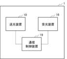
- FIG. 1 is a block diagram showing an example of a configuration of a communication device according to a first embodiment
- FIG. FIG. 2 is a conceptual diagram showing an example of the configuration of a light transmitting device included in the communication device according to the first embodiment
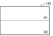
- FIG. 2 is a conceptual diagram showing an example of a modulation region assigned to a modulation section of a spatial light modulator of a light transmission device included in the communication device according to the first embodiment
- FIG. 2 is a conceptual diagram showing an example of a modulation region assigned to a modulation section of a spatial light modulator of a light transmission device included in the communication device according to the first embodiment
- FIG. 2 is a conceptual diagram showing an example of a modulation region assigned to a modulation section of a spatial light modulator of a light transmission device included in the communication device according to the first embodiment
- FIG. 2 is a conceptual diagram showing an example of a modulation region assigned to a modulation section of a spatial light modulator of a light transmission device included in the communication device according to the first embodiment
- FIG. 2 is a conceptual diagram showing an example of tiling of modulation regions assigned to modulation sections of a spatial light modulator of a light transmission device included in the communication device according to the first embodiment
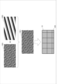
- FIG. 2 is a conceptual diagram showing an example of patterns set in modulation regions assigned to modulation sections of a spatial light modulator of a light transmitting device included in the communication device according to the first embodiment
- FIG. 4 is a conceptual diagram showing another example of a pattern set in a modulation area assigned to a modulation section of a spatial light modulator of a light transmitting device included in the communication device according to the first embodiment
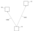
- FIG. 2 is a conceptual diagram for explaining optical space communication between communication devices according to the first embodiment
- FIG. 4 is a conceptual diagram for explaining the position of an image displayed by projection light transmitted by the communication device according to the first embodiment
- FIG. 2 is a conceptual diagram for explaining optical space communication between communication devices in Related Technology 1;
- FIG. 10 is a conceptual diagram for explaining the position of an image displayed by projection light transmitted by a communication device according to Related Art 1;
- FIG. 10 is a conceptual diagram for explaining optical space communication between communication devices in Related Technology 2;
- FIG. 10 is a conceptual diagram for explaining the position of an image displayed by projection light transmitted by a communication device according to Related Art 2;
- It is a block diagram showing an example of a light receiving device provided in the communication device according to the first embodiment.
- It is a block diagram showing an example of a light receiving device provided in the communication control device according to the first embodiment.
- FIG. 11 is a block diagram showing an example of the configuration of a communication device according to a second embodiment;
- FIG. 11 is a conceptual diagram showing an example of the configuration of a light transmitting device included in a communication device according to a second embodiment
- FIG. 11 is a conceptual diagram showing an example of assignment of modulation regions to modulation sections of a spatial light modulator of a light transmitting device included in a communication device according to a second embodiment
- FIG. 12 is a block diagram showing an example of the configuration of a communication device according to a third embodiment
- FIG. FIG. 11 is a conceptual diagram showing an example of a configuration of a light transmitting device included in a communication device according to a third embodiment
- FIG. 11 is a graph showing an example of energy distribution of an image displayed by projection light projected from a light transmitting device included in a communication device according to a third embodiment
- FIG. 11 is a conceptual diagram for explaining division of a projection range of projection light projected from a light transmitting device included in a communication device according to a third embodiment;
- FIG. 11 is a conceptual diagram for explaining an example of tiling of modulation regions assigned to modulation units of a spatial light modulator of a light transmission device included in a communication device according to a third embodiment;
- FIG. 11 is a conceptual diagram for explaining an example of power control of projected light by a light transmitting device included in a communication device according to a third embodiment;
- FIG. 11 is a conceptual diagram for explaining division of a projection range of projection light projected from a light transmitting device included in a communication device according to a third embodiment;
- FIG. 11 is a conceptual diagram for explaining an example of tiling of modulation regions assigned to modulation units of a spatial light modulator of a light transmission device included in a communication device according to a third embodiment;
- FIG. 11 is a conceptual diagram for explaining an example of power control of projected light by a light
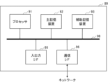
- 11 is a conceptual diagram for explaining another example of power control of projected light by a light transmitting device included in a communication device according to a third embodiment; It is a block diagram which shows an example of a structure of the light transmission apparatus which concerns on 4th Embodiment. It is a block diagram showing an example of hardware constitutions which realize control and processing concerning each embodiment.
- the communication device of this embodiment performs optical space communication for transmitting and receiving optical signals propagating in space (hereinafter also referred to as spatial optical signals) without using a medium such as an optical fiber.
- optical space communication is performed simultaneously with a plurality of communication targets.
- FIG. 1 is a block diagram showing an example of the configuration of a communication device 1 of this embodiment.
- the communication device 1 of this embodiment includes a light transmitting device 10 , a light receiving device 16 and a communication control device 19 .
- the light transmitting device 10, the light receiving device 16, and the communication control device 19 will be individually described below.
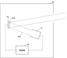
- FIG. 2 is a conceptual diagram showing an example of the configuration of the light transmitting device 10.
- the light transmitting device 10 includes a light source 11 , a spatial light modulator 13 and a controller 14 .
- the spatial light modulator 13 has a modulating section 130 .
- FIG. 2 is a lateral side view of the internal configuration of the light transmitting device 10. As shown in FIG. FIG. 2 is conceptual and does not accurately represent the positional relationship between components, the traveling direction of light, and the like.
- the position of the control unit 14 is not particularly limited.
- the control unit 14 may be included in the communication control device 19 .
- the light source 11 includes an emitter 111 and a lens 112.
- the emitter 111 emits laser light 101 in a predetermined wavelength band toward the lens 112 under the control of the controller 14 .
- Lens 112 is arranged on the optical path of laser light 101 emitted from emitter 111 .
- the lens 112 is arranged so that the laser beam 101 emitted from the emitter 111 is irradiated according to the size of the modulation section 130 of the spatial light modulator 13 .
- the lens 112 adjusts the irradiation range of the laser light 101 according to the size of the modulation section 130 of the spatial light modulator 13 .
- the light source 11 includes a single emitter 111 and lens 112 as an example. In practice, it is required to independently control the emitter 111 for each communication target. Therefore, the light source 11 is configured to include a plurality of emitters 111 and lenses 112 so that the number of communicable communication targets is the upper limit.
- the wavelength of the laser light 101 emitted from the emitter 111 is not particularly limited, and may be selected according to the application.
- the emitter 111 emits laser light 101 in the visible or infrared wavelength band.
- near-infrared rays of 800 to 900 nanometers (nm) can raise the laser class, so the sensitivity can be improved by about an order of magnitude compared to other wavelength bands.
- a high-output laser light source can be used for infrared rays in the wavelength band of 1.55 micrometers ( ⁇ m).
- An aluminum gallium arsenide phosphide (AlGaAsP)-based laser light source, an indium gallium arsenide (InGaAs)-based laser light source, or the like can be used as an infrared laser light source in a wavelength band of 1.55 ⁇ m.
- AlGaAsP aluminum gallium arsenide phosphide
- InGaAs indium gallium arsenide
- the spatial light modulator 13 has a modulating section 130 .
- a plurality of modulation regions are set in the modulation section 130 .
- Each of the plurality of modulation regions is associated with each of the plurality of communication targets.
- a pattern (phase image) for each spatial light signal transmitted to a communication target corresponding to each of the plurality of modulation regions is set in each of the plurality of modulation regions.
- Modulated light 103 (projection light 105) for each communication target is emitted from each of the plurality of modulation regions.
- the modulated light 103 (projection light 105) emitted from each of the plurality of modulation regions is displayed as a dot-like image (also referred to as a dot image) at the position of the communication target associated with each modulation region. .
- the spatial light modulator 13 is realized by a spatial light modulator using ferroelectric liquid crystal, homogeneous liquid crystal, vertically aligned liquid crystal, or the like.
- the spatial light modulator 13 can be realized by LCOS (Liquid Crystal On Silicon).
- the spatial light modulator 13 may be realized by a MEMS (Micro Electro Mechanical System).
- the phase modulation type spatial light modulator 13 the energy can be concentrated on the image portion by sequentially switching the location where the projection light 105 is projected. Therefore, when the phase modulation type spatial light modulator 13 is used, if the output of the light source 11 is the same, the image can be displayed brighter than other methods.
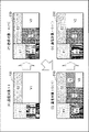
- FIG. 3 to 6 are conceptual diagrams showing examples of modulation regions set in the modulation section 130 of the spatial light modulator 13.
- FIG. A plurality of modulation regions are set in modulation section 130 in order to correspond to a plurality of communication targets.
- one example of the emitter 111 included in the light source 11 is shown. If the light source includes multiple emitters 111, the light 102 applied to multiple modulation regions can be independently controlled.
- FIG. 3 is an example in which two modulation areas (modulation area A1 and modulation area A2) are set in the modulation section 130.
- the modulation section 130 may be divided into at least two modulation regions as shown in FIG.
- FIG. 4 is an example in which three modulation regions (modulation region B1, modulation region B2, and modulation region B3) are set in the modulation section 130.
- the modulation section 130 may be divided into at least three modulation regions as shown in FIG.
- FIG. 5 is an example in which four modulation regions (modulation region C1, modulation region C2, modulation region C3, and modulation region C4) are set in the modulation section 130.
- the modulation section 130 may be divided into at least four modulation regions as shown in FIG.
- FIG. 6 is an example in which six modulation areas (modulation area D1, modulation area D2, modulation area D3, modulation area D4, modulation area D5, and modulation area D6) are set in the modulation section 130.
- the modulation section 130 may be divided into at least six modulation regions as shown in FIG.
- a phase image corresponding to the image formed by the projection light 105 projected toward the communication target is set in the modulation region associated with the communication target. For example, a phase image may not be set in a modulation region that is not associated with a communication target.
- FIG. 7 is a conceptual diagram for explaining the pattern (phase image) set in the modulation area 135 assigned to the modulation section 130 of the spatial light modulator 13.
- the modulation area 135 assigned to the modulation section 130 of the spatial light modulator 13 is divided into multiple areas (also called tiles 1350). For example, modulation region 135 is divided into square tiles 1350 of the desired aspect ratio.
- Each of the plurality of tiles 1350 is composed of a plurality of pixels.
- Each of the plurality of tiles 1350 set in the modulation area 135 is assigned a phase image 1300 of an image formed by the projection light 105 projected toward the communication target associated with the modulation area 135 .
- each of the plurality of tiles 1350 is set with a pre-generated phase image.
- Each of the plurality of tiles 1350 is set with a phase image 1300 corresponding to an image projected toward a communication target associated with the modulation region 135 including those tiles 1350 .
- each of the plurality of tiles 1350 is set with a phase image 1300 that displays a dot image at the position of the communication target. is assigned.
- a collection of phase images 1300 assigned to multiple tiles 1350 form a phase image 1301 .
- a phase image 1301 which is a set of phase images 1300 in which image information to be displayed on the projection target by the projection light 105 is written, is set in the modulation area 135 .
- FIG. 8 is a conceptual diagram showing an example of a pattern (phase image) set in the modulation section 130 of the spatial light modulator 13.
- FIG. A composite image 1351 of the phase image 1301 and the shift image 1302 is set in the modulation unit 130 .
- a phase image 1301 is a pattern for forming a desired image.
- the shift image 1302 is a pattern that two-dimensionally shifts the position of the image displayed by the projection light 105 using the phase image 1301 .
- the shift image 1302 is set so as to move the image according to the output profile of the modulated light 103 emitted from the modulation section 130 of the spatial light modulator 13 .
- the image displayed by the projection light using the phase image 1301 can be shifted in the horizontal direction or the vertical direction.
- a projection optical system such as a Fourier transform lens or a projection lens may be used.
- a synthetic image 1351 generated in advance may be stored in a storage unit (not shown).
- FIG. 8 is an example and does not limit the patterns of the phase image 1301, the shift image 1302, and the composite image 1351.
- FIG. 9 is a conceptual diagram showing another example of the pattern (phase image) set in the modulation section 130 of the spatial light modulator 13.
- FIG. FIG. 9 is an example using a virtual lens image.
- the wavefront of light like diffraction, can be controlled by phase control. When the phase changes spherically, there is a spherical difference in the wavefront and a lens effect occurs.
- the virtual lens image spherically changes the phase of the light 102 applied to the modulation unit 130 of the spatial light modulator 13 to generate a lens effect that converges light on a condensing point with a predetermined focal length.
- a projection optical system such as a Fourier transform lens and a projection lens can be omitted.
- the example in FIG. 9 is an example in which the modulation section 130 is divided into two upper and lower modulation regions as in FIG. 3 .
- FIG. 9 is a conceptual example and does not accurately represent patterns of virtual lens images, shift images, and phase images that are actually used.
- a composite image 1352A1 of the phase image 1301A1, the shift image 1302A1, and the virtual lens image 1303A1 is set in the upper modulation area (also referred to as the modulation area A1) of the modulation unit 130.
- the phase image 1301A1 and the shift image 1302A1 are set according to the modulation area A1.
- the virtual lens image 1303A1 is a pattern for condensing light that forms an image based on the phase image 1301A1 and the shift image 1302A1 to the focal point of the virtual lens image 1303A1.
- the virtual lens image 1303A1 is set according to the entire modulation section 130 .
- the portion overlapping the phase image 1301A1 and the shift image 1302A1 (the portion within the white dashed line) is used.
- a composite image 1352A2 of a phase image 1301A2, a shift image 1302A2, and a virtual lens image 1303A2 is set in a modulation area (also referred to as a modulation area A2) on the lower side of the modulation section 130.
- FIG. Phase image 1301A2 and shift image 1302A2 are set in accordance with modulation area A2.
- the virtual lens image 1303A2 is a pattern for condensing light that forms an image based on the phase image 1301A2 and the shift image 1302A2 to the focal point of the virtual lens image 1303A2.
- the virtual lens image 1303A2 is set according to the entire modulation section .
- the virtual lens image 1303A2 uses the portion overlapping the phase image 1301A2 and the shift image 1302A2 (the portion within the white dashed line).
- two modulation regions are set in the modulation section 130 .
- An arbitrary number of modulation regions can be set in the modulation section 130 .
- Individual composite images 1352 corresponding to the respective modulation regions are set in each of the plurality of modulation regions set in the modulation section 130 .
- a pattern such as a synthesized image 1351, a synthesized image 1352A, or a synthesized image 1352B is set in the modulation unit 130 and the light 102 is applied to the modulation unit 130, the modulation unit 130 of the spatial light modulator 13 , the modulated light 103 is emitted.
- modulated light 103 that forms an image corresponding to the phase image 1300 of each tile 1350 is emitted from the modulator section 130 of the spatial light modulator 13 .
- the more tiles 1350 set in the modulation unit 130 the clearer the image can be displayed.
- the resolution decreases. Therefore, the size and number of tiles 1350 set in the modulation section 130 are set according to the application.
- a plurality of modulation areas 135 are set in the modulation section 130 of the spatial light modulator 13 in association with a plurality of communication targets.
- a phase image corresponding to the image displayed by the projection light 105 projected on the associated communication target is set in each of the plurality of modulation regions 135 .
- Projection light 105 that displays images of the same shape may be projected onto each of the plurality of modulation regions 135 , or projection light 105 that displays images of different shapes may be projected.
- the control unit 14 controls the light source 11 and the spatial light modulator 13 according to the light transmission instruction acquired from the communication control device 19 .
- the controller 14 is implemented by a microcomputer including a processor and memory.
- the control unit 14 converts a phase image corresponding to the projected image into a plurality of modulation regions 135 assigned to the modulation unit 130 in accordance with the aspect ratio of the modulation regions set in the modulation unit 130 of the spatial light modulator 13. set to each of the
- the control unit 14 sets phase images corresponding to images suitable for optical space communication in each of the plurality of modulation regions 135 assigned to the modulation unit 130 .
- the phase image of the image to be projected may be stored in advance in a storage unit (not shown).
- the shape and size of the projected image are not particularly limited.
- the control unit 14 sets a pattern (phase image) corresponding to the image formed by the projection light 105 in the modulation unit 130 of the spatial light modulator 13 .
- the controller 14 sets a phase image for each tile assigned to the modulator 130 of the spatial light modulator 13 .
- the control unit 14 performs spatial light modulation such that the parameter that determines the difference between the phase of the light 102 irradiated to the modulation unit 130 of the spatial light modulator 13 and the phase of the modulated light 103 reflected by the modulation unit 130 is changed.
- a phase image is set in the modulator 130 by driving the device 13 .
- the parameter that determines the difference between the phase of the light 102 irradiated to the modulating section 130 of the spatial light modulator 13 and the phase of the modulated light 103 reflected by the modulating section 130 is an optical parameter such as a refractive index or an optical path length. It is a parameter related to characteristics.
- the control section 14 adjusts the optical characteristics of the modulation section 130 by changing the voltage applied to the modulation section 130 of the spatial light modulator 13 .
- the phase distribution of the light 102 irradiated to the modulating section 130 of the phase modulation type spatial light modulator 13 is modulated according to the optical characteristics of the modulating section 130 .
- a method of driving the spatial light modulator 13 by the controller 14 is determined according to the modulation method of the spatial light modulator 13 .
- the control unit 14 drives the emitter 111 of the light source 11 while the phase image corresponding to the displayed image is set in the modulation unit 130 .
- the control unit 14 drives the emitter 111 included in the light source 11 in synchronization with the timing of transmitting the spatial light signal.
- the light 102 emitted from the light source 11 is modulated by a plurality of modulations assigned to the modulation unit 130 of the spatial light modulator 13 in accordance with the timing at which the phase image is set in the modulation unit 130 of the spatial light modulator 13.
- Area 135 is illuminated.
- the light 102 irradiated onto each of the plurality of modulation regions 135 assigned to the modulation section 130 of the spatial light modulator 13 is modulated according to the phase image set on each of the plurality of modulation regions 135 .
- Modulated light 103 modulated by the modulation section 130 of the spatial light modulator 13 is projected as projection light 105 .
- a projection unit that enlarges and projects the modulated light 103 as the projected light 105 may be arranged on the optical path of the modulated light 103 .
- the projection section is realized by a projection optical system including a Fourier transform lens and a projection lens.
- the projection unit is realized by a curved mirror having a curved reflecting surface that magnifies and reflects the modulated light 103 . Description of the details of the projection unit is omitted.
- a shield may be arranged on the optical path of the modulated light 103 (projected light 105) to pass the modulated light 103 (projected light 105) forming a desired image and shield unnecessary light components.
- the shield shields zero-order light and ghost images contained in the modulated light 103 (projected light 105).
- the shield is an aperture with a slit-shaped opening in a portion that allows passage of light forming the desired image.
- the shield is a frame that shields unnecessary light components contained in the modulated light 103 (projection light 105) and defines the outer edge of the display area of the projection light 105.
- a zero-order light remover for removing zero-order light may be arranged on the optical path of the modulated light 103 (projected light 105).
- a zero order light remover includes a light absorbing member supported by a member that supports the light absorbing member.
- the light absorbing member is fixed on the optical path of the zero-order light included in the modulated light 103 (projected light 105) by the support member.
- the support member is made of a material such as glass or plastic through which the modulated light 103 (projected light 105) is transmitted.
- a black body such as carbon is used as the light absorbing member.
- FIG. 10 shows an example in which projection light 105 is projected from the light transmitting device 10 toward a plurality of communication devices 1 to be communicated.
- projection light 105B is projected from the communication device 1A toward the communication device 1B
- projection light 105C is projected toward the communication device 1C.
- the communication device 1B and the communication device 1C are located at different distances/directions from the communication device 1A.
- FIG. 11 is a conceptual diagram for explaining positions where pixels (dots) forming an image are displayed by projection light 105B and projection light 105C projected from the communication device 1A in the positional relationship of FIG.
- the projection light 105B and the projection light 105C are light modulated by phase images set in different modulation regions 135 assigned to the modulation section 130 of the spatial light modulator 13 of the communication device 1A.
- dashed-line squares ( ⁇ ) are shown at positions where dots are displayed by the projected light 105B
- broken-line diamonds ( ⁇ ) are shown at positions where dots are displayed by the projected light 105C.
- the communication device 1B is arranged at a position ( ⁇ ) where dots are displayed by the projection light 105B.
- the communication device 1B is irradiated with an image including the dots 106B.
- the communication device 1C is placed at a position ( ⁇ ) where dots are displayed by the projected light 105C. Therefore, the communication device 1C is irradiated with an image including the dots 106C.
- the area of dot 106B at the position of communication device 1B and the area of dot 106C at the position of communication device 1C are the same. Varies depending on
- an image including dots 106B displayed by projection light 105B projected from the communication device 1A is projected onto the communication device 1B but not projected onto the communication device 1C.
- an image including dots 106C displayed by projection light 105C projected from communication device 1A is irradiated to communication device 1C, but is not irradiated to communication device 1C.
- the spatial light signal can also be applied to the device 1 at the same time.
- Comparative Example 1 including the problem to be solved by the present embodiment will be described.
- Comparative Example 1 has a problem that spatial light signals cannot be simultaneously applied to a plurality of communication targets due to the positional relationship between the communication targets.
- FIG. 12 is a conceptual diagram showing a projection example of projection light in this comparative example.
- projection light 150 is projected from the communication device 100A toward the communication devices 100B and 100C.
- the communication device 100B and the communication device 100C are located at different distances/directions from the communication device 100A.
- the communication device 100A also includes a spatial light modulator (not shown) similar to that of this embodiment. However, only a single modulation region is set in the modulation section of the spatial light modulator of the communication device 100A.
- FIG. 13 is a conceptual diagram for explaining positions where pixels (dots) forming an image are displayed by projection light 150 projected from the communication device 100A in the positional relationship of FIG.
- the projected light 150 is light modulated by a phase image set in the modulation section of the spatial light modulator of the communication device 100A.
- dashed circles ( ⁇ ) are shown at positions where dots are displayed by the projection light 105B.
- the communication device 1B is placed at a position ( ⁇ ) where a dot is displayed by the projection light 105B. Therefore, the communication device 1B is irradiated with an image including the dot-shaped irradiation pattern 155 .
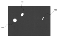
- the communication device 1C is not arranged at a position where dots are displayed by the projected light 105C. Therefore, the communication device 1C is not irradiated with an image including dots.
- the communication device 100B is irradiated with an image including the irradiation pattern 155 displayed by the projection light 150 projected from the communication device 100A, but the communication device 100C is not irradiated.
- the communication device 100C In order to stably perform optical space communication using spatial optical signals, it is required that a beam of accurate power be applied to an accurate position.
- a phase modulation type spatial light modulator is used, gaps are created between pixels. In Comparative Example 1, since the positions of the pixels forming the image displayed by the projected light 150 are fixed, the projected light 150 is not applied to the communication device 100C at the positions of the gaps between the pixels.
- FIG. 13 when the position of the irradiation pattern 155 is aligned with the communication device 1B, the communication device 1C is deviated from the irradiation position of the image including the irradiation pattern 155.
- FIG. 13 since a single modulation region is set in the modulation section 130 of the spatial light modulator 13, a situation may arise in which spatial light signals cannot be simultaneously transmitted to a plurality of communication devices 100. .
- Comparative Example 2 has a problem that when a plurality of communication targets are simultaneously irradiated with the spatial light signal, the intensity of the light irradiated to the communication targets becomes unstable.
- 14A and 14B are conceptual diagrams showing an example of projection light in Comparative Example 2.
- Communication device 100B, communication device 100C, and communication device 100D are located at different distances/directions from communication device 100A.
- the communication device 100A also includes a spatial light modulator (not shown) similar to that of this embodiment. However, only a single modulation region is set in the modulation section of the spatial light modulator of the communication device 100A.
- FIG. 15 is a conceptual diagram showing an example of images displayed at the positions of communication devices 100B, 100C, and 100D by projection light 150 projected from communication device 100A in the positional relationship of FIG. .
- the projected light 150 is light modulated by a phase image set in the modulation section of the spatial light modulator of the communication device 100A.
- a phase image is set in the modulation section of the spatial light modulator of the communication device 100A so that a circular (o) image (irradiation pattern 155) is displayed at the position of the communication device 100B.
- the communication device 100A projects projection light 150 that forms a circular (o) image (irradiation pattern 155) onto the communication device 100B.
- a distorted circular (elliptical) image is formed at the positions of the communication device 100C and the communication device 100D.
- the irradiation pattern 155 displayed by the projection light 150 is irradiated with different shapes/sizes at each position of the communication device 100B, the communication device 100C, and the communication device 100D.
- the irradiation pattern 155 emitted by each of the communication device 100B, the communication device 100C, and the communication device 100D varies depending on the area of the light source. (not shown) share the power of the laser light emitted from. For example, when communication with the communication device 100C is stopped, the power of the projection light 150 projected on the communication device 100B and the communication device 100D suddenly increases.
- FIG. 16 is a conceptual diagram for explaining the configuration of the light receiving device 16.
- the light receiving device 16 includes a collector 161 , a light receiving element 17 and a receiving circuit 18 .
- FIG. 16 shows an example in which the light receiving element 17 is single. It is more practical for the light receiving device 16 to be configured to include a plurality of light receiving elements 17 .
- FIG. 16 is a plan view of the internal configuration of the light receiving device 16 as viewed from above. Note that the position of the receiving circuit 18 is not particularly limited.
- the receiving circuit 18 may be arranged inside the light receiving device 16 or may be arranged outside the light receiving device 16 . Also, the function of the receiving circuit 18 may be included in the communication control device 19 .
- the light collector 161 is an optical element that collects spatial light signals coming from the outside.
- a spatial light signal is incident on the incident surface of the collector 161 .
- the optical signal condensed by the condenser 161 is condensed toward the area where the light receiving element 17 is arranged.
- collector 161 is a lens that collects the incident spatial light signal.
- the light collector 161 is a light beam control element that guides the incident spatial light signal toward the light receiving section 170 of the light receiving element 17 .
- the condenser 161 may have a configuration in which a lens and a light beam control element are combined.
- the configuration of the light collector 161 is not particularly limited as long as the spatial light signal can be collected toward the area where the light receiving element 17 is arranged.
- a mechanism for guiding the optical signal condensed by the concentrator 161 toward the light receiving portion 170 of the light receiving element 17 may be added.
- the light receiving element 17 receives light in the wavelength region of the spatial light signal to be received.
- the light receiving element 17 has sensitivity to light in the visible region.
- the light receiving element 17 has sensitivity to light in the infrared region.
- the light receiving element 17 is sensitive to light with a wavelength in the 1.5 ⁇ m (micrometer) band, for example.
- the wavelength band of light to which the light receiving element 17 is sensitive is not limited to the 1.5 ⁇ m band.
- the wavelength band of the light received by the light receiving element 17 can be arbitrarily set according to the wavelength of the spatial light signal to be received.
- the wavelength band of light received by the light receiving element 17 may be set to, for example, 0.8 ⁇ m band, 1.55 ⁇ m band, or 2.2 ⁇ m band.
- the wavelength band of light received by the light receiving element 17 may be, for example, the 0.8 to 1 ⁇ m band.
- the shorter the wavelength band the smaller the absorption by moisture in the atmosphere, which is advantageous for optical free-space communication during rainfall.
- a color filter for selectively passing light in the wavelength band of the spatial light signal may be installed before the light receiving element 17 .
- a polarizing plate may be provided in front of the light receiving element 17 to selectively pass the spatial light signal in the polarization state to be received.
- a band-pass filter that selectively passes the spatial optical signals in the wavelength band to be received may be installed before the light receiving element 17 .
- the light receiving element 17 can be realized by an element such as a photodiode or a phototransistor.
- the light receiving element 17 is realized by an avalanche photodiode.
- the light-receiving element 17 realized by an avalanche photodiode can handle high-speed communication.
- the light-receiving element 17 may be realized by elements other than photodiodes, phototransistors, and avalanche photodiodes as long as they can convert optical signals into electrical signals. In order to improve the communication speed, it is preferable that the light receiving portion of the light receiving element 17 is as small as possible.
- the light-receiving portion of the light-receiving element 17 has a square light-receiving surface with a side of about 5 mm (millimeters).
- the light receiving portion of the light receiving element 17 has a circular light receiving surface with a diameter of approximately 0.1 to 0.3 mm.
- the size and shape of the light receiving portion of the light receiving element 17 may be selected according to the wavelength band of the spatial light signal, communication speed, and the like.
- the receiving circuit 18 acquires the signal output from each of the light receiving elements 17 .
- the receiving circuit 18 amplifies the signal from each of the light receiving elements 17 .
- the receiving circuit 18 decodes the amplified signal and analyzes the signal from the communication target.
- the signal decoded by receiving circuit 18 is used for any purpose. Use of the signal decoded by the receiving circuit 18 is not particularly limited.
- FIG. 17 is a block diagram for explaining an example of the configuration of the communication control device 19.
- the communication control device 19 has a condition storage unit 191 , a light transmission condition generation unit 192 , a light transmission instruction unit 193 , a signal acquisition unit 195 , a signal analysis unit 196 and a signal generation unit 197 .
- the communication control device 19 is implemented by a microcomputer including a processor and memory.
- the communication control device 19 may be implemented in a server or cloud connected to the light transmitting device 10 and the light receiving device 16 via a network.
- the condition storage unit 191 stores patterns such as a phase image, a shift image, and a virtual lens image corresponding to the projection light 105 transmitted by the light transmission device 10 .
- the patterns stored in the condition storage section 191 are set in the modulation section 130 of the spatial light modulator 13 .
- the condition storage unit 191 also stores projection conditions including light source control conditions for controlling the light source 11 of the light transmitting device 10 and modulator control conditions for controlling the spatial light modulator 13 of the light transmitting device 10. do.
- the light source control condition is a condition including the timing for emitting the laser beam 101 from the light source 11 of the light transmitting device 10 .
- a modulator control condition is a condition for setting a pattern in the modulation section 130 of the spatial light modulator 13 . By coordinating the light source control condition and the modulator control condition, the projection light 105 is projected according to the pattern set in the modulation section 130 of the spatial light modulator 13 .
- the light transmission condition generator 192 acquires the signal from the signal generator 197 . Based on the conditions stored in the condition storage unit 191, the light transmission condition generation unit 192 generates light transmission conditions for transmitting information included in the acquired signal. For example, the light transmission condition generation unit 192 selects a pattern for transmitting information included in the acquired signal based on the projection conditions stored in the condition storage unit 191 . For example, the light transmission condition generation unit 192 generates a light transmission condition for setting a pattern corresponding to a projected image to the modulation unit 130 of the spatial light modulator 13 in order to transmit the information included in the acquired signal. do. For example, the light transmission condition generation unit 192 modulates the phase image corresponding to the image to be projected according to the aspect ratio of the modulation area set in the modulation unit 130 of the spatial light modulator 13. A light transmission condition to be set in the unit 130 is generated.
- the light transmission instruction unit 193 Based on the light transmission conditions set by the light transmission condition generation unit 192, the light transmission instruction unit 193 issues light transmission instructions to the light transmission device 10 for controlling the light source 11 and the spatial light modulator 13 of the light transmission device 10. output to
- the signal acquisition unit 195 acquires the signal decoded by the light receiving device 16 from the light receiving device 16 . Further, the signal acquisition unit 195 acquires from the light receiving device 16 the signal that has undergone signal processing by the light receiving device 16 .
- the signal acquired by the signal acquisition unit 195 includes a scanned communication target and a response transmitted from a communication target during communication according to the spatial light signal transmitted from the communication device 1 .
- the signal acquisition section 195 outputs the acquired signal to the signal analysis section 196 .
- the signal analysis unit 196 analyzes the signal acquired by the signal acquisition unit 195 .
- the signal analysis unit 196 analyzes information included in the signal according to the signal type.
- the types of signals include scan signals and communication signals.
- the type of signal analyzed by the signal analysis unit 196 is not particularly limited.
- the signal analysis unit 196 outputs the signal analysis result to the signal generation unit 197 .
- the signal generation unit 197 acquires the analysis result of the signal by the signal analysis unit 196 .
- the signal generator 197 generates a transmission signal according to the signal analysis result.
- the transmission signal includes communication content with the communication target and content used for scanning the communication target.
- the signal generator 197 generates a transmission signal for each communication target.
- the signal generator 197 generates scan signals and communication signals as transmission signals.
- a scan signal is a signal used for scanning a communication target.
- a communication signal is a signal containing information exchanged with a communication target.
- the signal generator 197 outputs the generated signal to the light transmission condition generator 192 .
- a communication signal is a signal transmitted and received between communication devices 1 with which communication is established when a communication path for transmitting and receiving spatial light signals is established.
- a communication signal includes information to be transmitted to a communication target.
- the information to be put on the communication signal may be predetermined content, or may be content according to the information included in the communication signal from the communication target.
- the information included in the communication signal transmitted from the communication target is displayed on a display device (not shown).
- an operator confirming the information displayed on the display device inputs a response to the displayed information to the communication control device 19 (signal generator 197) via an input device (not shown).
- the signal generator 197 generates a communication signal including the input information.
- Information to be included in the communication signal is not particularly limited.
- the communication device of this embodiment includes a light transmitting device, a light receiving device, and a communication control device.
- a light receiving device receives a spatial light signal transmitted from a communication target.
- the receiver decodes signals contained in the received spatial light signal.
- a communication control device acquires the signal decoded by the light receiving device.
- the communication control device causes the light transmitting device to transmit a spatial light signal corresponding to the acquired signal.
- the light transmitting device has a light source, a spatial light modulator, and a controller.
- the light source emits light.
- the spatial light modulator has a modulating section irradiated with light emitted from a light source.
- the spatial light modulator modulates the phase of irradiated light at the modulation section.
- the control unit allocates modulation regions associated with each of the plurality of communication targets to the modulation unit of the spatial light modulator.
- the control unit sets, in the modulation area, a phase image for forming an image used in communication with the communication target at the position of the communication target.
- the control unit sets a phase image for displaying an image at the position of the communication target associated with each of the plurality of modulation regions, in each of the plurality of modulation regions assigned to the modulation unit of the spatial light modulator. .
- the control unit controls the light source so that the light is emitted to the modulation unit to which the phase image is set.
- a modulation region for each communication target is set in the modulation section of the spatial light modulator in association with each of a plurality of communication targets.
- a phase image for each communication target is set in the modulation area.
- a modulation region for each communication target is set in the modulation section, so that a stable spatial optical signal can be transmitted to a plurality of communication targets.
- control unit displays an image in each of the plurality of modulation regions assigned to the modulation unit of the spatial light modulator at the communication target position associated with each of the plurality of modulation regions.
- a phase image is set for each of a plurality of communication targets.
- the control unit sets a composite image of the phase image and the shift image in each of the plurality of modulation regions assigned to the modulation unit of the spatial light modulator.
- a phase image is a pattern for displaying an image.
- a shift image is a pattern for changing the display position of an image (for example, a dot image) at a communication target position associated with each of a plurality of modulation regions. According to this aspect, by using the shift image, the display position of the image can be changed to any position within the projection range.
- the control unit sets a composite image of the phase image, the shift image, and the virtual lens image in each of the plurality of modulation regions assigned to the modulation unit of the spatial light modulator.
- a phase image is a pattern for displaying an image.
- a shift image is a pattern for changing the display position of an image (for example, a dot image) at a communication target position associated with each of a plurality of modulation regions.
- a virtual lens image is a pattern for enlarging and projecting an image.
- the shift image can be used to change the display position of the image to any position within the projection range.
- the display position of the image can be changed to any position within the projection range.
- the image can be enlarged and projected by using the virtual lens image.
- the communication apparatus of this embodiment differs from the first embodiment in dynamically changing the modulation region assigned to the modulation section of the spatial light modulator.
- FIG. 18 is a block diagram showing an example of the configuration of the communication device 2 of this embodiment.
- the communication device 2 of this embodiment includes a light transmitting device 20 , a light receiving device 26 and a communication control device 29 .
- the light receiving device 26 and the communication control device 29 are the same as the corresponding configurations of the first embodiment. In the following, description of the light receiving device 26 and the communication control device 29 will be omitted, and the configuration of the light transmitting device 20 will be described in detail.
- an example in which the light transmission conditions of the spatial optical signal are set by the light transmission device 20 will be given.
- the light transmission conditions of the spatial light signal may be set by the communication control device 29 .
- FIG. 19 is a conceptual diagram showing an example of the configuration of the light transmitting device 20.
- the light transmitting device 20 includes a light source 21 , a spatial light modulator 23 and a controller 24 .
- the spatial light modulator 23 has a modulating section 230 .
- FIG. 19 is a lateral side view of the internal configuration of the light transmitting device 20. As shown in FIG. FIG. 19 is conceptual, and does not accurately represent the positional relationship between each component, the traveling direction of light, and the like.
- the position of the control unit 24 is not particularly limited.
- the control unit 24 may be included in the communication control device 29 .
- the light source 21 and the spatial light modulator 23 are similar to the corresponding configurations of the first embodiment.
- the control unit 24 has the same configuration as the corresponding configuration in the first embodiment except for the method of allocating modulation regions to the modulation unit 230 of the spatial light modulator 23 .
- the method of allocating modulation regions to the modulation section 230 of the spatial light modulator 23 by the control section 24 will be focused on.
- FIG. 20 is a conceptual diagram for explaining a method of allocating modulation regions to the modulation section 130 of the spatial light modulator 13.
- the control unit 24 allocates at least one modulation region to the modulation unit 230 according to the number of communication targets.
- the control unit 24 sets at least one spare region (also referred to as a spare region) that is not assigned to a communication target. For example, in the preliminary area, a pattern (phase image) is set in which the modulated light 203 is not emitted according to the irradiation of the light 202 .
- (E) of FIG. 20 is an example of allocation of modulation regions when there are three communication targets.
- the control section 24 sets the modulation area E1, the modulation area E2, the modulation area E3, and the preliminary area V1 in the modulation section 230.
- FIG. A modulation area E1, a modulation area E2, a modulation area E3, and a spare area V1 are set in the modulation section 230 .
- Modulation area E1, modulation area E2, and modulation area E3 are modulation areas associated with any communication target.
- the spare area V1 is a spare area that is not assigned to any communication target.
- (F) of FIG. 20 is an example of allocation of modulation regions when the number of communication targets increases from three to four.
- the control unit 24 divides the preliminary area V1 into the modulation area F and the preliminary area V2.
- a modulation area E1, a modulation area E2, a modulation area E3, a modulation area F, and a spare area V2 are set in the modulation section .
- Modulation area E1, modulation area E2, modulation area E3, and modulation area F are modulation areas associated with any communication target.
- the spare area V2 is a spare area that is not assigned to any communication target.
- (G) of FIG. 20 is an example of allocation of modulation regions when the number of communication targets increases from four to five.
- the control unit 24 divides the preliminary area V2 into the modulation area G and the preliminary area V3.
- a modulation area E1, a modulation area E2, a modulation area E3, a modulation area F, a modulation area G, and a preliminary area V3 are set in the modulation section .
- Modulation area E1, modulation area E2, modulation area E3, modulation area F, and modulation area G are modulation areas associated with any communication target.
- the spare area V3 is a spare area that is not assigned to any communication target.
- (H) of FIG. 20 is an example of allocation of modulation regions when the number of communication targets is reduced from five to four.
- the control unit 24 integrates the modulation area G and the preliminary area V3 to set the preliminary area V2.
- the spare area V2 is the same area as (F) in FIG.
- a modulation area E1, a modulation area E2, a modulation area E3, a modulation area F, and a spare area V2 are set in the modulation section .
- Modulation area E1, modulation area E2, modulation area E3, and modulation area F are modulation areas associated with any communication target.
- the spare area V2 is a spare area that is not assigned to any communication target.
- the control unit 24 dynamically changes the number of modulation regions assigned to the modulation unit 230 of the spatial light modulator 23 according to an increase or decrease in the number of communication targets.
- the control unit 24 sets a spare region that is not assigned to a communication target.
- the control unit 24 sets a new modulation region as a spare region according to an increase in the number of communication targets.
- the control unit 24 integrates one of the modulation regions into the spare region according to the decrease in the number of communication targets. In other words, the control unit 24 increases or decreases the number of modulation regions set in the spare regions of the modulation unit 230 of the spatial light modulator 23 according to an increase or decrease in the number of communication targets.
- control unit 24 can change the number of modulation regions assigned to the modulation unit 230 of the spatial light modulator 23 for each projecting opportunity of the projection light 205 .
- control section 24 may change the area of the modulation region according to the output profile of the modulated light 203 emitted from the modulation section 230 of the spatial light modulator 23 .
- control unit 24 sets the area of each of the plurality of modulation regions so that the power of each of the plurality of modulation regions becomes uniform according to the output profile.
- the communication device of this embodiment includes a light transmitting device, a light receiving device, and a communication control device.
- a light receiving device receives a spatial light signal transmitted from a communication target.
- the receiver decodes signals contained in the received spatial light signal.
- a communication control device acquires the signal decoded by the light receiving device.
- the communication control device causes the light transmitting device to transmit a spatial light signal corresponding to the acquired signal.
- the light transmitting device has a light source, a spatial light modulator, and a controller.
- the light source emits light.
- the spatial light modulator has a modulating section irradiated with light emitted from a light source.
- the spatial light modulator modulates the phase of irradiated light at the modulation section.
- the control unit allocates modulation regions associated with each of the plurality of communication targets to the modulation unit of the spatial light modulator.
- the control unit sets, in the modulation area, a phase image for forming an image used in communication with the communication target at the position of the communication target.
- the control unit dynamically varies the number of modulation regions assigned to the modulation unit of the spatial light modulator according to the number of communication targets.
- the control unit controls the light source so that the light is emitted to the modulation unit to which the phase image is set.
- a modulation area is set for each communication target in the modulation section of the spatial light modulator. Therefore, if the number of modulation regions is fixed, communication with a new communication target cannot be established when all modulation regions are used.
- the number of modulation regions assigned to the modulation unit of the spatial light modulator is dynamically varied according to the number of communication targets in association with each of the communication targets. Therefore, according to the present embodiment, since a situation in which the modulation region cannot be used is unlikely to occur, continuous optical space communication can be realized with a plurality of communication targets.
- control unit sets a spare area that is not used for communication with the communication target in the modulation unit. According to this aspect, by setting a spare area that is not used for communication and dynamically allocating a modulation area to the spare area, it is possible to flexibly cope with communication conditions.
- control unit dynamically allocates part of the spare area as a modulation area in accordance with an increase in the number of communication targets. According to this aspect, when the number of communication targets increases, it is possible to realize continuous optical space communication with a plurality of communication targets by dynamically allocating modulation regions to spare regions.
- control unit integrates modulation regions that are no longer used for communication with communication targets into spare regions in response to a decrease in the number of communication targets. If the modulation areas not used for communication are set as they are, power may be wasted due to the unused modulation areas. According to this aspect, when the number of communication targets decreases, the power consumption of the spatial light modulator can be optimized by integrating the modulation area that is no longer used for communication into the spare area.
- the communication device of this embodiment differs from the first and second embodiments in that the tiling of the modulation area set in the modulation unit is adjusted according to the output profile of the image displayed in the projection range. .
- the technique of this embodiment may be combined with the technique of the second embodiment.
- FIG. 21 is a block diagram showing an example of the configuration of the communication device 2 of this embodiment.
- the communication device 3 of this embodiment includes a light transmitting device 30 , a light receiving device 36 and a communication control device 39 .
- the light receiving device 36 and the communication control device 39 are the same as the corresponding configurations of the first embodiment. In the following, description of the light receiving device 36 and the communication control device 39 will be omitted, and the configuration of the light transmitting device 30 will be described in detail.
- an example in which the light transmission conditions of the spatial optical signal are set by the light transmission device 30 will be given.
- the light transmission condition of the spatial light signal may be set by the communication control device 39 .
- FIG. 22 is a conceptual diagram showing an example of the configuration of the light transmitting device 30.
- the light transmitting device 30 includes a light source 31 , a spatial light modulator 33 and a controller 34 .
- the spatial light modulator 33 has a modulating section 330 .
- FIG. 22 is a lateral side view of the internal configuration of the light transmitting device 30. As shown in FIG. FIG. 22 is conceptual, and does not accurately represent the positional relationship between each component, the traveling direction of light, and the like.
- the position of the control unit 34 is not particularly limited.
- the control unit 34 may be included in the communication control device 39 .
- the light source 31 and the spatial light modulator 33 are similar to the corresponding configurations of the first embodiment.
- the control unit 34 has the same configuration as the corresponding configuration of the first embodiment except for the tiling method in the modulation unit 330 of the spatial light modulator 33 .
- the following description will focus on the tiling method in the modulation section 330 of the spatial light modulator 33 by the control section 34 .
- FIG. 23 is an example of an energy distribution (also called an output profile) of an image (dot image) formed on the projection surface by the projection light 305.
- FIG. The horizontal axis of the graph in FIG. 23 indicates the position on the projection surface.
- the vertical axis of the graph in FIG. 23 indicates the power of the dot image displayed by the projection light 305 for each position on the projection surface.
- FIG. 23 shows a one-dimensional energy distribution on a straight line passing through the center of the projection range.
- An actual output profile shows a two-dimensional energy distribution.
- the actual output profile shows an energy distribution centered at the center of the projection range and distributed concentrically.
- the output profile of the dot image on the projected surface shows non-linear power distribution.
- the output profile of the dot image on the projection surface changes depending on the projection optical system for projecting the projection light 305.
- FIG. For example, if a mechanism for removing the 0th-order light contained in the projection light 305 is introduced, a dot image is not displayed at the projection position of the 0th-order light, so a power-applied profile in the central portion of the projection range can be obtained.
- the dot image has the maximum power when displayed in the center of the projection range. The power of the dot image decreases as it moves away from the center of the projection range. That is, the power of the dot image formed on the projection surface is not uniform within the projection surface.
- the power of the dot image on the projection surface is not uniform, the output of the spatial light signal used for communication with the communication target will not be stable. Stable communication cannot be continued unless the output of the spatial light signal is stable. In order to continue stable communication, it is preferable that the power of the dot image is as flat as possible within the plane of the projection surface.
- the power EP of the dot image can be estimated by the relationship between the power W, the output profile P, the phase image factor PF, and the number N of tiles.
- the output W is the output of the light 302 emitted from the light source 31 and applied to the modulation section 330 of the spatial light modulator 33 .
- the output profile P is the power of the dot image for each position on the projection surface.
- the phase image factor PF includes various factors.
- the phase image factor PF includes a factor related to the brightness of the phase image.
- the phase image factor PF includes factors related to the normalized value of the illumination light used when generating the phase image.
- the phase image factor PF is a factor relating to the presence or absence and shape of the noise sweep area set when generating the phase image.
- the number of tiles N is the number of tiles per modulation region.
- the power EP of the projected light 305 can be expressed by the relationship shown in Equation 1 below.
- P W ⁇ P ⁇ F ⁇ N (1)
- the phase image factor PF it is difficult to uniform the power of the dot image over the entire area of the projected surface. Therefore, in this embodiment, the phase image factor PF and the number of tiles N are combined to adjust the power of the dot image on the projection surface.
- the number N of tiles used to form the dot image is important. If the number of tiles N is small, the dot image will be degraded. Therefore, in this embodiment, the number N of tiles is set to be increased while keeping the resolution of the tiles low.
- the phase images are set in a plurality of tiles included in the modulation area assigned to the modulation unit 330 of the spatial light modulator 33, and the phase images are assigned to the modulation area.
- FIG. 24 is a conceptual graph for explaining an example of dot image power control by the light transmitting device 30 .
- the graph in FIG. 24 shows the output profile of the dot image formed on the projection surface by the projection light 305.
- the output profile of FIG. 24 is similar to the output profile of FIG.
- the graph of FIG. 24 illustrates the target value of the power of the dot image.
- the power target value is set according to the class of laser light used for spatial optical communication. For example, assuming a class 1 visible light laser, the power target value is set to about 0.39 watts. For example, assuming a class 1 1.5 micrometer band infrared light laser, the power target value is set to about 10 milliwatts.
- the projected surface is one-dimensionally divided into five regions on a straight line passing through the center of the projected surface.
- the projection surface is divided into five areas (area a, area b, area c, area d, and area e).
- the two-dimensional projected surface is divided into regions in a grid.
- the light transmitting device 30 sets, for each region, a phase image in which the lower limit of the output profile is the target power value. As can be seen in the output profile, the power of the dot image decreases away from the center of the projected surface. Therefore, a phase image is set to display a brighter dot image in a region further away from the center of the projection range. On the other hand, a phase image is set to display a darker dot image in a region closer to the center of the projection range. A phase image for displaying a dot image in each area decreases the number of tiles set in the modulation area as the center of the projection surface is approached within the range of each area.
- FIG. 25 is a conceptual diagram showing an example of reducing the number of tiles set in the modulation area assigned to the modulation section 330 of the spatial light modulator 33.
- the modulation region includes multiple tiles.
- a phase image for displaying a dot image on the projection surface is displayed on each of the plurality of tiles.
- the same phase image is set for a plurality of tiles included in the same modulation area.
- a phase image 3301 is a pattern set in the modulation area.
- a phase image 3301 is composed of a phase image set for each of a plurality of tiles included in the modulation area.
- a phase image 3302 in FIG. 25 is an example in which the number of tiles (active tiles) used for displaying dot images is reduced.
- Light 302 irradiated to tiles not used for displaying dot images (also called inactive tiles) is not converted into modulated light 303 and contributes to zero-order light.
- Inactive tiles are not reflected in the display of dot images displayed on the projection surface. Even if the number of active tiles is reduced, the displayed dot image is the same. Therefore, by reducing the number of active tiles, the power of the dot image can be reduced without changing the displayed dot image. In other words, the power of the dot image can be adjusted by adjusting the number of tiles used to display the dot image.
- the power of the dot image is maximized when the phase image is set for all of the multiple tiles included in the modulation area. Therefore, the power of the dot image displayed by the projection light 305 projected with the phase image set for all the tiles is set as the target value of the power of the dot image displayed in each region.
- a phase image is set for all tiles included in the modulation area in order to display the dot image at the farthest position from the center of the projection range. As the display position of the dot image is closer to the center of the projection range, the power of the dot image in each area can be brought closer to the target value by reducing the number of tiles used for displaying the dot image.
- FIG. 26 is a conceptual diagram for explaining an example of dot image power control.
- FIG. 26 is an enlarged view of regions a and b in FIG.
- the light transmitting device 30 transmits a phase image for displaying a dot image showing power equivalent to the target power value at the left end point of the area a to the modulation area assigned to the modulation unit 330 of the spatial light modulator 33. set.
- the phase image set in the modulation area is shifted so that the position of the dot image moves toward the center of the projection range, the power increases as indicated by the dotted line according to the trend of the output profile. go.
- the area a the power increases from the left end to the right end of the area a.
- the power of the dot image in the area a can be kept constant. can.
- the output profile intersects the power target value within the region a. Therefore, with respect to the position where the output profile and the target value of power intersect, a phase image showing power equivalent to the target value of power should be set in the modulation area.
- the number of tiles in the modulation region may be reduced so that the power of the dot image approaches the target value.
- the number of tiles in the modulation area may be reduced in accordance with the position of the projection range, similarly to the area b.
- the phase image for displaying the dot image showing the power equivalent to the target value of the power at the point on the right end of the area e is modulated by the modulation unit 330 of the spatial light modulator 33.
- the power decreases according to the tendency of the output profile.
- region e the power decreases from the left end to the right end of region e.
- FIG. 27 is a conceptual diagram for explaining another example of dot image power control.
- FIG. 27 is an enlarged view of regions a and b in FIG.
- the light transmitting device 30 sets a phase image showing power equivalent to the target power value at the leftmost point of the area a in the modulation area assigned to the modulation section 330 of the spatial light modulator 33 .
- the phase image set in the modulation area is shifted so that the position of the dot image moves toward the center of the projection range, the power increases as indicated by the dotted line according to the trend of the output profile. go.
- the power of the dot image in the area a can be kept constant. can.
- the number of tiles in the modulation area is reduced so that the power of the dot image approaches the target value over the entire area a.
- the power of the dot image in the region b may be controlled so as to approach the target value.
- a table may be prepared in which the number of inactive tiles is associated with the position of the projection range.
- the light transmitting device 30 can set the number of inactive tiles according to the position where the dot image is to be displayed.
- the position of the inactive tile in the modulation area can be set arbitrarily.
- a table may be prepared in which tiled phase images of active tiles and inactive tiles are associated with positions in the projection range.
- a phase image tiled with active and inactive tiles contains a number of active tiles depending on the power of the dot image.
- the light transmitting device 30 can set the phase image in which the inactive tiles are patterned according to the position where the dot image is to be displayed.
- the position of the inactive tile in the modulation area can be set arbitrarily.
- a map in which tiled phase images of active tiles and inactive tiles are mapped may be prepared for the positions of the projection range.
- a phase image tiled with active and inactive tiles contains a number of active tiles depending on the power of the dot image.
- the light transmitting device 30 may select the phase image from the map according to the position where the dot image is to be displayed.
- the position of the inactive tile in the modulation area can be set arbitrarily.
- the communication device of this embodiment includes a light transmitting device, a light receiving device, and a communication control device.
- a light receiving device receives a spatial light signal transmitted from a communication target.
- the receiver decodes signals contained in the received spatial light signal.
- a communication control device acquires the signal decoded by the light receiving device.
- the communication control device causes the light transmitting device to transmit a spatial light signal corresponding to the acquired signal.
- the light transmitting device has a light source, a spatial light modulator, and a controller.
- the light source emits light.
- the spatial light modulator has a modulating section irradiated with light emitted from a light source.
- the spatial light modulator modulates the phase of irradiated light at the modulation section.
- the control unit allocates modulation regions associated with each of the plurality of communication targets to the modulation unit of the spatial light modulator.
- the control unit sets, in the modulation area, a phase image for forming an image used in communication with the communication target at the position of the communication target.
- the control unit adjusts the phase images set in the plurality of tiles assigned to the modulation area according to the projection position of the image in the projection range so that the power of the image displayed in the projection range of the image approaches a target value. change.
- the control unit controls the light source so that the light is emitted to the modulation unit to which the phase image is set.
- the power of the image displayed in the projection range varies depending on the position inside the projection range.
- the power of the image displayed in the projection range is adjusted to the target value by changing the phase images set in the plurality of tiles assigned to the modulation area according to the projection position of the image in the projection range. bring closer. Therefore, according to this embodiment, the image displayed in the projection range can be smoothed. That is, according to this aspect, it is possible to stabilize the power of the spatial light signal irradiated to the communication target.
- control unit sets one of the plurality of tiles assigned to the modulation region as an inactive tile for which no phase image is set.
- the control unit adjusts the number of inactive tiles according to the projection position of the image in the projection range so that the power of the image displayed in the projection range approaches a target value.
- the power of the projected image can be adjusted by changing the number of tiles that constitute the modulation area.
- control unit changes the phase images set in the plurality of tiles assigned to the modulation area for each area set inside the projection range.
- the power of the image to be projected can be adjusted by setting a phase image for each region set inside the projection range.
- FIG. 28 is a conceptual diagram showing an example of the configuration of the light transmitting device 40 of this embodiment.
- Light transmitting device 40 includes light source 41 and spatial light modulator 43 .
- the light source 41 emits light 402 .
- the spatial light modulator 43 has a modulating section 430 irradiated with the light 402 emitted from the light source 41 .
- the spatial light modulator 43 modulates the phase of the irradiated light 402 with the modulator 430 .
- the control unit 44 allocates modulation regions associated with each of a plurality of communication targets to the modulation unit 430 of the spatial light modulator 43 .
- the control unit 44 sets, in the modulation area, a phase image for forming an image used in communication with the communication target at the position of the communication target.
- the control unit 44 controls the light source 41 so that the light 402 is applied to the modulation unit 430 set with the phase image.
- a modulation region for each communication target is set in the modulation section of the spatial light modulator in association with each of a plurality of communication targets.
- a phase image for each communication target is set in the modulation area.
- a modulation region for each communication target is set in the modulation section, so that a stable spatial optical signal can be transmitted to a plurality of communication targets.
- the information processing device 90 includes a processor 91, a main storage device 92, an auxiliary storage device 93, an input/output interface 95, and a communication interface 96.
- the interface is abbreviated as I/F (Interface).
- Processor 91 , main storage device 92 , auxiliary storage device 93 , input/output interface 95 , and communication interface 96 are connected to each other via bus 98 so as to enable data communication.
- the processor 91 , the main storage device 92 , the auxiliary storage device 93 and the input/output interface 95 are connected to a network such as the Internet or an intranet via a communication interface 96 .
- the processor 91 loads the program stored in the auxiliary storage device 93 or the like into the main storage device 92 .
- the processor 91 executes programs developed in the main memory device 92 .
- a configuration using a software program installed in the information processing device 90 may be used.
- the processor 91 executes control and processing according to this embodiment.
- the main storage device 92 has an area in which programs are expanded.
- a program stored in the auxiliary storage device 93 or the like is developed in the main storage device 92 by the processor 91 .
- the main memory device 92 is realized by a volatile memory such as a DRAM (Dynamic Random Access Memory). Further, as the main storage device 92, a non-volatile memory such as MRAM (Magnetoresistive Random Access Memory) may be configured/added.
- the auxiliary storage device 93 stores various data such as programs.
- the auxiliary storage device 93 is implemented by a local disk such as a hard disk or flash memory. It should be noted that it is possible to store various data in the main storage device 92 and omit the auxiliary storage device 93 .
- the input/output interface 95 is an interface for connecting the information processing device 90 and peripheral devices based on standards and specifications.
- a communication interface 96 is an interface for connecting to an external system or device through a network such as the Internet or an intranet based on standards and specifications.
- the input/output interface 95 and the communication interface 96 may be shared as an interface for connecting with external devices.
- Input devices such as a keyboard, mouse, and touch panel may be connected to the information processing device 90 as necessary. These input devices are used to enter information and settings.
- a touch panel is used as an input device, the display screen of the display device may also serve as an interface of the input device. Data communication between the processor 91 and the input device may be mediated by the input/output interface 95 .
- the information processing device 90 may be equipped with a display device for displaying information.
- the information processing device 90 is preferably provided with a display control device (not shown) for controlling the display of the display device.
- the display device may be connected to the information processing device 90 via the input/output interface 95 .
- the information processing device 90 may be equipped with a drive device. Between the processor 91 and a recording medium (program recording medium), the drive device mediates reading of data and programs from the recording medium, writing of processing results of the information processing device 90 to the recording medium, and the like.
- the drive device may be connected to the information processing device 90 via the input/output interface 95 .
- the above is an example of the hardware configuration for enabling control and processing according to each embodiment of the present invention.
- the hardware configuration of FIG. 29 is an example of a hardware configuration for executing control and processing according to each embodiment, and does not limit the scope of the present invention.
- the scope of the present invention also includes a program that causes a computer to execute control and processing according to each embodiment.
- the scope of the present invention also includes a program recording medium on which the program according to each embodiment is recorded.
- the recording medium can be implemented as an optical recording medium such as a CD (Compact Disc) or a DVD (Digital Versatile Disc).
- the recording medium may be implemented by a semiconductor recording medium such as a USB (Universal Serial Bus) memory or an SD (Secure Digital) card.
- the recording medium may be realized by a magnetic recording medium such as a flexible disk, or other recording medium.
- each embodiment may be combined arbitrarily. Also, the components of each embodiment may be realized by software or by circuits.
- (Appendix 1) a light source; a spatial light modulator having a modulating section to which light emitted from the light source is irradiated, wherein the modulating section modulates the phase of the irradiated light; A modulation region associated with each of a plurality of communication targets is assigned to the modulation unit of the spatial light modulator, and a phase image for forming an image used in communication with the communication target at the position of the communication target is generated. and a control unit configured to control the light source so that the light is emitted to the modulation unit set in the modulation area and to which the phase image is set.
- (Appendix 2) The control unit The phase image for displaying the image at each of the plurality of modulation regions assigned to the modulation section of the spatial light modulator at the position of the communication target associated with each of the plurality of modulation regions.
- the light transmitting device according to Supplementary Note 1, wherein (Appendix 3)
- the control unit The phase image for displaying the image at each of the plurality of modulation regions assigned to the modulation section of the spatial light modulator at the position of the communication target associated with each of the plurality of modulation regions. is set for each of the plurality of communication targets.
- the control unit a synthesized image obtained by synthesizing the phase image for displaying the image and a shift image for changing the display position of the image at the position of the communication target associated with each of the plurality of modulation regions; 4.
- the light transmitting device according to any one of appendices 1 to 3, wherein each of the plurality of modulation regions assigned to the modulation section of the spatial light modulator is set.
- the control unit The phase image for displaying the image, the shift image for changing the display position of the image at the position of the communication target associated with each of the plurality of modulation regions, and projecting the image in an enlarged manner. 4.
- the transmitter according to any one of appendices 1 to 3, wherein a synthesized image synthesized with a virtual lens image for is set in each of the plurality of modulation areas assigned to the modulation unit of the spatial light modulator.
- light device (Appendix 6) The control unit 6. The light transmission according to any one of appendices 1 to 5, wherein the number of the plurality of modulation regions assigned to the modulation unit of the spatial light modulator is dynamically varied according to the number of the plurality of communication targets.
- Device (Appendix 7) The control unit 7. The light transmitting device according to appendix 6, wherein a spare area that is not used for communication with the communication target is set in the modulation section.
- the control unit The light transmitting device according to appendix 7, wherein part of the spare area is dynamically allocated as the modulation area in accordance with an increase in the number of communication targets.
- the control unit 9 The light transmitting device according to appendix 7 or 8, wherein the modulation area that is no longer used for communication with the communication target is integrated into the spare area according to the decrease in the number of communication targets.
- the control unit The phases set in the plurality of tiles assigned to the modulation area according to the projection position of the image in the projection range so that the power of the image displayed in the projection range of the image approaches a target value. 10.
- a light transmission device according to any one of claims 1 to 9 for modifying an image.
- Appendix 13 the light transmitting device according to any one of Appendices 1 to 12; a light receiving device that receives a spatial optical signal transmitted from a communication target and decodes a signal included in the received spatial optical signal; a communication control device that acquires the signal decoded by the light receiving device and causes the light transmitting device to transmit a spatial light signal corresponding to the acquired signal.
- a control method for a light transmission device including a spatial light modulator that modulates the phase of light emitted from a light source by a modulation unit, the computer Allocating a modulation region associated with each of a plurality of communication targets to the modulation unit of the spatial light modulator; setting a phase image in the modulation region for forming an image used in communication with the communication target at the position of the communication target; A control method for controlling the light source so that the light is emitted to the modulation unit in which the phase image is set.
- a program for controlling a light transmitting device comprising a spatial light modulator that modulates the phase of light emitted from a light source with a modulating unit, a process of assigning a modulation region associated with each of a plurality of communication targets to the modulation unit of the spatial light modulator; A process of setting, in the modulation area, a phase image for forming an image used in communication with the communication target at the position of the communication target; A program for causing a computer to execute a process of controlling the light source so that the light is emitted to the modulation unit in which the phase image is set.
Landscapes
- Physics & Mathematics (AREA)
- Engineering & Computer Science (AREA)
- Signal Processing (AREA)
- Electromagnetism (AREA)
- Computer Networks & Wireless Communication (AREA)
- Optics & Photonics (AREA)
- Nonlinear Science (AREA)
- General Physics & Mathematics (AREA)
- Multimedia (AREA)
- Optical Communication System (AREA)
Priority Applications (3)
| Application Number | Priority Date | Filing Date | Title |
|---|---|---|---|
| US18/689,577 US20240380493A1 (en) | 2021-09-21 | 2021-09-21 | Optical transmission device, communication device, control method and recording medium |
| PCT/JP2021/034501 WO2023047444A1 (ja) | 2021-09-21 | 2021-09-21 | 送光装置、通信装置、制御方法、および記録媒体 |
| JP2023549178A JP7622858B2 (ja) | 2021-09-21 | 2021-09-21 | 送光装置、通信装置、制御方法、およびプログラム |
Applications Claiming Priority (1)
| Application Number | Priority Date | Filing Date | Title |
|---|---|---|---|
| PCT/JP2021/034501 WO2023047444A1 (ja) | 2021-09-21 | 2021-09-21 | 送光装置、通信装置、制御方法、および記録媒体 |
Publications (1)
| Publication Number | Publication Date |
|---|---|
| WO2023047444A1 true WO2023047444A1 (ja) | 2023-03-30 |
Family
ID=85720217
Family Applications (1)
| Application Number | Title | Priority Date | Filing Date |
|---|---|---|---|
| PCT/JP2021/034501 Ceased WO2023047444A1 (ja) | 2021-09-21 | 2021-09-21 | 送光装置、通信装置、制御方法、および記録媒体 |
Country Status (3)
| Country | Link |
|---|---|
| US (1) | US20240380493A1 (https=) |
| JP (1) | JP7622858B2 (https=) |
| WO (1) | WO2023047444A1 (https=) |
Citations (3)
| Publication number | Priority date | Publication date | Assignee | Title |
|---|---|---|---|---|
| US20080056723A1 (en) * | 2005-08-09 | 2008-03-06 | Randy Clinton Giles | Multiple access free space laser communication method and apparatus |
| JP2011061267A (ja) * | 2009-09-07 | 2011-03-24 | Osaka Univ | 光無線通信用送信装置 |
| WO2017169913A1 (ja) * | 2016-03-29 | 2017-10-05 | 日本電気株式会社 | 通信装置および通信方法 |
-
2021
- 2021-09-21 US US18/689,577 patent/US20240380493A1/en active Pending
- 2021-09-21 JP JP2023549178A patent/JP7622858B2/ja active Active
- 2021-09-21 WO PCT/JP2021/034501 patent/WO2023047444A1/ja not_active Ceased
Patent Citations (3)
| Publication number | Priority date | Publication date | Assignee | Title |
|---|---|---|---|---|
| US20080056723A1 (en) * | 2005-08-09 | 2008-03-06 | Randy Clinton Giles | Multiple access free space laser communication method and apparatus |
| JP2011061267A (ja) * | 2009-09-07 | 2011-03-24 | Osaka Univ | 光無線通信用送信装置 |
| WO2017169913A1 (ja) * | 2016-03-29 | 2017-10-05 | 日本電気株式会社 | 通信装置および通信方法 |
Also Published As
| Publication number | Publication date |
|---|---|
| JP7622858B2 (ja) | 2025-01-28 |
| US20240380493A1 (en) | 2024-11-14 |
| JPWO2023047444A1 (https=) | 2023-03-30 |
Similar Documents
| Publication | Publication Date | Title |
|---|---|---|
| JP4158987B2 (ja) | 2次元画像形成装置 | |
| TWI546609B (zh) | Light irradiation device | |
| JP5315711B2 (ja) | 照明装置及び画像投影装置 | |
| WO2012014690A1 (ja) | プロジェクタ | |
| WO2019116526A1 (ja) | 投射装置、インターフェース装置および投射方法 | |
| JP7622858B2 (ja) | 送光装置、通信装置、制御方法、およびプログラム | |
| US20250141548A1 (en) | Communication control device, communication device, communication control method, and recording medium | |
| JP7613557B2 (ja) | 投射装置および投射方法 | |
| JP7688927B2 (ja) | イメージ分割基盤の光検出システム及び方法 | |
| JP7613556B2 (ja) | 投射装置および投射方法 | |
| JP7683704B2 (ja) | 受信装置、通信装置、および通信システム | |
| US12063459B2 (en) | Light transmitting device, communication system, and light transmitting method | |
| US20240353745A1 (en) | Projection device, projection control method, and recording medium | |
| WO2022137777A1 (ja) | 投射装置および投射方法 | |
| US12284466B2 (en) | Projection device, control method, and recording medium | |
| WO2023047448A1 (ja) | 通信制御装置、通信装置、通信制御方法、および記録媒体 | |
| US20240171286A1 (en) | Light reception device, reception device, and communication device | |
| JP7559961B2 (ja) | 送光装置および通信装置 | |
| JP7589824B2 (ja) | 投射装置および通信装置 | |
| US20240056192A1 (en) | Transmitter, transmission device, communication device, and communication system | |
| JP7673815B2 (ja) | 受信制御装置、受光装置、通信装置、受信制御方法、およびプログラム | |
| US20240283537A1 (en) | Transmitter, transmission device, communication device, and communication system | |
| US20240396636A1 (en) | Communication device and communication system | |
| WO2023047446A1 (ja) | 受信装置および通信装置 | |
| KR20150078713A (ko) | Led 패턴 조명부가 구비되는 광학 현미경 |
Legal Events
| Date | Code | Title | Description |
|---|---|---|---|
| 121 | Ep: the epo has been informed by wipo that ep was designated in this application |
Ref document number: 21958322 Country of ref document: EP Kind code of ref document: A1 |
|
| WWE | Wipo information: entry into national phase |
Ref document number: 2023549178 Country of ref document: JP |
|
| NENP | Non-entry into the national phase |
Ref country code: DE |
|
| 122 | Ep: pct application non-entry in european phase |
Ref document number: 21958322 Country of ref document: EP Kind code of ref document: A1 |