WO2023047439A1 - 回転機コイル、その製造方法および回転機 - Google Patents
回転機コイル、その製造方法および回転機 Download PDFInfo
- Publication number
- WO2023047439A1 WO2023047439A1 PCT/JP2021/034492 JP2021034492W WO2023047439A1 WO 2023047439 A1 WO2023047439 A1 WO 2023047439A1 JP 2021034492 W JP2021034492 W JP 2021034492W WO 2023047439 A1 WO2023047439 A1 WO 2023047439A1
- Authority
- WO
- WIPO (PCT)
- Prior art keywords
- layer
- mica
- rotating machine
- coil
- thickness direction
- Prior art date
- Legal status (The legal status is an assumption and is not a legal conclusion. Google has not performed a legal analysis and makes no representation as to the accuracy of the status listed.)
- Ceased
Links
Images




Classifications
-
- H—ELECTRICITY
- H02—GENERATION; CONVERSION OR DISTRIBUTION OF ELECTRIC POWER
- H02K—DYNAMO-ELECTRIC MACHINES
- H02K3/00—Details of windings
- H02K3/32—Windings characterised by the shape, form or construction of the insulation
-
- H—ELECTRICITY
- H02—GENERATION; CONVERSION OR DISTRIBUTION OF ELECTRIC POWER
- H02K—DYNAMO-ELECTRIC MACHINES
- H02K3/00—Details of windings
- H02K3/30—Windings characterised by the insulating material
-
- H—ELECTRICITY
- H02—GENERATION; CONVERSION OR DISTRIBUTION OF ELECTRIC POWER
- H02K—DYNAMO-ELECTRIC MACHINES
- H02K15/00—Processes or apparatus specially adapted for manufacturing, assembling, maintaining or repairing of dynamo-electric machines
- H02K15/10—Applying solid insulation to windings, stators or rotors, e.g. applying insulating tapes
- H02K15/104—Insulating between conductors
-
- H—ELECTRICITY
- H02—GENERATION; CONVERSION OR DISTRIBUTION OF ELECTRIC POWER
- H02K—DYNAMO-ELECTRIC MACHINES
- H02K15/00—Processes or apparatus specially adapted for manufacturing, assembling, maintaining or repairing of dynamo-electric machines
- H02K15/12—Impregnating, moulding insulation, heating or drying of windings, stators, rotors or machines
- H02K15/122—Impregnating, moulding insulation, heating or drying of windings, stators, rotors or machines of windings
-
- H—ELECTRICITY
- H02—GENERATION; CONVERSION OR DISTRIBUTION OF ELECTRIC POWER
- H02K—DYNAMO-ELECTRIC MACHINES
- H02K3/00—Details of windings
- H02K3/32—Windings characterised by the shape, form or construction of the insulation
- H02K3/34—Windings characterised by the shape, form or construction of the insulation between conductors or between conductor and core, e.g. slot insulation
-
- H—ELECTRICITY
- H02—GENERATION; CONVERSION OR DISTRIBUTION OF ELECTRIC POWER
- H02K—DYNAMO-ELECTRIC MACHINES
- H02K3/00—Details of windings
- H02K3/32—Windings characterised by the shape, form or construction of the insulation
- H02K3/40—Windings characterised by the shape, form or construction of the insulation for high voltage, e.g. affording protection against corona discharges
-
- H—ELECTRICITY
- H02—GENERATION; CONVERSION OR DISTRIBUTION OF ELECTRIC POWER
- H02K—DYNAMO-ELECTRIC MACHINES
- H02K3/00—Details of windings
- H02K3/46—Fastening of windings on the stator or rotor structure
- H02K3/48—Fastening of windings on the stator or rotor structure in slots
- H02K3/487—Slot-closing devices
Definitions
- This application relates to a rotating machine coil, its manufacturing method, and a rotating machine.
- a large rotating machine used for a turbine generator or the like has a stator coil housed in a plurality of slots formed on the inner peripheral side of a stator core.
- the stator coil consists of a metallic conductor and an insulating material disposed around it.
- Various processes are used to form this insulating material. For example, a mica tape made by laminating a fiber reinforcing material such as glass cloth to mica is wound several times around the stator coil conductor, and a low-viscosity liquid thermosetting resin is applied.
- a method of impregnating under reduced pressure followed by heat pressing (vacuum pressure impregnation method), and a method of placing a semi-cured resin on an insulating tape, winding this tape around the stator coil conductor and then heat-pressing it (resin Rich method) and the like.
- Rotating machines manufactured using such a process are increasingly required to be smaller and more efficient.
- Patent Document 1 discloses an insulating structure covering the outer surface of an object to be insulated to electrically insulate the object, wherein the surface of the object is a main insulating layer that extends planarly along the main insulating layer; a fiber reinforced portion that spreads along the main insulating layer; and a molecular polymer portion, wherein nanoparticles are scattered in the high molecular polymer portion, the concentration of the nanoparticles is highest in the fiber reinforced portion, and the nanoparticles are scattered in the high molecular polymer portion.
- An insulating structure is disclosed in which the withstand voltage characteristic is improved from the viewpoint of the insulation life of the insulating material, that is, the long-term reliability.
- nanoparticles nanoparticles
- electrical tree which is a phenomenon of electrical breakdown progression. Since electric trees progress over time in the electric field used in equipment, suppressing their progress is effective in improving the life of the insulation. On the other hand, if insulating materials are made thinner in order to make equipment smaller and more efficient, the electric field strength to the insulating material will increase. An improvement in the dielectric breakdown voltage of the material is required.
- Patent Document 1 In the configuration of the insulating structure of Patent Document 1, there is a description about the addition of nano fillers effective for improving long-term withstand voltage characteristics, but short-term dielectric breakdown and long-term dielectric breakdown phenomena differ in breakdown progression behavior. In Patent Document 1, short-term withstand voltage characteristics cannot be obtained, and there is a problem that it is not possible to meet the demand for miniaturization and high efficiency of equipment.
- the present application was made to solve the above-mentioned problems, and in order to realize miniaturization and high efficiency of equipment, a rotating machine coil equipped with an insulating material that has excellent short-term and long-term voltage resistance , a manufacturing method thereof and a rotating machine.
- a coil conductor, scale-like mica particles stacked in the thickness direction from the coil conductor side, and a film layer are laminated in this order, and a mica tape wound around the outer periphery of the coil conductor. and an insulating layer containing a cured product of a thermosetting resin composition impregnated in the scaly mica particles stacked in the thickness direction, wherein the scaly mica particles stacked in the thickness direction include the The dielectric constant of the inner layer side of the mica layer impregnated with the cured product is higher than the dielectric constant of the outer layer side of the mica layer.
- the method for manufacturing a rotating machine coil disclosed in the present application comprises a step of winding a fiber layer around the outer periphery of a coil conductor, and scaly mica particles and a film layer stacked in the thickness direction from the coil conductor side.
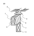
- FIG. 2 is a perspective schematic diagram enlarging a part of the stator of the rotating machine in which the rotating machine coil according to the first embodiment is incorporated; 3 is a schematic cross-sectional view of an insulating layer of the rotating machine coil according to Embodiment 1.
- FIG. FIG. 4 is a diagram showing a dispersed state of nano-fillers in the insulating layer of the rotating machine coil according to Embodiment 1;
- FIG. 4 is a flow chart diagram showing a manufacturing process of the rotating machine coil according to Embodiment 1;
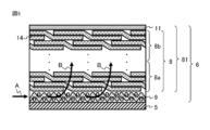
- FIG. 4 is a schematic diagram showing impregnation routes of the resin composition in the manufacturing process of the rotating machine coil according to Embodiment 1;
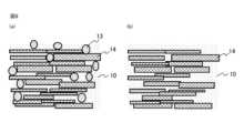
- FIG. 5 is a schematic diagram showing a dispersed state of nano-fillers in an insulating layer of another rotating machine coil according to Embodiment 1;
- FIG. 5 is a schematic diagram showing a dispersed state of nano-fillers in an insulating layer of another rotating machine coil according to Embodiment 1;
- FIG. 5 is a schematic diagram showing a dispersed state of nano-fillers in an insulating layer of another rotating machine coil according to Embodiment 1;
- FIG. 7 is a schematic cross-sectional view showing the configuration of a rotating machine according to Embodiment 2;
- FIG. 7 is a schematic cross-sectional view showing the configuration of a rotating machine according to Embodiment 2;
- FIG. 1 is a schematic perspective view showing an enlarged part of a stator of a rotating machine incorporating a rotating machine coil 1 according to Embodiment 1.
- FIG. 1 in the stator of the rotating machine, the rotating machine coils 1 are accommodated in two stages inside the slots 3 of the stator core 2 .
- a spacer 7 is inserted between the two stages of the rotating machine coil 1 , and a wedge 4 for fixing the rotating machine coil 1 is inserted into the opening end of the slot 3 .
- the wedge 4 has the effect of suppressing electromagnetic vibration generated from the rotating machine coil 1 during operation of the rotating machine.
- the rotating machine coil 1 has a coil conductor 5 and an insulating layer 6 covering the coil conductor 5 . Since the outer periphery of the coil conductor 5 is covered with the insulating layer 6, insulation from the stator core 2 is ensured.
- the cross-sectional shape of the coil conductor 5 is rectangular. As the coil conductor 5, a bundle of a plurality of metal wires each having a rectangular cross section can be used.
- the rotating machine coil 1 of the present application is characterized in that an insulating layer including a mica layer containing mica and resin is arranged on the outer periphery of the metal conductor, and the dielectric constant of the inner layer side of the mica layer is higher than that of the outer layer side. More specifically, in the rotating machine coil 1 of the present application, a fiber layer as a coil insulating material, a mica layer containing mica and a resin, and a film layer are arranged in this order around the outer periphery of the metal conductor, and the dielectric constant of the inner layer side of the mica layer is is higher than the outer layer side of the mica layer.
- the insulating layer of a coil is arranged around a prismatic metal conductor, so the electric field applied to the insulating layer is not uniform, and increases in the inner layers of the insulating layer, especially around the corners of the metal conductor. Tend. Therefore, dielectric breakdown tends to progress from this corner as a starting point.
- the dielectric constant of mica is in the range of 4-7, and the dielectric constant of the cured resin is in the range of 3-5.
- the mica filling rate on the inner layer side of the mica layer may be higher than that on the outer layer side, or the resin filling rate on the outer layer side may be higher than that on the inner layer side.
- FIG. 2 is a schematic cross-sectional view of the insulating layer of the rotating machine coil 1 according to the first embodiment.
- the insulating layer 6 includes a fiber layer 9 wound around the outer circumference of the coil conductor 5, a mica tape 81 wound around the outer circumference of the fiber layer 9, and the fiber layer 9 and the mica tape 81 stacked in the thickness direction. and a cured product 10 of a thermosetting resin composition impregnated with scale-like mica particles 14 .
- the mica tape 81 is composed of the scale-like mica particles 14 and the film layer 11 which are stacked in the thickness direction.
- the hardened material 10 consists of the impregnated region of the first mica layer 8a on the coil conductor 5 side (the range of 1/2 or less of the thickness of the mica layer 8) and the second mica layer on the outer peripheral side of the first mica layer 8a.
- the impregnated region of the layer 8b (a range exceeding 1/2 of the thickness of the mica layer 8) contains a nano-filler whose dispersion state is controlled.
- FIG. 3 is a diagram showing the dispersion state of nanofillers in the insulating layer of the rotating machine coil 1 according to Embodiment 1.
- FIG. 3A is a sectional view showing the inner layer side of the mica layer 8
- FIG. 3B is a sectional view showing the outer layer side of the mica layer 8.
- FIG. 3(a) the impregnation region of the first mica layer 8a on the inner layer side contains two types of nano-fillers 13 and 15 having different particle sizes.
- the impregnated region of the second mica layer 8b on the outer layer side contains only the nano-fillers 15 having a particle size smaller than that of the nano-fillers 13.
- FIG. 3(a) the impregnation region of the first mica layer 8a on the inner layer side contains two types of nano-fillers 13 and 15 having different particle sizes.
- FIG. 3(b) the impregnated region of the second mica layer 8b on the outer layer side contains only the nano-fillers 15 having a particle size smaller than that of the nano
- FIG. 4 is a flow chart showing manufacturing steps in the method for manufacturing the rotating machine coil 1 according to the first embodiment.
- the fiber layer 9 is wound around the outer circumference of the coil conductor 5 (step S401).
- the fiber layer 9 is formed of a non-woven fabric or fabric made of insulating fibers. Examples of such materials include glass cloth, glass nonwoven fabric, and resin nonwoven fabric. Among them, glass cloth is preferable because it is excellent in resin impregnability and has a reinforcing effect of mechanical strength.
- the mica tape 81 is wound around the outer periphery of the fiber layer 9 (step S402).
- the mica tape 81 is composed of the scale-like mica particles 14 and the film layer 11 which are stacked in the thickness direction.
- the film layer 11 is made of resin in the form of a sheet or tape, and must be insoluble in the liquid resin. Examples of materials for such a film layer 11 include polyethylene film, polypropylene film, acrylic film, and fluorine-containing film.
- the mica tape 81 is impregnated with a thermosetting resin composition (step S403).
- the fiber layer 9 has a higher resin impregnation coefficient than the scaly mica particles 14 stacked in the thickness direction, and the resin is more easily impregnated than the gaps of the mica tape 81.
- a resin permeation path is formed from the central portion of the coil to the inner layer side of the scale-like mica particles 14 stacked in the thickness direction to the outer layer side.
- thermosetting resin composition is cured while being impregnated in the mica tape 81 (step S404).
- the thermosetting resin composition is cured by heating at a temperature of 90° C. to 180° C. for 6 to 30 hours under normal pressure. Through such steps, the rotating machine coil 1 according to the first embodiment can be manufactured.
- FIG. 5 is a diagram showing impregnation paths of the thermosetting resin composition in the scale-like mica particles 14 stacked in the thickness direction in the manufacturing process of the rotating machine coil 1 according to the first embodiment.
- the thermosetting resin composition is impregnated from the end of the fiber layer 9 inward (direction A) through the fiber layer 9, and then in the thickness direction (B direction) of the mica particles 14 on the inner layer side. direction), and finally in the thickness direction (direction B) of the mica particles 14 on the outer layer side. Since the film layer 11 impermeable to resin is arranged outside the mica particles 14 , the impregnation of the thermosetting resin composition ends at the film layer 11 .
- thermosetting resin composition when a coil having an insulating layer wound with mica tape is impregnated with a liquid thermosetting resin composition, the thermosetting resin composition impregnates the insulating layer from the outer layer side to the inner layer side. be Alternatively, it is impregnated from the gap at the end of the mica tape of the insulating layer to the center side.
- the fiber layer 9 has a higher resin impregnation coefficient than the scaly mica particles 14 stacked in the thickness direction, and the thermosetting resin is greater than the gaps of the scaly mica particles 14 stacked in the thickness direction of the mica tape 81 . Since the composition is easily impregnated, a resin permeation path is formed from the inner layer side to the outer layer side of the scaly mica particles 14 stacked in the thickness direction through the fiber layer 9 . By controlling the dispersed state of the nano-filler contained in the thermosetting resin composition through this resin permeation path, it is possible to realize that the dielectric constant of the inner layer side of the mica layer 8 is higher than that of the outer layer side.
- the fiber layer 9 is characterized by having a higher resin impregnation coefficient than the scale-like mica particles 14 stacked in the thickness direction as described above. Therefore, an example of a method for measuring the resin impregnation coefficient will be described.
- the impregnation behavior of the substrate follows Darcy's law, and the following impregnation rate formula (1) is shown.
- v (K/ ⁇ ) ⁇ ( ⁇ P/ ⁇ L) (1)
- v is the impregnation speed (m/s)
- K is the resin impregnation coefficient (m 2 )
- ⁇ is the resin viscosity (Pa s)
- ⁇ P/ ⁇ L is the pressure gradient per unit length (Pa/m).
- L is the distance (m) from the resin impregnation port to the tip of the impregnated resin
- P the pressure (Pa) applied during impregnation.
- the impregnation coefficient can be calculated from the distance from the resin impregnation port to the tip distance, the arrival time, the resin viscosity, and the molding pressure. In general, this measurement obtains the resin impregnation coefficient K by measuring the impregnation coefficient with respect to the base material arranged in the form of a flat plate. In the present application, it is desirable that the resin impregnation coefficient ratio calculated from the fiber layer/the scale-like mica particles stacked in the thickness direction is 2 or more.
- nano-fillers 13 and 15 are combined with the liquid thermosetting resin composition and impregnated through the resin permeation path, the nano-fillers 13 and 15 are stacked in the thickness direction from the end of the fiber layer 9 through the fiber layer 9. It is impregnated into the scaly mica particles 14 that have been formed.
- the nano fillers 13 and 15 permeate the mica tape 81 in the thickness direction, when the nano fillers 13 and 15 permeate the mica tape 81 in the thickness direction, , the nano-fillers 13 and 15 are stochastically captured in the gaps between the mica particles 14, and a concentration gradient of the nano-fillers occurs in the thickness direction of the scaly mica particles 14 stacked in the thickness direction from the fiber layer 9. was newly found in the present application.
- the nanofiller 13 preferably has an average primary particle size of 70 nm or more and 500 nm or less, and the nanofiller 15 preferably has an average primary particle size of 60 nm or less and 10 nm or more.
- the nano-filler 13 is dispersed and remains in the first mica layer 8a due to the filtration phenomenon by the first mica layer 8a on the inner layer side of the mica layer 8, the nano-filler 15 is not filtered, and the nano-filler 15 on the inner layer side of the mica layer 8 It is dispersed uniformly over the entire area of the one mica layer 8a and the second mica layer 8b on the outer layer side.
- the average primary particle size of the nanofiller can be measured with a scanning electron microscope (SEM).
- SEM scanning electron microscope
- the nanofiller was randomly extracted and observed, the absolute particle size of 100 or more nanofillers was measured, and the average value of the measured values was used. It can be easily confirmed by the median diameter (50% diameter, D50), and as a measuring method, a laser diffraction scattering method particle size distribution device (for example, product name: Microtrac model: MT3300) may be used. be.
- the dielectric constant is higher than the cured product 10 of the thermosetting resin composition, and more preferably mica dielectric It is preferable that the dielectric constant of the nano-fillers 13 and 15 is 7 or more. In the mica layer 8 using these materials, the dielectric constant of the inner layer side is higher than that of the outer layer, which is effective in improving the withstand voltage. In particular, when the dielectric constant ratio (inner layer dielectric constant/outer layer dielectric constant) is controlled to 1.2 or more, the voltage resistance can be enhanced more effectively.
- Materials for the nanofillers 13 and 15 include silica, aluminum oxide, magnesium oxide, boron nitride, aluminum nitride, magnesium hydroxide, calcium carbonate, and magnesium carbonate.
- the cured product 10 of the thermosetting resin composition is preferably epoxy resin, phenol resin, silicone resin, or imide resin from the viewpoint of heat resistance, adhesiveness, electrical insulation, and mechanical strength, and among these, epoxy resin is particularly desirable.
- Specific epoxy resins include those containing an epoxy group in the skeleton, bisphenol A type epoxy resin, bisphenol F type epoxy resin, bisphenol S type epoxy resin, biphenol type epoxy resin, phenol novolak type epoxy resin, cresol novolak type epoxy resin.
- One type of resin may be used, or two or more types may be used.
- a reaction product of epichlorohydrin and a bisphenol A compound in view of the balance between cost, viscosity and heat resistance.
- reaction products include EPIKOTE (trademark) 828, EPIKOTE (trademark) 825 (trade name: above, manufactured by Yuka Shell Epoxy Co., Ltd.), Epotoot (trademark) YD128 (trade name: Tohto Kasei ( Ltd.), Epiclon (trademark) 850 (trade name: manufactured by Dainippon Ink and Chemicals, Inc.), Sumiepoxy (trademark) ELA-128 (trade name: manufactured by Sumitomo Chemical Co., Ltd.), and the like.
- epoxy resin containing three or more epoxy groups in the molecule is used alone or in combination with the above epoxy resin. good too.
- Epoxy resins containing three or more epoxy groups in the molecule include resorcinol diglycidyl ether (1,3-bis-(2,3-epoxypropoxy)benzene), diglycidyl ether of bisphenol A (2,2-bis( p-(2,3-epoxypropoxy)phenyl)propane), triglycidyl p-aminophenol (4-(2,3-epoxypropoxy)-N,N-bis(2,3-epoxypropyl)aniline), bromo Diglycidyl ether of bisphenol A (2,2-bis(4-(2,3-epoxypropoxy)3-bromo-phenyl)propane), diglycidyl ether of bisphenol F (2,2-bis(p-(2, 3-epoxypropoxy)phenyl)methane), triglycidyl ethers of meta- and/or para-aminophenol (3-(2,3-epoxypropoxy)N,N-bis(2,3
- the dielectric constant of the layer on the inner layer side (first mica layer 8a) of the mica layer 8 in which the hardened material 10 is impregnated with the mica particles 14 of the shape is the same as the layer on the outer layer side of the mica layer 8 (second mica layer 8b ), the electric field intensity applied to the insulating layer can be lowered to improve not only the long-term withstand voltage characteristics but also the short-term withstand voltage characteristics. It is possible to achieve high efficiency and efficiency.
- FIGS. 6 to 8 are diagrams showing how nanofillers are dispersed in other insulating layers of the rotating machine coil 1 according to Embodiment 1.
- the impregnation region of the mica layer 8a on the inner layer side contains only nano-fillers 13 (FIG. 6(a)), and the impregnation region of the mica layer 8b on the outer layer side contains nano-fillers. There may be no case (FIG. 6(b)).
- the impregnated region of the mica layer 8a on the inner layer side contains the nano-filler 15 at a high filling rate (FIG. 7(a)), and the impregnated region of the mica layer 8b on the outer layer side contains nano fillers 15. It may be the case that the filler 15 is contained at a lower filling rate than the inner layer side (FIG. 7(b)).
- Such a configuration has a wide particle size distribution of the nanofiller, an average primary particle size of 70 nm or more, and a nanofiller of 60 nm or less in a range of less than 50% of the total number of nanofillers. It is formed.
- the two types of nanofillers 13 and 15 having different particle diameters in Embodiment 1 differ in material (FIG. 8(a))
- the impregnated region of the mica layer 8b on the outer layer side may contain only the nano-filler 15 having a smaller particle size than the nano-filler 13 (FIG. 8(b)).
- three or more types of nanofillers may be used in combination, and each may have a different particle size distribution.
- FIG. 9 is a cross-sectional schematic cross-sectional view along the rotating shaft of the rotating machine 20 according to Embodiment 2.
- FIG. 10 is a schematic cross-sectional view of a cross section perpendicular to the rotating shaft of the rotating machine 20 according to Embodiment 2, viewed in the direction of arrow C in FIG.
- a rotating machine 20 includes a rotor core (not shown), a cylindrical stator core 2 surrounding the rotor core, a plurality of core tightening members 21, and a plurality of holding members 21. It comprises a ring 22 , a frame 23 , a plurality of middle frame members 24 and a plurality of elastic support members 25 .
- the inner peripheral portion of the stator core 2 is provided with a plurality of slots formed in the axial direction in the circumferential direction.
- the rotating machine coil 1 described in the first embodiment is accommodated in the slot.
- eight core tightening members 21 are used in FIGS. 9 and 10, the number of core tightening members 21 is not limited to this.
- the retaining rings 22 are provided at four locations in FIGS. 9 and 10, the number of retaining rings 22 is not limited to this. 9 and 10, the middle frame members 24 are provided at five locations, but the number of middle frame members 24 is not limited to this. Although four elastic support members 25 are used in FIGS. 9 and 10, the number of elastic support members 25 is not limited to this.
- the core tightening members 21 are provided on the outer peripheral portion of the stator core 2 at intervals in the circumferential direction. Further, the core tightening member 21 tightens the stator core 2 .
- the retaining ring 22 is flattened in the axial direction.
- the retaining rings 22 are provided on the outer peripheral portion of the stator core 2 at intervals in the axial direction.
- the retaining ring 22 clamps and retains the stator core 2 from the outer periphery of the core clamping member 21 .
- the frame 23 is formed in a cylindrical shape and surrounds the stator core 2 with a space therebetween.
- the middle frame member 24 is formed in a ring shape, and is provided on the inner surface of the frame 23 at intervals in the axial direction.
- the middle frame member 24 protrudes radially inward from the inner surface of the frame 23 .
- the elastic support members 25 are fixed to each other between the adjacent middle frame members 24 and consist of spring plates fixed to the retaining ring 22 at their axial central portions.
- the rotating machine shown in FIGS. 9 and 10 can be applied to, for example, a turbine generator having an armature.
- the short-term and long-term voltage resistance of the rotating machine coil 1 are improved, so that further miniaturization and higher output can be achieved.
- the thickness of the insulating layer covering the coil conductor can be reduced compared to the conventional one, so heat generation of the coil conductor can be reduced and turbine power generation can be achieved. It is possible to improve the output efficiency of the machine.
Landscapes
- Engineering & Computer Science (AREA)
- Power Engineering (AREA)
- Manufacturing & Machinery (AREA)
- Insulation, Fastening Of Motor, Generator Windings (AREA)
Priority Applications (5)
| Application Number | Priority Date | Filing Date | Title |
|---|---|---|---|
| CN202180102355.XA CN117957752A (zh) | 2021-09-21 | 2021-09-21 | 旋转机线圈、其制造方法及旋转机 |
| US18/294,561 US20250119018A1 (en) | 2021-09-21 | 2021-09-21 | Rotary machine coil, method for manufacturing same, and rotary machine |
| DE112021008258.2T DE112021008258T5 (de) | 2021-09-21 | 2021-09-21 | Spule für eine rotierende maschine, verfahren zum herstellen derselben, sowie rotierende maschine |
| PCT/JP2021/034492 WO2023047439A1 (ja) | 2021-09-21 | 2021-09-21 | 回転機コイル、その製造方法および回転機 |
| JP2022530209A JP7203285B1 (ja) | 2021-09-21 | 2021-09-21 | 回転機コイル、その製造方法および回転機 |
Applications Claiming Priority (1)
| Application Number | Priority Date | Filing Date | Title |
|---|---|---|---|
| PCT/JP2021/034492 WO2023047439A1 (ja) | 2021-09-21 | 2021-09-21 | 回転機コイル、その製造方法および回転機 |
Publications (1)
| Publication Number | Publication Date |
|---|---|
| WO2023047439A1 true WO2023047439A1 (ja) | 2023-03-30 |
Family
ID=84887134
Family Applications (1)
| Application Number | Title | Priority Date | Filing Date |
|---|---|---|---|
| PCT/JP2021/034492 Ceased WO2023047439A1 (ja) | 2021-09-21 | 2021-09-21 | 回転機コイル、その製造方法および回転機 |
Country Status (5)
| Country | Link |
|---|---|
| US (1) | US20250119018A1 (https=) |
| JP (1) | JP7203285B1 (https=) |
| CN (1) | CN117957752A (https=) |
| DE (1) | DE112021008258T5 (https=) |
| WO (1) | WO2023047439A1 (https=) |
Families Citing this family (1)
| Publication number | Priority date | Publication date | Assignee | Title |
|---|---|---|---|---|
| CN117916984A (zh) * | 2022-03-08 | 2024-04-19 | 东芝三菱电机产业系统株式会社 | 旋转电机与绝缘带 |
Citations (6)
| Publication number | Priority date | Publication date | Assignee | Title |
|---|---|---|---|---|
| JPS60129857U (ja) * | 1984-02-10 | 1985-08-31 | 株式会社明電舎 | 高圧回転電機巻線の絶縁構造 |
| JPH0311952A (ja) * | 1989-06-08 | 1991-01-21 | Mitsubishi Electric Corp | 絶縁コイル |
| JP2004508800A (ja) * | 2000-09-14 | 2004-03-18 | ゼネラル エレクトリック カナダ インコーポレーテッド | 発電電動機械のための段状の電界の絶縁システム |
| JP2010158113A (ja) * | 2008-12-26 | 2010-07-15 | Toshiba Corp | 電気絶縁部材、回転電機用固定子コイルおよび回転電機 |
| JP2012016273A (ja) * | 2010-07-02 | 2012-01-19 | Alstom Technology Ltd | 固定子バー |
| WO2019077793A1 (ja) * | 2017-10-18 | 2019-04-25 | 三菱電機株式会社 | 固定子コイルの絶縁被覆材およびそれを用いた回転機 |
Family Cites Families (6)
| Publication number | Priority date | Publication date | Assignee | Title |
|---|---|---|---|---|
| US7955661B2 (en) * | 2005-06-14 | 2011-06-07 | Siemens Energy, Inc. | Treatment of micropores in mica materials |
| US20070026221A1 (en) * | 2005-06-14 | 2007-02-01 | Siemens Power Generation, Inc. | Morphological forms of fillers for electrical insulation |
| WO2015053374A1 (ja) * | 2013-10-09 | 2015-04-16 | 日立化成株式会社 | プリプレグマイカテープ及びそれを用いたコイル |
| JP6816141B2 (ja) | 2016-07-01 | 2021-01-20 | 東芝三菱電機産業システム株式会社 | 絶縁構造製造方法 |
| JP6864683B2 (ja) * | 2016-07-01 | 2021-04-28 | 東芝三菱電機産業システム株式会社 | 絶縁構造製造方法 |
| JP6157761B1 (ja) * | 2016-07-13 | 2017-07-05 | 三菱電機株式会社 | 熱硬化性樹脂組成物及びこれを用いた固定子コイル、並びに回転電機 |
-
2021
- 2021-09-21 JP JP2022530209A patent/JP7203285B1/ja active Active
- 2021-09-21 US US18/294,561 patent/US20250119018A1/en active Pending
- 2021-09-21 CN CN202180102355.XA patent/CN117957752A/zh not_active Withdrawn
- 2021-09-21 DE DE112021008258.2T patent/DE112021008258T5/de not_active Withdrawn
- 2021-09-21 WO PCT/JP2021/034492 patent/WO2023047439A1/ja not_active Ceased
Patent Citations (6)
| Publication number | Priority date | Publication date | Assignee | Title |
|---|---|---|---|---|
| JPS60129857U (ja) * | 1984-02-10 | 1985-08-31 | 株式会社明電舎 | 高圧回転電機巻線の絶縁構造 |
| JPH0311952A (ja) * | 1989-06-08 | 1991-01-21 | Mitsubishi Electric Corp | 絶縁コイル |
| JP2004508800A (ja) * | 2000-09-14 | 2004-03-18 | ゼネラル エレクトリック カナダ インコーポレーテッド | 発電電動機械のための段状の電界の絶縁システム |
| JP2010158113A (ja) * | 2008-12-26 | 2010-07-15 | Toshiba Corp | 電気絶縁部材、回転電機用固定子コイルおよび回転電機 |
| JP2012016273A (ja) * | 2010-07-02 | 2012-01-19 | Alstom Technology Ltd | 固定子バー |
| WO2019077793A1 (ja) * | 2017-10-18 | 2019-04-25 | 三菱電機株式会社 | 固定子コイルの絶縁被覆材およびそれを用いた回転機 |
Also Published As
| Publication number | Publication date |
|---|---|
| US20250119018A1 (en) | 2025-04-10 |
| JPWO2023047439A1 (https=) | 2023-03-30 |
| CN117957752A (zh) | 2024-04-30 |
| JP7203285B1 (ja) | 2023-01-12 |
| DE112021008258T5 (de) | 2024-07-04 |
Similar Documents
| Publication | Publication Date | Title |
|---|---|---|
| JP6058169B2 (ja) | 絶縁テープ及びその製造方法、固定子コイル及びその製造方法、並びに回転電機 | |
| JP5611485B1 (ja) | 絶縁テープ及びその製造方法、並びに固定子コイル | |
| JP2017095733A (ja) | プリプレグマイカテープ及びそれを用いたコイル | |
| JP6899785B2 (ja) | 絶縁ワニス、絶縁ワニス硬化物、固定子コイル及び回転電機 | |
| US20190115119A1 (en) | Coil for rotating electrical machine, method for producing coil for rotating electrical machine, mica tape, cured product of mica tape, and insulating material | |
| WO2016104141A1 (ja) | 絶縁テープ及びその製造方法、並びに固定子コイル及びその製造方法、並びに発電機 | |
| CN109415554B (zh) | 热固化性树脂组合物及使用其的定子线圈、以及旋转电机 | |
| JP2016072301A (ja) | 絶縁材、この絶縁材を用いた絶縁コイル、これらの製造方法、ならびにこの絶縁コイルを具備する装置 | |
| JP2010158113A (ja) | 電気絶縁部材、回転電機用固定子コイルおよび回転電機 | |
| JP7203285B1 (ja) | 回転機コイル、その製造方法および回転機 | |
| JP2012244861A (ja) | 絶縁コイル | |
| JP7292525B2 (ja) | 回転機コイルと回転電機、および回転機コイルの製造方法 | |
| WO2018003950A1 (ja) | 回転電機用コイル、回転電機用コイルの製造方法、マイカテープ、マイカテープの製造方法、マイカテープの硬化物及び絶縁物 | |
| WO2019077793A1 (ja) | 固定子コイルの絶縁被覆材およびそれを用いた回転機 | |
| JP2010166809A (ja) | 回転電機 | |
| JP6758526B1 (ja) | 回転機コイル、その製造方法及び回転機 | |
| EP3866307B1 (en) | Stator coil, method for manufacturing same, and rotary electrical machine |
Legal Events
| Date | Code | Title | Description |
|---|---|---|---|
| WWE | Wipo information: entry into national phase |
Ref document number: 2022530209 Country of ref document: JP |
|
| 121 | Ep: the epo has been informed by wipo that ep was designated in this application |
Ref document number: 21958317 Country of ref document: EP Kind code of ref document: A1 |
|
| WWE | Wipo information: entry into national phase |
Ref document number: 18294561 Country of ref document: US |
|
| WWE | Wipo information: entry into national phase |
Ref document number: 202180102355.X Country of ref document: CN |
|
| 122 | Ep: pct application non-entry in european phase |
Ref document number: 21958317 Country of ref document: EP Kind code of ref document: A1 |
|
| WWP | Wipo information: published in national office |
Ref document number: 18294561 Country of ref document: US |