WO2023042572A1 - 眼鏡レンズ - Google Patents
眼鏡レンズ Download PDFInfo
- Publication number
- WO2023042572A1 WO2023042572A1 PCT/JP2022/030171 JP2022030171W WO2023042572A1 WO 2023042572 A1 WO2023042572 A1 WO 2023042572A1 JP 2022030171 W JP2022030171 W JP 2022030171W WO 2023042572 A1 WO2023042572 A1 WO 2023042572A1
- Authority
- WO
- WIPO (PCT)
- Prior art keywords
- area
- region
- center
- eye point
- spectacle lens
- Prior art date
Links
- 210000001747 pupil Anatomy 0.000 claims abstract description 56
- 230000004907 flux Effects 0.000 claims abstract description 37
- 210000001525 retina Anatomy 0.000 claims abstract description 30
- 230000005484 gravity Effects 0.000 claims description 17
- 238000000034 method Methods 0.000 abstract description 10
- 210000001508 eye Anatomy 0.000 description 94
- 230000004515 progressive myopia Effects 0.000 description 22
- 206010020675 Hypermetropia Diseases 0.000 description 17
- 230000004305 hyperopia Effects 0.000 description 17
- 201000006318 hyperopia Diseases 0.000 description 17
- 230000000694 effects Effects 0.000 description 15
- 238000000576 coating method Methods 0.000 description 13
- 239000000758 substrate Substances 0.000 description 13
- 239000000463 material Substances 0.000 description 11
- 208000001491 myopia Diseases 0.000 description 10
- 239000011248 coating agent Substances 0.000 description 7
- 210000005252 bulbus oculi Anatomy 0.000 description 6
- 229920005989 resin Polymers 0.000 description 5
- 239000011347 resin Substances 0.000 description 5
- 230000004379 myopia Effects 0.000 description 4
- 230000002093 peripheral effect Effects 0.000 description 4
- 239000005338 frosted glass Substances 0.000 description 3
- 239000011521 glass Substances 0.000 description 3
- 238000000465 moulding Methods 0.000 description 3
- 238000000151 deposition Methods 0.000 description 2
- 238000013461 design Methods 0.000 description 2
- 238000009432 framing Methods 0.000 description 2
- 239000007788 liquid Substances 0.000 description 2
- 238000004519 manufacturing process Methods 0.000 description 2
- 239000004417 polycarbonate Substances 0.000 description 2
- 238000006116 polymerization reaction Methods 0.000 description 2
- 208000014733 refractive error Diseases 0.000 description 2
- 238000004528 spin coating Methods 0.000 description 2
- 238000001771 vacuum deposition Methods 0.000 description 2
- 125000003903 2-propenyl group Chemical group [H]C([*])([H])C([H])=C([H])[H] 0.000 description 1
- 229910018072 Al 2 O 3 Inorganic materials 0.000 description 1
- -1 acryl Chemical group 0.000 description 1
- 230000003373 anti-fouling effect Effects 0.000 description 1
- 238000013459 approach Methods 0.000 description 1
- 230000015572 biosynthetic process Effects 0.000 description 1
- 238000005266 casting Methods 0.000 description 1
- 239000003795 chemical substances by application Substances 0.000 description 1
- 239000000470 constituent Substances 0.000 description 1
- 238000010586 diagram Methods 0.000 description 1
- 230000004438 eyesight Effects 0.000 description 1
- 238000011835 investigation Methods 0.000 description 1
- 238000012986 modification Methods 0.000 description 1
- 230000004048 modification Effects 0.000 description 1
- 230000003287 optical effect Effects 0.000 description 1
- 229920000515 polycarbonate Polymers 0.000 description 1
- 239000002994 raw material Substances 0.000 description 1
- 239000005871 repellent Substances 0.000 description 1
- 230000003252 repetitive effect Effects 0.000 description 1
- 238000011160 research Methods 0.000 description 1
- 229920005992 thermoplastic resin Polymers 0.000 description 1
- 229920001187 thermosetting polymer Polymers 0.000 description 1
Images


Classifications
-
- G—PHYSICS
- G02—OPTICS
- G02B—OPTICAL ELEMENTS, SYSTEMS OR APPARATUS
- G02B3/00—Simple or compound lenses
- G02B3/10—Bifocal lenses; Multifocal lenses
-
- G—PHYSICS
- G02—OPTICS
- G02C—SPECTACLES; SUNGLASSES OR GOGGLES INSOFAR AS THEY HAVE THE SAME FEATURES AS SPECTACLES; CONTACT LENSES
- G02C7/00—Optical parts
- G02C7/02—Lenses; Lens systems ; Methods of designing lenses
- G02C7/06—Lenses; Lens systems ; Methods of designing lenses bifocal; multifocal ; progressive
- G02C7/061—Spectacle lenses with progressively varying focal power
- G02C7/063—Shape of the progressive surface
- G02C7/066—Shape, location or size of the viewing zones
-
- G—PHYSICS
- G02—OPTICS
- G02C—SPECTACLES; SUNGLASSES OR GOGGLES INSOFAR AS THEY HAVE THE SAME FEATURES AS SPECTACLES; CONTACT LENSES
- G02C7/00—Optical parts
- G02C7/02—Lenses; Lens systems ; Methods of designing lenses
- G02C7/06—Lenses; Lens systems ; Methods of designing lenses bifocal; multifocal ; progressive
-
- G—PHYSICS
- G02—OPTICS
- G02C—SPECTACLES; SUNGLASSES OR GOGGLES INSOFAR AS THEY HAVE THE SAME FEATURES AS SPECTACLES; CONTACT LENSES
- G02C2202/00—Generic optical aspects applicable to one or more of the subgroups of G02C7/00
- G02C2202/24—Myopia progression prevention
Definitions
- the present invention relates to spectacle lenses.
- the spectacle lens of this configuration of the light beams incident from the object-side surface and emitted from the eyeball-side surface, the light beams that have passed through areas other than the defocus area are focused on the retina of the wearer.
- the luminous flux passing through the portion is focused at a position in front of the retina, thereby suppressing the progression of myopia.
- FIG. 1 of Patent Document 1 exemplifies a case where the island-shaped region is not provided at the geometric center of the lens and its vicinity.
- Patent Documents 2 and 3 disclose spectacle lenses in which a predetermined structure is provided on the outer edge side of the geometric center of the spectacle lens and its vicinity in order to suppress the progression of myopic refractive error.
- a predetermined structure is provided on the outer edge side of the geometric center of the spectacle lens and its vicinity in order to suppress the progression of myopic refractive error.
- no structure that exerts an effect of suppressing progression of myopia is provided at or near the geometric center in plan view (Fig. 1 of Patent Document 2, Fig. 5A of Patent Document 3). .
- Patent Document 4 discloses a base portion that emits a light beam incident from the object-side surface from the eyeball-side surface and converges to a position A on the retina of the eyeball, and defocuses the transmitted light beam in the plus or minus direction.
- a spectacle lens is described that includes a defocus region that acts to focus light to a different position than light passing through the base portion.
- the myopia progression suppressing structure (as an example, the island-shaped region described in Patent Document 1) is not provided at the lens center, the light naturally passes through the region where the island-shaped region is not provided and enters the pupil of the wearer. It is considered that the above-mentioned effect of suppressing progression of myopia cannot be obtained with a luminous flux that Instead, the prescription power is realized in the clear area, so good visibility is obtained.
- the area where the structure for suppressing progression of myopia or hyperopia is not provided is also referred to as a clear area. The clear area will be described later.
- An object of one aspect of the present invention is to provide a technique that enables good visibility even in near vision when wearing spectacle lenses having a clear region and a functional region.
- a first aspect of the present invention is A center-side clear area, which is an area including an eye point, in which a luminous flux incident from the object-side surface is emitted from the eyeball-side surface, enters the pupil of the wearer, and converges on the retina;
- the maximum width in the horizontal direction of a rectangular portion within the central clear area, within the range between d [mm] above and d [mm] below the horizontal line passing through the eye point. is a spectacle lens in which the nose side from the eye point is larger than the ear side from the eye point when d is at least one value in the range of 1.00 to 2.00.
- a second aspect of the present invention is A spectacle lens according to the first aspect, wherein d is 1.50.
- a third aspect of the present invention is The spectacle lens according to the first or second aspect, wherein the rectangular portion has a maximum width of 3.60 mm or more on the nose side in the horizontal direction from the eye point.
- a fourth aspect of the present invention is A center-side clear area, which is an area including an eye point, in which a luminous flux incident from the object-side surface is emitted from the eyeball-side surface, enters the pupil of the wearer, and converges on the retina;
- a part having a shape that does not converge the light beam incident on the pupil of the wearer in the functional area can be circumscribed on the central side clear area side without including the other part.
- the central clear area When the aggregate of all circles with a radius of 2.00 mm is taken as the shape of the central clear area, the central clear area has a shape on the ear side and a shape on the nose side with respect to a vertical line passing through the eye point. is asymmetrical, and the maximum distance from the eye point to the nasal side in the horizontal direction is 3.60 mm or more.
- a fifth aspect of the present invention is At least one of the center of gravity of the shape of the center-side clear region and the midpoint of a horizontal line segment passing through the eye point in the shape of the center-side clear region is arranged on the nose side of the eye point.
- a sixth aspect of the present invention is A center-side clear area, which is an area including an eye point, in which a luminous flux incident from the object-side surface is emitted from the eyeball-side surface, enters the pupil of the wearer, and converges on the retina;
- the center-side clear area is a spectacle lens projecting more toward the nose side than toward the ear side in the horizontal direction when viewed from the eye point.
- a seventh aspect of the present invention is A region in contact with the functional region on the outer edge side of the spectacle lens, in which the light flux incident from the object-side surface is emitted from the eyeball-side surface, enters the pupil of the wearer, and converges on the retina.
- An eighth aspect of the present invention is The spectacle lens according to any one of the first to seventh aspects, wherein the functional area does not converge 30% or more of the luminous flux incident on the pupil of the wearer on the retina.
- a ninth aspect of the present invention is The spectacle lens according to any one of the first to eighth aspects, wherein the center side clear area is sized to fit within a circle with a diameter of 10.00 mm centered on the eye point in plan view.
- the central clear area (and the base area within the functional area, and further the outer clear area) of one aspect of the present invention functions as a so-called single focus lens.
- the maximum width of the rectangular portion on the nose side from the eye point may preferably be 4.00 mm or more.
- the maximum distance from the eye point to the nose side in the horizontal direction in the shape may preferably be 4.00 mm or more.
- the aggregate may be read as the envelope of the aggregate.
- the size of the center side clear area As a guideline for the lower limit of the size of the center side clear area, if it is a size that can include a circle with a diameter of 3.00 mm (or a diameter of 4.00 mm, or a diameter of 5.00 mm) centering on the eye point good. As one guideline for the upper limit of the size of the center-side clear area, the size should be within a circle with a diameter of 10.00 mm centered on the eye point.
- the minimum value of the horizontal distance from the eyepoint to the edge of the center-side clear area may be 3.60 mm or less.
- the area of the center side clear area may be 80 mm 2 or less.
- the shape of the center side clear area 2 may be circular, rectangular, elliptical, or the like in plan view.
- the size of the functional region should be a size that can encompass a circle with a diameter of 12.50 mm centered on the eye point.
- the size should be such that it can encompass a circle with a diameter of 50.00 mm centered on the eye point.
- the shape of the functional area is annular in plan view, and the ring is circular on the inner side (that is, the boundary between the central clear area and the functional area) and/or on the outer side (that is, the boundary between the outer clear area and the functional area).
- the shape may be rectangular, elliptical, or a combination thereof.
- the functional area it may be defined that 30% or more (or 40% or more, 50% or more, or 60% or more) of the luminous flux entering the wearer's pupil is not converged on the retina. If the % value is large, the effect of suppressing progression of myopia or hyperopia is expected to be large, but the visibility is lowered. The value of the % may be appropriately determined in consideration of the effect of suppressing progression of myopia or hyperopia and visibility. The upper limit may be, for example, 70%.
- the area in plan view of the structure (convex region, embedded structure) that has the effect of suppressing the progression of myopia or hyperopia is 30% or more (or 40% or more, 50% or more, 60%) of the entire functional region. above).
- the technical concept of the present invention is also reflected in a spectacle lens pair in which one aspect of the present invention is applied to each of the lens for the right eye and the lens for the left eye.
- the technical idea of the present invention is also reflected in spectacles in which the vicinity of the peripheral edge of the spectacle lens is cut based on a predetermined frame shape and fitted into the frame.
- FIG. 1 is a schematic enlarged plan view for explaining (Rule 1) regarding the central clear region of the spectacle lens according to one aspect of the present invention.
- FIG. 2 is a schematic enlarged plan view for explaining (Rule 2) regarding the center-side clear region of the spectacle lens according to one aspect of the present invention.
- FIG. 3 is a schematic plan view before applying one aspect of the present invention to ⁇ Specific Example 1> of the spectacle lens according to one aspect of the present invention.
- FIG. 4 is a schematic plan view after applying one aspect of the present invention to ⁇ Specific Example 1> of the spectacle lens according to one aspect of the present invention.
- FIG. 5 is a schematic plan view before applying one aspect of the present invention to ⁇ Specific Example 2> of the spectacle lens according to one aspect of the present invention.
- FIG. 1 is a schematic enlarged plan view for explaining (Rule 1) regarding the central clear region of the spectacle lens according to one aspect of the present invention.
- FIG. 2 is a schematic enlarged plan view for explaining (Rule 2) regarding the center-
- FIG. 6 is a schematic plan view after applying one aspect of the present invention to ⁇ Specific Example 2> of the spectacle lens according to one aspect of the present invention.
- FIG. 7 is a schematic plan view before applying one aspect of the present invention to ⁇ Specific Example 3> of the spectacle lens according to one aspect of the present invention.
- FIG. 8 is a schematic plan view after applying one aspect of the present invention to ⁇ Specific Example 3> of the spectacle lens according to one aspect of the present invention.
- FIG. 9 is a schematic plan view before applying one aspect of the present invention to ⁇ Specific Example 4> of the spectacle lens according to one aspect of the present invention.
- FIG. 10 is a schematic plan view after applying one aspect of the present invention to ⁇ Specific Example 4> of the spectacle lens according to one aspect of the present invention.
- the spectacle lenses mentioned in this specification have an object-side surface and an eyeball-side surface.
- the "object-side surface” is the surface that is located on the object side when the spectacles with the spectacle lenses are worn by the wearer, and the "eye-side surface” is the opposite, i.e. the surface with the spectacle lenses. It is the surface positioned on the eyeball side when the spectacles are worn by the wearer.
- This relationship also applies to the lens substrate that forms the basis of the spectacle lens. That is, the lens substrate also has an object-side surface and an eyeball-side surface.
- the horizontal direction when the spectacle lens is worn is the X direction
- the vertical (vertical) direction is the Y direction
- the thickness direction of the spectacle lens and perpendicular to the X and Y directions is the Z direction. do.
- the Z direction is also the optical axis direction of the spectacle lens.
- the right side is the +X direction
- the left side is the -X direction
- the upper side is the +Y direction
- the lower side is the -Y direction
- the object side direction is the +Z direction
- the opposite direction (back side direction) is the -Z direction.
- plane view refers to a state when viewed from the +Z direction to the -Z direction.
- the right-eye lens is shown as a plan view, and the nose-side direction when the right-eye lens is worn is the +X direction, and the ear-side direction is the -X direction.
- the functional area is provided only on the outermost surface on the eyeball side
- the state when viewed from the -Z direction to the +Z direction may be regarded as a plan view.
- positions such as eyepoints and geometric centers of spectacle lenses, they refer to positions in plan view unless otherwise specified.
- ⁇ refers to a predetermined value or more and a predetermined value or less.
- a spectacle lens according to an aspect of the present invention includes a central clear region and a functional region.
- the center-side clear area is a portion that has a smooth surface shape that can achieve the wearer's prescribed refractive power in terms of geometric optics.
- the center-side clear area is a portion corresponding to the first refraction area of Patent Document 1, and may be a base area provided at the lens center and its vicinity of the spectacle lens described in FIG. 5 of Patent Document 4.
- the central clear area is an area including the eye point, in which the light flux incident from the object side surface is emitted from the eyeball side surface, entered into the pupil of the wearer, and converged on the retina. is.
- Prescription power can be realized by the center side clear region of one aspect of the present invention.
- This spherical power may be the power to be corrected when viewed from the front (the distance to the object is about infinity to 1 m) (for example, the power for distant use, hereinafter, the power for far use will be exemplified), It may be the power to be corrected for intermediate vision (1 m to 40 cm) or near vision (40 cm to 10 cm).
- center-side clear area is not provided with a structure (eg, a defocus area, a convex area and/or a concave area, an embedded structure, etc.) intended to provide an effect of suppressing progression of myopia or hyperopia.
- a structure eg, a defocus area, a convex area and/or a concave area, an embedded structure, etc.
- the central clear area (and the base area within the functional area, and further the outer clear area) of one aspect of the present invention functions as a so-called single focus lens.
- the prescription data of the wearer's information is written on the lens bag of the spectacle lens.
- the spectacle lens attached with the lens bag also reflects the technical idea of the present invention, and the same applies to the set of the lens bag and the spectacle lens.
- Eye point (EP) is the position through which the line of sight passes when facing straight ahead when wearing spectacle lenses.
- a case where the geometric center of the spectacle lens before framing to the frame coincides with the eye point and also coincides with the prism reference point will be exemplified.
- a spectacle lens before framing to a frame will be exemplified, but the present invention is not limited to this aspect.
- the position of the eye point can be specified by referring to the remark chart or the centration chart issued by the lens manufacturer.
- the functional area is an area in which the light flux entering from the object side surface is emitted from the eyeball side surface, while at least part of the light flux entering the wearer's pupil is not converged on the retina.
- the functional area is an annular area surrounding the central clear area in plan view.
- the entire annular functional area does not necessarily have a spectacle lens surface shape different from that of the central clear area (for example, one that has been processed to make it opaque, such as frosted glass) or an internal embedded structure.
- the convex region is provided in an island shape like the first refraction region of Patent Document 1, the second refraction region (the base region that performs the same function as the center side clear region) that achieves the prescription power is provided.
- an annular region including the base region and the convex region may be regarded as the functional region.
- a convex region is formed in a circular beaded manner, and a plurality of the beaded circular rings are arranged in the radial direction, and the convex region is formed.
- the region between the beaded ring with the smallest diameter and the beaded ring with the largest diameter may be set as the functional region.
- the portion closest to the eye point and the portion farthest from the eye point EP An annular region between them may be set as a functional region.
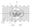
- FIG. 1 is a schematic enlarged plan view for explaining (Rule 1) regarding the center side clear region 2 of the spectacle lens 1 according to one aspect of the present invention. Note that FIG. 1 employs the structure of the functional area 3 employed in ⁇ Concrete Example 2> described later.
- One of the characteristics of one aspect of the present invention is that, in a plan view, the portion within the central clear region 2 is between d [mm] above and d [mm] below the horizontal line passing through the eye point EP.
- d is at least one value in the range of 1.00 or more and 2.00 or less, the maximum width in the horizontal direction of the rectangular portion in the range of The nose side is larger.
- d is a definition related to the line of sight, taking into account the radius of the pupil size PS.
- d [mm] is 2.00 [mm]
- the pupil radius is assumed to be 2.00 [mm]
- the pupil diameter is assumed to be 4.00 [mm].
- the movable distance of the line of sight is greater on the nose side in the horizontal direction than on the ear side in the horizontal direction from the eye point EP.
- the value of d may be at least one value in the range of 1.00 or more and 2.00 or less, and may be 2.00 as exemplified in the above paragraph, or 1.50 good too.
- the maximum horizontal width of the rectangular portion on the nose side from the eye point EP may be 3.60 mm or more (preferably 4.00 mm or more), and there is no upper limit. When defining the upper limit, it is sufficient to apply the upper limit of the size of the center side clear area 2, which will be described later.
- the distance from the eye point EP to the nose side should be larger than the distance from the eye point EP to the ear side, but the difference between the two distances may be a value in the range of 0.40 to 3.00 mm, for example.
- the difference between the two distances may be defined as a relative value.
- a relative value For example, when the maximum horizontal width of the rectangular portion on the ear side from the eye point EP is the denominator and the maximum width on the nose side from the eye point EP is the numerator, the values are greater than 1.00 and 2.00. 00 or less.
- the lower limit of this value may be 1.20, 1.40 and the upper limit of this value may be 1.80, 1.60.
- a circle may be adopted instead of a rectangle in (Regulation 1) (another aspect of Regulation 1).
- the r is set to 1.50 or more. Even if we adopt the rule that the maximum distance from the eye point EP to the center of the circle in the horizontal direction is greater on the nose side than on the ear side when at least one value in the range of 0.50 or less is set. good.
- a circle whose center lies on a horizontal line passing through the eye point EP and which can be arranged in the central clear area 2 closest to the ear in the horizontal direction, and a circle ⁇ in the central clear area 2 Assuming a circle ⁇ that can be placed closest to the nose side in the horizontal direction, the distance ⁇ ' between the center of the circle ⁇ and the eye point EP is greater than the distance ⁇ ' between the center of the circle ⁇ and the eye point EP. You may adopt the rule that .
- the value of r may be 2.00 or 1.50.
- Each of these circles is also referred to herein as a clear pupil circle, since the value of 2r assumes the diameter of the pupil.
- the maximum distance on the nose side from the eye point EP to the center of the circle in the horizontal direction shall be 1.60 mm or more (preferably 2.00 mm or more). good too. Also, the maximum distance in the horizontal direction from the eye point EP to the nose-side end of the circle may be 3.60 mm or more (preferably 4.00 mm or more). There is no upper limit for any of them. When defining the upper limit, it is sufficient to apply the upper limit of the size of the center side clear area 2, which will be described later.
- the difference between the maximum distance on the ear side and the maximum distance on the nose side from the eye point EP to the center of the circle in the horizontal direction is, for example, 1. Values in the range of 00 to 3.00 mm are possible.
- the difference between the two distances may be defined as a relative value.
- a relative value For example, when the maximum distance on the ear side from the eye point EP to the center of the circle in the horizontal direction is the denominator, and the maximum distance on the nose side is the numerator, the value is greater than 1.00 and less than or equal to 2.00. good.
- the lower limit of this value may be 1.20, 1.40 and the upper limit of this value may be 1.80, 1.60.
- Provision 1 may be adopted in combination with (Another aspect of Provision 1).
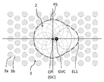
- FIG. 2 is a schematic enlarged plan view for explaining (Regulation 2) regarding the central clear region 2 of the spectacle lens 1 according to one aspect of the present invention. Note that FIG. 2 employs the structure of the functional area 3 employed in ⁇ Specific Example 2> described later.
- the center-side clear region 2 side of the functional region 3 has a shape that does not converge the luminous flux incident on the pupil of the wearer on the retina.
- Envelope curve (Fig. 2 symbol EL1) may be the shape of the central clear area 2 (that is, the boundary line between the central clear area 2 and the functional area 3).
- an envelope will be exemplified, but the shape of the center side clear area 2 may be a "collection of clear pupil circles” instead of an envelope of a collection of clear pupil circles. That is, the center-side clear area 2 may include the eyepoint EP and be configured by an aggregate of clear pupil circles.
- the center of gravity GVC of the shape of the center-side clear region 2 may be arranged on the nose side of the eye point EP.
- the above (Regulation 2) is also one aspect of specifying the shape of the center side clear area 2 .
- the center of gravity GVC of the shape of the central clear area 2 is arranged closer to the nose than the eye point EP, so that the line of sight can easily pass through the central clear area 2 when the eyes are converged. If the center of gravity GVC of the shape of the central clear area 2 is arranged on the nose side in the horizontal direction when viewed from the eye point EP, the line of sight can more reliably pass through the central clear area 2 when the eyes are converged.
- the horizontal distance from the eyepoint EP to the center of gravity GVC or the midpoint is, for example, 0.10 (or 1.00). ) to 3.00 mm.
- the shape on the ear side and the shape on the nose side are asymmetric with respect to the vertical line passing through the eye point EP.
- the shape of the center-side clear region 2 is half a shape A with rounded corners of a polygon (or a perfect circle or ellipse) on the ear side, while shape A on the nose side.
- the shape of the other half has a flared (in other words, expanded) shape from the center of gravity GVC of the body to the horizontal nasal side.
- Provision 3 One of the characteristics of one aspect of the present invention is that, in plan view, the central clear region 2 protrudes further toward the nose side than toward the ear side in the horizontal direction when viewed from the eye point EP.
- the wearer of the spectacle lens 1 for suppressing progression of myopia or hyperopia has near vision.
- the luminous flux entering the pupil of the wearer passes through the center-side clear area 2, converges on the retina, and good visibility is obtained.
- FIG. 1 Each figure of the present application illustrates a case where the lens for the right eye is viewed from above, but one aspect of the present invention can also be applied to the spectacle lens 1 for the left eye.
- a spectacle lens pair to which one aspect of the present invention is applied to each of them provides good visibility while obtaining a myopia progression suppressing function.
- the surface shape of the spectacle lens that is different from the central clear region in the entire annular functional region (for example, processed to partially scatter light, such as frosted glass) or the internal embedding structure does not necessarily have
- the convex region is provided in an island shape like the first refraction region of Patent Document 1
- the second refraction region (the base region that performs the same function as the center side clear region) that achieves the prescription power is provided.
- an annular region including the base region and the convex region may be regarded as the functional region.
- the rotation angle in the +Y direction as viewed from the eye point EP is zero degrees
- no convex region or the like is provided over a rotation angle range of several degrees to ten-odd degrees around 90 degrees clockwise (nose side in the horizontal direction).
- the size and shape of the central clear area 2 are not limited. As one guideline for the lower limit of the size of the center-side clear area 2, it should be a size that can encompass a circle with a diameter of 5.00 mm centered on the eye point EP. As one guideline for the upper limit of the size of the center side clear area 2, the size should be within a circle with a diameter of 10.00 mm centered on the eye point EP.
- the minimum value of the horizontal distance from the eyepoint EP to the edge of the center-side clear area 2 may be 3.60 mm or less.
- the area of the center side clear region 2 may be 80 mm 2 or less.
- the shape of the center side clear area 2 may be circular, rectangular, elliptical, or the like in plan view.
- the size and shape of the functional area 3 are not limited. As one guideline for the lower limit of the size of the functional region 3, it should be a size that can encompass a circle with a diameter of 15 mm centered on the eye point EP. As one guideline for the upper limit of the size of the functional region 3, a size that can encompass a circle with a diameter of 50.00 mm centered on the eye point EP is sufficient.
- the shape of the functional region 3 is annular in plan view, and the ring is formed inside (that is, the boundary between the central clear region 2 and the functional region 3) and/or outside (that is, between the outer clear region 4 and the functional region 3). boundary) may be circular, rectangular, elliptical, or a combination thereof.
- 30% or more (or 40% or more, 50% or more, or 60% or more) of the light flux incident on the pupil of the wearer may be defined as not converging on the retina. good. If the % value is large, the effect of suppressing progression of myopia or hyperopia is expected to be large, but the visibility is lowered. The value of the % may be appropriately determined in consideration of the effect of suppressing progression of myopia or hyperopia and visibility.
- the area of the structure (convex region 3a, embedded structure) that exhibits the effect of suppressing the progression of myopia or hyperopia in plan view is 30% or more (or 40% or more, 50% or more) of the entire functional region 3. % or more, 60% or more).
- the upper limit may be, for example, 70%.
- An outer clear area 4 may be provided to allow the In that case, the functional area 3 becomes an annular area existing between the outer clear area 4 and the central clear area 2 .
- the aspect of specifying the shape of the center side clear region 2 may be used.
- the outer clear region 4 does not include the eye point EP and is configured by an aggregate of clear pupil circles in plan view.
- the area other than the central clear area 2 and the outer clear area 4 may be defined as the functional area 3 .
- a specific aspect of specifying the shape of the outer clear area 4 is as follows. In a plan view, attention is paid to the portion located closest to the outer edge side of the spectacle lens 1 and having a shape that does not converge the luminous flux entering the pupil of the wearer in the functional region 3 on the retina.
- the part located closest to the outer edge of the spectacle lens 1 refers to each part that is radially farthest in each range of 0 to 360 degrees in the circumferential direction when viewed from the eye point EP.
- the shape of the area sandwiched between the outer edge may be the shape of the outer clear area 4 .
- the shape of the outer clear region 4 may be a "collection of clear pupil circles" instead of the envelope of the collection of clear pupil circles.
- the outer clear area 4 may be annular or may have a shape that constitutes only a part of the ring.
- part of the functional region 3 may be in contact with the outer edge of the spectacle lens 1 and the other part of the functional region 3 may be in contact with the outer clear region 4 .
- the spectacle lens 1 according to one aspect of the present invention may be the spectacle lens 1 after being framed in a frame, and a part of the functional region 3 in the spectacle lens 1 is in contact with the outer edge of the spectacle lens 1 to form a functor. Other parts of the national region 3 may be in contact with the outer clear region 4 .
- the entire outer edge side of the functional area 3 is the outer clear area 4, that is, the outer edge side of the functional area 3.
- there is no structure eg, defocus region, convex region 3a and/or concave region, embedded structure, etc.
- the mode of arrangement of the plurality of defocus areas is not particularly limited. For example, from the viewpoint of visibility from the outside of the defocus area, designability provided by the defocus area, refractive power adjustment by the defocus area, etc. can decide.
- substantially circular defocus regions are arranged in an island shape (that is, without adjoining each other) at equal intervals in the circumferential direction and the radial direction. spaced apart).
- each convex area 3a is independently arranged discretely so that the center thereof becomes the vertex of an equilateral triangle (the center of each defocus area is arranged at the vertex of the honeycomb structure: hexagonal arrangement).
- the distance between the defocus areas may be 1.0 to 2.0 mm.
- the number of defocus areas may be 100 to 100,000.
- a defocus area is an example of a configuration in the functional area 3 that has the effect of suppressing the progression of myopia or hyperopia.
- a defocus area is an area in which at least part of the area does not condense light at the condensing position of the base area 3b from the viewpoint of geometrical optics.
- the defocus area is a portion corresponding to the minute projections of Patent Document 1.
- the spectacle lens 1 according to one aspect of the present invention is a lens for suppressing progression of myopia, like the spectacle lens described in Patent Document 1.
- the plurality of defocus areas according to one aspect of the present invention may be formed on at least one of the object-side surface and the eyeball-side surface of the spectacle lens 1 .
- a case where a plurality of defocus areas are provided only on the object-side surface of the spectacle lens 1 is mainly exemplified.
- the case where the defocus area has a curved surface shape protruding toward the outside of the lens will be exemplified.
- half or more of the plurality of defocus areas are arranged with the same period in plan view.
- An example of a pattern having the same period is an equilateral triangle arrangement in plan view (the center of the defocus area is arranged at the vertex of an equilateral triangle; hexagonal arrangement is also possible).
- the direction of the period may be circumferential and/or radial. It is preferably 80% or higher, more preferably 90% or higher, even more preferably 95% or higher.
- preferred examples of "the number of half or more of all defocus areas in the functional area (or the number of 80% or more)" are 80% or more, 90% or more, and 95% or more in the same order as above. , repetitive descriptions are omitted.
- the defocus area may have a spherical shape, an aspherical shape, a toric surface shape, or a shape in which these are mixed (for example, the central part of each defocused area has a spherical shape, and the peripheral parts outside the central part have an aspherical shape).
- a boundary between the central portion and the peripheral portion may be provided in a portion of 1/3 to 2/3 of the radius of the defocus area (or convex area 3a) in plan view.
- it is preferable that at least the central portion of the defocus area (or convex area 3a) has a convex curved shape that protrudes toward the outside of the lens.
- it is preferable that half or more of the plurality of defocus areas (all defocus areas in the functional area) are arranged with the same period in a plan view, so the defocus areas are spherical. is preferred.
- Each defocus area is configured, for example, as follows.
- the diameter of the defocus area in plan view is preferably about 0.6 to 2.0 mm.
- Each surface area may be about 0.50 to 3.14 mm 2 .
- the convex region 3a has a radius of curvature of 50 to 250 mm, preferably about 86 mm.
- the ratio of the total area of the defocus area to the total area of the defocus area and the base area 3b may be 20 to 60%.
- the minimum value of the defocus power provided by the defocus area on the spectacle lens 1 is in the range of 0.50 to 4.50D, and the maximum Preferably the value is in the range 3.00-10.00D.
- the difference between the maximum and minimum values is preferably within the range of 1.00-5.00D.
- Defocus power refers to the difference between the refractive power of each defocus area and the refractive power of a portion other than each defocus area.
- the “defocus power” is the difference between the average minimum and maximum power at a given location in the defocus area minus the power at the base.
- the defocus area is the convex area 3a.
- Refractive power in the present specification is the average refractive power in the direction in which the refractive power is minimum and the refractive power in the direction in which the refractive power is maximum (perpendicular to the direction). Average refractive power point to
- the lens substrate is made of thermosetting resin material such as thiourethane, allyl, acryl, epithio.
- resin material constituting the lens base material other resin material that can obtain a desired refractive power may be selected.
- a lens base material made of inorganic glass may be used instead of a resin material.
- the hard coat film is formed using, for example, thermoplastic resin or UV curable resin.
- the hard coat film can be formed by a method of immersing the lens substrate in a hard coat liquid, spin coating, or the like. By coating with such a hard coat film, the durability of the spectacle lens 1 can be improved.
- the antireflection film is formed by depositing an antireflection agent such as ZrO 2 , MgF 2 , Al 2 O 3 or the like by vacuum deposition.
- an antireflection agent such as ZrO 2 , MgF 2 , Al 2 O 3 or the like by vacuum deposition.
- the visibility of an image seen through the spectacle lens 1 can be improved by coating with such an antireflection film.
- a plurality of defocus areas are formed on the object-side surface of the lens substrate. Therefore, when the surface is coated with a hard coat film and an antireflection film, a plurality of defocus regions are formed by the hard coat film and the antireflection film following the defocus regions on the lens substrate.
- a lens substrate is molded by a known molding method such as casting polymerization.
- a lens substrate having a defocus region on at least one surface can be obtained by molding by cast polymerization using a mold having a molding surface provided with a plurality of recesses.
- a hard coat film is formed on the surface of the lens substrate.
- the hard coat film can be formed by a method of immersing the lens substrate in a hard coat liquid, spin coating, or the like.
- an antireflection film is formed on the surface of the hard coat film.
- the antireflection film can be formed by depositing a raw material for the film by vacuum deposition.
- a spectacle lens 1 having a plurality of defocus regions protruding toward the object side on the object side surface is obtained by the manufacturing method of such procedures.
- the film thickness of the coating formed through the above steps may be in the range of, for example, 0.1 to 100 ⁇ m (preferably 0.5 to 5.0 ⁇ m, more preferably 1.0 to 3.0 ⁇ m).
- the film thickness of the coating is determined according to the functions required of the coating, and is not limited to the exemplified range.
- More than one layer of coating can be formed on the coating.
- coatings include various coatings such as antireflection coatings, water-repellent or hydrophilic antifouling coatings, and antifogging coatings.
- a known technique can be applied to the method of forming these coatings.
- the technical idea of the present invention is also reflected in spectacles in which the spectacle lens 1 is cut in the vicinity of the peripheral edge based on a predetermined frame shape and fitted into the frame.
- the type, shape, etc. of the frame There are no restrictions on the type, shape, etc. of the frame, and it may be full-rim, half-rim, under-rim, or rimless.
- FIG. 3 is a schematic plan view of spectacle lens 1 according to one aspect of the present invention before applying one aspect of the present invention to ⁇ Specific Example 1>.
- FIG. 4 is a schematic plan view after applying one aspect of the present invention to ⁇ Specific Example 1> of the spectacle lens 1 according to one aspect of the present invention.
- the spectacle lens 1 below was produced. Note that the spectacle lens 1 is composed of only the lens base material, and no other material is laminated on the lens base material.
- S spherical refractive power
- C astigmatic refractive power
- Refractive index of lens substrate 1.589 Since the above contents are common to each specific example, description thereof will be omitted.
- the range of the center side clear area 2 is a circular area with a radius of 3.50 mm from the eye point EP, and the range of the functional area 3 is the lens center. , within a circle with a radius of 20.00 mm (excluding the central clear area 2).
- An outer clear region 4 is provided on the outer edge side of the spectacle lens 1 with respect to the functional region 3 .
- the functional region 3 of this specific example is processed to make the entire functional region 3 opaque like frosted glass.
- the functional region 3 includes a structure (eg, a defocus region, a convex region 3a and/or a concave region, an embedded structure, etc.) intended to provide an effect of suppressing progression of myopia or hyperopia, and a base region 3b. It may be an annular region containing.
- the center side clear region 2 is expanded horizontally toward the nose side, and the shape of the center side clear region 2 is elongated into an ellipse.
- the center side clear region 2 was elongated 1.00 mm toward the nose.
- the center side clear region 2 protruded 1.00 mm toward the nose side from the ear side.
- the center side clear area 2 was a perfect circle with a radius of 3.50 mm (diameter 7.00 mm) before applying one aspect of the present invention, but after applying one aspect of the present invention, the center side clear area 2
- the clear area 2 was an ellipse with a vertical axis (short axis) of 7.00 mm and a horizontal axis (long axis) of 8.00 mm.
- the center of gravity GVC is on the horizontal line passing through the eye point EP, and the distance from the eye point EP to the center of gravity GVC in the horizontal direction. was 0.50 mm, and the horizontal distance to the midpoint of the horizontal line segment passing through the eyepoint EP was 0.50 mm.
- the maximum amount of inward shift (the distance that can be moved toward the nose side) in the central clear region 2 was increased from 1.50 mm to 2.00 mm.
- the center side clear area 2 can include not only the distance pupil position PS1 but also the near pupil position PS2.
- FIG. 5 is a schematic plan view of ⁇ Specific Example 2> of the spectacle lens 1 according to one aspect of the present invention before applying one aspect of the present invention.
- FIG. 6 is a schematic plan view after applying one aspect of the present invention to ⁇ Specific Example 2> of the spectacle lens 1 according to one aspect of the present invention.
- Configuration of the functional area 3 The convex areas 3a are discretely arranged as defocus areas.
- a base region 3b other than the convex region 3a a base region 3b other than the convex region 3a.
- ⁇ Shape of convex region 3a spherical
- ⁇ Refractive power of convex region 3a 3.50D
- ⁇ Formation surface of the convex regions 3a the surface on the object side
- arrangement of the convex regions 3a in a plan view Each convex region 3a is arranged independently and discretely so that the center of each convex region 3a becomes the vertex of an equilateral triangle (honeycomb structure) The center of each convex region 3a is arranged at the vertex) - Shape of convex region 3a in plan view: perfect circle (diameter 1.00 mm) ⁇ Pitch between each convex region 3a (distance between centers of convex regions 3a): 1.50 mm
- the range of the center side clear region 2 is a circular region with a radius of approximately 3.45 mm from the eye point EP
- the range of the functional region 3 is the lens It was set within a circle with a radius of 20.00 mm from the center (excluding the center side clear area 2).
- An outer clear region 4 is provided on the outer edge side of the spectacle lens 1 with respect to the functional region 3 .
- the center-side clear region 2 is an envelope of a collection of circumscribed circles with respect to the convex region 3a of the functional region 3 (For example, the envelope EL1 in FIG. 2) is obtained as a contour (the same applies to the following specific examples).
- the functional region 3 is the circle described in the above paragraph.
- a shape very close to an annular region can be obtained (the same applies to the following specific examples).
- the outer boundary line (the dashed envelope EL2) of the functional region 3 shown in the drawings relating to specific examples 2 and 3 is not circular, but is slightly circular in the portion where the convex region 3a does not exist.
- the envelope EL2 is shown as a circle as a schematic diagram in each figure.
- the center side clear region 2 was expanded horizontally to the nasal side. Specifically, one upper and lower convex region 3a closest to the horizontal line passing through the eyepoint EP and closest to the eyepoint EP (the geometric center GC of the spectacle lens 1) before applying one aspect of the present invention. was not provided. As a result, the shape of the center side clear area 2 is extended horizontally toward the nose side.
- the center of gravity GVC is on the horizontal line passing through the eye point EP, and the distance from the eye point EP to the center of gravity GVC in the horizontal direction. was about 0.4 mm, and the horizontal distance to the midpoint of the horizontal line segment passing through the eyepoint EP was 0.59 mm.
- the maximum amount of inward shift (distance that can be moved toward the nose side) in the center side clear area increased from 1.51 mm to 2.70 mm.
- the center side clear area 2 can include not only the distance pupil position PS1 but also the near pupil position PS2.
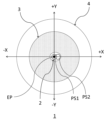
- FIG. 7 is a schematic plan view of ⁇ Specific Example 3> of the spectacle lens 1 according to one aspect of the present invention before applying one aspect of the present invention.
- FIG. 8 is a schematic plan view after applying one aspect of the present invention to ⁇ Specific Example 3> of the spectacle lens 1 according to one aspect of the present invention.
- the arrangement of the convex region 3a in plan view has been changed. Specifically, the convex regions 3a were aligned horizontally and vertically. The pitch between the convex regions 3a (the distance between the centers of the convex regions 3a) was 1.25 mm.
- the range of the center side clear area 2 is a circular area with a radius of 3.25 mm from the eye point EP, and the range of the functional area 3 is the lens center. , within a circle with a radius of 20.00 mm (excluding the central clear area 2).
- An outer clear region 4 is provided on the outer edge side of the spectacle lens 1 with respect to the functional region 3 .
- the center side clear region 2 was expanded horizontally to the nasal side. Specifically, before applying one aspect of the present invention, one above and below the horizontal line closest to the eyepoint EP (the geometric center GC of the spectacle lens 1) and the horizontal line pass through. In addition, one convex region 3a in the adjacent row (arranged in the Y direction) was not provided. As a result, the shape of the center side clear area 2 is extended horizontally toward the nose side.
- This specific example satisfies the above (Rule 1). Specifically, when d is set to 1.50 mm, the maximum width in the horizontal direction of the rectangular portion of (Regulation 1) is 1.5 mm on the nose side from the eye point EP than on the ear side from the eye point EP. 25 mm larger. This specific example also satisfies the above (another aspect of Regulation 1).
- the center of gravity GVC is on the horizontal line passing through the eye point EP, and the distance from the eye point EP to the center of gravity GVC in the horizontal direction. was about 0.4 mm, and the horizontal distance to the midpoint of the horizontal line segment passing through the eyepoint EP was 0.63 mm.
- the maximum amount of inward shift (distance that can be moved toward the nose side) in the center side clear area increased from 1.25 mm to 2.50 mm.
- the center side clear area 2 can include not only the distance pupil position PS1 but also the near pupil position PS2.
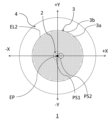
- FIG. 9 is a schematic plan view of ⁇ Specific Example 4> of the spectacle lens 1 according to one aspect of the present invention before applying one aspect of the present invention.
- FIG. 10 is a schematic plan view after applying one aspect of the present invention to ⁇ Specific Example 4> of the spectacle lens 1 according to one aspect of the present invention.
- the arrangement of the convex regions 3a in plan view has been changed. Specifically, the convex regions 3a were aligned in the circumferential direction. This alignment was done by diameter (by distance from eyepoint EP). Alignment status is shown in the table below. In the table below, the ring number is the number assigned to the circumferentially aligned group of convex regions 3a in order of proximity from the eye point EP, the radius is the radius of the ring, and the number of convex regions 3a and is the number of convex regions 3a arranged on the ring.
- the range of the center side clear area 2 is a circular area with a radius of 3.35 mm from the eye point EP, and the range of the functional area 3 is the lens center. , within a circle with a radius of 20.00 mm (excluding the central clear area 2).
- An outer clear region 4 is provided on the outer edge side of the spectacle lens 1 with respect to the functional region 3 .
- the center side clear region 2 was expanded horizontally to the nasal side.
- the horizontal line passing through the eyepoint EP is closest and closest to the eyepoint EP (the geometric center GC of the spectacle lens 1).
- a total of three convex regions 3a were not provided, one each on the upper and lower sides and one through which the horizontal line passes.
- the shape of the center side clear area 2 is extended horizontally toward the nose side.
- the center of gravity GVC is on the horizontal line passing through the eye point EP, and the distance from the eye point EP to the center of gravity GVC in the horizontal direction. was about 0.5 mm, and the horizontal distance to the midpoint of the horizontal line segment passing through the eyepoint EP was 0.72 mm.
- the maximum amount of inward shift (distance that can be moved toward the nose side) in the center side clear area increased from 1.34 mm to 2.47 mm.
- the center side clear area 2 can include not only the distance pupil position PS1 but also the near pupil position PS2.
- Reference Signs List 1 Spectacle lens 2 Central clear area 3 Functional area 3 a Convex area 3 b Base area 4 Outer clear area EP Eye point GC Geometric center GVC Center of gravity PS Pupil size PS1 Distance pupil position PS2 Near pupil position EL1 Envelope line EL2 (which forms the shape of the center-side clear area) Envelope (which forms the boundary between the outer clear region and the functional region)
Landscapes
- Physics & Mathematics (AREA)
- Health & Medical Sciences (AREA)
- Ophthalmology & Optometry (AREA)
- General Physics & Mathematics (AREA)
- Optics & Photonics (AREA)
- General Health & Medical Sciences (AREA)
- Eyeglasses (AREA)
Abstract
Description
アイポイントを含む領域であって、物体側の面から入射した光束を、眼球側の面から出射させ、装用者の瞳孔内に入射させ、網膜上に収束させる中心側クリア領域と、
前記中心側クリア領域を包囲する環状の領域であって、物体側の面から入射した光束を、眼球側の面から出射させる一方、装用者の瞳孔内に入射させた光束の少なくとも一部は網膜上に収束させないファンクショナル領域と、を備え、
平面視において、前記中心側クリア領域内の部分であって、アイポイントを通過する水平線から上方d[mm]と下方d[mm]との間の範囲の矩形状の部分の水平方向の最大幅は、dを1.00以上2.00以下の範囲の少なくともいずれか一つの値としたとき、アイポイントから耳側よりもアイポイントから鼻側の方が大きい、眼鏡レンズである。
dは1.50である、第1の態様に記載の眼鏡レンズである。
前記矩形状の部分において、アイポイントから水平方向鼻側の最大幅は3.60mm以上である、第1又は第2の態様に記載の眼鏡レンズである。
アイポイントを含む領域であって、物体側の面から入射した光束を、眼球側の面から出射させ、装用者の瞳孔内に入射させ、網膜上に収束させる中心側クリア領域と、
前記中心側クリア領域を包囲する環状の領域であって、物体側の面から入射した光束を、眼球側の面から出射させる一方、装用者の瞳孔内に入射させた光束の少なくとも一部は網膜上に収束させないファンクショナル領域と、を備え、
平面視において、前記ファンクショナル領域内での装用者の瞳孔内に入射させた光束を網膜上に収束させない形状の部分に対して前記中心側クリア領域側で他の該部分を含まずに外接可能な半径2.00mmの全ての円の集合体を前記中心側クリア領域の形状としたとき、前記中心側クリア領域において、アイポイントを通過する垂直線に対して耳側の形状と鼻側の形状とが非対称であり、且つ、アイポイントから水平方向鼻側の最大距離は3.60mm以上である、眼鏡レンズである。
前記中心側クリア領域の形状の重心、及び、前記中心側クリア領域の形状においてアイポイントを通過する水平線分の中点の少なくともいずれかが、アイポイントよりも鼻側に配置された、第4の態様に記載の眼鏡レンズである。
アイポイントを含む領域であって、物体側の面から入射した光束を、眼球側の面から出射させ、装用者の瞳孔内に入射させ、網膜上に収束させる中心側クリア領域と、
前記中心側クリア領域を包囲する環状の領域であって、物体側の面から入射した光束を、眼球側の面から出射させる一方、装用者の瞳孔内に入射させた光束の少なくとも一部は網膜上に収束させないファンクショナル領域と、を備え、
平面視において、前記中心側クリア領域は、アイポイントから見て水平方向の耳側よりも鼻側に張り出した、眼鏡レンズである。
眼鏡レンズの外縁側にて前記ファンクショナル領域と接する領域であって、物体側の面から入射した光束を、眼球側の面から出射させ、装用者の瞳孔内に入射させ、網膜上に収束させる外側クリア領域を備える、第1~第6のいずれか一つの態様に記載の眼鏡レンズである。
前記ファンクショナル領域では、前記装用者の瞳孔内に入射させた光束の30%以上は網膜上に収束させない、第1~第7のいずれか一つの態様に記載の眼鏡レンズである。
平面視において、前記中心側クリア領域は、アイポイントを中心とした直径10.00mmの円内に収まる大きさである、第1~第8のいずれか一つの態様に記載の眼鏡レンズである。
装用者に向かって右方を+X方向、左方を-X方向、上方を+Y方向、下方を-Y方向、物体側方向を+Z方向、その逆方向(奥側方向)を-Z方向とする。本明細書において、「平面視」とは+Z方向から-Z方向へと見たときの状態を指す。
本願各図では右眼用レンズを平面視した場合を例示しており、該右眼用レンズを装用した時の鼻側方向を+X方向、耳側方向を-X方向としている。
なお、眼球側の最表面のみにファンクショナル領域が設けられる場合は、-Z方向から+Z方向へと見たときの状態を平面視としても差し支えない。以降、眼鏡レンズにおけるアイポイント及び幾何中心等のような「位置」を論ずる際は、特記無い限り平面視での位置のことを指す。
本発明の一態様に係る眼鏡レンズは中心側クリア領域とファンクショナル領域とを備える。
図1は、本発明の一態様に係る眼鏡レンズ1の中心側クリア領域2に関する(規定1)を説明するための概略拡大平面図である。なお、図1では、後掲の<具体例2>で採用したファンクショナル領域3の構造を採用している。
図2は、本発明の一態様に係る眼鏡レンズ1の中心側クリア領域2に関する(規定2)を説明するための概略拡大平面図である。なお、図2では、後掲の<具体例2>で採用したファンクショナル領域3の構造を採用している。
本発明の一態様の特徴の一つは、平面視において、中心側クリア領域2は、アイポイントEPから見て水平方向の耳側よりも鼻側に張り出すことである。
本発明の一態様における眼鏡レンズ1の好適例及び変形例について、以下に述べる。
複数のデフォーカス領域の配置の態様は、特に限定されるものではなく、例えば、デフォーカス領域の外部からの視認性、デフォーカス領域によるデザイン性付与、デフォーカス領域による屈折力調整等の観点から決定できる。
そして、レンズ基材を得たら、次いで、そのレンズ基材の表面に、ハードコート膜を成膜する。ハードコート膜は、ハードコート液にレンズ基材を浸漬させる方法や、スピンコート等を使用することにより、形成することができる。
ハードコート膜を成膜したら、更に、そのハードコート膜の表面に、反射防止膜を成膜する。反射防止膜は、該膜のための原料を真空蒸着により成膜することにより、形成することができる。
このような手順の製造方法により、物体側に向けて突出する複数のデフォーカス領域を物体側の面に有する眼鏡レンズ1が得られる。
所定のフレーム形状に基づいて上記眼鏡レンズ1の周縁近傍をカットし、フレームに嵌め入れた眼鏡にも本発明の技術的思想が反映されている。フレームの種類、形状等には限定は無く、フルリム、ハーフリム、アンダーリム、リムレスであってもよい。
図3は、本発明の一態様に係る眼鏡レンズ1の<具体例1>において本発明の一態様を適用する前の概略平面図である。
図4は、本発明の一態様に係る眼鏡レンズ1の<具体例1>において本発明の一態様を適用した後の概略平面図である。
・レンズ基材の平面視での直径:60.00mm
・レンズ基材の種類:PC(ポリカーボネート)
・レンズ基材の屈折率:1.589
上記の内容は、各具体例に共通の内容であるため、以降は記載を省略する。
図5は、本発明の一態様に係る眼鏡レンズ1の<具体例2>において本発明の一態様を適用する前の概略平面図である。
図6は、本発明の一態様に係る眼鏡レンズ1の<具体例2>において本発明の一態様を適用した後の概略平面図である。
・ファンクショナル領域3の構成:デフォーカス領域として凸状領域3aを離散配置。
ファンクショナル領域3内において、凸状領域3a以外はベース領域3b。
・凸状領域3aの形状:球面
・凸状領域3aの屈折力:3.50D
・凸状領域3aの形成面:物体側の面
・凸状領域3aの平面視での配置:各凸状領域3aの中心が正三角形の頂点となるよう各々独立して離散配置(ハニカム構造の頂点に各凸状領域3aの中心が配置)
・凸状領域3aの平面視での形状:正円(直径1.00mm)
・各凸状領域3a間のピッチ(凸状領域3aの中心間の距離):1.50mm
・装用者の瞳孔径:4.00mmと想定
図7は、本発明の一態様に係る眼鏡レンズ1の<具体例3>において本発明の一態様を適用する前の概略平面図である。
図8は、本発明の一態様に係る眼鏡レンズ1の<具体例3>において本発明の一態様を適用した後の概略平面図である。
図9は、本発明の一態様に係る眼鏡レンズ1の<具体例4>において本発明の一態様を適用する前の概略平面図である。
図10は、本発明の一態様に係る眼鏡レンズ1の<具体例4>において本発明の一態様を適用した後の概略平面図である。

2・・・中心側クリア領域
3・・・ファンクショナル領域
3a・・・凸状領域
3b・・・ベース領域
4・・・外側クリア領域
EP・・・アイポイント
GC・・・幾何中心
GVC・・・重心
PS・・・瞳孔サイズ
PS1・・・遠用瞳孔位置
PS2・・・近用瞳孔位置
EL1・・・(中心側クリア領域の形状となる)包絡線
EL2・・・(外側クリア領域とファンクショナル領域との境界の形状となる)包絡線
Claims (9)
- アイポイントを含む領域であって、物体側の面から入射した光束を、眼球側の面から出射させ、装用者の瞳孔内に入射させ、網膜上に収束させる中心側クリア領域と、
前記中心側クリア領域を包囲する環状の領域であって、物体側の面から入射した光束を、眼球側の面から出射させる一方、装用者の瞳孔内に入射させた光束の少なくとも一部は網膜上に収束させないファンクショナル領域と、を備え、
平面視において、前記中心側クリア領域内の部分であって、アイポイントを通過する水平線から上方d[mm]と下方d[mm]との間の範囲の矩形状の部分の水平方向の最大幅は、dを1.00以上2.00以下の範囲の少なくともいずれか一つの値としたとき、アイポイントから耳側よりもアイポイントから鼻側の方が大きい、眼鏡レンズ。 - dは1.50である、請求項1に記載の眼鏡レンズ。
- 前記矩形状の部分において、アイポイントから水平方向鼻側の最大幅は3.60mm以上である、請求項1又は2に記載の眼鏡レンズ。
- アイポイントを含む領域であって、物体側の面から入射した光束を、眼球側の面から出射させ、装用者の瞳孔内に入射させ、網膜上に収束させる中心側クリア領域と、
前記中心側クリア領域を包囲する環状の領域であって、物体側の面から入射した光束を、眼球側の面から出射させる一方、装用者の瞳孔内に入射させた光束の少なくとも一部は網膜上に収束させないファンクショナル領域と、を備え、
平面視において、前記ファンクショナル領域内での装用者の瞳孔内に入射させた光束を網膜上に収束させない形状の部分に対して前記中心側クリア領域側で他の該部分を含まずに外接可能な半径2.00mmの全ての円の集合体を前記中心側クリア領域の形状としたとき、前記中心側クリア領域において、アイポイントを通過する垂直線に対して耳側の形状と鼻側の形状とが非対称であり、且つ、アイポイントから水平方向鼻側の最大距離は3.60mm以上である、眼鏡レンズ。 - 前記中心側クリア領域の形状の重心、及び、前記中心側クリア領域の形状においてアイポイントを通過する水平線分の中点の少なくともいずれかが、アイポイントよりも鼻側に配置された、請求項4に記載の眼鏡レンズ。
- アイポイントを含む領域であって、物体側の面から入射した光束を、眼球側の面から出射させ、装用者の瞳孔内に入射させ、網膜上に収束させる中心側クリア領域と、
前記中心側クリア領域を包囲する環状の領域であって、物体側の面から入射した光束を、眼球側の面から出射させる一方、装用者の瞳孔内に入射させた光束の少なくとも一部は網膜上に収束させないファンクショナル領域と、を備え、
平面視において、前記中心側クリア領域は、アイポイントから見て水平方向の耳側よりも鼻側に張り出した、眼鏡レンズ。 - 眼鏡レンズの外縁側にて前記ファンクショナル領域と接する領域であって、物体側の面から入射した光束を、眼球側の面から出射させ、装用者の瞳孔内に入射させ、網膜上に収束させる外側クリア領域を備える、請求項1~6のいずれか一つ記載の眼鏡レンズ。
- 前記ファンクショナル領域では、前記装用者の瞳孔内に入射させた光束の30%以上は網膜上に収束させない、請求項1~7のいずれか一つに記載の眼鏡レンズ。
- 平面視において、前記中心側クリア領域は、アイポイントを中心とした直径10.00mmの円内に収まる大きさである、請求項1~8のいずれか一つに記載の眼鏡レンズ。
Priority Applications (4)
| Application Number | Priority Date | Filing Date | Title |
|---|---|---|---|
| US18/294,081 US20240337865A1 (en) | 2021-09-15 | 2022-08-05 | Spectacle lens |
| EP22869720.7A EP4403983A1 (en) | 2021-09-15 | 2022-08-05 | Spectacle lens |
| CN202280060224.4A CN117916651A (zh) | 2021-09-15 | 2022-08-05 | 眼镜镜片 |
| KR1020247001613A KR20240021301A (ko) | 2021-09-15 | 2022-08-05 | 안경 렌즈 |
Applications Claiming Priority (2)
| Application Number | Priority Date | Filing Date | Title |
|---|---|---|---|
| JP2021-150384 | 2021-09-15 | ||
| JP2021150384A JP2023042948A (ja) | 2021-09-15 | 2021-09-15 | 眼鏡レンズ |
Publications (1)
| Publication Number | Publication Date |
|---|---|
| WO2023042572A1 true WO2023042572A1 (ja) | 2023-03-23 |
Family
ID=85602750
Family Applications (1)
| Application Number | Title | Priority Date | Filing Date |
|---|---|---|---|
| PCT/JP2022/030171 WO2023042572A1 (ja) | 2021-09-15 | 2022-08-05 | 眼鏡レンズ |
Country Status (6)
| Country | Link |
|---|---|
| US (1) | US20240337865A1 (ja) |
| EP (1) | EP4403983A1 (ja) |
| JP (1) | JP2023042948A (ja) |
| KR (1) | KR20240021301A (ja) |
| CN (1) | CN117916651A (ja) |
| WO (1) | WO2023042572A1 (ja) |
Citations (7)
| Publication number | Priority date | Publication date | Assignee | Title |
|---|---|---|---|---|
| JP2011501222A (ja) * | 2007-10-23 | 2011-01-06 | ビジョン シーアールシー リミテッド | 眼用レンズ素子 |
| JP2013533044A (ja) * | 2010-07-26 | 2013-08-22 | ヴィジョン・シーアールシー・リミテッド | 眼の屈折異常の治療 |
| US20170131567A1 (en) | 2015-11-06 | 2017-05-11 | Hoya Lens Thailand Ltd. | Spectacle Lens |
| WO2019166657A1 (en) | 2018-03-01 | 2019-09-06 | Essilor International | Lens element |
| WO2020014613A1 (en) * | 2018-07-12 | 2020-01-16 | Sightglass Vision, Inc. | Methods and devices for reducing myopia in children |
| WO2020045567A1 (ja) | 2018-08-31 | 2020-03-05 | ホヤ レンズ タイランド リミテッド | 眼鏡レンズ、眼鏡レンズの製造方法および眼鏡レンズ用被膜 |
| US10884264B2 (en) | 2018-01-30 | 2021-01-05 | Sightglass Vision, Inc. | Ophthalmic lenses with light scattering for treating myopia |
Family Cites Families (1)
| Publication number | Priority date | Publication date | Assignee | Title |
|---|---|---|---|---|
| EP4009048A1 (en) | 2015-03-27 | 2022-06-08 | Agilent Technologies, Inc. | Method and system for determining integrated metabolic baseline and potential of living cells |
-
2021
- 2021-09-15 JP JP2021150384A patent/JP2023042948A/ja active Pending
-
2022
- 2022-08-05 WO PCT/JP2022/030171 patent/WO2023042572A1/ja active Application Filing
- 2022-08-05 EP EP22869720.7A patent/EP4403983A1/en active Pending
- 2022-08-05 KR KR1020247001613A patent/KR20240021301A/ko unknown
- 2022-08-05 US US18/294,081 patent/US20240337865A1/en active Pending
- 2022-08-05 CN CN202280060224.4A patent/CN117916651A/zh active Pending
Patent Citations (7)
| Publication number | Priority date | Publication date | Assignee | Title |
|---|---|---|---|---|
| JP2011501222A (ja) * | 2007-10-23 | 2011-01-06 | ビジョン シーアールシー リミテッド | 眼用レンズ素子 |
| JP2013533044A (ja) * | 2010-07-26 | 2013-08-22 | ヴィジョン・シーアールシー・リミテッド | 眼の屈折異常の治療 |
| US20170131567A1 (en) | 2015-11-06 | 2017-05-11 | Hoya Lens Thailand Ltd. | Spectacle Lens |
| US10884264B2 (en) | 2018-01-30 | 2021-01-05 | Sightglass Vision, Inc. | Ophthalmic lenses with light scattering for treating myopia |
| WO2019166657A1 (en) | 2018-03-01 | 2019-09-06 | Essilor International | Lens element |
| WO2020014613A1 (en) * | 2018-07-12 | 2020-01-16 | Sightglass Vision, Inc. | Methods and devices for reducing myopia in children |
| WO2020045567A1 (ja) | 2018-08-31 | 2020-03-05 | ホヤ レンズ タイランド リミテッド | 眼鏡レンズ、眼鏡レンズの製造方法および眼鏡レンズ用被膜 |
Also Published As
| Publication number | Publication date |
|---|---|
| EP4403983A1 (en) | 2024-07-24 |
| JP2023042948A (ja) | 2023-03-28 |
| KR20240021301A (ko) | 2024-02-16 |
| US20240337865A1 (en) | 2024-10-10 |
| CN117916651A (zh) | 2024-04-19 |
Similar Documents
| Publication | Publication Date | Title |
|---|---|---|
| CN113366377B (zh) | 眼镜镜片及其设计方法 | |
| US20230229018A1 (en) | Eyeglass lens | |
| WO2021186878A1 (ja) | 眼鏡レンズ | |
| WO2021181885A1 (ja) | 眼鏡レンズ | |
| CN217718323U (zh) | 一种眼镜片及眼镜 | |
| WO2023042572A1 (ja) | 眼鏡レンズ | |
| JP7177959B1 (ja) | 眼鏡レンズ | |
| JP7217676B2 (ja) | 眼鏡レンズおよびその設計方法 | |
| WO2022190610A1 (ja) | 眼鏡レンズ及びその設計方法 | |
| WO2023166822A1 (ja) | 眼鏡レンズ、眼鏡レンズの製造方法、眼鏡レンズの設計方法、眼鏡及び眼鏡の製造方法 | |
| WO2024019071A1 (ja) | 眼鏡レンズの設計方法、眼鏡レンズの製造方法、眼鏡レンズ及び眼鏡 | |
| WO2024019070A1 (ja) | 眼鏡レンズの設計方法、眼鏡レンズの製造方法、眼鏡レンズ及び眼鏡 | |
| WO2023171061A1 (ja) | 眼鏡レンズ、および眼鏡レンズの設計方法 | |
| CN218068482U (zh) | 一种散光离焦眼镜片及眼镜 | |
| AU2023241697A1 (en) | Spectacle lens and design method of spectacle lens |
Legal Events
| Date | Code | Title | Description |
|---|---|---|---|
| 121 | Ep: the epo has been informed by wipo that ep was designated in this application |
Ref document number: 22869720 Country of ref document: EP Kind code of ref document: A1 |
|
| ENP | Entry into the national phase |
Ref document number: 20247001613 Country of ref document: KR Kind code of ref document: A |
|
| WWE | Wipo information: entry into national phase |
Ref document number: 1020247001613 Country of ref document: KR |
|
| WWE | Wipo information: entry into national phase |
Ref document number: 2401000966 Country of ref document: TH |
|
| WWE | Wipo information: entry into national phase |
Ref document number: 11202400049U Country of ref document: SG |
|
| WWE | Wipo information: entry into national phase |
Ref document number: 202280060224.4 Country of ref document: CN |
|
| WWE | Wipo information: entry into national phase |
Ref document number: 2022869720 Country of ref document: EP |
|
| NENP | Non-entry into the national phase |
Ref country code: DE |
|
| ENP | Entry into the national phase |
Ref document number: 2022869720 Country of ref document: EP Effective date: 20240415 |