WO2023042569A1 - 蓄電モジュール用圧力調整弁及び蓄電ユニット - Google Patents
蓄電モジュール用圧力調整弁及び蓄電ユニット Download PDFInfo
- Publication number
- WO2023042569A1 WO2023042569A1 PCT/JP2022/029893 JP2022029893W WO2023042569A1 WO 2023042569 A1 WO2023042569 A1 WO 2023042569A1 JP 2022029893 W JP2022029893 W JP 2022029893W WO 2023042569 A1 WO2023042569 A1 WO 2023042569A1
- Authority
- WO
- WIPO (PCT)
- Prior art keywords
- power storage
- pressure regulating
- regulating valve
- storage module
- case
- Prior art date
- Legal status (The legal status is an assumption and is not a legal conclusion. Google has not performed a legal analysis and makes no representation as to the accuracy of the status listed.)
- Ceased
Links
Images
Classifications
-
- H—ELECTRICITY
- H01—ELECTRIC ELEMENTS
- H01M—PROCESSES OR MEANS, e.g. BATTERIES, FOR THE DIRECT CONVERSION OF CHEMICAL ENERGY INTO ELECTRICAL ENERGY
- H01M50/00—Constructional details or processes of manufacture of the non-active parts of electrochemical cells other than fuel cells, e.g. hybrid cells
- H01M50/30—Arrangements for facilitating escape of gases
- H01M50/308—Detachable arrangements, e.g. detachable vent plugs or plug systems
-
- H—ELECTRICITY
- H01—ELECTRIC ELEMENTS
- H01M—PROCESSES OR MEANS, e.g. BATTERIES, FOR THE DIRECT CONVERSION OF CHEMICAL ENERGY INTO ELECTRICAL ENERGY
- H01M50/00—Constructional details or processes of manufacture of the non-active parts of electrochemical cells other than fuel cells, e.g. hybrid cells
- H01M50/20—Mountings; Secondary casings or frames; Racks, modules or packs; Suspension devices; Shock absorbers; Transport or carrying devices; Holders
- H01M50/204—Racks, modules or packs for multiple batteries or multiple cells
- H01M50/207—Racks, modules or packs for multiple batteries or multiple cells characterised by their shape
- H01M50/209—Racks, modules or packs for multiple batteries or multiple cells characterised by their shape adapted for prismatic or rectangular cells
-
- H—ELECTRICITY
- H01—ELECTRIC ELEMENTS
- H01M—PROCESSES OR MEANS, e.g. BATTERIES, FOR THE DIRECT CONVERSION OF CHEMICAL ENERGY INTO ELECTRICAL ENERGY
- H01M50/00—Constructional details or processes of manufacture of the non-active parts of electrochemical cells other than fuel cells, e.g. hybrid cells
- H01M50/30—Arrangements for facilitating escape of gases
- H01M50/317—Re-sealable arrangements
-
- H—ELECTRICITY
- H01—ELECTRIC ELEMENTS
- H01M—PROCESSES OR MEANS, e.g. BATTERIES, FOR THE DIRECT CONVERSION OF CHEMICAL ENERGY INTO ELECTRICAL ENERGY
- H01M50/00—Constructional details or processes of manufacture of the non-active parts of electrochemical cells other than fuel cells, e.g. hybrid cells
- H01M50/30—Arrangements for facilitating escape of gases
- H01M50/317—Re-sealable arrangements
- H01M50/325—Re-sealable arrangements comprising deformable valve members, e.g. elastic or flexible valve members
-
- H—ELECTRICITY
- H01—ELECTRIC ELEMENTS
- H01M—PROCESSES OR MEANS, e.g. BATTERIES, FOR THE DIRECT CONVERSION OF CHEMICAL ENERGY INTO ELECTRICAL ENERGY
- H01M50/00—Constructional details or processes of manufacture of the non-active parts of electrochemical cells other than fuel cells, e.g. hybrid cells
- H01M50/30—Arrangements for facilitating escape of gases
- H01M50/35—Gas exhaust passages comprising elongated, tortuous or labyrinth-shaped exhaust passages
- H01M50/358—External gas exhaust passages located on the battery cover or case
-
- H—ELECTRICITY
- H01—ELECTRIC ELEMENTS
- H01M—PROCESSES OR MEANS, e.g. BATTERIES, FOR THE DIRECT CONVERSION OF CHEMICAL ENERGY INTO ELECTRICAL ENERGY
- H01M2200/00—Safety devices for primary or secondary batteries
- H01M2200/20—Pressure-sensitive devices
-
- H—ELECTRICITY
- H01—ELECTRIC ELEMENTS
- H01M—PROCESSES OR MEANS, e.g. BATTERIES, FOR THE DIRECT CONVERSION OF CHEMICAL ENERGY INTO ELECTRICAL ENERGY
- H01M2220/00—Batteries for particular applications
- H01M2220/20—Batteries in motive systems, e.g. vehicle, ship, plane
-
- Y—GENERAL TAGGING OF NEW TECHNOLOGICAL DEVELOPMENTS; GENERAL TAGGING OF CROSS-SECTIONAL TECHNOLOGIES SPANNING OVER SEVERAL SECTIONS OF THE IPC; TECHNICAL SUBJECTS COVERED BY FORMER USPC CROSS-REFERENCE ART COLLECTIONS [XRACs] AND DIGESTS
- Y02—TECHNOLOGIES OR APPLICATIONS FOR MITIGATION OR ADAPTATION AGAINST CLIMATE CHANGE
- Y02E—REDUCTION OF GREENHOUSE GAS [GHG] EMISSIONS, RELATED TO ENERGY GENERATION, TRANSMISSION OR DISTRIBUTION
- Y02E60/00—Enabling technologies; Technologies with a potential or indirect contribution to GHG emissions mitigation
- Y02E60/10—Energy storage using batteries
Definitions
- the present invention relates to a pressure regulating valve for an electricity storage module and an electricity storage unit.
- the pressure regulating valve includes a base member, a case member having a tubular portion, a valve body that is an elastic member accommodated in the tubular portion, and an opening of the case member. and a cover member that closes the The pressure regulating valve is fixed by welding the base member to the frame of the power storage module and welding the case member to the base member.
- the present invention has been made in view of the above problems, and an object thereof is to provide an electricity storage module pressure regulating valve and an electricity storage unit including the electricity storage module pressure regulating valve that can improve maintenance. It is in.
- the present invention provides an electricity storage module pressure regulating valve in which a case containing a valve body in a valve chamber is attached to an electricity storage device, wherein the case has a sealing surface provided with a sealing member and in contact with the power storage device, and an attachment portion that can be attached to the power storage device by moving along a predetermined sliding direction along the sealing surface.
- the case has a pair of edges extending in the sliding direction, and the mounting portion protrudes outward from the edges to extend the power storage module. It is a locked portion that is locked by the device.
- An electricity storage unit is an electricity storage unit including the electricity storage module pressure regulating valve and an electricity storage device, wherein the electricity storage device has a holding portion that holds the attachment portion.
- the holding section has a plurality of pairs of holding sections that sandwich the case along the sealing surface and in a direction orthogonal to the sliding direction.
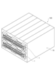
- FIG. 1 is a perspective view of an electricity storage unit provided with an electricity storage module pressure regulating valve according to an embodiment of the present invention
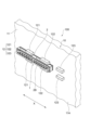
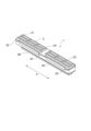
- 1 is a perspective view of a power storage module pressure regulating valve according to an embodiment of the present invention
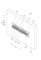
- FIG. 1 is a perspective view of a power storage module pressure regulating valve according to an embodiment of the present invention
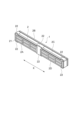
- FIG. 1 is a perspective view of a power storage module pressure regulating valve according to an embodiment of the present invention
- FIG. 1 is a perspective view of a power storage module pressure regulating valve according to an embodiment of the present invention
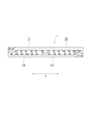
- FIG. 1 is a plan view of a power storage module pressure regulating valve according to an embodiment of the present invention
- FIG. 1 is a plan view of a power storage module pressure regulating valve according to an embodiment of the present invention
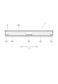
- FIG. 1 is a side view of a power storage module pressure regulating valve according to an embodiment of the present invention
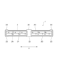
- FIG. 2 is a bottom view of the power storage module pressure regulating valve according to the embodiment of the present invention
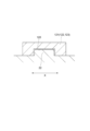
- 1 is a sectional view showing a main part of a power storage module pressure regulating valve according to an embodiment of the present invention
- FIG. 1 is a perspective view of an electricity storage unit 100 including an electricity storage module pressure regulating valve 1 according to an embodiment of the present invention
- FIG. 2 is a perspective view of the electricity storage module pressure regulating valve 1
- FIG. 4 is a perspective view of the power storage module pressure regulating valve 1
- FIG. 5 is a perspective view of the power storage module pressure regulating valve 1
- FIG. 6 is a plan view of the power storage module pressure regulating valve 1
- FIG. 7 is a side view of the power storage module pressure regulating valve
- FIG. 8 is a bottom view of the power storage module pressure regulating valve 1.
- FIG. 9 is a cross-sectional view showing a main part of the power storage module pressure regulating valve 1. As shown in FIG.
- a power storage module pressure regulating valve 1 is a power storage module pressure regulating valve in which a case 2 housing a valve body in a valve chamber is attached to a power storage device 10.
- the case 2 has a sealing surface 2A provided with a sealing member 21 and in contact with the power storage device 10, and moves along a predetermined sliding direction (X direction) along the sealing surface 2A to move the power storage device 10. and an attachment portion 22 that can be attached to the .
- the power storage unit 100 also includes the power storage module pressure regulating valve 1 and a power storage device (power storage module) 10 .
- the power storage module pressure regulating valve 1 and the power storage unit 100 will be specifically described below.
- the power storage module pressure regulating valve 1 is configured to release pressure when the internal pressure in the power storage device 10 rises.
- the power storage device 10 is, for example, a nickel-metal hydride battery, and is provided to supply electric power to a motor in a vehicle such as an electric vehicle or a hybrid vehicle.
- the case 2 is made of, for example, synthetic resin and is formed in a rectangular parallelepiped shape as a whole, and has a sealing surface 2A facing the power storage device 10 side and an open surface 2B facing the opposite side.
- a plurality of recesses are formed in the case 2 when viewed from the open surface 2B, and these recesses form valve chambers in which a valve body, which is an elastic member, is accommodated.
- a through hole is formed in the bottom of each recess so that gas can be introduced into the recess from the sealing surface 2A side.
- a cover member is provided on the side of the open surface 2B of the case 2 to close the recess. At this time, it is preferable that the cover member is detachable from the case 2 . Further, the cover member may be provided with a pressing portion that presses the valve body toward the valve closing side.
- the sealing surface 2A of the case 2 is formed in a frame shape as shown in FIGS.
- An area within each frame corresponds to an opening on the power storage device 10 side, and an appropriate number of recesses are formed in each area within the frame.
- a sealing member 21, which is an elastic member, is provided along the frame on the sealing surface 2A.
- the sealing member 21 may be an elastic member such as rubber or resin, and may be provided on the case 2 by integral molding, for example.
- the extending direction (the direction of the longest side) of the rectangular parallelepiped case 2 is defined as the X direction.
- the X direction is the slide direction.
- the case 2 is sandwiched between a sealing surface 2A and an opening surface 2B and has a pair of side surfaces 2C and 2D along the X direction. That is, the side surfaces 2C and 2D form a pair of edges along the sliding direction.
- Three mounting portions 22 are formed on each of the side surfaces 2C and 2D on the side of the sealing surface 2A.
- the mounting portion 22 is formed in a plate shape protruding outward from the side surfaces 2C and 2D.
- protruding outward means that the mounting portion 22 formed on the side surface 2C and the mounting portion 22 formed on the side surface 2D extend away from each other.
- the mounting portion 22 arranged in the central portion in the X direction has a larger dimension in the X direction than the other mounting portions 22 .
- the mounting portion 22 at the central portion can be engaged only with the central holding portion 122 among the holding portions 121 to 123, which will be described later. It should be noted that the dimensions of all mounting portions may be different from each other, or the dimensions of the central mounting portion may be smaller than the others.
- the power storage device 10 includes a housing 11 that houses a module having a power storage function.
- the housing 11 is formed with an opening for releasing gas when the internal pressure rises, and the power storage module pressure regulating valve 1 is provided so as to correspond to the opening. That is, when the internal pressure of power storage device 10 increases, gas is released from the opening of housing 11, and this gas passes through the through hole of case 2 and is introduced into the recess. When the pressure in the recess reaches or exceeds a preset value, the valve body opens the through hole and the gas is released to the external space.
- a housing 11 of the electricity storage device 10 is provided with a holding portion 12 for attaching the case 2 of the electricity storage module pressure regulating valve 1 by holding the attachment portion 22 .
- the holding portion 12 is formed so as to protrude from a mounting surface 11A of the housing 11 having an opening.
- the holding portion 12 is composed of three pairs of holding portions 121 to 123 corresponding to the mounting portion 22 of the case 2 . Incidentally, the numbers of the mounting portions 22 and the clamping portions 121 to 123 are not limited to the above.
- the mounting surface 11A is a surface with which the sealing surface 2A of the case 2 contacts.
- the holding portions 121 to 123 are arranged along the mounting surface 11A (along the sealing surface 2A) and sandwich the case 2 in a direction perpendicular to the X direction.
- the sealing surface 2A of the case 2 is brought into contact with the mounting surface 11A of the housing 11, and the case 2 is sandwiched between the sandwiching portions 121 and 122.
- the case 2 is slid along the X direction with respect to the housing 11 as shown in FIG.
- each mounting portion 22 is moved to a position corresponding to the clamping portions 121 to 123 and locked.
- the sealing member 21 is compressed so that it comes into close contact with the mounting surface 11A.
- the holding parts 121 to 123 have recesses 120.
- the mounting portion 22 climbs over the wall adjacent to the recess 120 in the X direction and is engaged with the recess 120 .
- the mounting portion 22 functions as a locked portion.
- the locking structure between the holding portion 12 and the mounting portion 22 is not limited to the structure described above, and may be any structure as long as it is locked by sliding movement in the X direction. Also, a tapered portion or the like may be formed in the mounting portion so that the wall portion can be easily climbed over during locking.
- the opening of the housing 11 corresponds to the area within the frame of the sealing surface 2A, and gas is introduced from the housing 11 into the recess.
- the introduction becomes possible, and the power storage module pressure regulating valve 1 can function.
- the use of the power storage unit 100 may cause the power storage module pressure regulating valve 1 to repeatedly open and close, or the valve body to deteriorate over time, making it impossible to obtain the desired valve opening characteristics.
- the case 2 is slid along the X direction with respect to the housing 11 from the state in which the mounting portion 22 is locked by the holding portion 12 as shown in FIG. be in a released state.
- the power storage module pressure regulating valve 1 can be removed from the power storage device 10, and appropriate maintenance work such as parts replacement and inspection can be performed.
- the entire power storage module pressure regulating valve 1 can be replaced.
- the moving direction when attaching and the moving direction when releasing the attachment are determined (by moving to one side in the X direction, the case 2 is locked, The locking may be released by moving to the other side), or it may be possible to attach and detach by moving in either direction.
- the case 2 has the mounting portion 22, so that the power storage module pressure regulating valve 1 and the power storage device 10 are mounted along the sliding direction. can be attached and detached by relatively displacing the , and the maintainability can be improved.
- the mounting portion 22 protrudes from the side surfaces 2C and 2D of the case 2, the mounting portion 22 can be easily locked by the power storage device 10.
- the holding portion 12 is composed of a plurality of pairs of holding portions 121 to 123 that hold the case 2 therebetween, the case 2 can be guided along the X direction, and attachment/detachment workability can be improved.
- the case 2 can be slid after the case 2 is arranged so that the mounting portion 22 is positioned between the two pairs of holding portions arranged in the X direction, and the holding portion is composed only of the pair of holding portions. As compared with the case where it is attached, it is possible to reduce the sliding amount at the time of attachment and detachment and improve workability.
- the present invention is not limited to the above embodiments, but includes other configurations and the like that can achieve the object of the present invention, and the following modifications and the like are also included in the present invention.
- the mounting portion 22 protrudes from the side surfaces 2C and 2D of the case 2.
- the mounting portion is formed in a projection-like shape projecting from the sealing surface and receives the projection.
- a recess or a through hole may be formed in the mounting surface of the power storage device.
- the holding portion 12 is configured by the plurality of holding portions 121 to 123 that hold the case 2 therebetween. good too.
- the present invention is not limited to the power storage module pressure regulating valves according to the above-described embodiments of the present invention, and is included in the concept and scope of the claims of the present invention. Including all aspects. Moreover, each configuration may be selectively combined as appropriate so as to achieve at least part of the above-described problems and effects. For example, the shape, material, arrangement, size, etc. of each component in the above embodiment may be appropriately changed according to the specific usage of the present invention.
Landscapes
- Chemical & Material Sciences (AREA)
- Chemical Kinetics & Catalysis (AREA)
- Electrochemistry (AREA)
- General Chemical & Material Sciences (AREA)
- Gas Exhaust Devices For Batteries (AREA)
- Battery Mounting, Suspending (AREA)
Priority Applications (5)
| Application Number | Priority Date | Filing Date | Title |
|---|---|---|---|
| CN202280062731.1A CN117941147A (zh) | 2021-09-16 | 2022-08-04 | 蓄电模块用压力调节阀及蓄电单元 |
| EP22869717.3A EP4404358A4 (en) | 2021-09-16 | 2022-08-04 | PRESSURE REGULATING VALVE FOR ENERGY STORAGE MODULE AND ENERGY STORAGE UNIT |
| US18/689,701 US20250132448A1 (en) | 2021-09-16 | 2022-08-04 | Pressure-regulating valve for power storage module and power storage unit |
| JP2023548159A JP7503717B2 (ja) | 2021-09-16 | 2022-08-04 | 蓄電モジュール用圧力調整弁及び蓄電ユニット |
| KR1020247007642A KR102887644B1 (ko) | 2021-09-16 | 2022-08-04 | 축전 모듈용 압력조정 밸브 및 축전 유닛 |
Applications Claiming Priority (2)
| Application Number | Priority Date | Filing Date | Title |
|---|---|---|---|
| JP2021151486 | 2021-09-16 | ||
| JP2021-151486 | 2021-09-16 |
Publications (1)
| Publication Number | Publication Date |
|---|---|
| WO2023042569A1 true WO2023042569A1 (ja) | 2023-03-23 |
Family
ID=85602737
Family Applications (1)
| Application Number | Title | Priority Date | Filing Date |
|---|---|---|---|
| PCT/JP2022/029893 Ceased WO2023042569A1 (ja) | 2021-09-16 | 2022-08-04 | 蓄電モジュール用圧力調整弁及び蓄電ユニット |
Country Status (6)
| Country | Link |
|---|---|
| US (1) | US20250132448A1 (cg-RX-API-DMAC7.html) |
| EP (1) | EP4404358A4 (cg-RX-API-DMAC7.html) |
| JP (1) | JP7503717B2 (cg-RX-API-DMAC7.html) |
| KR (1) | KR102887644B1 (cg-RX-API-DMAC7.html) |
| CN (1) | CN117941147A (cg-RX-API-DMAC7.html) |
| WO (1) | WO2023042569A1 (cg-RX-API-DMAC7.html) |
Citations (5)
| Publication number | Priority date | Publication date | Assignee | Title |
|---|---|---|---|---|
| US20130034757A1 (en) * | 2011-08-01 | 2013-02-07 | Doyle Michael A | Battery vent cap |
| JP2013161735A (ja) * | 2012-02-08 | 2013-08-19 | Gs Yuasa Corp | 蓄電デバイス及び蓄電モジュール |
| WO2019064843A1 (ja) | 2017-09-26 | 2019-04-04 | 株式会社豊田自動織機 | 蓄電モジュール及び蓄電モジュールの製造方法 |
| JP2019061850A (ja) * | 2017-09-26 | 2019-04-18 | 株式会社豊田自動織機 | 蓄電モジュール及び蓄電モジュールの製造方法 |
| JP2020077553A (ja) * | 2018-11-08 | 2020-05-21 | 株式会社豊田自動織機 | 蓄電装置 |
Family Cites Families (2)
| Publication number | Priority date | Publication date | Assignee | Title |
|---|---|---|---|---|
| JP4613728B2 (ja) * | 2005-07-26 | 2011-01-19 | パナソニック株式会社 | コンデンサ |
| JP6835976B2 (ja) * | 2017-09-26 | 2021-02-24 | 株式会社豊田自動織機 | 蓄電モジュール |
-
2022
- 2022-08-04 CN CN202280062731.1A patent/CN117941147A/zh active Pending
- 2022-08-04 JP JP2023548159A patent/JP7503717B2/ja active Active
- 2022-08-04 US US18/689,701 patent/US20250132448A1/en active Pending
- 2022-08-04 EP EP22869717.3A patent/EP4404358A4/en active Pending
- 2022-08-04 WO PCT/JP2022/029893 patent/WO2023042569A1/ja not_active Ceased
- 2022-08-04 KR KR1020247007642A patent/KR102887644B1/ko active Active
Patent Citations (5)
| Publication number | Priority date | Publication date | Assignee | Title |
|---|---|---|---|---|
| US20130034757A1 (en) * | 2011-08-01 | 2013-02-07 | Doyle Michael A | Battery vent cap |
| JP2013161735A (ja) * | 2012-02-08 | 2013-08-19 | Gs Yuasa Corp | 蓄電デバイス及び蓄電モジュール |
| WO2019064843A1 (ja) | 2017-09-26 | 2019-04-04 | 株式会社豊田自動織機 | 蓄電モジュール及び蓄電モジュールの製造方法 |
| JP2019061850A (ja) * | 2017-09-26 | 2019-04-18 | 株式会社豊田自動織機 | 蓄電モジュール及び蓄電モジュールの製造方法 |
| JP2020077553A (ja) * | 2018-11-08 | 2020-05-21 | 株式会社豊田自動織機 | 蓄電装置 |
Non-Patent Citations (1)
| Title |
|---|
| See also references of EP4404358A4 |
Also Published As
| Publication number | Publication date |
|---|---|
| CN117941147A (zh) | 2024-04-26 |
| JPWO2023042569A1 (cg-RX-API-DMAC7.html) | 2023-03-23 |
| EP4404358A1 (en) | 2024-07-24 |
| KR102887644B1 (ko) | 2025-11-21 |
| JP7503717B2 (ja) | 2024-06-20 |
| US20250132448A1 (en) | 2025-04-24 |
| KR20240036135A (ko) | 2024-03-19 |
| EP4404358A4 (en) | 2025-08-13 |
Similar Documents
| Publication | Publication Date | Title |
|---|---|---|
| JP5835098B2 (ja) | 組電池 | |
| US8557429B2 (en) | Battery pack having battery modules held by holding spacers | |
| US9099714B2 (en) | Electrical storage battery having spring damping element | |
| JP5690924B2 (ja) | 組電池および単電池 | |
| US10581035B2 (en) | Secondary battery pack | |
| KR101991925B1 (ko) | 그립핑부가 구비되어 있는 카트리지를 포함하고 있는 전지모듈 | |
| US20220294093A1 (en) | End cover assembly, secondary battery, battery module, appratus, liquid-injection method and device | |
| JP2010205509A (ja) | バッテリシステム | |
| JP2010108823A (ja) | バッテリシステム | |
| US20120129036A1 (en) | Electric storage apparatus | |
| JP2016516265A (ja) | セルスタックを収容するための、金属製のフレーム構造体及びプラスチック構成部材から成るハウジング | |
| KR20160123091A (ko) | 이차 전지 팩 | |
| US10707460B2 (en) | Manufacturing method of assembled battery | |
| CA2589189A1 (en) | Battery module for power hand tool | |
| JP7503717B2 (ja) | 蓄電モジュール用圧力調整弁及び蓄電ユニット | |
| SI26109A (sl) | Varnostni ventil za baterijo ali akumulator za električna ali hibridna vozila | |
| US20180219197A1 (en) | Battery protection structure and battery module comprising same | |
| JP6696398B2 (ja) | 車載用電池モジュール | |
| JP2016126846A (ja) | 組付け治具、及び、組付け方法 | |
| JP5739475B2 (ja) | 組電池、組電池の製造方法および組電池を搭載した車両 | |
| CN211700389U (zh) | 一种应用有快拆电池包的快速换电电动车 | |
| EP4468492A1 (en) | Venting unit for battery pack and battery pack including same | |
| JP7720995B2 (ja) | エンドキャップアセンブリ、電池及び電力消費機器 | |
| KR20150049982A (ko) | 탑 캡 조립 장치 및 탑 캡 조립 방법 | |
| CN117916937A (zh) | 蓄电模块用压力调整阀 |
Legal Events
| Date | Code | Title | Description |
|---|---|---|---|
| 121 | Ep: the epo has been informed by wipo that ep was designated in this application |
Ref document number: 22869717 Country of ref document: EP Kind code of ref document: A1 |
|
| WWE | Wipo information: entry into national phase |
Ref document number: 2023548159 Country of ref document: JP |
|
| ENP | Entry into the national phase |
Ref document number: 20247007642 Country of ref document: KR Kind code of ref document: A |
|
| WWE | Wipo information: entry into national phase |
Ref document number: 18689701 Country of ref document: US |
|
| WWE | Wipo information: entry into national phase |
Ref document number: 202280062731.1 Country of ref document: CN |
|
| WWE | Wipo information: entry into national phase |
Ref document number: 2022869717 Country of ref document: EP |
|
| NENP | Non-entry into the national phase |
Ref country code: DE |
|
| ENP | Entry into the national phase |
Ref document number: 2022869717 Country of ref document: EP Effective date: 20240416 |
|
| WWP | Wipo information: published in national office |
Ref document number: 18689701 Country of ref document: US |