WO2023042306A1 - 画像処理装置、部品把持システム、画像処理方法および部品把持方法 - Google Patents
画像処理装置、部品把持システム、画像処理方法および部品把持方法 Download PDFInfo
- Publication number
- WO2023042306A1 WO2023042306A1 PCT/JP2021/033962 JP2021033962W WO2023042306A1 WO 2023042306 A1 WO2023042306 A1 WO 2023042306A1 JP 2021033962 W JP2021033962 W JP 2021033962W WO 2023042306 A1 WO2023042306 A1 WO 2023042306A1
- Authority
- WO
- WIPO (PCT)
- Prior art keywords
- image
- patch image
- patch
- component
- gripping
- Prior art date
Links
- 238000012545 processing Methods 0.000 title claims description 51
- 238000000034 method Methods 0.000 title description 31
- 238000003672 processing method Methods 0.000 title description 2
- 238000012937 correction Methods 0.000 claims abstract description 125
- 238000005520 cutting process Methods 0.000 claims abstract description 11
- 230000006870 function Effects 0.000 claims description 33
- 238000003860 storage Methods 0.000 claims description 26
- 230000002194 synthesizing effect Effects 0.000 claims description 19
- 238000013527 convolutional neural network Methods 0.000 claims description 11
- 239000002131 composite material Substances 0.000 abstract description 26
- 238000013528 artificial neural network Methods 0.000 description 43
- 238000004364 calculation method Methods 0.000 description 17
- 238000010586 diagram Methods 0.000 description 17
- 230000008569 process Effects 0.000 description 15
- 235000019557 luminance Nutrition 0.000 description 11
- 210000000078 claw Anatomy 0.000 description 9
- 238000001914 filtration Methods 0.000 description 8
- 230000005856 abnormality Effects 0.000 description 7
- 239000011218 binary composite Substances 0.000 description 7
- 238000005192 partition Methods 0.000 description 6
- 238000003384 imaging method Methods 0.000 description 5
- 230000005484 gravity Effects 0.000 description 4
- 239000010813 municipal solid waste Substances 0.000 description 4
- 230000000694 effects Effects 0.000 description 3
- 239000011159 matrix material Substances 0.000 description 3
- 238000012986 modification Methods 0.000 description 3
- 230000004048 modification Effects 0.000 description 3
- 238000012360 testing method Methods 0.000 description 3
- 238000012790 confirmation Methods 0.000 description 2
- 230000002950 deficient Effects 0.000 description 2
- 238000005516 engineering process Methods 0.000 description 2
- 238000000605 extraction Methods 0.000 description 2
- 238000012549 training Methods 0.000 description 2
- 238000012546 transfer Methods 0.000 description 2
- 238000013519 translation Methods 0.000 description 2
- 230000001133 acceleration Effects 0.000 description 1
- 238000013459 approach Methods 0.000 description 1
- 238000002372 labelling Methods 0.000 description 1
- 230000014759 maintenance of location Effects 0.000 description 1
- 238000004519 manufacturing process Methods 0.000 description 1
- 238000005259 measurement Methods 0.000 description 1
- 239000000203 mixture Substances 0.000 description 1
- 230000001537 neural effect Effects 0.000 description 1
- 238000010606 normalization Methods 0.000 description 1
- 230000010363 phase shift Effects 0.000 description 1
- 230000009467 reduction Effects 0.000 description 1
- 239000007787 solid Substances 0.000 description 1
Images


Classifications
-
- B—PERFORMING OPERATIONS; TRANSPORTING
- B25—HAND TOOLS; PORTABLE POWER-DRIVEN TOOLS; MANIPULATORS
- B25J—MANIPULATORS; CHAMBERS PROVIDED WITH MANIPULATION DEVICES
- B25J13/00—Controls for manipulators
- B25J13/08—Controls for manipulators by means of sensing devices, e.g. viewing or touching devices
-
- B—PERFORMING OPERATIONS; TRANSPORTING
- B25—HAND TOOLS; PORTABLE POWER-DRIVEN TOOLS; MANIPULATORS
- B25J—MANIPULATORS; CHAMBERS PROVIDED WITH MANIPULATION DEVICES
- B25J19/00—Accessories fitted to manipulators, e.g. for monitoring, for viewing; Safety devices combined with or specially adapted for use in connection with manipulators
- B25J19/02—Sensing devices
- B25J19/04—Viewing devices
-
- G—PHYSICS
- G06—COMPUTING; CALCULATING OR COUNTING
- G06T—IMAGE DATA PROCESSING OR GENERATION, IN GENERAL
- G06T7/00—Image analysis
Definitions
- the present invention relates to technology for gripping a plurality of parts stored in a container with a robot hand, and is particularly suitable for bin picking.
- Non-Patent Document 1 discloses a technique for calculating the gripping success probability when a robot hand grips a part in bin picking. Specifically, a patch image of a predetermined size including the target component is cut out from a bin image obtained by imaging a plurality of components accumulated in the bin. Then, the grasping success probability is calculated when the robot hand located at the position of the patch image (cutout position) tries to grasp the target part included in the patch image. Such a gripping success probability is calculated for each different target part.
- the position component of the robot that grips the part includes not only the translational directions such as the X direction and the Y direction, but also the rotational direction. Therefore, in order to reflect the difference in the rotational position of the robot, a calculation is performed to rotate the bin images, thereby generating a plurality of bin images corresponding to different angles. Extraction and calculation of gripping success probability are performed.
- the number of patch images obtained by multiplying the number of rotation angles of the robot hand by the number of target parts is acquired, and the gripping success probability is calculated for each patch image. Therefore, there is a problem that the calculation load becomes excessive.
- the present invention has been made in view of the above problems, and aims to provide a technology that can reduce the computational load required to calculate the gripping success probability when attempting to grip a part with a robot hand.
- the image processing apparatus provides a first patch obtained by cutting out an image of a target range set for one of a plurality of parts included in a stored parts image showing a plurality of parts stored in a container.
- an alignment unit that outputs a correction amount for correcting the position of the target range for one part included in the first patch image, and an image of the range that has corrected the target range by the correction amount is cut out from the stored part image, and the robot hand located in the range where the second patch image is set is used to generate a second patch image including one part, and one patch image included in the second patch image is and a gripping classification unit that calculates a gripping success probability when trying to grip the part.
- a first patch is obtained by cutting out an image of a target range set for one of a plurality of parts included in a stored parts image showing a plurality of parts stored in a container.
- a step of outputting a correction amount for correcting the position of the target range for one component included in the first patch image and storing the image of the range corrected by the correction amount of the target range.
- the alignment unit calculates the relationship between the first patch image and the correction amount using the positional difference between the position determination mask indicating the proper position of the part in the target range and the part included in the first patch image as teacher data.
- the image processing device may be configured to learn. With such a configuration, it is possible to perform learning while simply evaluating deviations from the proper positions of the parts indicated by the first patch images using the position determination mask.
- the alignment unit may configure the image processing device so as to generate a position determination mask based on the shape of the part included in the first patch image. With such a configuration, learning can be performed using an appropriate position determination mask suited to the shape of the part.
- the alignment unit back-propagates the mean square error of the positions of the part included in the first patch image and the position determination mask as a loss function, and sets the parameter
- the image processing device may be configured to perform learning to update the . With such a configuration, it is possible to perform learning while accurately evaluating the deviation of the part from the proper position indicated by the first patch image by means of the mean square error.
- the alignment unit may configure the image processing device so as to repeat learning while changing the first patch image. With such a configuration, highly accurate learning results can be obtained.
- the alignment unit may configure the image processing device such that learning is terminated when the number of repetitions of learning reaches a predetermined number.
- the alignment unit may configure the image processing device so as to terminate learning according to the convergence state of the loss function.
- the grip classification unit may configure the image processing device so as to calculate the grip success probability from the second patch image using a convolutional neural network. This makes it possible to accurately calculate the gripping success probability from the second patch image.
- the grip classification unit weights the feature map by adding an attention mask to the feature map output from the convolutional neural network.
- the attention mask extends in the gripping direction in which the robot hand grips the part.
- the image processing device may be configured to indicate attention to a region passing through the center of the second patch image and a region orthogonal to the grasping direction and passing through the center of the second patch image. This makes it possible to accurately calculate the gripping success probability while taking into account the effects of the orientation of the component and the surrounding conditions of the component (presence or absence of other components) on gripping by the robot hand.
- an image acquisition unit that acquires a luminance image showing the plurality of parts and a depth image showing the plurality of parts, and a stored parts image is generated by synthesizing the luminance image and the depth image acquired by the image acquisition unit.
- the image processing apparatus may be configured to further include an image synthesizing unit and a patch image generating unit that generates a first patch image from the storage component image and inputs the first patch image to the positioning unit.
- a synthesized image is generated by synthesizing a luminance image and a depth image respectively showing a plurality of parts.
- the shape of a component at a relatively high position among the plurality of components tends to remain, which is advantageous for recognizing such a component (in other words, a component with a high probability of successful gripping).
- a component gripping system includes the above image processing device and a robot hand, and the image processing device causes the robot hand to grip the component at a position determined based on the calculated gripping success probability.
- a component gripping method includes a first patch obtained by cutting out an image of a target range set for one component among a plurality of components included in a stored component image showing a plurality of components stored in a container.
- the gripping success probability is calculated for each of a plurality of patch images corresponding to the case where the robot hand grips one component at a plurality of positions (especially rotational positions) different from each other. No need. As a result, it is possible to reduce the computational load required to calculate the gripping success probability when trying to grip a component with a robot hand.
- FIG. 1 is a plan view schematically showing an example of a component gripping system according to the present invention
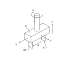
- FIG. 2 is a perspective view schematically showing a robot hand used for gripping a component in the component gripping system of FIG. 1
- FIG. 2 is a block diagram showing an example of an electrical configuration of a control device
- FIG. 2 is a flow chart showing an example of bin picking performed by the component gripping system of FIG. 1
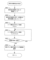
- 4B is a flowchart showing an example of patch image processing performed in the bin picking of FIG. 4A
- 4B is a flowchart illustrating an example of grasp inference performed in the bin picking of FIG. 4A.
- FIG. 4C is a flowchart showing an example of determination of a gripping target part executed in the gripping inference of FIG.
- FIG. 4C is a diagram schematically showing operations performed in the patch image processing of FIG. 4B;
- FIG. 4C is a diagram schematically showing operations performed in the patch image processing of FIG. 4B;
- FIG. 4C is a diagram schematically showing operations performed in the patch image processing of FIG. 4B;
- FIG. 4C is a diagram schematically showing operations performed in the patch image processing of FIG. 4B;
- FIG. 4C is a diagram schematically showing operations performed in the patch image processing of FIG. 4B;
- FIG. 4D is a diagram schematically showing actions performed in the grasping inference of FIG. 4C;
- FIG. 4D is a diagram schematically showing actions performed in the grasping inference of FIG. 4C;
- FIG. 4C is a diagram schematically showing actions performed in the grasping inference of FIG. 4C;
- FIG. 4D is a diagram schematically showing actions performed in the grasping inference of FIG. 4C;
- FIG. 4D is a diagram schematically showing actions performed in the grasping inference of FIG. 4C;
- 4 is a flow chart showing an example of a method of collecting learning data for a registration neural network;
- FIG. 4 is a diagram schematically showing an example of a position determination mask generated from patch images;
- FIG. 8B is an example of a flowchart for training an alignment neural network on the training data collected in FIG. 8A.
- FIG. 10 is a diagram schematically showing an example in which use of a mask is advantageous for calculation of a loss function;
- An example of a flow chart for causing a grasp classification neural network to perform learning An example of a flow chart for causing a grasp classification neural network to perform learning.
- An example of a flow chart for causing a grasp classification neural network to perform learning. 6 is a flowchart showing an example of a re-learning method for a grasp classification neural network of a grasp classification network unit; A modification of the grasp classification neural network of the grasp classification network unit.
- FIG. 1 is a plan view schematically showing an example of a component gripping system according to the present invention
- FIG. 2 is a perspective view schematically showing a robot hand used for gripping components in the component gripping system of FIG.
- the horizontal X direction, the horizontal Y direction orthogonal to the X direction, and the vertical Z direction are indicated as appropriate. These X, Y and Z directions constitute a global coordinate system.
- the component gripping system 1 includes a control device 3 and a work robot 5 , and the work robot 5 performs work (bin picking) based on control by the control device 3 .
- a parts bin 91 and a kitting tray 92 are arranged in the work space of the work robot 5 .
- the parts bin 91 has a plurality of storage compartments 911 for storing parts, and each storage compartment 911 stores a large number of parts.
- the kitting tray 92 has a plurality of partitioned storages 921 for storing components, and each partitioned storage 921 holds a predetermined number of components. Then, the working robot 5 grips the parts from the partitioned storage 911 of the parts bin 91 (bin picking) and transfers them to the partitioned storage 921 of the kitting tray 92 .
- a trash can 93 is arranged between the parts bin 91 and the kitting tray 92, and the working robot 5 discards the defective parts in the trash can 93 when a defective part is detected.
- the working robot 5 is a scalar robot having a robot hand 51 provided at its tip. and disposal of the parts to the trash box 93 are executed.
- the robot hand 51 has degrees of freedom in the X, Y, Z and .theta. directions.
- the ⁇ direction is the direction of rotation about a rotation axis parallel to the Z direction.
- the robot hand 51 also has two claws 511 arranged in the gripping direction G, and each claw 511 has a flat plate shape perpendicular to the gripping direction G.
- the robot hand 51 can expand/reduce the distance between the two claws 511 in the gripping direction G, and grips the part by sandwiching the part in the gripping direction G with these claws 511 .
- the gripping direction G is parallel to the X direction in FIG. 2, the gripping direction G can be inclined with respect to the X direction depending on the position of the robot hand 51 in the ⁇ direction.
- the component gripping system 1 includes two cameras 81 and 83 and a mass meter 85.
- the camera 81 is a plan view camera that captures an image of a large number of parts accumulated in the partition storage 911 of the parts bin 91 from the Z direction (upward), and faces the working space of the working robot 5 from the Z direction.
- This camera 81 captures a grayscale image (two-dimensional image) that indicates the imaging target (component) in luminance and a depth image (three-dimensional image) that indicates the distance to the imaging target.
- a phase shift method or a stereo matching method can be used as a specific method of acquiring a depth image.
- the camera 83 is a side-view camera that takes an image of the component gripped by the robot hand 51 from the Y direction, and is attached horizontally to the base of the robot hand 51 .
- This camera 83 captures a grayscale image (two-dimensional image) that indicates an imaging target (component) with luminance.
- the mass meter 85 measures the mass of the parts placed in the compartment storage 921 of the kitting tray 92 .
- FIG. 3 is a block diagram showing an example of the electrical configuration of the control device.
- the control device 3 is, for example, a personal computer provided with an arithmetic unit 31, a storage unit 35 and a UI (User Interface) 39.
- the calculation unit 31 is a processor including, for example, a CPU (Central Processing Unit), and has a main control unit 311 and an image processing unit 4 .
- the main control unit 311 and the image processing unit 4 are developed in the calculation unit 31 by executing a predetermined program.
- the main control unit 311 controls hardware such as the robot hand 51, the cameras 81 and 83, and the mass meter 85 described above, and the image processing unit 4 recognizes a component to be gripped by the robot hand 51. Perform image processing.
- the image processing section 4 has an image synthesizing section 41 , a patch image generating section 43 , an alignment network section 45 and a grip classification network section 47 . These functions are described in detail below.
- the storage unit 35 is a storage device such as a HDD (Hard Disk Drive) or SSD (Solid State Drive). memorize
- the UI 39 has input devices such as a keyboard and a mouse, and output devices such as a display. It displays an image according to the command on the display.
- FIG. 4A is a flow chart showing an example of bin picking performed by the component gripping system of FIG. 1
- FIG. 4B is a flow chart showing an example of patch image processing performed in the bin picking of FIG. 4A
- FIG. 4D is a flow chart showing an example of grip inference performed in the bin picking of FIG. 4A
- FIG. 4D is a flow chart showing an example of determination of a grip target part performed in the grip inference of FIG. 4C.
- step S101 of bin picking in FIG. 4A the camera 81 captures a plan view image of a large number of parts piled up in the partitioned storage 911 of the parts bin 91 .
- the grayscale image Ig and the depth image Id are captured as described above.
- the main control unit 311 transfers these images Id and Ig acquired from the camera 81 to the image synthesizing unit 41 of the image processing unit 4, and the image synthesizing unit 41 executes patch image processing (step S102).
- 5A to 5E are diagrams schematically showing operations performed in the patch image processing of FIG. 4B.
- the image synthesizing unit 41 In step S201 of the patch image processing in FIG. 4B, the image synthesizing unit 41 generates a synthetic image Ic (FIG. 5C) by synthesizing the grayscale image Ig (FIG. 5A) and the depth image Id (FIG. 5B).
- the grayscale image Ig is composed of a plurality of pixels PX arranged two-dimensionally in the X direction and the Y direction. is.
- a notation for specifying one pixel PX is used by a combination (m, n) of "m” indicating the row number and "n” indicating the column number, and the pixel PX ( m,n) has luminance Vg(m,n). Note that the brightness Vg(m, n) has a larger value as the corresponding portion becomes brighter.
- the depth image Id is image data composed of a plurality of pixels PX, similar to the grayscale image Ig, and indicating the depth (distance) of the pixels PX for each of the plurality of pixels PX. Similar notation is used in FIG. 5B as in FIG. 5A, and the pixel PX(m,n) of the depth image Id has the depth Vd(m,n). Note that the depth Vd(m, n) has a larger value as the depth of the corresponding portion is shallower (in other words, as the position of the opposing portion is higher).
- the composite image Ic is image data that is composed of a plurality of pixels PX, similar to the grayscale image Ig, and indicates a composite value Vc of the pixels PX for each of the plurality of pixels PX.
- the same notation as in FIG. 5A is also used in FIG. 5C, and the pixel PX(m,n) of the composite image Ic has the composite value Vc(m,n).
- the brightness Vg normalized by the maximum brightness is multiplied by the depth Vd (weight).
- the normalization is not essential, and the combined value Vc may be calculated by multiplying the brightness Vg as it is by the depth Vd (weight).
- the composite value Vc should be determined so as to depend on both the brightness Vg and the depth Vd.
- FIG. 5D shows experimental results of generating a composite image Ic from the grayscale image Ig and the depth image Id.
- the grayscale image Ig (before filtering) is two-dimensional image data obtained by the camera 81, and the grayscale image Ig (after filtering) is obtained by filtering predetermined components (high frequency components) of the two-dimensional image data obtained by the camera 81. 2D image data removed by Also, the depth image Id (before filtering) is three-dimensional image data acquired by the camera 81, and the depth image Id (before filtering) is the three-dimensional image data acquired by the camera 81 by filtering a predetermined component (high frequency component).
- the synthesized image Ic is a depth-weighted grayscale image obtained by synthesizing the filtered grayscale image Ig and the depth image Id according to the above equation.
- range elliptical range
- Composite image Ic the grayscale image Ig (after filtering).
- the part that had been attached does not appear in the composite image Ic. This is because the part in question has a deep depth (in other words, it has a low height) and the brightness Vg of the part in question is given a small weight.
- the combination of the grayscale image Ig and the depth image Id has the effect of highlighting the components at high positions.
- the filter used in FIG. 5D is not essential, and similar effects can be obtained even if it is omitted as appropriate.
- the composite image Ic generated in step S201 of FIG. 4B is output from the image composition unit 41 to the patch image generation unit 43, and the patch image generation unit 43 executes the image processing of steps S202 to S204 on the composite image Ic. do.
- the specific content of this image processing is illustrated in FIG. 5E.
- the binary composite image Ic is obtained by binarizing the composite image Ic with a predetermined threshold value. In this binary composite image Ic, a closed region having high brightness (white) appears corresponding to the part.
- the patch image generation unit 43 performs labeling in which different labels (numbers) are associated with the components P (closed regions Rc) of the binary composite image Ic.
- a clipping range Rc for clipping an image including the part P from the binary composite image Ic is set.
- the cutout range Rc is set so as to represent the position of the robot hand 51 when the part P is gripped.
- This cutout range Rc corresponds to a gripping target range (gripping target range) of the robot hand 51, and the robot hand 51 can grip the part P existing in the cutout range Rc.
- the portion corresponding to the two claws 511 of the robot hand 51 facing the part P(2) from above for gripping the part P is the white part of the cutout range Rc.
- a solid line indicates a locus along which both ends of each claw 511 move is indicated by a white dashed line (parallel to the X direction).
- the claw 511 is parallel to the Y direction, and the rotation angle of the robot hand 51 in the ⁇ direction is zero degrees. That is, the setting of the cutout range Rc is performed in a state where the rotation angle of the robot hand 51 in the ⁇ direction is zero degrees.
- the patch image generation unit 43 acquires the image of the clipping range Rc from the binary composite image Ic as the patch image Ip (patch image generation). This patch image Ip is generated for each part P labeled in step S203.
- FIG. 4A when the patch image processing in step S102 is completed, the grip inference in step S103 (FIG. 4C) is executed.
- 6A-6C and 7 are diagrams schematically illustrating the actions performed in the grasp inference of FIG. 4C. 4C
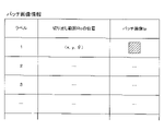
- patch image information (FIG. 6A) indicating a plurality of patch images Ip obtained by the patch image processing in step S102 is output from the image synthesizing unit 41 to the alignment network unit 45. be done.
- the patch image information indicates the patch image Ip, the label number of the patch image Ip, and the position of the cutout range Rc of the patch image Ip in association with each other.
- the shape of the cutout range Rc is the same for each patch image Ip, and the position (cutout position) of the cutout range Rc is specified by the X, Y, and ⁇ coordinates of the geometric center of gravity of the cutout range Rc.
- step S301 of FIG. 4C the alignment network unit 45 resets the count value for counting the labels of the plurality of patch images Ip indicated by the patch image information to zero (step S301). is incremented (step S302).
- step S303 the alignment network unit 45 determines whether the area of the object (white closed area) included in the patch image Ip with the current count value is appropriate. Specifically, each of the lower threshold and the upper threshold greater than the lower threshold is compared with the object area. Then, if the object area is smaller than the lower threshold or larger than the upper threshold, it is determined that the object area is inappropriate ("NO” in step S303), and the process returns to step S302. On the other hand, if the object area is greater than or equal to the lower threshold and less than or equal to the upper threshold, it is determined that the object area is appropriate ("YES" in step S303), and the process proceeds to step S304.
- step S304 the alignment network unit 45 calculates a correction amount for correcting the position of the clipping range Rc based on the patch image Ip with the current count value. That is, the alignment network section 45 has an alignment neural network, and this alignment neural network outputs correction amounts ( ⁇ x, ⁇ y, ⁇ ) of the clipping range Rc when the patch image Ip is input. The relationship between the patch image Ip and the correction amount of the cutout range Rc will be described with reference to FIG. 6C.
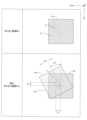
- the column of "Clipping range Rc" in FIG. 6C shows the clipping range Rc and the patch image Ip that has been clipped from the clipping range Rc.
- a corrected cropping range Rcc corrected according to the amounts ( ⁇ x, ⁇ y, ⁇ ) is superimposed on these.
- the cutout range Rc and the corrected cutout range Rcc have the same shape, and each of the following operations: Parallel movement in the X direction by the correction distance ⁇ x... X direction parallel operation ⁇ Parallel movement in the Y direction by the correction distance ⁇ y...Y direction Parallel operation/rotational movement in the ⁇ direction by a correction angle ⁇
- the cutout range Rc in which the ⁇ direction rotation operation is performed matches the corrected cutout range Rcc.
- the positional deviation between the center of the corrected cutout range Rcc and the part P is improved.
- the correction of the cutout range Rc is a correction for improving the positional deviation between the cutout range Rc and the part P, more specifically, a correction for converting the cutout range Rc into a corrected cutout range Rcc so that the part P is centered.
- the alignment neural network of the alignment network unit 45 corrects the clipping range Rc of the patch image Ip for the input of the patch image Ip to calculate the corrected clipping range Rcc by the correction amount ( ⁇ x, ⁇ y , ⁇ ).
- the calculation for correcting the clipping range Rc by the correction amount and converting it to the corrected clipping range Rcc is performed by using a rotation matrix that rotates ⁇ in the ⁇ direction, and a parallel translation of ⁇ y in the Y direction while translating ⁇ x in the X direction. can be done by multiplying it with the translation matrix Also, if it is necessary to consider enlargement/reduction of the image, the scaling matrix may be further multiplied.
- step S305 the alignment network unit 45 corrects the cutout range Rc based on the correction amount output by the alignment neural network, thereby creating a corrected cutout range Rcc, and correcting the cutout range Rcc from the binary composite image Ic.
- An image of the range Rcc is acquired as a correction patch image Ipc (correction patch image generation).
- steps S302 to S305 are repeated until steps S302 to S305 are completed for all labels (in other words, all patch images Ip) included in the patch image information (until "YES" in step S306).
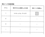
- correction patch image information (FIG. 6B) indicating a plurality of correction patch images Ipc is output from the alignment network unit 45 to the grip classification network unit 47.
- FIG. 6B the correction patch image information indicates the correction patch image Ipc, the label number of the correction patch image Ipc, and the position of the correction cutout range Rcc of the correction patch image Ipc in association with each other.
- the shape of the corrected cutout range Rcc is the same for each corrected patch image Ipc, and the position (cutout position) of the corrected cutout range Rcc is specified by the X, Y, and ⁇ coordinates of the geometric center of gravity of the corrected cutout range Rcc.
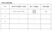
- step S307 the gripping classification network unit 47 calculates the gripping success probability for each of the plurality of correction patch images Ipc indicated in the correction patch image information. Specifically, with the robot hand 51 positioned at the position (x + ⁇ x, y + ⁇ y, ⁇ + ⁇ ) of the correction cutout range Rcc, an attempt was made to grasp the part P indicated by the correction patch image Ipc cut out in the correction cutout range Rcc. A success probability (grasping success probability) in the case is calculated. That is, the grip classification network unit 47 has a grip classification neural network, and this grip classification neural network outputs the grip success probability corresponding to the corrected patch image Ipc when the corrected patch image Ipc is input. Thus, the gripping success probability information shown in FIG.
- the grasping success probability information includes the correction patch image Ip, the label number of the correction patch image Ipc, the position of the correction cut-out range Rcc of the correction patch image Ipc, and the correction patch image Ipc. It is shown in association with the gripping success probability. Although the gripping success probability is indicated by a value between 0 and 1 in the example of FIG. 7, it may be indicated by a percentage.
- step S ⁇ b>308 the main control unit 311 determines the part P to be gripped based on the gripping success probability information output from the gripping classification network unit 47 .
- each correction patch image Ipc of the gripping success probability information is sorted in descending order according to the gripping success probability (step S401). That is, the corrected patch image Ipc having a higher grasping success probability is sorted at a higher rank.
- correction patch images Ipc with the same gripping success probability are sorted in descending order according to the object area included in the correction patch images Ipc. That is, correction patch images Ipc having larger object areas are sorted higher.
- the sort order count value is reset to zero, and in step S404, the count value is incremented.
- step S405 it is determined whether the part P included in the correction patch image Ipc of the current count value is close to the end of the partition storage 911 (container) of the part bin 91. Specifically, if the distance between the position of the correction clipping range Rcc from which the correction patch image Ipc is clipped and the wall surface of the partition storage 911 is less than a predetermined value, it is close to the end of the container ("YES" in step S405). ”), and the process returns to step S404. On the other hand, if the distance is equal to or greater than the predetermined value, it is determined that the object is not close to the edge of the container ("NO" in step S405), and the process proceeds to step S406. In step S406, the correction patch image Ipc of the current count value is selected as one correction patch image Ipc indicating the part P to be gripped. Then, return to the flow chart of FIG. 4A.
- step S104 of FIG. 4A the robot hand 51 moves to the position indicated by the correction cutout range Rcc corresponding to the one correction patch image Ipc selected in step S103, and grips the part P indicated by the one correction patch image Ipc. do.
- step S105 the image of the part P gripped by the robot hand 51 is captured by the camera 83.
- step S106 the main control unit 311 detects the part P gripped by the robot hand 51 from the image captured by the camera 83. judge. Further, the main control unit 311 determines whether the number of the gripped parts P is one (step S107), and if not one ("NO" in step S107), the robot hand 51 The part P is returned to the partition storage 911 of the part bin 91 (step S108).
- step S107 When the number of gripped parts P is one ("YES" in step S107), the main control unit 311 determines whether the gripped part P is normal (step S109). ), if there is an abnormality such as the area indicating the part P being too small ("NO” in step S109), the robot hand 51 discards the part P in the trash box 93 (step S110).
- step S109 the main control unit 311 causes the robot hand 51 to place the part P in the compartment storage 921 of the kitting tray 92 (step S111). ). Subsequently, the main controller 311 measures the mass with the mass meter 85 (step S112), and determines whether the mass indicated by the mass meter 85 is appropriate (step S113). Specifically, it can be determined based on whether the mass corresponding to the part P placed on the kitting tray 92 has increased. Then, if the mass is not appropriate (“NO” in step S113), the main control unit 311 notifies the operator of the abnormality using the UI 39, and if the mass is appropriate (“NO” in step S113). YES"), the main control unit 311 returns to step S101.
- the alignment network unit 45 calculates correction amounts ( ⁇ x, ⁇ y, ⁇ ) for correcting the clipping range Rc based on the patch image Ip clipped from the clipping range Rc.
- the alignment network unit 45 uses the alignment neural network to calculate the correction amount of the clipping range Rc from the patch image Ip.
- a method of making the alignment neural network learn the relationship between the patch image Ip and the correction amount of the clipping range Rc will be described.
- FIG. 8A is a flow chart showing an example of a method of collecting learning data for a registration neural network.
- This flowchart is executed by the calculation unit 31 of the control device 3 .
- the computing unit 31 is configured with a simulator that executes bin picking in a component gripping system 1 that is virtually constructed by computation (hereinafter referred to as “virtual component gripping system 1” as appropriate).
- This simulator virtually executes the operation of the robot hand 51 gripping the part P from the partition storage 911 of the part bin 91 by computation based on physical parameters such as gravitational acceleration and friction coefficient.
- step S501 it is confirmed whether the number of data necessary for learning has been acquired. This required number can be preset, for example, by an operator. If the required number of data has been acquired ("YES" in step S501), the flowchart in FIG. 8A ends. ), the process proceeds to step S502.
- step S502 it is determined whether or not sufficient parts P are stored in the partition storage 911 of the part bin 91 arranged in the virtual part grasping system 1. Specifically, it can be determined based on whether the number of parts P is equal to or greater than a predetermined number. When the number of parts P in the partitioned storage 911 of the parts bin 91 is less than the predetermined number ("NO" in step S502), the number of parts P in the partitioned storage 911 of the parts bin 91 is reset. is increased to the initial value (step S503), and the process returns to step S501. On the other hand, if the number of parts P in the partitioned storage 911 of the parts bin 91 is equal to or greater than the predetermined number ("YES" in step S502), the process proceeds to step S504.
- step S504 a composite image Ic is generated in the virtual part grasping system 1 in the same manner as in the case of the real part grasping system 1 described above. Subsequently, this synthesized image Ic is binarized to generate a binary synthesized image Ic, and each component P included in this binary synthesized image Ic is labeled (step S505). . Then, a clipping range Rc is set for each labeled part P, and a patch image Ip is clipped (step S506).
- step S507 the count value for counting each patch image Ip is reset, and at step S508, the count value is incremented. Then, in the same manner as described above, it is determined whether the area of the object (white closed region) included in the patch image Ip with the current count value is appropriate (step S509). If the area of the object is inappropriate (“NO” in step S509), the process returns to step S508. If the area of the object is appropriate (“YES” in step S509), step S510 proceed to
- FIG. 8B is a diagram schematically showing an example of a position determination mask generated from patch images.
- This position determination mask Mp has a contour having the same shape as the patch image Ip (in other words, the cutout range Rc).
- a reference pattern Pr is arranged.
- the component reference pattern Pr is generated so as to have the number of pixels in each of the vertical and horizontal directions of the component P (in other words, white closed area) included in the patch image Ip.
- This position determination mask Mp is a model of an ideal patch image Ip in which the part P is positioned at the center. Then, the patch image Ip and the position determination mask Mp generated from the patch image Ip are associated and stored in the patch image list (step S511).
- Step S501 Steps S501 to S511 are repeated until the required number of data is acquired, in other words, until the number of pairs of the patch image Ip and the position determination mask Mp stored in the patch image list reaches the required number. executed.
- FIG. 9A is an example of a flow chart for making the registration neural network learn the learning data collected in FIG. 8A. This flowchart is executed by the calculation unit 31 of the control device 3 . In step S601, it is determined whether the number of times of learning has reached a predetermined number. This predetermined number can be set in advance by the operator, for example.
- step S602 the unlearned patch image Ip selected from the patch image list is forward-propagated to the alignment neural network of the alignment network unit 45.
- the neural network of the alignment network unit 45 outputs the correction amount ( ⁇ x, ⁇ y, ⁇ ) corresponding to the patch image Ip.
- the alignment network unit 45 cuts out the binary composite image Ic (generated in step S505) within the corrected cutout range Rcc obtained by correcting the cutout range Rc by this correction amount, thereby generating the corrected patch image Ipc (step S603).
- step S604 the alignment network unit 45 superimposes the position determination mask Mp corresponding to the patch image Ip selected in step S602 and the correction patch image Ipc so that their outlines match each other, thereby forming the position determination mask Mp.
- a mean square error between the component reference pattern Pr and the component P included in the correction patch image Ipc is calculated as a loss function.
- step S605 the parameters of the alignment neural network are updated by backpropagating this loss function in the alignment neural network (error backpropagation).
- FIG. 9B is a diagram schematically showing an example in which the use of a mask is advantageous in calculating the loss function.
- the part P included in the correction patch image Ipc shown in FIG. 9B has a zigzag shape, and it is difficult to appropriately obtain the principal axis angle from the moment of the image of this part P. Therefore, the position determination mask Mp is used here from the viewpoint of handling parts P having various shapes.
- step S606 of the patch images Ip stored in the patch image list, the patch images Ip (test data) reserved in advance for testing and not used for learning are forward-propagated to the alignment neural network whose parameters have been updated. , the correction amount is calculated. Then, based on this correction amount, the loss function is calculated using the position determination mask Mp corresponding to the test data in the same manner as in steps S603 and S604.
- the calculation unit 31 stores the loss function calculated in step S606 each time step S606 is executed, and calculates the minimum value among the plurality of loss functions thus stored. Then, the calculation unit 31 checks whether the most recently calculated loss function has updated the minimum value. Especially in step S607, it is determined whether the minimum value has not been updated ten times in a row, that is, whether a loss function larger than the minimum value has been calculated. Then, if a loss function less than or equal to the minimum value has been calculated in the last 10 times ("NO" in step S607), the process returns to step S601. If calculated ("YES" in step S607), the flowchart of FIG. 9A ends. Note that the number of times is not limited to 10 times, and can be changed as appropriate.
- the grasping classification network unit 47 classifies the part P included in the correction patch image Ipc into the position indicated by the correction patch image Ipc.
- a gripping success probability when gripped by the robot hand 51 is calculated.
- the grip classification network unit 47 uses a grip classification neural network to calculate the grip success probability from the corrected patch image Ipc.
- Figs. 10A to 10C are an example of a flow chart for causing the grasp classification neural network to perform learning. This flowchart is executed by the calculation unit 31 of the control device 3 .
- a simulator for constructing the virtual part gripping system 1 is used in learning of the gripping classification neural network as in the learning of the alignment neural network described above.
- steps S701-S709 of FIG. 10A are similar to steps S501-S509 of FIG. 8A, except for the following points. That is, in step S701, it is determined whether or not the number of times of learning has reached a predetermined number, not the number of data acquisitions. This predetermined number can be set in advance by the operator, for example.
- step S710 when one patch image Ip having an appropriate object area is selected by executing steps S701 to S709, the alignment network unit 45 uses the alignment neural A correction amount corresponding to the patch image Ip is calculated using a network (step S710), and the patch image Ip and the correction amount are associated and stored in a correction amount list (step S711). Steps S708 to S711 are repeated until the count value reaches the maximum ("YES” in step S712), and pairs of patch images Ip and correction amounts are sequentially stored in the correction amount list. When the count value reaches the maximum (“YES” in step S712), the process proceeds to step S712 in FIG. 10B.
- step S712 the alignment network unit 45 corrects the clipping range Rc of the patch image Ip based on the correction amount to generate the corrected clipping range Rcc, and performs processing for generating the corrected patch image Ipc based on the corrected clipping range Rcc. , for each pair of the patch image Ip and the correction amount stored in the correction amount list. As a result, a plurality of correction patch images Ipc are generated.
- the specific procedure for generating the correction patch image Ipc is as described above.
- step S713 it is confirmed whether the number of data necessary for learning has been acquired. This required number can be preset, for example, by an operator. If the required number of data has already been acquired ("YES" in step S713), the process proceeds to step S717 (FIG. 10C), which will be described later. ), the process proceeds to step S714.
- step S714 one correction patch image Ipc is randomly selected (for example, based on the output of a random number generator) from among the plurality of correction patch images Ipc generated in step S712. Then, in step S715, in the virtual part gripping system 1, the robot hand 51 positioned at the position of the one correction patch image Ipc attempts to grip the part P included in the one correction patch image Ipc. The position of the correction patch image Ipc corresponds to the position of the correction cutout range Rcc obtained by cutting out the correction patch image Ipc. Then, the success/failure result of the gripping trial (1 for success, 0 for failure) is stored in the success/failure result list in association with the correction patch image Ipc (step S716). Return to step S701.
- step S713 if it is determined that the required number of data has been acquired (YES) in step S713, the process proceeds to step S717 in FIG. 10C as described above.
- step S717 a horizontally inverted corrected patch image Ipc obtained by horizontally reversing the corrected patch image Ipc, a vertically reversed corrected patch image Ipc obtained by vertically reversing the corrected patch image Ipc, and a horizontally reversed corrected patch image Ipc are horizontally and vertically reversed.
- a vertically-horizontally reversed corrected patch image Ipc is generated.
- three types of images ie, the horizontally-reversed corrected patch image Ipc, the vertically-reversed corrected patch image Ipc, and the vertically-horizontally reversed corrected patch image Ipc are prepared for each corrected patch image Ipc in the success/failure result list. That is, a plurality of correction patch images Ipc are prepared in a number that is three times the number of correction patch images Ipc stored in the success/failure result list.
- each of the plurality of correction patch images Ipc generated in step S717 is forward-propagated in the grasp classification neural network of the grasp classification network unit 47, and the grasp success probability is calculated for each correction patch image Ipc.
- the average value of the grasping success probability of each of the horizontal-reversed corrected patch image Ipc, the vertically-reversed corrected patch image Ipc, and the vertically-horizontally reversed corrected patch image Ipc generated from the same corrected patch image Ipc is calculated.
- the average value of the gripping success probability is calculated for each correction patch image Ipc stored in the success/failure result list.
- step S720 one of "0", “1” and “2” is generated by a random number generator. Then, when “0” is obtained in the random number generation, one correction patch image Ipc is randomly selected from among the correction patch images Ipc for which the gripping success probability has been calculated in step S719 (step S721). When “1” is obtained by random number generation, one correction patch image Ipc whose grip success probability is closest to "0.5” (in other words, 50%) is selected from among the correction patch images Ipc. If it is selected (step S722) and "2" is obtained by random number generation, one correction patch image Ipc with the highest gripping success probability is selected from among the correction patch images Ipc (step S723).
- step S724 in the virtual part gripping system 1, the robot hand 51 positioned at the position of the one correction patch image Ipc attempts to grip the part P indicated by the one correction patch image Ipc. Then, a loss function is calculated based on the success or failure result of component gripping (1 for success, 0 for failure) and the average gripping success probability calculated for the one correction patch image Ipc in step S719. be. Various well-known functions such as cross-entropy error can be used as the loss function.
- the calculation unit 31 stores the loss function calculated in step S725 each time step S725 is executed, and calculates the minimum value among the plurality of loss functions thus stored. Then, the calculation unit 31 checks whether the most recently calculated loss function has updated the minimum value. In particular, in step S726, it is determined whether the minimum value has not been updated ten times in a row, that is, whether a loss function greater than the minimum value has been calculated. If a loss function less than or equal to the minimum value has been calculated in the last 10 times ("NO" in step S726), the result of gripping success or failure in step S724 is associated with one correction patch image Ipc. are stored in the success/failure result list (step S727).
- step S728 the loss function calculated in step S725 is back-propagated in the gripping classification neural network (error backpropagation) to update the parameters of the gripping classification neural network.
- step S726 if a loss function larger than the minimum value is calculated ten times in a row ("NO"), the process returns to step S701 in FIG. 10A. Note that the number of times is not limited to 10 times, and can be changed as appropriate.
- a correction patch image Ipc including a part P at a position where one part P can be gripped with a high probability of success can be obtained based on the correction amounts ( ⁇ x, ⁇ y, ⁇ ) obtained from the patch image Ip. Therefore, there is no need to calculate the gripping success probability for each of the plurality of patch images Ip corresponding to the case where the robot hand 51 grips one part P at a plurality of positions (especially rotational positions) different from each other. In this way, it is possible to reduce the computational load required to calculate the grasping success probability when the robot hand 51 tries to grasp the part P.
- the alignment network unit 45 uses the positional difference between the position determination mask Mp indicating the appropriate position of the part P in the cutout range Rc and the part P included in the patch image Ip as teacher data.
- the relationship between the image Ip and the correction amount ( ⁇ x, ⁇ y, ⁇ ) is learned (steps S601 to S607).
- the alignment network unit 45 also generates a patch image Ip based on the shape of the part P included in the patch image Ip (step S510). With such a configuration, learning can be performed using an appropriate position determination mask Mp adapted to the shape of the part P.
- FIG. 5
- the alignment network unit 45 back-propagates the mean square error of the position between the part P included in the patch image Ip and the position determination mask Mp (the part reference pattern Pr thereof) as a loss function to obtain the patch image Ip.
- Learning is executed to update the parameters that define the relationship with the correction amounts ( ⁇ x, ⁇ y, ⁇ ) (steps S604 and S605).
- the alignment network unit 45 repeats learning while changing the patch image Ip (steps S601 to S607). With such a configuration, highly accurate learning results can be obtained.
- the alignment network unit 45 terminates learning when the number of repetitions of learning reaches a predetermined number (step S601). Also, the registration network unit 45 terminates learning according to the result of determining the state of convergence of the loss function in step S607. Specifically, when the minimum value of the loss function is not updated a predetermined number of times (10 times) in succession, it is determined that the loss function has converged, and learning ends.
- the main controller 311 image acquisition unit
- the main controller 311 acquires a grayscale image Ig (brightness image) representing the plurality of parts P and the depth image Id representing the plurality of parts P
- the grayscale image acquired by the main controller 311 An image synthesizing unit 41 is provided that generates a synthesized image Ic by synthesizing the scale image Ig and the depth image Id.
- the patch image generation unit 43 generates the patch image Ip from the composite image Ic and inputs it to the alignment network unit 45 . That is, the synthetic image Ic is generated by synthesizing the grayscale image Ig and the depth image Id respectively representing the plurality of parts P.
- the shape of the component P at a relatively high position among the plurality of components P tends to remain, which is advantageous for recognizing such a component (in other words, a component with a high probability of successful gripping).
- the component gripping system 1 corresponds to an example of the "component gripping system” of the present invention
- the control device 3 corresponds to an example of the "image processing device” of the present invention
- the main control unit 311 corresponds to an example of the "image acquiring section” of the present invention
- the image synthesizing section 41 corresponds to an example of the “image synthesizing section” of the present invention
- the patch image generating section 43 corresponds to the "patch image generating section” of the present invention.
- the alignment network unit 45 corresponds to an example of the "alignment unit” of the present invention
- the alignment network unit 45 corresponds to an example of the "corrected image generation unit” of the present invention
- the grip classification network unit 47 corresponds to an example of the "holding and classifying section” of the present invention
- the robot hand 51 corresponds to an example of the "robot hand” of the present invention
- the partitioned storage 911 of the parts bin 91 corresponds to an example of the "container” of the present invention.
- the composite image Ic corresponds to an example of the "storage component image” of the present invention
- the depth image Id corresponds to an example of the "depth image” of the present invention
- the grayscale image Ig corresponds to the "brightness image” of the present invention.
- the patch image Ip corresponds to an example of the "first patch image” of the invention
- the correction patch image Ipc corresponds to an example of the "second patch image” of the invention
- the position determination mask Mp corresponds to an example of the "second patch image” of the invention.
- the part P corresponds to an example of the "part” of the present invention
- the cutout range Rc corresponds to an example of the "target range” of the present invention
- the correction amount ( ⁇ x , ⁇ y, ⁇ ) correspond to an example of the “correction amount” of the present invention.
- step S105 the component P gripped by the robot hand 51 may be imaged by the camera 83 from different directions to acquire a plurality of side view images.
- These side-view images can be obtained, for example, by imaging the component P while rotating the robot hand 51 that grips the component P in the ⁇ direction.
- confirmation of the number of parts P in step S107 and confirmation of abnormalities (too small area) of parts P in step S109 can be performed from a plurality of directions.
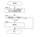
- FIG. 11 is a flow chart showing an example of the re-learning method of the grip classification neural network of the grip classification network unit. This flowchart is executed by the main control unit 311, for example, when the planned bin picking is finished.
- step S801 the main control unit 311 detects an abnormality based on the side-view image (“NO” in steps S107 and S108) or an abnormality based on mass measurement (“NO” in step S113) in the bin picking performed in the past. Check the detected history. Then, if the number of times an abnormality is detected is equal to or greater than a predetermined number ("YES" in step S802), re-learning of the gripping classification neural network of the gripping classification network unit 47 is executed (step S803). In this re-learning, the correction patch image Ipc indicating the part P in which the abnormality was detected and the gripping success/failure result (that is, failure) are used as teaching data.
- an error function is calculated based on the gripping success/failure probability obtained by forward propagation of the corrected patch image Ipc through the gripping classification neural network and the gripping success/failure result (failure), and the error function is calculated in the gripping classification neural network.
- Backpropagation updates the parameters of the grasp classification neural network (relearning).
- the gripping classification neural network is caused to re-learn based on the results of acquiring the gripping state information (side-view image, mass) for the part P gripped by the robot hand 51 .
- the gripping classification neural network is re-learned according to the actual success or failure of gripping the selected part P based on the gripping success probability obtained for the correction patch image Ipc, and the gripping success probability by the gripping classification neural network is obtained.
- Fig. 12 is a modified example of the grip classification neural network of the grip classification network unit.
- a multilayer convolutional neural network 472 and a fully connected layer 473 are arranged in series.
- a spatial attention module 474 and a channel attention module 475 are provided on the output side of each convolutional neural network 472, and the feature amount map output from the convolutional neural network 472 is used for the spatial attention module 474 and the channel attention module.
- the attention mask Ma that the spatial attention module 474 adds to the feature amount map has two regions of interest Pg and Pp passing through the center position of the corrected patch image Ipc (in other words, the corrected cropping range Rcc). That is, in the attention mask Ma, the weights of the attention areas Pg and Pp are higher than the weights of the other areas, and these weights are added to the feature amount map.
- the attention area Pg is parallel to the gripping direction G
- the attention area Pp is orthogonal to the gripping direction G.
- the attention area Pp is parallel to the long axis direction of the part P.
- this attention mask Ma is divided into an attention area Pp corresponding to the ideal position of the part P in the correction patch image Ipc and an attention area Pg corresponding to the path along which the claw 511 of the robot hand 51 approaches the part P. Focus on it.
- the attention mask Ma having such a configuration is added to the feature map output from the convolutional neural network 472 to weight the feature map. Therefore, the angle of the long axis direction of the part P with respect to the gripping direction G and the status of the movement path of the robot hand 51 gripping the part P (presence or absence of other parts) can be accurately reflected in the determination by the gripping classification neural network. can be done.
- the gripping classification network unit 47 uses the convolutional neural network 472 to calculate the gripping success probability from the corrected patch image Ipc. This makes it possible to accurately calculate the gripping success probability from the corrected patch image Ipc.
- the grasp classification network unit 47 weights the feature map output from the convolutional neural network 472 by adding an attention mask Ma to the feature map.
- the attention mask Ma includes a region of interest Pg that extends in the gripping direction G in which the robot hand 51 grips the part P and passes through the center of the correction patch image Ipc, and a region of interest Pg that extends perpendicularly to the gripping direction G and passes through the center of the correction patch image Ipc. This indicates that attention is paid to the attention area Pp. This makes it possible to accurately calculate the gripping success probability while taking into account the influence of the orientation of the component P and the surrounding conditions of the component P (the presence or absence of other components P) on gripping by the robot hand 51. .
- the method of generating the composite image Ic is not limited to the example using the above formula, and the composite value Vc of the composite image Ic is calculated by weighting the brightness Vg of the grayscale image Ig by the depth Vd of the depth image Id. You may generate the synthetic image Ic by other formulas.
- the grayscale image Ig and the depth image Id are synthesized to generate the synthesized image Ic.
- the reversed grayscale image Ig luminance image
- the composite image Ic when gripping a component P having a black-plated surface, it is preferable to generate the composite image Ic using the inverted grayscale image Ig.
- the patch image Ip may be cut out from the composite image Ic without executing the binarization.
- the corrected patch image Ipc may be cut out from the composite image Ic without executing the binarization.
- the cutout range Rc can be set so that the geometric center of gravity of the cutout range Rc coincides with the geometric center of gravity of the part P.
- the cutout range Rc may be set so as to include the target part P.
- the specific configuration of the robot hand 51 is not limited to the above example.
- the number of claws 511 of the robot hand 51 is not limited to two, and may be three or more.
- a robot hand 51 that attracts by negative pressure or magnetic force can also be used.
- the clipping range Rc can be set in the range to be gripped by the robot hand 51, and the patch image Ip can be clipped from the clipping range Rc.
- the patch image Ip is created from the synthesized image Ic obtained by synthesizing the grayscale image Ig and the depth image Id.
- the patch image Ip is created from one of the grayscale image Ig and the depth image Id, and the correction amount ( ⁇ x, ⁇ y, ⁇ ) is calculated by the registration network unit 45 based on the patch image Ip. Calculation of the gripping success probability by
Abstract
一の部品Pに対して設定された切り出し範囲Rc(対象範囲)の画像を切り出したパッチ画像Ip(第1パッチ画像)が位置合わせネットワーク部45に入力されると、パッチ画像Ipに含まれる一の部品Pに対して切り出し範囲Rcの位置を補正するための補正量(Δx,Δy,Δθ)が位置合わせネットワーク部45から出力される(ステップS304)。そして、この補正量(Δx,Δy,Δθ)だけ切り出し範囲Rcを補正した補正切り出し範囲Rccの画像を合成画像Ic(収納部品画像)から切り出した、一の部品Pを含む補正パッチ画像Ipc(第2パッチ画像)が生成されて(ステップS305)、この補正パッチ画像Ipcについて把持成功確率が算出される(ステップS307)。
Description
この発明は、容器に収納された複数の部品をロボットハンドによって把持する技術に関し、特にビンピッキングに対して好適に適用できる。
非特許文献1には、ビンピッキングにおいて、ロボットハンドによって部品を把持した場合の把持成功確率を算出する技術が開示されている。具体的には、ビン内に堆積する複数の部品を撮像したビン画像から、対象部品を含む所定サイズのパッチ画像が切り出される。そして、このパッチ画像の位置(切り出し位置)に位置するロボットハンドによって、パッチ画像に含まれる対象部品の把持を試行した場合の把持成功確率が算出される。かかる把持成功確率は、異なる対象部品のそれぞれについて算出される。
さらに、部品を把持するロボットの位置成分としては、X方向あるいはY方向といった並進方向のみならず、回転方向も存在する。そこで、ロボットの回転位置の違いを反映させるために、ビン画像を回転させる演算を行うことで、互いに異なる角度に対応した複数のビン画像が生成され、複数のビン画像のそれぞれについて、パッチ画像の切り出しと、把持成功確率の算出とが実行される。
Improving DataEfficiency of Self-supervised Learning for Robotic Grasping (2019)
上記の方法によれば、ロボットハンドの回転角度の数と対象部品の数とを乗じた枚数のパッチ画像が取得されて、各パッチ画像について把持成功確率が算出される。そのため、演算負荷が過大になるという問題があった。
この発明は上記課題に鑑みなされたものであり、ロボットハンドによって部品の把持を試行した場合の把持成功確率の算出に要する演算負荷を低減可能とする技術の提供を目的とする。
本発明に係る画像処理装置は、容器に収納された複数の部品を示す収納部品画像に含まれる複数の部品のうちの一の部品に対して設定された対象範囲の画像を切り出した第1パッチ画像が入力されると、第1パッチ画像に含まれる一の部品に対して対象範囲の位置を補正するための補正量を出力する位置合わせ部と、補正量だけ対象範囲を補正した範囲の画像を収納部品画像から切り出した、一の部品を含む第2パッチ画像を生成する補正画像生成部と、第2パッチ画像が設定された範囲に位置するロボットハンドにより第2パッチ画像に含まれる一の部品の把持を試行した場合の把持成功確率を算出する把持分類部とを備える。
本発明に係る画像処理方法は、容器に収納された複数の部品を示す収納部品画像に含まれる複数の部品のうちの一の部品に対して設定された対象範囲の画像を切り出した第1パッチ画像が入力されると、第1パッチ画像に含まれる一の部品に対して対象範囲の位置を補正するための補正量を出力する工程と、補正量だけ対象範囲を補正した範囲の画像を収納部品画像から切り出した、一の部品を含む第2パッチ画像を生成する工程と、第2パッチ画像が設定された範囲に位置するロボットハンドにより第2パッチ画像に含まれる一の部品の把持を試行した場合の把持成功確率を算出する工程とを備える。
このように構成された画像処理装置および方法では、一の部品に対して設定された対象範囲の画像を切り出した第1パッチ画像が入力されると、第1パッチ画像に含まれる一の部品に対して対象範囲の位置を補正するための補正量が出力される。そして、この補正量だけ対象範囲を補正した範囲の画像を収納部品画像から切り出した、一の部品を含む第2パッチ画像が生成されて、この第2パッチ画像について把持成功確率が算出される。したがって、高い成功確率で一の部品を把持できる位置に部品を含む第2パッチ画像を、第1パッチ画像から求めた補正量に基づき得ることができる。そのため、ロボットハンドが互いに異なる複数の位置(特に回転位置)で一の部品を把持する場合に対応する複数のパッチ画像のそれぞれについて把持成功確率を算出する必要が無い。こうして、ロボットハンドによって部品の把持を試行した場合の把持成功確率の算出に要する演算負荷を低減することが可能となっている。
また、位置合わせ部は、対象範囲における部品の適正位置を示す位置判定マスクと、第1パッチ画像に含まれる部品との位置の差を教師データとして、第1パッチ画像と補正量との関係を学習するように、画像処理装置を構成してもよい。かかる構成では、第1パッチ画像が示す部品の適正位置からのずれを位置判定マスクによって簡便に評価しつつ学習を行うことができる。
また、位置合わせ部は、第1パッチ画像に含まれる部品の形状に基づき位置判定マスクを生成するように、画像処理装置を構成してもよい。かかる構成では、部品の形状に即した適切な位置判定マスクを用いて学習を行うことができる。
また、位置合わせ部は、第1パッチ画像に含まれる部品と位置判定マスクとの位置の平均二乗誤差を損失関数として誤差逆伝搬させて、第1パッチ画像と補正量との関係を規定するパラメーターを更新する学習を実行するように、画像処理装置を構成してもよい。かかる構成では、第1パッチ画像が示す部品の適正位置からのずれを平均二乗誤差によって的確に評価しつつ学習を行うことができる。
また、位置合わせ部は、第1パッチ画像を変更しつつ学習を繰り返すように、画像処理装置を構成してもよい。かかる構成では、高精度な学習結果を得ることができる。
なお、学習を終了する条件としては、種々想定できる。例えば、位置合わせ部は、学習を繰り返した回数が所定回数に到達すると学習を終了するように、画像処理装置を構成してもよい。あるいは、位置合わせ部は、損失関数の収束状況に応じて学習を終了するように、画像処理装置を構成してもよい。
また、把持分類部は、畳み込みニューラルネットワークを用いて第2パッチ画像から把持成功確率を算出するように、画像処理装置を構成してもよい。これによって、第2パッチ画像から把持成功確率を的確に算出することが可能となる。
また、把持分類部は、畳み込みニューラルネットワークから出力される特徴量マップに対してアテンションマスクを加えることで特徴量マップに重み付けを行い、アテンションマスクは、ロボットハンドが部品を把持する把持方向に延びて第2パッチ画像の中心を通る領域と、把持方向に直交して第2パッチ画像の中心を通る領域とに注目することを示すように、画像処理装置を構成してもよい。これによって、部品の向きや、部品の周囲の状況(他の部品の有無)がロボットハンドによる把持に与える影響を加味しつつ、把持成功確率を的確に算出することが可能となる。
また、複数の部品を示す輝度画像と、複数の部品を示す深度画像とを取得する画像取得部と、画像取得部が取得した輝度画像と深度画像とを合成することで収納部品画像を生成する画像合成部と、収納部品画像から第1パッチ画像を生成して位置合わせ部に入力するパッチ画像生成部とをさらに備えるように、画像処理装置を構成してもよい。かかる構成では、複数の部品をそれぞれ示す輝度画像と深度画像とを合成することで合成画像が生成される。こうして生成された合成画像では、複数の部品のうち、比較的高い位置の部品の形状が残りやすく、かかる部品(換言すれば、把持成功確率が高い部品)を認識するのに有利となる。
本発明にかかる部品把持システムは、上記の画像処理装置と、ロボットハンドとを備え、画像処理装置は、算出した把持成功確率に基づき決定した位置でロボットハンドに部品を把持させる。
本発明に係る部品把持方法は、容器に収納された複数の部品を示す収納部品画像に含まれる複数の部品のうちの一の部品に対して設定された対象範囲の画像を切り出した第1パッチ画像が入力されると、第1パッチ画像に含まれる一の部品に対して対象範囲の位置を補正するための補正量を出力する工程と、補正量だけ対象範囲を補正した範囲の画像を収納部品画像から切り出した、一の部品を含む第2パッチ画像を生成する工程と、第2パッチ画像が設定された範囲に位置するロボットハンドにより第2パッチ画像に含まれる一の部品の把持を試行した場合の把持成功確率を算出する工程と、把持成功確率に基づき決定した位置でロボットハンドに部品を把持させる工程とを備える。
このように構成された部品把持システムおよび方法では、ロボットハンドが互いに異なる複数の位置(特に回転位置)で一の部品を把持する場合に対応する複数のパッチ画像のそれぞれについて把持成功確率を算出する必要が無い。その結果、ロボットハンドによって部品の把持を試行した場合の把持成功確率の算出に要する演算負荷を低減することが可能となっている。
本発明によれば、ロボットハンドによって部品の把持を試行した場合の把持成功確率の算出に要する演算負荷を低減することが可能となる。
図1は本発明に係る部品把持システムの一例を模式的に示す平面図であり、図2は図1の部品把持システムで部品の把持に使用されるロボットハンドを模式的に示す斜視図である。これらの図および以下の図では、水平方向であるX方向、X方向に直交する水平方向であるY方向および鉛直方向であるZ方向を適宜示す。これらX方向、Y方向およびZ方向はグローバル座標系を構成する。図1に示すように、部品把持システム1は、制御装置3および作業ロボット5を備え、作業ロボット5は制御装置3による制御に基づき作業(ビンピッキング)を実行する。
具体的には、作業ロボット5の作業スペースには、部品ビン91と、キッティングトレイ92とが配置される。部品ビン91は、部品を収納する複数の区画収納911を有し、各区画収納911では多数の部品が堆積している。キッティングトレイ92は、部品を収納する複数の区画収納921を有し、各区画収納921には所定個数の部品が載置される。そして、作業ロボット5は、部品ビン91の区画収納911から部品を把持して(ビンピッキング)、キッティングトレイ92の区画収納921に移載する。また、部品ビン91とキッティングトレイ92との間には、ゴミ箱93が配置され、不良部品が検知された場合には、作業ロボット5は、この不良部品をゴミ箱93に廃棄する。
作業ロボット5は、先端に設けられたロボットハンド51を備えたスカラーロボットであり、ロボットハンド51によって部品を掴んでロボットハンド51を移動させることで、部品ビン91からキッティングトレイ92への部品の移載や、ゴミ箱93への部品の廃棄を実行する。このロボットハンド51は、図2に示すように、X方向、Y方向、Z方向およびθ方向に自由度を有する。ここで、θ方向は、Z方向に平行な回転軸を中心とする回転方向である。また、ロボットハンド51は、把持方向Gに配列された2本の爪511を有し、各爪511は、把持方向Gに直交する平板形状を有する。ロボットハンド51は、2本の爪511の間隔を把持方向Gに拡大・縮小させることができ、これらの爪511によって部品を把持方向Gから挟むことで部品を把持する。なお、図2では、把持方向GがX方向に平行であるが、ロボットハンド51のθ方向への位置によっては、当然のことながら、把持方向GはX方向に対して傾きうる。
さらに、部品把持システム1は、2台のカメラ81、83と、質量計85とを備える。カメラ81は、部品ビン91の区画収納911に堆積する多数の部品をZ方向(上方)から撮像するプランビューカメラであり、作業ロボット5の作業スペースにZ方向から対向する。このカメラ81は、撮像対象(部品)を輝度で示すグレースケール画像(二次元画像)と、撮像対象までの距離を示す深度画像(三次元画像)とを撮像する。深度画像を取得する具体的な方法としては、位相シフト法やステレオマッチング法を用いることができる。カメラ83は、ロボットハンド51に把持された部品をY方向から撮像するサイドビューカメラであり、ロボットハンド51の土台に水平に取り付けられている。このカメラ83は、撮像対象(部品)を輝度で示すグレースケール画像(二次元画像)を撮像する。また、質量計85は、キッティングトレイ92の区画収納921に載置された部品の質量を計測する。
図3は制御装置が備える電気的構成の一例を示すブロック図である。制御装置3は、演算部31、記憶部35およびUI(User Interface)39を備えた例えばパーソナルコンピューターである。演算部31は、例えばCPU(Central Processing Unit)等を備えたプロセッサーであり、主制御部311と画像処理部4とを有する。これら主制御部311および画像処理部4は、所定のプログラムを実行することで演算部31に展開される。主制御部311は、上述のロボットハンド51、カメラ81、83および質量計85といったハードウェアの制御を実行し、画像処理部4は、ロボットハンド51による把持の対象となる部品を認識するための画像処理を実行する。特に画像処理部4は、画像合成部41、パッチ画像生成部43、位置合わせネットワーク部45および把持分類ネットワーク部47を有する。これらの機能は以後に詳述する。
記憶部35は、HDD(Hard Disk Drive)あるいはSSD(Solid State Drive)等の記憶装置であり、例えば、演算部31に上記の主制御部311あるいは画像処理部4を展開するためのプログラムやデータを記憶する。また、UI39は、キーボードやマウスなどの入力機器と、ディスプレイ等の出力機器とを有し、入力機器によって作業者により入力された情報を演算部31やUI39に転送したり、演算部31からの指令に応じた画像をディスプレイに表示したりする。
図4Aは図1の部品把持システムで実行されるビンピッキングの一例を示すフローチャートであり、図4Bは図4Aのビンピッキングで実行されるパッチ画像処理の一例を示すフローチャートであり、図4Cは図4Aのビンピッキングで実行される把持推論の一例を示すフローチャートであり、図4Dは図4Cの把持推論で実行される把持対象部品の決定の一例を示すフローチャートである。
図4AのビンピッキングのステップS101では、部品ビン91の区画収納911で堆積する多数の部品のプランビュー画像がカメラ81によって撮像される。このプランビュー画像としては、上述の通りグレースケール画像Igと深度画像Idとが撮像される。主制御部311は、カメラ81から取得したこれらの画像Id、Igを画像処理部4の画像合成部41に転送し、画像合成部41はパッチ画像処理を実行する(ステップS102)。
図5A~図5Eは図4Bのパッチ画像処理で実行される動作を模式的に示す図である。図4Bのパッチ画像処理のステップS201では、画像合成部41は、グレースケール画像Ig(図5A)と深度画像Id(図5B)とを合成することで合成画像Ic(図5C)を生成する。
図5Aに示すように、グレースケール画像Igは、X方向およびY方向に二次元的に配列された複数の画素PXで構成され、画素PXの輝度Vgを複数の画素PXのそれぞれについて示す画像データである。なお、図5Aでは、行番号を示す「m」と列番号を示す「n」との組み合わせ(m,n)によって一の画素PXを特定する表記が用いられ、グレースケール画像Igの画素PX(m,n)は輝度Vg(m,n)を有する。なお、輝度Vg(m,n)は、対応箇所が明るいほど大きな値を有する。
図5Bに示すように、深度画像Idは、グレースケール画像Igと同様に複数の画素PXで構成され、画素PXの深度(距離)を複数の画素PXのそれぞれについて示す画像データである。図5Bにおいても図5Aと同様の表記が用いられ、深度画像Idの画素PX(m,n)は深度Vd(m,n)を有する。なお、深度Vd(m,n)は、対応箇所の深度が浅いほど(換言すれば、対向箇所の位置が高いほど)大きな値を有する。
図5Cに示すように、合成画像Icは、グレースケール画像Igと同様に複数の画素PXで構成され、画素PXの合成値Vcを複数の画素PXのそれぞれについて示す画像データである。図5Cにおいても図5Aと同様の表記が用いられ、合成画像Icの画素PX(m,n)は合成値Vc(m,n)を有する。
かかる合成値Vc(m,n)は、次式
Vc(m,n)=Vd(m,n)×(1+Vg(m,n)/max(Vg))
max(Vg)はグレースケール画像Igに含まれる輝度Vgのうちの最大輝度
に基づき算出される。つまり、合成値Vcは深度Vdで重み付けした輝度Vgであり、合成画像Icは、深度重み付けグレースケール画像となる。なお、上の式では、最大輝度で正規化された輝度Vgに深度Vd(重み)を乗じている。ただし、正規化は必須ではなく、そのままの輝度Vgに深度Vd(重み)を乗じて合成値Vcを算出しても構わない。要するに、輝度Vgと深度Vdとの両方に依存するように合成値Vcを定めればよい。
Vc(m,n)=Vd(m,n)×(1+Vg(m,n)/max(Vg))
max(Vg)はグレースケール画像Igに含まれる輝度Vgのうちの最大輝度
に基づき算出される。つまり、合成値Vcは深度Vdで重み付けした輝度Vgであり、合成画像Icは、深度重み付けグレースケール画像となる。なお、上の式では、最大輝度で正規化された輝度Vgに深度Vd(重み)を乗じている。ただし、正規化は必須ではなく、そのままの輝度Vgに深度Vd(重み)を乗じて合成値Vcを算出しても構わない。要するに、輝度Vgと深度Vdとの両方に依存するように合成値Vcを定めればよい。
図5Dでは、グレースケール画像Igおよび深度画像Idから合成画像Icを生成した実験結果が示されている。グレースケール画像Ig(フィルター前)は、カメラ81が取得した二次元画像データであり、グレースケール画像Ig(フィルター後)は、カメラ81が取得した二次元画像データの所定成分(高周波成分)をフィルターにより除去した二次元画像データである。また、深度画像Id(フィルター前)は、カメラ81が取得した三次元画像データであり、深度画像Id(フィルター前)は、カメラ81が取得した三次元画像データの所定成分(高周波成分)をフィルターにより除去した三次元画像データである。そして、合成画像Icは、フィルター後のグレースケール画像Igと深度画像Idとを上記の式により合成した深度重み付きグレースケール画像となる。ここで、「グレースケール画像Ig(フィルター後)」および「合成画像Ic」の各欄において矢印で指定される範囲(楕円の範囲)に注目すると、グレースケール画像Ig(フィルター後)で明瞭に表れていた部品が、合成画像Icにおいて表れていない。これは、該当の部品は深度が深くて(換言すれば、高さが低くて)、該当の部品の輝度Vgに対して小さな重み付けがなされた結果である。このように、グレースケール画像Igおよび深度画像Idの合成は、高い位置の部品を際立たせる効果がある。なお、図5Dで用いたフィルターは必須ではなく、適宜省略しても同様の効果を得ることができる。
図4BのステップS201で生成された合成画像Icは、画像合成部41からパッチ画像生成部43に出力され、パッチ画像生成部43は、合成画像Icに対してステップS202~S204の画像処理を実行する。この画像処理の具体的内容は、図5Eに例示されている。ステップS202では、所定の閾値で合成画像Icを二値化することで二値合成画像Icが得られる。この二値合成画像Icでは、高い輝度(白)を有する閉領域が部品に対応して表れ、換言すれば二値合成画像Icにおける閉領域を部品Pと認識することができる。ステップS203では、パッチ画像生成部43は、二値合成画像Icの各部品P(閉領域Rc)に互いに異なるラベル(番号)を対応付けるラベリングを実行する。
ステップS204では、二値合成画像Icから部品Pを含む画像を切り出すための切り出し範囲Rcが設定される。特に、切り出し範囲Rcは、部品Pを把持する際のロボットハンド51の位置を表すように設定される。この切り出し範囲Rcは、ロボットハンド51が把持の対象とする範囲(把持対象範囲)に相当し、ロボットハンド51は切り出し範囲Rcに存在する部品Pを把持することができる。例えば、図5Eの「パッチ画像Ip」の欄では、部品Pの把持のために部品P(2)に上側から対向するロボットハンド51の2個の爪511に対応する部分が切り出し範囲Rcの白実線(Y方向に平行)で表され、各爪511の両端が移動する軌跡が白破線(X方向に平行)で表される。この例から分かるように、爪511はY方向に平行であって、θ方向におけるロボットハンド51の回転角度はゼロ度である。つまり、切り出し範囲Rcの設定は、θ方向におけるロボットハンド51の回転角度がゼロ度の状態で実行される。そして、パッチ画像生成部43は、二値合成画像Icのうち、切り出し範囲Rcの画像をパッチ画像Ipとして取得する(パッチ画像生成)。このパッチ画像Ipは、ステップS203でラベルが付された各部品Pについて生成される。
図4Aに示すように、ステップS102のパッチ画像処理が完了すると、ステップS103の把持推論(図4C)が実行される。図6A~6Cおよび図7は、図4Cの把持推論で実行される動作を模式的に示す図である。図4Cの把持推論を開始するにあたっては、ステップS102でのパッチ画像処理で取得された複数のパッチ画像Ipを示すパッチ画像情報(図6A)が、画像合成部41から位置合わせネットワーク部45に出力される。図6Aに示すように、パッチ画像情報は、パッチ画像Ipと、当該パッチ画像Ipのラベルの番号と、当該パッチ画像Ipの切り出し範囲Rcの位置とを対応付けて示す。切り出し範囲Rcの形状は各パッチ画像Ipで同一であり、切り出し範囲Rcの位置(切り出し位置)は、切り出し範囲Rcの幾何重心のX座標、Y座標およびθ座標で特定される。
これに対して、図4CのステップS301では、位置合わせネットワーク部45は、パッチ画像情報が示す複数のパッチ画像Ipのラベルをカウントするカウント値をゼロにリセットして(ステップS301)、当該カウント値をインクリメントする(ステップS302)。
ステップS303では、位置合わせネットワーク部45は、現カウント値のパッチ画像Ipに含まれる物体(白閉領域)の面積が適切か否かを判定する。具体的には、下側閾値および当該下側閾値より大きい上側閾値のそれぞれと、物体面積とが比較される。そして、物体面積が下側閾値より小さいあるいは上側閾値より大きい場合には、物体面積は適切でないと判定され(ステップS303で「NO」)、ステップS302に戻る。一方、物体面積が下側閾値以上で上側閾値以下である場合には、物体面積は適切であると判定され(ステップS303で「YES」)、ステップS304に進む。
ステップS304では、位置合わせネットワーク部45は、現カウント値のパッチ画像Ipに基づき、切り出し範囲Rcの位置を補正する補正量を算出する。つまり、位置合わせネットワーク部45は、位置合わせニューラルネットワークを有し、この位置合わせニューラルネットワークは、パッチ画像Ipが入力されると、切り出し範囲Rcの補正量(Δx,Δy,Δθ)を出力する。パッチ画像Ipと切り出し範囲Rcの補正量との関係について図6Cを用いて説明する。
図6Cの「切り出し範囲Rc」の欄では、切り出し範囲Rcと、当該切り出し範囲Rcで切り出されたパッチ画像Ipとが示され、「補正切り出し範囲Rcc」の欄では、切り出し範囲Rcの位置を補正量(Δx,Δy,Δθ)に応じて補正した補正切り出し範囲Rccが、これらに重ねて示されている。切り出し範囲Rcおよび補正切り出し範囲Rccは同一の形状を有しており、次の各操作
・X方向に補正距離Δxだけ平行移動…X方向平行操作
・Y方向に補正距離Δyだけ平行移動…Y方向平行操作
・θ方向に補正角度Δθだけ回転移動…θ方向回転操作
が実行された切り出し範囲Rcは、補正切り出し範囲Rccに一致する。また、切り出し範囲Rcの中心と部品Pとの位置ずれに比較して、補正切り出し範囲Rccの中心と部品Pとの位置ずれは改善されている。つまり、切り出し範囲Rcの補正は、切り出し範囲Rcと部品Pとの位置ずれを改善する補正、さらに言えば、部品Pがセンタリングされるように切り出し範囲Rcを補正切り出し範囲Rccに変換する補正である。そして、位置合わせネットワーク部45の位置合わせニューラルネットワークは、パッチ画像Ipの入力に対して、当該パッチ画像Ipの切り出し範囲Rcを補正して補正切り出し範囲Rccを算出するための補正量(Δx,Δy,Δθ)を出力する。ちなみに、切り出し範囲Rcを当該補正量だけ補正して補正切り出し範囲Rccに変換する演算は、θ方向にΔθだけ回転させる回転行列と、X方向にΔxだけ平行移動させつつY方向にΔyだけ平行移動させる平行移動行列との積により実行できる。また、画像の拡大・縮小を考慮する必要がある場合には、さらにスケーリング行列を乗じればよい。
なお、図6Cの例のように、部品Pが所定方向に長い形状を有する場合には、部品Pの長軸方向がロボットハンド51の把持方向Gに直交するように、センタリングを行うのが好適となる。これによって、部品Pをロボットハンド51によって的確に把持することが可能となる。
ステップS305では、位置合わせネットワーク部45は、位置合わせニューラルネットワークが出力した補正量に基づき切り出し範囲Rcを補正することで、補正切り出し範囲Rccを作成して、二値合成画像Icのうち、補正切り出し範囲Rccの画像を補正パッチ画像Ipcとして取得する(補正パッチ画像生成)。そして、パッチ画像情報に含まれる全ラベル(換言すれば、全パッチ画像Ip)についてステップS302~S305が完了するまで(ステップS306で「YES」となるまで)、ステップS302~S305が繰り返される。
全ラベルについて完了すると、複数の補正パッチ画像Ipcを示す補正パッチ画像情報(図6B)が、位置合わせネットワーク部45から把持分類ネットワーク部47に出力される。図6Bに示すように、補正パッチ画像情報は、補正パッチ画像Ipcと、当該補正パッチ画像Ipcのラベルの番号と、当該補正パッチ画像Ipcの補正切り出し範囲Rccの位置とを対応付けて示す。補正切り出し範囲Rccの形状は各補正パッチ画像Ipcで同一であり、補正切り出し範囲Rccの位置(切り出し位置)は、補正切り出し範囲Rccの幾何重心のX座標、Y座標およびθ座標で特定される。
ステップS307では、把持分類ネットワーク部47は、補正パッチ画像情報に示される複数の補正パッチ画像Ipcのそれぞれについて、把持成功確率を算出する。具体的には、補正切り出し範囲Rccの位置(x+Δx,y+Δy,θ+Δθ)にロボットハンド51を位置させた状態で、補正切り出し範囲Rccで切り出された補正パッチ画像Ipcが示す部品Pの把持を試行した場合の成功確率(把持成功確率)が算出される。つまり、把持分類ネットワーク部47は、把持分類ニューラルネットワークを有し、この把持分類ニューラルネットワークは、補正パッチ画像Ipcが入力されると、補正パッチ画像Ipcに対応する把持成功確率を出力する。こうして、図7に示す把持成功確率情報が取得される。図7に示すように、把持成功確率情報は、補正パッチ画像Ipと、当該補正パッチ画像Ipcのラベルの番号と、当該補正パッチ画像Ipcの補正切り出し範囲Rccの位置と、当該補正パッチ画像Ipcの把持成功確率とを対応付けて示す。なお、把持成功確率は、図7の例では0~1の値により示されているが、パーセントにより示されてもよい。
ステップS308では、主制御部311は、把持分類ネットワーク部47から出力された把持成功確率情報に基づき、把持対象とする部品Pを決定する。図4Dの把持対象部品の決定では、把持成功確率情報の各補正パッチ画像Ipcが、把持成功確率に従って降順にソートされる(ステップS401)。つまり、把持成功確率が高い補正パッチ画像Ipcほど、上位にソートされる。
また、把持成功確率が同一の補正パッチ画像Ipcについては、補正パッチ画像Ipcに含まれる物体面積に従って降順にソートされる。つまり、物体面積が大きい補正パッチ画像Ipcほど、上位にソートされる。ステップS403では、ソート順位のカウント値がゼロにリセットされ、ステップS404では、当該カウント値がインクリメントされる。
ステップS405では、現カウント値の補正パッチ画像Ipcに含まれる部品Pが、部品ビン91の区画収納911(容器)の端に近接しているかが判定される。具体的には、補正パッチ画像Ipcを切り出した補正切り出し範囲Rccの位置と、区画収納911の壁面との距離が所定値未満であれば、容器の端に近接している(ステップS405で「YES」)と判定され、ステップS404に戻る。一方、当該距離が所定値以上であれば、容器の端に近接していない(ステップS405で「NO」)と判定され、ステップS406に進む。ステップS406では、現カウント値の補正パッチ画像Ipcが把持対象の部品Pを示す一の補正パッチ画像Ipcに選択される。そして、図4Aのフローチャートに戻る。
図4AのステップS104では、ステップS103で選択された一の補正パッチ画像Ipcに対応する補正切り出し範囲Rccが示す位置にロボットハンド51が移動して、一の補正パッチ画像Ipcが示す部品Pを把持する。ステップS105では、ロボットハンド51に把持される部品Pの画像がカメラ83によって撮像され、ステップS106では、主制御部311は、カメラ83により撮像された画像から、ロボットハンド51により把持された部品Pを判定する。さらに、主制御部311は、把持された部品Pの個数が1個であるかを判定し(ステップS107)、1個でない場合(ステップS107で「NO」の場合)には、ロボットハンド51に当該部品Pを部品ビン91の区画収納911に返却させる(ステップS108)。また、把持された部品Pの個数が1個である場合(ステップS107で「YES」の場合)には、主制御部311は、把持された部品Pが正常であるかを判定し(ステップS109)、部品Pを示す面積が過小である等の異常を有する場合(ステップS109で「NO」の場合)には、ロボットハンド51に当該部品Pをゴミ箱93に廃棄させる(ステップS110)。
一方、部品Pが正常である場合(ステップS109で「YES」の場合)には、主制御部311は、ロボットハンド51に当該部品Pをキッティングトレイ92の区画収納921に載置させる(ステップS111)。続いて、主制御部311は、質量計85により質量を計測して(ステップS112)、質量計85が示す質量が適正であるかを判定する(ステップS113)。具体的には、キッティングトレイ92に載置した部品Pに相当する質量が増加しているかに基づき、判定することができる。そして、質量が適正でない場合(ステップS113で「NO」の場合)には、主制御部311は、UI39を用いて作業者に異常を通知する一方、質量が適正である場合(ステップS113で「YES」の場合)には、主制御部311は、ステップS101に戻る。
以上が部品把持システム1で実行されるビンピッキングの内容である。上記の把持推論では、位置合わせネットワーク部45が、切り出し範囲Rcから切り出されたパッチ画像Ipに基づき当該切り出し範囲Rcを補正する補正量(Δx,Δy,Δθ)を算出する。特に、位置合わせネットワーク部45は、位置合わせニューラルネットワークを用いて、パッチ画像Ipから切り出し範囲Rcの補正量を算出する。続いては、この位置合わせニューラルネットワークに、パッチ画像Ipと切り出し範囲Rcの補正量との関係を学習させる方法について説明する。
図8Aは位置合わせニューラルネットワークの学習データの収集方法の一例を示すフローチャートである。このフローチャートは、制御装置3の演算部31によって実行される。このフローチャートの実行に際しては、演算によって仮想的に構築した部品把持システム1(以下、「仮想部品把持システム1」と適宜称する)においてビンピッキングを実行するシミュレーターが演算部31に構成される。このシミュレーターは、重力加速度や摩擦係数等の物理的なパラメーターに基づき、ロボットハンド51が部品ビン91の区画収納911から部品Pを把持する動作を、演算によって仮想的に実行する。
ステップS501では、学習に必要な数のデータが取得されたかが確認される。この必要数は、例えば作業者によって予め設定することができる。必要数のデータが取得済みの場合(ステップS501で「YES」の場合)には、図8Aのフローチャートが終了する一方、取得されたデータの数が必要数未満である場合(ステップS501で「NO」の場合)には、ステップS502に進む。
ステップS502では、仮想部品把持システム1に配置された部品ビン91の区画収納911に、十分な部品Pが収納されているか否かが判定される。具体的には、部品Pの個数が所定数以上であるかに基づき判定することができる。部品ビン91の区画収納911内の部品Pの数が所定数未満である場合(ステップS502で「NO」の場合)には、部品ビン91の区画収納911内の部品Pの個数をリセットすることで初期値にまで増加させて(ステップS503)、ステップS501に戻る。一方、部品ビン91の区画収納911内の部品Pの数が所定数以上である場合(ステップS502で「YES」の場合)には、ステップS504に進む。
ステップS504では、上述した現実の部品把持システム1の場合と同様にして、仮想部品把持システム1において合成画像Icが生成される。続いて、この合成画像Icに対して二値化を行って二値合成画像Icが生成されて、この二値合成画像Icに含まれる各部品Pに対してラベリングが実行される(ステップS505)。そして、ラベリングされた各部品Pに対して切り出し範囲Rcが設定されて、パッチ画像Ipが切り出される(ステップS506)。
ステップS507は、各パッチ画像Ipをカウントするカウント値がリセットされ、ステップS508では、カウント値がインクリメントされる。そして、上記と同様にして、現カウント値のパッチ画像Ipに含まれる物体(白閉領域)の面積が適切であるかが判定される(ステップS509)。物体の面積が不適切である場合(ステップS509で「NO」の場合)にはステップS508に戻る一方、物体の面積が適切である場合(ステップS509で「YES」の場合)には、ステップS510に進む。
こうして物体の面積が適切である一のパッチ画像Ipが選択されると、主制御部311は、当該一のパッチ画像Ipから位置判定マスクMp(図8B)を生成する(ステップS510)。図8Bはパッチ画像から生成される位置判定マスクの一例を模式的に示す図である。この位置判定マスクMpは、パッチ画像Ip(換言すれば、切り出し範囲Rc)と同一形状の輪郭を有し、位置判定マスクMpの中央には、パッチ画像Ipに含まれる部品Pと同一形状の部品基準パターンPrが配置されている。この部品基準パターンPrは、パッチ画像Ipに含まれる部品P(換言すれば、白閉領域)の縦・横それぞれの画素数を有するように生成される。この位置判定マスクMpは、部品Pが中央に位置する理想的なパッチ画像Ipのモデルである。そして、パッチ画像Ipと、当該パッチ画像Ipから生成された位置判定マスクMpとが対応付けられて、パッチ画像リストに格納される(ステップS511)。
こうしてステップS511までの各ステップが完了すると、ステップS501に戻る。そして、必要数のデータが取得されるまで、換言すれば、パッチ画像リストに格納されたパッチ画像Ipと位置判定マスクMpとのペアの数が必要数に到達するまで、ステップS501~S511が繰り返し実行される。
図9Aは図8Aで収集された学習データを位置合わせニューラルネットワークに学習させるフローチャートの一例である。このフローチャートは、制御装置3の演算部31によって実行される。ステップS601では、学習回数が所定数に到達したかが判定される。この所定数は、例えば作業者によって予め設定することができる。
ステップS602では、パッチ画像リストから選択した未学習のパッチ画像Ipを、位置合わせネットワーク部45の位置合わせニューラルネットワークに順伝播させる。これによって、パッチ画像Ipに対応する補正量(Δx,Δy,Δθ)が、位置合わせネットワーク部45のニューラルネットワークから出力される。さらに、位置合わせネットワーク部45は、この補正量によって切り出し範囲Rcを補正した補正切り出し範囲Rcc内の二値合成画像Ic(ステップS505で生成)を切り出すことで、補正パッチ画像Ipcを生成する(ステップS603)。
ステップS604では、位置合わせネットワーク部45は、ステップS602で選択したパッチ画像Ipに対応する位置判定マスクMpと補正パッチ画像Ipcとを、それぞれの輪郭が一致するように重ね合わせて、位置判定マスクMpの部品基準パターンPrと補正パッチ画像Ipcに含まれる部品Pとの平均二乗誤差を損失関数として算出する。そして、ステップS605では、位置合わせニューラルネットワークにおいてこの損失関数を逆伝播させることで(誤差逆伝播)、位置合わせニューラルネットワークのパラメーターを更新する。
なお、損失関数の算出は、位置判定マスクMpを用いずとも可能である。つまり、部品Pの画像のモーメントから主軸角を算出して、この主軸角と所定の基準角度との平均二乗誤差を損失関数としてもよい。一方、図9Bに例示する場合では、位置判定マスクMpを用いることが有利となる。図9Bは損失関数の算出にマスクの使用が有利となる一例を模式的に示す図である。図9Bに示される補正パッチ画像Ipcに含まれる部品Pはジグザグの形状を有しており、この部品Pの画像のモーメントから主軸角を適切に求めることは困難である。したがって、多様な形状の部品Pに対応するという観点から、ここでは位置判定マスクMpが用いられている。
ステップS606では、パッチ画像リストに格納されたパッチ画像Ipうち、予めテスト用として確保されて学習に使用されないパッチ画像Ip(テストデータ)を、パラメーターが更新された位置合わせニューラルネットワークに順伝播させることで、補正量が算出される。そして、この補正量に基づき、上記のステップS603~S604と同じ要領で、当該テストデータに対応する位置判定マスクMpを用いて損失関数が計算される。
演算部31は、ステップS606が実行される度にステップS606で算出された損失関数を記憶するとともに、こうして記憶された複数の損失関数のうちの最小値を算出しておく。そして、演算部31は、直近に算出された損失関数が当該最小値を更新したかを確認する。特にステップS607では、10回連続で最小値が未更新であるか、すなわち最小値より大きな損失関数が算出されたかが判定される。そして、過去10回のうちに最小値以下の損失関数が算出されている場合(ステップS607で「NO」の場合)には、ステップS601に戻る一方、10回連続で最小値より大きな損失関数が算出された場合(ステップS607で「YES」の場合)には、図9Aのフローチャートが終了する。なお、回数は10回に限られず、必要に応じて適宜変更できる。
ところで、上記の把持推論では、補正パッチ画像Ipcが把持分類ネットワーク部47に入力されると、把持分類ネットワーク部47は、補正パッチ画像Ipcに含まれる部品Pを、補正パッチ画像Ipcが示す位置のロボットハンド51によって把持した場合の把持成功確率を算出する。特に、把持分類ネットワーク部47は、把持分類ニューラルネットワークを用いて、補正パッチ画像Ipcから把持成功確率を算出する。続いては、この把持分類ニューラルネットワークに、補正パッチ画像Ipcと把持成功確率との関係を学習させる方法について説明する。
図10A~図10Cは把持分類ニューラルネットワークに学習を実行させるフローチャートの一例である。このフローチャートは、制御装置3の演算部31によって実行される。把持分類ニューラルネットワークの学習においても、上記の位置合わせニューラルネットワークの学習と同様に、仮想部品把持システム1を構築するシミュレーターが用いられる。
図10Aのフローチャートでは、図8Aのそれと同様にして、学習データの収集が実行される。つまり、図10AのステップS701~S709は、次の点を除いて、図8AのステップS501~S509と同様である。つまり、ステップS701では、データの取得数ではなく、学習回数が所定数に到達したかが判定される。この所定数は、例えば作業者によって予め設定することができる。
そして、図10Aのフローチャートでは、ステップS701~S709の実行によって、物体の面積が適切である一のパッチ画像Ipが選択されると、位置合わせネットワーク部45が、上記の学習を完了した位置合わせニューラルネットワークを用いてパッチ画像Ipに対応する補正量を算出し(ステップS710)、パッチ画像Ipと補正量とを対応付けて補正量リストに格納する(ステップS711)。そして、カウント値が最大になるまで(ステップS712で「YES」となるまで)、ステップS708~S711が繰り返されて、パッチ画像Ipと補正量とのペアが補正量リストに順次格納される。カウント値が最大になると(ステップS712で「YES」)、図10BのステップS712に進む。
ステップS712では、位置合わせネットワーク部45は、パッチ画像Ipの切り出し範囲Rcを補正量に基づき補正して補正切り出し範囲Rccを生成し、当該補正切り出し範囲Rccに基づき補正パッチ画像Ipcを生成する処理を、補正量リストに格納されているパッチ画像Ipと補正量との各ペアについて実行する。これによって、複数の補正パッチ画像Ipcが生成される。なお、補正パッチ画像Ipcを生成する具体的な手順は、上述の通りである。
ステップS713では、学習に必要な数のデータが取得されたかが確認される。この必要数は、例えば作業者によって予め設定することができる。必要数のデータが取得済みの場合(ステップS713で「YES」の場合)には、後述するステップS717(図10C)に進む一方、取得されたデータの数が必要数未満である場合(ステップS713で「NO」の場合)には、ステップS714に進む。
ステップS714では、ステップS712で生成した複数の補正パッチ画像Ipcのうちから、一の補正パッチ画像Ipcがランダムに(例えば、乱数発生器の出力に基づき)選択される。そして、ステップS715では、仮想部品把持システム1において、当該一の補正パッチ画像Ipcに含まれる部品Pの把持が、当該一の補正パッチ画像Ipcの位置に位置するロボットハンド51により試行される。なお、補正パッチ画像Ipcの位置とは、当該補正パッチ画像Ipcを切り出した補正切り出し範囲Rccの位置に相当する。そして、把持試行の成否の結果(成功の場合は1、失敗の場合は0)が、当該一の補正パッチ画像Ipcと対応付けて、成否結果リストに格納されて(ステップS716)、図10AのステップS701に戻る。
一方、ステップS713で必要数のデータが取得済み(YES)と判定されると、上述の通り、図10CのステップS717に進む。ステップS717では、補正パッチ画像Ipcを左右に反転させた横反転補正パッチ画像Ipcと、補正パッチ画像Ipcを上下に反転させた縦反転補正パッチ画像Ipcと、補正パッチ画像Ipcを左右上下に反転させた縦横反転補正パッチ画像Ipcとが生成される。これによって、横反転補正パッチ画像Ipc、縦反転補正パッチ画像Ipcおよび縦横反転補正パッチ画像Ipcの3種類の画像が、成否結果リストの各補正パッチ画像Ipcについて準備される。つまり、成否結果リストに格納される補正パッチ画像Ipcの枚数の3倍の枚数の複数の補正パッチ画像Ipcが準備される。
ステップS718では、ステップS717で生成した複数の補正パッチ画像Ipcのそれぞれが、把持分類ネットワーク部47の把持分類ニューラルネットワークにおいて順伝播され、各補正パッチ画像Ipcについて把持成功確率が算出される。そして、ステップS719は、同一の補正パッチ画像Ipcから生成された横反転補正パッチ画像Ipc、縦反転補正パッチ画像Ipcおよび縦横反転補正パッチ画像Ipcそれぞれの把持成功確率の平均値が算出される。これによって、成否結果リストに格納される各補正パッチ画像Ipcについて、把持成功確率の平均値が算出される。
ステップS720では、「0」、「1」および「2」のうちの1個の値を乱数発生器により発生させる。そして、乱数発生で「0」が得られた場合には、ステップS719で把持成功確率が算出された各補正パッチ画像Ipcのうちからランダムに一の補正パッチ画像Ipcが選択され(ステップS721)、乱数発生で「1」が得られた場合には、当該各補正パッチ画像Ipcのうちから把持成功確率が「0.5」(換言すれば、50%)に最も近い一の補正パッチ画像Ipcが選択され(ステップS722)、乱数発生で「2」が得られた場合には、当該各補正パッチ画像Ipcのうちから把持成功確率が最も高い一の補正パッチ画像Ipcが選択される(ステップS723)。
ステップS724では、仮想部品把持システム1において、一の補正パッチ画像Ipcが示す部品Pの把持を、当該一の補正パッチ画像Ipcの位置に位置するロボットハンド51によって試行する。そして、部品把持の成否結果(成功の場合は1、失敗の場合は0)と、ステップS719で当該一の補正パッチ画像Ipcについて算出された把持成功確率の平均値とに基づき損失関数が算出される。損失関数としては、例えば交差エントロピー誤差等の周知の種々の関数を使用できる。
また、演算部31は、ステップS725が実行される度にステップS725で算出された損失関数を記憶するとともに、こうして記憶された複数の損失関数のうちの最小値を算出しておく。そして、演算部31は、直近に算出された損失関数が当該最小値を更新したかを確認する。特にステップS726では、10回連続で最小値が未更新であるか、すなわち最小値より大きな損失関数が算出されたかが判定される。そして、過去10回のうちに最小値以下の損失関数が算出されている場合(ステップS726で「NO」の場合)には、ステップS724の把持成否結果を、一の補正パッチ画像Ipcに対応付けて成否結果リストに格納する(ステップS727)。そして、ステップS728では、ステップS725で算出した損失関数を把持分類ニューラルネットワークにおいて逆伝播させることで(誤差逆伝播)、把持分類ニューラルネットワークのパラメーターを更新する。一方、ステップS726で、10回連続で最小値より大きな損失関数が算出された場合(「NO」の場合)には、図10AのステップS701に戻る。なお、回数は10回に限られず、必要に応じて適宜変更できる。
以上に示す実施形態では、一の部品Pに対して設定された切り出し範囲Rc(対象範囲)の画像を切り出したパッチ画像Ip(第1パッチ画像)が位置合わせネットワーク部45に入力されると、パッチ画像Ipに含まれる一の部品Pに対して切り出し範囲Rcの位置を補正するための補正量(Δx,Δy,Δθ)が位置合わせネットワーク部45から出力される(ステップS304)。そして、この補正量(Δx,Δy,Δθ)だけ切り出し範囲Rcを補正した補正切り出し範囲Rccの画像を合成画像Ic(収納部品画像)から切り出した、一の部品Pを含む補正パッチ画像Ipc(第2パッチ画像)が生成されて(ステップS305)、この補正パッチ画像Ipcについて把持成功確率が算出される(ステップS307)。したがって、高い成功確率で一の部品Pを把持できる位置に部品Pを含む補正パッチ画像Ipcを、パッチ画像Ipから求めた補正量(Δx,Δy,Δθ)に基づき得ることができる。そのため、ロボットハンド51が互いに異なる複数の位置(特に回転位置)で一の部品Pを把持する場合に対応する複数のパッチ画像Ipのそれぞれについて把持成功確率を算出する必要が無い。こうして、ロボットハンド51によって部品Pの把持を試行した場合の把持成功確率の算出に要する演算負荷を低減することが可能となっている。
また、位置合わせネットワーク部45(位置合わせ部)は、切り出し範囲Rcにおける部品Pの適正位置を示す位置判定マスクMpと、パッチ画像Ipに含まれる部品Pとの位置の差を教師データとして、パッチ画像Ipと補正量(Δx,Δy,Δθ)との関係を学習する(ステップS601~S607)。かかる構成では、パッチ画像Ipが示す部品Pの適正位置からのずれを位置判定マスクMpによって簡便に評価しつつ学習を行うことができる。
また、位置合わせネットワーク部45は、パッチ画像Ipに含まれる部品Pの形状に基づきパッチ画像Ipを生成する(ステップS510)。かかる構成では、部品Pの形状に即した適切な位置判定マスクMpを用いて学習を行うことができる。
また、位置合わせネットワーク部45は、パッチ画像Ipに含まれる部品Pと位置判定マスクMp(の部品基準パターンPr)との位置の平均二乗誤差を損失関数として誤差逆伝搬させて、パッチ画像Ipと補正量(Δx,Δy,Δθ)との関係を規定するパラメーターを更新する学習を実行する(ステップS604~S605)。かかる構成では、パッチ画像Ipが示す部品Pの適正位置からのずれを平均二乗誤差によって的確に評価しつつ学習を行うことができる。
また、位置合わせネットワーク部45は、パッチ画像Ipを変更しつつ学習を繰り返す(ステップS601~S607)。かかる構成では、高精度な学習結果を得ることができる。
なお、学習を終了する条件としては、種々想定できる。上記の例では、位置合わせネットワーク部45は、学習を繰り返した回数が所定回数に到達すると学習を終了する(ステップS601)。また、位置合わせネットワーク部45は、ステップS607で損失関数の収束状況を判定した結果に応じて学習を終了する。具体的には、所定回数(10回)連続で損失関数の最小値が更新されない場合に、損失関数が収束したと判定されて、学習が終了する。
また、複数の部品Pを示すグレースケール画像Ig(輝度画像)と、複数の部品Pを示す深度画像Idとを取得する主制御部311(画像取得部)と、主制御部311が取得したグレースケール画像Igと深度画像Idとを合成することで合成画像Icを生成する画像合成部41とが設けられている。そして、パッチ画像生成部43が、合成画像Icからパッチ画像Ipを生成して位置合わせネットワーク部45に入力する。つまり、複数の部品Pをそれぞれ示すグレースケール画像Igと深度画像Idとを合成することで合成画像Icが生成される。こうして生成された合成画像Icでは、複数の部品Pのうち、比較的高い位置の部品Pの形状が残りやすく、かかる部品(換言すれば、把持成功確率が高い部品)を認識するのに有利となる。
このように上記の実施形態では、部品把持システム1が本発明の「部品把持システム」の一例に相当し、制御装置3が本発明の「画像処理装置」の一例に相当し、主制御部311が本発明の「画像取得部」の一例に相当し、画像合成部41が本発明の「画像合成部」の一例に相当し、パッチ画像生成部43が本発明の「パッチ画像生成部」の一例に相当し、位置合わせネットワーク部45が本発明の「位置合わせ部」の一例に相当し、位置合わせネットワーク部45が本発明の「補正画像生成部」の一例に相当し、把持分類ネットワーク部47が本発明の「把持分類部」の一例に相当し、ロボットハンド51が本発明の「ロボットハンド」の一例に相当し、部品ビン91の区画収納911が本発明の「容器」の一例に相当し、合成画像Icが本発明の「収納部品画像」の一例に相当し、深度画像Idが本発明の「深度画像」の一例に相当し、グレースケール画像Igが本発明の「輝度画像」の一例に相当し、パッチ画像Ipが本発明の「第1パッチ画像」の一例に相当し、補正パッチ画像Ipcが本発明の「第2パッチ画像」の一例に相当し、位置判定マスクMpが本発明の「位置判定マスク」の一例に相当し、部品Pが本発明の「部品」の一例に相当し、切り出し範囲Rcが本発明の「対象範囲」の一例に相当し、補正量(Δx,Δy,Δθ)が本発明の「補正量」の一例に相当する。
なお、本発明は上記実施形態に限定されるものではなく、その趣旨を逸脱しない限りにおいて上述したものに対して種々の変更を加えることが可能である。例えば、ステップS105において、ロボットハンド51に把持される部品Pを、互いに異なる方向からカメラ83によって撮像して複数のサイドビュー画像を取得してもよい。これらサイドビュー画像は、例えば、部品Pを把持するロボットハンド51をθ方向に回転させつつ部品Pを撮像することで、取得できる。これによって、ステップS107における部品Pの個数の確認や、ステップS109における部品Pの異常(面積の過小)の確認を、複数の方向から実行することができる。
また、把持分類ニューラルネットワークの学習に関して、図11のフローチャートを実行してもよい。ここで、図11は把持分類ネットワーク部の把持分類ニューラルネットワークの再学習方法の一例を示すフローチャートである。このフローチャートは、例えば、計画していたビンピッキングが終了したタイミング等に、主制御部311によって実行される。
ステップS801では、主制御部311は、過去に実行したビンピッキングにおいて、サイドビュー画像に基づく異常(ステップS107、S108で「NO」)や、質量計測に基づく異常(ステップS113で「NO」)が検知された履歴を確認する。そして、異常が検知された回数が所定回数以上であると(ステップS802で「YES」)、把持分類ネットワーク部47の把持分類ニューラルネットワークの再学習が実行される(ステップS803)。この再学習では、異常が検知された部品Pを示す補正パッチ画像Ipcと把持成否結果(すなわち、失敗)とが教師データとして使用される。具体的には、補正パッチ画像Ipcを把持分類ニューラルネットワークで順伝播して求められる把持成否確率と把持成否結果(失敗)とに基づき誤差関数が算出されて、把持分類ニューラルネットワークにおいてこの誤差関数を逆伝播させることで、把持分類ニューラルネットワークのパラメーターが更新される(再学習)。
つまり、図11の例では、ロボットハンド51が把持する部品Pについて、把持状態情報(サイドビュー画像、質量)を取得した結果に基づき、把持分類ニューラルネットワークに再学習を実行させる。かかる構成では、補正パッチ画像Ipcについて求めた把持成功確率に基づき選択した部品Pの把持の実際の成否結果に応じて、把持分類ニューラルネットワークの再学習が実行され、把持分類ニューラルネットワークによる把持成功確率の算出精度を向上させることができる。
図12は把持分類ネットワーク部の把持分類ニューラルネットワークの変形例である。この把持分類ニューラルネットワーク471では、多層の畳み込みニューラルネットワーク472と、全結合層473とが直列に配列されている。また、各畳み込みニューラルネットワーク472の出力側には、空間アテンションモジュール474と、チャネルアテンションモジュール475とが設けられており、畳み込みニューラルネットワーク472から出力された特徴量マップは、空間アテンションモジュール474およびチャネルアテンションモジュール475による重み付けを経て、次段の畳み込みニューラルネットワーク472あるいは全結合層473に入力される。
特に空間アテンションモジュール474が特徴量マップに加えるアテンションマスクMaは、補正パッチ画像Ipc(換言すれば、補正切り出し範囲Rcc)の中心位置を通る2本の注目領域Pg、Ppを有する。つまり、アテンションマスクMaのうち、注目領域Pgおよび注目領域Ppの重みは、その他の領域の重みよりも大きく、これらの重みが特徴量マップに加えられる。ここで、注目領域Pgは把持方向Gに平行であり、注目領域Ppは把持方向Gに直交する。特に、上記の例の様に、部品Pの長軸方向が把持方向Gに直交する場合には、注目領域Ppは部品Pの長軸方向に平行となる。つまり、このアテンションマスクMaは、補正パッチ画像Ipcにおける部品Pの理想位置に対応する注目領域Ppと、当該部品Pに対してロボットハンド51の爪511がアプローチする経路に対応する注目領域Pgとに注目する。
把持分類ニューラルネットワークでは、かかる構成のアテンションマスクMaが、畳み込みニューラルネットワーク472から出力される特徴量マップに加えられて、特徴量マップに重み付けが行われる。したがって、把持方向Gに対する部品Pの長軸方向の角度や、部品Pを把持するロボットハンド51の移動経路の状況(他の部品の有無)を、把持分類ニューラルネットワークによる判断に的確に反映させることができる。
つまり、この変形例では、把持分類ネットワーク部47は、畳み込みニューラルネットワーク472を用いて補正パッチ画像Ipcから把持成功確率を算出する。これによって、補正パッチ画像Ipcから把持成功確率を的確に算出することが可能となる。
また、把持分類ネットワーク部47は、畳み込みニューラルネットワーク472から出力される特徴量マップに対してアテンションマスクMaを加えることで特徴量マップに重み付けを行う。特に、アテンションマスクMaは、ロボットハンド51が部品Pを把持する把持方向Gに延びて補正パッチ画像Ipcの中心を通る注目領域Pgと、把持方向Gに直交して補正パッチ画像Ipcの中心を通る注目領域Ppとに注目することを示す。これによって、部品Pの向きや、部品Pの周囲の状況(他の部品Pの有無)がロボットハンド51による把持に与える影響を加味しつつ、把持成功確率を的確に算出することが可能となる。
また、合成画像Icの生成方法は、上記の式を用いた例に限られず、深度画像Idの深度Vdによってグレースケール画像Igの輝度Vgを重み付けすることで合成画像Icの合成値Vcを算出する他の式によって合成画像Icを生成してもよい。
また、上記の例では、グレースケール画像Igと深度画像Idとを合成して、合成画像Icを生成している。この際、グレースケール画像Igの輝度を反転させた反転グレースケール画像Ig(輝度画像)と深度画像Idとを合成して、合成画像Icを生成してもよい。特に黒メッキ処理が施された表面を有する部品Pを把持する場合には、反転グレースケール画像Igを用いて合成画像Icを生成するのが好適となる。
また、二値化された合成画像Icからパッチ画像Ipを切り出す必要はなく、二値化を実行せずに合成画像Icからパッチ画像Ipを切り出してもよい。補正パッチ画像Ipcについても同様である。
また、パッチ画像処理における部品Pに対する切り出し範囲Rcの設定態様については、種々想定できる。例えば、切り出し範囲Rcの設定は、切り出し範囲Rcの幾何重心が部品Pの幾何重心に一致するように行うことができる。ただし、この例に限られず、要するに、対象の部品Pを含むように切り出し範囲Rcを設定すればよい。
また、ロボットハンド51の具体的な構成は、上記の例に限られない。例えば、ロボットハンド51の爪511の本数は2本に限られず、3本以上でもよい。また、負圧あるいは磁力によって吸着するロボットハンド51を用いることもできる。これらの場合であっても、ロボットハンド51が把持の対象とする範囲に切り出し範囲Rcを設定して、パッチ画像Ipを切り出し範囲Rcから切り出すことができる。
また、上記実施形態では、グレースケール画像Igと深度画像Idとを合成した合成画像Icからパッチ画像Ipを作成している。しかしながら、グレースケール画像Igおよび深度画像Idの一方からパッチ画像Ipを作成し、当該パッチ画像Ipに基づき位置合わせネットワーク部45による補正量(Δx,Δy,Δθ)の算出と、把持分類ネットワーク部47による把持成功確率の算出とを実行するように構成してもよい。
1…部品把持システム
3…制御装置(画像処理装置)
311…主制御部(画像取得部)
41…画像合成部
43…パッチ画像生成部
45…位置合わせネットワーク部(位置合わせ部、補正画像生成部)
47…把持分類ネットワーク部(把持分類部)
51…ロボットハンド
91…部品ビン
911…区画収納(容器)
Ic…合成画像(収納部品画像)
Id…深度画像
Ig…グレースケール画像(輝度画像)
Ip…パッチ画像(第1パッチ画像)
Ipc…補正パッチ画像(第2パッチ画像)
Mp…位置判定マスク
P…部品
Rc…切り出し範囲(対象範囲)
(Δx,Δy,Δθ)…補正量
3…制御装置(画像処理装置)
311…主制御部(画像取得部)
41…画像合成部
43…パッチ画像生成部
45…位置合わせネットワーク部(位置合わせ部、補正画像生成部)
47…把持分類ネットワーク部(把持分類部)
51…ロボットハンド
91…部品ビン
911…区画収納(容器)
Ic…合成画像(収納部品画像)
Id…深度画像
Ig…グレースケール画像(輝度画像)
Ip…パッチ画像(第1パッチ画像)
Ipc…補正パッチ画像(第2パッチ画像)
Mp…位置判定マスク
P…部品
Rc…切り出し範囲(対象範囲)
(Δx,Δy,Δθ)…補正量
Claims (13)
- 容器に収納された複数の部品を示す収納部品画像に含まれる前記複数の部品のうちの一の部品に対して設定された対象範囲の画像を切り出した第1パッチ画像が入力されると、前記第1パッチ画像に含まれる前記一の部品に対して前記対象範囲の位置を補正するための補正量を出力する位置合わせ部と、
前記補正量だけ前記対象範囲を補正した範囲の画像を前記収納部品画像から切り出した、前記一の部品を含む第2パッチ画像を生成する補正画像生成部と、
前記第2パッチ画像が設定された範囲に位置するロボットハンドにより前記第2パッチ画像に含まれる前記一の部品の把持を試行した場合の把持成功確率を算出する把持分類部と
を備えた画像処理装置。 - 前記位置合わせ部は、前記対象範囲における前記部品の適正位置を示す位置判定マスクと、前記第1パッチ画像に含まれる前記部品との位置の差を教師データとして、前記第1パッチ画像と前記補正量との関係を学習する請求項1に記載の画像処理装置。
- 前記位置合わせ部は、前記第1パッチ画像に含まれる前記部品の形状に基づき前記位置判定マスクを生成する請求項2に記載の画像処理装置。
- 前記位置合わせ部は、前記第1パッチ画像に含まれる前記部品と前記位置判定マスクとの位置の平均二乗誤差を損失関数として誤差逆伝搬させて、前記第1パッチ画像と前記補正量との関係を規定するパラメーターを更新する学習を実行する請求項2または3に記載の画像処理装置。
- 前記位置合わせ部は、前記第1パッチ画像を変更しつつ前記学習を繰り返す請求項4に記載の画像処理装置。
- 前記位置合わせ部は、前記学習を繰り返した回数が所定回数に到達すると前記学習を終了する請求項5に記載の画像処理装置。
- 前記位置合わせ部は、前記損失関数の収束状況に応じて前記学習を終了する請求項5に記載の画像処理装置。
- 前記把持分類部は、畳み込みニューラルネットワークを用いて前記第2パッチ画像から前記把持成功確率を算出する請求項1ないし7のいずれか一項に記載の画像処理装置。
- 前記把持分類部は、前記畳み込みニューラルネットワークから出力される特徴量マップに対してアテンションマスクを加えることで前記特徴量マップに重み付けを行い、
前記アテンションマスクは、前記ロボットハンドが前記部品を把持する把持方向に延びて前記第2パッチ画像の中心を通る領域と、前記把持方向に直交して前記第2パッチ画像の中心を通る領域とに注目することを示す請求項8に記載の画像処理装置。 - 前記複数の部品を示す輝度画像と、前記複数の部品を示す深度画像とを取得する画像取得部と、
前記画像取得部が取得した前記輝度画像と前記深度画像とを合成することで前記収納部品画像を生成する画像合成部と、
前記収納部品画像から前記第1パッチ画像を生成して前記位置合わせ部に入力するパッチ画像生成部と
をさらに備えた請求項1ないし9のいずれか一項に記載の画像処理装置。 - 請求項1ないし10のいずれか一項に記載の画像処理装置と、
ロボットハンドと
を備え、
前記画像処理装置は、算出した前記把持成功確率に基づき決定した位置で前記ロボットハンドに部品を把持させる部品把持システム。 - 容器に収納された複数の部品を示す収納部品画像に含まれる前記複数の部品のうちの一の部品に対して設定された対象範囲の画像を切り出した第1パッチ画像が入力されると、前記第1パッチ画像に含まれる前記一の部品に対して前記対象範囲の位置を補正するための補正量を出力する工程と、
前記補正量だけ前記対象範囲を補正した範囲の画像を前記収納部品画像から切り出した、前記一の部品を含む第2パッチ画像を生成する工程と、
前記第2パッチ画像が設定された範囲に位置するロボットハンドにより前記第2パッチ画像に含まれる前記一の部品の把持を試行した場合の把持成功確率を算出する工程と
を備えた画像処理方法。 - 容器に収納された複数の部品を示す収納部品画像に含まれる前記複数の部品のうちの一の部品に対して設定された対象範囲の画像を切り出した第1パッチ画像が入力されると、前記第1パッチ画像に含まれる前記一の部品に対して前記対象範囲の位置を補正するための補正量を出力する工程と、
前記補正量だけ前記対象範囲を補正した範囲の画像を前記収納部品画像から切り出した、前記一の部品を含む第2パッチ画像を生成する工程と、
前記第2パッチ画像が設定された範囲に位置するロボットハンドにより前記第2パッチ画像に含まれる前記一の部品の把持を試行した場合の把持成功確率を算出する工程と、
前記把持成功確率に基づき決定した位置で前記ロボットハンドに部品を把持させる工程と
を備えた部品把持方法。
Priority Applications (2)
| Application Number | Priority Date | Filing Date | Title |
|---|---|---|---|
| JP2023548005A JPWO2023042306A1 (ja) | 2021-09-15 | 2021-09-15 | |
| PCT/JP2021/033962 WO2023042306A1 (ja) | 2021-09-15 | 2021-09-15 | 画像処理装置、部品把持システム、画像処理方法および部品把持方法 |
Applications Claiming Priority (1)
| Application Number | Priority Date | Filing Date | Title |
|---|---|---|---|
| PCT/JP2021/033962 WO2023042306A1 (ja) | 2021-09-15 | 2021-09-15 | 画像処理装置、部品把持システム、画像処理方法および部品把持方法 |
Publications (1)
| Publication Number | Publication Date |
|---|---|
| WO2023042306A1 true WO2023042306A1 (ja) | 2023-03-23 |
Family
ID=85602545
Family Applications (1)
| Application Number | Title | Priority Date | Filing Date |
|---|---|---|---|
| PCT/JP2021/033962 WO2023042306A1 (ja) | 2021-09-15 | 2021-09-15 | 画像処理装置、部品把持システム、画像処理方法および部品把持方法 |
Country Status (2)
| Country | Link |
|---|---|
| JP (1) | JPWO2023042306A1 (ja) |
| WO (1) | WO2023042306A1 (ja) |
Citations (6)
| Publication number | Priority date | Publication date | Assignee | Title |
|---|---|---|---|---|
| US20150235351A1 (en) * | 2012-09-18 | 2015-08-20 | Iee International Electronics & Engineering S.A. | Depth image enhancement method |
| JP2017030135A (ja) * | 2015-07-31 | 2017-02-09 | ファナック株式会社 | ワークの取り出し動作を学習する機械学習装置、ロボットシステムおよび機械学習方法 |
| JP2017185578A (ja) * | 2016-04-05 | 2017-10-12 | 株式会社リコー | 物体把持装置及び把持制御プログラム |
| JP2017185577A (ja) * | 2016-04-04 | 2017-10-12 | ファナック株式会社 | シミュレーション結果を利用して学習を行う機械学習装置,機械システム,製造システムおよび機械学習方法 |
| JP2020015141A (ja) * | 2018-07-26 | 2020-01-30 | Ntn株式会社 | 把持装置 |
| JP2020532440A (ja) * | 2017-09-01 | 2020-11-12 | カリフォルニア大学The Regents of the University of California | オブジェクトをロバストに把持し、ターゲティングするためのロボットシステムおよび方法 |
-
2021
- 2021-09-15 WO PCT/JP2021/033962 patent/WO2023042306A1/ja active Application Filing
- 2021-09-15 JP JP2023548005A patent/JPWO2023042306A1/ja active Pending
Patent Citations (6)
| Publication number | Priority date | Publication date | Assignee | Title |
|---|---|---|---|---|
| US20150235351A1 (en) * | 2012-09-18 | 2015-08-20 | Iee International Electronics & Engineering S.A. | Depth image enhancement method |
| JP2017030135A (ja) * | 2015-07-31 | 2017-02-09 | ファナック株式会社 | ワークの取り出し動作を学習する機械学習装置、ロボットシステムおよび機械学習方法 |
| JP2017185577A (ja) * | 2016-04-04 | 2017-10-12 | ファナック株式会社 | シミュレーション結果を利用して学習を行う機械学習装置,機械システム,製造システムおよび機械学習方法 |
| JP2017185578A (ja) * | 2016-04-05 | 2017-10-12 | 株式会社リコー | 物体把持装置及び把持制御プログラム |
| JP2020532440A (ja) * | 2017-09-01 | 2020-11-12 | カリフォルニア大学The Regents of the University of California | オブジェクトをロバストに把持し、ターゲティングするためのロボットシステムおよび方法 |
| JP2020015141A (ja) * | 2018-07-26 | 2020-01-30 | Ntn株式会社 | 把持装置 |
Non-Patent Citations (1)
| Title |
|---|
| MATSAMURA, RYO; HARADA, KENSUKE; DOMAE, YUKIYASU: "2P1-A02 Learning Based Randomized Bin-picking Trained with Physics Simulator", THE JAPANESE SOCIETY OF MECHANICAL ENGINEERS, JAPAN SOCIETY OF MECHANICAL ENGINEERS; ROBOTICS AND MECHATRONICS DIVISION, JP, 1 January 2017 (2017-01-01) - 13 May 2017 (2017-05-13), JP , pages 2P1 - 2P1-A02(4), XP009544505, ISSN: 2424-3124, DOI: 10.1299/jsmermd.2017.2P1-A02 * |
Also Published As
| Publication number | Publication date |
|---|---|
| JPWO2023042306A1 (ja) | 2023-03-23 |
Similar Documents
| Publication | Publication Date | Title |
|---|---|---|
| CN112476434B (zh) | 一种基于协作机器人的视觉3d取放方法及系统 | |
| JP6608890B2 (ja) | 機械学習装置、ロボットシステム及び機械学習方法 | |
| CN112297013B (zh) | 一种基于数字孪生和深度神经网络的机器人智能抓取方法 | |
| JP6671694B1 (ja) | 機械学習装置、機械学習システム、データ処理システム及び機械学習方法 | |
| CN108748149B (zh) | 一种复杂环境下基于深度学习的无标定机械臂抓取方法 | |
| CN111331607B (zh) | 一种基于机械臂的自主抓取与码垛方法及系统 | |
| JPWO2009028489A1 (ja) | 物体検出方法と物体検出装置およびロボットシステム | |
| CN111360862A (zh) | 一种基于卷积神经网络的生成最佳抓取位姿的方法 | |
| WO2021085561A1 (ja) | 学習データ生成方法 | |
| CN113119108B (zh) | 一种二指机械臂抓取方法、系统、装置及存储介质 | |
| Dyrstad et al. | Grasping virtual fish: A step towards robotic deep learning from demonstration in virtual reality | |
| US9098913B2 (en) | Prediction of successful grasps by end of arm tooling | |
| CN115456139A (zh) | 用于学习高维机器人任务的网络模块化 | |
| WO2023042306A1 (ja) | 画像処理装置、部品把持システム、画像処理方法および部品把持方法 | |
| WO2023042307A1 (ja) | 画像処理装置、部品把持システム、画像処理方法および部品把持方法 | |
| US20210241476A1 (en) | Training a pose detection algorithm, and deriving an object pose using a trained pose detection algorithm | |
| CN113496524A (zh) | 通过深度学习和矢量场估计的特征检测 | |
| CN109816728B (zh) | 基于生成查询网络的机械臂抓取点定位检测的方法 | |
| CN113436293B (zh) | 一种基于条件生成式对抗网络的智能抓取图像生成方法 | |
| CN115446827A (zh) | 使用模块化神经网络的抓取学习 | |
| Suzui et al. | Toward 6 dof object pose estimation with minimum dataset | |
| Kumra et al. | Learning multi-step robotic manipulation policies from visual observation of scene and q-value predictions of previous action | |
| JP2024032055A (ja) | 対象物の位置姿勢を認識する方法、及び、コンピュータープログラム | |
| Prew et al. | Evaluating Gaussian Grasp Maps for Generative Grasping Models | |
| JP7446615B2 (ja) | データセット生成装置、生成方法、プログラム、システム、機械学習装置、物体認識装置、及びピッキングシステム |
Legal Events
| Date | Code | Title | Description |
|---|---|---|---|
| 121 | Ep: the epo has been informed by wipo that ep was designated in this application |
Ref document number: 21957488 Country of ref document: EP Kind code of ref document: A1 |
|
| WWE | Wipo information: entry into national phase |
Ref document number: 2023548005 Country of ref document: JP |