WO2023042306A1 - Dispositif de traitement d'image, système de préhension de composant, procédé de traitement d'image et procédé de préhension de composant - Google Patents
Dispositif de traitement d'image, système de préhension de composant, procédé de traitement d'image et procédé de préhension de composant Download PDFInfo
- Publication number
- WO2023042306A1 WO2023042306A1 PCT/JP2021/033962 JP2021033962W WO2023042306A1 WO 2023042306 A1 WO2023042306 A1 WO 2023042306A1 JP 2021033962 W JP2021033962 W JP 2021033962W WO 2023042306 A1 WO2023042306 A1 WO 2023042306A1
- Authority
- WO
- WIPO (PCT)
- Prior art keywords
- image
- patch image
- patch
- component
- gripping
- Prior art date
Links
- 238000012545 processing Methods 0.000 title claims description 51
- 238000000034 method Methods 0.000 title description 31
- 238000003672 processing method Methods 0.000 title description 2
- 238000012937 correction Methods 0.000 claims abstract description 125
- 238000005520 cutting process Methods 0.000 claims abstract description 11
- 230000006870 function Effects 0.000 claims description 33
- 238000003860 storage Methods 0.000 claims description 26
- 230000002194 synthesizing effect Effects 0.000 claims description 19
- 238000013527 convolutional neural network Methods 0.000 claims description 11
- 239000002131 composite material Substances 0.000 abstract description 26
- 238000013528 artificial neural network Methods 0.000 description 43
- 238000004364 calculation method Methods 0.000 description 17
- 238000010586 diagram Methods 0.000 description 17
- 230000008569 process Effects 0.000 description 15
- 235000019557 luminance Nutrition 0.000 description 11
- 210000000078 claw Anatomy 0.000 description 9
- 238000001914 filtration Methods 0.000 description 8
- 230000005856 abnormality Effects 0.000 description 7
- 239000011218 binary composite Substances 0.000 description 7
- 238000005192 partition Methods 0.000 description 6
- 238000003384 imaging method Methods 0.000 description 5
- 230000005484 gravity Effects 0.000 description 4
- 239000010813 municipal solid waste Substances 0.000 description 4
- 230000000694 effects Effects 0.000 description 3
- 239000011159 matrix material Substances 0.000 description 3
- 238000012986 modification Methods 0.000 description 3
- 230000004048 modification Effects 0.000 description 3
- 238000012360 testing method Methods 0.000 description 3
- 238000012790 confirmation Methods 0.000 description 2
- 230000002950 deficient Effects 0.000 description 2
- 238000005516 engineering process Methods 0.000 description 2
- 238000000605 extraction Methods 0.000 description 2
- 238000012549 training Methods 0.000 description 2
- 238000012546 transfer Methods 0.000 description 2
- 238000013519 translation Methods 0.000 description 2
- 230000001133 acceleration Effects 0.000 description 1
- 238000013459 approach Methods 0.000 description 1
- 238000002372 labelling Methods 0.000 description 1
- 230000014759 maintenance of location Effects 0.000 description 1
- 238000004519 manufacturing process Methods 0.000 description 1
- 238000005259 measurement Methods 0.000 description 1
- 239000000203 mixture Substances 0.000 description 1
- 230000001537 neural effect Effects 0.000 description 1
- 238000010606 normalization Methods 0.000 description 1
- 230000010363 phase shift Effects 0.000 description 1
- 230000009467 reduction Effects 0.000 description 1
- 239000007787 solid Substances 0.000 description 1
Images


Classifications
-
- B—PERFORMING OPERATIONS; TRANSPORTING
- B25—HAND TOOLS; PORTABLE POWER-DRIVEN TOOLS; MANIPULATORS
- B25J—MANIPULATORS; CHAMBERS PROVIDED WITH MANIPULATION DEVICES
- B25J13/00—Controls for manipulators
- B25J13/08—Controls for manipulators by means of sensing devices, e.g. viewing or touching devices
-
- B—PERFORMING OPERATIONS; TRANSPORTING
- B25—HAND TOOLS; PORTABLE POWER-DRIVEN TOOLS; MANIPULATORS
- B25J—MANIPULATORS; CHAMBERS PROVIDED WITH MANIPULATION DEVICES
- B25J19/00—Accessories fitted to manipulators, e.g. for monitoring, for viewing; Safety devices combined with or specially adapted for use in connection with manipulators
- B25J19/02—Sensing devices
- B25J19/04—Viewing devices
-
- G—PHYSICS
- G06—COMPUTING; CALCULATING OR COUNTING
- G06T—IMAGE DATA PROCESSING OR GENERATION, IN GENERAL
- G06T7/00—Image analysis
Definitions
- the present invention relates to technology for gripping a plurality of parts stored in a container with a robot hand, and is particularly suitable for bin picking.
- Non-Patent Document 1 discloses a technique for calculating the gripping success probability when a robot hand grips a part in bin picking. Specifically, a patch image of a predetermined size including the target component is cut out from a bin image obtained by imaging a plurality of components accumulated in the bin. Then, the grasping success probability is calculated when the robot hand located at the position of the patch image (cutout position) tries to grasp the target part included in the patch image. Such a gripping success probability is calculated for each different target part.
- the position component of the robot that grips the part includes not only the translational directions such as the X direction and the Y direction, but also the rotational direction. Therefore, in order to reflect the difference in the rotational position of the robot, a calculation is performed to rotate the bin images, thereby generating a plurality of bin images corresponding to different angles. Extraction and calculation of gripping success probability are performed.
- the number of patch images obtained by multiplying the number of rotation angles of the robot hand by the number of target parts is acquired, and the gripping success probability is calculated for each patch image. Therefore, there is a problem that the calculation load becomes excessive.
- the present invention has been made in view of the above problems, and aims to provide a technology that can reduce the computational load required to calculate the gripping success probability when attempting to grip a part with a robot hand.
- the image processing apparatus provides a first patch obtained by cutting out an image of a target range set for one of a plurality of parts included in a stored parts image showing a plurality of parts stored in a container.
- an alignment unit that outputs a correction amount for correcting the position of the target range for one part included in the first patch image, and an image of the range that has corrected the target range by the correction amount is cut out from the stored part image, and the robot hand located in the range where the second patch image is set is used to generate a second patch image including one part, and one patch image included in the second patch image is and a gripping classification unit that calculates a gripping success probability when trying to grip the part.
- a first patch is obtained by cutting out an image of a target range set for one of a plurality of parts included in a stored parts image showing a plurality of parts stored in a container.
- a step of outputting a correction amount for correcting the position of the target range for one component included in the first patch image and storing the image of the range corrected by the correction amount of the target range.
- the alignment unit calculates the relationship between the first patch image and the correction amount using the positional difference between the position determination mask indicating the proper position of the part in the target range and the part included in the first patch image as teacher data.
- the image processing device may be configured to learn. With such a configuration, it is possible to perform learning while simply evaluating deviations from the proper positions of the parts indicated by the first patch images using the position determination mask.
- the alignment unit may configure the image processing device so as to generate a position determination mask based on the shape of the part included in the first patch image. With such a configuration, learning can be performed using an appropriate position determination mask suited to the shape of the part.
- the alignment unit back-propagates the mean square error of the positions of the part included in the first patch image and the position determination mask as a loss function, and sets the parameter
- the image processing device may be configured to perform learning to update the . With such a configuration, it is possible to perform learning while accurately evaluating the deviation of the part from the proper position indicated by the first patch image by means of the mean square error.
- the alignment unit may configure the image processing device so as to repeat learning while changing the first patch image. With such a configuration, highly accurate learning results can be obtained.
- the alignment unit may configure the image processing device such that learning is terminated when the number of repetitions of learning reaches a predetermined number.
- the alignment unit may configure the image processing device so as to terminate learning according to the convergence state of the loss function.
- the grip classification unit may configure the image processing device so as to calculate the grip success probability from the second patch image using a convolutional neural network. This makes it possible to accurately calculate the gripping success probability from the second patch image.
- the grip classification unit weights the feature map by adding an attention mask to the feature map output from the convolutional neural network.
- the attention mask extends in the gripping direction in which the robot hand grips the part.
- the image processing device may be configured to indicate attention to a region passing through the center of the second patch image and a region orthogonal to the grasping direction and passing through the center of the second patch image. This makes it possible to accurately calculate the gripping success probability while taking into account the effects of the orientation of the component and the surrounding conditions of the component (presence or absence of other components) on gripping by the robot hand.
- an image acquisition unit that acquires a luminance image showing the plurality of parts and a depth image showing the plurality of parts, and a stored parts image is generated by synthesizing the luminance image and the depth image acquired by the image acquisition unit.
- the image processing apparatus may be configured to further include an image synthesizing unit and a patch image generating unit that generates a first patch image from the storage component image and inputs the first patch image to the positioning unit.
- a synthesized image is generated by synthesizing a luminance image and a depth image respectively showing a plurality of parts.
- the shape of a component at a relatively high position among the plurality of components tends to remain, which is advantageous for recognizing such a component (in other words, a component with a high probability of successful gripping).
- a component gripping system includes the above image processing device and a robot hand, and the image processing device causes the robot hand to grip the component at a position determined based on the calculated gripping success probability.
- a component gripping method includes a first patch obtained by cutting out an image of a target range set for one component among a plurality of components included in a stored component image showing a plurality of components stored in a container.
- the gripping success probability is calculated for each of a plurality of patch images corresponding to the case where the robot hand grips one component at a plurality of positions (especially rotational positions) different from each other. No need. As a result, it is possible to reduce the computational load required to calculate the gripping success probability when trying to grip a component with a robot hand.
- FIG. 1 is a plan view schematically showing an example of a component gripping system according to the present invention
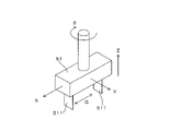
- FIG. 2 is a perspective view schematically showing a robot hand used for gripping a component in the component gripping system of FIG. 1
- FIG. 2 is a block diagram showing an example of an electrical configuration of a control device
- FIG. 2 is a flow chart showing an example of bin picking performed by the component gripping system of FIG. 1
- 4B is a flowchart showing an example of patch image processing performed in the bin picking of FIG. 4A
- 4B is a flowchart illustrating an example of grasp inference performed in the bin picking of FIG. 4A.
- FIG. 4C is a flowchart showing an example of determination of a gripping target part executed in the gripping inference of FIG.
- FIG. 4C is a diagram schematically showing operations performed in the patch image processing of FIG. 4B;
- FIG. 4C is a diagram schematically showing operations performed in the patch image processing of FIG. 4B;
- FIG. 4C is a diagram schematically showing operations performed in the patch image processing of FIG. 4B;
- FIG. 4C is a diagram schematically showing operations performed in the patch image processing of FIG. 4B;
- FIG. 4C is a diagram schematically showing operations performed in the patch image processing of FIG. 4B;
- FIG. 4D is a diagram schematically showing actions performed in the grasping inference of FIG. 4C;
- FIG. 4D is a diagram schematically showing actions performed in the grasping inference of FIG. 4C;
- FIG. 4C is a diagram schematically showing actions performed in the grasping inference of FIG. 4C;
- FIG. 4D is a diagram schematically showing actions performed in the grasping inference of FIG. 4C;
- FIG. 4D is a diagram schematically showing actions performed in the grasping inference of FIG. 4C;
- 4 is a flow chart showing an example of a method of collecting learning data for a registration neural network;
- FIG. 4 is a diagram schematically showing an example of a position determination mask generated from patch images;
- FIG. 8B is an example of a flowchart for training an alignment neural network on the training data collected in FIG. 8A.
- FIG. 10 is a diagram schematically showing an example in which use of a mask is advantageous for calculation of a loss function;
- An example of a flow chart for causing a grasp classification neural network to perform learning An example of a flow chart for causing a grasp classification neural network to perform learning.
- An example of a flow chart for causing a grasp classification neural network to perform learning. 6 is a flowchart showing an example of a re-learning method for a grasp classification neural network of a grasp classification network unit; A modification of the grasp classification neural network of the grasp classification network unit.
- FIG. 1 is a plan view schematically showing an example of a component gripping system according to the present invention
- FIG. 2 is a perspective view schematically showing a robot hand used for gripping components in the component gripping system of FIG.
- the horizontal X direction, the horizontal Y direction orthogonal to the X direction, and the vertical Z direction are indicated as appropriate. These X, Y and Z directions constitute a global coordinate system.
- the component gripping system 1 includes a control device 3 and a work robot 5 , and the work robot 5 performs work (bin picking) based on control by the control device 3 .
- a parts bin 91 and a kitting tray 92 are arranged in the work space of the work robot 5 .
- the parts bin 91 has a plurality of storage compartments 911 for storing parts, and each storage compartment 911 stores a large number of parts.
- the kitting tray 92 has a plurality of partitioned storages 921 for storing components, and each partitioned storage 921 holds a predetermined number of components. Then, the working robot 5 grips the parts from the partitioned storage 911 of the parts bin 91 (bin picking) and transfers them to the partitioned storage 921 of the kitting tray 92 .
- a trash can 93 is arranged between the parts bin 91 and the kitting tray 92, and the working robot 5 discards the defective parts in the trash can 93 when a defective part is detected.
- the working robot 5 is a scalar robot having a robot hand 51 provided at its tip. and disposal of the parts to the trash box 93 are executed.
- the robot hand 51 has degrees of freedom in the X, Y, Z and .theta. directions.
- the ⁇ direction is the direction of rotation about a rotation axis parallel to the Z direction.
- the robot hand 51 also has two claws 511 arranged in the gripping direction G, and each claw 511 has a flat plate shape perpendicular to the gripping direction G.
- the robot hand 51 can expand/reduce the distance between the two claws 511 in the gripping direction G, and grips the part by sandwiching the part in the gripping direction G with these claws 511 .
- the gripping direction G is parallel to the X direction in FIG. 2, the gripping direction G can be inclined with respect to the X direction depending on the position of the robot hand 51 in the ⁇ direction.
- the component gripping system 1 includes two cameras 81 and 83 and a mass meter 85.
- the camera 81 is a plan view camera that captures an image of a large number of parts accumulated in the partition storage 911 of the parts bin 91 from the Z direction (upward), and faces the working space of the working robot 5 from the Z direction.
- This camera 81 captures a grayscale image (two-dimensional image) that indicates the imaging target (component) in luminance and a depth image (three-dimensional image) that indicates the distance to the imaging target.
- a phase shift method or a stereo matching method can be used as a specific method of acquiring a depth image.
- the camera 83 is a side-view camera that takes an image of the component gripped by the robot hand 51 from the Y direction, and is attached horizontally to the base of the robot hand 51 .
- This camera 83 captures a grayscale image (two-dimensional image) that indicates an imaging target (component) with luminance.
- the mass meter 85 measures the mass of the parts placed in the compartment storage 921 of the kitting tray 92 .
- FIG. 3 is a block diagram showing an example of the electrical configuration of the control device.
- the control device 3 is, for example, a personal computer provided with an arithmetic unit 31, a storage unit 35 and a UI (User Interface) 39.
- the calculation unit 31 is a processor including, for example, a CPU (Central Processing Unit), and has a main control unit 311 and an image processing unit 4 .
- the main control unit 311 and the image processing unit 4 are developed in the calculation unit 31 by executing a predetermined program.
- the main control unit 311 controls hardware such as the robot hand 51, the cameras 81 and 83, and the mass meter 85 described above, and the image processing unit 4 recognizes a component to be gripped by the robot hand 51. Perform image processing.
- the image processing section 4 has an image synthesizing section 41 , a patch image generating section 43 , an alignment network section 45 and a grip classification network section 47 . These functions are described in detail below.
- the storage unit 35 is a storage device such as a HDD (Hard Disk Drive) or SSD (Solid State Drive). memorize
- the UI 39 has input devices such as a keyboard and a mouse, and output devices such as a display. It displays an image according to the command on the display.
- FIG. 4A is a flow chart showing an example of bin picking performed by the component gripping system of FIG. 1
- FIG. 4B is a flow chart showing an example of patch image processing performed in the bin picking of FIG. 4A
- FIG. 4D is a flow chart showing an example of grip inference performed in the bin picking of FIG. 4A
- FIG. 4D is a flow chart showing an example of determination of a grip target part performed in the grip inference of FIG. 4C.
- step S101 of bin picking in FIG. 4A the camera 81 captures a plan view image of a large number of parts piled up in the partitioned storage 911 of the parts bin 91 .
- the grayscale image Ig and the depth image Id are captured as described above.
- the main control unit 311 transfers these images Id and Ig acquired from the camera 81 to the image synthesizing unit 41 of the image processing unit 4, and the image synthesizing unit 41 executes patch image processing (step S102).
- 5A to 5E are diagrams schematically showing operations performed in the patch image processing of FIG. 4B.
- the image synthesizing unit 41 In step S201 of the patch image processing in FIG. 4B, the image synthesizing unit 41 generates a synthetic image Ic (FIG. 5C) by synthesizing the grayscale image Ig (FIG. 5A) and the depth image Id (FIG. 5B).
- the grayscale image Ig is composed of a plurality of pixels PX arranged two-dimensionally in the X direction and the Y direction. is.
- a notation for specifying one pixel PX is used by a combination (m, n) of "m” indicating the row number and "n” indicating the column number, and the pixel PX ( m,n) has luminance Vg(m,n). Note that the brightness Vg(m, n) has a larger value as the corresponding portion becomes brighter.
- the depth image Id is image data composed of a plurality of pixels PX, similar to the grayscale image Ig, and indicating the depth (distance) of the pixels PX for each of the plurality of pixels PX. Similar notation is used in FIG. 5B as in FIG. 5A, and the pixel PX(m,n) of the depth image Id has the depth Vd(m,n). Note that the depth Vd(m, n) has a larger value as the depth of the corresponding portion is shallower (in other words, as the position of the opposing portion is higher).
- the composite image Ic is image data that is composed of a plurality of pixels PX, similar to the grayscale image Ig, and indicates a composite value Vc of the pixels PX for each of the plurality of pixels PX.
- the same notation as in FIG. 5A is also used in FIG. 5C, and the pixel PX(m,n) of the composite image Ic has the composite value Vc(m,n).
- the brightness Vg normalized by the maximum brightness is multiplied by the depth Vd (weight).
- the normalization is not essential, and the combined value Vc may be calculated by multiplying the brightness Vg as it is by the depth Vd (weight).
- the composite value Vc should be determined so as to depend on both the brightness Vg and the depth Vd.
- FIG. 5D shows experimental results of generating a composite image Ic from the grayscale image Ig and the depth image Id.
- the grayscale image Ig (before filtering) is two-dimensional image data obtained by the camera 81, and the grayscale image Ig (after filtering) is obtained by filtering predetermined components (high frequency components) of the two-dimensional image data obtained by the camera 81. 2D image data removed by Also, the depth image Id (before filtering) is three-dimensional image data acquired by the camera 81, and the depth image Id (before filtering) is the three-dimensional image data acquired by the camera 81 by filtering a predetermined component (high frequency component).
- the synthesized image Ic is a depth-weighted grayscale image obtained by synthesizing the filtered grayscale image Ig and the depth image Id according to the above equation.
- range elliptical range
- Composite image Ic the grayscale image Ig (after filtering).
- the part that had been attached does not appear in the composite image Ic. This is because the part in question has a deep depth (in other words, it has a low height) and the brightness Vg of the part in question is given a small weight.
- the combination of the grayscale image Ig and the depth image Id has the effect of highlighting the components at high positions.
- the filter used in FIG. 5D is not essential, and similar effects can be obtained even if it is omitted as appropriate.
- the composite image Ic generated in step S201 of FIG. 4B is output from the image composition unit 41 to the patch image generation unit 43, and the patch image generation unit 43 executes the image processing of steps S202 to S204 on the composite image Ic. do.
- the specific content of this image processing is illustrated in FIG. 5E.
- the binary composite image Ic is obtained by binarizing the composite image Ic with a predetermined threshold value. In this binary composite image Ic, a closed region having high brightness (white) appears corresponding to the part.
- the patch image generation unit 43 performs labeling in which different labels (numbers) are associated with the components P (closed regions Rc) of the binary composite image Ic.
- a clipping range Rc for clipping an image including the part P from the binary composite image Ic is set.
- the cutout range Rc is set so as to represent the position of the robot hand 51 when the part P is gripped.
- This cutout range Rc corresponds to a gripping target range (gripping target range) of the robot hand 51, and the robot hand 51 can grip the part P existing in the cutout range Rc.
- the portion corresponding to the two claws 511 of the robot hand 51 facing the part P(2) from above for gripping the part P is the white part of the cutout range Rc.
- a solid line indicates a locus along which both ends of each claw 511 move is indicated by a white dashed line (parallel to the X direction).
- the claw 511 is parallel to the Y direction, and the rotation angle of the robot hand 51 in the ⁇ direction is zero degrees. That is, the setting of the cutout range Rc is performed in a state where the rotation angle of the robot hand 51 in the ⁇ direction is zero degrees.
- the patch image generation unit 43 acquires the image of the clipping range Rc from the binary composite image Ic as the patch image Ip (patch image generation). This patch image Ip is generated for each part P labeled in step S203.
- FIG. 4A when the patch image processing in step S102 is completed, the grip inference in step S103 (FIG. 4C) is executed.
- 6A-6C and 7 are diagrams schematically illustrating the actions performed in the grasp inference of FIG. 4C. 4C
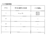
- patch image information (FIG. 6A) indicating a plurality of patch images Ip obtained by the patch image processing in step S102 is output from the image synthesizing unit 41 to the alignment network unit 45. be done.
- the patch image information indicates the patch image Ip, the label number of the patch image Ip, and the position of the cutout range Rc of the patch image Ip in association with each other.
- the shape of the cutout range Rc is the same for each patch image Ip, and the position (cutout position) of the cutout range Rc is specified by the X, Y, and ⁇ coordinates of the geometric center of gravity of the cutout range Rc.
- step S301 of FIG. 4C the alignment network unit 45 resets the count value for counting the labels of the plurality of patch images Ip indicated by the patch image information to zero (step S301). is incremented (step S302).
- step S303 the alignment network unit 45 determines whether the area of the object (white closed area) included in the patch image Ip with the current count value is appropriate. Specifically, each of the lower threshold and the upper threshold greater than the lower threshold is compared with the object area. Then, if the object area is smaller than the lower threshold or larger than the upper threshold, it is determined that the object area is inappropriate ("NO” in step S303), and the process returns to step S302. On the other hand, if the object area is greater than or equal to the lower threshold and less than or equal to the upper threshold, it is determined that the object area is appropriate ("YES" in step S303), and the process proceeds to step S304.
- step S304 the alignment network unit 45 calculates a correction amount for correcting the position of the clipping range Rc based on the patch image Ip with the current count value. That is, the alignment network section 45 has an alignment neural network, and this alignment neural network outputs correction amounts ( ⁇ x, ⁇ y, ⁇ ) of the clipping range Rc when the patch image Ip is input. The relationship between the patch image Ip and the correction amount of the cutout range Rc will be described with reference to FIG. 6C.
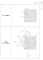
- the column of "Clipping range Rc" in FIG. 6C shows the clipping range Rc and the patch image Ip that has been clipped from the clipping range Rc.
- a corrected cropping range Rcc corrected according to the amounts ( ⁇ x, ⁇ y, ⁇ ) is superimposed on these.
- the cutout range Rc and the corrected cutout range Rcc have the same shape, and each of the following operations: Parallel movement in the X direction by the correction distance ⁇ x... X direction parallel operation ⁇ Parallel movement in the Y direction by the correction distance ⁇ y...Y direction Parallel operation/rotational movement in the ⁇ direction by a correction angle ⁇
- the cutout range Rc in which the ⁇ direction rotation operation is performed matches the corrected cutout range Rcc.
- the positional deviation between the center of the corrected cutout range Rcc and the part P is improved.
- the correction of the cutout range Rc is a correction for improving the positional deviation between the cutout range Rc and the part P, more specifically, a correction for converting the cutout range Rc into a corrected cutout range Rcc so that the part P is centered.
- the alignment neural network of the alignment network unit 45 corrects the clipping range Rc of the patch image Ip for the input of the patch image Ip to calculate the corrected clipping range Rcc by the correction amount ( ⁇ x, ⁇ y , ⁇ ).
- the calculation for correcting the clipping range Rc by the correction amount and converting it to the corrected clipping range Rcc is performed by using a rotation matrix that rotates ⁇ in the ⁇ direction, and a parallel translation of ⁇ y in the Y direction while translating ⁇ x in the X direction. can be done by multiplying it with the translation matrix Also, if it is necessary to consider enlargement/reduction of the image, the scaling matrix may be further multiplied.
- step S305 the alignment network unit 45 corrects the cutout range Rc based on the correction amount output by the alignment neural network, thereby creating a corrected cutout range Rcc, and correcting the cutout range Rcc from the binary composite image Ic.
- An image of the range Rcc is acquired as a correction patch image Ipc (correction patch image generation).
- steps S302 to S305 are repeated until steps S302 to S305 are completed for all labels (in other words, all patch images Ip) included in the patch image information (until "YES" in step S306).
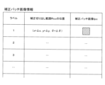
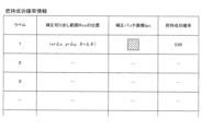
- correction patch image information (FIG. 6B) indicating a plurality of correction patch images Ipc is output from the alignment network unit 45 to the grip classification network unit 47.
- FIG. 6B the correction patch image information indicates the correction patch image Ipc, the label number of the correction patch image Ipc, and the position of the correction cutout range Rcc of the correction patch image Ipc in association with each other.
- the shape of the corrected cutout range Rcc is the same for each corrected patch image Ipc, and the position (cutout position) of the corrected cutout range Rcc is specified by the X, Y, and ⁇ coordinates of the geometric center of gravity of the corrected cutout range Rcc.
- step S307 the gripping classification network unit 47 calculates the gripping success probability for each of the plurality of correction patch images Ipc indicated in the correction patch image information. Specifically, with the robot hand 51 positioned at the position (x + ⁇ x, y + ⁇ y, ⁇ + ⁇ ) of the correction cutout range Rcc, an attempt was made to grasp the part P indicated by the correction patch image Ipc cut out in the correction cutout range Rcc. A success probability (grasping success probability) in the case is calculated. That is, the grip classification network unit 47 has a grip classification neural network, and this grip classification neural network outputs the grip success probability corresponding to the corrected patch image Ipc when the corrected patch image Ipc is input. Thus, the gripping success probability information shown in FIG.
- the grasping success probability information includes the correction patch image Ip, the label number of the correction patch image Ipc, the position of the correction cut-out range Rcc of the correction patch image Ipc, and the correction patch image Ipc. It is shown in association with the gripping success probability. Although the gripping success probability is indicated by a value between 0 and 1 in the example of FIG. 7, it may be indicated by a percentage.
- step S ⁇ b>308 the main control unit 311 determines the part P to be gripped based on the gripping success probability information output from the gripping classification network unit 47 .
- each correction patch image Ipc of the gripping success probability information is sorted in descending order according to the gripping success probability (step S401). That is, the corrected patch image Ipc having a higher grasping success probability is sorted at a higher rank.
- correction patch images Ipc with the same gripping success probability are sorted in descending order according to the object area included in the correction patch images Ipc. That is, correction patch images Ipc having larger object areas are sorted higher.
- the sort order count value is reset to zero, and in step S404, the count value is incremented.
- step S405 it is determined whether the part P included in the correction patch image Ipc of the current count value is close to the end of the partition storage 911 (container) of the part bin 91. Specifically, if the distance between the position of the correction clipping range Rcc from which the correction patch image Ipc is clipped and the wall surface of the partition storage 911 is less than a predetermined value, it is close to the end of the container ("YES" in step S405). ”), and the process returns to step S404. On the other hand, if the distance is equal to or greater than the predetermined value, it is determined that the object is not close to the edge of the container ("NO" in step S405), and the process proceeds to step S406. In step S406, the correction patch image Ipc of the current count value is selected as one correction patch image Ipc indicating the part P to be gripped. Then, return to the flow chart of FIG. 4A.
- step S104 of FIG. 4A the robot hand 51 moves to the position indicated by the correction cutout range Rcc corresponding to the one correction patch image Ipc selected in step S103, and grips the part P indicated by the one correction patch image Ipc. do.
- step S105 the image of the part P gripped by the robot hand 51 is captured by the camera 83.
- step S106 the main control unit 311 detects the part P gripped by the robot hand 51 from the image captured by the camera 83. judge. Further, the main control unit 311 determines whether the number of the gripped parts P is one (step S107), and if not one ("NO" in step S107), the robot hand 51 The part P is returned to the partition storage 911 of the part bin 91 (step S108).
- step S107 When the number of gripped parts P is one ("YES" in step S107), the main control unit 311 determines whether the gripped part P is normal (step S109). ), if there is an abnormality such as the area indicating the part P being too small ("NO” in step S109), the robot hand 51 discards the part P in the trash box 93 (step S110).
- step S109 the main control unit 311 causes the robot hand 51 to place the part P in the compartment storage 921 of the kitting tray 92 (step S111). ). Subsequently, the main controller 311 measures the mass with the mass meter 85 (step S112), and determines whether the mass indicated by the mass meter 85 is appropriate (step S113). Specifically, it can be determined based on whether the mass corresponding to the part P placed on the kitting tray 92 has increased. Then, if the mass is not appropriate (“NO” in step S113), the main control unit 311 notifies the operator of the abnormality using the UI 39, and if the mass is appropriate (“NO” in step S113). YES"), the main control unit 311 returns to step S101.
- the alignment network unit 45 calculates correction amounts ( ⁇ x, ⁇ y, ⁇ ) for correcting the clipping range Rc based on the patch image Ip clipped from the clipping range Rc.
- the alignment network unit 45 uses the alignment neural network to calculate the correction amount of the clipping range Rc from the patch image Ip.
- a method of making the alignment neural network learn the relationship between the patch image Ip and the correction amount of the clipping range Rc will be described.
- FIG. 8A is a flow chart showing an example of a method of collecting learning data for a registration neural network.
- This flowchart is executed by the calculation unit 31 of the control device 3 .
- the computing unit 31 is configured with a simulator that executes bin picking in a component gripping system 1 that is virtually constructed by computation (hereinafter referred to as “virtual component gripping system 1” as appropriate).
- This simulator virtually executes the operation of the robot hand 51 gripping the part P from the partition storage 911 of the part bin 91 by computation based on physical parameters such as gravitational acceleration and friction coefficient.
- step S501 it is confirmed whether the number of data necessary for learning has been acquired. This required number can be preset, for example, by an operator. If the required number of data has been acquired ("YES" in step S501), the flowchart in FIG. 8A ends. ), the process proceeds to step S502.
- step S502 it is determined whether or not sufficient parts P are stored in the partition storage 911 of the part bin 91 arranged in the virtual part grasping system 1. Specifically, it can be determined based on whether the number of parts P is equal to or greater than a predetermined number. When the number of parts P in the partitioned storage 911 of the parts bin 91 is less than the predetermined number ("NO" in step S502), the number of parts P in the partitioned storage 911 of the parts bin 91 is reset. is increased to the initial value (step S503), and the process returns to step S501. On the other hand, if the number of parts P in the partitioned storage 911 of the parts bin 91 is equal to or greater than the predetermined number ("YES" in step S502), the process proceeds to step S504.
- step S504 a composite image Ic is generated in the virtual part grasping system 1 in the same manner as in the case of the real part grasping system 1 described above. Subsequently, this synthesized image Ic is binarized to generate a binary synthesized image Ic, and each component P included in this binary synthesized image Ic is labeled (step S505). . Then, a clipping range Rc is set for each labeled part P, and a patch image Ip is clipped (step S506).
- step S507 the count value for counting each patch image Ip is reset, and at step S508, the count value is incremented. Then, in the same manner as described above, it is determined whether the area of the object (white closed region) included in the patch image Ip with the current count value is appropriate (step S509). If the area of the object is inappropriate (“NO” in step S509), the process returns to step S508. If the area of the object is appropriate (“YES” in step S509), step S510 proceed to
- FIG. 8B is a diagram schematically showing an example of a position determination mask generated from patch images.
- This position determination mask Mp has a contour having the same shape as the patch image Ip (in other words, the cutout range Rc).
- a reference pattern Pr is arranged.
- the component reference pattern Pr is generated so as to have the number of pixels in each of the vertical and horizontal directions of the component P (in other words, white closed area) included in the patch image Ip.
- This position determination mask Mp is a model of an ideal patch image Ip in which the part P is positioned at the center. Then, the patch image Ip and the position determination mask Mp generated from the patch image Ip are associated and stored in the patch image list (step S511).
- Step S501 Steps S501 to S511 are repeated until the required number of data is acquired, in other words, until the number of pairs of the patch image Ip and the position determination mask Mp stored in the patch image list reaches the required number. executed.
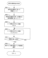
- FIG. 9A is an example of a flow chart for making the registration neural network learn the learning data collected in FIG. 8A. This flowchart is executed by the calculation unit 31 of the control device 3 . In step S601, it is determined whether the number of times of learning has reached a predetermined number. This predetermined number can be set in advance by the operator, for example.
- step S602 the unlearned patch image Ip selected from the patch image list is forward-propagated to the alignment neural network of the alignment network unit 45.
- the neural network of the alignment network unit 45 outputs the correction amount ( ⁇ x, ⁇ y, ⁇ ) corresponding to the patch image Ip.
- the alignment network unit 45 cuts out the binary composite image Ic (generated in step S505) within the corrected cutout range Rcc obtained by correcting the cutout range Rc by this correction amount, thereby generating the corrected patch image Ipc (step S603).
- step S604 the alignment network unit 45 superimposes the position determination mask Mp corresponding to the patch image Ip selected in step S602 and the correction patch image Ipc so that their outlines match each other, thereby forming the position determination mask Mp.
- a mean square error between the component reference pattern Pr and the component P included in the correction patch image Ipc is calculated as a loss function.
- step S605 the parameters of the alignment neural network are updated by backpropagating this loss function in the alignment neural network (error backpropagation).
- FIG. 9B is a diagram schematically showing an example in which the use of a mask is advantageous in calculating the loss function.
- the part P included in the correction patch image Ipc shown in FIG. 9B has a zigzag shape, and it is difficult to appropriately obtain the principal axis angle from the moment of the image of this part P. Therefore, the position determination mask Mp is used here from the viewpoint of handling parts P having various shapes.
- step S606 of the patch images Ip stored in the patch image list, the patch images Ip (test data) reserved in advance for testing and not used for learning are forward-propagated to the alignment neural network whose parameters have been updated. , the correction amount is calculated. Then, based on this correction amount, the loss function is calculated using the position determination mask Mp corresponding to the test data in the same manner as in steps S603 and S604.
- the calculation unit 31 stores the loss function calculated in step S606 each time step S606 is executed, and calculates the minimum value among the plurality of loss functions thus stored. Then, the calculation unit 31 checks whether the most recently calculated loss function has updated the minimum value. Especially in step S607, it is determined whether the minimum value has not been updated ten times in a row, that is, whether a loss function larger than the minimum value has been calculated. Then, if a loss function less than or equal to the minimum value has been calculated in the last 10 times ("NO" in step S607), the process returns to step S601. If calculated ("YES" in step S607), the flowchart of FIG. 9A ends. Note that the number of times is not limited to 10 times, and can be changed as appropriate.
- the grasping classification network unit 47 classifies the part P included in the correction patch image Ipc into the position indicated by the correction patch image Ipc.
- a gripping success probability when gripped by the robot hand 51 is calculated.
- the grip classification network unit 47 uses a grip classification neural network to calculate the grip success probability from the corrected patch image Ipc.
- Figs. 10A to 10C are an example of a flow chart for causing the grasp classification neural network to perform learning. This flowchart is executed by the calculation unit 31 of the control device 3 .
- a simulator for constructing the virtual part gripping system 1 is used in learning of the gripping classification neural network as in the learning of the alignment neural network described above.
- steps S701-S709 of FIG. 10A are similar to steps S501-S509 of FIG. 8A, except for the following points. That is, in step S701, it is determined whether or not the number of times of learning has reached a predetermined number, not the number of data acquisitions. This predetermined number can be set in advance by the operator, for example.
- step S710 when one patch image Ip having an appropriate object area is selected by executing steps S701 to S709, the alignment network unit 45 uses the alignment neural A correction amount corresponding to the patch image Ip is calculated using a network (step S710), and the patch image Ip and the correction amount are associated and stored in a correction amount list (step S711). Steps S708 to S711 are repeated until the count value reaches the maximum ("YES” in step S712), and pairs of patch images Ip and correction amounts are sequentially stored in the correction amount list. When the count value reaches the maximum (“YES” in step S712), the process proceeds to step S712 in FIG. 10B.
- step S712 the alignment network unit 45 corrects the clipping range Rc of the patch image Ip based on the correction amount to generate the corrected clipping range Rcc, and performs processing for generating the corrected patch image Ipc based on the corrected clipping range Rcc. , for each pair of the patch image Ip and the correction amount stored in the correction amount list. As a result, a plurality of correction patch images Ipc are generated.
- the specific procedure for generating the correction patch image Ipc is as described above.
- step S713 it is confirmed whether the number of data necessary for learning has been acquired. This required number can be preset, for example, by an operator. If the required number of data has already been acquired ("YES" in step S713), the process proceeds to step S717 (FIG. 10C), which will be described later. ), the process proceeds to step S714.
- step S714 one correction patch image Ipc is randomly selected (for example, based on the output of a random number generator) from among the plurality of correction patch images Ipc generated in step S712. Then, in step S715, in the virtual part gripping system 1, the robot hand 51 positioned at the position of the one correction patch image Ipc attempts to grip the part P included in the one correction patch image Ipc. The position of the correction patch image Ipc corresponds to the position of the correction cutout range Rcc obtained by cutting out the correction patch image Ipc. Then, the success/failure result of the gripping trial (1 for success, 0 for failure) is stored in the success/failure result list in association with the correction patch image Ipc (step S716). Return to step S701.
- step S713 if it is determined that the required number of data has been acquired (YES) in step S713, the process proceeds to step S717 in FIG. 10C as described above.
- step S717 a horizontally inverted corrected patch image Ipc obtained by horizontally reversing the corrected patch image Ipc, a vertically reversed corrected patch image Ipc obtained by vertically reversing the corrected patch image Ipc, and a horizontally reversed corrected patch image Ipc are horizontally and vertically reversed.
- a vertically-horizontally reversed corrected patch image Ipc is generated.
- three types of images ie, the horizontally-reversed corrected patch image Ipc, the vertically-reversed corrected patch image Ipc, and the vertically-horizontally reversed corrected patch image Ipc are prepared for each corrected patch image Ipc in the success/failure result list. That is, a plurality of correction patch images Ipc are prepared in a number that is three times the number of correction patch images Ipc stored in the success/failure result list.
- each of the plurality of correction patch images Ipc generated in step S717 is forward-propagated in the grasp classification neural network of the grasp classification network unit 47, and the grasp success probability is calculated for each correction patch image Ipc.
- the average value of the grasping success probability of each of the horizontal-reversed corrected patch image Ipc, the vertically-reversed corrected patch image Ipc, and the vertically-horizontally reversed corrected patch image Ipc generated from the same corrected patch image Ipc is calculated.
- the average value of the gripping success probability is calculated for each correction patch image Ipc stored in the success/failure result list.
- step S720 one of "0", “1” and “2” is generated by a random number generator. Then, when “0” is obtained in the random number generation, one correction patch image Ipc is randomly selected from among the correction patch images Ipc for which the gripping success probability has been calculated in step S719 (step S721). When “1” is obtained by random number generation, one correction patch image Ipc whose grip success probability is closest to "0.5” (in other words, 50%) is selected from among the correction patch images Ipc. If it is selected (step S722) and "2" is obtained by random number generation, one correction patch image Ipc with the highest gripping success probability is selected from among the correction patch images Ipc (step S723).
- step S724 in the virtual part gripping system 1, the robot hand 51 positioned at the position of the one correction patch image Ipc attempts to grip the part P indicated by the one correction patch image Ipc. Then, a loss function is calculated based on the success or failure result of component gripping (1 for success, 0 for failure) and the average gripping success probability calculated for the one correction patch image Ipc in step S719. be. Various well-known functions such as cross-entropy error can be used as the loss function.
- the calculation unit 31 stores the loss function calculated in step S725 each time step S725 is executed, and calculates the minimum value among the plurality of loss functions thus stored. Then, the calculation unit 31 checks whether the most recently calculated loss function has updated the minimum value. In particular, in step S726, it is determined whether the minimum value has not been updated ten times in a row, that is, whether a loss function greater than the minimum value has been calculated. If a loss function less than or equal to the minimum value has been calculated in the last 10 times ("NO" in step S726), the result of gripping success or failure in step S724 is associated with one correction patch image Ipc. are stored in the success/failure result list (step S727).
- step S728 the loss function calculated in step S725 is back-propagated in the gripping classification neural network (error backpropagation) to update the parameters of the gripping classification neural network.
- step S726 if a loss function larger than the minimum value is calculated ten times in a row ("NO"), the process returns to step S701 in FIG. 10A. Note that the number of times is not limited to 10 times, and can be changed as appropriate.
- a correction patch image Ipc including a part P at a position where one part P can be gripped with a high probability of success can be obtained based on the correction amounts ( ⁇ x, ⁇ y, ⁇ ) obtained from the patch image Ip. Therefore, there is no need to calculate the gripping success probability for each of the plurality of patch images Ip corresponding to the case where the robot hand 51 grips one part P at a plurality of positions (especially rotational positions) different from each other. In this way, it is possible to reduce the computational load required to calculate the grasping success probability when the robot hand 51 tries to grasp the part P.
- the alignment network unit 45 uses the positional difference between the position determination mask Mp indicating the appropriate position of the part P in the cutout range Rc and the part P included in the patch image Ip as teacher data.
- the relationship between the image Ip and the correction amount ( ⁇ x, ⁇ y, ⁇ ) is learned (steps S601 to S607).
- the alignment network unit 45 also generates a patch image Ip based on the shape of the part P included in the patch image Ip (step S510). With such a configuration, learning can be performed using an appropriate position determination mask Mp adapted to the shape of the part P.
- FIG. 5
- the alignment network unit 45 back-propagates the mean square error of the position between the part P included in the patch image Ip and the position determination mask Mp (the part reference pattern Pr thereof) as a loss function to obtain the patch image Ip.
- Learning is executed to update the parameters that define the relationship with the correction amounts ( ⁇ x, ⁇ y, ⁇ ) (steps S604 and S605).
- the alignment network unit 45 repeats learning while changing the patch image Ip (steps S601 to S607). With such a configuration, highly accurate learning results can be obtained.
- the alignment network unit 45 terminates learning when the number of repetitions of learning reaches a predetermined number (step S601). Also, the registration network unit 45 terminates learning according to the result of determining the state of convergence of the loss function in step S607. Specifically, when the minimum value of the loss function is not updated a predetermined number of times (10 times) in succession, it is determined that the loss function has converged, and learning ends.
- the main controller 311 image acquisition unit
- the main controller 311 acquires a grayscale image Ig (brightness image) representing the plurality of parts P and the depth image Id representing the plurality of parts P
- the grayscale image acquired by the main controller 311 An image synthesizing unit 41 is provided that generates a synthesized image Ic by synthesizing the scale image Ig and the depth image Id.
- the patch image generation unit 43 generates the patch image Ip from the composite image Ic and inputs it to the alignment network unit 45 . That is, the synthetic image Ic is generated by synthesizing the grayscale image Ig and the depth image Id respectively representing the plurality of parts P.
- the shape of the component P at a relatively high position among the plurality of components P tends to remain, which is advantageous for recognizing such a component (in other words, a component with a high probability of successful gripping).
- the component gripping system 1 corresponds to an example of the "component gripping system” of the present invention
- the control device 3 corresponds to an example of the "image processing device” of the present invention
- the main control unit 311 corresponds to an example of the "image acquiring section” of the present invention
- the image synthesizing section 41 corresponds to an example of the “image synthesizing section” of the present invention
- the patch image generating section 43 corresponds to the "patch image generating section” of the present invention.
- the alignment network unit 45 corresponds to an example of the "alignment unit” of the present invention
- the alignment network unit 45 corresponds to an example of the "corrected image generation unit” of the present invention
- the grip classification network unit 47 corresponds to an example of the "holding and classifying section” of the present invention
- the robot hand 51 corresponds to an example of the "robot hand” of the present invention
- the partitioned storage 911 of the parts bin 91 corresponds to an example of the "container” of the present invention.
- the composite image Ic corresponds to an example of the "storage component image” of the present invention
- the depth image Id corresponds to an example of the "depth image” of the present invention
- the grayscale image Ig corresponds to the "brightness image” of the present invention.
- the patch image Ip corresponds to an example of the "first patch image” of the invention
- the correction patch image Ipc corresponds to an example of the "second patch image” of the invention
- the position determination mask Mp corresponds to an example of the "second patch image” of the invention.
- the part P corresponds to an example of the "part” of the present invention
- the cutout range Rc corresponds to an example of the "target range” of the present invention
- the correction amount ( ⁇ x , ⁇ y, ⁇ ) correspond to an example of the “correction amount” of the present invention.
- step S105 the component P gripped by the robot hand 51 may be imaged by the camera 83 from different directions to acquire a plurality of side view images.
- These side-view images can be obtained, for example, by imaging the component P while rotating the robot hand 51 that grips the component P in the ⁇ direction.
- confirmation of the number of parts P in step S107 and confirmation of abnormalities (too small area) of parts P in step S109 can be performed from a plurality of directions.
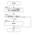
- FIG. 11 is a flow chart showing an example of the re-learning method of the grip classification neural network of the grip classification network unit. This flowchart is executed by the main control unit 311, for example, when the planned bin picking is finished.
- step S801 the main control unit 311 detects an abnormality based on the side-view image (“NO” in steps S107 and S108) or an abnormality based on mass measurement (“NO” in step S113) in the bin picking performed in the past. Check the detected history. Then, if the number of times an abnormality is detected is equal to or greater than a predetermined number ("YES" in step S802), re-learning of the gripping classification neural network of the gripping classification network unit 47 is executed (step S803). In this re-learning, the correction patch image Ipc indicating the part P in which the abnormality was detected and the gripping success/failure result (that is, failure) are used as teaching data.
- an error function is calculated based on the gripping success/failure probability obtained by forward propagation of the corrected patch image Ipc through the gripping classification neural network and the gripping success/failure result (failure), and the error function is calculated in the gripping classification neural network.
- Backpropagation updates the parameters of the grasp classification neural network (relearning).
- the gripping classification neural network is caused to re-learn based on the results of acquiring the gripping state information (side-view image, mass) for the part P gripped by the robot hand 51 .
- the gripping classification neural network is re-learned according to the actual success or failure of gripping the selected part P based on the gripping success probability obtained for the correction patch image Ipc, and the gripping success probability by the gripping classification neural network is obtained.
- Fig. 12 is a modified example of the grip classification neural network of the grip classification network unit.
- a multilayer convolutional neural network 472 and a fully connected layer 473 are arranged in series.
- a spatial attention module 474 and a channel attention module 475 are provided on the output side of each convolutional neural network 472, and the feature amount map output from the convolutional neural network 472 is used for the spatial attention module 474 and the channel attention module.
- the attention mask Ma that the spatial attention module 474 adds to the feature amount map has two regions of interest Pg and Pp passing through the center position of the corrected patch image Ipc (in other words, the corrected cropping range Rcc). That is, in the attention mask Ma, the weights of the attention areas Pg and Pp are higher than the weights of the other areas, and these weights are added to the feature amount map.
- the attention area Pg is parallel to the gripping direction G
- the attention area Pp is orthogonal to the gripping direction G.
- the attention area Pp is parallel to the long axis direction of the part P.
- this attention mask Ma is divided into an attention area Pp corresponding to the ideal position of the part P in the correction patch image Ipc and an attention area Pg corresponding to the path along which the claw 511 of the robot hand 51 approaches the part P. Focus on it.
- the attention mask Ma having such a configuration is added to the feature map output from the convolutional neural network 472 to weight the feature map. Therefore, the angle of the long axis direction of the part P with respect to the gripping direction G and the status of the movement path of the robot hand 51 gripping the part P (presence or absence of other parts) can be accurately reflected in the determination by the gripping classification neural network. can be done.
- the gripping classification network unit 47 uses the convolutional neural network 472 to calculate the gripping success probability from the corrected patch image Ipc. This makes it possible to accurately calculate the gripping success probability from the corrected patch image Ipc.
- the grasp classification network unit 47 weights the feature map output from the convolutional neural network 472 by adding an attention mask Ma to the feature map.
- the attention mask Ma includes a region of interest Pg that extends in the gripping direction G in which the robot hand 51 grips the part P and passes through the center of the correction patch image Ipc, and a region of interest Pg that extends perpendicularly to the gripping direction G and passes through the center of the correction patch image Ipc. This indicates that attention is paid to the attention area Pp. This makes it possible to accurately calculate the gripping success probability while taking into account the influence of the orientation of the component P and the surrounding conditions of the component P (the presence or absence of other components P) on gripping by the robot hand 51. .
- the method of generating the composite image Ic is not limited to the example using the above formula, and the composite value Vc of the composite image Ic is calculated by weighting the brightness Vg of the grayscale image Ig by the depth Vd of the depth image Id. You may generate the synthetic image Ic by other formulas.
- the grayscale image Ig and the depth image Id are synthesized to generate the synthesized image Ic.
- the reversed grayscale image Ig luminance image
- the composite image Ic when gripping a component P having a black-plated surface, it is preferable to generate the composite image Ic using the inverted grayscale image Ig.
- the patch image Ip may be cut out from the composite image Ic without executing the binarization.
- the corrected patch image Ipc may be cut out from the composite image Ic without executing the binarization.
- the cutout range Rc can be set so that the geometric center of gravity of the cutout range Rc coincides with the geometric center of gravity of the part P.
- the cutout range Rc may be set so as to include the target part P.
- the specific configuration of the robot hand 51 is not limited to the above example.
- the number of claws 511 of the robot hand 51 is not limited to two, and may be three or more.
- a robot hand 51 that attracts by negative pressure or magnetic force can also be used.
- the clipping range Rc can be set in the range to be gripped by the robot hand 51, and the patch image Ip can be clipped from the clipping range Rc.
- the patch image Ip is created from the synthesized image Ic obtained by synthesizing the grayscale image Ig and the depth image Id.
- the patch image Ip is created from one of the grayscale image Ig and the depth image Id, and the correction amount ( ⁇ x, ⁇ y, ⁇ ) is calculated by the registration network unit 45 based on the patch image Ip. Calculation of the gripping success probability by
Landscapes
- Engineering & Computer Science (AREA)
- Robotics (AREA)
- Mechanical Engineering (AREA)
- Computer Vision & Pattern Recognition (AREA)
- Physics & Mathematics (AREA)
- General Physics & Mathematics (AREA)
- Theoretical Computer Science (AREA)
- Human Computer Interaction (AREA)
- Manipulator (AREA)
- Image Processing (AREA)
Abstract
Selon l'invention, lorsqu'une image pièce (Ip) (une première image pièce) obtenue en découpant une image d'une plage de découpe (Rc) (une plage cible) définie pour un composant (P) est entrée dans une unité réseau d'alignement (45), des quantités de correction (Δx, Δy, Δθ) pour corriger la position de la plage de découpe (Rc) pour ledit composant (P) inclus dans l'image pièce (Ip) sont délivrées en sortie (étape S304) par l'unité réseau d'alignement (45). Une image pièce corrigée (Ipc) (une seconde image pièce) qui comprend ledit composant (P) et est obtenue en découpant une image composite (Ic) (une image de composant stockée) à partir d'une image d'une plage de découpe corrigée (Rcc) obtenue en corrigeant la plage de découpe (Rc) par les quantités de correction (Δx, Δy, Δθ) est ensuite générée (étape S305), et une probabilité de réussite de préhension concernant l'image pièce corrigée (Ipc) est calculée (étape S307).
Priority Applications (3)
| Application Number | Priority Date | Filing Date | Title |
|---|---|---|---|
| CN202180102303.2A CN117999153A (zh) | 2021-09-15 | 2021-09-15 | 图像处理装置、元件把持系统、图像处理方法和元件把持方法 |
| PCT/JP2021/033962 WO2023042306A1 (fr) | 2021-09-15 | 2021-09-15 | Dispositif de traitement d'image, système de préhension de composant, procédé de traitement d'image et procédé de préhension de composant |
| JP2023548005A JPWO2023042306A1 (fr) | 2021-09-15 | 2021-09-15 |
Applications Claiming Priority (1)
| Application Number | Priority Date | Filing Date | Title |
|---|---|---|---|
| PCT/JP2021/033962 WO2023042306A1 (fr) | 2021-09-15 | 2021-09-15 | Dispositif de traitement d'image, système de préhension de composant, procédé de traitement d'image et procédé de préhension de composant |
Publications (1)
| Publication Number | Publication Date |
|---|---|
| WO2023042306A1 true WO2023042306A1 (fr) | 2023-03-23 |
Family
ID=85602545
Family Applications (1)
| Application Number | Title | Priority Date | Filing Date |
|---|---|---|---|
| PCT/JP2021/033962 WO2023042306A1 (fr) | 2021-09-15 | 2021-09-15 | Dispositif de traitement d'image, système de préhension de composant, procédé de traitement d'image et procédé de préhension de composant |
Country Status (3)
| Country | Link |
|---|---|
| JP (1) | JPWO2023042306A1 (fr) |
| CN (1) | CN117999153A (fr) |
| WO (1) | WO2023042306A1 (fr) |
Citations (6)
| Publication number | Priority date | Publication date | Assignee | Title |
|---|---|---|---|---|
| US20150235351A1 (en) * | 2012-09-18 | 2015-08-20 | Iee International Electronics & Engineering S.A. | Depth image enhancement method |
| JP2017030135A (ja) * | 2015-07-31 | 2017-02-09 | ファナック株式会社 | ワークの取り出し動作を学習する機械学習装置、ロボットシステムおよび機械学習方法 |
| JP2017185577A (ja) * | 2016-04-04 | 2017-10-12 | ファナック株式会社 | シミュレーション結果を利用して学習を行う機械学習装置,機械システム,製造システムおよび機械学習方法 |
| JP2017185578A (ja) * | 2016-04-05 | 2017-10-12 | 株式会社リコー | 物体把持装置及び把持制御プログラム |
| JP2020015141A (ja) * | 2018-07-26 | 2020-01-30 | Ntn株式会社 | 把持装置 |
| JP2020532440A (ja) * | 2017-09-01 | 2020-11-12 | カリフォルニア大学The Regents of the University of California | オブジェクトをロバストに把持し、ターゲティングするためのロボットシステムおよび方法 |
-
2021
- 2021-09-15 WO PCT/JP2021/033962 patent/WO2023042306A1/fr active Application Filing
- 2021-09-15 JP JP2023548005A patent/JPWO2023042306A1/ja active Pending
- 2021-09-15 CN CN202180102303.2A patent/CN117999153A/zh active Pending
Patent Citations (6)
| Publication number | Priority date | Publication date | Assignee | Title |
|---|---|---|---|---|
| US20150235351A1 (en) * | 2012-09-18 | 2015-08-20 | Iee International Electronics & Engineering S.A. | Depth image enhancement method |
| JP2017030135A (ja) * | 2015-07-31 | 2017-02-09 | ファナック株式会社 | ワークの取り出し動作を学習する機械学習装置、ロボットシステムおよび機械学習方法 |
| JP2017185577A (ja) * | 2016-04-04 | 2017-10-12 | ファナック株式会社 | シミュレーション結果を利用して学習を行う機械学習装置,機械システム,製造システムおよび機械学習方法 |
| JP2017185578A (ja) * | 2016-04-05 | 2017-10-12 | 株式会社リコー | 物体把持装置及び把持制御プログラム |
| JP2020532440A (ja) * | 2017-09-01 | 2020-11-12 | カリフォルニア大学The Regents of the University of California | オブジェクトをロバストに把持し、ターゲティングするためのロボットシステムおよび方法 |
| JP2020015141A (ja) * | 2018-07-26 | 2020-01-30 | Ntn株式会社 | 把持装置 |
Non-Patent Citations (1)
| Title |
|---|
| MATSAMURA, RYO; HARADA, KENSUKE; DOMAE, YUKIYASU: "2P1-A02 Learning Based Randomized Bin-picking Trained with Physics Simulator", THE JAPANESE SOCIETY OF MECHANICAL ENGINEERS, JAPAN SOCIETY OF MECHANICAL ENGINEERS; ROBOTICS AND MECHATRONICS DIVISION, JP, 1 January 2017 (2017-01-01) - 13 May 2017 (2017-05-13), JP , pages 2P1 - 2P1-A02(4), XP009544505, ISSN: 2424-3124, DOI: 10.1299/jsmermd.2017.2P1-A02 * |
Also Published As
| Publication number | Publication date |
|---|---|
| CN117999153A (zh) | 2024-05-07 |
| JPWO2023042306A1 (fr) | 2023-03-23 |
Similar Documents
| Publication | Publication Date | Title |
|---|---|---|
| CN112476434B (zh) | 一种基于协作机器人的视觉3d取放方法及系统 | |
| JP6608890B2 (ja) | 機械学習装置、ロボットシステム及び機械学習方法 | |
| CN112297013B (zh) | 一种基于数字孪生和深度神经网络的机器人智能抓取方法 | |
| JP6671694B1 (ja) | 機械学習装置、機械学習システム、データ処理システム及び機械学習方法 | |
| CN108748149B (zh) | 一种复杂环境下基于深度学习的无标定机械臂抓取方法 | |
| CN111331607B (zh) | 一种基于机械臂的自主抓取与码垛方法及系统 | |
| JPWO2009028489A1 (ja) | 物体検出方法と物体検出装置およびロボットシステム | |
| JP7481427B2 (ja) | 取り出しシステム及び方法 | |
| CN111360862A (zh) | 一种基于卷积神经网络的生成最佳抓取位姿的方法 | |
| WO2021085561A1 (fr) | Procédé de génération de données d'apprentissage | |
| CN113119108B (zh) | 一种二指机械臂抓取方法、系统、装置及存储介质 | |
| US9098913B2 (en) | Prediction of successful grasps by end of arm tooling | |
| CN115446827A (zh) | 使用模块化神经网络的抓取学习 | |
| CN115456139A (zh) | 用于学习高维机器人任务的网络模块化 | |
| WO2023042306A1 (fr) | Dispositif de traitement d'image, système de préhension de composant, procédé de traitement d'image et procédé de préhension de composant | |
| WO2023042307A1 (fr) | Dispositif de traitement d'images, système de préhension d'outil, procédé de traitement d'images et procédé de préhension d'outil | |
| US20210241476A1 (en) | Training a pose detection algorithm, and deriving an object pose using a trained pose detection algorithm | |
| CN113496524A (zh) | 通过深度学习和矢量场估计的特征检测 | |
| CN109816728B (zh) | 基于生成查询网络的机械臂抓取点定位检测的方法 | |
| CN113436293B (zh) | 一种基于条件生成式对抗网络的智能抓取图像生成方法 | |
| Suzui et al. | Toward 6 dof object pose estimation with minimum dataset | |
| Kumra et al. | Learning multi-step robotic manipulation policies from visual observation of scene and q-value predictions of previous action | |
| JP2024032055A (ja) | 対象物の位置姿勢を認識する方法、及び、コンピュータープログラム | |
| Prew et al. | Evaluating Gaussian Grasp Maps for Generative Grasping Models | |
| JP7446615B2 (ja) | データセット生成装置、生成方法、プログラム、システム、機械学習装置、物体認識装置、及びピッキングシステム |
Legal Events
| Date | Code | Title | Description |
|---|---|---|---|
| 121 | Ep: the epo has been informed by wipo that ep was designated in this application |
Ref document number: 21957488 Country of ref document: EP Kind code of ref document: A1 |
|
| WWE | Wipo information: entry into national phase |
Ref document number: 2023548005 Country of ref document: JP |