WO2023038034A1 - 炭化水素製造設備、炭化水素製造システム、炭化水素製造装置の制御器及び炭化水素を製造する方法 - Google Patents
炭化水素製造設備、炭化水素製造システム、炭化水素製造装置の制御器及び炭化水素を製造する方法 Download PDFInfo
- Publication number
- WO2023038034A1 WO2023038034A1 PCT/JP2022/033476 JP2022033476W WO2023038034A1 WO 2023038034 A1 WO2023038034 A1 WO 2023038034A1 JP 2022033476 W JP2022033476 W JP 2022033476W WO 2023038034 A1 WO2023038034 A1 WO 2023038034A1
- Authority
- WO
- WIPO (PCT)
- Prior art keywords
- reactor
- heat
- amount
- gas
- hydrogen
- Prior art date
Links
- 150000002430 hydrocarbons Chemical class 0.000 title claims abstract description 268
- 229930195733 hydrocarbon Natural products 0.000 title claims abstract description 266
- 238000004519 manufacturing process Methods 0.000 title claims abstract description 205
- 239000004215 Carbon black (E152) Substances 0.000 title claims abstract description 194
- 239000007789 gas Substances 0.000 claims abstract description 374
- UFHFLCQGNIYNRP-UHFFFAOYSA-N Hydrogen Chemical compound [H][H] UFHFLCQGNIYNRP-UHFFFAOYSA-N 0.000 claims abstract description 156
- 239000001257 hydrogen Substances 0.000 claims abstract description 153
- 229910052739 hydrogen Inorganic materials 0.000 claims abstract description 153
- 238000006243 chemical reaction Methods 0.000 claims abstract description 148
- 239000003054 catalyst Substances 0.000 claims abstract description 117
- 239000002994 raw material Substances 0.000 claims abstract description 93
- 238000010438 heat treatment Methods 0.000 claims abstract description 44
- OKTJSMMVPCPJKN-UHFFFAOYSA-N Carbon Chemical compound [C] OKTJSMMVPCPJKN-UHFFFAOYSA-N 0.000 claims description 20
- 229910052799 carbon Inorganic materials 0.000 claims description 20
- CURLTUGMZLYLDI-UHFFFAOYSA-N Carbon dioxide Chemical compound O=C=O CURLTUGMZLYLDI-UHFFFAOYSA-N 0.000 description 44
- XLYOFNOQVPJJNP-UHFFFAOYSA-N water Substances O XLYOFNOQVPJJNP-UHFFFAOYSA-N 0.000 description 35
- 238000003860 storage Methods 0.000 description 27
- 238000005868 electrolysis reaction Methods 0.000 description 23
- 229910002092 carbon dioxide Inorganic materials 0.000 description 22
- 239000001569 carbon dioxide Substances 0.000 description 21
- VNWKTOKETHGBQD-UHFFFAOYSA-N methane Chemical compound C VNWKTOKETHGBQD-UHFFFAOYSA-N 0.000 description 13
- 238000000034 method Methods 0.000 description 11
- 238000010248 power generation Methods 0.000 description 11
- 150000002431 hydrogen Chemical class 0.000 description 9
- 238000004891 communication Methods 0.000 description 8
- 238000012546 transfer Methods 0.000 description 7
- 238000010586 diagram Methods 0.000 description 6
- 238000005516 engineering process Methods 0.000 description 6
- 230000006870 function Effects 0.000 description 5
- QGZKDVFQNNGYKY-UHFFFAOYSA-N Ammonia Chemical compound N QGZKDVFQNNGYKY-UHFFFAOYSA-N 0.000 description 4
- 230000014509 gene expression Effects 0.000 description 3
- 238000009434 installation Methods 0.000 description 3
- UGFAIRIUMAVXCW-UHFFFAOYSA-N Carbon monoxide Chemical compound [O+]#[C-] UGFAIRIUMAVXCW-UHFFFAOYSA-N 0.000 description 2
- 229910021529 ammonia Inorganic materials 0.000 description 2
- 230000015572 biosynthetic process Effects 0.000 description 2
- 229910002091 carbon monoxide Inorganic materials 0.000 description 2
- 230000007423 decrease Effects 0.000 description 2
- 238000011161 development Methods 0.000 description 2
- 230000004048 modification Effects 0.000 description 2
- 238000012986 modification Methods 0.000 description 2
- 238000005192 partition Methods 0.000 description 2
- 230000002093 peripheral effect Effects 0.000 description 2
- 230000008569 process Effects 0.000 description 2
- 230000005855 radiation Effects 0.000 description 2
- 238000011084 recovery Methods 0.000 description 2
- 238000003786 synthesis reaction Methods 0.000 description 2
- 230000002194 synthesizing effect Effects 0.000 description 2
- IJGRMHOSHXDMSA-UHFFFAOYSA-N Atomic nitrogen Chemical compound N#N IJGRMHOSHXDMSA-UHFFFAOYSA-N 0.000 description 1
- 238000010000 carbonizing Methods 0.000 description 1
- 239000000969 carrier Substances 0.000 description 1
- 230000008859 change Effects 0.000 description 1
- 238000009833 condensation Methods 0.000 description 1
- 230000005494 condensation Effects 0.000 description 1
- 238000001816 cooling Methods 0.000 description 1
- 238000009795 derivation Methods 0.000 description 1
- 229910001873 dinitrogen Inorganic materials 0.000 description 1
- 238000009826 distribution Methods 0.000 description 1
- 230000000694 effects Effects 0.000 description 1
- 230000005611 electricity Effects 0.000 description 1
- 238000005265 energy consumption Methods 0.000 description 1
- 230000020169 heat generation Effects 0.000 description 1
- XLYOFNOQVPJJNP-ZSJDYOACSA-N heavy water Substances [2H]O[2H] XLYOFNOQVPJJNP-ZSJDYOACSA-N 0.000 description 1
- 239000011261 inert gas Substances 0.000 description 1
- 239000000463 material Substances 0.000 description 1
- 230000007246 mechanism Effects 0.000 description 1
- 238000012545 processing Methods 0.000 description 1
- 230000002250 progressing effect Effects 0.000 description 1
- 230000009467 reduction Effects 0.000 description 1
- 230000004044 response Effects 0.000 description 1
- 150000003839 salts Chemical class 0.000 description 1
- 239000004065 semiconductor Substances 0.000 description 1
Images


Classifications
-
- B—PERFORMING OPERATIONS; TRANSPORTING
- B01—PHYSICAL OR CHEMICAL PROCESSES OR APPARATUS IN GENERAL
- B01J—CHEMICAL OR PHYSICAL PROCESSES, e.g. CATALYSIS OR COLLOID CHEMISTRY; THEIR RELEVANT APPARATUS
- B01J8/00—Chemical or physical processes in general, conducted in the presence of fluids and solid particles; Apparatus for such processes
- B01J8/02—Chemical or physical processes in general, conducted in the presence of fluids and solid particles; Apparatus for such processes with stationary particles, e.g. in fixed beds
- B01J8/06—Chemical or physical processes in general, conducted in the presence of fluids and solid particles; Apparatus for such processes with stationary particles, e.g. in fixed beds in tube reactors; the solid particles being arranged in tubes
-
- C—CHEMISTRY; METALLURGY
- C01—INORGANIC CHEMISTRY
- C01B—NON-METALLIC ELEMENTS; COMPOUNDS THEREOF; METALLOIDS OR COMPOUNDS THEREOF NOT COVERED BY SUBCLASS C01C
- C01B3/00—Hydrogen; Gaseous mixtures containing hydrogen; Separation of hydrogen from mixtures containing it; Purification of hydrogen
- C01B3/02—Production of hydrogen or of gaseous mixtures containing a substantial proportion of hydrogen
-
- C—CHEMISTRY; METALLURGY
- C07—ORGANIC CHEMISTRY
- C07B—GENERAL METHODS OF ORGANIC CHEMISTRY; APPARATUS THEREFOR
- C07B61/00—Other general methods
-
- C—CHEMISTRY; METALLURGY
- C07—ORGANIC CHEMISTRY
- C07C—ACYCLIC OR CARBOCYCLIC COMPOUNDS
- C07C1/00—Preparation of hydrocarbons from one or more compounds, none of them being a hydrocarbon
-
- C—CHEMISTRY; METALLURGY
- C07—ORGANIC CHEMISTRY
- C07C—ACYCLIC OR CARBOCYCLIC COMPOUNDS
- C07C1/00—Preparation of hydrocarbons from one or more compounds, none of them being a hydrocarbon
- C07C1/02—Preparation of hydrocarbons from one or more compounds, none of them being a hydrocarbon from oxides of a carbon
- C07C1/12—Preparation of hydrocarbons from one or more compounds, none of them being a hydrocarbon from oxides of a carbon from carbon dioxide with hydrogen
-
- C—CHEMISTRY; METALLURGY
- C07—ORGANIC CHEMISTRY
- C07C—ACYCLIC OR CARBOCYCLIC COMPOUNDS
- C07C9/00—Aliphatic saturated hydrocarbons
-
- C—CHEMISTRY; METALLURGY
- C07—ORGANIC CHEMISTRY
- C07C—ACYCLIC OR CARBOCYCLIC COMPOUNDS
- C07C9/00—Aliphatic saturated hydrocarbons
- C07C9/02—Aliphatic saturated hydrocarbons with one to four carbon atoms
-
- C—CHEMISTRY; METALLURGY
- C07—ORGANIC CHEMISTRY
- C07C—ACYCLIC OR CARBOCYCLIC COMPOUNDS
- C07C9/00—Aliphatic saturated hydrocarbons
- C07C9/02—Aliphatic saturated hydrocarbons with one to four carbon atoms
- C07C9/04—Methane
-
- C—CHEMISTRY; METALLURGY
- C25—ELECTROLYTIC OR ELECTROPHORETIC PROCESSES; APPARATUS THEREFOR
- C25B—ELECTROLYTIC OR ELECTROPHORETIC PROCESSES FOR THE PRODUCTION OF COMPOUNDS OR NON-METALS; APPARATUS THEREFOR
- C25B1/00—Electrolytic production of inorganic compounds or non-metals
- C25B1/01—Products
- C25B1/02—Hydrogen or oxygen
- C25B1/04—Hydrogen or oxygen by electrolysis of water
-
- C—CHEMISTRY; METALLURGY
- C25—ELECTROLYTIC OR ELECTROPHORETIC PROCESSES; APPARATUS THEREFOR
- C25B—ELECTROLYTIC OR ELECTROPHORETIC PROCESSES FOR THE PRODUCTION OF COMPOUNDS OR NON-METALS; APPARATUS THEREFOR
- C25B9/00—Cells or assemblies of cells; Constructional parts of cells; Assemblies of constructional parts, e.g. electrode-diaphragm assemblies; Process-related cell features
-
- Y—GENERAL TAGGING OF NEW TECHNOLOGICAL DEVELOPMENTS; GENERAL TAGGING OF CROSS-SECTIONAL TECHNOLOGIES SPANNING OVER SEVERAL SECTIONS OF THE IPC; TECHNICAL SUBJECTS COVERED BY FORMER USPC CROSS-REFERENCE ART COLLECTIONS [XRACs] AND DIGESTS
- Y02—TECHNOLOGIES OR APPLICATIONS FOR MITIGATION OR ADAPTATION AGAINST CLIMATE CHANGE
- Y02E—REDUCTION OF GREENHOUSE GAS [GHG] EMISSIONS, RELATED TO ENERGY GENERATION, TRANSMISSION OR DISTRIBUTION
- Y02E60/00—Enabling technologies; Technologies with a potential or indirect contribution to GHG emissions mitigation
- Y02E60/30—Hydrogen technology
- Y02E60/36—Hydrogen production from non-carbon containing sources, e.g. by water electrolysis
-
- Y—GENERAL TAGGING OF NEW TECHNOLOGICAL DEVELOPMENTS; GENERAL TAGGING OF CROSS-SECTIONAL TECHNOLOGIES SPANNING OVER SEVERAL SECTIONS OF THE IPC; TECHNICAL SUBJECTS COVERED BY FORMER USPC CROSS-REFERENCE ART COLLECTIONS [XRACs] AND DIGESTS
- Y02—TECHNOLOGIES OR APPLICATIONS FOR MITIGATION OR ADAPTATION AGAINST CLIMATE CHANGE
- Y02P—CLIMATE CHANGE MITIGATION TECHNOLOGIES IN THE PRODUCTION OR PROCESSING OF GOODS
- Y02P20/00—Technologies relating to chemical industry
- Y02P20/10—Process efficiency
- Y02P20/133—Renewable energy sources, e.g. sunlight
Definitions
- the present disclosure relates to a hydrocarbon production facility, a hydrocarbon production system, a controller for a hydrocarbon production device, and a method of producing hydrocarbons.
- the energy medium is not limited to hydrogen.
- hydrocarbons and ammonia can also be used as energy carriers.
- a technique for producing hydrocarbons and ammonia using hydrogen as a raw material is attracting attention.
- Hydrocarbons use hydrogen and carbon dioxide as raw materials. Therefore, it is advantageous in terms of effective utilization of carbon dioxide.
- Patent Literature 1 discloses a technique for producing methane using hydrogen and carbon dioxide.
- the apparatus of Patent Document 1 produces hydrogen using a water electrolysis apparatus using renewable energy.
- the apparatus of Patent Literature 1 omits part of the reaction process when a change in load occurs. As a result, each step is adjusted so that the reaction state is in equilibrium.
- a predetermined amount of energy is required to cause the reaction.
- the catalyst for causing the reaction must be maintained at a predetermined temperature.
- the temperature of the catalyst can be maintained by the heat generated by the reaction.
- the present disclosure describes a hydrocarbon production facility, a hydrocarbon production system, a controller for a hydrocarbon production unit, and a method of producing hydrocarbons that can improve energy efficiency.
- a hydrocarbon production facility receives a raw material gas containing hydrogen and carbon and causes the raw material gas to react using a first catalyst heated to a predetermined temperature, thereby producing a first catalyst containing hydrocarbons.
- the controller provides a first control signal that causes heat to be supplied to each of the first reactor and the second reactor, and a second control signal that causes heat to be supplied to only one of the first reactor and the second reactor. Selectively output to a heat supplier.
- the controller selects either the first control signal or the second control signal based on the amount of hydrogen contained in the source gas.
- hydrocarbon production equipment hydrocarbon production system, controller for hydrocarbon production equipment, and method for producing hydrocarbons can improve energy efficiency in producing hydrocarbons.
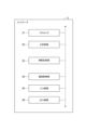
- FIG. 1 is a diagram showing a hydrocarbon production system.
- FIG. 2 is a diagram showing the structure of the reactor.
- FIG. 3 is a diagram showing the configuration of the controller.
- FIG. 4 is a flow diagram showing the operation of the controller.
- FIG. 5 is a diagram showing a hydrocarbon production apparatus according to an embodiment.
- FIG. 6 is a diagram showing a reactor included in a modified hydrocarbon production apparatus.
- a hydrocarbon production facility receives a raw material gas containing hydrogen and carbon and causes the raw material gas to react using a first catalyst heated to a predetermined temperature, thereby producing a first catalyst containing hydrocarbons.
- the controller provides a first control signal that causes heat to be supplied to each of the first reactor and the second reactor, and a second control signal that causes heat to be supplied to only one of the first reactor and the second reactor. Selectively output to a heat supplier.
- the controller selects either the first control signal or the second control signal based on the amount of hydrogen contained in the source gas.
- the hydrocarbon production facility has an aspect in which the heat medium is supplied to both the first reactor and the second reactor based on the amount of hydrogen contained in the raw material gas, and the heat medium is supplied to the first reactor and the second reactor. It switches between a mode of supplying to only one side and a mode of supplying to only one side. As a result, when the amount of hydrogen supplied to the hydrocarbon production facility is small, the heating medium is supplied to only one of the first reactor and the second reactor to maintain the reaction. The amount of heat to be supplied can be reduced. Therefore, the hydrocarbon production facility can improve the energy efficiency in the operation of generating the gas containing hydrocarbons from the raw material gas.
- the heat supply device of the hydrocarbon production facility includes a heat medium flow path through which the heat medium supplied to the first reactor and the second reactor flows, and a heat control unit that exchanges heat with the heat medium. may have.
- the heat medium flow path section includes a first heat medium flow path connected to the first reactor, a second heat medium flow path connecting the first reactor to the second reactor, and a second heat medium flow path connected to the second reactor. and a third heat medium flow path. According to this configuration, the heat medium supplied with heat in the heat control unit is supplied to the first reactor and the second reactor. As a result, the amount of heat required for the reaction can be provided to the first catalyst and the second catalyst.
- the heat medium flow path portion of the hydrocarbon production facility includes a heat medium bypass flow path that connects the second heat medium flow path to the third heat medium flow path, and a heat medium bypass flow path that connects the second heat medium flow path to the third heat medium flow path.
- a heating medium switching unit that switches between a mode of supplying the heating medium to the reactor and a mode of supplying the heating medium to the heating medium bypass channel without supplying the heating medium to the second reactor by receiving the second control signal. may have. According to this configuration, switching between a mode in which the heat medium is supplied to the second reactor and a mode in which the heat medium is not supplied to the second reactor can be realized with a simple configuration.
- the above hydrocarbon production equipment includes a first gas flow path connected to the first reactor, a second gas flow path connecting the first reactor to the second reactor, and a second gas flow path connected to the second reactor. a third gas flow path, a gas bypass flow path connecting the second gas flow path to the third gas flow path, and an aspect of supplying the first intermediate gas to the second reactor in response to receiving the first control signal; It may further include a gas switching unit that alternately switches between supplying the first intermediate gas to the gas bypass channel without supplying the first intermediate gas to the second reactor by receiving the second control signal. According to this configuration, switching between a mode in which the first intermediate gas is supplied to the second reactor and a mode in which the first intermediate gas is not supplied to the second reactor can be realized with a simple configuration.
- the controller of the hydrocarbon production facility includes a hydrogen amount obtaining unit for obtaining data regarding the amount of hydrogen contained in the raw material gas, and a first reaction when receiving the raw material gas containing the amount of hydrogen indicated by the data regarding the amount of hydrogen.
- Heat quantity comparison comparing the reaction heat quantity including the heat quantity generated by the reaction of the device and the heat quantity generated by the reaction of the second reactor, and the required heat quantity required to maintain the reaction of the first reactor and the reaction of the second reactor and a signal output unit that outputs a second control signal to the heat supplier when the amount of reaction heat is smaller than the required amount of heat. According to this controller, it is possible to easily determine the state in which heat should be supplied to only one of the first reactor and the second reactor.
- the first reactor of the hydrocarbon production facility may include at least two reactors connected in parallel with each other. With this configuration, it is possible to increase the amount of the first intermediate gas generated.
- a hydrocarbon production system which is another aspect of the present disclosure, includes a hydrogen supply facility that outputs hydrogen, and a hydrocarbon production facility that receives a raw material gas containing hydrogen and carbon and generates a gas containing hydrocarbons. .
- the hydrocarbon production facility receives a raw material gas containing hydrogen and carbon, and reacts the raw material gas using a first catalyst heated to a predetermined temperature to generate a first intermediate gas containing hydrocarbons.
- a second reactor for generating a second intermediate gas containing hydrocarbons by reacting the first intermediate gas with a second catalyst heated to a predetermined temperature, and heating the first catalyst a heat supplier for supplying heat for heating the second catalyst to the first reactor and supplying heat for heating the second catalyst to the second reactor; and a controller for controlling the operation of the heat supplier.
- the controller provides a first control signal that causes heat to be supplied to each of the first reactor and the second reactor, and a second control signal that causes heat to be supplied to only one of the first reactor and the second reactor. Selectively output to a heat supplier.
- the controller selects either the first control signal or the second control signal based on the amount of hydrogen contained in the source gas.
- the hydrocarbon production system is equipped with the above-mentioned hydrocarbon production equipment. Therefore, it is possible to improve the energy efficiency in the operation of generating gas containing hydrocarbons from raw material gas.
- a controller of a hydrocarbon production apparatus receives a raw material gas containing hydrogen and carbon, and causes the raw material gas to react using a first catalyst heated to a predetermined temperature, A second intermediate gas containing hydrocarbon is generated by reacting the first intermediate gas with a second catalyst heated to a predetermined temperature in a first reactor that generates a first intermediate gas containing hydrocarbon. and a second reactor that conducts.
- the controller of the hydrocarbon production device includes a hydrogen amount acquisition unit for obtaining data on the amount of hydrogen contained in the raw material gas, and when the hydrocarbon production device receives the raw material gas containing the amount of hydrogen indicated by the data on the amount of hydrogen, Compare the reaction heat quantity including the heat quantity generated by the reaction in the first reactor and the heat quantity generated by the reaction in the second reactor, and the required heat quantity required to maintain the reaction in the first reactor and the reaction in the second reactor and a heat amount comparison unit for supplying heat for heating the first catalyst to the first reactor when the amount of reaction heat is smaller than the required heat amount, and supplying heat for heating the second catalyst to the second reactor. and a signal output unit for outputting a control signal for supplying heat to only one of the first reactor and the second reactor with respect to the heat supplier capable of supplying heat.
- the controller of the hydrocarbon production device can determine the object to which the heat transfer medium is provided based on the amount of hydrogen contained in the raw material gas supplied to the hydrocarbon production device. Therefore, the controller of the hydrocarbon production device can improve the energy efficiency in the operation of the hydrocarbon production device to generate gas containing hydrocarbons from the raw material gas.
- a method for producing hydrocarbons using a hydrocarbon production apparatus uses a first catalyst in which a raw material gas containing hydrogen and carbon is received and the raw material gas is heated to a predetermined temperature.
- a method for producing hydrocarbons using a hydrocarbon production apparatus comprises the steps of: obtaining data on the amount of hydrogen contained in a source gas; , the amount of reaction heat including the amount of heat generated by the reaction in the first reactor and the amount of heat generated by the reaction in the second reactor, and the amount of heat required to maintain the reaction in the first reactor and the reaction in the second reactor. and supplying heat to the first reactor to heat the first catalyst and supplying heat to the second reactor to heat the second catalyst when the heat of reaction is less than the required heat of reaction. and outputting a control signal to a heat supplier that supplies heat to only one of the first reactor and the second reactor.
- the object to which the heat transfer medium is provided is determined based on the amount of hydrogen contained in the raw material gas supplied to the hydrocarbon production equipment. Therefore, the method for producing hydrocarbons can improve the energy efficiency in the operation of the hydrocarbon producing apparatus to generate gas containing hydrocarbons from raw material gas.
- the hydrocarbon production facility 1 is supplied with raw material gas.
- the hydrocarbon production facility 1 reacts raw material gas using a catalyst. As a result, the hydrocarbon production facility 1 produces product gas.
- Source gas includes hydrogen gas and carbon dioxide gas.
- the source gas may contain carbon monoxide gas instead of carbon dioxide gas.
- the hydrocarbon production facility 1 may have an input 1a for receiving hydrogen gas and an input 1b for receiving carbon dioxide gas.
- the hydrocarbon production facility 1 may have an input for receiving a raw material gas in which hydrogen gas and carbon dioxide gas are mixed.
- the product gas contains hydrocarbons.
- the hydrocarbon production facility 1 outputs product gas from the output 1c.
- the hydrocarbon production facility 1 is supplied with hydrogen gas from, for example, a water electrolysis device 101 (hydrogen supply facility).
- the water electrolyzer 101 receives power.
- the water electrolysis device 101 produces hydrogen from water.
- the power consumed by the water electrolysis device 101 is purchased from the power company 105, for example.
- Electric power consumed by the water electrolysis device 101 is supplied from a renewable energy facility 102 .
- the renewable energy facility 102 there is a photovoltaic power generation facility that uses sunlight, which is renewable energy.
- Renewable energy equipment 102 includes wind power generation equipment that uses wind power, which is renewable energy.
- Solar power plants and wind power plants are examples of renewable energy plants 102 .
- the power generation equipment that constitutes the renewable energy equipment 102 may be equipment that generates power using other renewable energy.
- the amount of power generated fluctuates depending on the weather and time of day. For example, a photovoltaic power generation facility cannot generate power at night in the first place. The amount of power generated by photovoltaic power generation equipment drops significantly during bad weather.
- the production of hydrogen by the water electrolysis device 101 may be performed using surplus power. Under these circumstances, the power supplied to the water electrolysis device 101 is likely to fluctuate, and as a result, the amount of hydrogen output by the water electrolysis device 101 is also likely to fluctuate. As a result, there occurs a timing when a sufficient amount of hydrogen gas cannot be supplied to the hydrocarbon production facility 1 .
- the water electrolysis device 101 is an alkaline water electrolysis device.
- the alkaline water electrolyzer may have a minimum load power for operational reasons. Alkaline water electrolyzers need to be supplied with power required for low-load operation. For example, when power cannot be supplied from the renewable energy facility 102, the alkaline water electrolyzer may receive power from a storage battery. Also, the alkaline water electrolyzer may be supplied with power purchased from the power company 105 .
- the hydrocarbon production facility 1 is further supplied with hydrogen gas from the hydrogen storage facility 103 (hydrogen supply facility).
- the hydrogen stored in the hydrogen storage facility 103 may be surplus hydrogen output from the water electrolysis device 101 .
- the hydrogen stored in the hydrogen storage facility 103 may be hydrogen transported from the outside.
- the hydrocarbon production facility 1 is supplied with carbon dioxide gas.
- Carbon dioxide gas is supplied, for example, from a carbon dioxide capture facility 104 .
- Hydrocarbon production facility 1 receives carbon dioxide gas from input 1b.
- a configuration including the hydrocarbon production facility 1 and at least one of the water electrolysis device 101 and the hydrogen storage facility 103 is referred to as a hydrocarbon production system 100.
- Hydrocarbon production system 100 may include the other of water electrolyzer 101 or hydrogen storage facility 103 and carbon dioxide recovery facility 104 .
- the hydrocarbon production system 100 includes the hydrocarbon production facility 1 and a facility for supplying raw materials to the hydrocarbon production facility 1 .
- the hydrocarbon production facility 1 has a hydrocarbon production device 2 and a controller 3 (controller).
- the hydrocarbon production device 2 produces a product gas from the raw material gas.
- a controller 3 controls the hydrocarbon production device 2 .
- the controller 3 may be connected to the hydrocarbon production apparatus 2 so as to be able to transmit the control signal ⁇ .
- the control signal ⁇ may be transmitted by wired communication.
- the control signal ⁇ may be transmitted by wireless communication.
- the controller 3 may be arranged near the hydrocarbon production device 2 .
- the controller 3 may be located remotely from the hydrocarbon production device 2 . Details of the controller 3 will be described later.
- the hydrocarbon production device 2 has a first reactor 21S, a second reactor 22S, a third reactor 23S, and a heat supplier 24.
- the first reactor 21S includes one reactor 21 .
- second reactor 22S also includes one reactor 22 .
- the third reactor 23 S also includes one reactor 23 .
- the reactor of the present disclosure contains one reactor. The number of reactors constituting the reactor is not limited to one. The reactor may consist of at least two reactors. Modifications of the reactor will be described later.
- the first reactor 21S, the second reactor 22S, and the third reactor 23S generate gases containing hydrocarbons by reacting raw material gases using catalysts.
- the first reactor 21S, the second reactor 22S and the third reactor 23S are interconnected by a plurality of gas pipes.
- the first reactor 21S, the second reactor 22S and the third reactor 23S are connected in series in this order.
- the first reactor 21S receives hydrogen gas from input 1a and carbon dioxide gas from input 1b.
- the first reactor 21S provides the resulting first intermediate gas to the second reactor 22S.
- a second reactor 22S receives a first intermediate gas.
- the second reactor 22S produces a second intermediate gas from the first intermediate gas.
- the second intermediate gas has a higher proportion of hydrocarbons than the first intermediate gas.
- the second reactor 22S provides the second intermediate gas to the third reactor 23S.
- a third reactor 23S receives a second intermediate gas.
- the third reactor 23S produces a product gas from the second intermediate gas.
- the product gas has a higher proportion of hydrocarbons than the second intermediate gas.
- the third reactor 23S provides the product gas from output 1c to the outside.
- the gas flow described above is realized by the gas flow path section 25 .
- the gas channel portion 25 includes a first gas pipe 251 (first gas channel), a second gas pipe 252 (second gas channel), a third gas pipe 253 (third gas channel), and a third gas channel. 4 gas lines 254 .
- a first gas line 251 connects the input 1a and the input 1b to the first reactor 21S.
- a second gas pipe 252 connects the first reactor 21S to the second reactor 22S.
- a third gas pipe 253 connects the second reactor 22S to the third reactor 23S.
- a fourth gas line 254 connects the third reactor 23S to the output 1c.
- the first reactor 21S, the second reactor 22S and the third reactor 23S have performance differences such as acceptable gas capacity, but basically have similar structures.
- the first reactor 21S synthesizes hydrocarbons using hydrogen gas and carbon dioxide gas as raw materials.
- methanation represented by formula (1) can be mentioned.
- a reaction for synthesizing a hydrocarbon compound from carbon dioxide also includes FT synthesis represented by formula (2).
- Methanation and FT synthesis generally use catalysts and react at high temperatures of 200°C or higher. Since a catalyst that is active at high temperatures is used, it is necessary to preheat the catalyst to a high temperature using the heat transfer medium HM.
- the heat medium HM include oil, steam, molten salt, and the like.
- FIG. 2 is an illustration of the internal structure of the reactor 21 provided in the first reactor 21S.
- the reactor 21 has a shell 211 , multiple tubes 212 and a buffer 213 .
- Shell 211 constitutes the outer shell of reactor 21 .
- the shell 211 has a gas inlet 211a, a gas outlet 211b, a heat medium inlet 211c, and a heat medium outlet 211d.
- the gas inlet 211a is connected by a plurality of tubes 212 to the gas outlet 211b.
- a catalyst CT first catalyst
- a reaction occurs when the source gas passes through the catalyst CT placed in the tube 212 .
- Heat medium inlet 211 c is connected to heat medium outlet 211 d via a space surrounded by shell 211 , tube 212 and partition wall 215 .
- the region in which the gas flows and the region in which the heat medium HM flows are separated by the tube 212 and the partition wall 215 .
- the heat medium HM flows from the heat medium inlet 211c to the heat medium outlet 211d while contacting the outer peripheral surface of the tube 212.
- heat exchange is performed between the heat medium HM and the catalyst CT via the outer peripheral surface of the tube 212.
- FIG. Heat exchange includes a mode in which heat is transferred from the heat medium HM to the catalyst CT.
- the heat exchange also includes a mode in which heat is transferred from the catalyst CT to the heat medium HM. For example, oil at 300 to 330 degrees Celsius is supplied from the heat medium inlet 211c.
- the temperature of the oil discharged from the heat medium outlet 211d is lower than the temperature of the oil flowing into the heat medium inlet 211c.
- the temperature of the oil discharged from the heat medium outlet 211d is higher than the temperature of the oil flowing into the heat medium inlet 211c.
- the heat supplier 24 supplies the heat medium HM to each of the first reactor 21S, the second reactor 22S and the third reactor 23S.
- the amount of heat generated in the first reactor 21S, the second reactor 22S, and the third reactor 23S increases or decreases depending on the state of the reaction. For example, when the amount of heat generated is small, the heat medium HM supplies heat to the catalysts CT provided in the first reactor 21S, the second reactor 22S, and the third reactor 23S. For example, when a large amount of heat is generated, the heat medium HM takes heat from each catalyst CT. By circulating the heat medium HM, the catalyst CT provided in the first reactor 21S, the second reactor 22S and the third reactor 23S can be maintained at a predetermined temperature.
- the heat supplier 24 has a heat control device 241 (heat control section) and a heat medium flow path section 242 .
- the heat supplier 24 is allowed to include components other than the heat control device 241 and the heat medium channel portion 242 .
- the heat control device 241 has a function of giving heat to the heat medium HM and a function of taking heat from the heat medium HM.
- the heat control device 241 may include a heater 241a for the function of applying heat to the heat medium HM.
- the heat control device 241 may include a heat exchanger 241b for the function of taking heat from the heat medium HM.
- heat exchanger 241b may be a cooler.
- the heat control device 241 may include a pump 241c for moving the heat medium HM.
- the heat exchanger 241b, the pump 241c, and the heater 241a may be connected in this order along the direction in which the heat medium HM flows.
- Both the methanation represented by the above formula (1) and the FT reaction represented by the formula (2) are exothermic reactions.
- the temperature of the catalyst CT rises sharply. Therefore, it is necessary to control the temperature of the catalyst CT so that the generated heat is removed and the temperature of the catalyst CT falls within a predetermined range.
- the heat control device 241 can also be used for heat control to keep the temperature of the catalyst CT within a predetermined range.
- the heat medium flow path portion 242 includes a first heat medium pipe 242a (first heat medium flow path), a second heat medium pipe 242b (second heat medium flow path), and a third heat medium pipe 242c (third heat medium flow path). medium flow path) and a fourth heat medium pipe 242d. These pipes allow the heat medium HM to flow through the closed flow path.
- a first heat medium pipe 242 a connects the first reactor 21 S to the heat control device 241 .
- the second heat medium pipe 242b connects the first reactor 21S to the second reactor 22S.
- the third heat medium pipe 242c connects the second reactor 22S to the third reactor 23S.
- a fourth heat medium pipe 242d connects the heat control device 241 to the third reactor 23S.
- the heat medium HM flows through the third reactor 23S, the second reactor 22S, and the first reactor 21S in this order. That is, the direction in which the heat medium HM flows is opposite to the direction in which the gas flows.
- the hydrocarbon production device 2 basically generates product gas with three reactors (reactors). Hydrocarbon production unit 2 can also produce product gas with two reactors, if desired. In the illustration of FIG. 1, the hydrocarbon production unit 2 can produce product gas by means of a first reactor 21S, a second reactor 22S and a third reactor 23S. The hydrocarbon production device 2 can also produce product gas by means of the first reactor 21S and the third reactor 23S. The hydrocarbon production apparatus 2 can select a state in which the second reactor 22S is used and a state in which the second reactor 22S is not used in the generation of the product gas.
- the state in which the second reactor 22S is used in other words, means the state in which the temperature of the catalyst CT (second catalyst) of the second reactor 22S is maintained in a state where the reaction is possible.
- a state in which the second reactor 22S is not used in other words, means a state in which the temperature of the catalyst CT of the second reactor 22S is not maintained in a state where reaction is possible.
- the temperature of the catalyst CT in the second reactor 22S is determined by the amount of heat generated by the reaction and the amount of heat supplied by the heat medium HM. Also, the temperature of the catalyst CT of the second reactor 22S is determined by the amount of heat generated by the reaction and the amount of heat taken away by the heat medium HM. For example, if the amount of heat generated by the reaction is small and the supply of heat from the heat medium HM is stopped, the temperature of the catalyst CT in the second reactor 22S cannot be maintained. When the supply of heat by the heat medium HM is stopped, a state in which the second reactor 22S is not used can be achieved.
- the heat medium flow path section 242 has a configuration for switching between supplying and stopping the supply of the heat medium HM to the second reactor 22S. Specifically, the heat medium flow path section 242 has a heat medium bypass pipe 242P (heat medium bypass flow path) and a heat medium switching device 242S (heat medium switching section).
- the heat medium bypass pipe 242P connects the third heat medium pipe 242c to the second heat medium pipe 242b. Specifically, the first end of the heat medium bypass pipe 242P is connected to the second heat medium pipe 242b. A second end of the heat medium bypass pipe 242P is connected to the third heat medium pipe 242c. A heat medium switch 242S is provided at the second end of the heat medium bypass pipe 242P. The heat medium selector 242S switches between a configuration in which the heat medium HM provided from the third reactor 23S is supplied to the second reactor 22S and a configuration in which it is supplied to the heat medium bypass pipe 242P. The switching operation of the heat medium switching device 242S follows the control signal ⁇ from the controller 3 .
- the heat medium switch 242S may be composed of, for example, two valves as shown in FIG. When the heat medium HM flows through the heat medium bypass pipe 242P, the heat medium HM is not supplied to the second reactor 22S.
- the hydrocarbon production device 2 may have a configuration for bypassing the gas in addition to the configuration for bypassing the heat medium HM.
- the gas flow path section 25 may have a gas bypass pipe 25P (gas bypass flow path) and a gas switcher 25S (gas switching section).
- the gas bypass pipe 25P connects the second gas pipe 252 to the third gas pipe 253. Specifically, the first end of the gas bypass pipe 25P is connected to the second gas pipe 252 . A second end of the gas bypass pipe 25P is connected to a third gas pipe 253 . A gas switch 25S is provided at the first end of the gas bypass pipe 25P. The gas switcher 25S switches between the configuration of supplying the first intermediate gas generated by the first reactor 21S to the second reactor 22S and the configuration of supplying it to the gas bypass pipe 25P. The switching operation of the gas switcher 25S follows the control signal ⁇ from the controller 3 . For example, when the first intermediate gas flows through the gas bypass pipe 25P, the first intermediate gas is not supplied to the second reactor 22S.
- the controller 3 outputs a control signal ⁇ for switching between a state in which the second reactor 22S is used and a state in which the second reactor 22S is not used.
- the controller 3 outputs the first control signal ⁇ when using the second reactor 22S.
- the controller 3 outputs the first control signal ⁇ when supplying the heat medium HM and the gas to the second reactor 22S.
- the controller 3 outputs the second control signal ⁇ when the second reactor 22S is not used.
- the controller 3 outputs the second control signal ⁇ when the heating medium HM and the gas are not supplied to the second reactor 22S.
- the controller 3 is implemented by a computer having the hardware configuration shown in FIG. Controller 3 includes one or more computers.
- the computer has a processor 31 , a main storage section 32 , an auxiliary storage section 33 , a communication control section 34 , an input device 35 and an output device 36 .
- the controller 3 is composed of one or a plurality of computers composed of these hardware and software such as programs.
- controller 3 is composed of multiple computers, these computers may be locally connected. Multiple computers may be connected to each other via a communication network such as the Internet or an intranet. This connection logically constructs one controller 3 .
- the processor 31 executes an operating system, application programs, and the like.
- the main storage unit 32 is composed of ROM (Read Only Memory) and RAM (Random Access Memory).
- the auxiliary storage unit 33 is a storage medium including a hard disk, flash memory, and the like. Auxiliary storage unit 33 generally stores a larger amount of data than main storage unit 32 .
- the communication control unit 34 is composed of a network card or a wireless communication module. Auxiliary storage unit 33 generally stores a larger amount of data than main storage unit 32 .
- the input device 35 includes a keyboard, mouse, touch panel, voice input microphone, and the like.
- the output device 36 is composed of a display, a printer, and the like.
- the auxiliary storage unit 33 stores programs and data necessary for processing in advance.
- the program causes the computer to execute each functional element of the controller 3 .
- the program causes the computer to execute, for example, a process related to a method for producing hydrocarbons.
- the program is read by the processor 31 or the main storage unit 32 and causes at least one of the processor 31, the main storage unit 32, the auxiliary storage unit 33, the communication control unit 34, the input device 35, and the output device 36 to operate.
- the program executes reading and writing of data in the main storage section 32 and the auxiliary storage section 33 .
- the program may be provided after being recorded on a tangible storage medium such as a CD-ROM, DVD-ROM, or semiconductor memory.
- the program may be provided as a data signal over a communications network.
- FIG. 4 is a flowchart showing the operation of the controller 3. According to the flow of FIG. 4, it is possible to select which of the first control signal .theta. and the second control signal .theta.
- the controller 3 acquires data (variable X) indicating the amount of hydrogen gas contained in the raw material gas (step S101).
- the amount of hydrogen gas may be treated as volumetric flow rate (m 3 /s), for example.
- the configuration in which the controller 3 acquires the flow rate data ⁇ (variable X) is not particularly limited.
- controller 3 may obtain flow data ⁇ from flow sensor 106 (see FIG. 1).
- the controller 3 compares the heat amounts.
- the operation of comparing the heat amounts includes an operation of obtaining the reaction heat amount (step S102) and an operation of comparing the reaction heat amount and the required heat amount (step S103).
- the controller 3 outputs a control signal ⁇ for switching between a state in which the second reactor 22S is used and a state in which the second reactor 22S is not used.
- the controller 3 selects the control signal ⁇ based on the amount of heat generated by the reaction and the amount of heat required to maintain the reaction (variable Y).
- the amount of heat generated by the reaction is not less than the amount of heat required to maintain the reaction (variable Y)
- the source gas is sufficiently supplied. Therefore, it is not necessary to stop the second reactor 22S.
- the amount of heat generated by the reaction is sufficient, the heat of reaction alone can maintain the temperature of the hydrocarbon reactor.
- This state is a so-called thermally independent state in which heat supply is unnecessary.
- the energy consumed by the hydrocarbon production apparatus 2 is only operating power such as energy for driving the pump 591 (see FIG. 5) that circulates the heat medium HM.
- the amount of heat generated by the reaction is less than the amount of heat required to maintain the reaction (variable Y), the raw material gas is not sufficiently supplied. In such situations, it is possible that no reaction has taken place. Alternatively, the reaction amount may be small. Even in these cases, it is possible to cause the reaction to occur in the second reactor 22S.
- the temperature of the catalyst CT must be maintained. That is, heat must be supplied. Heat is supplied, for example, by providing a heat medium HM. Providing the heat medium HM will continue to supply heat in order to obtain a small amount of product (hydrocarbons). Therefore, energy efficiency tends to decrease.
- the hydrocarbon production apparatus 2 that employs the methanation shown in formula (1) and the FT reaction shown in formula (2) often includes a plurality of reactors.
- the scale of the hydrocarbon production apparatus 2 equipped with multiple reactors is large.
- the operation to maintain the temperature also requires a huge amount of energy. Therefore, when the amount of heat generated by the reaction is less than the amount of heat required to maintain the reaction (variable Y), it is better to stop the supply of the heating medium HM and the gas to the second reactor 22S. and energy efficient. Therefore, the controller 3 selects the second control signal ⁇ for stopping the supply of the heat medium HM and the gas to the second reactor 22S.
- the controller 3 determines whether or not the amount of reaction heat is smaller than the required amount of heat. This is because if the amount of reaction heat is smaller than the required amount of heat, power will be consumed to maintain the temperature of the catalyst CT.
- the reaction heat quantity and the required heat quantity it is possible to automatically control the timing to start flowing the heat medium HM to the heat medium bypass pipe 242P and the timing to start flowing the intermediate gas to the gas bypass pipe 25P.
- X Amount of hydrogen produced by the water electrolysis device 101 [m 3 /s] a: the ratio of the amount of methane produced to the amount of hydrogen supplied (eg 0.25) b: volume per unit mole [m 3 /mol] (eg 0.0224) c: calorific value per unit mole [kJ/mol] (165) Y: Amount of heat released during low-load operation of the hydrocarbon production device 2 [kW]
- the values obtained by the variables X, a and b are the amount of methane obtained as a result [mol/ s].
- the amount of reaction heat is obtained (step S102).
- the amount of hydrogen production (variable X) can also be said to be the amount of hydrogen that the hydrocarbon production facility 1 receives. Derivation of the hydrogen production amount may employ various methods depending on factors such as the state, capacity and control system of the hydrocarbon production facility 1 . Illustrate some specific examples.
- the amount of hydrogen production is obtained as the average value of the amount of hydrogen output by the water electrolysis device 101 . It can be said that the first specific example assumes prediction of the local hydrogen production amount.
- the power required for hydrogen production is obtained from the renewable energy facility 102, the amount of power generated may be locally reduced due to the influence of clouds or wind. Therefore, the average value of the amount of hydrogen produced by the water electrolysis device 101 in the most recent several minutes to several hours may be used with reference to the timing at which steps S102 and S103 are executed.
- the amount of hydrogen production is obtained from the remaining amount of hydrogen in the hydrogen storage facility.
- the renewable energy installation 102 is a photovoltaic installation
- the renewable energy installation 102 cannot supply power at night.
- the amount of hydrogen produced is extremely reduced. That is, when operating the hydrocarbon production facility 1 at night, hydrogen is supplied from the hydrogen storage facility 103 . Therefore, the remaining amount of hydrogen in the hydrogen storage facility 103 limits the production amount of the product gas.
- the amount of hydrogen production is obtained from the amount of power generated by the renewable energy facility 102 . Based on the weather forecast, etc., the amount of power generated by photovoltaic power generation for each hour of the day is predicted. If the power generation amount can be predicted, the hydrogen production amount of the water electrolysis device 101 to which power is supplied can be predicted. In a third specific example, it is possible to predict the amount of hydrogen produced. Therefore, an operation plan for the hydrocarbon production facility 1 can be determined before actual operation is started.
- the reaction heat generated by the reaction that produces hydrocarbons is heat-exchanged with the heat medium HM inside the first reactor 21S, the second reactor 22S, and the third reactor 23S. That is, the heat is removed.
- the heat medium HM is heated by reaction heat.
- heat is generated in the hydrocarbon production facility 1 as a whole.
- the heat release amount (variable Y [kW]) in the entire hydrocarbon production facility 1 can be measured in advance.
- the amount of hydrogen produced by the water electrolysis device 101 determines whether the temperature of the first reactor 21S, the second reactor 22S, and the third reactor 23S can be maintained or cannot be maintained. can be judged.
- the temperature of the catalyst is kept constant while an inert gas such as nitrogen gas is supplied to the three reactors 21S, 22S and 23S.
- an inert gas such as nitrogen gas
- the amount of heat supplied to the catalyst CT by the heat medium HM can be considered to be equivalent to the amount of heat received by the heat medium HM from the heater of the heat control device 241 . Therefore, by measuring the amount of heat given from the heater to the heat medium HM in order to keep the temperature of the catalyst constant, the amount of heat released can be known.
- the amount of heat released is the amount of heat that should be supplied to maintain the temperature of the catalyst. Therefore, the amount of heat released is the amount of heat required to maintain the reaction.
- step S103 "the amount of heat generated by the reaction is less than the amount of heat required to maintain the reaction (variable Y)" or “the amount of heat generated by the reaction is less than the amount of heat required to maintain the reaction (variable Y) not less than” is obtained.
- the controller 3 outputs the first control signal ⁇ or the second control signal ⁇ to the heating medium switching device 242S and the gas switching device 25S according to the result of step S103.
- the controller 3 outputs the first control signal ⁇ (step S104).
- the controller 3 outputs the second control signal ⁇ (step S105).
- the controller 3 realizes the above operations by the computer executing the program. As shown in FIG. 1, the controller 3 has functional components for realizing the above operations.
- the controller 3 has a hydrogen amount acquisition unit 3a, a heat amount comparison unit 3b, and a signal output unit 3c. The functions performed by these elements are realized by executing a program by the processor 31 .
- the hydrogen amount acquisition unit 3a acquires flow rate data ⁇ (variable X) regarding the amount of hydrogen that the hydrocarbon production facility 1 can accept.
- the hydrogen amount acquisition unit 3a executes step S101.
- the calorie comparison unit 3b outputs either "reaction calorie is less than required calorie” or "reaction calorie is not less than required calorie”.
- the heat quantity comparison unit 3b executes steps S102 and S103. Specifically, the calorie comparison unit 3b calculates the reaction calorie using the data (variable X) regarding the amount of hydrogen (step S102). The calorie comparison unit 3b reads out the required calorie stored in advance. Then, the heat quantity comparison unit 3b compares the calculated reaction heat quantity with the read required heat quantity (step S103). As a result, the calorie comparison unit 3b outputs either "reaction calorie is less than required calorie” or "reaction calorie is not less than required calorie”.
- the signal output section 3c outputs either the first control signal ⁇ or the second control signal ⁇ to the heat medium flow path section 242 and the gas flow path section 25 based on the result output by the heat quantity comparison section 3b.
- the signal output unit 3c executes steps S104 and S105.
- the hydrocarbon production facility 1 receives a raw material gas containing hydrogen and carbon, and reacts the raw material gas using a catalyst CT heated to a predetermined temperature to generate a first intermediate gas containing hydrocarbons.
- a heat supplier 24 capable of supplying heat for heating the catalyst CT to the first reactor 21S and supplying heat for heating the catalyst CT to the second reactor 22S, and the operation of the heat supplier 24 is controlled.
- the controller 3 selectively selects a first control signal ⁇ for supplying heat to each of the first reactor 21S and the second reactor 22S and a second control signal ⁇ for supplying heat only to the first reactor 21S. is output to the heat supplier 24 at .
- the controller 3 selects either the first control signal ⁇ or the second control signal ⁇ based on the amount of hydrogen contained in the source gas.
- the hydrocarbon production facility 1 supplies the heat medium HM to the first reactor 21S, the second reactor 22S, and the third reactor 23S based on the amount of hydrogen contained in the raw material gas.
- the mode of supplying to the first reactor 21S and the third reactor 23S is switched.
- the heating medium HM is supplied to the first reactor 21S and the third reactor 23S.
- the amount of heat to be supplied to maintain the reaction in the second reactor 22S can be reduced. Therefore, the hydrocarbon production facility 1 can improve the energy efficiency in the operation of generating the gas containing hydrocarbons from the raw material gas.
- the hydrocarbon production facility 1 uses hydrogen, carbon monoxide, or carbon dioxide as raw materials to produce hydrocarbons.
- the hydrocarbon production facility 11 includes a plurality of first reactors 21S, second reactors 22S and third reactors 23S each having a catalyst for producing hydrocarbons.
- a heating medium bypass pipe 242P and a gas bypass pipe 25P, which are bypass lines, are provided in the first reactor 21S, the second reactor 22S and the third reactor 23S.
- the heat medium bypass pipe 242P and the gas bypass pipe 25P are used to selectively prevent the source gas and the heat medium HM from flowing. Since the hydrocarbon production facility 11 can limit the distribution range of the high-temperature raw material gas, the high-temperature intermediate gas, and the heat medium HM, it is possible to reduce heat consumption.
- the hydrocarbon production facility 1 uses the water electrolysis device 101 that continues to produce hydrogen under a low load condition at night and in bad weather to operate the hydrocarbon production facility 11 at a low load. can be put into operation.
- the water electrolysis device 101 that continues to produce hydrogen under a low load condition at night and in bad weather to operate the hydrocarbon production facility 11 at a low load. can be put into operation.
- the hydrocarbon production facility 11 circulates the raw material gas and the heat medium HM, and the number of the first reactor 21S, the second reactor 22S, and the third reactor 23S for producing hydrocarbons is reduced to the number of the hydrogen generation equipment such as the water electrolysis device 101.
- the amount of hydrogen supplied from the device, the remaining amount of hydrogen stored in the hydrogen storage facility, the amount of power actually output by the renewable energy facility 102, and the predicted amount of power that the renewable energy facility 102 will output Switch automatically or manually depending on your needs.
- the above-described hydrocarbon production facility 11 increases energy efficiency in the production of hydrocarbon-containing product gas by relating the amount of hydrogen acceptable to the hydrocarbon production facility 11 and the amount of hydrocarbon production.
- the heat supplier 24 of the hydrocarbon production facility 1 exchanges heat with the heat medium flow path portion 242 through which the heat medium HM exchanges heat with the first reactor 21S and the second reactor 22S. and a thermal control device 241 .
- the heat medium channel portion 242 includes a first heat medium pipe 242a connected to the first reaction device 21S, a second heat medium pipe 242b connecting the first reaction device 21S to the second reaction device 22S, and a second reaction device 22S. and a third heat medium pipe 242c connected to the device 22S.
- the heat medium HM supplied with heat by the heat control device 241 is supplied to the first reactor 21S and the second reactor 22S.
- the amount of heat required for the reaction can be provided to the catalyst CT.
- the heat medium flow path portion 242 of the hydrocarbon production facility 1 includes a heat medium bypass pipe 242P connecting the second heat medium pipe 242b to the third heat medium pipe 242c, and the heat medium HM by receiving the first control signal ⁇ .
- the hydrocarbon production facility 1 includes a first gas pipe 251 connected to the first reactor 21S, a second gas pipe 252 connecting the first reactor 21S to the second reactor 22S, and the second reactor 22S.
- a connected third gas pipe 253 and a gas bypass pipe 25P connecting the second gas pipe 252 to the third gas pipe 253 are provided.
- the hydrocarbon production facility 1 supplies the first intermediate gas to the second reactor 22S by receiving the first control signal ⁇ , and supplies the first intermediate gas to the second reactor 22S by receiving the second control signal ⁇ .
- a gas switch 25S is provided to alternately switch between supplying to the gas bypass pipe 25P without supplying to 22S. According to this configuration, switching between a mode in which the first intermediate gas is supplied to the second reactor 22S and a mode in which the first intermediate gas is not supplied to the second reactor 22S can be realized with a simple configuration.
- the controller 3 includes a hydrogen amount acquisition unit 3a for obtaining data on the amount of hydrogen contained in the raw material gas, and when the raw material gas containing the amount of hydrogen indicated by the data on the amount of hydrogen is received, the hydrogen generated by the reaction in the first reactor 21S A heat amount comparison unit 3b for comparing the reaction heat amount including the heat amount and the heat amount generated by the reaction in the second reactor 22S with the required heat amount required to maintain the reaction in the first reactor 21S and the reaction in the second reactor 22S. and a signal output unit 3c that outputs a second control signal ⁇ to the heat supplier 24 when the amount of reaction heat is smaller than the required amount of heat. According to the controller 3, it is possible to easily determine the state in which heat should be supplied to only one of the first reactor 21S and the second reactor 22S.
- the hydrocarbon production system 100 includes a water electrolysis device 101 that outputs hydrogen, and a hydrocarbon production facility 1 that receives a raw material gas containing hydrogen and carbon and generates a gas containing hydrocarbons.
- the hydrocarbon production facility 1 receives a raw material gas and reacts the raw material gas with a catalyst CT heated to a predetermined temperature to generate a first intermediate gas containing hydrocarbons;
- a second reactor 22S that generates a second intermediate gas containing hydrocarbons by reacting the catalyst CT heated to a temperature of 100° C. with the first intermediate gas, and the heat for heating the catalyst CT is supplied to the first reactor 22S.
- the controller 3 provides a first control signal ⁇ for supplying heat to each of the first reactor 21S and the second reactor 22S, and a second control signal ⁇ for supplying heat to only one of the first reactor 21S and the second reactor 22S. and a control signal ⁇ are selectively output to the heat supplier 24 .
- the controller 3 selects either the first control signal ⁇ or the second control signal ⁇ based on the amount of hydrogen contained in the source gas.
- the hydrocarbon production system 100 includes the hydrocarbon production facility 1 described above. Therefore, the hydrocarbon production system 100 can improve the energy efficiency in the operation of generating the gas containing hydrocarbons from the raw material gas.
- the controller 3 of the hydrocarbon production apparatus 2 includes a hydrogen amount acquisition unit 3a for obtaining data on the amount of hydrogen contained in the raw material gas, and the hydrocarbon production apparatus 2 receives the raw material gas containing the amount of hydrogen indicated by the data on the amount of hydrogen.
- the reaction heat amount including the heat amount generated by the reaction in the first reactor 21S and the heat amount generated by the reaction in the second reactor 22S, the reaction in the first reactor 21S and the reaction in the second reactor 22S.
- a heat quantity comparison unit 3b for comparing the required heat quantity with the required heat quantity
- a signal output unit 3c for outputting a control signal ⁇ for supplying heat to only one of the first reactor 21S and the second reactor 22S with respect to the heat supplier 24 that supplies heat to the second reactor 22S; have.
- the controller 3 of the hydrocarbon production device 2 can determine the object to which the heat medium HM is provided based on the amount of hydrogen contained in the raw material gas supplied to the hydrocarbon production device 2 . Therefore, the controller 3 of the hydrocarbon production device 2 can improve the energy efficiency of the operation performed by the hydrocarbon production device 2 to generate gas containing hydrocarbons from the raw material gas.
- the method for producing hydrocarbons includes step S101 of obtaining data on the amount of hydrogen contained in the raw material gas, and when the hydrocarbon producing apparatus 2 receives the raw material gas containing the amount of hydrogen indicated by the data on the amount of hydrogen, the first The amount of reaction heat including the amount of heat generated by the reaction in the reactor 21S and the amount of heat generated by the reaction in the second reactor 22S, the amount of heat required to maintain the reaction in the first reactor 21S and the reaction in the second reactor 22S, and the heat supply device 24 capable of supplying heat for heating the catalyst CT to the first reactor 21S and the second reactor 22S when the reaction heat quantity is smaller than the required heat quantity. and a step S105 of outputting a control signal ⁇ for supplying heat only to one reactor 21S.
- the object to which the heat medium HM is provided is determined based on the amount of hydrogen contained in the raw material gas supplied to the hydrocarbon producing apparatus 2. Therefore, the method for producing hydrocarbons can improve the energy efficiency of the operation performed by the hydrocarbon producing apparatus 2 to generate gas containing hydrocarbons from the raw material gas.
- FIG. 5 shows a specific example of the hydrocarbon production device 5.
- the hydrocarbon production device 5 includes three reactors 51 , 52 and 53 .
- the reactors 51 and 52 are thermally controlled by a heat medium.
- a heat exchanger 541 is provided in the reactor 51 for preheating the source gas.
- a heat exchanger 542 is provided in the reactor 52 .
- Reactor 53 is thermally controlled by heater 5H.
- the reactor 51 receives the raw material gas provided from the mass flow controllers 551 and 552 via the heat exchanger 541 .
- a pipe for receiving a heat medium is connected to the reactor 51 .
- the heat transfer medium does not bypass the reactor 51 .
- Reactor 51 outputs the produced intermediate gas to tank 561 via heat exchanger 541 and heat exchanger 571 .
- the intermediate gas contains hydrocarbons such as methane as products and water.
- Heat exchanger 571 condenses water by cooling the intermediate gas. Water liquefied by condensation accumulates in tank 561 .
- Tank 561 outputs intermediate gas containing hydrocarbons to reactor 52 while water is removed.
- the reactor 52 receives the intermediate gas from the tank 561 via the heat exchanger 542.
- Reactor 52 outputs the intermediate gas produced through heat exchanger 572 to tank 562 .
- the roles of heat exchanger 572 and tank 562 are described above.
- the piping that guides the intermediate gas to the reactor 52 includes a route that leads the intermediate gas to the reactor 52 and a route that avoids the reactor 52 and leads the intermediate gas directly to the reactor 53 .
- the path through which the intermediate gas flows is controlled by two valves 581 and 582 . When valve 581 is closed and valve 582 is opened, the intermediate gas is led to reactor 52 . On the other hand, when the valve 581 is opened and the valve 582 is closed, the intermediate gas bypasses the reactor 52 and is led to the reactor 53 .
- a pipe for receiving a heat medium is connected to the reactor 52 in the same manner as the reactor 51 .
- the heat medium piping provided in the reactor 52 includes a route for guiding the heat medium to the reactor 52 and a route for guiding the heat medium to the reactor 51 without leading the heat medium to the reactor 52 .
- the path through which the heat medium flows is controlled by two valves 583 and 584 .
- the valve 583 is closed and the valve 584 is opened, the heat transfer medium is led to the reactor 52 .
- the valve 583 is opened and the valve 584 is closed, the heat medium avoids the reactor 52 and is led to the reactor 51 .
- the opening and closing of the valves 583 and 584 can be controlled by the operations of steps S104 and S105 executed by the controller 3 . As a result, the reactor 52 can be operated without flowing the heat medium and the intermediate gas. Therefore, the amount of heat radiation can be reduced.
- the reactor 53 receives the intermediate gas from the reactor 51 or the reactor 52. Reactor 53 outputs the produced intermediate gas to tank 563 via heat exchanger 573 .
- the roles of heat exchanger 573 and tank 563 are as described above.
- the heat release amount (variable Y) of the hydrocarbon production apparatus 2 shown in FIG. 5 is 9 kW.
- the heat quantity can be expected to be reduced by about 1/3.
- the amount of hydrogen produced is small and heat generation of 6 kW cannot be expected, such as at night or in bad weather, the intermediate gas and heat medium are not supplied to the reactor 52 .
- the hydrocarbon production facility 1 shown in FIG. 1 was equipped with three first reactors 21S, second reactors 22S and third reactors 23S.
- the hydrocarbon production facility 1 may be equipped with two or more reactors.
- the hydrocarbon production facility 1 may have two reactors.
- the hydrocarbon production facility 1 may have four reactors.
- the hydrocarbon production facility 1 shown in FIG. 1 has a configuration in which only the second reactor 22S bypasses the intermediate gas and the heat medium HM.
- the hydrocarbon production facility 1 may have a configuration in which only the first reactor 21S bypasses the intermediate gas and the heat medium HM.
- the hydrocarbon production facility 1 may have a configuration in which only the third reactor 23S bypasses the intermediate gas and the heat medium HM.
- the hydrocarbon production facility 1 may have a configuration in which the first reactor 21S and the second reactor 22S bypass the intermediate gas and the heat medium HM.
- the hydrocarbon production facility 1 may have a configuration in which the first reactor 21S and the third reactor 23S bypass the intermediate gas and the heat medium HM.
- the hydrocarbon production facility 1 may have a configuration in which the second reactor 22S and the third reactor 23S bypass the intermediate gas and the heat medium HM. Furthermore, the hydrocarbon production facility 1 may have a configuration in which the first reactor 21S, the second reactor 22S and the third reactor 23S bypass the intermediate gas and the heat medium HM.
- step S103 one of the two control signals ⁇ was selected depending on whether the relationship of expression (3) is satisfied, but one of the three operation patterns is selected using a plurality of conditional expressions. You may do so.
- the hydrocarbon production facility 1 shown in FIG. 1 employs a configuration in which the heat medium HM is circulated as the heat supplier 24 .
- the heat supplier 24 may be a heater provided in each of the first reactor 21S, the second reactor 22S and the third reactor 23S.
- the controller 3 outputs, for example, a control signal ⁇ for supplying current to the heater provided in the second reactor 22S and a control signal ⁇ for stopping the current.
- the controller 3 can suppress energy consumption by stopping the current flowing to the heater when the condition shown in Expression (3) is satisfied.
- the heat supply device 24 may have a configuration for heat supply by the heat medium HM and a configuration for heat supply by a heater. For example, heat may be supplied to the first reactor 21S and the second reactor 22S by the heat medium HM. Heat may be supplied to the third reactor 23S by a heater.
- a modified hydrocarbon production apparatus 2A may include a first reactor 21K.
- the first reactor 21K includes a first reactor 21a and a second reactor 21b.
- the first-stage reactor for receiving the raw material gas includes a plurality of reactors.
- the second reactor 22S and/or the third reactor 23S may also consist of multiple reactors.
- the first reactor 21K has a gas input 21Ka for receiving hydrogen gas and a gas input 21Kb for receiving carbon gas.
- a first gas pipe 251 is connected to the gas input 21Ka.
- a first gas pipe 251 is also connected to the gas input 21Kb.
- the first reactor 21K has a gas output 21Kc that outputs the generated intermediate gas to the second reactor 22S.
- a second gas pipe 252 is connected to the gas output 21Kc.
- the gas input 21Ka is connected to the first gas internal pipe 21Ha.
- the first gas internal pipe 21Ha has a branched portion.
- a first output of the first gas internal pipe 21Ha is connected to the first reactor 21a.
- a second output of the first gas internal pipe 21Ha is connected to the second reactor 21b.
- hydrogen gas is distributed to the first reactor 21a and the second reactor 21b, respectively.
- Gas input 21Kb is connected to second internal piping 21Hb.
- a first output of the second internal pipe 21Hb is connected to the first reactor 21a.
- a second output of the second internal pipe 21Hb is connected to the second reactor 21b.
- the carbon gas is distributed to the first reactor 21a and the second reactor 21b, respectively.
- the output of the first reactor 21a is connected to the input end of the third internal pipe 21Hc.
- the output of the second reactor 21b is connected to another input end of the third internal piping 21Hc.
- the third internal pipe 21Hc has a confluence.
- the intermediate gas generated by the first reactor 21a and the intermediate gas generated by the second reactor 21b are combined.
- the merged intermediate gas is sent to the second reactor 22S from the gas output 21Kc.
- the first reactor 21K has a configuration for supplying a heat medium to each of the first reactor 21a and the second reactor 21b.
- the first reactor 21K has a heat transfer medium input 21Kd and a heat transfer medium output 21Ke.
- the heat medium input 21Kd receives the heat medium that has flowed out of the second reactor 22S or the heat medium that has flowed out of the third reactor 23S and has not passed through the second reactor 22S.
- a first heat medium internal pipe 21Ja is connected to the heat medium input 21Kd.
- the first heat medium internal pipe 21Ja is connected to the first reactor 21a.
- the first heat medium internal pipe 21Ja is also connected to the second reactor 21b. With this configuration, the first reactor 21a and the second reactor 21b can each receive a heat medium.
- a second heat medium internal pipe 21Jb is connected to the first reactor 21a.
- a second heating medium internal pipe 21Jb is also connected to the second reactor 21b.
- the second heat medium internal pipe 21Jb is connected to the heat medium output 21Ke.
- the second heat medium internal piping 21Jb receives the heat medium flowing out from the first reactor 21a and the second reactor 21b.
- a second heat medium internal pipe 21Jb leads to a heat medium output 21Ke.
- connection configuration connects the first reactor 21a and the second reactor 21b in parallel.
- a reactor composed of multiple reactors can increase the amount of intermediate gas produced.
- the number of reactors connected in parallel is not limited to two. Depending on the amount of intermediate gas required, the number of reactors constituting the reactor may be selected as appropriate.
- this technology contributes to Goal 7 "Affordable and clean energy" of the Sustainable Development Goals (SDGs) led by the United Nations. Furthermore, it is a technology to manufacture products using carbon dioxide as a material, and it is a technology that contributes to the reduction of carbon dioxide emissions. We will also contribute to taking countermeasures.
- the hydrocarbon production facility of the present disclosure provides: [1] "A raw material gas containing hydrogen and carbon is received, and the raw material gas is reacted using a first catalyst heated to a predetermined temperature to produce hydrocarbons. a first reactor for generating a first intermediate gas; and a second reactor for generating a second intermediate gas containing hydrocarbons by reacting the first intermediate gas with a second catalyst heated to a predetermined temperature.
- a reactor and a heat supply capable of supplying heat to the first reactor to heat the first catalyst and capable of supplying heat to the second reactor to heat the second catalyst and a controller for controlling the operation of the heat supplier, the controller providing a first control signal for supplying heat to each of the first reactor and the second reactor; a second control signal for supplying heat to only one of the first reactor and the second reactor, and selectively outputting a second control signal to the heat supplier, the controller controlling the amount of the hydrogen contained in the source gas a hydrocarbon production facility that selects either one of the first control signal and the second control signal based on the above.
- the heat supply device includes a heat medium flow path section through which the heat medium supplied to the first reaction device and the second reaction device flows, and the heat medium and and a heat control unit that performs heat exchange, wherein the heat medium flow path unit includes a first heat medium flow path connected to the first reaction device and connecting the first reaction device to the second reaction device.
- the heat medium flow path section includes a heat medium bypass flow path that connects the second heat medium flow path to the third heat medium flow path, and the first control A mode in which the heat medium is supplied to the second reactor by receiving a signal, and a mode in which the heat medium is supplied to the heat medium bypass channel without being supplied to the second reactor by receiving the second control signal.
- the hydrocarbon production facility of the present disclosure includes [4] "a first gas flow path connected to the first reactor; a second gas flow path connecting the first reactor to the second reactor; a third gas flow path connected to said second reactor; a gas bypass flow path connecting said second gas flow path to said third gas flow path; a mode of supplying an intermediate gas to the second reactor; a mode of supplying the first intermediate gas to the gas bypass channel without supplying the second reactor by receiving the second control signal;
- the hydrocarbon production facility according to any one of the above [1] to [3], further comprising a gas switching unit that alternately switches between .
- the hydrocarbon production facility of the present disclosure includes [5] "the controller includes a hydrogen amount acquisition unit that obtains data on the amount of the hydrogen contained in the raw material gas, and an amount of the hydrogen indicated by the data on the amount of hydrogen.
- the controller includes a hydrogen amount acquisition unit that obtains data on the amount of the hydrogen contained in the raw material gas, and an amount of the hydrogen indicated by the data on the amount of hydrogen.
- the hydrocarbon production facility of the present disclosure is the of hydrocarbon production facilities.”
- the hydrocarbon production system of the present disclosure includes [7] "a hydrogen supply facility that outputs hydrogen, and a hydrocarbon production facility that receives the raw material gas containing hydrogen and carbon and generates a gas containing hydrocarbons.
- the hydrocarbon production facility receives a raw material gas containing hydrogen and carbon, and reacts the raw material gas using a first catalyst heated to a predetermined temperature, thereby producing a first intermediate gas containing hydrocarbons.
- a second reactor for generating a second intermediate gas containing hydrocarbons by reacting the first intermediate gas with a second catalyst heated to a predetermined temperature; a heat supplier supplying heat for heating the first catalyst to the first reactor and supplying heat for heating the second catalyst to the second reactor; and operation of the heat supplier.
- controller comprises a first control signal for supplying heat to each of the first reactor and the second reactor; and the first reactor and the second reactor. a second control signal for supplying heat to only one of the devices, and selectively outputting to the heat supplier, the controller outputting the first control signal based on the amount of the hydrogen contained in the source gas; and the second control signal.
- the controller of the hydrocarbon production apparatus of the present disclosure receives a raw material gas containing hydrogen and carbon, and reacts the raw material gas with a first catalyst heated to a predetermined temperature, thereby carbonizing the raw material gas.
- a controller for a hydrocarbon production apparatus comprising: a hydrogen amount acquisition unit for obtaining data on the amount of the hydrogen contained in the raw material gas; and an amount indicated by the data on the amount of hydrogen
- the hydrocarbon production apparatus receives the raw material gas containing hydrogen, the amount of reaction heat including the amount of heat generated by the reaction in the first reactor and the amount of heat generated by the reaction in the second reactor, and the amount of heat generated by the first reactor
- a heat quantity comparison unit for comparing the required heat quantity required to maintain the reaction and the reaction in the second reactor, and heat for heating the first catalyst when the reaction heat quantity is smaller than the required heat quantity one of the first reactor and the second reactor to a heat supplier capable of supplying heat for heating the second catalyst to the second reactor while supplying heat to the first reactor
- a signal output unit for outputting a control signal for supplying heat only to the hydrocarbon production apparatus controller.
- the method for producing hydrocarbons of the present disclosure includes [9] "Receiving a raw material gas containing hydrogen and carbon, and reacting the raw material gas with a first catalyst heated to a predetermined temperature to produce hydrocarbons. and generating a second intermediate gas containing a hydrocarbon by reacting the first intermediate gas with a second catalyst heated to a predetermined temperature using a first reactor that generates a first intermediate gas containing
- a second reactor is a method for producing hydrocarbons using a hydrocarbon production apparatus comprising: obtaining data on the amount of hydrogen contained in the source gas; and an amount indicated by the data on the amount of hydrogen.
- the hydrocarbon production apparatus receives the raw material gas containing the hydrogen of the reaction heat amount including the heat amount generated by the reaction in the first reactor and the heat amount generated by the reaction in the second reactor, and the first reaction comparing the heat required to maintain the reaction of the device and the reaction of the second reactor; to one of the first reactor and the second reactor with respect to a heat supplier that supplies heat to the first reactor and supplies heat for heating the second catalyst to the second reactor and outputting a control signal to cause only heat to be supplied.”
- Heat supplier 241 Heat control device (heat control unit) 25 gas flow path part 25P gas bypass pipe (gas bypass flow path) 25S gas switch (gas switch part) 100 Hydrocarbon production system 101 Water electrolysis device (hydrogen supply equipment) 102 renewable energy equipment 103 hydrogen storage equipment (hydrogen supply equipment) 104 carbon dioxide recovery equipment 106 flow rate sensor 242a first heat medium pipe (first heat medium flow path) 242b second heat medium pipe (second heat medium flow path) 242c Third heat medium pipe (third heat medium flow path) 242d Fourth heat medium pipe 242 Heat medium flow path portion 242P Heat medium bypass pipe (heat medium bypass flow path) 242S Heat medium switch (heat medium switch) 251 first gas pipe (first gas flow path) 252 second gas pipe (second gas flow path) 253 3rd gas pipe (3rd gas flow path) 254 fourth gas pipe CT catalyst HM heating
Landscapes
- Chemical & Material Sciences (AREA)
- Organic Chemistry (AREA)
- Engineering & Computer Science (AREA)
- Chemical Kinetics & Catalysis (AREA)
- Oil, Petroleum & Natural Gas (AREA)
- Electrochemistry (AREA)
- Inorganic Chemistry (AREA)
- Materials Engineering (AREA)
- Metallurgy (AREA)
- Combustion & Propulsion (AREA)
- General Chemical & Material Sciences (AREA)
- Hydrogen, Water And Hydrids (AREA)
- Organic Low-Molecular-Weight Compounds And Preparation Thereof (AREA)
Abstract
Description
CO2+4H2→CH4+2H2O…(1)
nCO2+3nH2→-(CH2)-n+2nH2O…(2)
(X×a÷b×c)[kW]<Y[kW]…(3)
X:水電解装置101の水素製造量[m3/s]
a:供給される水素量に対して生成されるメタン量の割合(例えば0.25)
b:単位モル当たりの体積[m3/mol](例えば0.0224)
c:単位モル当たりの発熱量[kJ/mol](165)
Y:炭化水素製造装置2の低負荷運転時の放熱量[kW]
炭化水素製造設備1は、水素及び炭素を含む原料ガスを受け入れて、原料ガスを所定の温度まで熱せられた触媒CTを用いて反応させることによって、炭化水素を含む第1中間ガスを発生する第1反応装置21Sと、第1中間ガスを所定の温度まで熱せられた触媒CTを用いて反応させることによって、炭化水素を含む第2中間ガスを発生する第2反応装置22Sと、触媒CTを熱するための熱を第1反応装置21Sに供給可能であり、触媒CTを熱するための熱を第2反応装置22Sに供給可能である熱供給器24と、熱供給器24の動作を制御するコントローラ3と、を備える。コントローラ3は、第1反応装置21S及び第2反応装置22Sのそれぞれに熱を供給させる第1制御信号θと、第1反応装置21Sにのみ熱を供給させる第2制御信号θと、を選択的に熱供給器24に出力する。コントローラ3は、原料ガスが含む水素の量に基づいて、第1制御信号θ及び第2制御信号θのいずれか一方を選択する。
図5は、炭化水素製造装置5の具体例である。炭化水素製造装置5は、3基の反応器51、反応器52及び反応器53を備えている。反応器51及び反応器52は、熱媒によって熱制御される。原料ガスの予熱のため、反応器51には熱交換器541が設けられる。反応器52には熱交換器542が設けられる。反応器53は、ヒータ5Hによって熱制御される。
以上、本開示の炭化水素製造設備、炭化水素製造システム、炭化水素製造装置の制御器及び炭化水素を製造する方法を詳細に説明した。しかし、本開示の炭化水素製造設備、炭化水素製造システム、炭化水素製造装置の制御器及び炭化水素を製造する方法は上記の形態に限定されるものではない。本開示の炭化水素製造設備、炭化水素製造システム、炭化水素製造装置の制御器及び炭化水素を製造する方法は、その要旨を逸脱しない範囲で様々な変形が可能である。
本開示は、以下の構成を含む。
2 炭化水素製造装置
3 コントローラ(制御器)
5 炭化水素製造装置
21,22,23,51,52,53 反応器
21S 第1反応装置
22S 第2反応装置
23S 第3反応装置
24 熱供給器
241 熱制御装置(熱制御部)
25 ガス流路部
25P ガスバイパス配管(ガスバイパス流路)
25S ガス切替器(ガス切替部)
100 炭化水素製造システム
101 水電解装置(水素供給設備)
102 再生可能エネルギ設備
103 水素貯蔵設備(水素供給設備)
104 二酸化炭素回収設備
106 流量センサ
242a 第1熱媒配管(第1熱媒流路)
242b 第2熱媒配管(第2熱媒流路)
242c 第3熱媒配管(第3熱媒流路)
242d 第4熱媒配管
242 熱媒流路部
242P 熱媒バイパス配管(熱媒バイパス流路)
242S 熱媒切替器(熱媒切替部)
251 第1ガス配管(第1ガス流路)
252 第2ガス配管(第2ガス流路)
253 第3ガス配管(第3ガス流路)
254 第4ガス配管
CT 触媒
HM 熱媒
θ 制御信号
Claims (9)
- 水素及び炭素を含む原料ガスを受け入れて、前記原料ガスを所定の温度まで熱せられた第1触媒を用いて反応させることによって、炭化水素を含む第1中間ガスを発生する第1反応装置と、
前記第1中間ガスを所定の温度まで熱せられた第2触媒を用いて反応させることによって、炭化水素を含む第2中間ガスを発生する第2反応装置と、
前記第1触媒を熱するための熱を前記第1反応装置に供給可能であると共に、前記第2触媒を熱するための熱を前記第2反応装置に供給可能である熱供給器と、
前記熱供給器の動作を制御する制御器と、を備え、
前記制御器は、前記第1反応装置及び前記第2反応装置のそれぞれに熱を供給させる第1制御信号と、前記第1反応装置及び前記第2反応装置の一方にのみ熱を供給させる第2制御信号と、を選択的に前記熱供給器に出力し、
前記制御器は、前記原料ガスが含む前記水素の量に基づいて、前記第1制御信号及び前記第2制御信号のいずれか一方を選択する、炭化水素製造設備。 - 前記熱供給器は、
前記第1反応装置及び前記第2反応装置に供給される熱媒が流通する熱媒流路部と、
前記熱媒と熱交換を行う熱制御部と、を有し、
前記熱媒流路部は、
前記第1反応装置に接続された第1熱媒流路と、
前記第1反応装置を前記第2反応装置に接続する第2熱媒流路と、
前記第2反応装置に接続された第3熱媒流路と、を含む、請求項1に記載の炭化水素製造設備。 - 前記熱媒流路部は、
前記第2熱媒流路を前記第3熱媒流路に接続する熱媒バイパス流路と、
前記第1制御信号を受けることによって前記熱媒を前記第2反応装置に供給する態様と、前記第2制御信号を受けることによって前記熱媒を前記第2反応装置に供給することなく前記熱媒バイパス流路に供給する態様と、を相互に切り替える熱媒切替部と、を有する、請求項2に記載の炭化水素製造設備。 - 前記第1反応装置に接続された第1ガス流路と、
前記第1反応装置を前記第2反応装置に接続する第2ガス流路と、
前記第2反応装置に接続された第3ガス流路と、
前記第2ガス流路を前記第3ガス流路に接続するガスバイパス流路と、
前記第1制御信号を受けることによって前記第1中間ガスを前記第2反応装置に供給する態様と、前記第2制御信号を受けることによって前記第1中間ガスを前記第2反応装置に供給することなく前記ガスバイパス流路に供給する態様と、を相互に切り替えるガス切替部と、をさらに備える、請求項1に記載の炭化水素製造設備。 - 前記制御器は、
前記原料ガスが含む前記水素の量に関するデータを得る水素量取得部と、
前記水素の量に関するデータが示す量の前記水素を含む前記原料ガスを受け入れたとき、前記第1反応装置の反応によって生じる熱量及び前記第2反応装置の反応によって生じる熱量を含む反応熱量と、前記第1反応装置の反応及び前記第2反応装置の反応を維持するために要する要求熱量と、を比較する熱量比較部と、
前記反応熱量が前記要求熱量より小さい場合に前記第2制御信号を前記熱供給器に出力する信号出力部と、を有する、請求項1に記載の炭化水素製造設備。 - 前記第1反応装置は、互いに並列に接続された少なくとも2個の反応器を含む、請求項1に記載の炭化水素製造設備。
- 水素を出力する水素供給設備と、
前記水素及び炭素を含む原料ガスを受け入れて、炭化水素を含むガスを発生する炭化水素製造設備と、を備え、
前記炭化水素製造設備は、
水素及び炭素を含む原料ガスを受け入れて、前記原料ガスを所定の温度まで熱せられた第1触媒を用いて反応させることによって、炭化水素を含む第1中間ガスを発生する第1反応装置と、
前記第1中間ガスを所定の温度まで熱せられた第2触媒を用いて反応させることによって、炭化水素を含む第2中間ガスを発生する第2反応装置と、
前記第1触媒を熱するための熱を前記第1反応装置に供給すると共に、前記第2触媒を熱するための熱を前記第2反応装置に供給する熱供給器と、
前記熱供給器の動作を制御する制御器と、を有し、
前記制御器は、前記第1反応装置及び前記第2反応装置のそれぞれに熱を供給させる第1制御信号と、前記第1反応装置及び前記第2反応装置の一方にのみ熱を供給させる第2制御信号と、を選択的に前記熱供給器に出力し、
前記制御器は、前記原料ガスが含む前記水素の量に基づいて、前記第1制御信号及び前記第2制御信号のいずれか一方を選択する、炭化水素製造システム。 - 水素及び炭素を含む原料ガスを受け入れて、前記原料ガスを所定の温度まで熱せられた第1触媒を用いて反応させることによって、炭化水素を含む第1中間ガスを発生する第1反応装置と、前記第1中間ガスを所定の温度まで熱せられた第2触媒を用いて反応させることによって、炭化水素を含む第2中間ガスを発生する第2反応装置と、を含む炭化水素製造装置の制御器であって、
前記原料ガスが含む前記水素の量に関するデータを得る水素量取得部と、
前記水素の量に関するデータが示す量の前記水素を含む前記原料ガスを前記炭化水素製造装置が受け入れたとき、前記第1反応装置の反応によって生じる熱量及び前記第2反応装置の反応によって生じる熱量を含む反応熱量と、前記第1反応装置の反応及び前記第2反応装置の反応を維持するために要する要求熱量と、を比較する熱量比較部と、
前記反応熱量が前記要求熱量より小さい場合に、前記第1触媒を熱するための熱を前記第1反応装置に供給すると共に、前記第2触媒を熱するための熱を前記第2反応装置に供給可能な熱供給器に対して、前記第1反応装置及び前記第2反応装置の一方にのみ熱を供給させる制御信号を出力する信号出力部と、を有する、炭化水素製造装置の制御器。 - 水素及び炭素を含む原料ガスを受け入れて、前記原料ガスを所定の温度まで熱せられた第1触媒を用いて反応させることによって、炭化水素を含む第1中間ガスを発生する第1反応装置と、前記第1中間ガスを所定の温度まで熱せられた第2触媒を用いて反応させることによって、炭化水素を含む第2中間ガスを発生する第2反応装置と、を含む炭化水素製造装置を用いて炭化水素を製造する方法であって、
前記原料ガスが含む前記水素の量に関するデータを得るステップと、
前記水素の量に関するデータが示す量の前記水素を含む前記原料ガスを前記炭化水素製造装置が受け入れたとき、前記第1反応装置の反応によって生じる熱量及び前記第2反応装置の反応によって生じる熱量を含む反応熱量と、前記第1反応装置の反応及び前記第2反応装置の反応を維持するために要する要求熱量と、を比較するステップと、
前記反応熱量が前記要求熱量より小さい場合に、前記第1触媒を熱するための熱を前記第1反応装置に供給すると共に、前記第2触媒を熱するための熱を前記第2反応装置に供給する熱供給器に対して、前記第1反応装置及び前記第2反応装置の一方にのみ熱を供給させる制御信号を出力するステップと、を有する、炭化水素を製造する方法。
Priority Applications (2)
| Application Number | Priority Date | Filing Date | Title |
|---|---|---|---|
| JP2023546951A JPWO2023038034A1 (ja) | 2021-09-13 | 2022-09-06 | |
| AU2022344073A AU2022344073A1 (en) | 2021-09-13 | 2022-09-06 | Hydrocarbon production equipment, hydrocarbon production system, controller for hydrocarbon production device, and method for producing hydrocarbon |
Applications Claiming Priority (2)
| Application Number | Priority Date | Filing Date | Title |
|---|---|---|---|
| JP2021-148346 | 2021-09-13 | ||
| JP2021148346 | 2021-09-13 |
Publications (1)
| Publication Number | Publication Date |
|---|---|
| WO2023038034A1 true WO2023038034A1 (ja) | 2023-03-16 |
Family
ID=85507611
Family Applications (1)
| Application Number | Title | Priority Date | Filing Date |
|---|---|---|---|
| PCT/JP2022/033476 WO2023038034A1 (ja) | 2021-09-13 | 2022-09-06 | 炭化水素製造設備、炭化水素製造システム、炭化水素製造装置の制御器及び炭化水素を製造する方法 |
Country Status (3)
| Country | Link |
|---|---|
| JP (1) | JPWO2023038034A1 (ja) |
| AU (1) | AU2022344073A1 (ja) |
| WO (1) | WO2023038034A1 (ja) |
Citations (7)
| Publication number | Priority date | Publication date | Assignee | Title |
|---|---|---|---|---|
| JP2018135283A (ja) * | 2017-02-21 | 2018-08-30 | 株式会社日立製作所 | メタン製造方法及びメタン製造装置 |
| JP2019108302A (ja) * | 2017-12-19 | 2019-07-04 | 株式会社豊田中央研究所 | メタン製造装置、メタン製造装置の制御方法、および、メタン製造方法 |
| JP2019142808A (ja) * | 2018-02-20 | 2019-08-29 | 株式会社豊田中央研究所 | メタン製造装置、および、メタン製造方法 |
| JP2019156762A (ja) * | 2018-03-13 | 2019-09-19 | 川崎重工業株式会社 | メタン製造装置 |
| JP2020164424A (ja) * | 2019-03-28 | 2020-10-08 | 株式会社豊田中央研究所 | 炭化水素製造装置、および、炭化水素製造方法 |
| WO2020203087A1 (ja) * | 2019-04-01 | 2020-10-08 | 株式会社Ihi | 炭化水素燃焼システム |
| WO2021045101A1 (ja) * | 2019-09-03 | 2021-03-11 | 国立大学法人静岡大学 | メタンを製造する方法、及び製造システム |
-
2022
- 2022-09-06 JP JP2023546951A patent/JPWO2023038034A1/ja active Pending
- 2022-09-06 AU AU2022344073A patent/AU2022344073A1/en active Pending
- 2022-09-06 WO PCT/JP2022/033476 patent/WO2023038034A1/ja active Application Filing
Patent Citations (7)
| Publication number | Priority date | Publication date | Assignee | Title |
|---|---|---|---|---|
| JP2018135283A (ja) * | 2017-02-21 | 2018-08-30 | 株式会社日立製作所 | メタン製造方法及びメタン製造装置 |
| JP2019108302A (ja) * | 2017-12-19 | 2019-07-04 | 株式会社豊田中央研究所 | メタン製造装置、メタン製造装置の制御方法、および、メタン製造方法 |
| JP2019142808A (ja) * | 2018-02-20 | 2019-08-29 | 株式会社豊田中央研究所 | メタン製造装置、および、メタン製造方法 |
| JP2019156762A (ja) * | 2018-03-13 | 2019-09-19 | 川崎重工業株式会社 | メタン製造装置 |
| JP2020164424A (ja) * | 2019-03-28 | 2020-10-08 | 株式会社豊田中央研究所 | 炭化水素製造装置、および、炭化水素製造方法 |
| WO2020203087A1 (ja) * | 2019-04-01 | 2020-10-08 | 株式会社Ihi | 炭化水素燃焼システム |
| WO2021045101A1 (ja) * | 2019-09-03 | 2021-03-11 | 国立大学法人静岡大学 | メタンを製造する方法、及び製造システム |
Also Published As
| Publication number | Publication date |
|---|---|
| JPWO2023038034A1 (ja) | 2023-03-16 |
| AU2022344073A1 (en) | 2024-05-02 |
Similar Documents
| Publication | Publication Date | Title |
|---|---|---|
| Chen et al. | Exergy analysis and CO2 emission evaluation for steam methane reforming | |
| Wassie et al. | Techno-economic assessment of membrane-assisted gas switching reforming for pure H2 production with CO2 capture | |
| JP2022552632A (ja) | 周期的なアンモニアの生成 | |
| JP2018135283A (ja) | メタン製造方法及びメタン製造装置 | |
| JP4847859B2 (ja) | 燃料プロセッサの制御構造階層 | |
| Bianchini et al. | Solar steam reforming of natural gas integrated with a gas turbine power plant | |
| KR102044766B1 (ko) | 안정적인 성능유지와 열효율이 향상된 고효율 연료전지시스템 | |
| Braun et al. | Analysis, optimization, and control of solid-oxide fuel cell systems | |
| Giaconia et al. | Techno-economic assessment of solar steam reforming of methane in a membrane reactor using molten salts as heat transfer fluid | |
| Consonni et al. | Low-carbon hydrogen via integration of steam methane reforming with molten carbonate fuel cells at low fuel utilization | |
| Rostrup-Nielsen | Steam reforming and chemical recuperation | |
| Liang et al. | Integration and optimization of methanol-reforming proton exchange membrane fuel cell system for distributed generation with combined cooling, heating and power | |
| Onwuemezie et al. | Hybrid solar-driven hydrogen generation by sorption enhanced–chemical looping and hydrocarbon reforming coupled with carbon capture and Rankine cycle | |
| WO2023038034A1 (ja) | 炭化水素製造設備、炭化水素製造システム、炭化水素製造装置の制御器及び炭化水素を製造する方法 | |
| Yun et al. | Process design and improvement for hydrogen production based on thermodynamic analysis: Practical application to real-world on-site hydrogen refueling stations | |
| JP2005294207A (ja) | 燃料電池システム | |
| Yang et al. | An adaptive P/PI control strategy for a solar volumetric methane/steam reforming reactor with passive thermal management | |
| Rodriguez-Pastor et al. | Conceptualizing novel CH3OH-based thermochemical energy storage routes via a modeling approach | |
| Wang et al. | Integrated system design of a small-scale power-to-methane demonstrator | |
| KR101138450B1 (ko) | 연료 처리장치의 냉매 시스템 | |
| Chen et al. | Start-up strategies of an experimental fuel processor | |
| Rokni et al. | Dynamic modeling of Wärtsilä 5 kW SOFC system | |
| JP2006156015A (ja) | 燃料電池システムおよび燃料ガス供給方法 | |
| Oh et al. | Triple-objective optimization of an industrial hydrogen plant | |
| Kim et al. | Stochastic modeling and uncertainty analysis with multi-objective optimization strategies for the synthesis/design and operation/control of a PEMFC fuel processing subsystem |
Legal Events
| Date | Code | Title | Description |
|---|---|---|---|
| 121 | Ep: the epo has been informed by wipo that ep was designated in this application |
Ref document number: 22867356 Country of ref document: EP Kind code of ref document: A1 |
|
| WWE | Wipo information: entry into national phase |
Ref document number: 2023546951 Country of ref document: JP |
|
| WWE | Wipo information: entry into national phase |
Ref document number: AU2022344073 Country of ref document: AU |
|
| NENP | Non-entry into the national phase |
Ref country code: DE |
|
| ENP | Entry into the national phase |
Ref document number: 2022344073 Country of ref document: AU Date of ref document: 20220906 Kind code of ref document: A |