WO2023037753A1 - Pipe inspection system - Google Patents
Pipe inspection system Download PDFInfo
- Publication number
- WO2023037753A1 WO2023037753A1 PCT/JP2022/027221 JP2022027221W WO2023037753A1 WO 2023037753 A1 WO2023037753 A1 WO 2023037753A1 JP 2022027221 W JP2022027221 W JP 2022027221W WO 2023037753 A1 WO2023037753 A1 WO 2023037753A1
- Authority
- WO
- WIPO (PCT)
- Prior art keywords
- pipe
- compressed air
- branch pipe
- fluorescent
- valve
- Prior art date
Links
- 238000007689 inspection Methods 0.000 title claims abstract description 70
- 239000002904 solvent Substances 0.000 claims abstract description 112
- 238000011084 recovery Methods 0.000 claims abstract description 22
- 238000011144 upstream manufacturing Methods 0.000 claims abstract description 21
- 239000003595 mist Substances 0.000 claims description 69
- 239000003795 chemical substances by application Substances 0.000 claims description 8
- 239000000839 emulsion Substances 0.000 claims description 6
- 238000005304 joining Methods 0.000 claims description 5
- 239000000243 solution Substances 0.000 claims description 4
- 239000007864 aqueous solution Substances 0.000 claims description 3
- 230000001678 irradiating effect Effects 0.000 claims 1
- 238000000034 method Methods 0.000 description 10
- XLYOFNOQVPJJNP-UHFFFAOYSA-N water Substances O XLYOFNOQVPJJNP-UHFFFAOYSA-N 0.000 description 10
- LFQSCWFLJHTTHZ-UHFFFAOYSA-N Ethanol Chemical compound CCO LFQSCWFLJHTTHZ-UHFFFAOYSA-N 0.000 description 9
- 230000003584 silencer Effects 0.000 description 8
- 239000003960 organic solvent Substances 0.000 description 7
- 238000010586 diagram Methods 0.000 description 6
- 239000000446 fuel Substances 0.000 description 6
- NJPPVKZQTLUDBO-UHFFFAOYSA-N novaluron Chemical compound C1=C(Cl)C(OC(F)(F)C(OC(F)(F)F)F)=CC=C1NC(=O)NC(=O)C1=C(F)C=CC=C1F NJPPVKZQTLUDBO-UHFFFAOYSA-N 0.000 description 6
- 150000001298 alcohols Chemical class 0.000 description 5
- 239000003086 colorant Substances 0.000 description 4
- 239000007850 fluorescent dye Substances 0.000 description 4
- 239000007789 gas Substances 0.000 description 4
- 230000007797 corrosion Effects 0.000 description 3
- 238000005260 corrosion Methods 0.000 description 3
- 239000007769 metal material Substances 0.000 description 3
- 238000009792 diffusion process Methods 0.000 description 2
- 238000007865 diluting Methods 0.000 description 2
- 238000007599 discharging Methods 0.000 description 2
- 239000012530 fluid Substances 0.000 description 2
- 239000004519 grease Substances 0.000 description 2
- 230000007257 malfunction Effects 0.000 description 2
- 239000000203 mixture Substances 0.000 description 2
- 239000003921 oil Substances 0.000 description 2
- 235000019198 oils Nutrition 0.000 description 2
- 238000009428 plumbing Methods 0.000 description 2
- 238000005096 rolling process Methods 0.000 description 2
- GOLORTLGFDVFDW-UHFFFAOYSA-N 3-(1h-benzimidazol-2-yl)-7-(diethylamino)chromen-2-one Chemical compound C1=CC=C2NC(C3=CC4=CC=C(C=C4OC3=O)N(CC)CC)=NC2=C1 GOLORTLGFDVFDW-UHFFFAOYSA-N 0.000 description 1
- AUNGANRZJHBGPY-UHFFFAOYSA-N D-Lyxoflavin Natural products OCC(O)C(O)C(O)CN1C=2C=C(C)C(C)=CC=2N=C2C1=NC(=O)NC2=O AUNGANRZJHBGPY-UHFFFAOYSA-N 0.000 description 1
- UFHFLCQGNIYNRP-UHFFFAOYSA-N Hydrogen Chemical compound [H][H] UFHFLCQGNIYNRP-UHFFFAOYSA-N 0.000 description 1
- AUNGANRZJHBGPY-SCRDCRAPSA-N Riboflavin Chemical compound OC[C@@H](O)[C@@H](O)[C@@H](O)CN1C=2C=C(C)C(C)=CC=2N=C2C1=NC(=O)NC2=O AUNGANRZJHBGPY-SCRDCRAPSA-N 0.000 description 1
- 229930003471 Vitamin B2 Natural products 0.000 description 1
- 238000013459 approach Methods 0.000 description 1
- 238000009826 distribution Methods 0.000 description 1
- 230000000694 effects Effects 0.000 description 1
- 239000006260 foam Substances 0.000 description 1
- 239000000314 lubricant Substances 0.000 description 1
- 239000010687 lubricating oil Substances 0.000 description 1
- 239000000463 material Substances 0.000 description 1
- 239000004006 olive oil Substances 0.000 description 1
- 235000008390 olive oil Nutrition 0.000 description 1
- 229960002477 riboflavin Drugs 0.000 description 1
- 238000007789 sealing Methods 0.000 description 1
- 239000003566 sealing material Substances 0.000 description 1
- 239000007921 spray Substances 0.000 description 1
- 238000005507 spraying Methods 0.000 description 1
- 238000003860 storage Methods 0.000 description 1
- 238000010998 test method Methods 0.000 description 1
- 238000012800 visualization Methods 0.000 description 1
- 239000011716 vitamin B2 Substances 0.000 description 1
- 235000019164 vitamin B2 Nutrition 0.000 description 1
Images


Classifications
-
- G—PHYSICS
- G01—MEASURING; TESTING
- G01M—TESTING STATIC OR DYNAMIC BALANCE OF MACHINES OR STRUCTURES; TESTING OF STRUCTURES OR APPARATUS, NOT OTHERWISE PROVIDED FOR
- G01M3/00—Investigating fluid-tightness of structures
- G01M3/02—Investigating fluid-tightness of structures by using fluid or vacuum
- G01M3/04—Investigating fluid-tightness of structures by using fluid or vacuum by detecting the presence of fluid at the leakage point
- G01M3/20—Investigating fluid-tightness of structures by using fluid or vacuum by detecting the presence of fluid at the leakage point using special tracer materials, e.g. dye, fluorescent material, radioactive material
- G01M3/22—Investigating fluid-tightness of structures by using fluid or vacuum by detecting the presence of fluid at the leakage point using special tracer materials, e.g. dye, fluorescent material, radioactive material for pipes, cables or tubes; for pipe joints or seals; for valves; for welds; for containers, e.g. radiators
-
- G—PHYSICS
- G01—MEASURING; TESTING
- G01M—TESTING STATIC OR DYNAMIC BALANCE OF MACHINES OR STRUCTURES; TESTING OF STRUCTURES OR APPARATUS, NOT OTHERWISE PROVIDED FOR
- G01M3/00—Investigating fluid-tightness of structures
- G01M3/38—Investigating fluid-tightness of structures by using light
-
- Y—GENERAL TAGGING OF NEW TECHNOLOGICAL DEVELOPMENTS; GENERAL TAGGING OF CROSS-SECTIONAL TECHNOLOGIES SPANNING OVER SEVERAL SECTIONS OF THE IPC; TECHNICAL SUBJECTS COVERED BY FORMER USPC CROSS-REFERENCE ART COLLECTIONS [XRACs] AND DIGESTS
- Y02—TECHNOLOGIES OR APPLICATIONS FOR MITIGATION OR ADAPTATION AGAINST CLIMATE CHANGE
- Y02E—REDUCTION OF GREENHOUSE GAS [GHG] EMISSIONS, RELATED TO ENERGY GENERATION, TRANSMISSION OR DISTRIBUTION
- Y02E60/00—Enabling technologies; Technologies with a potential or indirect contribution to GHG emissions mitigation
- Y02E60/30—Hydrogen technology
- Y02E60/50—Fuel cells
Definitions
- the present invention relates to a piping inspection system for inspecting piping through which compressed air flows.
- Pneumatic equipment such as pneumatic cylinders operate by supplying or discharging compressed air. Therefore, if compressed air is leaking from a pipe connected to the pneumatic equipment, the pneumatic equipment will not operate normally.
- the piping is inspected to see if there is any point where the compressed air leaks. For example, spray the plumbing with soapy water. If compressed air is leaking, the soapy water will foam. An inspector can identify the location of the compressed air leak by viewing the bubbles. However, this test requires spraying soapy water all over the plumbing. Therefore, inspection is complicated.
- Japanese Patent No. 4297862 it is conceivable to use a colored test gas.
- a mixture of a fluorescent dye and an oil (such as olive oil) is used as the coloring agent.
- the mixture is misted and supplied to the fuel cell together with compressed air or hydrogen gas. Light is applied to the fuel cell. In this state, the camera monitors the fuel cell.
- the inspection system described in Japanese Patent No. 4297862 is not provided with a configuration for removing the coloring agent from the pipe. Therefore, in the piping of the pneumatic equipment system, when the leakage inspection of the piping is performed by this inspection system, the coloring agent flows into the inside of the pneumatic equipment. If the coloring agent remains in the pneumatic equipment, there is a concern that the pneumatic equipment may be corroded or malfunctioned.
- An object of the present invention is to solve the above-described problems.
- a piping inspection system for inspecting whether or not a compressed air leakage point exists in an inspected portion of a piping through which compressed air flows, a first branch pipe branching from the pipe upstream of the inspected portion and joining the pipe; a fluorescent solvent supply unit provided in the first branch pipe for supplying the fluorescent solvent to the inspected portion; a second branch pipe branching from the pipe downstream of the inspected portion; a fluorescent solvent recovery unit provided in the second branch pipe for recovering the fluorescent solvent from the inspected portion;
- a piping inspection system comprising:
- the present invention it is possible to easily determine whether or not there is a compressed air leakage point in the inspected portion based on whether or not fluorescence is observed from the inspected portion.
- by confirming the origin of fluorescence it is possible to quickly identify the location of compressed air leakage.
- the inspector does not need to have any special skills or knowledge when making this determination.
- the fluorescent solvent is recovered by the fluorescent solvent recovery unit after it circulates through the part to be inspected. Therefore, in the piping, the fluorescent solvent is prevented from flowing downstream of the inspected portion. That is, the fluorescent solvent is prevented from flowing into the pneumatic equipment or the like connected to the pipe. Moreover, it is also avoided that the fluorescent solvent stays inside the piping or the pneumatic equipment. Therefore, the concern that the pneumatic equipment will malfunction or corrode due to the fluorescent solvent will be eliminated.
- FIG. 1 is a schematic circuit diagram of a pneumatic equipment system.
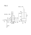
- FIG. 2 is a schematic circuit diagram showing a state in which compressed air is supplied to the second internal chamber of the pneumatic cylinder and compressed air is discharged from the first internal chamber of the pneumatic cylinder.
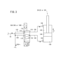
- FIG. 3 is a schematic circuit diagram showing a state in which compressed air is supplied to the first internal chamber of the pneumatic cylinder and compressed air is discharged from the second internal chamber of the pneumatic cylinder.
- FIG. 4 is a schematic explanatory diagram showing a state in which fluorescence is emitted from the inspected portion of the pipe.
- FIG. 5 is a schematic explanatory diagram showing a state in which fluorescence is emitted from one pneumatic cylinder (or one pipe joint).
- leak point in the following description means the point where compressed air leaks.
- upstream represents the upstream in the direction of circulation of compressed air.
- downstream represents downstream in the direction of flow of compressed air.
- FIG. 1 is a schematic circuit diagram of the pneumatic equipment system 10.
- the pneumatic system 10 has a compressor 12 and a main line 14 connected to the compressor 12 .
- the compressor 12 generates compressed air by sucking and compressing atmospheric air.
- a plurality of first sub-pipes 16 are connected to the main pipe 14 .
- a plurality of (three in the present embodiment) second sub-pipes 18 are connected to one first sub-pipe 16 .
- a first pneumatic cylinder 20, a second pneumatic cylinder 22 and a third pneumatic cylinder 24 are connected to each of the second sub pipes 18, respectively.
- the first to third pneumatic cylinders 20, 22, 24 are one type of pneumatic equipment. Compressed air obtained by the compressor 12 flows through the main pipe 14 , the first sub-pipe 16 and the second sub-pipe 18 . Compressed air is supplied to the first through third pneumatic cylinders 20, 22, 24 individually.
- the first to third pneumatic cylinders 20, 22, 24 operate individually using this compressed air as working air.
- a pipe inspection system 30 is incorporated in the first sub pipe 16 .
- the pipe inspection system 30 is a system for inspecting whether or not there is a leak in the inspected portion 32 of the first sub-pipe 16 .
- the piping inspection system 30 has a first branch pipe 34 .
- the upstream of the first branch pipe 34 branches off from the first sub pipe 16 upstream of the inspected portion 32 .
- the downstream of the first branch pipe 34 joins the first sub pipe 16 .
- the confluence point of the first branch pipe 34 and the first sub pipe 16 is downstream of the branch point of the first branch pipe 34 and upstream of the inspected portion 32 .
- a first valve 36 is provided upstream of the inspected portion 32 in the first sub pipe 16 .
- the first valve 36 is positioned in the first sub pipe 16 between the branch point of the first branch pipe 34 and the joining point.
- a second valve 38 is provided on the first branch pipe 34 .
- the first valve 36 When the first valve 36 is open and the second valve 38 is closed, compressed air flows through the first subsidiary pipe 16 and does not flow through the first branch pipe 34 . Conversely, when the first valve 36 is closed and the second valve 38 is open, compressed air flows through the first branch pipe 34 and not through the first sub pipe 16 .
- a first fluorescent solvent supply unit 40 is provided downstream of the second valve 38 in the first branch pipe 34 .
- the first fluorescent solvent supply 40 has a first mist generator 42 .
- a specific example of the first mist generator 42 is a lubricator.
- a lubricator is known as a container that contains lubricating oil.
- a known bubbler can be used as the first mist generator 42 .
- a first fluorescent solvent 44 is contained in the first mist generator 42 .
- the first fluorescent solvent 44 is obtained by diluting a fluorescent agent with a solvent.
- the solvent of the first fluorescence solvent 44 is, for example, water.
- the first fluorescent solvent 44 is an aqueous solution of fluorescent agent.
- the solvent may be water to which oil has been added.
- the first fluorescent solvent 44 is an aqueous emulsion of a fluorescent agent.
- fluorescent agents include coumarin, vitamin B2, and the like.
- compressed air flows through the first branch pipe 34 .
- the first fluorescent solvent 44 is misted. That is, mist of the first fluorescent solvent 44 is generated.
- the mist circulates through the first branch pipe 34 and moves to the inspected portion 32 of the first sub pipe 16 .
- the piping inspection system 30 has a second branch pipe 46 .
- the upstream of the second branch pipe 46 branches off from the first sub pipe 16 downstream of the inspected portion 32 .
- the downstream of the second branch pipe 46 merges with the first sub pipe 16 .
- the confluence point of the second branch pipe 46 and the first sub pipe 16 is downstream of the branch point of the second branch pipe 46 and downstream of the inspected portion 32 .
- a third valve 48 is provided downstream of the inspected portion 32 in the first sub pipe 16 .
- the third valve 48 is located in the first sub pipe 16 between the branch point of the second branch pipe 46 and the joining point.
- a fourth valve 50 is provided on the second branch pipe 46 .
- the third valve 48 When the third valve 48 is open and the fourth valve 50 is closed, compressed air flows through the first subsidiary pipe 16 and does not flow through the second branch pipe 46 . Conversely, when the third valve 48 is closed and the fourth valve 50 is open, compressed air flows through the second branch pipe 46 and not through the first subsidiary pipe 16 .
- a first fluorescent solvent recovery unit 52 is provided downstream of the fourth valve 50 in the second branch pipe 46 .
- the first fluorescent solvent recovery section 52 has a first filter 54 .
- the first filter 54 removes the first fluorescent solvent 44 (mist) contained in the compressed air from the compressed air. Therefore, compressed air containing no mist flows downstream of the first filter 54 .
- a first exhaust pipe 56 (exhaust portion) branches from the second branch pipe 46 downstream of the first filter 54 in the second branch pipe 46 .
- a fifth valve 58 is provided at the end of the first exhaust pipe 56 .
- An outlet port of the fifth valve 58 is open to the atmosphere via a first silencer 60 .
- the first to fifth valves 36, 38, 48, 50, 58 are, for example, automatic on-off valves.
- the first to fifth valves 36, 38, 48, 50, 58 may be manual open/close valves.
- the piping inspection system 30 includes a first black light 62.
- the first black light 62 is supported by, for example, a pedestal (not shown).
- the pedestal is provided with casters (not shown). Therefore, the pedestal and the first black light 62 can be moved by rolling the casters.
- the first black light 62 approaches or separates from the inspected portion 32 .
- the first black light 62 irradiates the inspected portion 32 with ultraviolet rays.
- the compressed air and fluorescent solvent (mist) are jetted out from the leak point.
- UV light illuminates the fluorescent solvent, an enhanced fluorescence F is observed, as shown schematically in FIG.
- a regulator 64 is provided in the first sub pipe 16 downstream of the junction of the second branch pipes 46 .
- a device inspection system 70 is incorporated downstream of the regulator 64 in the first sub pipe 16 .
- the equipment inspection system 70 inspects the first sub pipe 16 to which the first to third pneumatic cylinders 20, 22, 24 or the pipe joints 128, 130 in which the compressed air is leaking is connected. It is a system to specify from among 16.
- the equipment inspection system 70 is also a system that identifies from which of the first to third pneumatic cylinders 20, 22, 24 or the pipe joints 128, 130 the compressed air is leaking.
- the equipment inspection system 70 has a first branch pipe 72 .
- the upstream of the first branch pipe 72 branches off from the first sub pipe 16 .
- the downstream of the first branch pipe 72 joins the first sub pipe 16 .
- the confluence point of the first branch pipe 72 and the first sub pipe 16 is downstream of the branching point of the first branch pipe 72 and upstream of the second sub pipe 18 .
- a first electromagnetic valve 74 is provided in the first sub pipe 16 downstream of the branching point of the first branch pipe 72 .
- a second electromagnetic valve 76 is provided on the first branch pipe 72 .
- the first solenoid valve 74 When the first solenoid valve 74 is open and the second solenoid valve 76 is closed, compressed air flows through the first sub pipe 16 and does not flow through the first branch pipe 72 . Conversely, when the first solenoid valve 74 is closed and the second solenoid valve 76 is open, compressed air flows through the first branch pipe 72 and through the first sub pipe 16. do not.
- a second fluorescent solvent supply unit 78 is provided downstream of the second electromagnetic valve 76 in the first branch pipe 72 . Similar to the first fluorescent solvent supply 40 , the second fluorescent solvent supply 78 has a second mist generator 80 .
- a specific example of the second mist generator 80 is a lubricator or a bubbler like the first mist generator 42 .
- a second fluorescent solvent 82 is contained in the second mist generator 80 .
- the second fluorescent solvent 82 is obtained by diluting the above-described fluorescent agent with a solvent.
- the solvent of the second fluorescent solvent 82 is, for example, a highly volatile organic solvent.
- the organic solvent may be diluted alcohols. Specific examples of alcohols include ethanol.
- the second fluorescent solvent 82 is an ethanol solution of a fluorescent agent.
- compressed air flows through the first branch pipe 72 .
- the second fluorescent solvent 82 is misted. That is, mist of the second fluorescent solvent 82 is generated.
- the mist of the second fluorescent solvent 82 flows through the first branch pipe 72 and moves to the first sub pipe 16 .
- a second exhaust pipe 84 is provided in the first branch pipe 72 .
- a second fluorescent solvent recovery section 86 is provided in the second exhaust pipe 84 .
- the second fluorescent solvent recovery section 86 has a second filter 88 .
- a second filter 88 removes the second fluorescent solvent 82 (mist) contained in the compressed air from the compressed air. Therefore, in the second exhaust pipe 84 , compressed air containing no mist flows downstream of the second filter 88 .
- a sixth valve 90 is provided at the end of the second exhaust pipe 84 .
- the sixth valve 90 is an automatic on-off valve or a manual on-off valve.
- An outlet port of the sixth valve 90 is open to the atmosphere via a second silencer 92 .
- the equipment inspection system 70 has a second branch pipe 94 .
- the upstream of the second branch pipe 94 branches off from the first sub pipe 16 .
- the downstream of the second branch pipe 94 merges with the first sub pipe 16 .
- the confluence point of the second branch pipe 94 and the first sub pipe 16 is downstream of the branch point of the second branch pipe 94 and upstream of the second sub pipe 18 .
- a third solenoid valve 96 and a digital flow switch 98 are provided on the second branch pipe 94 .
- a third solenoid valve 96 is located upstream of the digital flow switch 98 .
- a digital flow switch 98 measures the flow rate of compressed air flowing through the second branch pipe 94 .
- digital flow switch 98 is a flow meter.
- Digital flow switch 98 also functions as a flow control valve.
- the first solenoid valve 74 , the second solenoid valve 76 and the third solenoid valve 96 are electrically connected to the valve control device 100 .
- the valve control device 100 controls the first solenoid valve 74 , the second solenoid valve 76 and the third solenoid valve 96 to open and close the first solenoid valve 74 , the second solenoid valve 76 and the third solenoid valve 96 . That is, the first solenoid valve 74 , the second solenoid valve 76 and the third solenoid valve 96 are automatically opened and closed by the valve control device 100 .
- the digital flow switch 98 is also electrically connected to a personal computer (PC) 102 .
- a digital flow switch 98 measures the flow rate of the compressed air flowing through the second branch pipe 94 .
- PC 102 records the measured flow rate. That is, the PC 102 is a storage device.
- FIG. 1 illustrates a case where three second sub-pipes 18 branch from one first sub-pipe 16 .
- a fourth solenoid valve 104, a fifth solenoid valve 106, and a sixth solenoid valve 108 are provided in the three second sub pipes 18, respectively.
- the number of second sub pipes 18 is not particularly limited to three.
- the number of solenoid valves is typically the same as the number of second sub pipes 18 .
- the fourth solenoid valve 104 has a first port 110, a second port 112, a third port 114, a fourth port 116 and a fifth port 118.
- a first discharge pipe 120 is connected to the first port 110 .
- a second sub pipe 18 is connected to the second port 112 .
- a second discharge pipe 122 is connected to the third port 114 .
- a first connection pipe 124 is connected to the fourth port 116 .
- a second connection pipe 126 is connected to the fifth port 118 .
- the first connection pipe 124 connects the fourth solenoid valve 104 and the first pneumatic cylinder 20 via a first pipe joint 128 .
- the second connecting pipe 126 connects the fourth solenoid valve 104 and the first pneumatic cylinder 20 via the second pipe joint 130 .
- a first inner chamber 140 and a second inner chamber 142 are formed inside the first pneumatic cylinder 20 . Compressed air is supplied to or exhausted from the first inner chamber 140 via the first connecting pipe 124 . Compressed air is supplied to or exhausted from the second inner chamber 142 via the second connecting pipe 126 .
- FIG. 2 shows a case where compressed air is supplied to the second internal chamber 142 and compressed air is discharged from the first internal chamber 140 .
- the compressed air that has flowed through the second sub pipe 18 moves from the second port 112 to the fifth port 118 inside the fourth solenoid valve 104 .
- the compressed air then flows through the second connecting tube 126 via the fifth port 118 and into the second inner chamber 142 .
- Compressed air in the second inner chamber 142 pushes the piston 144 in the direction of the arrow X.
- piston 144 moves in the direction of arrow X in FIG.
- the compressed air in the first inner chamber 140 is pushed out to the first connecting pipe 124 by the piston 144 .
- Compressed air then travels through the fourth solenoid valve 104 from the fourth port 116 to the first port 110 .
- the compressed air is discharged through the first port 110 to the first discharge pipe 120 .
- the third port 114 is closed.
- the compressed air inside the second inner chamber 142 is pushed out to the second connecting pipe 126 by the piston 144 .
- Compressed air then travels through the fourth solenoid valve 104 from the fifth port 118 to the third port 114 .
- the compressed air is discharged to the second discharge pipe 122 via the third port 114 .
- the first port 110 is closed.
- All the first exhaust pipes 120 and all the second exhaust pipes 122 are connected to one third exhaust pipe 150 (exhaust section).
- a third fluorescent solvent recovery section 152 is provided in the third exhaust pipe 150 .
- the third fluorescent solvent recovery section 152 has a third filter 154 .
- the third filter 154 like the first filter 54 and the second filter 88, removes the second fluorescent solvent 82 (mist) contained in the compressed air from the compressed air. Accordingly, compressed air containing no mist flows downstream of the third filter 154 .
- a portion of the third exhaust pipe 150 downstream of the third filter 154 is open to the atmosphere via a third silencer 156 .
- the equipment inspection system 70 includes a second black light 158.
- the second black light 158 is supported by, for example, a pedestal (not shown).
- the pedestal is provided with casters (not shown). Therefore, the pedestal and the second black light 158 can be moved by rolling the casters.
- the second black light 158 moves toward or away from the first through third pneumatic cylinders 20,22,24.
- the second black light 158 irradiates the first to third pneumatic cylinders 20, 22, 24 and their surroundings with ultraviolet rays.
- the first pipe joint 128 or the second pipe joint 130 as schematically shown in FIG. Compressed air and fluorescent solvent (mist) are ejected.
- UV light illuminates the fluorescent solvent, an enhanced fluorescence F is observed.
- first sub-pipe 16 and the second sub-pipe 18 are shown as linear seamless pipes for easy understanding.
- first sub-pipe 16 and the second sub-pipe 18 are not limited to linear seamless pipes.
- first sub-pipe 16 and the second sub-pipe 18 may be seamless pipes bent at a predetermined angle.
- the first sub-pipe 16 and the second sub-pipe 18 may be connecting pipes in which a plurality of seamless pipes are connected via pipe joints.
- the pneumatic equipment system 10 including the piping inspection system 30 and the equipment inspection system 70 is basically configured as described above.
- the leak test method has the steps detailed below.
- the leakage inspection method includes a leakage inspection method for pipes and equipment.
- the leak inspection of the piping and the leak inspection of the pneumatic equipment are performed, for example, before the operation of the pneumatic equipment system 10 is started. This case will be described below as an example.
- the inspected portion 32 is irradiated with ultraviolet rays from the first black light 62 .
- the first valve 36 and the third valve 48 provided on the first sub pipe 16 are closed. In this state, compressed air is supplied from the compressor 12 to the main pipe 14 . Compressed air is distributed to each of the plurality of first sub-pipes 16 . Since the first valve 36 is closed, compressed air is prevented from flowing downstream of the first valve 36 in the first sub-pipe 16 .
- the second valve 38 and the fourth valve 50 are opened.
- the second valve 38 and the fourth valve 50 may be opened before supplying compressed air from the compressor 12 to the main pipe 14 . If necessary, the fifth valve 58 is also opened.
- Compressed air flows through the first branch pipe 34 by opening the second valve 38 . Compressed air is discharged toward the first fluorescent solvent 44 within the first mist generator 42 . As a result, a mist of the first fluorescent solvent 44 is generated. Accompanied by compressed air, the mist flows through the first branch pipe 34 and then flows into the inspected portion 32 of the first sub pipe 16 .
- the solvent of the first fluorescence solvent 44 is water, an aqueous emulsion solution, or the like.
- the vapor pressure of water or an aqueous emulsion solution is relatively low.
- the first sub pipe 16, the first branch pipe 34, the second branch pipe 46, the first mist generator 42, the first filter 54, etc. are made to have a pressure-resistant structure in consideration of the vapor pressure when the mist evaporates. No need.
- a first fluorescent solvent recovery part 52 is provided in the second branch pipe 46 .
- the first fluorescent solvent recovery section 52 has a first filter 54 .
- Mist (first fluorescent solvent 44 ) contained in the compressed air is collected by first filter 54 . This collection removes mist from the compressed air.
- the compressed air from which mist has been removed flows into the first exhaust pipe 56 .
- the fifth valve 58 When the fifth valve 58 is open, compressed air is released from the fifth valve 58 through the first silencer 60 to the atmosphere.
- the compressed air from which mist has been removed returns to the first sub pipe 16 via the second branch pipe 46 .
- the point where the compressed air returns to the first sub-pipe 16 is downstream of the third valve 48 in the first sub-pipe 16 .
- the compressed air is then supplied to instrument inspection system 70 . Since mist is removed from the compressed air, the concern that water, which is a solvent, flows into the first to sixth solenoid valves 74 to 108 or the first to third pneumatic cylinders 20, 22, 24, etc., is eliminated. . Therefore, corrosion of the first to sixth solenoid valves 74 to 108 or the first to third pneumatic cylinders 20, 22, 24 is avoided.
- the leak location may be, for example, a hole, a crack, or insufficient tightening of a pipe joint.
- compressed air and mist first fluorescent solvent 44
- the mist contains fluorescent agents. When the fluorescent agent is irradiated with ultraviolet light, an enhanced fluorescence F is observed as shown in FIG. The inspector can recognize that the compressed air is leaking based on the fluorescence F being observed.
- the fluorescence F is radially diffused from one point.
- the starting point of diffusion of the fluorescence F is the leak point. In this way, by examining the starting point of diffusion of the fluorescence F, it is possible to easily identify the leakage point in a short time.
- fluorescence F is observed even when the amount of compressed air leakage is very small. Therefore, for example, even if the leak location is a minute hole, the inspector can detect the leak location without overlooking it. Moreover, it is not necessary for the inspector to have special knowledge or the like to determine the presence or absence of the leakage point. Likewise, the inspector does not need to have special knowledge or the like to identify the leak location.
- the inspector can quickly determine whether or not there is a leak location based on whether or not the fluorescence F is generated. In other words, the inspector can easily determine the presence or absence of leakage regardless of the degree of skill or the degree of acquired knowledge. It is also easy for an inspector to identify the leak location.
- the equipment inspection system 70 inspects the first to third pneumatic cylinders 20, 22, 24 (and the pipe joints 128, 130) for leakage.
- the fifth valve 58 is closed, and the compressed air that has flowed through the first branch pipe 34, the inspected portion 32, and the second branch pipe 46 as described above is applied to the first to third air pressures via the regulator 64. Cylinders 20, 22, 24 are fed.
- the leakage inspection of the piping (inspected portion 32) and the leakage inspection of the first to third pneumatic cylinders 20, 22, 24 (and the pipe joints 128, 130) can be performed at the same time.
- first valve 36 and the third valve 48 are switched to the open state, and the second valve 38 and the fourth valve 50 are switched to the closed state.
- the compressed air does not flow through the first branch pipe 34 and the second branch pipe 46, but flows only through the first sub pipe 16.
- This compressed air passes through a regulator 64 and is supplied to the first to third pneumatic cylinders 20 , 22 , 24 .
- the valve control device 100 controls the first to third solenoid valves 74, 76, 96 to close the first solenoid valve 74 and the second solenoid valve 76 and to open the third solenoid valve 96. .
- compressed air that has passed through the regulator 64 flows only into the second branch pipe 94 .
- a digital flow switch 98 measures the flow rate of compressed air flowing through the second branch pipe 94 and converts the flow rate into an information signal.
- PC 102 records the information signal as flow rate.
- the display of the PC 102 displays a graph with elapsed time on the horizontal axis and flow rate on the vertical axis.
- the compressed air that has flowed through the second branch pipe 94 flows into each of the plurality of second sub pipes 18 .
- Compressed air passes through the fourth solenoid valve 104, the fifth solenoid valve 106 and the sixth solenoid valve 108 and is introduced from the second connecting pipe 126 into the second inner chambers 142 of the first to third pneumatic cylinders 20, 22 and 24. (See FIG. 2). Accordingly, the piston 144 moves in the X direction.
- Compressed air in the first inner chamber 140 passes through the first connecting pipe 124 and the fourth solenoid valve 104 , the fifth solenoid valve 106 and the sixth solenoid valve 108 .
- the compressed air in the first inner chamber 140 passes through the first exhaust pipe 120 and then is released to the atmosphere from the third exhaust pipe 150 via the third silencer 156 .
- the flow rate of the compressed air in the second branch pipe 94 is A value greater than zero. The inspector can recognize that the flow rate of compressed air in the second branch pipe 94 is greater than zero by checking the display of the digital flow switch 98 or the display of the PC 102 .
- the inspector determines that any one of the first through third pneumatic cylinders 20, 22, 24 (or fittings 128, 130) should operate based on the fact that the flow rate of compressed air in the second branch 94 is greater than zero. It can be determined that there is a leakage point at some point. The inspector then proceeds to identify which of the first to third pneumatic cylinders 20, 22, 24 (or pipe joints 128, 130) is leaking.
- the inspector While maintaining the closed state of the first electromagnetic valve 74, the inspector operates the valve control device 100 to switch the second electromagnetic valve 76 to the closed state. Also, the inspector operates the valve control device 100 to switch the third electromagnetic valve 96 to the open state. Compressed air circulates only through the first branch pipe 72 by the above operation. Further, the periphery of the first to third pneumatic cylinders 20 , 22 , 24 is irradiated with ultraviolet rays from the second black light 158 .
- the compressed air flowing through the first branch pipe 72 is discharged toward the second fluorescent solvent 82 inside the second mist generator 80 .
- a mist of the second fluorescent solvent 82 is generated.
- the mist flows through the first branch pipe 72 accompanied by compressed air, it passes through the first sub pipe 16 and is distributed to each of the plurality of second sub pipes 18 .
- the compressed air with mist then passes through the fourth to sixth solenoid valves 104 to 108, respectively, and is supplied to the first to third pneumatic cylinders 20, 22, 24, respectively.
- the first chamber 140 (or second chamber 142) is first supplied with compressed air and the second chamber 142 (or first chamber 140) is exhausted. After a predetermined time has passed, the supply destination of the compressed air is switched. That is, it supplies compressed air to the second internal chamber 142 (or first internal chamber 140) and exhausts compressed air from the first internal chamber 140 (or second internal chamber 142).
- first pneumatic cylinder 20 When compressed air is supplied to the second inner chamber 142 , the compressed air in the first inner chamber 140 flows through the first connecting pipe 124 , the fourth port 116 of the fourth solenoid valve 104 , the fourth port 116 of the fourth solenoid valve 104 , and the 1 port 110, the first exhaust pipe 120, and the third exhaust pipe 150 (see FIG. 2). Conversely, when compressed air is supplied to the first inner chamber 140, the compressed air in the second inner chamber 142 flows through the second connecting pipe 126, the fifth port 118 of the fourth solenoid valve 104, and the fourth solenoid valve. 104, the third port 114, the second exhaust pipe 122, and the third exhaust pipe 150 (see FIG. 3).
- the compressed air passes through the fifth solenoid valve 106 instead of the fourth solenoid valve 104 .
- the compressed air passes through the sixth solenoid valve 108 instead of the fourth solenoid valve 104 .
- a third fluorescent solvent recovery part 152 is provided in the third exhaust pipe 150 .
- the third fluorescent solvent recovery section 152 has a third filter 154 .
- Mist (the second fluorescent solvent 82 ) contained in the compressed air is collected by the third filter 154 . This collection removes mist from the compressed air.
- the compressed air from which mist has been removed is discharged to the atmosphere from the third exhaust pipe 150 via the third silencer 156 .
- the equipment inspection system 70 first, from among the plurality of first sub pipes 16, the first to third pneumatic cylinders 20, 22, 24 ( Alternatively, the first sub pipe 16 to which the pipe joints 128, 130) are connected is identified. In this case, only the first to third pneumatic cylinders 20, 22, 24 that are determined to have leakage and their surroundings are irradiated with ultraviolet rays. Next, based on the fluorescence F being emphasized by the ultraviolet rays, the pneumatic cylinders (or pipe joints) in which leakage is occurring from among the first to third pneumatic cylinders 20, 22, 24 (or pipe joints 128, 130) 128, 130) are identified.
- first to third pneumatic cylinders 20, 22, 24 or the pipe joints 128, 130
- other first sub-pipe 16 is the first sub-pipe 16 whose flow rate measured by the digital flow switch 98 is zero.
- the inspector may use compressed air from the first to third pneumatic cylinders 20, 22, 24 (or pipe joints 128, 130). is leaking. Also, the inspector can easily identify the leak location in a short period of time.
- Compressed air containing mist of the second fluorescent solvent 82 flows through the fourth electromagnetic valve 104 to the sixth electromagnetic valve 108 and the first to third pneumatic cylinders 20, 22, 24, and the like.
- the solvent of the second fluorescent solvent 82 is, for example, a highly volatile organic solvent.
- the mist evaporates quickly. Therefore, mist hardly stays inside the second sub pipe 18, the fourth to sixth solenoid valves 104 to 108, the first to third pneumatic cylinders 20, 22, 24, and the like. Therefore, failure or corrosion of the fourth to sixth solenoid valves 104 to 108 and the first to third pneumatic cylinders 20, 22, 24 due to the mist of the second fluorescent solvent 82 is avoided. .
- the lubricant (grease, etc.) in the fourth to sixth solenoid valves 104 to 108 and the first to third pneumatic cylinders 20, 22, 24 is almost always eluted into the mist. do not have. Therefore, it is avoided that the fourth to sixth solenoid valves 104 to 108 and the first to third pneumatic cylinders 20, 22, 24 are not affected in their sealing or operating performance.
- the main materials of the fourth to sixth solenoid valves 104 to 108 and the first to third pneumatic cylinders 20, 22, 24 are metal materials. Metal materials are chemically stable against organic solvents. Therefore, if the solvent of the second fluorescent solvent 82 is an organic solvent, failure or corrosion may occur in the fourth to sixth solenoid valves 104 to 108 and the first to third pneumatic cylinders 20, 22, 24, etc. further avoided.
- the solvent of the second fluorescent solvent 82 is preferably alcohol such as ethanol.
- the fourth electromagnetic valve 104 to sixth electromagnetic valve 108 and the first to third pneumatic cylinders 20, 22, 24, etc. have a pressure-resistant structure. Therefore, even when the mist evaporates, there is no concern that the fourth to sixth solenoid valves 104 to 108 and the first to third pneumatic cylinders 20, 22, 24, etc. will be deformed by the vapor pressure.
- the inspected portion 32 or the device that is determined to have a leak location is replaced.
- the leak test is then repeated until no leaks are found.
- the fifth valve 58 is opened. Along with this, mist and compressed air are released from the first branch pipe 72 to the atmosphere via the second silencer 92 . Therefore, the stagnation of mist in the first branch pipe 72 is avoided.
- the first valve 36, the third valve 48 and the first solenoid valve 74 are opened, and the second valve 38, the fourth valve 50, the fifth valve 58 and the second solenoid valve 76 are opened. and the third electromagnetic valve 96 are closed. Compressed air leaving the compressor 12 is thereby distributed to each first sub-pipe 16 via the main pipe 14 . The compressed air is then distributed to each second sub-pipe 18 and becomes working air for operating the first through third pneumatic cylinders 20,22,24. At this time, compressed air does not flow through the first branch pipe 34 and the first branch pipe 72 . Therefore, the mist does not flow together with the compressed air.
- the inspector can determine in a short time whether or not there is a leakage point based on whether or not the fluorescence F is generated. Therefore, for example, when compressed air leaks due to unforeseen circumstances during operation of the pneumatic equipment system 10, the operation of the pneumatic equipment system 10 can be stopped and the leak inspection of the pipes or equipment can be completed in a short time. can. In other words, the pneumatic system 10 does not need to be stopped for an extended period of time. Therefore, it is possible to restore the pneumatic equipment system 10 early.
- the present embodiment is a pipe inspection system (30) for inspecting whether or not there is a leak of compressed air in the inspected portion (32) of the pipe (16) through which compressed air flows.
- a first branch pipe (34) branching from the pipe upstream of the inspected portion and joining the pipe;
- a fluorescent solvent supply unit (40) provided in the first branch pipe for supplying a fluorescent solvent (44) to the inspected portion;
- a second branch pipe (46) branching from the pipe downstream of the inspected portion;
- a fluorescent solvent recovery unit (52) provided in the second branch pipe for recovering the fluorescent solvent from the inspected portion;
- the fluorescent solvent is recovered by the fluorescent solvent recovery section after it circulates through the part to be inspected. Therefore, the fluorescent solvent is prevented from flowing downstream of the portion of the pipe to be inspected. That is, the fluorescent solvent is prevented from flowing into the pneumatic equipment or the like connected to the end of the pipe. Moreover, it is also avoided that the fluorescent solvent stays inside the piping or the pneumatic equipment. Therefore, the concern that the pneumatic equipment will malfunction or corrode due to the fluorescent solvent will be eliminated.
- the present embodiment discloses a pipe inspection system in which the fluorescent solvent supply unit has a mist generator (42) that turns the fluorescent solvent into mist, and supplies the fluorescent solvent in the mist state to the inspected portion.
- This embodiment discloses a pipe inspection system in which the fluorescent solvent is an aqueous solution or aqueous emulsion of a fluorescent agent.
- the vapor pressure of water or emulsion water is relatively low. Therefore, it is not easy for the mist to evaporate inside the piping. Therefore, it is not particularly necessary to make the piping inspection system a pressure-resistant structure in consideration of the vapor pressure of the mist. Therefore, it is possible to reduce the cost of equipment investment.
- a first valve (36) provided between a location where the first branch pipe branches and a location where the first branch pipe joins, and a fluorescent solvent supply portion of the first branch pipe
- a second valve (38) provided upstream of the pipe
- a third valve (48) provided downstream of the location where the second branch pipe branches
- the opening and closing of the first to fourth valves can be switched individually.
- the fluid flowing through the inspected portion can be selectively switched to either compressed air containing no mist or compressed air accompanied by mist. That is, it is easy to switch the fluid flowing through the inspected portion.
- This embodiment discloses a pipe inspection system provided with an exhaust section (56) that is provided downstream of the fluorescent solvent recovery section of the second branch pipe and is open to the atmosphere.
- the fluorescent solvent accompanying the compressed air is separated from the compressed air by the fluorescent solvent recovery unit. Therefore, compressed air from which the fluorescent solvent has been removed flows downstream of the fluorescent solvent collecting section.
- compressed air can be released to the atmosphere in such a situation. Therefore, it is possible to prevent the fluorescent solvent from flowing into the pneumatic equipment or the like connected to the end of the pipe.
- This embodiment discloses a pipe inspection system that includes a black light (62) that irradiates ultraviolet light onto the inspected portion.
- the size of the black light is sufficient to irradiate the portion to be inspected with ultraviolet rays. Therefore, it is possible to reduce the cost of equipment investment.
- the pneumatic equipment is not particularly limited to pneumatic cylinders.
- Other specific examples of pneumatic devices include pneumatic chucks and pneumatic actuators.
Landscapes
- Physics & Mathematics (AREA)
- General Physics & Mathematics (AREA)
- Examining Or Testing Airtightness (AREA)
Abstract
Description
前記被検査部分の上流で前記配管から分岐し、且つ前記配管に合流する第1分岐管と、
前記第1分岐管に設けられて前記被検査部分に蛍光溶剤を供給する蛍光溶剤供給部と、
前記被検査部分の下流で前記配管から分岐する第2分岐管と、
前記第2分岐管に設けられて前記被検査部分から前記蛍光溶剤を回収する蛍光溶剤回収部と、
を備える配管検査システムが提供される。 According to one embodiment of the present invention, a piping inspection system for inspecting whether or not a compressed air leakage point exists in an inspected portion of a piping through which compressed air flows,
a first branch pipe branching from the pipe upstream of the inspected portion and joining the pipe;
a fluorescent solvent supply unit provided in the first branch pipe for supplying the fluorescent solvent to the inspected portion;
a second branch pipe branching from the pipe downstream of the inspected portion;
a fluorescent solvent recovery unit provided in the second branch pipe for recovering the fluorescent solvent from the inspected portion;
A piping inspection system is provided comprising:
前記被検査部分の上流で前記配管から分岐し、且つ前記配管に合流する第1分岐管(34)と、
前記第1分岐管に設けられて前記被検査部分に蛍光溶剤(44)を供給する蛍光溶剤供給部(40)と、
前記被検査部分の下流で前記配管から分岐する第2分岐管(46)と、
前記第2分岐管に設けられて前記被検査部分から前記蛍光溶剤を回収する蛍光溶剤回収部(52)と、
を備える配管検査システムを開示する。 As described above, the present embodiment is a pipe inspection system (30) for inspecting whether or not there is a leak of compressed air in the inspected portion (32) of the pipe (16) through which compressed air flows. hand,
a first branch pipe (34) branching from the pipe upstream of the inspected portion and joining the pipe;
a fluorescent solvent supply unit (40) provided in the first branch pipe for supplying a fluorescent solvent (44) to the inspected portion;
a second branch pipe (46) branching from the pipe downstream of the inspected portion;
a fluorescent solvent recovery unit (52) provided in the second branch pipe for recovering the fluorescent solvent from the inspected portion;
A pipe inspection system is disclosed.
Claims (6)
- 圧縮エアが流通する配管(16)の被検査部分(32)に圧縮エアの漏洩箇所が存在するか否かを検査する配管検査システム(30)であって、
前記被検査部分の上流で前記配管から分岐し、且つ前記配管に合流する第1分岐管(34)と、
前記第1分岐管に設けられて前記被検査部分に蛍光溶剤(44)を供給する蛍光溶剤供給部(40)と、
前記被検査部分の下流で前記配管から分岐する第2分岐管(46)と、
前記第2分岐管に設けられて前記被検査部分から前記蛍光溶剤を回収する蛍光溶剤回収部(52)と、
を備える配管検査システム。 A pipe inspection system (30) for inspecting whether or not there is a compressed air leakage point in an inspected portion (32) of a pipe (16) through which compressed air flows,
a first branch pipe (34) branching from the pipe upstream of the inspected portion and joining the pipe;
a fluorescent solvent supply unit (40) provided in the first branch pipe for supplying a fluorescent solvent (44) to the inspected portion;
a second branch pipe (46) branching from the pipe downstream of the inspected portion;
a fluorescent solvent recovery unit (52) provided in the second branch pipe for recovering the fluorescent solvent from the inspected portion;
A piping inspection system comprising: - 請求項1記載の配管検査システムにおいて、前記蛍光溶剤供給部は、蛍光溶剤をミスト化するミスト発生器(42)を有し、ミストとなった蛍光溶剤を前記被検査部分に供給する配管検査システム。 2. The pipe inspection system according to claim 1, wherein the fluorescent solvent supply unit has a mist generator (42) for turning the fluorescent solvent into a mist, and supplies the fluorescent solvent in the mist form to the portion to be inspected. .
- 請求項1又は2記載の配管検査システムにおいて、前記蛍光溶剤が、蛍光剤の水溶液又はエマルジョン水溶液である配管検査システム。 The pipe inspection system according to claim 1 or 2, wherein the fluorescent solvent is an aqueous solution or aqueous emulsion solution of a fluorescent agent.
- 請求項1記載の配管検査システムにおいて、前記配管の、前記第1分岐管が分岐する箇所から合流する箇所までの間に設けられた第1弁(36)と、前記第1分岐管の、前記蛍光溶剤供給部よりも上流に設けられた第2弁(38)と、前記配管の、前記第2分岐管が分岐する箇所よりも下流に設けられた第3弁(48)と、前記第2分岐管の、前記蛍光溶剤回収部よりも上流に設けられた第4弁(50)とを備える配管検査システム。 2. The pipe inspection system according to claim 1, wherein a first valve (36) is provided between a location where said first branch pipe branches and a location where said first branch pipe joins, and said first branch pipe, said A second valve (38) provided upstream of the fluorescent solvent supply section, a third valve (48) provided downstream of the branching point of the second branch pipe of the pipe, and the second A pipe inspection system comprising a fourth valve (50) provided upstream of the fluorescent solvent recovery section of the branch pipe.
- 請求項1~4のいずれか1項に記載の配管検査システムにおいて、前記第2分岐管の、前記蛍光溶剤回収部よりも下流に設けられ、大気に開放された排気部(56)を備える配管検査システム。 The pipe inspection system according to any one of claims 1 to 4, wherein the second branch pipe is provided downstream of the fluorescent solvent recovery part and is provided with an exhaust part (56) open to the atmosphere. inspection system.
- 請求項1記載の配管検査システムにおいて、前記被検査部分に紫外線を照射するブラックライト(62)を備える配管検査システム。 The pipe inspection system according to claim 1, comprising a black light (62) for irradiating ultraviolet rays onto said portion to be inspected.
Priority Applications (3)
| Application Number | Priority Date | Filing Date | Title |
|---|---|---|---|
| KR1020247011734A KR20240054367A (en) | 2021-09-09 | 2022-07-11 | plumbing inspection system |
| CN202280061219.5A CN117957430A (en) | 2021-09-09 | 2022-07-11 | Piping inspection system |
| EP22865920.7A EP4382880A1 (en) | 2021-09-09 | 2022-07-11 | Pipe inspection system |
Applications Claiming Priority (2)
| Application Number | Priority Date | Filing Date | Title |
|---|---|---|---|
| JP2021146893A JP2023039661A (en) | 2021-09-09 | 2021-09-09 | Piping inspection system |
| JP2021-146893 | 2021-09-09 |
Publications (1)
| Publication Number | Publication Date |
|---|---|
| WO2023037753A1 true WO2023037753A1 (en) | 2023-03-16 |
Family
ID=85506488
Family Applications (1)
| Application Number | Title | Priority Date | Filing Date |
|---|---|---|---|
| PCT/JP2022/027221 WO2023037753A1 (en) | 2021-09-09 | 2022-07-11 | Pipe inspection system |
Country Status (6)
| Country | Link |
|---|---|
| EP (1) | EP4382880A1 (en) |
| JP (1) | JP2023039661A (en) |
| KR (1) | KR20240054367A (en) |
| CN (1) | CN117957430A (en) |
| TW (1) | TW202314213A (en) |
| WO (1) | WO2023037753A1 (en) |
Citations (4)
| Publication number | Priority date | Publication date | Assignee | Title |
|---|---|---|---|---|
| JPS6189533A (en) * | 1984-10-08 | 1986-05-07 | Mitsubishi Heavy Ind Ltd | Method for testing atmospheric pressure |
| JP2006126050A (en) * | 2004-10-29 | 2006-05-18 | Toyota Motor Corp | Gas flow visualization method and system |
| US20100127173A1 (en) * | 2008-11-26 | 2010-05-27 | Fluke Corporation | System and method for detecting gas leaks |
| JP2010133708A (en) * | 2008-08-14 | 2010-06-17 | Tadashi Obuchi | Method and device for inspecting rain leaking in building |
-
2021
- 2021-09-09 JP JP2021146893A patent/JP2023039661A/en active Pending
-
2022
- 2022-07-11 KR KR1020247011734A patent/KR20240054367A/en unknown
- 2022-07-11 EP EP22865920.7A patent/EP4382880A1/en active Pending
- 2022-07-11 CN CN202280061219.5A patent/CN117957430A/en active Pending
- 2022-07-11 WO PCT/JP2022/027221 patent/WO2023037753A1/en active Application Filing
- 2022-08-11 TW TW111130179A patent/TW202314213A/en unknown
Patent Citations (5)
| Publication number | Priority date | Publication date | Assignee | Title |
|---|---|---|---|---|
| JPS6189533A (en) * | 1984-10-08 | 1986-05-07 | Mitsubishi Heavy Ind Ltd | Method for testing atmospheric pressure |
| JP2006126050A (en) * | 2004-10-29 | 2006-05-18 | Toyota Motor Corp | Gas flow visualization method and system |
| JP4297862B2 (en) | 2004-10-29 | 2009-07-15 | トヨタ自動車株式会社 | Gas flow visualization method and apparatus |
| JP2010133708A (en) * | 2008-08-14 | 2010-06-17 | Tadashi Obuchi | Method and device for inspecting rain leaking in building |
| US20100127173A1 (en) * | 2008-11-26 | 2010-05-27 | Fluke Corporation | System and method for detecting gas leaks |
Also Published As
| Publication number | Publication date |
|---|---|
| TW202314213A (en) | 2023-04-01 |
| CN117957430A (en) | 2024-04-30 |
| JP2023039661A (en) | 2023-03-22 |
| EP4382880A1 (en) | 2024-06-12 |
| KR20240054367A (en) | 2024-04-25 |
Similar Documents
| Publication | Publication Date | Title |
|---|---|---|
| US5115136A (en) | Ultraviolet remote visual inspection system | |
| FI108070B (en) | Hardware for locating a fuel leak with an internal combustion engine | |
| DD281232A5 (en) | METHOD AND DEVICE FOR LEAK INSPECTION OF SYSTEMS FILLED WITH DUST AND / OR LIQUIDS | |
| GB2474834A (en) | An arrangement for inspecting a component for defects using a dye observed by a borescope | |
| KR102188201B1 (en) | Gas supply unit for exhaust gas analysis units for measurement of exhaust gases from internal combustion engines | |
| WO2023037753A1 (en) | Pipe inspection system | |
| WO2023037754A1 (en) | Equipment inspection system | |
| US7500382B2 (en) | Detection of leaks in heat exchangers | |
| JP2007132784A (en) | Helium leak test method and device therefor | |
| JP4614654B2 (en) | Coupler | |
| JP2005315784A (en) | Leak detecting method, and detector therefor | |
| WO2023068120A1 (en) | Apparatus and method for checking for leakage of refrigerant gas in air conditioning system | |
| JP2023039661A5 (en) | ||
| JP3935040B2 (en) | Leak inspection method for gas piping and leak inspection apparatus used therefor | |
| JPH0493737A (en) | Airtightness testing apparatus | |
| CN203869828U (en) | Hydraulic control valve testing stand | |
| KR100470264B1 (en) | Tester for sensing leak of pressure and vacuum | |
| JP2005274292A (en) | Leak inspection device for multipath workpiece | |
| JP2006348829A (en) | Injector inspecting method | |
| JP2023039662A5 (en) | ||
| JP2024019390A (en) | Air leak inspection device and method | |
| JPH08261864A (en) | Method and apparatus for inspection of leak | |
| JP3052892U (en) | Penetration inspection coating device | |
| CN114251178A (en) | Gas turbine engine and oil discharge method for gas turbine engine | |
| KR20190061766A (en) | Mearsuring System For Size and Uniformity Of Micro Bubble Through Dynamic Image Analyzer |
Legal Events
| Date | Code | Title | Description |
|---|---|---|---|
| 121 | Ep: the epo has been informed by wipo that ep was designated in this application |
Ref document number: 22865920 Country of ref document: EP Kind code of ref document: A1 |
|
| WWE | Wipo information: entry into national phase |
Ref document number: 18689507 Country of ref document: US |
|
| WWE | Wipo information: entry into national phase |
Ref document number: 202280061219.5 Country of ref document: CN |
|
| ENP | Entry into the national phase |
Ref document number: 2022865920 Country of ref document: EP Effective date: 20240306 |
|
| WWE | Wipo information: entry into national phase |
Ref document number: 202447027831 Country of ref document: IN |
|
| ENP | Entry into the national phase |
Ref document number: 20247011734 Country of ref document: KR Kind code of ref document: A |
|
| NENP | Non-entry into the national phase |
Ref country code: DE |