WO2023037592A1 - 車両制御装置 - Google Patents
車両制御装置 Download PDFInfo
- Publication number
- WO2023037592A1 WO2023037592A1 PCT/JP2022/009298 JP2022009298W WO2023037592A1 WO 2023037592 A1 WO2023037592 A1 WO 2023037592A1 JP 2022009298 W JP2022009298 W JP 2022009298W WO 2023037592 A1 WO2023037592 A1 WO 2023037592A1
- Authority
- WO
- WIPO (PCT)
- Prior art keywords
- unit
- pressure
- valve
- hydraulic unit
- hydraulic
- Prior art date
- Legal status (The legal status is an assumption and is not a legal conclusion. Google has not performed a legal analysis and makes no representation as to the accuracy of the status listed.)
- Ceased
Links
Images

Classifications
-
- B—PERFORMING OPERATIONS; TRANSPORTING
- B60—VEHICLES IN GENERAL
- B60T—VEHICLE BRAKE CONTROL SYSTEMS OR PARTS THEREOF; BRAKE CONTROL SYSTEMS OR PARTS THEREOF, IN GENERAL; ARRANGEMENT OF BRAKING ELEMENTS ON VEHICLES IN GENERAL; PORTABLE DEVICES FOR PREVENTING UNWANTED MOVEMENT OF VEHICLES; VEHICLE MODIFICATIONS TO FACILITATE COOLING OF BRAKES
- B60T8/00—Arrangements for adjusting wheel-braking force to meet varying vehicular or ground-surface conditions, e.g. limiting or varying distribution of braking force
- B60T8/32—Arrangements for adjusting wheel-braking force to meet varying vehicular or ground-surface conditions, e.g. limiting or varying distribution of braking force responsive to a speed condition, e.g. acceleration or deceleration
- B60T8/88—Arrangements for adjusting wheel-braking force to meet varying vehicular or ground-surface conditions, e.g. limiting or varying distribution of braking force responsive to a speed condition, e.g. acceleration or deceleration with failure responsive means, i.e. means for detecting and indicating faulty operation of the speed responsive control means
- B60T8/92—Arrangements for adjusting wheel-braking force to meet varying vehicular or ground-surface conditions, e.g. limiting or varying distribution of braking force responsive to a speed condition, e.g. acceleration or deceleration with failure responsive means, i.e. means for detecting and indicating faulty operation of the speed responsive control means automatically taking corrective action
- B60T8/94—Arrangements for adjusting wheel-braking force to meet varying vehicular or ground-surface conditions, e.g. limiting or varying distribution of braking force responsive to a speed condition, e.g. acceleration or deceleration with failure responsive means, i.e. means for detecting and indicating faulty operation of the speed responsive control means automatically taking corrective action on a fluid pressure regulator
-
- B—PERFORMING OPERATIONS; TRANSPORTING
- B60—VEHICLES IN GENERAL
- B60T—VEHICLE BRAKE CONTROL SYSTEMS OR PARTS THEREOF; BRAKE CONTROL SYSTEMS OR PARTS THEREOF, IN GENERAL; ARRANGEMENT OF BRAKING ELEMENTS ON VEHICLES IN GENERAL; PORTABLE DEVICES FOR PREVENTING UNWANTED MOVEMENT OF VEHICLES; VEHICLE MODIFICATIONS TO FACILITATE COOLING OF BRAKES
- B60T13/00—Transmitting braking action from initiating means to ultimate brake actuator with power assistance or drive; Brake systems incorporating such transmitting means, e.g. air-pressure brake systems
- B60T13/10—Transmitting braking action from initiating means to ultimate brake actuator with power assistance or drive; Brake systems incorporating such transmitting means, e.g. air-pressure brake systems with fluid assistance, drive, or release
- B60T13/12—Transmitting braking action from initiating means to ultimate brake actuator with power assistance or drive; Brake systems incorporating such transmitting means, e.g. air-pressure brake systems with fluid assistance, drive, or release the fluid being liquid
- B60T13/14—Transmitting braking action from initiating means to ultimate brake actuator with power assistance or drive; Brake systems incorporating such transmitting means, e.g. air-pressure brake systems with fluid assistance, drive, or release the fluid being liquid using accumulators or reservoirs fed by pumps
- B60T13/142—Systems with master cylinder
- B60T13/147—In combination with distributor valve
-
- B—PERFORMING OPERATIONS; TRANSPORTING
- B60—VEHICLES IN GENERAL
- B60T—VEHICLE BRAKE CONTROL SYSTEMS OR PARTS THEREOF; BRAKE CONTROL SYSTEMS OR PARTS THEREOF, IN GENERAL; ARRANGEMENT OF BRAKING ELEMENTS ON VEHICLES IN GENERAL; PORTABLE DEVICES FOR PREVENTING UNWANTED MOVEMENT OF VEHICLES; VEHICLE MODIFICATIONS TO FACILITATE COOLING OF BRAKES
- B60T13/00—Transmitting braking action from initiating means to ultimate brake actuator with power assistance or drive; Brake systems incorporating such transmitting means, e.g. air-pressure brake systems
- B60T13/10—Transmitting braking action from initiating means to ultimate brake actuator with power assistance or drive; Brake systems incorporating such transmitting means, e.g. air-pressure brake systems with fluid assistance, drive, or release
- B60T13/12—Transmitting braking action from initiating means to ultimate brake actuator with power assistance or drive; Brake systems incorporating such transmitting means, e.g. air-pressure brake systems with fluid assistance, drive, or release the fluid being liquid
- B60T13/14—Transmitting braking action from initiating means to ultimate brake actuator with power assistance or drive; Brake systems incorporating such transmitting means, e.g. air-pressure brake systems with fluid assistance, drive, or release the fluid being liquid using accumulators or reservoirs fed by pumps
- B60T13/148—Arrangements for pressure supply
-
- B—PERFORMING OPERATIONS; TRANSPORTING
- B60—VEHICLES IN GENERAL
- B60T—VEHICLE BRAKE CONTROL SYSTEMS OR PARTS THEREOF; BRAKE CONTROL SYSTEMS OR PARTS THEREOF, IN GENERAL; ARRANGEMENT OF BRAKING ELEMENTS ON VEHICLES IN GENERAL; PORTABLE DEVICES FOR PREVENTING UNWANTED MOVEMENT OF VEHICLES; VEHICLE MODIFICATIONS TO FACILITATE COOLING OF BRAKES
- B60T13/00—Transmitting braking action from initiating means to ultimate brake actuator with power assistance or drive; Brake systems incorporating such transmitting means, e.g. air-pressure brake systems
- B60T13/10—Transmitting braking action from initiating means to ultimate brake actuator with power assistance or drive; Brake systems incorporating such transmitting means, e.g. air-pressure brake systems with fluid assistance, drive, or release
- B60T13/58—Combined or convertible systems
- B60T13/62—Combined or convertible systems both straight and automatic
-
- B—PERFORMING OPERATIONS; TRANSPORTING
- B60—VEHICLES IN GENERAL
- B60T—VEHICLE BRAKE CONTROL SYSTEMS OR PARTS THEREOF; BRAKE CONTROL SYSTEMS OR PARTS THEREOF, IN GENERAL; ARRANGEMENT OF BRAKING ELEMENTS ON VEHICLES IN GENERAL; PORTABLE DEVICES FOR PREVENTING UNWANTED MOVEMENT OF VEHICLES; VEHICLE MODIFICATIONS TO FACILITATE COOLING OF BRAKES
- B60T13/00—Transmitting braking action from initiating means to ultimate brake actuator with power assistance or drive; Brake systems incorporating such transmitting means, e.g. air-pressure brake systems
- B60T13/10—Transmitting braking action from initiating means to ultimate brake actuator with power assistance or drive; Brake systems incorporating such transmitting means, e.g. air-pressure brake systems with fluid assistance, drive, or release
- B60T13/66—Electrical control in fluid-pressure brake systems
- B60T13/662—Electrical control in fluid-pressure brake systems characterised by specified functions of the control system components
-
- B—PERFORMING OPERATIONS; TRANSPORTING
- B60—VEHICLES IN GENERAL
- B60T—VEHICLE BRAKE CONTROL SYSTEMS OR PARTS THEREOF; BRAKE CONTROL SYSTEMS OR PARTS THEREOF, IN GENERAL; ARRANGEMENT OF BRAKING ELEMENTS ON VEHICLES IN GENERAL; PORTABLE DEVICES FOR PREVENTING UNWANTED MOVEMENT OF VEHICLES; VEHICLE MODIFICATIONS TO FACILITATE COOLING OF BRAKES
- B60T13/00—Transmitting braking action from initiating means to ultimate brake actuator with power assistance or drive; Brake systems incorporating such transmitting means, e.g. air-pressure brake systems
- B60T13/10—Transmitting braking action from initiating means to ultimate brake actuator with power assistance or drive; Brake systems incorporating such transmitting means, e.g. air-pressure brake systems with fluid assistance, drive, or release
- B60T13/66—Electrical control in fluid-pressure brake systems
- B60T13/68—Electrical control in fluid-pressure brake systems by electrically-controlled valves
- B60T13/686—Electrical control in fluid-pressure brake systems by electrically-controlled valves in hydraulic systems or parts thereof
-
- B—PERFORMING OPERATIONS; TRANSPORTING
- B60—VEHICLES IN GENERAL
- B60T—VEHICLE BRAKE CONTROL SYSTEMS OR PARTS THEREOF; BRAKE CONTROL SYSTEMS OR PARTS THEREOF, IN GENERAL; ARRANGEMENT OF BRAKING ELEMENTS ON VEHICLES IN GENERAL; PORTABLE DEVICES FOR PREVENTING UNWANTED MOVEMENT OF VEHICLES; VEHICLE MODIFICATIONS TO FACILITATE COOLING OF BRAKES
- B60T17/00—Component parts, details, or accessories of power brake systems not covered by groups B60T8/00, B60T13/00 or B60T15/00, or presenting other characteristic features
- B60T17/18—Safety devices; Monitoring
-
- B—PERFORMING OPERATIONS; TRANSPORTING
- B60—VEHICLES IN GENERAL
- B60T—VEHICLE BRAKE CONTROL SYSTEMS OR PARTS THEREOF; BRAKE CONTROL SYSTEMS OR PARTS THEREOF, IN GENERAL; ARRANGEMENT OF BRAKING ELEMENTS ON VEHICLES IN GENERAL; PORTABLE DEVICES FOR PREVENTING UNWANTED MOVEMENT OF VEHICLES; VEHICLE MODIFICATIONS TO FACILITATE COOLING OF BRAKES
- B60T7/00—Brake-action initiating means
- B60T7/02—Brake-action initiating means for personal initiation
- B60T7/04—Brake-action initiating means for personal initiation foot actuated
- B60T7/042—Brake-action initiating means for personal initiation foot actuated by electrical means, e.g. using travel or force sensors
-
- B—PERFORMING OPERATIONS; TRANSPORTING
- B60—VEHICLES IN GENERAL
- B60T—VEHICLE BRAKE CONTROL SYSTEMS OR PARTS THEREOF; BRAKE CONTROL SYSTEMS OR PARTS THEREOF, IN GENERAL; ARRANGEMENT OF BRAKING ELEMENTS ON VEHICLES IN GENERAL; PORTABLE DEVICES FOR PREVENTING UNWANTED MOVEMENT OF VEHICLES; VEHICLE MODIFICATIONS TO FACILITATE COOLING OF BRAKES
- B60T8/00—Arrangements for adjusting wheel-braking force to meet varying vehicular or ground-surface conditions, e.g. limiting or varying distribution of braking force
- B60T8/17—Using electrical or electronic regulation means to control braking
-
- B—PERFORMING OPERATIONS; TRANSPORTING
- B60—VEHICLES IN GENERAL
- B60T—VEHICLE BRAKE CONTROL SYSTEMS OR PARTS THEREOF; BRAKE CONTROL SYSTEMS OR PARTS THEREOF, IN GENERAL; ARRANGEMENT OF BRAKING ELEMENTS ON VEHICLES IN GENERAL; PORTABLE DEVICES FOR PREVENTING UNWANTED MOVEMENT OF VEHICLES; VEHICLE MODIFICATIONS TO FACILITATE COOLING OF BRAKES
- B60T8/00—Arrangements for adjusting wheel-braking force to meet varying vehicular or ground-surface conditions, e.g. limiting or varying distribution of braking force
- B60T8/32—Arrangements for adjusting wheel-braking force to meet varying vehicular or ground-surface conditions, e.g. limiting or varying distribution of braking force responsive to a speed condition, e.g. acceleration or deceleration
- B60T8/34—Arrangements for adjusting wheel-braking force to meet varying vehicular or ground-surface conditions, e.g. limiting or varying distribution of braking force responsive to a speed condition, e.g. acceleration or deceleration having a fluid pressure regulator responsive to a speed condition
- B60T8/36—Arrangements for adjusting wheel-braking force to meet varying vehicular or ground-surface conditions, e.g. limiting or varying distribution of braking force responsive to a speed condition, e.g. acceleration or deceleration having a fluid pressure regulator responsive to a speed condition including a pilot valve responding to an electromagnetic force
-
- B—PERFORMING OPERATIONS; TRANSPORTING
- B60—VEHICLES IN GENERAL
- B60T—VEHICLE BRAKE CONTROL SYSTEMS OR PARTS THEREOF; BRAKE CONTROL SYSTEMS OR PARTS THEREOF, IN GENERAL; ARRANGEMENT OF BRAKING ELEMENTS ON VEHICLES IN GENERAL; PORTABLE DEVICES FOR PREVENTING UNWANTED MOVEMENT OF VEHICLES; VEHICLE MODIFICATIONS TO FACILITATE COOLING OF BRAKES
- B60T8/00—Arrangements for adjusting wheel-braking force to meet varying vehicular or ground-surface conditions, e.g. limiting or varying distribution of braking force
- B60T8/32—Arrangements for adjusting wheel-braking force to meet varying vehicular or ground-surface conditions, e.g. limiting or varying distribution of braking force responsive to a speed condition, e.g. acceleration or deceleration
- B60T8/34—Arrangements for adjusting wheel-braking force to meet varying vehicular or ground-surface conditions, e.g. limiting or varying distribution of braking force responsive to a speed condition, e.g. acceleration or deceleration having a fluid pressure regulator responsive to a speed condition
- B60T8/40—Arrangements for adjusting wheel-braking force to meet varying vehicular or ground-surface conditions, e.g. limiting or varying distribution of braking force responsive to a speed condition, e.g. acceleration or deceleration having a fluid pressure regulator responsive to a speed condition comprising an additional fluid circuit including fluid pressurising means for modifying the pressure of the braking fluid, e.g. including wheel driven pumps for detecting a speed condition, or pumps which are controlled by means independent of the braking system
- B60T8/4072—Systems in which a driver input signal is used as a control signal for the additional fluid circuit which is normally used for braking
- B60T8/4081—Systems with stroke simulating devices for driver input
-
- B—PERFORMING OPERATIONS; TRANSPORTING
- B60—VEHICLES IN GENERAL
- B60T—VEHICLE BRAKE CONTROL SYSTEMS OR PARTS THEREOF; BRAKE CONTROL SYSTEMS OR PARTS THEREOF, IN GENERAL; ARRANGEMENT OF BRAKING ELEMENTS ON VEHICLES IN GENERAL; PORTABLE DEVICES FOR PREVENTING UNWANTED MOVEMENT OF VEHICLES; VEHICLE MODIFICATIONS TO FACILITATE COOLING OF BRAKES
- B60T8/00—Arrangements for adjusting wheel-braking force to meet varying vehicular or ground-surface conditions, e.g. limiting or varying distribution of braking force
- B60T8/32—Arrangements for adjusting wheel-braking force to meet varying vehicular or ground-surface conditions, e.g. limiting or varying distribution of braking force responsive to a speed condition, e.g. acceleration or deceleration
- B60T8/88—Arrangements for adjusting wheel-braking force to meet varying vehicular or ground-surface conditions, e.g. limiting or varying distribution of braking force responsive to a speed condition, e.g. acceleration or deceleration with failure responsive means, i.e. means for detecting and indicating faulty operation of the speed responsive control means
- B60T8/885—Arrangements for adjusting wheel-braking force to meet varying vehicular or ground-surface conditions, e.g. limiting or varying distribution of braking force responsive to a speed condition, e.g. acceleration or deceleration with failure responsive means, i.e. means for detecting and indicating faulty operation of the speed responsive control means using electrical circuitry
-
- B—PERFORMING OPERATIONS; TRANSPORTING
- B60—VEHICLES IN GENERAL
- B60T—VEHICLE BRAKE CONTROL SYSTEMS OR PARTS THEREOF; BRAKE CONTROL SYSTEMS OR PARTS THEREOF, IN GENERAL; ARRANGEMENT OF BRAKING ELEMENTS ON VEHICLES IN GENERAL; PORTABLE DEVICES FOR PREVENTING UNWANTED MOVEMENT OF VEHICLES; VEHICLE MODIFICATIONS TO FACILITATE COOLING OF BRAKES
- B60T17/00—Component parts, details, or accessories of power brake systems not covered by groups B60T8/00, B60T13/00 or B60T15/00, or presenting other characteristic features
- B60T17/18—Safety devices; Monitoring
- B60T17/22—Devices for monitoring or checking brake systems; Signal devices
- B60T17/221—Procedure or apparatus for checking or keeping in a correct functioning condition of brake systems
Definitions
- the present invention relates to a brake control device compatible with automatic driving.
- control responsibility occurs on the system side at so-called Level 3 or higher, and at Level 3, the driver is responsible for the final operation in the event of a failure. Decisions and control transitions are guaranteed by the system. At Level 4 or higher, the system guarantees all states. Therefore, system components for automated driving must be highly reliable and have redundancy to maintain their functions in the event of a failure.
- Redundancy is also essential for the brake control device so that the vehicle can be reliably decelerated and stopped in the event of a failure.
- unit, second hydraulic control unit) is disclosed.
- the first hydraulic control unit has a first control unit (ECU), and the second hydraulic control unit has a second control unit (ECU).
- ECU first control unit
- ECU second control unit
- a shutoff valve that shuts off communication between the cylinders is controllable from each of the two control units. Therefore, for example, when the first control unit determines that the second hydraulic pressure control unit is malfunctioning, the first control unit controls the shutoff valve in the closing direction so that the master cylinder and the wheel cylinder are connected to each other. communication can be cut off.
- the shutoff valve is installed on the side of the first hydraulic pressure control unit (first control unit).
- first control unit first control unit
- the shutoff valve cannot be controlled in the closing direction, and the discharge hydraulic pressure of the pump in the second hydraulic pressure control unit Therefore, the wheel cylinders of the front wheels FR and FL connected to the first hydraulic pressure control unit together with the wheel cylinders of the rear wheels RL and RR directly connected to the second hydraulic pressure control unit.
- An object of the present invention is to reliably generate wheel cylinder hydraulic pressure for all wheels FR to RR even in the event of such a failure, to enable reliable deceleration and stopping of the vehicle, and to simplify the system configuration for automatic driving.
- the brake control device of the present invention is a brake device mounted on a vehicle, comprising: a first hydraulic unit that supplies brake fluid to at least one first wheel cylinder; a second hydraulic unit that supplies brake fluid to a second wheel cylinder; and a connecting pipe that connects the first hydraulic unit and the second hydraulic unit and circulates the brake fluid,
- the first hydraulic unit has a first shutoff valve that shuts off the flow of the brake fluid to and from the connection pipe, and a first control unit that controls opening and closing of the first shutoff valve.
- the two-hydraulic pressure unit has a second shut-off valve that shuts off the flow of the brake fluid between the connection pipe and a second control unit that controls opening and closing of the second shut-off valve.
- the control section and the second control section respectively open the first shutoff valve and the second shutoff valve when a failure of at least one of the first hydraulic unit and the second hydraulic unit is detected.
- the two hydraulic units and the control section of each unit are separated, even if one of the hydraulic units fails, the other hydraulic unit will not be affected by the failure. Therefore, the hydraulic pressure discharged from the other hydraulic unit can be supplied to the first wheel cylinder and the second wheel cylinder, and the braking force can be ensured, so that higher reliability can be obtained.
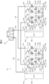
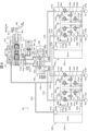
- FIG. 1 is a diagram showing the configuration of a hydraulic control system 101 of Embodiment 1.
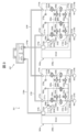
- FIG. FIG. 10 is a diagram showing the configuration of a hydraulic control system 201 of Embodiment 2;
- FIG. 11 is a diagram showing the configuration of a hydraulic control system 301 of Embodiment 3;
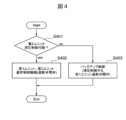
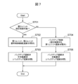
- 4 is a flow chart showing the flow of brake control processing in the control unit in Embodiments 1, 2, and 3.
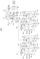
- FIG. 11 is a diagram showing the configuration of a hydraulic control system 401 of Embodiment 4;
- FIG. 11 is a diagram showing the configuration of a hydraulic control system 501 of Embodiment 5;
- 14 is a flow chart showing the flow of brake control processing in a control unit in Embodiments 4 and 5.
- FIG. 1 is a configuration diagram of a hydraulic control system 101 of Embodiment 1.
- the hydraulic pressure control system 101 is a system that is mainly assumed to be applied to an automatic driving vehicle of Level 4 or higher, and constitutes a brake device mounted on the vehicle.
- the suffix p indicates that it corresponds to the primary system (P system) of the wheel cylinder 118 .
- the letter s at the end of the symbol indicates that it corresponds to the secondary system (S system) of the wheel cylinder 118 .
- S system secondary system
- descriptions of p and s are omitted when the P and S systems are not distinguished.
- the suffix "a" indicates that it corresponds to the left front wheel FL.
- the suffix b indicates the right front wheel FR
- the suffix c indicates the left rear wheel RL
- the suffix d indicates the right rear wheel RR.
- the symbols a, b, c, and d are omitted when the wheels FL to RR are not distinguished.
- the suffix f of the reference numeral indicates that it corresponds to the front wheels FL/FR
- the suffix r indicates that it corresponds to the rear wheels RL/RR. If the front wheels and rear wheels are not distinguished, the symbols f and r are omitted.
- Hydraulic pressure control system 101 generates brake hydraulic pressure (wheel cylinder hydraulic pressure) in wheel cylinder (braking force imparting unit) 118, thereby moving the brake pads provided on each wheel FL to RR to the wheel side. brake disc to apply braking force to each wheel FL to RR.
- the hydraulic control system 101 includes a first unit 102p and a second unit 102s.
- the first unit 102p and the second unit 102s are units in which the pressure source 103, the cutoff valve 104, the pressure regulating means 105, and the ECU 106 are integrally provided.
- the first unit 102p and the second unit 102s have unit connection ports 113, suction ports 114, and wheel cylinder ports 115.
- the unit connection port 113 is connected to the unit connection pipe 119 and is connected to the cutoff valve 104 via the connection fluid path 111 . Also, the first unit 102 p and the second unit 102 s are connected via a unit connection pipe 119 .
- the suction port 114 is connected to the suction hose 116 and is connected to the pressure source 103 via the connecting liquid path 112 . Also, the first unit 102 p and the second unit 102 s are connected to the reservoir tank 107 via the suction hose 116 .
- a reservoir tank 107 is a brake fluid source that stores brake fluid, and is a low pressure portion that is released from atmospheric pressure.
- the wheel cylinder port 115 is connected to the wheel cylinder pipe 117 and is connected to the pressure regulating means 105 via the connecting liquid passage 110 .
- the first unit 102 p and the second unit 102 s are connected to a wheel cylinder 118 via a wheel cylinder pipe 117 .
- the primary system of the first unit 102p is connected to the left front wheel wheel cylinder 118a and the right rear wheel wheel cylinder 118d, while the secondary system of the second unit 102s is connected to the right front wheel wheel cylinder 118b and the left rear wheel wheel cylinder 118c.
- X (cross) piping configuration is adopted. It should be noted that an H pipe may be used to connect the front wheels to the primary system and the rear wheels to the secondary system.
- the pressure source 103 and the pressure regulating means 105 are connected via a connecting liquid path 108 .
- the shutoff valve 104 and the pressure regulating means 105 are connected via a connecting liquid path 109 .
- the pressure source 103 Based on a command from the ECU 106, the pressure source 103 sucks the brake fluid stored in the reservoir tank 107 and discharges the required flow rate to the pressure regulating means 105.
- the pressure adjusting means 105 adjusts the pressure of the brake fluid supplied from the pressure source 103 based on a command from the ECU 106 and outputs a desired pressure to the wheel cylinder 118 and the cutoff valve 104 side.
- the connecting liquid passage 109 and the connecting liquid passage 110 are in communication (not shown).
- the shut-off valve 104 opens/closes based on a command from the ECU 106 to communicate/shut off the connecting fluid passage 109 and the connecting fluid passage 111 .
- the shut-off valve 104 has a so-called normally open structure, and is open when there is no command (electrical signal) from the ECU 106 and when no electricity is supplied. state.
- the ECU 106 is an electronic control unit (ECU) that controls the first unit 102p and the second unit 102s. , controls the pressure regulating means 105 .
- ECU electronice control unit
- the wheel cylinders 118a and 118d of this embodiment correspond to the first wheel cylinders in the claims
- the wheel cylinders 118b and 118c of the present embodiment correspond to the second wheel cylinders in the claims.
- the first unit 102p and the second unit 102s correspond to the first hydraulic unit and the second hydraulic unit in the claims
- the unit connection pipe 119 of this embodiment corresponds to the connection pipe in the claims.
- the shut-off valves 104p and 104s of this embodiment correspond to the first shut-off valve and the second shut-off valve in the claims
- the ECUs 106p and 106s of the present embodiment correspond to the first control section and the second control section in the claims.
- the pressure sources 103p and 103s of this embodiment correspond to the first pressure-feeding section and the second pressure-feeding section in the claims, and the pressure regulating means 105p and 105s of the present embodiment correspond to the first pressure regulating section in the claims. It corresponds to the second pressure regulator.
- the cutoff valve 104 is closed by a command from the ECU 106 to cut off the connection liquid passage 109 and the connection liquid passage 111.
- FIG. It also controls the pressure source 103 and pressure regulating means 105 to output a desired pressure to the wheel cylinder 118 and apply the necessary braking force to each of the wheels FL to RR of the wheel cylinder 118 .
- step S402 normal control when the system is normal, described in [0025] above, continues.
- step S403 the process shifts to backup control. That is, the shutoff valve 104p of the first unit 102p is opened. By this operation, the connecting liquid passage 109p and the connecting liquid passage 111p are communicated with each other, and the pressure adjusted by the pressure adjusting means 105p passes through the unit connecting pipe 119 together with the wheel cylinders 118a/118d to the second unit 102s. Join unit connection port 113s.
- the pressure source 103s, the shutoff valve 104s, and the pressure regulating means 105s are deactivated (de-energized), the shutoff valve 104s is opened, and the connecting liquid path 109s is connected.
- the connection liquid paths 111s are communicated with each other.
- the ECUs 106p and 106s open the shutoff valves 104p and 104s, respectively, when detecting a failure in one of the first unit 102p and the second unit 102s.
- the pressure regulated by the pressure regulating means 105p of the first unit 102p is transferred from the unit connection port 113s of the second unit 102s to the connecting fluid path 111s, the connecting fluid path 109s, the pressure regulating means 105s, the connecting fluid path 110b/ Also joins wheel cylinders 118b/118c via 110c, wheel cylinder ports 115b/115c, and wheel cylinder piping 117b/117c.
- the hydraulic control system 101 of Embodiment 1 includes two units having the same configuration, a first unit 102p and a second unit 102s, the first unit 102p having an ECU 106p and the second unit 102s having an ECU 106s. Each unit is provided with a shut-off valve 104 controlled only by the ECU 106 of each unit. connected by
- each of the two units has the same configuration and does not have a configuration for controlling the shutoff valves from two ECUs as shown in the prior art, so there is also the advantage of simplifying the system configuration.
- FIG. 2 is a configuration diagram of a hydraulic pressure control system 201 of Embodiment 2, which, like Embodiment 1, is mainly intended for application to automatic driving vehicles of Level 4 or higher.
- Hydraulic pressure control system 201 generates brake hydraulic pressure (wheel cylinder hydraulic pressure) in wheel cylinders (braking force applying unit) 218, so that the brake pads provided on each wheel FL to RR are adjusted to the wheel side. brake disc to apply braking force to each wheel FL to RR.
- the hydraulic control system 201 includes a first unit 202p and a second unit 202s.
- the first unit 202p and the second unit 202s are units in which the pressure source 203, the cutoff valve 204, the pressure regulating means 205, and the ECU 206 are integrally provided.
- the first unit 202p and the second unit 202s have unit connection ports 213, suction ports 214, and wheel cylinder ports 215.
- the unit connection port 213 is connected to the unit connection pipe 219 and is connected to the cutoff valve 204 via the connection liquid path 211 . Also, the first unit 202 p and the second unit 202 s are connected via a unit connection pipe 219 .
- the suction port 214 is connected to the suction hose 216 and is connected to the pressure source 203 via the connecting liquid passage 212 .
- the first unit 202 p and the second unit 202 s are connected to the reservoir tank 207 via the suction hose 216 .
- the reservoir tank 207 is divided into two compartments, the primary liquid chamber 257p is connected to the first unit 202p, and the secondary liquid chamber 257s is connected to the second unit 202s.
- the reservoir tank 207 is a brake fluid source that stores brake fluid, and is a low-pressure portion that is released from the atmospheric pressure.
- the wheel cylinder port 215 is connected to the wheel cylinder pipe 217 and is connected to the pressure regulating means 205 via the connecting liquid passage 210 .
- the first unit 202 p and the second unit 202 s are connected to the wheel cylinder 218 via the wheel cylinder pipe 217 .
- the primary system of the first unit 202p connects with the left front wheel wheel cylinder 218a and the right rear wheel wheel cylinder 218d, while the secondary system of the second unit 202s connects with the right front wheel wheel cylinder 218b and the left rear wheel wheel cylinder 218c.
- X (cross) piping configuration is adopted. It should be noted that an H pipe may be used to connect the front wheels to the primary system and the rear wheels to the secondary system.
- the pressure source 203 and the pressure regulating means 205 are connected via a connecting liquid path 208 . Also, the shutoff valve 204 and the pressure regulating means 205 are connected via a connecting liquid passage 209 .
- the pressure source 203 is composed of a pump 223 and a motor 233 that drives the pump. Based on a command from the ECU 206 , the rotation of the motor 233 is controlled to suck the brake fluid stored in the reservoir tank 207 and discharge the required flow rate to the pressure regulating means 205 .
- the pressure regulating means 205 comprises a pressure increase control valve 225, a pressure reduction control valve 235, a communication valve 245, a pressure sensor 255, and a pressure sensor 265, and adjusts the brake fluid supplied from the pressure source 203 based on a command from the ECU 206.
- pressure That is, the pressure detected by the pressure sensors 255/265 is fed back, and when increasing the pressure, the pressure increase control valve 225 is opened and the pressure decrease control valve 235 is closed. Open valve 235 to obtain the desired pressure.
- the regulated pressure is output to the wheel cylinder 218 and to the cutoff valve 204 side by opening the communication valve 245 .
- the shut-off valve 204 opens/closes based on a command from the ECU 206 to communicate/shut off the connecting fluid passage 209 and the connecting fluid passage 211 .
- the shut-off valve 204 has a so-called normally open structure, and is open when there is no command (electrical signal) from the ECU 206 and when no electricity is supplied. state.
- the ECU 206 is an electronic control unit (ECU) that controls the first unit 202p and the second unit 202s. , controls the pressure regulating means 205 .
- ECU electronice control unit
- the cutoff valve 204 is closed by a command from the ECU 206 to cut off the connection fluid path 209 and the connection fluid path 211.
- FIG. It also controls the pressure source 203 and pressure regulating means 205 to output a desired pressure to the wheel cylinder 218 and apply the necessary braking force to each wheel FL to RR of the wheel cylinder 218 .
- step S402 the normal control when the system is normal, described in [0050] above, continues.
- step S403 the process shifts to backup control. That is, the shutoff valves 204a/204d of the first unit 202p are opened.
- the connecting liquid passage 209a and the connecting liquid passage 211a and the connecting liquid passage 209d and the connecting liquid passage 211d are communicated, and the pressure adjusted by the pressure adjusting means 205a/205d is adjusted together with the wheel cylinders 218a/218d. It joins the unit connection ports 213b/213c of the second unit 202s via the unit connection pipe 219.
- the pressure source 203s, the shutoff valves 204b/204c, and the pressure regulating means 205b/205c are deactivated (de-energized), and the shutoff valves 204b/204c are opened.
- the connection liquid path 209b and the connection liquid path 211b and the connection liquid path 209c and the connection liquid path 211c are in communication.
- the pressure regulated by the pressure regulating means 205a/205d of the first unit 202p is supplied from the unit connection ports 213b/213c of the second unit 202s to the connecting liquid paths 211b/211c, the connecting liquid paths 209b/209c, the connecting liquid It also joins wheel cylinders 218b/218c via passages 210b/210c, wheel cylinder ports 215b/215c, and wheel cylinder lines 217b/217c.
- the hydraulic control system 201 of Embodiment 2 includes two units having the same configuration, a first unit 202p and a second unit 202s, the first unit 202p having an ECU 206p and the second unit 202s having an ECU 206s. Each unit is provided with a shutoff valve 204 controlled only by the ECU 206 of each unit. connected by
- each of the two units has the same configuration and does not have a configuration for controlling the shutoff valves from two ECUs as shown in the prior art, so there is also the advantage of simplifying the system configuration.
- FIG. 3 is a configuration diagram of a hydraulic pressure control system 301 of Embodiment 3, which, like Embodiment 1, is mainly assumed to be applied to an automatic driving vehicle of Level 4 or higher. Since the basic configuration of the third embodiment is the same as that of the second embodiment, only the parts different from the second embodiment will be described.
- the hydraulic control system 301 includes a first unit 302p and a second unit 302s.
- the first unit 302p and the second unit 302s are units in which the pressure source 203, the shutoff valve 204, the pressure regulating means 305, and the ECU 206 are integrally provided.
- Embodiment 3 is the same as Embodiment 2 except for the pressure regulating means 305, the portion related to the pressure regulating means 305 will be described below.
- the pressure regulating means 305 is composed of a pressure increase control valve 325, a pressure reduction control valve 335, a communication valve 345, a pressure regulating valve 385, and a pressure sensor 265, and adjusts the brake fluid supplied from the pressure source 203 based on a command from the ECU 206. pressure. That is, the pressure detected by the pressure sensor 265 is fed back, and the first desired pressure is obtained by the pressure regulating valve 385 and sent to the cutoff valve 204 side and the pressure increase control valve 325 side via the communication valve 345 . Further, a second desired pressure is obtained by the pressure increase control valve 325 and the pressure decrease control valve 335 and output to the wheel cylinder 218 .
- the pressure increase control valve 325 and the pressure decrease control valve 335 in the pressure regulating means 305 operate only during vehicle behavior control such as ABS and ESC. does not work.
- the pressure reducing control valve 335 has a so-called normally closed structure, and is closed when there is no command (electrical signal) from the ECU 206 and is not energized. It becomes a cutoff state.
- the first desired pressure is output to the wheel cylinder 218 as it is.
- the ECU 206 is an electronic control unit (ECU) that controls the first unit 302p and the second unit 302s. , controls the pressure regulating means 305 .
- ECU electronice control unit
- the cutoff valve 204 is closed by a command from the ECU 206 to cut off the connection fluid path 209 and the connection fluid path 211.
- FIG. Also, it controls the pressure source 203 and the pressure regulating means 305 to output a desired pressure to the wheel cylinder 218 and apply the necessary braking force to each of the wheels FL to RR of the wheel cylinder 218 .
- step S402 the normal control when the system is normal, described in [0069] above, continues.
- step S403 the process shifts to backup control. That is, the shutoff valves 204a/204d of the first unit 302p are opened.
- the connection liquid path 209a and the connection liquid path 211a and the connection liquid path 209d and the connection liquid path 211d are communicated, and the pressure (first desired pressure) adjusted by the pressure adjustment means 305p is Together with the wheel cylinders 218a/218d, they join unit connection ports 213b/213c of the second unit 302s via unit connection piping 219.
- the pressure source 203s, the cutoff valves 204b/204c, and the pressure regulating means 305s are deactivated (de-energized), the cutoff valves 204b/204c are opened, and the connection is established.
- the connection liquid paths 209b and 210b and the connection liquid paths 209c and 210c communicate with each other.
- the pressure regulated by the pressure regulating means 305p of the first unit 302p flows from the unit connection ports 213b/213c of the second unit 302s to the connecting liquid paths 211b/211c, the connecting liquid paths 209b/209c, and the connecting liquid path 210b. /210c, wheel cylinder ports 215b/215c, and wheel cylinder piping 217b/217c to wheel cylinders 218b/218c.
- the hydraulic control system 301 of Embodiment 3 includes two units having the same configuration, a first unit 302p and a second unit 302s, the first unit 302p having an ECU 206p and the second unit 302s having an ECU 206s. Each unit is provided with a shutoff valve 204 controlled only by the ECU 206 of each unit. connected by
- each of the two units has the same configuration and does not have a configuration for controlling the shutoff valves from two ECUs as shown in the prior art, so there is also the advantage of simplifying the system configuration.
- FIG. 5 is a configuration diagram of the hydraulic control system 401 of the fourth embodiment.
- the hydraulic pressure control system 401 is a system that is assumed to be applied to an automatic driving vehicle of Level 3 or higher, and is configured in consideration of the application of braking force by the driver's brake pedal operation. .
- Hydraulic pressure control system 401 generates brake hydraulic pressure (wheel cylinder hydraulic pressure) in wheel cylinders (braking force applying unit) 418, so that the brake pads provided on each wheel FL to RR are adjusted to the wheel side. brake disc to apply braking force to each wheel FL to RR.
- the hydraulic control system 401 includes a first unit 402p and a second unit 402s.
- the first unit 402p and the second unit 402s are units in which the pressure source 403, the cutoff valve 404, the pressure regulating means 405, and the ECU 406 are integrally provided.
- a brake pedal 460 is connected to the master cylinder 470 .
- the first unit 402p and the second unit 402s have unit connection ports 413, suction ports 414, and wheel cylinder ports 415.
- the unit connection port 413 is connected to the unit connection pipe 419 and is connected to the cutoff valve 404 via the connection liquid path 411 . Also, the first unit 402p and the second unit 402s are connected via unit connection pipes 419p/419s and connection liquid paths 495p/495s in the fail-safe unit 480 .
- the suction port 414 is connected to the suction hose 416 and is connected to the pressure source 403 via the connecting liquid passage 412 . Also, the first unit 402 p and the second unit 402 s are connected to the reservoir tank 407 via the suction hose 416 .
- a reservoir tank 407 is a brake fluid source that stores brake fluid, and is a low-pressure portion that is released from atmospheric pressure.
- the wheel cylinder port 415 is connected to the wheel cylinder pipe 417 and is connected to the pressure regulating means 405 via the connecting liquid passage 410 .
- the first unit 402 p and the second unit 402 s are connected to a wheel cylinder 418 via a wheel cylinder pipe 417 .
- the primary system of the first unit 402p connects with the left front wheel wheel cylinder 418a and the right rear wheel wheel cylinder 418d, while the secondary system of the second unit 402s connects with the right front wheel wheel cylinder 418b and the left rear wheel wheel cylinder 418c.
- X (cross) piping configuration is adopted. It should be noted that an H pipe may be used to connect the front wheels to the primary system and the rear wheels to the secondary system.
- the pressure source 403 and the pressure regulating means 405 are connected via a connecting liquid path 408 .
- the shutoff valve 404 and the pressure regulating means 405 are connected via a connecting liquid passage 409 .
- the brake pedal 460 receives the driver's depression force and transmits the force to the master cylinder 470 .
- the master cylinder 470 has a master cylinder body 471 , a reservoir tank 477 and an output port 479 .
- the master cylinder body 471 converts force transmitted from the brake pedal 460 into pressure.
- the reservoir tank 477 is a brake fluid source that stores the brake fluid to be supplied to the master cylinder body 471, and is a low pressure portion that is released from atmospheric pressure.
- the output port 479 connects with the master cylinder piping 491 .
- the fail-safe unit 480 has a backup cutoff valve 484, an ECU 486, a master cylinder port 493, and a unit connection port 496.
- the master cylinder port 493 is connected to the master cylinder pipe 491 and is connected to the backup cutoff valve 484 via the connecting liquid passage 494 .
- Master cylinder 470 and fail safe unit 480 are connected via master cylinder piping 491 .
- the unit connection port 496 is connected to the unit connection pipe 419 and is connected to the backup cutoff valve 484 via the connection liquid passage 495 . It should be noted that the unit connection ports 496p/496s are connected to the connection liquid paths 495p/495s in the fail-safe unit 480 as shown in FIG.
- the pressure source 403 Based on a command from the ECU 406 , the pressure source 403 sucks the brake fluid stored in the reservoir tank 407 and discharges the required flow rate to the pressure regulating means 405 .
- the pressure adjusting means 405 adjusts the pressure of the brake fluid supplied from the pressure source 403 and outputs a desired pressure to the wheel cylinder 418 and the cutoff valve 404 side.
- the connecting liquid path 409 and the connecting liquid path 410 are in communication (not shown).
- the shut-off valve 404 opens/closes based on a command from the ECU 406 to communicate/shut off the connecting fluid passage 409 and the connecting fluid passage 411 .
- the shut-off valve 404 has a so-called normally open structure, and is open when there is no command (electrical signal) from the ECU 406 and when no electricity is supplied. state.
- the ECU 406 is an electronic control unit (ECU) that controls the first unit 402p and the second unit 402s. , controls the pressure regulating means 405 .
- ECU electronice control unit
- the amount of operation of the brake pedal 460 by the driver for example, the amount of operation is detected by a pedal stroke sensor (not shown) or the like, and the target brake fluid pressure can be set based on the detected amount. good.
- a backup cutoff valve 484 in the fail-safe unit 480 opens/closes based on a command from the ECU 486 to connect/block the connecting fluid passage 494 and the connecting fluid passage 495 .
- the backup cutoff valve 484 has a so-called normally open structure, and is open when there is no command (electrical signal) from the ECU 486 and is de-energized. A communication state is established.
- the ECU 486 is an electronic control unit (ECU) that receives signals from other ECUs and controls the backup cutoff valve 484 .
- the ECU 486 of this embodiment corresponds to the third control section in the claims, and the backup cutoff valve 484 of this embodiment corresponds to the third cutoff valve in the claims.
- the cutoff valve 404 is closed by a command from the ECU 406 to cut off the connection fluid path 409 and the connection fluid path 411.
- FIG. It also controls the pressure source 403 and the pressure adjusting means 405 to output a desired pressure to the wheel cylinder 418 .
- the backup cutoff valve 484 is opened by a command from the ECU 486.
- shutoff valves 404 are closed in the first unit 402p and the second unit 402s. It is possible to output a desired pressure to the wheel cylinder 418 without flowing out to the cylinder 470 (reservoir tank 477) side, and to apply the necessary braking force to each wheel FL to RR of the wheel cylinder 418.
- step S702 the first unit 402p and the second unit 402s continue normal control when the system is normal, described in [0100] above, and proceed to step S703.
- step S703 the backup cutoff valve 484 is opened in the fail-safe unit 480 as described in [0100] above.
- desired pressure can be output to wheel cylinder 418, and necessary braking force can be applied to wheels FL-RR of wheel cylinder 418.
- step S704 the process shifts to backup control. That is, the cutoff valve 404p of the first unit 402p is opened. By this operation, the connecting fluid passage 409p and the connecting fluid passage 411p are communicated, and the pressure adjusted by the pressure adjusting means 405p passes through the unit connecting pipe 419p together with the wheel cylinders 418a/418d, and the fail safe unit 480. Join unit connection port 496p.
- step S705 the backup cutoff valve 484 is closed in the fail-safe unit 480. This prevents the pressure regulated by the pressure regulating means 405p from flowing out to the master cylinder 470 (reservoir tank 477) side, and the pressure is transferred from the unit connection port 496p of the fail-safe unit 480 to the connection fluid path 495p. /495s, the unit connection port 496s, the unit connection pipe 419s, and joins the unit connection port 413s of the second unit 402s.
- the pressure source 403s, the cutoff valve 404s, and the pressure regulating means 405s are deactivated (de-energized), the cutoff valve 404s is opened, and the connecting liquid path 409s is connected.
- the connection liquid paths 411s are communicated with each other.
- the pressure adjusted by the pressure adjusting means 405p of the first unit 402p is transferred from the unit connection port 413s of the second unit 402s to the connecting liquid path 411s, the connecting liquid path 409s, the pressure adjusting means 405s, the connecting liquid path 410b/ Also joins wheel cylinders 418b/418c via 410c, wheel cylinder ports 415b/415c, and wheel cylinder piping 417b/417c.
- the driver's stepping force applied to the brake pedal 460 is transmitted to the master cylinder main body 471 and converted into pressure.
- the pressure is applied from output port 479 to master cylinder port 493 of failsafe unit 480 via master cylinder piping 491 .
- the pressure generated in the master cylinder 470 by the driver's stepping force is transferred from the unit connection port 413 to the connecting fluid passage 411, the connecting fluid passage 409, the pressure adjusting means 405, the connecting fluid passage 410, the wheel cylinder port 415, and the wheel cylinder piping 417. to the wheel cylinder 418 via the wheel cylinder 418 to apply the necessary braking force to each of the wheels FL to RR of the wheel cylinder 418 .
- the hydraulic control system 401 of the fourth embodiment includes a brake pedal 460, a master cylinder 470, a fail-safe unit 480, and two units having the same configuration, a first unit 402p and a second unit 402s.
- 402p has an ECU 406p
- the second unit 402s has an ECU 106s
- each unit is provided with a shutoff valve 404 controlled only by the ECU 406 of each unit.
- a backup cutoff valve 484 controlled by an ECU 486 is provided between the unit connection pipe 419 and the master cylinder 470 .
- the two units, the first unit 402p and the second unit 402s have the same configuration, and do not have a configuration for controlling shutoff valves from two ECUs as shown in the prior art, thus simplifying the system configuration.
- the two units, the first unit 402p and the second unit 402s have the same configuration, and do not have a configuration for controlling shutoff valves from two ECUs as shown in the prior art, thus simplifying the system configuration.
- the pressure generated in the master cylinder 470 due to the driver's pedaling force is reduced. It is added to the wheel cylinder 418, and it becomes possible to apply the necessary braking force to each wheel FL to RR of the wheel cylinder 418, thereby ensuring even higher reliability.
- FIG. 6 is a configuration diagram of the hydraulic control system 501 of the fifth embodiment.
- the hydraulic control system 501 is a system that is assumed to be applied to an automatic driving vehicle of Level 3 or higher, and is configured in consideration of the application of braking force by the driver's operation of the brake pedal. .
- Hydraulic pressure control system 501 generates brake hydraulic pressure (wheel cylinder hydraulic pressure) in wheel cylinders (braking force applying unit) 518, so that the brake pads provided on each wheel FL to RR are adjusted to the wheel side. brake disc to apply braking force to each wheel FL to RR.
- the hydraulic control system 501 includes a first unit 502p and a second unit 502s.
- the first unit 502p and the second unit 502s are units in which the pressure source 503, the cutoff valve 504, the pressure regulating means 505, and the ECU 506 are integrally provided.
- the first unit 502p and the second unit 502s have unit connection ports 513, suction ports 514, and wheel cylinder ports 515.
- the unit connection port 513 is connected to the unit connection pipe 519 and is connected to the cutoff valve 504 via the connection liquid path 511 .
- the first unit 502p and the second unit 502s are connected via unit connection pipes 519a/519b, unit connection pipes 519c/519d, connection liquid paths 595a/595b, and connection liquid paths 595c/595d in the fail safe unit 580. be done.
- the suction port 514 is connected to the suction hose 516 and is connected to the pressure source 503 via the connecting liquid path 512 . Also, the first unit 502 p and the second unit 502 s are connected to the liquid chamber 567 of the reservoir tank 577 via the suction hose 516 .
- a reservoir tank 577 is a brake fluid source that stores brake fluid, and is a low-pressure portion that is released from atmospheric pressure.
- the reservoir tank 577 is divided into three liquid chambers 557p/557s/567, and the liquid chambers 557p/557s are connected to a master cylinder 570 which will be described later.
- the wheel cylinder port 515 is connected to the wheel cylinder pipe 517 and is connected to the pressure regulating means 505 via the connecting liquid passage 510 .
- the first unit 502 p and the second unit 502 s are connected to a wheel cylinder 518 via a wheel cylinder pipe 517 .
- the primary system of the first unit 502p connects with the left front wheel wheel cylinder 518a and the right rear wheel cylinder 518d, while the secondary system of the second unit 502s connects with the right front wheel wheel cylinder 518b and the left rear wheel cylinder 518c.
- X (cross) piping configuration is adopted. It should be noted that an H pipe may be used to connect the front wheels to the primary system and the rear wheels to the secondary system.
- the pressure source 503 and the pressure regulating means 505 are connected via a connecting liquid path 508 .
- the shutoff valve 504 and the pressure regulating means 505 are connected via a connecting liquid passage 509 .
- the brake pedal 560 receives the driver's pedaling force and transmits the force to the master cylinder 570 via the push rod 562 .
- the master cylinder 570 has a master cylinder body 571, a reservoir tank 577, and an output port 579.
- the master cylinder main body 571 has a piston 572 inside, converts force transmitted from the brake pedal 560 into pressure, and outputs the pressure from the pressure chamber 573 to the output port 579 via the connecting fluid passage 574 .
- the reservoir tank 577 is a brake fluid source that stores brake fluid to be supplied to the master cylinder main body 571, and is a low-pressure portion that is released from atmospheric pressure. /573s, respectively, with brake fluid.
- the output port 579 connects with the master cylinder piping 591 .
- the master cylinder 570 is integrally provided with a stroke simulator 563 .
- the stroke simulator 563 operates according to the driver's braking operation to generate a brake pedal feeling.
- the primary piston 572p of the master cylinder 570 moves, and the brake fluid pushed out thereby flows into the stroke simulator 563 through the connecting fluid passage 578 and the input port 568, displacing the simulator piston 564.
- a pedal stroke is generated.
- a spring 566 is provided in contact with the end face of the simulator piston 564 on the side to which the brake fluid from the master cylinder 570 is not applied. The pressure generated by the reaction force is transmitted to the primary piston 572p of the master cylinder 570 to generate the pedal reaction force.
- connection fluid path 578 is provided with a stroke simulator cut valve 576 controlled by an ECU 586 in the fail safe unit 580 .
- the fail-safe unit 580 has a backup cutoff valve 584, an ECU 586, a master cylinder port 593, and a unit connection port 596.
- the master cylinder port 593 is connected to the master cylinder pipe 591 and is connected to the backup cutoff valve 584 via the connecting liquid passage 594 .
- Master cylinder 570 and fail safe unit 580 are connected via master cylinder piping 591 .
- the unit connection port 596 is connected to the unit connection pipe 519 and is connected to the backup cutoff valve 584 via the connection liquid passage 595 .
- the unit connection ports 596a/596b are connected via connection liquid paths 595a/595b within the fail-safe unit 580, and the unit connection ports 596c/596d are connected within the fail-safe unit 580 via connection liquid paths. 595c/595d.
- the pressure source 503 is composed of a pump 523 and a motor 533 that drives the pump. Based on a command from the ECU 506 , the rotation of the motor 533 is controlled to suck the brake fluid stored in the reservoir tank 577 and discharge the required flow rate to the pressure regulating means 505 .
- the pressure regulating means 505 comprises a pressure increase control valve 525, a pressure reduction control valve 535, a communication valve 545, a pressure sensor 555, and a pressure sensor 565, and adjusts the brake fluid supplied from the pressure source 503 based on a command from the ECU 506. pressure. That is, the pressure detected by the pressure sensors 555/565 is fed back, and when increasing the pressure, the pressure increase control valve 525 is opened and the pressure decrease control valve 535 is closed. Open valve 535 to obtain the desired pressure. The regulated pressure is output to the wheel cylinder 518 and cutoff valve 504 side by opening the communication valve 545 .
- the shut-off valve 504 opens/closes based on a command from the ECU 506 to communicate/shut off the connecting fluid passage 509 and the connecting fluid passage 511 .
- the shut-off valve 504 has a so-called normally open structure, and is open when there is no command (electrical signal) from the ECU 506 and when there is no electricity, that is, the connecting fluid path 509 and the connecting fluid path 511 are open (the valve is in communication). state.
- the ECU 506 is an electronic control unit (ECU) that controls the first unit 502p and the second unit 502s. , controls the pressure regulating means 505 .
- the operation amount of the brake pedal 560 by the driver for example, the operation amount may be detected by a pedal stroke sensor 561 or the like, and the target brake fluid pressure may be set based on the detected operation amount.
- a stroke simulator cut valve 576 provided in the master cylinder 570 opens/closes based on a command from the ECU 586 in the fail-safe unit 580, and communicates/shuts off the connecting fluid passage 578. It communicates/disconnects with the simulator 563 .
- a backup cutoff valve 584 in the fail-safe unit 580 opens/closes based on a command from the ECU 586 to connect/block the connecting fluid passage 594 and the connecting fluid passage 595 .
- the backup cutoff valve 584 has a so-called normally open structure, and is open when there is no command (electrical signal) from the ECU 586 and is not energized. A communication state is established.
- the ECU 586 is an electronic control unit (ECU), receives signals from other ECUs, and controls the backup cutoff valve 584 and the stroke simulator cut valve 576 described above.
- ECU electronice control unit
- the cutoff valve 504 is closed by a command from the ECU 506 to cut off the connection fluid path 509 and the connection fluid path 511 . It also controls the pressure source 503 and the pressure adjusting means 505 to output a desired pressure to the wheel cylinder 518 .
- the stroke simulator cut valve 576 is opened according to a command from the ECU 586.
- the backup cutoff valve 584 is opened according to a command from the ECU 586.
- shutoff valves 504 are closed. It is possible to output a desired pressure to the wheel cylinder 518 without flowing out to the cylinder 570 (reservoir tank 577) side, and to apply the necessary braking force to each wheel FL to RR of the wheel cylinder 518.
- a brake pedal feeling is generated in response to the driver's braking operation.
- step S702 the first unit 502p and the second unit 502s continue normal control when the system is normal, described in [0143] above, and proceed to step S703.
- step S703 the backup cutoff valve 584 is opened in the fail-safe unit 580 as described in [0143] above.
- desired pressure can be output to wheel cylinder 518, and necessary braking force can be applied to wheels FL-RR of wheel cylinder 518.
- step S704 the process shifts to backup control. That is, the shutoff valves 504a/504d of the first unit 502p are opened.
- the connecting liquid passage 509a and the connecting liquid passage 511a and the connecting liquid passage 509d and the connecting liquid passage 511d are communicated, and the pressure adjusted by the pressure adjusting means 505a/505d is adjusted together with the wheel cylinders 518a/518d. It joins the unit connection ports 596a/596d of the failsafe unit 580 via the unit connection pipes 519a/519d.
- the stroke simulator cut valve 576 is opened.
- step S705 the backup cutoff valves 584p/584s are closed in the fail-safe unit 580. This prevents the pressure adjusted by the pressure adjusting means 505a/505d from flowing out to the master cylinder 570 (reservoir tank 577) side. It joins the unit connection ports 513b/513c of the second unit 502s via connection fluid paths 595a/595b, connection fluid paths 595c/595d, unit connection ports 596b/596c, and unit connection piping 519b/519c.
- the pressure source 503s, the shutoff valves 504b/504c, and the pressure regulating means 505b/505c are deactivated (de-energized), and the shutoff valves 504b/504c are opened.
- the connection liquid path 509b and the connection liquid path 511b and the connection liquid path 509c and the connection liquid path 511c are in communication.
- the pressure regulated by the pressure regulating means 505a/505d of the first unit 502p is supplied from the unit connection ports 513b/513c of the second unit 502s to the connecting liquid paths 511b/511c, the connecting liquid paths 509b/509c, the connecting liquid It also joins wheel cylinders 518b/518c via passages 510b/510c, wheel cylinder ports 515b/515c, and wheel cylinder lines 517b/517c.
- the desired pressure is output to the wheel cylinder 518 in the same manner as when the system is normal, and the wheel cylinder 518 applies the necessary braking force to each of the wheels FL to RR. It becomes possible to Further, by establishing communication between the master cylinder 570 and the stroke simulator 563, a brake pedal feeling corresponding to the driver's braking operation is generated, as in the normal system state.
- the driver's stepping force applied to the brake pedal 560 is transmitted to the master cylinder main body 571 via the push rod 562 and converted into pressure.
- the pressure is applied from output port 579 to master cylinder port 593 of failsafe unit 480 via master cylinder piping 591 .
- the stroke simulator cut valve 576 has a so-called normally closed structure, and is closed when there is no command (electrical signal) from the ECU 586 and is de-energized. state. Therefore, the brake fluid pushed out from the primary piston 572p of the master cylinder 570 by the driver's brake pedal operation is prevented from flowing into the stroke simulator 563, that is, from reducing the amount of brake fluid supplied to the wheel cylinder 518, which will be described later. can.
- the pressure generated by the master cylinder 570 due to the driver's pedaling force flows from the unit connection port 513 to the wheel cylinder via the connecting fluid passage 511, the connecting fluid passage 509, the connecting fluid passage 510, the wheel cylinder port 515, and the wheel cylinder piping 517. 518, it becomes possible to apply the necessary braking force to each of the wheels FL to RR of the wheel cylinder 518.
- the hydraulic control system 501 of Embodiment 5 includes a brake pedal 560, a master cylinder 570, a fail-safe unit 580, a stroke simulator 563, and two units having the same configuration, a first unit 502p and a second unit 502s.
- the first unit 502p has an ECU 506p
- the second unit 502s has an ECU 506s
- each unit is provided with a shutoff valve 504 controlled only by the ECU 506 of each unit.
- the upstream side of the cutoff valve 504 (the side opposite to the wheel cylinder) is connected by a unit connection pipe 519 , and a backup cutoff valve 584 controlled by the ECU 486 is provided between the unit connection pipe 519 and the master cylinder 570 .
- the stroke simulator 563 can generate a brake pedal feeling (feeling of stepping response) in response to the driver's brake operation, in the same way as when the system is normal, even in the event of a failure.
- the two units, the first unit 502p and the second unit 502s have the same configuration, and do not have a configuration for controlling shutoff valves from two ECUs as shown in the prior art, thus simplifying the system configuration.
- the two units, the first unit 502p and the second unit 502s have the same configuration, and do not have a configuration for controlling shutoff valves from two ECUs as shown in the prior art, thus simplifying the system configuration.
- the pressure source is composed of a pump and a motor that drives the pump. It's okay.
Landscapes
- Engineering & Computer Science (AREA)
- Transportation (AREA)
- Mechanical Engineering (AREA)
- Physics & Mathematics (AREA)
- Fluid Mechanics (AREA)
- Electromagnetism (AREA)
- Regulating Braking Force (AREA)
- Valves And Accessory Devices For Braking Systems (AREA)
- Braking Systems And Boosters (AREA)
Abstract
本発明の課題は、ブレーキ制御装置の故障時においても、確実に全車輪FR~RRにホイルシリンダ液圧を発生し、車両を確実に減速・停止可能、かつシステム構成も簡素化された、自動運転向けに高い信頼性を有するブレーキ制御装置を提供することである。本発明のブレーキ装置101は、第1ホイルシリンダ118a、118dにブレーキ液を供給する第1液圧ユニット102pと、第2ホイルシリンダ118b、118cにブレーキ液を供給する第2液圧ユニット102sと、第1液圧ユニットと第2液圧ユニットとを連結してブレーキ液を流通させる接続配管119とを有する。第1液圧ユニットと第2液圧ユニットは、少なくとも一方の故障を検知した場合に、第1遮断弁104pと第2遮断弁104sをそれぞれ開放させることを特徴とする。
Description
本発明は、自動運転に対応したブレーキ制御装置に関する。
自動運転に関し、SAE J3016に規定される自動運転レベルと責任分担区分によると、所謂Level3以上でシステム側に制御責任が発生し、Level3では、失陥時の最終操作責任はドライバであるが、故障判断と制御遷移はシステム側が保証する。また、Level4以上では全状態をシステムが保証となる。従って、自動運転向けのシステム構成要素においては、高い信頼性が必要であり、失陥時に機能を維持可能とする冗長性を備える必要がある。
ブレーキ制御装置においても、失陥時に車両を確実に減速・停止可能とするための冗長性が不可欠となり、特許文献1には、該冗長性構成として2つの液圧制御ユニット(第1液圧制御ユニット、第2液圧制御ユニット)を備えたブレーキ制御装置が開示されている。
ここで、第1液圧制御ユニットは第1コントロールユニット(ECU)を有し、第2液圧制御ユニットは第2コントロールユニット(ECU)を有する構成であり、両ユニットに接続するマスタシリンダとホイルシリンダ間の連通を遮断する遮断弁は、該2つのコントロールユニット各々から制御が可能である。従って、例えば、第1コントロールユニットが、第2液圧制御ユニットに故障が生じていると判断した場合、第1コントロールユニットより該遮断弁を閉方向に制御することで、マスタシリンダとホイルシリンダとの連通の遮断が可能となる。正常時と同様に第1液圧制御ユニットのアクチュエータを制御することにより前輪FR,FLの目標ホイルシリンダ液圧を実現できるとともに、第1液圧制御ユニットのポンプの吐出液圧は、前輪FR,FLのホイルシリンダに供給されるだけでなく、該ポンプと後輪RL,RRのホイルシリンダとを接続する液路(吐出液路13A、接続液路11A(11PA,11SA)、中継液路11I(11IS,11IP)、接続液路11B(11PB,11SB)等)を介して、後輪RL,RRのホイルシリンダ102にも供給することが可能となり、従って、全車輪FR~RRについてホイルシリンダ液圧発生が可能となり、適切な液圧(=制動力)を確保可能である。
上記従来のブレーキ制御装置では、遮断弁は第1液圧制御ユニット(第1コントロールユニット)側に設置されているため、例えば、第1コントロールユニットの故障により該遮断弁自体が動作不能となった場合は、第2液圧制御ユニット(第2コントロールユニット)側が正常であっても、該遮断弁を閉方向に制御することはできず、第2液圧制御ユニットにおけるポンプの吐出液圧はマスタシリンダ・リザーバタンクへ抜けてしまい、従って、第2液圧制御ユニットに直接接続される後輪RL,RRのホイルシリンダとともに、第1液圧制御ユニットに接続される前輪FR,FLのホイルシリンダに対しても、該ポンプ吐出液圧を供給することができず、そのため、適切な液圧の確保が困難となる。
また、どちらか一方の液圧制御ユニット(コントロールユニット)に設置される弁を、他のコントロールユニットから制御するためには、コントロールユニット構成や、両コントロールユニットを繋ぐハーネスが新たに必要となり、システム構成の複雑化を招くという課題も生じる。
本発明の目的は、このような故障時においても、確実に全車輪FR~RRについてホイルシリンダ液圧を発生し、車両を確実に減速・停止可能、かつシステム構成も簡素化された、自動運転向けに高い信頼性を有するブレーキ制御装置を提供することにある。
上記課題を解決するために、本発明のブレーキ制御装置は、車両に搭載されるブレーキ装置であって、少なくとも一つの第1ホイルシリンダにブレーキ液を供給する第1液圧ユニットと、少なくとも一つの第2ホイルシリンダにブレーキ液を供給する第2液圧ユニットと、前記第1液圧ユニットと前記第2液圧ユニットとを連結して前記ブレーキ液を流通させる接続配管と、を有し、前記第1液圧ユニットは、前記接続配管との間における前記ブレーキ液の流通を遮断する第1遮断弁と、該第1遮断弁の開閉を制御する第1制御部と、を有し、前記第2液圧ユニットは、前記接続配管との間における前記ブレーキ液の流通を遮断する第2遮断弁と、該第2遮断弁の開閉を制御する第2制御部と、を有し、前記第1制御部と前記第2制御部は、前記第1液圧ユニットと前記第2液圧ユニットの少なくとも一方の故障を検知した場合に、前記第1遮断弁と前記第2遮断弁をそれぞれ開放させる。
本発明によれば、2つの液圧ユニット及び各ユニットが有する制御部は分離されているため、どちらか一方の液圧ユニットに故障が生じても、他方の液圧ユニットに該故障の影響は無く、従って、他方の液圧ユニットからの吐出液圧を第1ホイルシリンダ及び第2ホイルシリンダに供給でき、制動力の確保が可能となるため、より高い信頼性を得ることができる。
〔実施形態1〕
図1は実施形態1の液圧制御システム101の構成図である。
液圧制御システム101は主にLevel4以上の自動運転車両への適用を想定したシステムであり、車両に搭載されるブレーキ装置を構成する。図1の各部において、符合の末尾pはホイルシリンダ118のプライマリ系統(P系統)に対応することを示す。符合の末尾sはホイルシリンダ118のセカンダリ系統(S系統)に対応することを示す。以下、P,S系統を区別しない場合にはp,sの記載を省略する。また、符合の末尾aは、左前輪FLに対応することを示す。同様に末尾bは右前輪FR、末尾cは左後輪RL、末尾dは右後輪RRに対応することを示す。各車輪FL~RRを区別しない場合はa,b,c,dの符合を省略する。また、符号の末尾fは、前輪FL/FRに対応することを示し、末尾rは後輪RL/RRに対応することを示す。前輪、後輪を区別しない場合は、f,rの符号を省略する。
液圧制御システム101は、ホイルシリンダ(制動力付与部)118にブレーキ液圧(ホイルシリンダ液圧)を発生させることにより、各車輪FL~RRに設けられたブレーキパッドを、車輪側に設けられたブレーキディスクに押し付け、各車輪FL~RRに制動力を付与する。
液圧制御システム101は、第1ユニット102pおよび第2ユニット102sを備える。第1ユニット102p、第2ユニット102sは、各々、圧力源103、遮断弁104、調圧手段105、ECU106が一体に設けられたユニットである。
第1ユニット102pおよび第2ユニット102sは、ユニット接続ポート113、サクションポート114、ホイルシリンダポート115を有する。ユニット接続ポート113は、ユニット接続配管119に接続し、接続液路111を介し、遮断弁104と接続する。また、第1ユニット102pおよび第2ユニット102sは、ユニット接続配管119を介して接続される。
サクションポート114は、サクションホース116と接続し、接続液路112を介し、圧力源103と接続する。また、第1ユニット102pおよび第2ユニット102sは、サクションホース116を介しリザーバタンク107と接続する。リザーバタンク107はブレーキ液を貯留するブレーキ液源であり、大気圧解放された低圧部である。
ホイルシリンダポート115は、ホイルシリンダ配管117と接続し、接続液路110を介し調圧手段105と接続する。また、第1ユニット102pおよび第2ユニット102sは、ホイルシリンダ配管117を介してホイルシリンダ118と接続する。第1ユニット102pのプライマリ系統が左前輪ホイルシリンダ118aおよび右後輪ホイルシリンダ118dと接続する一方、第2ユニット102sのセカンダリ系統が右前輪ホイルシリンダ118bおよび左後輪ホイルシリンダ118cと接続する、いわゆるX(クロス)配管構成を採用している。なお、プライマリ系統に前輪、セカンダリ系統に後輪を接続するH配管でもよい。
また、圧力源103と調圧手段105は、接続液路108を介し接続する。また、遮断弁104と調圧手段105は、接続液路109を介し接続する。
圧力源103は、ECU106からの指令に基づき、リザーバタンク107内に貯留されたブレーキ液を吸入し、必要とされる流量を調圧手段105へ吐出する。
調圧手段105は、ECU106からの指令に基づき、圧力源103から供給されるブレーキ液を調圧し所望される圧力をホイルシリンダ118、及び遮断弁104側へ出力する。ここで、調圧手段105内では、接続液路109と接続液路110は連通している(図示していない)。
遮断弁104は、ECU106からの指令に基づき、開弁/閉弁し、接続液路109と接続液路111間を連通/遮断する。なお、遮断弁104は、所謂ノーマルオープン構造であり、ECU106からの指令(電気信号)が無い、非通電の場合は、オープン、すなわち、接続液路109と接続液路111間は開弁=連通状態となる。
ECU106は、第1ユニット102pおよび第2ユニット102sを制御する電子制御ユニット(ECU)であり、他のECUからの信号(目標ブレーキ液圧)を受取り、上記の通り、圧力源103、遮断弁104、調圧手段105の制御を行う。
本実施例のホイルシリンダ118a、118dが特許請求の範囲における第1ホイルシリンダに対応し、本実施例のホイルシリンダ118b、118cが特許請求の範囲における第2ホイルシリンダに対応し、本実施例の第1ユニット102p、第2ユニット102sが特許請求の範囲における第1液圧ユニットと第2液圧ユニットに対応し、本実施例のユニット接続配管119が特許請求の範囲における接続配管に対応する。本実施例の遮断弁104p、104sが特許請求の範囲における第1遮断弁と第2遮断弁に対応し、本実施例のECU106p、106sが特許請求の範囲における第1制御部と第2制御部に対応する。本実施例の圧力源103p、103sが特許請求の範囲における第1圧送部と第2圧送部に対応し、本実施例の調圧手段105p、105sが特許請求の範囲における第1調圧部と第2調圧部に対応する。
次に、実施形態1の液圧制御システム101の動作を説明する。
(システム正常時の通常制御)
第1ユニット102pおよび第2ユニット102sにおいて、ECU106からの指令により、遮断弁104は閉弁し、接続液路109と接続液路111間を遮断する。また、圧力源103、及び調圧手段105を制御し、所望される圧力をホイルシリンダ118へ出力し、ホイルシリンダ118の各車輪FL~RRに必要な制動力を付与する。
第1ユニット102pおよび第2ユニット102sにおいて、ECU106からの指令により、遮断弁104は閉弁し、接続液路109と接続液路111間を遮断する。また、圧力源103、及び調圧手段105を制御し、所望される圧力をホイルシリンダ118へ出力し、ホイルシリンダ118の各車輪FL~RRに必要な制動力を付与する。
(システム失陥時のバックアップ制御)
ここでは、一例として、第2ユニット102sが失陥(故障)した場合にECU106で行われる処理について図4のフローチャートに従い説明する。
ここでは、一例として、第2ユニット102sが失陥(故障)した場合にECU106で行われる処理について図4のフローチャートに従い説明する。
ステップS401で、第2ユニット102sが液圧制御可能か否かを判断する。該判断は、ECU106内に組み込まれる、圧力源103、遮断弁104、調圧手段105、ECU106の故障検知ロジック(図示していない)により行い、液圧制御可能と判断した場合、ステップS402へ進み、液圧制御不可能=システム失陥と判断した場合、ステップS403へ進む。
ステップS402では、上記[0025]に記述する、システム正常時の通常制御を継続する。
ステップS403では、バックアップ制御に移行する。すなわち、第1ユニット102pの遮断弁104pを開弁する。この動作により、接続液路109pと接続液路111p間が連通し、調圧手段105pで調圧される圧力が、ホイルシリンダ118a/118dと共に、ユニット接続配管119を経由し、第2ユニット102sのユニット接続ポート113sに加わる。
また、第2ユニット102sは、システム失陥と判断すると、圧力源103s、遮断弁104s、及び調圧手段105sが非作動(非通電)となり、遮断弁104sが開弁し、接続液路109sと接続液路111s間が連通する。つまり、ECU106p、106sは、第1ユニット102pと第2ユニット102sの一方の故障を検知した場合に、遮断弁104p、104sをそれぞれ開放させる。
従って、第1ユニット102pの調圧手段105pで調圧された圧力が、第2ユニット102sのユニット接続ポート113sから、接続液路111s、接続液路109s、調圧手段105s、接続液路110b/110c、ホイルシリンダポート115b/115c、ホイルシリンダ配管117b/117cを経由しホイルシリンダ118b/118cにも加わる。
これにより、第2ユニット102sが失陥した場合においても、システム正常時と同様に、所望される圧力がホイルシリンダ118へ出力され、ホイルシリンダ118の各車輪FL~RRに必要な制動力を付与することが可能となる。
なお、上記は、第2ユニット102sが失陥した場合についての例であるが、第1ユニット102pが失陥した場合においても、上記ステップS403の処理において、第1ユニット102pと第2ユニット102sが入れ替わるのみで、動作自体は同様となる。
次に、実施形態1の作用効果を説明する。
実施形態1の液圧制御システム101では、同一の構成を有する2つのユニット、第1ユニット102pおよび第2ユニット102sを備え、第1ユニット102pはECU106pを有し、第2ユニット102sはECU106sを有し、各ユニット内には、各ユニットが有するECU106によってのみ制御される遮断弁104が各々設けられ、各ユニットに設けられる該遮断弁104の上流側(ホイルシリンダと反対側)がユニット接続配管119により接続される。
実施形態1の液圧制御システム101では、同一の構成を有する2つのユニット、第1ユニット102pおよび第2ユニット102sを備え、第1ユニット102pはECU106pを有し、第2ユニット102sはECU106sを有し、各ユニット内には、各ユニットが有するECU106によってのみ制御される遮断弁104が各々設けられ、各ユニットに設けられる該遮断弁104の上流側(ホイルシリンダと反対側)がユニット接続配管119により接続される。
従って、2つのユニット及び各ユニットが有するECUは分離されているため、どちらか一方のユニット・ECUに故障が生じても、他方のユニット・ECUに該故障の影響は無く、従って、他方のユニットからの吐出液圧を全車輪に供給でき、制動力の確保が可能となるため、より高い信頼性を得ることができる。
また、2つの各ユニットは同じ構成であり、先行技術に示されるような2つのECUから遮断弁を制御する構成は有しないため、システム構成が簡素化されるというメリットもある。
〔実施形態2〕
図2は実施形態2の液圧制御システム201の構成図であり、実施形態1と同様、主にLevel4以上の自動運転車両への適用を想定したシステムである。
図2は実施形態2の液圧制御システム201の構成図であり、実施形態1と同様、主にLevel4以上の自動運転車両への適用を想定したシステムである。
液圧制御システム201は、ホイルシリンダ(制動力付与部)218にブレーキ液圧(ホイルシリンダ液圧)を発生させることにより、各車輪FL~RRに設けられたブレーキパッドを、車輪側に設けられたブレーキディスクに押し付け、各車輪FL~RRに制動力を付与する。
液圧制御システム201は、第1ユニット202pおよび第2ユニット202sを備える。第1ユニット202p、第2ユニット202sは、各々、圧力源203、遮断弁204、調圧手段205、ECU206が一体に設けられたユニットである。
第1ユニット202pおよび第2ユニット202sは、ユニット接続ポート213、サクションポート214、ホイルシリンダポート215を有する。
ユニット接続ポート213は、ユニット接続配管219に接続し、接続液路211を介し、遮断弁204と接続する。また、第1ユニット202pおよび第2ユニット202sは、ユニット接続配管219を介して接続される。
サクションポート214は、サクションホース216と接続し、接続液路212を介し、圧力源203と接続する。また、第1ユニット202pおよび第2ユニット202sは、サクションホース216を介しリザーバタンク207と接続する。詳細には、リザーバタンク207は、2区画に仕切られており、プライマリ液室257pは、第1ユニット202pと接続し、セカンダリ液室257sは、第2ユニット202sと接続する。なお、リザーバタンク207はブレーキ液を貯留するブレーキ液源であり、大気圧解放された低圧部である。
ホイルシリンダポート215は、ホイルシリンダ配管217と接続し、接続液路210を介し調圧手段205と接続する。また、第1ユニット202pおよび第2ユニット202sは、ホイルシリンダ配管217を介してホイルシリンダ218と接続する。第1ユニット202pのプライマリ系統が左前輪ホイルシリンダ218aおよび右後輪ホイルシリンダ218dと接続する一方、第2ユニット202sのセカンダリ系統が右前輪ホイルシリンダ218bおよび左後輪ホイルシリンダ218cと接続する、いわゆるX(クロス)配管構成を採用している。なお、プライマリ系統に前輪、セカンダリ系統に後輪を接続するH配管でもよい。
また、圧力源203と調圧手段205は、接続液路208を介し接続する。また、遮断弁204と調圧手段205は、接続液路209を介し接続する。
圧力源203は、ポンプ223と該ポンプを駆動するモータ233から構成される。ECU206からの指令に基づき、モータ233が回転制御されリザーバタンク207内に貯留されたブレーキ液を吸入し、必要とされる流量を調圧手段205へ吐出する。
調圧手段205は、増圧制御弁225、減圧制御弁235、連通弁245、圧力センサ255、圧力センサ265から構成され、ECU206からの指令に基づき、圧力源203から供給されるブレーキ液を調圧する。すなわち、圧力センサ255/265で検出した圧力をフィードバックし、増圧する際は、増圧制御弁225を開き、減圧制御弁235を閉じ、減圧する際は、増圧制御弁225を閉じ、減圧制御弁235を開き、所望される圧力を得る。該調圧された圧力は、連通弁245を開くことにより、ホイルシリンダ218へ、及び遮断弁204側へ出力される。
遮断弁204は、ECU206からの指令に基づき、開弁/閉弁し、接続液路209と接続液路211間を連通/遮断する。なお、遮断弁204は、所謂ノーマルオープン構造であり、ECU206からの指令(電気信号)が無い、非通電の場合は、オープン、すなわち、接続液路209と接続液路211間は開弁=連通状態となる。
ECU206は、第1ユニット202pおよび第2ユニット202sを制御する電子制御ユニット(ECU)であり、他のECUからの信号(目標ブレーキ液圧)を受取り、上記の通り、圧力源203、遮断弁204、調圧手段205の制御を行う。
次に、実施形態2の液圧制御システム201の動作を説明する。
(システム正常時の通常制御)
第1ユニット202pおよび第2ユニット202sにおいて、ECU206からの指令により、遮断弁204は閉弁し、接続液路209と接続液路211間を遮断する。また、圧力源203、及び調圧手段205を制御し、所望される圧力をホイルシリンダ218へ出力し、ホイルシリンダ218の各車輪FL~RRに必要な制動力を付与する。
第1ユニット202pおよび第2ユニット202sにおいて、ECU206からの指令により、遮断弁204は閉弁し、接続液路209と接続液路211間を遮断する。また、圧力源203、及び調圧手段205を制御し、所望される圧力をホイルシリンダ218へ出力し、ホイルシリンダ218の各車輪FL~RRに必要な制動力を付与する。
(システム失陥時のバックアップ制御)
ここでは、一例として、第2ユニット202sが失陥した場合にECU206で行われる処理について図4のフローチャートに従い説明する。
ここでは、一例として、第2ユニット202sが失陥した場合にECU206で行われる処理について図4のフローチャートに従い説明する。
ステップS401で、第2ユニット202sが液圧制御可能か否かを判断する。該判断は、ECU206内に組み込まれる、圧力源203、遮断弁204、調圧手段205、ECU206の故障検知ロジック(図示していない)により行い、液圧制御可能と判断した場合、ステップS402へ進み、液圧制御不可能=システム失陥と判断した場合、ステップS403へ進む。
ステップS402では、上記の[0050]に記述する、システム正常時の通常制御を継続する。
ステップS403では、バックアップ制御に移行する。すなわち、第1ユニット202pの遮断弁204a/204dを開弁する。この動作により、接続液路209aと接続液路211a間及び接続液路209dと接続液路211d間が連通し、調圧手段205a/205dで調圧される圧力が、ホイルシリンダ218a/218dと共に、ユニット接続配管219を経由し、第2ユニット202sのユニット接続ポート213b/213cに加わる。
また、第2ユニット202sは、システム失陥と判断すると、圧力源203s、遮断弁204b/204c、及び調圧手段205b/205cが非作動(非通電)となり、遮断弁204b/204cが開弁し、接続液路209bと接続液路211b間及び接続液路209cと接続液路211c間が連通する。
従って、第1ユニット202pの調圧手段205a/205dで調圧された圧力が、第2ユニット202sのユニット接続ポート213b/213cから、接続液路211b/211c、接続液路209b/209c、接続液路210b/210c、ホイルシリンダポート215b/215c、ホイルシリンダ配管217b/217cを経由しホイルシリンダ218b/218cにも加わる。
これにより、第2ユニット202sが失陥した場合においても、システム正常時と同様に、所望される圧力がホイルシリンダ218へ出力され、ホイルシリンダ218の各車輪FL~RRに必要な制動力を付与することが可能となる。
なお、上記は、第2ユニット202sが失陥した場合についての例であるが、第1ユニット202pが失陥した場合においても、上記ステップS403の処理において、第1ユニット202pと第2ユニット202sが入れ替わるのみで、動作自体は同様となる。
次に、実施形態2の作用効果を説明する。
実施形態2の液圧制御システム201では、同一の構成を有する2つのユニット、第1ユニット202pおよび第2ユニット202sを備え、第1ユニット202pはECU206pを有し、第2ユニット202sはECU206sを有し、各ユニット内には、各ユニットが有するECU206によってのみ制御される遮断弁204が各々設けられ、各ユニットに設けられる該遮断弁204の上流側(ホイルシリンダと反対側)がユニット接続配管219により接続される。
実施形態2の液圧制御システム201では、同一の構成を有する2つのユニット、第1ユニット202pおよび第2ユニット202sを備え、第1ユニット202pはECU206pを有し、第2ユニット202sはECU206sを有し、各ユニット内には、各ユニットが有するECU206によってのみ制御される遮断弁204が各々設けられ、各ユニットに設けられる該遮断弁204の上流側(ホイルシリンダと反対側)がユニット接続配管219により接続される。
従って、2つのユニット及び各ユニットが有するECUは分離されているため、どちらか一方のユニット・ECUに故障が生じても、他方のユニット・ECUに該故障の影響は無く、従って、他方のユニットからの吐出液圧を全車輪に供給でき、制動力の確保が可能となるため、より高い信頼性を得ることができる。
また、2つの各ユニットは同じ構成であり、先行技術に示されるような2つのECUから遮断弁を制御する構成は有しないため、システム構成が簡素化されるというメリットもある。
〔実施形態3〕
図3は実施形態3の液圧制御システム301の構成図であり、実施形態1と同様、主にLevel4以上の自動運転車両への適用を想定したシステムである。
実施形態3の基本的な構成は実施形態2と同じであるため、実施形態2と相違する部分のみ説明する。
図3は実施形態3の液圧制御システム301の構成図であり、実施形態1と同様、主にLevel4以上の自動運転車両への適用を想定したシステムである。
実施形態3の基本的な構成は実施形態2と同じであるため、実施形態2と相違する部分のみ説明する。
液圧制御システム301は、第1ユニット302pおよび第2ユニット302sを備える。第1ユニット302p、第2ユニット302sは、各々、圧力源203、遮断弁204、調圧手段305、ECU206が一体に設けられたユニットである。ここで、実施形態3は、調圧手段305以外は実施形態2と同様のため、以下、調圧手段305に関わる部分について説明する。
調圧手段305は、増圧制御弁325、減圧制御弁335、連通弁345、調圧弁385、圧力センサ265から構成され、ECU206からの指令に基づき、圧力源203から供給されるブレーキ液を調圧する。すなわち、圧力センサ265で検出した圧力をフィードバックし、まず、調圧弁385で第1の所望とする圧力を得て、連通弁345を介し、遮断弁204側、及び増圧制御弁325側へ送り、更に増圧制御弁325、減圧制御弁335により第2の所望とする圧力を得て、ホイルシリンダ218へ出力される。
なお、調圧手段305における増圧制御弁325、減圧制御弁335は、所謂ABSやESCといった車両挙動制御時にのみ作動するものであり、該車両挙動制御が介入しない、通常のブレーキにおいては、これらは作動しない。また、増圧制御弁325は、所謂ノーマルオープン構造であり、ECU206からの指令(電気信号)が無い、非通電の場合は、オープン、すなわち、接続液路209と接続液路210間は開弁=連通状態となる。また、減圧制御弁335は、所謂ノーマルクローズ構造であり、ECU206からの指令(電気信号)が無い、非通電の場合は、クローズ、すなわち、接続液路210と接続液路222間は閉弁=遮断状態となる。
従って、通常のブレーキの場合は、第1の所望とする圧力が、そのままホイルシリンダ218へ出力される。
ECU206は、第1ユニット302pおよび第2ユニット302sを制御する電子制御ユニット(ECU)であり、他のECUからの信号(目標ブレーキ液圧)を受取り、上記の通り、圧力源203、遮断弁204、調圧手段305の制御を行う。
次に、実施形態3の液圧制御システム301の動作を説明する。
(システム正常時の通常制御)
第1ユニット302pおよび第2ユニット302sにおいて、ECU206からの指令により、遮断弁204は閉弁し、接続液路209と接続液路211間を遮断する。また、圧力源203、及び調圧手段305を制御し、所望される圧力をホイルシリンダ218へ出力し、ホイルシリンダ218の各車輪FL~RRに必要な制動力を付与する。
第1ユニット302pおよび第2ユニット302sにおいて、ECU206からの指令により、遮断弁204は閉弁し、接続液路209と接続液路211間を遮断する。また、圧力源203、及び調圧手段305を制御し、所望される圧力をホイルシリンダ218へ出力し、ホイルシリンダ218の各車輪FL~RRに必要な制動力を付与する。
(システム失陥時のバックアップ制御)
ここでは、一例として、第2ユニット302sが失陥した場合にECU206で行われる処理について図4のフローチャートに従い説明する。
ここでは、一例として、第2ユニット302sが失陥した場合にECU206で行われる処理について図4のフローチャートに従い説明する。
ステップS401で、第2ユニット302sが液圧制御可能か否かを判断する。該判断は、ECU206内に組み込まれる、圧力源203、遮断弁204、調圧手段305、ECU206の故障検知ロジック(図示していない)により行い、液圧制御可能と判断した場合、ステップS402へ進み、液圧制御不可能=システム失陥と判断した場合、ステップS403へ進む。
ステップS402では、上記の[0069]に記述する、システム正常時の通常制御を継続する。
ステップS403では、バックアップ制御に移行する。すなわち、第1ユニット302pの遮断弁204a/204dを開弁する。この動作により、接続液路209aと接続液路211a間及び接続液路209dと接続液路211d間が連通し、調圧手段305pで調圧される圧力(第1の所望とする圧力)が、ホイルシリンダ218a/218dと共に、ユニット接続配管219を経由し、第2ユニット302sのユニット接続ポート213b/213cに加わる。
また、第2ユニット302sは、システム失陥と判断すると、圧力源203s、遮断弁204b/204c、及び調圧手段305sが非作動(非通電)となり、遮断弁204b/204cが開弁し、接続液路209bと接続液路211b間及び接続液路209cと接続液路211c間が連通する。また、接続液路209bと接続液路210b間及び接続液路209cと接続液路210c間が連通する。
従って、第1ユニット302pの調圧手段305pで調圧された圧力が、第2ユニット302sのユニット接続ポート213b/213cから、接続液路211b/211c、接続液路209b/209c、接続液路210b/210c、ホイルシリンダポート215b/215c、ホイルシリンダ配管217b/217cを経由しホイルシリンダ218b/218cにも加わる。
これにより、第2ユニット302sが失陥した場合においても、システム正常時と同様に、所望される圧力がホイルシリンダ218へ出力され、ホイルシリンダ218の各車輪FL~RRに必要な制動力を付与することが可能となる。
なお、上記は、第2ユニット302sが失陥した場合についての例であるが、第1ユニット302pが失陥した場合においても、上記ステップS403の処理において、第1ユニット302pと第2ユニット302sが入れ替わるのみで、動作自体は同様となる。
次に、実施形態3の作用効果を説明する。
実施形態3の液圧制御システム301では、同一の構成を有する2つのユニット、第1ユニット302pおよび第2ユニット302sを備え、第1ユニット302pはECU206pを有し、第2ユニット302sはECU206sを有し、各ユニット内には、各ユニットが有するECU206によってのみ制御される遮断弁204が各々設けられ、各ユニットに設けられる該遮断弁204の上流側(ホイルシリンダと反対側)がユニット接続配管219により接続される。
実施形態3の液圧制御システム301では、同一の構成を有する2つのユニット、第1ユニット302pおよび第2ユニット302sを備え、第1ユニット302pはECU206pを有し、第2ユニット302sはECU206sを有し、各ユニット内には、各ユニットが有するECU206によってのみ制御される遮断弁204が各々設けられ、各ユニットに設けられる該遮断弁204の上流側(ホイルシリンダと反対側)がユニット接続配管219により接続される。
従って、2つのユニット及び各ユニットが有するECUは分離されているため、どちらか一方のユニット・ECUに故障が生じても、他方のユニット・ECUに該故障の影響は無く、従って、他方のユニットからの吐出液圧を全車輪に供給でき、制動力の確保が可能となるため、より高い信頼性を得ることができる。
また、2つの各ユニットは同じ構成であり、先行技術に示されるような2つのECUから遮断弁を制御する構成は有しないため、システム構成が簡素化されるというメリットもある。
〔実施形態4〕
図5は実施形態4の液圧制御システム401の構成図である。液圧制御システム401は、実施形態1~3とは異なりLevel3以上の自動運転車両への適用を想定したシステムであり、運転者のブレーキペダル操作による制動力付与への対応も考慮した構成である。
図5は実施形態4の液圧制御システム401の構成図である。液圧制御システム401は、実施形態1~3とは異なりLevel3以上の自動運転車両への適用を想定したシステムであり、運転者のブレーキペダル操作による制動力付与への対応も考慮した構成である。
液圧制御システム401は、ホイルシリンダ(制動力付与部)418にブレーキ液圧(ホイルシリンダ液圧)を発生させることにより、各車輪FL~RRに設けられたブレーキパッドを、車輪側に設けられたブレーキディスクに押し付け、各車輪FL~RRに制動力を付与する。
液圧制御システム401は、第1ユニット402pおよび第2ユニット402sを備える。第1ユニット402p、第2ユニット402sは、各々、圧力源403、遮断弁404、調圧手段405、ECU406が一体に設けられたユニットである。
また、ブレーキペダル460、マスタシリンダ470、フェールセーフユニット480を有する。マスタシリンダ470には、ブレーキペダル460が連結されている。
第1ユニット402pおよび第2ユニット402sは、ユニット接続ポート413、サクションポート414、ホイルシリンダポート415を有する。
ユニット接続ポート413は、ユニット接続配管419に接続し、接続液路411を介し、遮断弁404と接続する。また、第1ユニット402pおよび第2ユニット402sは、ユニット接続配管419p/419s、フェールセーフユニット480内の接続液路495p/495sを介して接続される。
サクションポート414は、サクションホース416と接続し、接続液路412を介し、圧力源403と接続する。また、第1ユニット402pおよび第2ユニット402sは、サクションホース416を介しリザーバタンク407と接続する。リザーバタンク407はブレーキ液を貯留するブレーキ液源であり、大気圧解放された低圧部である。
ホイルシリンダポート415は、ホイルシリンダ配管417と接続し、接続液路410を介し調圧手段405と接続する。また、第1ユニット402pおよび第2ユニット402sは、ホイルシリンダ配管417を介してホイルシリンダ418と接続する。第1ユニット402pのプライマリ系統が左前輪ホイルシリンダ418aおよび右後輪ホイルシリンダ418dと接続する一方、第2ユニット402sのセカンダリ系統が右前輪ホイルシリンダ418bおよび左後輪ホイルシリンダ418cと接続する、いわゆるX(クロス)配管構成を採用している。なお、プライマリ系統に前輪、セカンダリ系統に後輪を接続するH配管でもよい。
また、圧力源403と調圧手段405は、接続液路408を介し接続する。また、遮断弁404と調圧手段405は、接続液路409を介し接続する。
ブレーキペダル460は、運転者の踏力を受け、その力をマスタシリンダ470へ伝える。
マスタシリンダ470は、マスタシリンダ本体471、リザーバタンク477、出力ポート479を有する。マスタシリンダ本体471は、ブレーキペダル460から伝わる力を圧力に変換する。リザーバタンク477はマスタシリンダ本体471へ供給するブレーキ液を貯留するブレーキ液源であり、大気圧解放された低圧部である。出力ポート479は、マスタシリンダ配管491と接続する。
フェールセーフユニット480は、バックアップ遮断弁484、ECU486、マスタシリンダポート493、ユニット接続ポート496を有する。マスタシリンダポート493は、マスタシリンダ配管491と接続し、接続液路494を介し、バックアップ遮断弁484と接続する。マスタシリンダ470とフェールセーフユニット480はマスタシリンダ配管491を介し接続される。ユニット接続ポート496は、ユニット接続配管419に接続し、接続液路495を介し、バックアップ遮断弁484と接続する。なお、図5に示す通り、ユニット接続ポート496p/496sは、フェールセーフユニット480内で接続液路495p/495sに接続される。
圧力源403は、ECU406からの指令に基づき、リザーバタンク407内に貯留されたブレーキ液を吸入し、必要とされる流量を調圧手段405へ吐出する。
調圧手段405は、ECU406からの指令に基づき、圧力源403から供給されるブレーキ液を調圧し所望される圧力をホイルシリンダ418、及び遮断弁404側へ出力する。ここで、調圧手段405内では、接続液路409と接続液路410は、連通している(図示していない)。
遮断弁404は、ECU406からの指令に基づき、開弁/閉弁し、接続液路409と接続液路411間を連通/遮断する。なお、遮断弁404は、所謂ノーマルオープン構造であり、ECU406からの指令(電気信号)が無い、非通電の場合は、オープン、すなわち、接続液路409と接続液路411間は開弁=連通状態となる。
ECU406は、第1ユニット402pおよび第2ユニット402sを制御する電子制御ユニット(ECU)であり、他のECUからの信号(目標ブレーキ液圧)を受取り、上記の通り、圧力源403、遮断弁404、調圧手段405の制御を行う。なお、本実施形態においては、運転者によるブレーキペダル460の操作量、例えば、ペダルストロークセンサ(図示していない)等により該操作量を検出し、これに基づき目標ブレーキ液圧を設定しても良い。
フェールセーフユニット480におけるバックアップ遮断弁484は、ECU486からの指令に基づき、開弁/閉弁し、接続液路494と接続液路495間を連通/遮断する。なお、バックアップ遮断弁484は、所謂ノーマルオープン構造であり、ECU486からの指令(電気信号)が無い、非通電の場合は、オープン、すなわち、接続液路494と接続液路495間は開弁=連通状態となる。
ECU486は、電子制御ユニット(ECU)であり、他のECUからの信号を受取り、バックアップ遮断弁484を制御する。本実施例のECU486が特許請求の範囲における第3制御部に対応し、本実施例のバックアップ遮断弁484が特許請求の範囲における第3遮断弁に対応する。
次に、実施形態4の液圧制御システム401の動作を説明する。
(システム正常時の通常制御)
第1ユニット402pおよび第2ユニット402sにおいて、ECU406からの指令により、遮断弁404は閉弁し、接続液路409と接続液路411間を遮断する。また、圧力源403、及び調圧手段405を制御し、所望される圧力をホイルシリンダ418へ出力する。
第1ユニット402pおよび第2ユニット402sにおいて、ECU406からの指令により、遮断弁404は閉弁し、接続液路409と接続液路411間を遮断する。また、圧力源403、及び調圧手段405を制御し、所望される圧力をホイルシリンダ418へ出力する。
また、フェールセーフユニット480において、ECU486からの指令により、バックアップ遮断弁484は開弁する。
この状態では、第1ユニット402pおよび第2ユニット402sにおいて、遮断弁404は閉弁しているため、バックアップ遮断弁484が開弁していても、調圧手段405で調圧される圧力がマスタシリンダ470(リザーバタンク477)側へ流出せず、所望される圧力をホイルシリンダ418へ出力することが可能となり、ホイルシリンダ418の各車輪FL~RRに必要な制動力を付与することができる。
(システム失陥時のバックアップ制御)
ここでは、一例として、第2ユニット402sが失陥した場合にECU406/ECU486で行われる処理について図7のフローチャートに従い説明する。
ここでは、一例として、第2ユニット402sが失陥した場合にECU406/ECU486で行われる処理について図7のフローチャートに従い説明する。
ステップS701で、第2ユニット402sが液圧制御可能か否かを判断する。該判断は、ECU406内に組み込まれる、圧力源403、遮断弁404、調圧手段405、ECU406の故障検知ロジック(図示していない)により行い、液圧制御可能と判断した場合、ステップS702へ進み、液圧制御不可能=システム失陥と判断した場合、ステップS704へ進む。
ステップS702では、第1ユニット402pおよび第2ユニット402sにて、上記の[0100]に記述する、システム正常時の通常制御を継続し、ステップS703へ進む。
ステップS703では、上記の[0100]に記述する通り、フェールセーフユニット480にて、バックアップ遮断弁484を開弁する。この場合、前述の通り、所望される圧力をホイルシリンダ418へ出力することが可能となり、ホイルシリンダ418の各車輪FL~RRに必要な制動力を付与することができる。
ステップS704では、バックアップ制御に移行する。すなわち、第1ユニット402pの遮断弁404pを開弁する。この動作により、接続液路409pと接続液路411p間が連通し、調圧手段405pで調圧される圧力が、ホイルシリンダ418a/418dと共に、ユニット接続配管419pを経由し、フェールセーフユニット480のユニット接続ポート496pに加わる。
ステップS705では、フェールセーフユニット480にて、バックアップ遮断弁484を閉弁する。これにより、調圧手段405pで調圧される圧力がマスタシリンダ470(リザーバタンク477)側へ流出することが防止され、該圧力は、フェールセーフユニット480のユニット接続ポート496pから、接続液路495p/495s、ユニット接続ポート496s、ユニット接続配管419sを経由し、第2ユニット402sのユニット接続ポート413sに加わる。
また、第2ユニット402sは、システム失陥と判断すると、圧力源403s、遮断弁404s、及び調圧手段405sが非作動(非通電)となり、遮断弁404sが開弁し、接続液路409sと接続液路411s間が連通する。
従って、第1ユニット402pの調圧手段405pで調圧された圧力が、第2ユニット402sのユニット接続ポート413sから、接続液路411s、接続液路409s、調圧手段405s、接続液路410b/410c、ホイルシリンダポート415b/415c、ホイルシリンダ配管417b/417cを経由しホイルシリンダ418b/418cにも加わる。
これにより、第2ユニット402sが失陥した場合においても、システム正常時と同様に、所望される圧力がホイルシリンダ418へ出力され、ホイルシリンダ418の各車輪FL~RRに必要な制動力を付与することが可能となる。
なお、上記は、第2ユニット402sが失陥した場合についての例であるが、第1ユニット402pが失陥した場合においても、上記ステップS704の処理において、第1ユニット402pと第2ユニット402sが入れ替わるのみで、動作自体は同様となる。
(全システム失陥時の踏力ブレーキ)
液圧制御システム401において、例えば、全ての電源失陥等により、第1ユニット402pおよび第2ユニット402s、フェールセーフユニット480のいずれも失陥した場合、以下の方法により運転者のブレーキペダル操作により制動力を確保する。
液圧制御システム401において、例えば、全ての電源失陥等により、第1ユニット402pおよび第2ユニット402s、フェールセーフユニット480のいずれも失陥した場合、以下の方法により運転者のブレーキペダル操作により制動力を確保する。
ブレーキペダル460に加わった運転者の踏力は、マスタシリンダ本体471に伝わり、圧力に変換される。該圧力は、出力ポート479から、マスタシリンダ配管491を経由し、フェールセーフユニット480のマスタシリンダポート493に加わる。
バックアップ遮断弁484は、所謂ノーマルオープン構造であり、失陥状態、すなわち、ECU486からの指令(電気信号)が無い、非通電の場合は、オープン、すなわち、接続液路494と接続液路495間は開弁=連通状態となる。従って、マスタシリンダポート493に加わった圧力は、ユニット接続ポート496から、ユニット接続配管419を経由し、第1ユニット402pおよび第2ユニット402sのユニット接続ポート413に加わる。第1ユニット402pおよび第2ユニット402sが失陥状態の場合、上記同様、圧力源403、遮断弁404、及び調圧手段405が非作動(非通電)となり、遮断弁404が開弁し、接続液路409と接続液路411間が連通する。つまり、ECU486は、第1ユニット402pと第2ユニット402sの両方の故障を検知したときは、バックアップ遮断弁484を開放させる。
従って、運転者踏力によりマスタシリンダ470で発生した圧力は、ユニット接続ポート413から、接続液路411、接続液路409、調圧手段405、接続液路410、ホイルシリンダポート415、ホイルシリンダ配管417を経由しホイルシリンダ418に加わり、ホイルシリンダ418の各車輪FL~RRに必要な制動力を付与することが可能となる。
次に、実施形態4の作用効果を説明する。
実施形態4の液圧制御システム401では、ブレーキペダル460、マスタシリンダ470、フェールセーフユニット480、及び、同一の構成を有する2つのユニット、第1ユニット402pおよび第2ユニット402sを備え、第1ユニット402pはECU406pを有し、第2ユニット402sはECU106sを有し、各ユニット内には、各ユニットが有するECU406によってのみ制御される遮断弁404が各々設けられ、各ユニットに設けられる該遮断弁404の上流側(ホイルシリンダと反対側)がユニット接続配管419により接続され、該ユニット接続配管419とマスタシリンダ470の間にECU486で制御されるバックアップ遮断弁484が設けられる。
実施形態4の液圧制御システム401では、ブレーキペダル460、マスタシリンダ470、フェールセーフユニット480、及び、同一の構成を有する2つのユニット、第1ユニット402pおよび第2ユニット402sを備え、第1ユニット402pはECU406pを有し、第2ユニット402sはECU106sを有し、各ユニット内には、各ユニットが有するECU406によってのみ制御される遮断弁404が各々設けられ、各ユニットに設けられる該遮断弁404の上流側(ホイルシリンダと反対側)がユニット接続配管419により接続され、該ユニット接続配管419とマスタシリンダ470の間にECU486で制御されるバックアップ遮断弁484が設けられる。
従って、これらのユニット及び各ユニットが有するECUは分離されているため、第1ユニット402pおよび第2ユニット402sのどちらか一方のユニット・ECUに故障が生じても、他方のユニット・ECUに該故障の影響は無く、かつ、バックアップ遮断弁484を閉弁することにより、マスタシリンダ470(リザーバタンク477)側へ圧力が流出することが防止され、他方のユニットからの吐出液圧を全車輪に供給でき、制動力の確保が可能となるため、より高い信頼性を得ることができる。
また、第1ユニット402pおよび第2ユニット402sの2つの各ユニットは同じ構成であり、先行技術に示されるような2つのECUから遮断弁を制御する構成は有しないため、システム構成が簡素化されるというメリットもある。
更に、本構成では、全ての電源失陥等により、第1ユニット402pおよび第2ユニット402s、フェールセーフユニット480のいずれも失陥した場合においても、運転者踏力によりマスタシリンダ470で発生した圧力がホイルシリンダ418に加わり、ホイルシリンダ418の各車輪FL~RRに必要な制動力を付与することが可能となり、一層高い信頼性を確保できる。
〔実施形態5〕
図6は実施形態5の液圧制御システム501の構成図である。液圧制御システム501は、実施形態1~3とは異なりLevel3以上の自動運転車両への適用を想定したシステムであり、運転者のブレーキペダル操作による制動力付与への対応も考慮した構成である。
図6は実施形態5の液圧制御システム501の構成図である。液圧制御システム501は、実施形態1~3とは異なりLevel3以上の自動運転車両への適用を想定したシステムであり、運転者のブレーキペダル操作による制動力付与への対応も考慮した構成である。
液圧制御システム501は、ホイルシリンダ(制動力付与部)518にブレーキ液圧(ホイルシリンダ液圧)を発生させることにより、各車輪FL~RRに設けられたブレーキパッドを、車輪側に設けられたブレーキディスクに押し付け、各車輪FL~RRに制動力を付与する。
液圧制御システム501は、第1ユニット502pおよび第2ユニット502sを備える。第1ユニット502p、第2ユニット502sは、各々、圧力源503、遮断弁504、調圧手段505、ECU506が一体に設けられたユニットである。
また、ブレーキペダル560、マスタシリンダ570、フェールセーフユニット580を有する。
第1ユニット502pおよび第2ユニット502sは、ユニット接続ポート513、サクションポート514、ホイルシリンダポート515を有する。
ユニット接続ポート513は、ユニット接続配管519に接続し、接続液路511を介し、遮断弁504と接続する。また、第1ユニット502pおよび第2ユニット502sは、ユニット接続配管519a/519b、ユニット接続配管519c/519d、フェールセーフユニット580内の接続液路595a/595b、接続液路595c/595dを介して接続される。
サクションポート514は、サクションホース516と接続し、接続液路512を介し、圧力源503と接続する。また、第1ユニット502pおよび第2ユニット502sは、サクションホース516を介しリザーバタンク577の液室567と接続する。リザーバタンク577はブレーキ液を貯留するブレーキ液源であり、大気圧解放された低圧部である。なお、リザーバタンク577は、液室557p/557s/567の3つに区画されており、液室557p/557sは後述するマスタシリンダ570に接続される。
ホイルシリンダポート515は、ホイルシリンダ配管517と接続し、接続液路510を介し調圧手段505と接続する。また、第1ユニット502pおよび第2ユニット502sは、ホイルシリンダ配管517を介してホイルシリンダ518と接続する。第1ユニット502pのプライマリ系統が左前輪ホイルシリンダ518aおよび右後輪ホイルシリンダ518dと接続する一方、第2ユニット502sのセカンダリ系統が右前輪ホイルシリンダ518bおよび左後輪ホイルシリンダ518cと接続する、いわゆるX(クロス)配管構成を採用している。なお、プライマリ系統に前輪、セカンダリ系統に後輪を接続するH配管でもよい。
また、圧力源503と調圧手段505は、接続液路508を介し接続する。また、遮断弁504と調圧手段505は、接続液路509を介し接続する。
ブレーキペダル560は、運転者の踏力を受け、その力をプッシュロッド562を介しマスタシリンダ570へ伝える。
マスタシリンダ570は、マスタシリンダ本体571、リザーバタンク577、出力ポート579を有する。マスタシリンダ本体571は、内部にピストン572を有し、ブレーキペダル560から伝わる力を圧力に変換し、圧力室573から接続液路574を介し、出力ポート579へ出力する。リザーバタンク577は、マスタシリンダ本体571へ供給するブレーキ液を貯留するブレーキ液源であり、大気圧解放された低圧部であって、前述の通り、液室557p/557sを有し、圧力室573p/573sへ各々ブレーキ液を供給する。出力ポート579は、マスタシリンダ配管591と接続する。
また、マスタシリンダ570には、一体で、ストロークシミュレータ563が設けられる。該ストロークシミュレータ563は、運転者のブレーキ操作に応じて作動し、ブレーキペダルフィーリング(踏み応え感)を生成する。運転者のブレーキペダル操作により、マスタシリンダ570のプライマリピストン572pが移動し、それによって押し出されたブレーキ液が接続液路578、入力ポート568を介し、ストロークシミュレータ563に流入、シミュレータピストン564が変位することにより、ペダルストロークを発生させる。また、シミュレータピストン564の、マスタシリンダ570からのブレーキ液が加わらない側の端面には、スプリング566が当接して設けられ、シミュレータピストン564の変位に応じたばね反力をシミュレータピストン564に伝え、該反力により生成される圧力がマスタシリンダ570のプライマリピストン572pに伝わり、ペダル反力を発生させる。
また、接続液路578には、フェールセーフユニット580内のECU586により制御されるストロークシミュレータカット弁576が設けられる。
フェールセーフユニット580は、バックアップ遮断弁584、ECU586、マスタシリンダポート593、ユニット接続ポート596を有する。マスタシリンダポート593は、マスタシリンダ配管591と接続し、接続液路594を介し、バックアップ遮断弁584と接続する。マスタシリンダ570とフェールセーフユニット580はマスタシリンダ配管591を介し接続される。ユニット接続ポート596は、ユニット接続配管519に接続し、接続液路595を介し、バックアップ遮断弁584と接続する。なお、図6に示す通り、ユニット接続ポート596a/596bは、フェールセーフユニット580内で接続液路595a/595bを介し接続され、ユニット接続ポート596c/596dは、フェールセーフユニット580内で接続液路595c/595dを介し接続される。
圧力源503は、ポンプ523と該ポンプを駆動するモータ533から構成される。ECU506からの指令に基づき、モータ533が回転制御されリザーバタンク577内に貯留されたブレーキ液を吸入し、必要とされる流量を調圧手段505へ吐出する。
調圧手段505は、増圧制御弁525、減圧制御弁535、連通弁545、圧力センサ555、圧力センサ565から構成され、ECU506からの指令に基づき、圧力源503から供給されるブレーキ液を調圧する。すなわち、圧力センサ555/565で検出した圧力をフィードバックし、増圧する際は、増圧制御弁525を開き、減圧制御弁535を閉じ、減圧する際は、増圧制御弁525を閉じ、減圧制御弁535を開き、所望される圧力を得る。該調圧された圧力は、連通弁545を開くことにより、ホイルシリンダ518、及び遮断弁504側へ出力される。
遮断弁504は、ECU506からの指令に基づき、開弁/閉弁し、接続液路509と接続液路511間を連通/遮断する。なお、遮断弁504は、所謂ノーマルオープン構造であり、ECU506からの指令(電気信号)が無い、非通電の場合は、オープン、すなわち、接続液路509と接続液路511間は開弁=連通状態となる。
ECU506は、第1ユニット502pおよび第2ユニット502sを制御する電子制御ユニット(ECU)であり、他のECUからの信号(目標ブレーキ液圧)を受取り、上記の通り、圧力源503、遮断弁504、調圧手段505の制御を行う。なお、本実施形態においては、運転者によるブレーキペダル560の操作量、例えば、ペダルストロークセンサ561等により該操作量を検出し、これに基づき目標ブレーキ液圧を設定しても良い。
マスタシリンダ570に設けられたストロークシミュレータカット弁576は、フェールセーフユニット580内のECU586からの指令に基づき、開弁/閉弁し、接続液路578を連通/遮断、すなわち、マスタシリンダ570とストロークシミュレータ563との間を連通/遮断する。なお、ストロークシミュレータカット弁576は、所謂ノーマルクローズ構造であり、ECU586からの指令(電気信号)が無い、非通電の場合は、クローズ、すなわち、マスタシリンダ570とストロークシミュレータ563との間は閉弁=遮断状態となる。
フェールセーフユニット580におけるバックアップ遮断弁584は、ECU586からの指令に基づき、開弁/閉弁し、接続液路594と接続液路595間を連通/遮断する。なお、バックアップ遮断弁584は、所謂ノーマルオープン構造であり、ECU586からの指令(電気信号)が無い、非通電の場合は、オープン、すなわち、接続液路594と接続液路595間は開弁=連通状態となる。
ECU586は、電子制御ユニット(ECU)であり、他のECUからの信号を受取り、バックアップ遮断弁584、及び上述のストロークシミュレータカット弁576を制御する。
次に、実施形態5の液圧制御システム501の動作を説明する。
(システム正常時の通常制御)
第1ユニット502pおよび第2ユニット502sにおいて、ECU506からの指令により、遮断弁504を閉弁し、接続液路509と接続液路511間を遮断する。また、圧力源503、及び調圧手段505を制御し、所望される圧力をホイルシリンダ518へ出力する。
第1ユニット502pおよび第2ユニット502sにおいて、ECU506からの指令により、遮断弁504を閉弁し、接続液路509と接続液路511間を遮断する。また、圧力源503、及び調圧手段505を制御し、所望される圧力をホイルシリンダ518へ出力する。
マスタシリンダ570において、ECU586からの指令により、ストロークシミュレータカット弁576を開弁する。
また、フェールセーフユニット580において、ECU586からの指令により、バックアップ遮断弁584を開弁する。
この状態では、第1ユニット502pおよび第2ユニット502sにおいて、遮断弁504は閉弁しているため、バックアップ遮断弁584が開弁していても、調圧手段505で調圧される圧力がマスタシリンダ570(リザーバタンク577)側へ流出せず、所望される圧力をホイルシリンダ518へ出力することが可能となり、ホイルシリンダ518の各車輪FL~RRに必要な制動力を付与することができる。
また、マスタシリンダ570とストロークシミュレータ563との間が連通することにより、運転者のブレーキ操作に応じた、ブレーキペダルフィーリング(踏み応え感)が生成される。
(システム失陥時のバックアップ制御)
ここでは、一例として、第2ユニット502sが失陥した場合にECU506/ECU586で行われる処理について図7のフローチャートに従い説明する。
ここでは、一例として、第2ユニット502sが失陥した場合にECU506/ECU586で行われる処理について図7のフローチャートに従い説明する。
ステップS701で、第2ユニット502sが液圧制御可能か否かを判断する。該判断は、ECU506内に組み込まれる、圧力源503、遮断弁504、調圧手段505、ECU506の故障検知ロジック(図示していない)により行い、液圧制御可能と判断した場合、ステップS702へ進み、液圧制御不可能=システム失陥と判断した場合、ステップS704へ進む。
ステップS702では、第1ユニット502pおよび第2ユニット502sにて、上記の[0143]に記述する、システム正常時の通常制御を継続し、ステップS703へ進む。
ステップS703では、上記の[0143]に記述する通り、フェールセーフユニット580にて、バックアップ遮断弁584を開弁する。この場合、前述の通り、所望される圧力をホイルシリンダ518へ出力することが可能となり、ホイルシリンダ518の各車輪FL~RRに必要な制動力を付与することができる。
ステップS704では、バックアップ制御に移行する。すなわち、第1ユニット502pの遮断弁504a/504dを開弁する。この動作により、接続液路509aと接続液路511a間及び接続液路509dと接続液路511d間が連通し、調圧手段505a/505dで調圧される圧力が、ホイルシリンダ518a/518dと共に、ユニット接続配管519a/519dを経由し、フェールセーフユニット580のユニット接続ポート596a/596dに加わる。
また、マスタシリンダ570にて、ストロークシミュレータカット弁576は開弁する。
ステップS705では、フェールセーフユニット580にて、バックアップ遮断弁584p/584sを閉弁する。これにより、調圧手段505a/505dで調圧される圧力がマスタシリンダ570(リザーバタンク577)側へ流出することが防止され、該圧力は、フェールセーフユニット580のユニット接続ポート596a/596dから、接続液路595a/595b、接続液路595c/595d、ユニット接続ポート596b/596c、ユニット接続配管519b/519cを経由し、第2ユニット502sのユニット接続ポート513b/513cに加わる。
また、第2ユニット502sは、システム失陥と判断すると、圧力源503s、遮断弁504b/504c、及び調圧手段505b/505cが非作動(非通電)となり、遮断弁504b/504cが開弁し、接続液路509bと接続液路511b間及び接続液路509cと接続液路511c間が連通する。
従って、第1ユニット502pの調圧手段505a/505dで調圧された圧力が、第2ユニット502sのユニット接続ポート513b/513cから、接続液路511b/511c、接続液路509b/509c、接続液路510b/510c、ホイルシリンダポート515b/515c、ホイルシリンダ配管517b/517cを経由しホイルシリンダ518b/518cにも加わる。
これにより、第2ユニット502sが失陥した場合においても、システム正常時と同様に、所望される圧力がホイルシリンダ518へ出力され、ホイルシリンダ518の各車輪FL~RRに必要な制動力を付与することが可能となる。
また、マスタシリンダ570とストロークシミュレータ563との間が連通することにより、システム正常時と同様に、運転者のブレーキ操作に応じた、ブレーキペダルフィーリング(踏み応え感)が生成される。
また、マスタシリンダ570とストロークシミュレータ563との間が連通することにより、システム正常時と同様に、運転者のブレーキ操作に応じた、ブレーキペダルフィーリング(踏み応え感)が生成される。
なお、上記は、第2ユニット502sが失陥した場合についての例であるが、第1ユニット1502pが失陥した場合においても、上記ステップS704の処理において、第1ユニット502pと第2ユニット502sが入れ替わるのみで、動作自体は同様となる。
(全システム失陥時の踏力ブレーキ)
液圧制御システム501において、例えば、全ての電源失陥等により、第1ユニット502pおよび第2ユニット502s、フェールセーフユニット580、マスタシリンダ570に設けられたストロークシミュレータカット弁576、のいずれも失陥した場合、以下の方法により運転者のブレーキペダル操作により制動力を確保する。
液圧制御システム501において、例えば、全ての電源失陥等により、第1ユニット502pおよび第2ユニット502s、フェールセーフユニット580、マスタシリンダ570に設けられたストロークシミュレータカット弁576、のいずれも失陥した場合、以下の方法により運転者のブレーキペダル操作により制動力を確保する。
ブレーキペダル560に加わった運転者の踏力は、プッシュロッド562を介しマスタシリンダ本体571に伝わり、圧力に変換される。該圧力は、出力ポート579から、マスタシリンダ配管591を経由し、フェールセーフユニット480のマスタシリンダポート593に加わる。
ストロークシミュレータカット弁576は、所謂ノーマルクローズ構造であり、ECU586からの指令(電気信号)が無い、非通電の場合は、クローズ、すなわち、マスタシリンダ570とストロークシミュレータ563との間は閉弁=遮断状態となる。従って、運転者のブレーキペダル操作により、マスタシリンダ570のプライマリピストン572pから押し出されたブレーキ液が、ストロークシミュレータ563に流入、すなわち後述するホイルシリンダ518に供給されるブレーキ液量が減少することが防止できる。
バックアップ遮断弁584は、所謂ノーマルオープン構造であり、失陥状態、すなわち、ECU586からの指令(電気信号)が無い、非通電の場合は、オープン、すなわち、接続液路594と接続液路595間は開弁=連通状態となる。従って、マスタシリンダポート593に加わった圧力は、ユニット接続ポート596から、ユニット接続配管519を経由し、第1ユニット502pおよび第2ユニット502sのユニット接続ポート513に加わる。第1ユニット502pおよび第2ユニット502sが失陥状態の場合、上記同様、圧力源503、遮断弁504、及び調圧手段505が非作動(非通電)となり、遮断弁504が開弁し、接続液路509と接続液路511間が連通する。
従って、運転者踏力によりマスタシリンダ570で発生した圧力は、ユニット接続ポート513から、接続液路511、接続液路509、接続液路510、ホイルシリンダポート515、ホイルシリンダ配管517を経由しホイルシリンダ518に加わり、ホイルシリンダ518の各車輪FL~RRに必要な制動力を付与することが可能となる。
次に、実施形態5の作用効果を説明する。
実施形態5の液圧制御システム501では、ブレーキペダル560、マスタシリンダ570、フェールセーフユニット580、ストロークシミュレータ563、及び、同一の構成を有する2つのユニット、第1ユニット502pおよび第2ユニット502sを備え、第1ユニット502pはECU506pを有し、第2ユニット502sはECU506sを有し、各ユニット内には、各ユニットが有するECU506によってのみ制御される遮断弁504が各々設けられ、各ユニットに設けられる該遮断弁504の上流側(ホイルシリンダと反対側)がユニット接続配管519により接続され、該ユニット接続配管519とマスタシリンダ570の間にECU486で制御されるバックアップ遮断弁584が設けられる。
実施形態5の液圧制御システム501では、ブレーキペダル560、マスタシリンダ570、フェールセーフユニット580、ストロークシミュレータ563、及び、同一の構成を有する2つのユニット、第1ユニット502pおよび第2ユニット502sを備え、第1ユニット502pはECU506pを有し、第2ユニット502sはECU506sを有し、各ユニット内には、各ユニットが有するECU506によってのみ制御される遮断弁504が各々設けられ、各ユニットに設けられる該遮断弁504の上流側(ホイルシリンダと反対側)がユニット接続配管519により接続され、該ユニット接続配管519とマスタシリンダ570の間にECU486で制御されるバックアップ遮断弁584が設けられる。
従って、これらのユニット及び各ユニットが有するECUは分離されているため、第1ユニット502pおよび第2ユニット502sどちらか一方のユニット・ECUに故障が生じても、他方のユニット・ECUに該故障の影響は無く、かつ、バックアップ遮断弁584を閉弁することにより、マスタシリンダ570(リザーバタンク577)側へ圧力が流出することが防止され、他方のユニットからの吐出液圧を全車輪に供給でき、制動力の確保が可能となるため、より高い信頼性を得ることができる。
また、ストロークシミュレータ563により、該故障時でも、システム正常時と同様に、運転者のブレーキ操作に応じた、ブレーキペダルフィーリング(踏み応え感)が生成できる。
また、第1ユニット502pおよび第2ユニット502sの2つの各ユニットは同じ構成であり、先行技術に示されるような2つのECUから遮断弁を制御する構成は有しないため、システム構成が簡素化されるというメリットもある。
更に、本構成では、全ての電源失陥等により、第1ユニット502pおよび第2ユニット502s、フェールセーフユニット580、マスタシリンダ570に設けられたストロークシミュレータカット弁576、のいずれも失陥した場合においても、運転者踏力によりマスタシリンダ570で発生した圧力がホイルシリンダ518に加わり、ホイルシリンダ518の各車輪FL~RRに必要な制動力を付与することが可能となり、一層高い信頼性を確保できる。
〔他の実施形態〕
以上、本発明を実施するための実施形態を説明したが、本発明の具体的な構成は実施形態の構成に限定されるものではなく、発明の要旨を逸脱しない範囲の設計変更等があっても本発明に含まれる。
以上、本発明を実施するための実施形態を説明したが、本発明の具体的な構成は実施形態の構成に限定されるものではなく、発明の要旨を逸脱しない範囲の設計変更等があっても本発明に含まれる。
例えば、実施形態では、圧力源は、ポンプと該ポンプを駆動するモータから構成されるとしたが、ポンプは、プランジャポンプ、回転ポンプ等の、いずれでもよく、あるいは、電動モータによって作動する電動ピストンでもよい。
以上、本発明の実施形態について詳述したが、本発明は、前記の実施形態に限定されるものではなく、特許請求の範囲に記載された本発明の精神を逸脱しない範囲で、種々の設計変更を行うことができるものである。例えば、前記した実施の形態は本発明を分かりやすく説明するために詳細に説明したものであり、必ずしも説明した全ての構成を備えるものに限定されるものではない。また、ある実施形態の構成の一部を他の実施形態の構成に置き換えることが可能であり、また、ある実施形態の構成に他の実施形態の構成を加えることも可能である。さらに、各実施形態の構成の一部について、他の構成の追加・削除・置換をすることが可能である。
101 液圧制御システム(ブレーキ装置)
102p 第1ユニット(第1液圧ユニット)
102s 第2ユニット(第2液圧ユニット)
103p 圧力源(第1圧送部)
103s 圧力源(第2圧送部)
104p 遮断弁(第1遮断弁)
104s 遮断弁(第2遮断弁)
105p 調圧手段(第1調圧部)
105s 調圧手段(第2調圧部)
106p ECU(第1制御部)
106s ECU(第2制御部)
107 リザーバタンク
118a、118d ホイルシリンダ(第1ホイルシリンダ)
118b、118c ホイルシリンダ(第2ホイルシリンダ)
119 ユニット接続配管(接続配管)
460 ブレーキペダル
470 マスタシリンダ
480 フェールセーフユニット
484 バックアップ遮断弁(第3遮断弁)
486 ECU(第3制御部)
491 マスタシリンダ配管
Claims (7)
- 車両に搭載されるブレーキ装置であって、
少なくとも一つの第1ホイルシリンダにブレーキ液を供給する第1液圧ユニットと、
少なくとも一つの第2ホイルシリンダにブレーキ液を供給する第2液圧ユニットと、
前記第1液圧ユニットと前記第2液圧ユニットとを連結して前記ブレーキ液を流通させる接続配管と、
を有し、
前記第1液圧ユニットは、前記接続配管との間における前記ブレーキ液の流通を遮断する第1遮断弁と、該第1遮断弁の開閉を制御する第1制御部と、を有し、
前記第2液圧ユニットは、前記接続配管との間における前記ブレーキ液の流通を遮断する第2遮断弁と、該第2遮断弁の開閉を制御する第2制御部と、を有し、
前記第1制御部と前記第2制御部は、前記第1液圧ユニットと前記第2液圧ユニットの少なくとも一方の故障を検知した場合に、前記第1遮断弁と前記第2遮断弁をそれぞれ開放させることを特徴とするブレーキ装置。 - 前記第1液圧ユニットと前記第2液圧ユニットは、同一の構成を有することを特徴とする請求項1に記載のブレーキ装置。
- 前記第1遮断弁と前記第2遮断弁は、通電により遮断する電磁弁であり、
前記第1制御部と前記第2制御部は、前記第1液圧ユニットと前記第2液圧ユニットのいずれか一方の故障を検知した場合に、前記第1制御部により前記第1遮断弁への通電を停止し、前記第2制御部により前記第2遮断弁への通電を停止することを特徴とする請求項1に記載のブレーキ装置。 - 前記第1液圧ユニットは、前記ブレーキ液を圧送する第1圧送部と、前記ブレーキ液の液圧を調整する第1調圧部と、を有し、
前記第1調圧部は、前記第1遮断弁に接続されており、前記第1遮断弁の開放により前記接続配管に連通することを特徴とする請求項1に記載のブレーキ装置。 - 前記第2液圧ユニットは、前記ブレーキ液を圧送する第2圧送部と、前記ブレーキ液の液圧を調整する第2調圧部と、を有し、
前記第2調圧部は、前記第2遮断弁に接続されており、前記第2遮断弁の開放により前記接続配管に連通することを特徴とする請求項1に記載のブレーキ装置。 - ブレーキペダルに連結されたマスタシリンダと、
該マスタシリンダに一端が接続され前記接続配管に他端が接続されたマスタシリンダ配管と、
該マスタシリンダ配管の途中に配置される第3遮断弁と、
該第3遮断弁の開閉を制御する第3制御部と、を有し、
前記第3制御部は、
前記第1液圧ユニットと前記第2液圧ユニットの両方が正常のときは、前記第3遮断弁を開放させ、
前記第1液圧ユニットと前記第2液圧ユニットのいずれか一方の故障を検知したときは、前記第3遮断弁を遮断させ、
前記第1液圧ユニットと前記第2液圧ユニットの両方の故障を検知したときは、前記第3遮断弁を開放させることを特徴とする請求項1に記載のブレーキ装置。 - 前記第3遮断弁は、通電により閉弁し、非通電により開弁する電磁弁であり、
前記第1液圧ユニットと前記第2液圧ユニットの両方が正常のとき、あるいは、前記第1液圧ユニットと前記第2液圧ユニットの両方の故障を検知したときに、前記第3遮断弁への通電を停止することを特徴とする請求項6に記載のブレーキ装置。
Priority Applications (1)
| Application Number | Priority Date | Filing Date | Title |
|---|---|---|---|
| US18/553,616 US20240116484A1 (en) | 2021-09-09 | 2022-03-04 | Vehicle control device |
Applications Claiming Priority (2)
| Application Number | Priority Date | Filing Date | Title |
|---|---|---|---|
| JP2021-147219 | 2021-09-09 | ||
| JP2021147219A JP7655826B2 (ja) | 2021-09-09 | 2021-09-09 | ブレーキ装置 |
Publications (1)
| Publication Number | Publication Date |
|---|---|
| WO2023037592A1 true WO2023037592A1 (ja) | 2023-03-16 |
Family
ID=85507350
Family Applications (1)
| Application Number | Title | Priority Date | Filing Date |
|---|---|---|---|
| PCT/JP2022/009298 Ceased WO2023037592A1 (ja) | 2021-09-09 | 2022-03-04 | 車両制御装置 |
Country Status (3)
| Country | Link |
|---|---|
| US (1) | US20240116484A1 (ja) |
| JP (1) | JP7655826B2 (ja) |
| WO (1) | WO2023037592A1 (ja) |
Cited By (1)
| Publication number | Priority date | Publication date | Assignee | Title |
|---|---|---|---|---|
| JPWO2025070449A1 (ja) * | 2023-09-26 | 2025-04-03 |
Families Citing this family (2)
| Publication number | Priority date | Publication date | Assignee | Title |
|---|---|---|---|---|
| US12662097B2 (en) * | 2023-04-25 | 2026-06-23 | ZF Active Safety US Inc. | Brake system apparatuses, methods, and arrangements |
| JP2026014397A (ja) * | 2024-07-19 | 2026-01-29 | Astemo株式会社 | ブレーキ制御装置 |
Citations (2)
| Publication number | Priority date | Publication date | Assignee | Title |
|---|---|---|---|---|
| DE10319338A1 (de) * | 2003-04-30 | 2004-11-18 | Daimlerchrysler Ag | Bremsanlage für Fahrzeuge |
| US20210053540A1 (en) * | 2018-05-24 | 2021-02-25 | Continental Teves Ag & Co Ohg | Braking system with two pressure sources, and method for operating a braking system with two pressure sources |
Family Cites Families (10)
| Publication number | Priority date | Publication date | Assignee | Title |
|---|---|---|---|---|
| JP4768654B2 (ja) * | 2007-03-19 | 2011-09-07 | 日立オートモティブシステムズ株式会社 | ブレーキ制御装置およびポンプアップシステム |
| DE102016203563A1 (de) * | 2016-03-04 | 2017-09-07 | Continental Teves Ag & Co. Ohg | Bremsanlage mit zwei Druckbereitstellungseinrichtungen sowie Verfahren zum Betreiben einer Bremsanlage |
| DE102016225537A1 (de) * | 2016-12-20 | 2018-06-21 | Continental Teves Ag & Co. Ohg | Bremssystem mit zwei Druckquellen und Verfahren zum Betreiben eines Bremssystems |
| DE102017114556A1 (de) * | 2017-06-29 | 2019-01-03 | Ipgate Ag | Vorrichtung für ein hydraulisches Betätigungssystem |
| DE102017216617A1 (de) * | 2017-09-20 | 2019-03-21 | Continental Teves Ag & Co. Ohg | Bremsanlage für ein Kraftfahrzeug sowie Verfahren zu deren Betrieb |
| US11866025B2 (en) * | 2017-12-20 | 2024-01-09 | Brembo S.P.A. | Brake-by-wire braking system for vehicles |
| DE102018217663A1 (de) * | 2018-10-15 | 2020-04-16 | Continental Teves Ag & Co. Ohg | Verfahren zum Bestimmen eines Schaltzustands eines Ventils und Elektromagnetventilanordnung |
| CN118478853A (zh) * | 2018-12-20 | 2024-08-13 | 爱皮加特股份公司 | 制动系统、车辆动力学系统、车辆和用于操作制动系统或车辆动力学系统的方法 |
| DE102019211537A1 (de) * | 2019-08-01 | 2021-02-04 | Robert Bosch Gmbh | Hydraulisches Bremssystem für ein Kraftfahrzeug, Verfahren zum Betreiben |
| US20240166484A1 (en) * | 2022-11-21 | 2024-05-23 | Chester Brown Industries Pty Ltd | Extractor |
-
2021
- 2021-09-09 JP JP2021147219A patent/JP7655826B2/ja active Active
-
2022
- 2022-03-04 US US18/553,616 patent/US20240116484A1/en active Pending
- 2022-03-04 WO PCT/JP2022/009298 patent/WO2023037592A1/ja not_active Ceased
Patent Citations (2)
| Publication number | Priority date | Publication date | Assignee | Title |
|---|---|---|---|---|
| DE10319338A1 (de) * | 2003-04-30 | 2004-11-18 | Daimlerchrysler Ag | Bremsanlage für Fahrzeuge |
| US20210053540A1 (en) * | 2018-05-24 | 2021-02-25 | Continental Teves Ag & Co Ohg | Braking system with two pressure sources, and method for operating a braking system with two pressure sources |
Cited By (3)
| Publication number | Priority date | Publication date | Assignee | Title |
|---|---|---|---|---|
| JPWO2025070449A1 (ja) * | 2023-09-26 | 2025-04-03 | ||
| WO2025070449A1 (ja) * | 2023-09-26 | 2025-04-03 | 日立Astemo株式会社 | ブレーキシステム |
| JP7887582B2 (ja) | 2023-09-26 | 2026-07-09 | Astemo株式会社 | ブレーキシステム |
Also Published As
| Publication number | Publication date |
|---|---|
| JP7655826B2 (ja) | 2025-04-02 |
| JP2023039868A (ja) | 2023-03-22 |
| US20240116484A1 (en) | 2024-04-11 |
Similar Documents
| Publication | Publication Date | Title |
|---|---|---|
| JP7655826B2 (ja) | ブレーキ装置 | |
| US12090975B2 (en) | Brake control apparatus | |
| US20080234909A1 (en) | Brake control apparatus and pump-up system | |
| EP2380792A1 (en) | Brake-by-wire system | |
| US11414062B2 (en) | Brake system and method for operating such a brake system | |
| CN117279812A (zh) | 有用于多重故障的整合故障安全阀组件的电动气动结构单元、能电子控制的气动制动系统及运行制动系统的方法 | |
| CN107438544B (zh) | 具有双继电器阀的用于车辆的压缩空气装置 | |
| CN102770317B (zh) | 制动控制系统 | |
| JP7491001B2 (ja) | 車両用制動装置 | |
| US12257997B2 (en) | Vehicle braking device | |
| CN113056397B (zh) | 车辆用制动装置 | |
| JP5119009B2 (ja) | 車輌制御装置 | |
| JP7443872B2 (ja) | 車両用制動装置 | |
| US20260001519A1 (en) | Brake device | |
| KR20230066728A (ko) | 전자식 유압브레이크의 제어방법 | |
| JP2005219725A (ja) | ブレーキ液圧制御回路 | |
| US20250206284A1 (en) | Compressed-air supply arrangement of a pneumatic brake system, and method for engaging a parking brake by limiting the delivery rate | |
| JP6690512B2 (ja) | 車両の制動制御装置 | |
| JP7552344B2 (ja) | 車両用制動装置 | |
| CN121219177A (zh) | 车辆的制动控制装置 | |
| CN119928803A (zh) | 用于车辆的制动系统和用于制动压力调节的方法 | |
| WO2022138814A1 (ja) | 車両用制動装置及び電動シリンダ | |
| WO2026018569A1 (ja) | ブレーキ制御装置 |
Legal Events
| Date | Code | Title | Description |
|---|---|---|---|
| 121 | Ep: the epo has been informed by wipo that ep was designated in this application |
Ref document number: 22866927 Country of ref document: EP Kind code of ref document: A1 |
|
| WWE | Wipo information: entry into national phase |
Ref document number: 18553616 Country of ref document: US |
|
| NENP | Non-entry into the national phase |
Ref country code: DE |
|
| 122 | Ep: pct application non-entry in european phase |
Ref document number: 22866927 Country of ref document: EP Kind code of ref document: A1 |