WO2023037406A1 - Ventilation system and ventilation method - Google Patents
Ventilation system and ventilation method Download PDFInfo
- Publication number
- WO2023037406A1 WO2023037406A1 PCT/JP2021/032836 JP2021032836W WO2023037406A1 WO 2023037406 A1 WO2023037406 A1 WO 2023037406A1 JP 2021032836 W JP2021032836 W JP 2021032836W WO 2023037406 A1 WO2023037406 A1 WO 2023037406A1
- Authority
- WO
- WIPO (PCT)
- Prior art keywords
- floor
- outside air
- air
- air conditioner
- wall surface
- Prior art date
Links
- 238000009423 ventilation Methods 0.000 title claims abstract description 76
- 238000000034 method Methods 0.000 title claims abstract description 12
- 239000003507 refrigerant Substances 0.000 claims abstract description 50
- 238000001816 cooling Methods 0.000 claims description 9
- 210000002837 heart atrium Anatomy 0.000 claims description 7
- 238000010438 heat treatment Methods 0.000 claims description 6
- 230000000694 effects Effects 0.000 abstract description 12
- 238000004378 air conditioning Methods 0.000 abstract description 4
- 238000007599 discharging Methods 0.000 abstract 1
- XLYOFNOQVPJJNP-UHFFFAOYSA-N water Substances O XLYOFNOQVPJJNP-UHFFFAOYSA-N 0.000 description 24
- 238000005192 partition Methods 0.000 description 10
- 238000009434 installation Methods 0.000 description 8
- 239000000356 contaminant Substances 0.000 description 7
- 241000238631 Hexapoda Species 0.000 description 4
- 239000000498 cooling water Substances 0.000 description 4
- 239000000428 dust Substances 0.000 description 4
- 230000005855 radiation Effects 0.000 description 4
- WSFSSNUMVMOOMR-UHFFFAOYSA-N Formaldehyde Chemical compound O=C WSFSSNUMVMOOMR-UHFFFAOYSA-N 0.000 description 3
- 238000007664 blowing Methods 0.000 description 3
- 238000004891 communication Methods 0.000 description 3
- 230000001737 promoting effect Effects 0.000 description 3
- 229910001220 stainless steel Inorganic materials 0.000 description 3
- 239000010935 stainless steel Substances 0.000 description 3
- CURLTUGMZLYLDI-UHFFFAOYSA-N Carbon dioxide Chemical compound O=C=O CURLTUGMZLYLDI-UHFFFAOYSA-N 0.000 description 2
- 238000009825 accumulation Methods 0.000 description 2
- 238000009833 condensation Methods 0.000 description 2
- 230000005494 condensation Effects 0.000 description 2
- 238000009792 diffusion process Methods 0.000 description 2
- 239000007788 liquid Substances 0.000 description 2
- 230000007257 malfunction Effects 0.000 description 2
- 239000000463 material Substances 0.000 description 2
- 238000005399 mechanical ventilation Methods 0.000 description 2
- 239000002245 particle Substances 0.000 description 2
- 230000002265 prevention Effects 0.000 description 2
- 230000003068 static effect Effects 0.000 description 2
- 239000000126 substance Substances 0.000 description 2
- 239000012855 volatile organic compound Substances 0.000 description 2
- 241000238876 Acari Species 0.000 description 1
- 208000035473 Communicable disease Diseases 0.000 description 1
- 241000711573 Coronaviridae Species 0.000 description 1
- 206010020751 Hypersensitivity Diseases 0.000 description 1
- 238000003915 air pollution Methods 0.000 description 1
- 230000007815 allergy Effects 0.000 description 1
- XAGFODPZIPBFFR-UHFFFAOYSA-N aluminium Chemical compound [Al] XAGFODPZIPBFFR-UHFFFAOYSA-N 0.000 description 1
- 229910052782 aluminium Inorganic materials 0.000 description 1
- 230000000844 anti-bacterial effect Effects 0.000 description 1
- 239000001569 carbon dioxide Substances 0.000 description 1
- 229910002092 carbon dioxide Inorganic materials 0.000 description 1
- 239000003638 chemical reducing agent Substances 0.000 description 1
- 239000011248 coating agent Substances 0.000 description 1
- 238000000576 coating method Methods 0.000 description 1
- 230000001877 deodorizing effect Effects 0.000 description 1
- 238000010586 diagram Methods 0.000 description 1
- 230000003628 erosive effect Effects 0.000 description 1
- 239000010419 fine particle Substances 0.000 description 1
- 238000007667 floating Methods 0.000 description 1
- 239000012535 impurity Substances 0.000 description 1
- 208000015181 infectious disease Diseases 0.000 description 1
- 238000012423 maintenance Methods 0.000 description 1
- 239000000203 mixture Substances 0.000 description 1
- 230000000191 radiation effect Effects 0.000 description 1
- 230000000630 rising effect Effects 0.000 description 1
- 238000000638 solvent extraction Methods 0.000 description 1
- 238000011144 upstream manufacturing Methods 0.000 description 1
Images


Classifications
-
- F—MECHANICAL ENGINEERING; LIGHTING; HEATING; WEAPONS; BLASTING
- F24—HEATING; RANGES; VENTILATING
- F24F—AIR-CONDITIONING; AIR-HUMIDIFICATION; VENTILATION; USE OF AIR CURRENTS FOR SCREENING
- F24F1/00—Room units for air-conditioning, e.g. separate or self-contained units or units receiving primary air from a central station
- F24F1/0007—Indoor units, e.g. fan coil units
- F24F1/0035—Indoor units, e.g. fan coil units characterised by introduction of outside air to the room
- F24F1/0038—Indoor units, e.g. fan coil units characterised by introduction of outside air to the room in combination with simultaneous exhaustion of inside air
-
- F—MECHANICAL ENGINEERING; LIGHTING; HEATING; WEAPONS; BLASTING
- F24—HEATING; RANGES; VENTILATING
- F24F—AIR-CONDITIONING; AIR-HUMIDIFICATION; VENTILATION; USE OF AIR CURRENTS FOR SCREENING
- F24F7/00—Ventilation
- F24F7/007—Ventilation with forced flow
-
- F—MECHANICAL ENGINEERING; LIGHTING; HEATING; WEAPONS; BLASTING
- F24—HEATING; RANGES; VENTILATING
- F24F—AIR-CONDITIONING; AIR-HUMIDIFICATION; VENTILATION; USE OF AIR CURRENTS FOR SCREENING
- F24F7/00—Ventilation
- F24F7/04—Ventilation with ducting systems, e.g. by double walls; with natural circulation
- F24F7/06—Ventilation with ducting systems, e.g. by double walls; with natural circulation with forced air circulation, e.g. by fan positioning of a ventilator in or against a conduit
- F24F7/08—Ventilation with ducting systems, e.g. by double walls; with natural circulation with forced air circulation, e.g. by fan positioning of a ventilator in or against a conduit with separate ducts for supplied and exhausted air with provisions for reversal of the input and output systems
-
- F—MECHANICAL ENGINEERING; LIGHTING; HEATING; WEAPONS; BLASTING
- F24—HEATING; RANGES; VENTILATING
- F24F—AIR-CONDITIONING; AIR-HUMIDIFICATION; VENTILATION; USE OF AIR CURRENTS FOR SCREENING
- F24F7/00—Ventilation
- F24F7/04—Ventilation with ducting systems, e.g. by double walls; with natural circulation
- F24F7/06—Ventilation with ducting systems, e.g. by double walls; with natural circulation with forced air circulation, e.g. by fan positioning of a ventilator in or against a conduit
- F24F7/10—Ventilation with ducting systems, e.g. by double walls; with natural circulation with forced air circulation, e.g. by fan positioning of a ventilator in or against a conduit with air supply, or exhaust, through perforated wall, floor or ceiling
Definitions
- the present invention relates to a ventilation system and a ventilation method. More specifically, the present invention relates to a ventilation system and a ventilation method that efficiently ventilate user activity areas in an indoor facility having a large space and realize a comfortable environment.
- the ventilation window formed on the second floor allows outside air to flow in, and the inside air that circulates in the large space flows through the ventilation window formed on the first floor.
- Natural ventilation methods such as exhausting air to the outside are adopted.
- a ventilation system that uses mechanical ventilation there is a type 1 ventilation system that forcibly takes in outside air into the room with an air supply fan and forcibly exhausts the inside air to the outside with an exhaust fan.
- a second type ventilation system that naturally exhausts the forcibly supplied outside air
- a third type ventilation system that forcibly exhausts the outside air supplied to the large space by the natural supply to the outside using an exhaust fan.
- Patent Document 1 discloses a ventilation system that employs a type 1 ventilation system to increase the efficiency of air conditioning in a large space.
- the air supply fan that introduces outside air is installed at a height near the floor of the large-scale space to be air-conditioned, and the exhaust fan that exhausts indoor air to the outside is installed in the large-scale space.
- Patent Document 1 by installing an exhaust fan in an arbitrary position, it is possible to promote ventilation in a large-scale space and improve the efficiency of the air conditioner.
- outside air flows directly into the room through the air supply blower, so in winter when the outside temperature is low, for example, low-temperature outside air flows into the room.
- the air supply fan is installed near the floor of the indoor facility, the low-temperature outside air that flows into the room stays near the floor, which is the activity area of the indoor facility users, without rising toward the ceiling. will do. As a result, there is concern that temperature drop and ventilation irregularities will occur in the activity area, and that the activity environment for the user will deteriorate.
- the present invention has been invented in view of the above points, and provides a ventilation system and a ventilation method that efficiently ventilate the user's active area in an indoor facility having a large space and realize a comfortable environment. It is intended to provide
- the ventilation system of the present invention has an atrium structure in which the space on the upper floor and the space on the lower floor are continuous, and is a large-scale space surrounded by a floor surface, a ceiling surface, and a wall surface.
- An outside air conditioner having a housing in which an outside air introduction path leading to an air supply port is formed, and a heat exchanger installed on the path of the heat medium circuit and cooling or heating the outside air introduced from the introduction port; A floor surface exhaust hole formed at a predetermined position on the floor surface, a wall surface exhaust hole formed at a predetermined position on the wall surface portion of the lower floor and communicating with the outside, and the floor surface exhaust hole communicating with the wall surface exhaust hole. and an exhaust portion configured from an exhaust guide path for exhaust gas.
- a heat source device having a heat medium circuit in which a refrigerant circulates, for example, a heat medium circuit of an air conditioner or a cooling water circulation device as a heat source device (for example, refrigerant such as freon gas or alternative gas, hot water or cold water, heating or gas for cooling, etc.)
- a heat source device for example, refrigerant such as freon gas or alternative gas, hot water or cold water, heating or gas for cooling, etc.
- the housing is installed on the upper floor and has an outside air introduction path leading to the air supply port that supplies the outside air introduced from the introduction port to the large-scale space.
- an outside air conditioner with a heat exchanger that cools or heats the outside air introduced from the outside air conditioner, the outside air can be supplied to the large space to facilitate ventilation. Since the heat exchanger is incorporated in the heat medium circuit of the heat source device, the outside air introduced into the outside air conditioner is heat-exchanged by the heat medium supplied in conjunction with the operation of the heat source device. Since the subsequent outside air can be supplied to the large-scale space, it is possible to keep the temperature of the large-scale space at an appropriate temperature.
- the outside air temperature adjusted by the outside air conditioner is supplied to the large-scale space, a difference occurs between the temperature (humidity) of the outside air and the temperature (humidity) inside the large-scale space. As a result, the outside air can be circulated throughout a large-scale space.
- a floor exhaust hole formed at a predetermined position on the floor surface a wall exhaust hole formed at a predetermined position on the wall surface of the lower floor and communicating with the outside, and an exhaust guide communicating from the floor surface exhaust hole to the wall exhaust hole
- the outside air supplied from the outside air conditioner circulates in the large-scale space and is then exhausted from the floor surface exhaust hole.
- the outside air exhausted from the floor surface exhaust hole is exhausted to the outside through the wall surface exhaust hole through the exhaust guide path.
- the air conditioner can maintain the large-scale space at a predetermined temperature.
- the outside air supplied from the outside air conditioner is cooled or heated to a predetermined temperature in heat exchange and then supplied toward the large space, so that the target set by the air conditioner The operation time of the air conditioner until reaching the temperature is shortened, and the operating load of the air conditioner can be reduced.
- an outside air conditioner and an air conditioner are set as a set of air supply units, and the air supply units are arranged side by side at predetermined intervals, a plurality of air supply units may be provided according to the size of the large-scale space. By installing a unit, it is possible to keep a large space at an appropriate temperature and to ventilate it in a short time. Furthermore, by arranging the outside air conditioner and the air conditioner close to each other, the heat exchanger of the outside air conditioner can be easily incorporated into the heat medium circuit of the air conditioner.
- the air conditioner has an indoor unit and an outdoor unit connected by a heat medium circuit, and the heat medium circuit includes a first refrigerant pipe for sending refrigerant from the outdoor unit to the indoor unit,
- the air conditioner and the outdoor air conditioner can be integrated with a simple pipe structure. be able to.
- the refrigerant that has become a low-temperature liquid in the pressure reducer of the outdoor unit is sent to the indoor unit through the first refrigerant pipe to cool the heat exchanger of the indoor unit.
- Part of the refrigerant that has cooled the heat exchanger of the indoor unit is sent to the outside air conditioner through the second refrigerant pipe to cool the heat exchanger of the outside air conditioner.
- the refrigerant returns to the outdoor unit again through the third refrigerant pipe, becomes a low-temperature liquid in the decompressor, and is sent to the first refrigerant pipe.
- the cycle is opposite to that during cooling operation described above. That is, the refrigerant that has become a high-temperature gas in the outdoor unit is sent to the outdoor air conditioner through the third refrigerant pipe, and the heat of the refrigerant warms the heat exchanger of the outdoor air conditioner. Furthermore, the refrigerant is sent to the indoor unit through the second refrigerant pipe, warms the heat exchanger of the indoor unit, returns to the outdoor unit through the first refrigerant pipe, becomes a high-temperature gas in the compressor, and becomes a third It is sent to the refrigerant piping. By repeating this cycle, the heat exchangers of the indoor unit and the outdoor air conditioner are efficiently warmed, promoting ventilation of the large-scale space and maintaining the temperature of the large-scale space at the target temperature.
- the arena area including the floor area is formed on the lower floors, and radiant panels are installed to air-condition the arena area, and the radiant panels have a height from the floor area to the upper floors.
- the radiant panels have a height from the floor area to the upper floors.
- the entire arena is kept at a suitable temperature without being affected by airflow. can be kept at
- the upper floor is a stepped stand that slopes downward from the wall on the back side toward the front side.
- the ventilation system of the present invention has an atrium structure in which the space on the upper floor and the space on the lower floor are continuous, and is a large-scale space surrounded by a floor surface, a ceiling surface, and a wall surface.
- a ventilation system installed in a facility where a A duct connected to an air supply port, a housing formed with an outside air introduction path leading to the air supply port for supplying outside air introduced from the duct to the introduction port into the large-scale space, and on the path of the heat medium circuit
- a heat exchanger that is installed and cools or heats the outside air introduced from the inlet, and an air supply fan that is arranged in an air supply chamber in which the air supply port is formed and generates an air flow from the inlet to the air supply port.
- an outside air conditioner provided on the outside air introduction passage downstream of the heat exchanger and having a supply air filter for purifying the outside air introduced from the introduction port; a wall surface exhaust hole formed at a predetermined position of the wall surface of the lower floor and communicating with the outside; and an exhaust guide path communicating from the floor surface exhaust hole to the wall surface exhaust hole. and a part.
- a heat source device having a heat medium circuit in which a refrigerant circulates, for example, by incorporating a heat exchanger of an outside air conditioner described later in a heat medium circuit of an air conditioner or a cooling water circulation device as a heat source device,
- the outside air introduced into the outside air conditioner can be heat-exchanged and then supplied to a large-scale space.
- the outside air conditioner is connected to a duct connected to an air supply hole formed at a predetermined position on the wall surface of the upper floor, and the outside air introduced from the duct to the inlet is connected to the air supply port that supplies the large space.
- the outside air can be introduced into the housing of the outside air conditioner through the duct connected to the wall surface of the facility in which the large-scale space is formed.
- the outside air conditioner since the outside air conditioner has a heat exchanger installed on the path of the heat medium circuit and cooling or heating the outside air introduced from the inlet, the heat medium supplied in conjunction with the operation of the heat source device Since the outside air introduced into the outside air conditioner is heat-exchanged and the outside air after the heat exchange can be supplied to the large-scale space, it is possible to keep the temperature of the large-scale space at an appropriate temperature.
- the outside air conditioner has an air supply fan arranged in the air supply chamber in which the air supply port is formed and generates an air flow from the introduction port toward the air supply port, thereby introducing more outside air into the housing. Therefore, it is possible to promote ventilation in a large-scale space.
- the outside air conditioner has an air supply filter that is arranged on the outside air introduction passage and downstream of the heat exchanger and cleans the outside air introduced from the introduction port, so that the outside air introduced into the housing is Contaminants and other impurities that are trapped in the air can be captured, and fresh outside air can always be supplied to the large-scale space.
- a floor exhaust hole formed at a predetermined position on the floor surface a wall exhaust hole formed at a predetermined position on the wall surface of the lower floor and communicating with the outside, and an exhaust guide communicating from the floor surface exhaust hole to the wall exhaust hole
- the outside air supplied from the outside air conditioner circulates in the large-scale space and is then exhausted from the floor surface exhaust hole.
- the outside air exhausted from the floor surface exhaust hole is exhausted to the outside through the wall surface exhaust hole through the exhaust guide path.
- the ventilation method of the present invention is a large-scale space surrounded by a floor surface, a ceiling surface, and a wall surface.
- a ventilation method in a facility in which is formed comprising a step of circulating a refrigerant from a heat source device through a heat medium circuit, and a heat exchanger installed at a predetermined position on the upper floor and on the path of the heat medium circuit a step of supplying outside air introduced from an inlet of an outside air conditioner having a container to the large-scale space from an air supply port after passing through the heat exchanger;
- the ventilation method by providing a step of circulating the refrigerant from the heat source device through the heat medium circuit, the refrigerant passes through the heat exchanger of the outside air conditioner and circulates through the heat medium circuit, so that the heat of the outside air conditioner The exchanger can be cooled or heated.
- outside air introduced from an inlet of an outside air conditioner having a heat exchanger installed at a predetermined position on the upper floors and having a heat exchanger installed on the path of the heat medium circuit is supplied after passing through the heat exchanger.
- the outside air introduced from the inlet passes through the heat exchanger, and the outside air introduced into the outside air conditioner is heated or cooled by exchanging heat with the heat exchanger.
- Air is supplied to the large-scale space from the air supply port. Therefore, for example, when an air conditioner is used as a heat source device, the operating load of the air conditioner is reduced because the operation time of the air conditioner until reaching the set target temperature of the air conditioner is short. be able to.
- the internal air circulating in the large-scale space can be exhausted from the floor surface exhaust holes. , can promote the ventilation of large-scale space.
- the floor surface exhaust hole formed at a predetermined position of the wall surface portion of the lower floor and communicating with the outside through the exhaust guideway. Therefore, the amount of air supplied and the amount of exhausted air are uniform, and the large-scale space is always ventilated by exchanging fresh air.
- the ventilation system and ventilation method of the present invention it is possible to efficiently ventilate the user's active area in an indoor facility with a large space and realize a comfortable environment.
- FIG. 1 is a schematic diagram of a facility to which a ventilation system according to an embodiment of the invention is applied;
- FIG. It is a front perspective view showing the internal structure of the outside air conditioner. It is a side view which shows the internal structure of an outside air conditioner.
- FIG. 3 is a plan view showing an installation state of the outdoor air conditioner in a room;
- FIG. 4 shows a heat carrier circuit of the ventilation system;
- 1 is a plan view of a facility to which a ventilation system according to an embodiment of the invention is applied;
- a ventilation system includes an outside air conditioner that supplies outside air to a large-scale space, a heat source device that is connected to the outside air conditioner via a heat medium circuit, and the outside air that is supplied to the large-scale space. It mainly consists of an exhaust section that exhausts the air to the outside.
- FIG. 1 shows an example of a facility 1 in which the ventilation system of the present invention is installed.
- the facility 1 has a large-scale space S consisting of an atrium structure in which the space on the upper floor and the space on the lower floor are continuous.
- the gymnasium has an arena section 11 (lower floor) for sports competitions, performances, musical performances, etc., and a stand section 12 (upper floor) for accommodating spectators provided around the arena section 11.
- the facility 1 to which the ventilation system of the present invention is applied does not necessarily have to be a gymnasium having a structure as shown in FIG. It is not particularly limited as long as it is a facility with a large-scale space consisting of an atrium structure that is continuous with the space. Is possible.
- a large-scale space S is formed by a floor surface portion 13, a wall surface portion 14, and a ceiling surface portion 15.
- a height of 3 is provided so as to surround the entire circumference of the arena section 11.
- An internal wall surface 16 of about 4 meters is provided.
- a radiant panel 8 which is an air conditioner whose target area is mainly the arena section 11 , is installed along the entire circumference of the arena section 11 .
- the radiation type panel 8 has a height from the floor surface 13 to the stand 12 which is the upper floor, and has a diameter of about 6 cm and is made of aluminum with excellent heat conductivity.
- the cooling water sent from the outdoor unit (not shown) circulates inside, and heat is exchanged by static heat radiation action without blowing air from a fan or the like. It is an air conditioner that can
- the radiant panel 8 as an air conditioner for the arena section 11 .
- floor-standing packaged air conditioners may be installed at regular intervals along the circumferential direction of the arena section 11 .
- the radiant panel 8 as an air conditioner for the arena section 11 when a game such as badminton or table tennis in which the influence of air blowing is not negligible is performed in the arena section 11, the static heat radiation effect It is preferable to employ a radiant panel 8 for heat exchange.
- a stand portion 12 as an upper floor is installed above the inner wall surface 16, and the stand portion 12 is inclined downward toward the arena portion 11 side and has a stepped shape so that the entire arena portion 11 can be overlooked. is formed in
- a handrail for fall prevention is installed across a front passage 17 at the front of the front row of the stand portion 12 , and a rear passage 18 is provided behind the stand portion 12 .
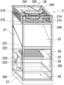
- an outside air conditioner 2 for supplying outside air to the large-scale space S and a package air conditioner 3, which is an air conditioner whose target area is mainly the stand portion 12, are installed.
- the outdoor air conditioner 2 is installed indoors, and includes a heat exchanger 22, an air supply filter 23, and an air supply fan 24 inside a housing 21.
- the detailed structure of the outdoor air conditioner 2 will be described below with reference to FIGS. 2 to 4.
- FIG. 1 The detailed structure of the outdoor air conditioner 2 will be described below with reference to FIGS. 2 to 4.
- the outdoor air conditioner 2 is not necessarily limited to the indoor installation type described in detail below. type, or a natural air supply type that does not have a forced air supply device such as a fan.
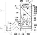
- the housing 21 is erected on a base 27 made of stainless steel installed on the installation surface, and is formed of a heat-insulating panel in the shape of a substantially rectangular prism that is vertically long.
- An inlet 211 for introducing the outside air A is formed on the lower side of one side of the housing 21, and an air supply port 214 for supplying the outside air A introduced from the inlet 211 toward the room is formed on the upper side. It is Although the internal structure of the outdoor air conditioner 2 cannot be visually recognized from the outside, for convenience of explanation, FIGS.
- the housing 21 does not necessarily have to be made up of heat insulating panels. However, by configuring the housing 21 with heat insulating panels, it is possible to prevent the occurrence of dew condensation due to the temperature difference between the inside and outside of the housing 21, and to prevent malfunctions caused by dew condensation in each device housed inside the housing 21. can be prevented.
- the housing 21 does not necessarily have to be installed via the base 27 with respect to the installation surface. However, by installing the housing 21 on the base 27, there is no need to adjust the horizontal position or the vertical position of the housing 21 with respect to the installation surface. become a thing. In addition, since the horizontal position and vertical position of the housing 21 can be maintained, for example, the air supply fan 24, which will be described later, can be properly driven, and the condensed water from the heat exchanger 22 is discharged vertically downward. can be made
- the material of the base 27 does not have to be stainless steel.
- the material of the base 27 does not have to be stainless steel.
- the surface is prevented from being stained and is less likely to be scratched, resulting in a good external appearance.
- the shape of the housing 21 does not necessarily have to be a substantially quadrangular prism. It may have a shape such as a prism other than a quadrangular prism or a cylinder.
- the inlet 211 is connected by a duct 4 to a through hole 5 formed in the wall surface 14 near the rear passage 18 of the upper floor where the outdoor air conditioner 2 is installed, and fresh outdoor air A is always supplied to the housing through the duct 4. It is adapted to be introduced inside the body 21 .
- a mesh inlet filter 25 is installed in the inlet 211 .
- the inlet filter 25 is a filter for trapping substances having relatively large particle diameters, such as insects and dust, which mainly enter the inside of the housing 21 together with the outside air A. As shown in FIG.
- the inlet filter 25 it is not always necessary to install the inlet filter 25. However, by installing the inlet filter 25, as described above, it is possible to keep the inside of the housing 21 clean, and the inside of the housing 21 can be kept clean. It is possible to prevent failures caused by insects and dust entering various devices that are connected to the device.
- the inlet filter 25 may have deodorizing and antibacterial functions by applying a predetermined coating to the filter, in addition to the purpose of preventing insects and dust.
- the mesh shape and mesh size of the inlet filter 25 can also be appropriately changed according to the purpose.
- an outside air introduction path 216 is formed along the vertical direction of the housing 21 for guiding the outside air A introduced from the introduction port 211 to the air supply port 214 .
- the crossing angle between the direction in which the outside air A is introduced and the axial direction of the outside air introduction passage 216 is approximately 90 degrees.
- the outside air introduction passage 216 is partitioned by a partition plate 28 into a first partitioned chamber R1 on the upstream side (introduction port 211 side) and a second partitioned chamber R2 on the downstream side (air supply port 214 side).
- An opening 29 is formed in the approximate center of the partition plate 28, and the first partitioned chamber R1 and the second partitioned chamber R2 are communicated in both directions through the opening 29.
- a heat exchanger 22, which will be described later, is installed so as to face the first compartment R1.
- the partition plate 28 by partitioning the outside air introduction path 216 into the first compartment R1 and the second compartment R2 by the partition plate 28, the entire amount of the outside air A introduced from the introduction port 211 is heated by the heat exchanger 22. It can be exchanged and flowed into the second compartment R2. Also, the outside air A introduced into the first compartment R1 from the inlet 211 collides with the partition plate 28 to change the direction of flow, and the outside air A is brought into a turbulent state in the first compartment R1. be able to. The turbulent outside air A can further promote heat exchange by the heat exchanger 22 installed in the first compartment R1.
- the heat exchanger 22 can exchange heat with the outside air A introduced into the inlet 211.
- the heat transfer tube 221 has a meandering shape in which straight portions and folded portions are alternately continuous, and the heat transfer tube 221 It is a so-called fin tube type consisting of a plurality of fins 222 intersecting with each other.
- the heat exchanger 22 is fixed to the partition plate 28 via known fixing means such as a mounting stay so that the main body portion composed of the heat transfer tubes 221 and the fins 222 corresponds to the opening hole 29 of the partition plate 28. .
- the heat exchanger 22 is positioned at approximately 65 degrees (approximately 25 degrees with respect to the horizontal axis) toward the introduction port 211 with respect to the vertical axis direction of the housing 21 (the axial direction of the outside air introduction passage 216). is fixed inside the housing 21 so as to have an inclination angle of .
- the heat exchanger 22 does not necessarily have to be fixed so that the main body including the heat transfer tubes 221 and the fins 222 corresponds to the opening 29 of the partition plate 28 .
- the outside air A heat-exchanged by the heat exchanger 22 passes through the opening formed in the main body to the opening holes 29. Therefore, the efficiency of inflow of outside air A from the first compartment R1 to the second compartment R2 can be enhanced.
- the heat exchanger 22 does not necessarily need to be installed on the first compartment R1 side. However, by installing the heat exchanger 22 on the first compartment R1 side, the entire amount of the outside air A can be heat-exchanged by the heat exchanger 22, and all of the condensed water dripping from the heat exchanger 22 can be removed. Since the condensed water is dripped onto the water receiving portion 261, which will be described later, the condensed water does not accumulate inside the housing 21, and malfunctions of the internal devices caused by the condensed water can be prevented.
- the heat exchanger 22 does not necessarily have to be installed at a predetermined angle of inclination with respect to the vertical axis direction of the housing 21 .
- the heat exchanger 22 can be installed in a limited space. 21 can be prevented from increasing in size.
- the heat exchanger 22 by installing the heat exchanger 22 at a predetermined inclination angle, it is possible to achieve a rectifying effect for guiding the outside air A introduced from the inlet 211 into a vertically upward flow within the housing 21 . can be done. Further, during the cooling operation of the packaged air conditioner 3, the condensed water adhering to the heat exchanger 22 can be drained smoothly along the inclination of the fins of the heat exchanger 22. - ⁇ As a result, it is possible to prevent stagnation due to the surface tension of condensed water and water droplets from narrowing the air circulation portion of the heat exchanger 22 and stagnation of the air flow.
- the installation angle of the heat exchanger 22 with respect to the vertical axis direction is not necessarily limited to approximately 65 degrees on the introduction port 211 side. It suffices if the entire amount of the outside air A introduced from the inlet 211 can be efficiently passed through the heat exchanger 22. can be changed as appropriate within the range of the inclination angle.
- the heat exchanger 22 has a first inlet/outlet pipe 223 and a second inlet/outlet pipe 224 connected to the heat transfer pipes 221 .
- the ends of the first inlet/outlet pipe 223 and the second inlet/outlet pipe 224 protrude outside the housing 21, and the second refrigerant pipe 332 in the heat medium circuit 33 connected to the packaged air conditioner 3 via a joint, and It can be connected to and removed from the third refrigerant pipe 333 .
- the heat exchanger 22 circulates the refrigerant supplied from the outdoor unit 32 of the packaged air conditioner 3 through the heat medium circuit 33, and can exchange heat with the outside air A. ing.
- the supply of this refrigerant starts when the packaged air conditioner 3 starts operating, and stops when the packaged air conditioner 3 stops operating. That is, since the heat exchanger 22 is operated in conjunction with the operation of the package air conditioner 3, it has a structure that does not require a separate new power source.
- the outside air A introduced from the inlet 211 of the outside air conditioner 2 is cooled to a predetermined temperature by the heat exchanger 22, and the cooled outside air A is Air is supplied from the air supply port 214 . Therefore, the operating time of the packaged air conditioner 3 until reaching the set target temperature of the packaged air conditioner 3 is shortened, and the operating load of the packaged air conditioner 3 can be reduced.
- the packaged air conditioner 3 when the packaged air conditioner 3 is in a heating operation, the outside air A introduced from the inlet 211 of the outside air conditioner 2 is heated to a predetermined temperature by the heat exchanger 22, and the heated outside air A is supplied. Air is supplied from the air port 214 . Therefore, as in the cooling operation, the operation time of the packaged air conditioner 3 until reaching the set target temperature of the packaged air conditioner 3 is shortened, and the operating load of the packaged air conditioner 3 can be reduced.
- the outside air A is supplied from the air supply port 22 without being cooled or heated by the heat exchanger 22 .
- the outside air A supplied from the outside air conditioner 2 is supplied to the large-scale space S after being controlled to an appropriate temperature according to the operation mode of the package air conditioner 3. can be kept constant at all times.
- the air supply filter 23 is a filter device for purifying the outside air by trapping contaminants (pollen and PM2.5) contained in the outside air introduced from the inlet 211 .
- the air supply filter 23 is inclined at a predetermined angle (approximately 45° ) on the downstream side of the heat exchanger 22 and in the second compartment R2.
- the air supply filter 23 does not necessarily have to be installed at a predetermined inclination angle with respect to the vertical axis direction of the housing 21 .
- the air supply filter 23 can be installed in a limited space. can prevent erosion.
- the installation angle of the air supply filter 23 with respect to the vertical axis direction is not necessarily limited to approximately 45 degrees on the introduction port 211 side.
- the inclination angle can be changed appropriately in the range of about 30 degrees to 60 degrees toward the inlet 211 side with respect to the vertical axis direction of the housing 21. can be done.
- the inlet filter 25 described above is a filter intended to trap relatively large particle size substances (insects and dust) contained in the outside air A, but the inlet filter 23 traps The mesh size of the filter is smaller than that of the inlet filter 25 because it is intended to capture fine particles that cannot be filtered.
- An air supply chamber 212 is formed by a ceiling plate 213 in the upper part of the housing 21 .
- a communication hole (not numbered) is formed in the ceiling plate 213 so that the outside air A can communicate between the outside air introduction path 216 and the air supply chamber 212 .
- an air supply port 214 for blowing out the outside air A toward the room is formed at a total of three locations, the front side and the left and right side sides of the side surface of the housing.
- the outside air A introduced into the body 21 can be supplied from the air supply port 214 in three directions.
- a plurality of wind direction plates 215 are installed at the air supply port 214 at predetermined intervals.
- the wind direction plate 215 does not necessarily have to be installed. However, by installing the wind direction plate 215, the directivity of the outside air A at the time of air supply can be improved, so that the outside air A can easily spread throughout the large-scale space S, and the room can be ventilated in a short time. .
- An air supply fan 24 is installed in the air supply chamber 212 to generate an air flow from the introduction port 211 to the air supply port 214 along the outside air introduction path 216 .
- the air supply fan 24 includes fan blades 243 , a motor (not shown) for driving the fan blades 243 , a main body 241 housing the fan blades 243 and the motor, and a nozzle 244 connected to the main body 241 . ing.
- the fan blades 243 are configured such that, for example, the sirocco fan, the wind tunnel surrounding the sirocco fan, and the casing can be separated, so that the sirocco fan that needs to be replaced periodically can be easily replaced. ing.
- a main body 241 of the air supply fan 24 is suspended from the ceiling surface of the housing 21 by a fixing bracket 242, and is connected to a switch for turning on the power to the motor and a controller for setting the rotation speed of the motor.
- the motor rotates at the rotation speed set by the controller 246, and the fan blades 243 connected to the motor are driven.
- the number of rotations of the motor is set to approximately 2200 to 2300 rpm in normal operation, but is not limited to this. Based on the number of installed outdoor air conditioners 2, etc., it is possible to appropriately change so as to obtain the required ventilation volume.
- a drain section 26 is installed vertically below the heat exchanger 22 to receive condensed water generated in the heat exchanger 22 and discharge it to the outside of the outside air conditioner 2 .
- the drain portion 26 includes a water receiving portion 261 for receiving condensed water dripped from the heat exchanger 22, a trap portion 263 for storing the condensed water dripped into the water receiving portion 261, and guiding the water from the water receiving portion 261 to the trap portion 263. It is composed of a drainage channel 262 for
- a drain hole 264 communicating with a drainage channel 262 is formed at a predetermined position in the water receiving portion 261, and a slope having a predetermined inclination angle is formed toward the drain hole 264. Therefore, all of the condensed water dripped onto the water receiving portion 261 is drained from the drain hole 264 to the drainage channel 262 through the slope.
- the trap part 263 is installed on the side surface of the housing 21 and has a predetermined volume for temporarily storing the condensed water drained through the drainage channel 262 .
- the trap portion 263 has an operation portion that can open and close a discharge hole (not shown) by, for example, pushing and pulling operations. Condensed water can be discharged outside the machine.
- One of the sides of the housing has a door structure that can be opened and closed, and at the time of maintenance of the outdoor air conditioner 2, opening the door makes it easy to repair the equipment inside and replace parts. It is possible to do
- the outdoor air conditioner 2 when installed in the rear passage 18, it may be connected to a fixed object 6 such as a pillar with a connecting member 7, as shown in FIG.
- a fixed object 6 such as a pillar with a connecting member 7, as shown in FIG.
- the packaged air conditioner 3 has an indoor unit 31 installed in the rear passage 18 of the stand part 12 and an outdoor unit 32 installed outdoors.
- the heat medium circuit 33 is composed of a first refrigerant circuit 331, a second refrigerant circuit 332, and a third refrigerant circuit 333. are directly connected by the refrigerant circuit of Also, as described above, the indoor unit 31 and the outdoor air conditioner 2 are connected by the second refrigerant pipe 332 , and the outdoor air conditioner 2 and the outdoor unit 32 are connected by the third refrigerant circuit 333 .
- the package air conditioner 3 does not necessarily have to consist of the indoor unit 31 and the outdoor unit 32. As long as the package air conditioner 3 has the heat medium circuit 33, for example, a package air conditioner without the outdoor unit 32 can be installed.
- the heat exchanger 22 of the outdoor air conditioner 2 does not necessarily have to be connected to the heat medium circuit 33 of the packaged air conditioner 3 .
- it may be connected to a heat medium circuit (not shown) of the radiation panel 8, or may be connected to a heat medium circuit of a separately provided cooling water circulation device.
- the heat source device connected to the heat exchanger 22 is not particularly limited.
- the exhaust part 9 is composed of a floor surface exhaust hole 91 , a wall surface exhaust hole 92 and an exhaust guide path 93 .
- the floor surface exhaust holes 91 are formed in the floor surface portion 13 of the facility 1 along the inner wall surface 16 at regular intervals.
- the wall surface portion 14 is formed with wall surface exhaust holes 92 communicating with the outside corresponding to the number of the floor surface exhaust holes 91 .
- the floor exhaust hole 91 and the wall surface exhaust hole 92 are in communication with each other through an exhaust guide path 93, and the inside air of the large-scale space S flowing into the floor exhaust hole 91 is installed in the exhaust guide path 93. The air is forcibly exhausted to the outside of the facility 1 through the wall exhaust hole 92 through the exhaust air blower 94 .
- the outside air A is forcibly supplied to the large-scale space S by the outside air conditioner 2, and the outside air A supplied to the large-scale space S is supplied by the exhaust blower 94.
- a type 1 ventilation system is adopted in which the air is forcibly exhausted outdoors.
- the installation position of the exhaust air blower 94 in the exhaust guide path 93 may be provided at a predetermined position of either the floor surface exhaust hole 91 or the wall surface exhaust hole 92 .
- the positional relationship between the air supply unit and the floor exhaust holes 91 does not necessarily have to be the layout described above. However, by arranging the floor surface exhaust holes 91 on the center line of the adjacent air supply units in plan view, the outside air A supplied from the outside air conditioner 2 is most efficiently discharged from the floor surface exhaust holes 91. be able to.
- outside air A is supplied toward the arena section 11 from the outside air conditioner 2 installed in the rear passage 18 of the stand section 12 on the upper floor.
- the temperature and humidity of the outside air A are adjusted by passing through the heat exchanger 22 of the outside air conditioner 2 .
- the outside air A is divided into a horizontal flow directed toward the upper space of the stand portion 12 and an obliquely downward flow directed toward the floor exhaust hole 91 along the stand portion 12 by the diffusion effect.
- the obliquely downward flow along the stand portion 12 is quickly exhausted to the outside through the floor exhaust holes 91 together with contaminants including exhaled air generated in the stand portion 11, for example.
- the outside air conditioners 2 are provided at positions facing each other, among the flows of the outside air A supplied from each of the outside air conditioners 2, the horizontal flows F1 and F2 are large. Collision near the approximate center of the scale space S. After that, the direction of the outside air A changes vertically downward, and the outside air A that has reached the floor portion 13 forms a flow toward the floor surface exhaust hole 91 due to the negative pressure effect of the exhaust blower 94 . At this time, the contaminants generated in the arena section 11 are combined with the outside air A flowing from the upper layer, and are quickly exhausted to the outside through the floor exhaust holes 91 .
- air containing contaminants including exhaled air in the arena section 11 is constantly supplied as fresh air under pressure downward from the upper part of the arena section 11 toward the floor section 13, and the effect of instantaneous uniform diffusion is utilized. , Since the air flows toward the floor surface exhaust hole 91, it suppresses the floating of micro droplets etc. when using the arena section 11, making it an effective ventilation system for infection prevention measures in the large-scale space S. .
- the ventilation device and the ventilation method according to the present invention can efficiently ventilate the user's active area in an indoor facility having a large space and realize a comfortable environment. .
Abstract
[Problem] To provide a ventilation system and a ventilation method for efficiently ventilating an activity region of users in an indoor facility having a large space, and realizing a comfortable environment. [Solution] The present invention is a ventilation system installed in a facility in which a large space is formed, the ventilation system being constituted by a package air-conditioner 3 having a heat transfer medium circuit 33 in which a refrigerant circulates, an outside air conditioning machine 2 having a heat exchanger 22 incorporated into the heat transfer medium circuit 33, and a discharge unit 9 for discharging outside air A that has circulated in the facility 1 to the outside. The package air-conditioner 3 and the outside air conditioning machine 2 are installed on an upper floor, and the discharge unit 9 is installed on a lower floor. Outside air A introduced from the outside air conditioning machine 2 on the upper floor circulates through the large space S and is then discharged to the outside from the discharge unit 9, whereby the large space S is constantly ventilated by fresh air.
Description
本発明は、換気システム、及び換気方法に関する。詳しくは、大規模空間を有する屋内施設における利用者の活動領域を効率的に換気し、快適な環境を実現する換気システム、及び換気方法に関するものである。
The present invention relates to a ventilation system and a ventilation method. More specifically, the present invention relates to a ventilation system and a ventilation method that efficiently ventilate user activity areas in an indoor facility having a large space and realize a comfortable environment.
近年、建造物の高気密化・高断熱化が進み、十分な換気を行わないと二酸化炭素濃度が高くなり、特に新設の建造物などではホルムアルデヒドや揮発有機化合物(VOC:Vapor Organic Composition)の濃度が高くなりすぎることがある。また、不十分な換気により湿度が高くなってカビやダニが発生し、アレルギーを引き起こす原因ともなっている。
In recent years, buildings have become highly airtight and highly insulated, and without sufficient ventilation, the concentration of carbon dioxide will increase, especially in newly constructed buildings, the concentration of formaldehyde and volatile organic compounds (VOC: Vapor Organic Composition). can be too high. Insufficient ventilation also increases the humidity, causing mold and mites to grow, which is a cause of allergies.
建造物の中でも、体育館をはじめとする大規模空間を有する屋内施設は、各種運動競技を行う場であるとともに、非常災害時には地域住民の応急避難場所として重要な役割を担っている。特に、近年では、新型コロナウイルスを始めとする感染症予防の対策として、居住空間内に定期的に外気を取り入れ、換気の悪い密閉空間をできるだけ避けることが推奨されている。このような密閉空間内における空気汚染に対処するために、建造物全体を対象として一定量の空気を24時間換気し続ける24時間換気システムが採用されている。
Among buildings, indoor facilities such as gymnasiums, which have large spaces, are places where various sports are held, and also play an important role as emergency evacuation sites for local residents in the event of an emergency disaster. In recent years, in particular, as a measure to prevent infectious diseases such as the new coronavirus, it has been recommended to regularly introduce outside air into living spaces and avoid closed spaces with poor ventilation as much as possible. In order to deal with air pollution in such closed spaces, a 24-hour ventilation system is adopted, which continuously ventilates the entire building with a constant amount of air for 24 hours.
大規模空間を有する施設において採用されている換気システムとしては、例えば2階部分に形成された換気窓から外気を流入させ、大規模空間を循環した内気を1階部分に形成された換気窓から屋外へ排気させるといった自然換気方法が採用されている。
As a ventilation system adopted in a facility with a large space, for example, the ventilation window formed on the second floor allows outside air to flow in, and the inside air that circulates in the large space flows through the ventilation window formed on the first floor. Natural ventilation methods such as exhausting air to the outside are adopted.
一方、大規模空間における換気促進を目的として、機械換気による強制的な換気システムも数多く提案されている。機械換気を採用した換気システムとしては、給気用送風機によって外気を室内に強制的に取り入れ、かつ排気用送風機によって内気を屋外へ強制的に排気する第1種換気方式と、給気用送風機によって強制的に給気した外気を自然排気する第2種換気方式と、自然給気によって大規模空間に給気した外気を排気用送風機によって屋外へ強制的に排気する第3種換気方式がある。
On the other hand, for the purpose of promoting ventilation in large spaces, many forced ventilation systems using mechanical ventilation have been proposed. As a ventilation system that uses mechanical ventilation, there is a type 1 ventilation system that forcibly takes in outside air into the room with an air supply fan and forcibly exhausts the inside air to the outside with an exhaust fan. There are a second type ventilation system that naturally exhausts the forcibly supplied outside air, and a third type ventilation system that forcibly exhausts the outside air supplied to the large space by the natural supply to the outside using an exhaust fan.
例えば、特許文献1には、大規模空間における空調の効率を高めるための第1種換気方式を採用した換気システムが開示されている。具体的には、外気を導入する給気用送風機を空調対象となる大規模空間の床面付近の高さ位置に設置するとともに、室内の空気を屋外に排気する排気用送風機を大規模空間の壁面であって天井までの高さの50%以上の高さに設置する。
For example, Patent Document 1 discloses a ventilation system that employs a type 1 ventilation system to increase the efficiency of air conditioning in a large space. Specifically, the air supply fan that introduces outside air is installed at a height near the floor of the large-scale space to be air-conditioned, and the exhaust fan that exhausts indoor air to the outside is installed in the large-scale space. Install on the wall at a height of 50% or more of the height to the ceiling.
このような構成により、太陽光により暖められた天井付近に滞留する高温空気が徐々に下降する途中において排気用送風機を通じて屋外に排気されるため、高温空気が大規模空間の床面まで下降することを防止できる。従って、室内で活動する利用者の活動領域の温度上昇を抑制し、さらに大規模空間の下部には給気用送風機から外気が導入されるため、活動領域における換気も促進することができる。
With this configuration, the hot air that stays near the ceiling and is warmed by sunlight is exhausted to the outside through the exhaust fan while it is gradually descending, so that the hot air can descend to the floor surface of the large-scale space. can be prevented. Therefore, it is possible to suppress the temperature rise in the activity area of users who are active indoors, and to promote the ventilation in the activity area because the outside air is introduced from the air supply blower to the lower part of the large-scale space.
前記した特許文献1によれば、排気用送風機を任意の位置に設置することにより、大規模空間の換気促進と空気調和機の効率化を実現できるものとなっている。一方、特許文献1に係る換気システムにおいては、外気がそのまま給気用送風機を通じて室内に流れ込むため、例えば外気温の低い冬場においては、低温の外気がそのまま室内に流入することになる。
According to the above-mentioned Patent Document 1, by installing an exhaust fan in an arbitrary position, it is possible to promote ventilation in a large-scale space and improve the efficiency of the air conditioner. On the other hand, in the ventilation system according to Patent Document 1, outside air flows directly into the room through the air supply blower, so in winter when the outside temperature is low, for example, low-temperature outside air flows into the room.
さらに、給気用送風機が屋内施設の床面付近に設けられているため、室内に流入した低温の外気は天井方向に上昇することなく屋内施設の利用者の活動領域である床面付近に滞留することになる。そのため、活動領域における温度下降や換気ムラが生じ、利用者にとって活動環境が悪化することが懸念される。
In addition, since the air supply fan is installed near the floor of the indoor facility, the low-temperature outside air that flows into the room stays near the floor, which is the activity area of the indoor facility users, without rising toward the ceiling. will do. As a result, there is concern that temperature drop and ventilation irregularities will occur in the activity area, and that the activity environment for the user will deteriorate.
以上のような問題に対処するために、大規模空間の空調を行うべく空気調和機を運転すると、給気用送風機により常時低温の外気が室内に流入する状況においては、空気調和機の運転負荷が大きくなるとともに、大規模空間の温度を目標温度まで上げるには長時間を要するものとなる。
In order to deal with the above problems, when an air conditioner is operated to air-condition a large space, the operating load of the air conditioner is increases, it takes a long time to raise the temperature of the large-scale space to the target temperature.
本発明は、以上の点を鑑みて創案されたものであり、大規模空間を有する屋内施設における利用者の活動領域を効率的に換気し、快適な環境を実現する換気システム、及び換気方法を提供することを目的とするものである。
The present invention has been invented in view of the above points, and provides a ventilation system and a ventilation method that efficiently ventilate the user's active area in an indoor facility having a large space and realize a comfortable environment. It is intended to provide
前記の目的を達成するために、本発明の換気システムは、上層階の空間と下層階の空間とが連続する吹き抜け構造であり、床面部、天井面部、及び壁面部により囲まれた大規模空間が形成された施設に設置される換気システムであって、冷媒が循環する熱媒体回路を有する熱源装置と、前記上層階に設置され、導入口から導入された外気を前記大規模空間に給気する給気口に通じる外気導入路が形成された筐体、前記熱媒体回路の経路上に設置され、前記導入口から導入された外気を冷却または加熱する熱交換器を有する外気調和機と、前記床面部の所定の位置に形成された床面排気孔、前記下層階の前記壁面部の所定の位置に形成され屋外と連通する壁面排気孔、前記床面排気孔から前記壁面排気孔に連通する排気誘導路から構成された排気部とを備える。
In order to achieve the above object, the ventilation system of the present invention has an atrium structure in which the space on the upper floor and the space on the lower floor are continuous, and is a large-scale space surrounded by a floor surface, a ceiling surface, and a wall surface. A ventilation system installed in a facility where a is formed, comprising a heat source device having a heat medium circuit in which a refrigerant circulates, and a heat source device installed on the upper floor and supplying outside air introduced from an inlet to the large space. An outside air conditioner having a housing in which an outside air introduction path leading to an air supply port is formed, and a heat exchanger installed on the path of the heat medium circuit and cooling or heating the outside air introduced from the introduction port; A floor surface exhaust hole formed at a predetermined position on the floor surface, a wall surface exhaust hole formed at a predetermined position on the wall surface portion of the lower floor and communicating with the outside, and the floor surface exhaust hole communicating with the wall surface exhaust hole. and an exhaust portion configured from an exhaust guide path for exhaust gas.
ここで、冷媒が循環する熱媒体回路を有する熱源装置を備えることにより、例えば熱源装置として空気調和機や冷却水循環装置の熱媒体回路(例えば、フロンガスや代替ガス等の冷媒、温水または冷水、加熱または冷却用のガス等が含まれる。)に、後記する外気調和機の熱交換器を組み込むことで、外気調和機に導入された外気が熱交換された後に大規模空間に向けて給気することができる。
Here, by providing a heat source device having a heat medium circuit in which a refrigerant circulates, for example, a heat medium circuit of an air conditioner or a cooling water circulation device as a heat source device (for example, refrigerant such as freon gas or alternative gas, hot water or cold water, heating or gas for cooling, etc.), by incorporating the heat exchanger of the outside air conditioner described later, the outside air introduced into the outside air conditioner is heat-exchanged and then supplied to the large-scale space. be able to.
また、上層階に設置され、導入口から導入された外気を大規模空間に給気する給気口に通じる外気導入路が形成された筐体、熱媒体回路の経路上に設置され、導入口から導入された外気を冷却または加熱する熱交換器を有する外気調和機調和機を備えることにより、外気を大規模空間に給気して換気を促進することができる。そして、熱交換器が熱源装置の熱媒体回路に組み込まれていることにより、熱源装置の運転と連動して供給される熱媒体によって、外気調和機に導入された外気が熱交換され、熱交換後の外気を大規模空間に給気することができるため、大規模空間の温度を適温に保つことが可能となる。
In addition, the housing is installed on the upper floor and has an outside air introduction path leading to the air supply port that supplies the outside air introduced from the introduction port to the large-scale space. By providing an outside air conditioner with a heat exchanger that cools or heats the outside air introduced from the outside air conditioner, the outside air can be supplied to the large space to facilitate ventilation. Since the heat exchanger is incorporated in the heat medium circuit of the heat source device, the outside air introduced into the outside air conditioner is heat-exchanged by the heat medium supplied in conjunction with the operation of the heat source device. Since the subsequent outside air can be supplied to the large-scale space, it is possible to keep the temperature of the large-scale space at an appropriate temperature.
さらに、外気調和機により温度調整した外気温が大規模空間に給気されることにより、外気の温度(湿度)と大規模空間内の温度(湿度)との間に差が生じるため、瞬時拡散効果により大規模空間の全体に外気を循環させることができる。
Furthermore, when the outside air temperature adjusted by the outside air conditioner is supplied to the large-scale space, a difference occurs between the temperature (humidity) of the outside air and the temperature (humidity) inside the large-scale space. As a result, the outside air can be circulated throughout a large-scale space.
また、床面部の所定の位置に形成された床面排気孔、下層階の壁面部の所定の位置に形成され屋外と連通する壁面排気孔、床面排気孔から壁面排気孔に連通する排気誘導路から構成された排気部を備えることにより、外気調和機から給気された外気は大規模空間を循環した後に床面排気孔から排気される。そして、床面排気孔から排気された外気は、排気誘導路を通じて壁面排気孔を通じて屋外に排気される。なお、排気部の所定の位置に排気用送風機を設置することで、強制的に排気する第1種換気方式とすることも可能である。
In addition, a floor exhaust hole formed at a predetermined position on the floor surface, a wall exhaust hole formed at a predetermined position on the wall surface of the lower floor and communicating with the outside, and an exhaust guide communicating from the floor surface exhaust hole to the wall exhaust hole By providing the exhaust part composed of the channel, the outside air supplied from the outside air conditioner circulates in the large-scale space and is then exhausted from the floor surface exhaust hole. The outside air exhausted from the floor surface exhaust hole is exhausted to the outside through the wall surface exhaust hole through the exhaust guide path. By installing an exhaust blower at a predetermined position of the exhaust section, it is possible to adopt a first-class ventilation system that forcibly exhausts air.
ここで、大規模空間を有する多くの施設は床下空間が形成されているが、この床下空間に湿気が溜まることにより床面部の膨張や収縮が生じる。この点、床面排気孔から壁面排気孔に連通する排気誘導路を形成することにより、床下空間内の通気性を確保することで床下空間に湿気が溜まることが防止される。
Here, many facilities with large-scale spaces have underfloor spaces, but the accumulation of moisture in this underfloor space causes the floor surface to expand and contract. In this respect, by forming an exhaust guide path that communicates from the floor surface exhaust hole to the wall surface exhaust hole, ventilation in the underfloor space is ensured, thereby preventing moisture from accumulating in the underfloor space.
また、熱源装置は上層階に設置され、上層階の所定の領域を空調対象とする空気調和機である場合には、空気調和機により大規模空間を所定の温度に保つことができる。また、前記の通り、外気調和機から給気される外気は熱交換において所定の温度に冷却、又は加熱された後に大規模空間に向けて給気されることにより、空気調和機の設定した目標温度に達するまでの空気調和機の稼動時間が短時間となり、空気調和機の運転負荷を低減することができる。
In addition, if the heat source device is installed on the upper floors and the air conditioner is used to air-condition a predetermined area of the upper floors, the air conditioner can maintain the large-scale space at a predetermined temperature. In addition, as described above, the outside air supplied from the outside air conditioner is cooled or heated to a predetermined temperature in heat exchange and then supplied toward the large space, so that the target set by the air conditioner The operation time of the air conditioner until reaching the temperature is shortened, and the operating load of the air conditioner can be reduced.
また、外気調和機と空気調和機とを一組の給気ユニットとして、該給気ユニットが所定の間隔で並設されている場合には、大規模空間の大きさに応じて複数の給気ユニットを設けることで、大規模空間を適温に保つことができるとともに短時間で換気を行うことができる。さらに、外気調和機と空気調和機とを近接して配置することで、空気調和機の熱媒体回路に外気調和機の熱交換器を簡単に組み込むことができる。
In addition, when an outside air conditioner and an air conditioner are set as a set of air supply units, and the air supply units are arranged side by side at predetermined intervals, a plurality of air supply units may be provided according to the size of the large-scale space. By installing a unit, it is possible to keep a large space at an appropriate temperature and to ventilate it in a short time. Furthermore, by arranging the outside air conditioner and the air conditioner close to each other, the heat exchanger of the outside air conditioner can be easily incorporated into the heat medium circuit of the air conditioner.
また、床面排気孔は、大規模空間の平面視において、隣接する給気ユニットの中心線上に位置する場合には、大規模空間の全体に循環された外気を最も効率的に屋外に排気することができるため、換気効率を高めることができる。
In addition, when the floor exhaust hole is positioned on the center line of the adjacent air supply unit in a plan view of the large-scale space, the outside air circulated throughout the large-scale space is most efficiently exhausted to the outside. Therefore, ventilation efficiency can be improved.
また、空気調和機は、熱媒体回路により接続された室内機、及び室外機を有し、熱媒体回路は、室外機から室内機に冷媒を送る第1の冷媒配管と、室内機から外気調和機に冷媒を送る第2の冷媒配管と、外気調和機から室外機に冷媒を送る第3の冷媒配管とを有する場合には、簡単な配管構造により空気調和機と外気調和機を一体化することができる。
Further, the air conditioner has an indoor unit and an outdoor unit connected by a heat medium circuit, and the heat medium circuit includes a first refrigerant pipe for sending refrigerant from the outdoor unit to the indoor unit, When the second refrigerant pipe for sending the refrigerant to the outdoor unit and the third refrigerant pipe for sending the refrigerant from the outdoor air conditioner to the outdoor unit are provided, the air conditioner and the outdoor air conditioner can be integrated with a simple pipe structure. be able to.
以上のような構成により、まず冷房運転時には、室外機の減圧器で低温の液体になった冷媒が第1の冷媒配管を通じて室内機に送られ、室内機の熱交換器を冷却する。そして室内機の熱交換器を冷却した冷媒の一部は第2の冷媒配管を通じて外気調和機に送られ、外気調和機の熱交換器を冷却する。その後、冷媒は第3の冷媒配管を通じて室外機に再び戻り、減圧器で低温の液体となって第1の冷媒配管に送られる。このサイクルを繰り返すことで、室内機、及び外気調和機の熱交換器は効率的に冷却され、大規模空間の換気を促進するとともに大規模空間の室内温度を目標温度に保つことができる。
With the above configuration, first, during cooling operation, the refrigerant that has become a low-temperature liquid in the pressure reducer of the outdoor unit is sent to the indoor unit through the first refrigerant pipe to cool the heat exchanger of the indoor unit. Part of the refrigerant that has cooled the heat exchanger of the indoor unit is sent to the outside air conditioner through the second refrigerant pipe to cool the heat exchanger of the outside air conditioner. After that, the refrigerant returns to the outdoor unit again through the third refrigerant pipe, becomes a low-temperature liquid in the decompressor, and is sent to the first refrigerant pipe. By repeating this cycle, the heat exchangers of the indoor unit and the outdoor air conditioner are efficiently cooled, promoting ventilation of the large-scale space and keeping the indoor temperature of the large-scale space at the target temperature.
一方、暖房運転時には、前記した冷房運転時と逆のサイクルとなる。即ち、室外機で高温の気体となった冷媒が第3の冷媒配管を通じて外気調和機に送られ、冷媒の熱により外気調和機の熱交換器が温められる。さらに、冷媒は第2の冷媒配管を通じて室内機に送られ、室内機の熱交換器を温めた後に第1の冷媒配管を通じて室外機に再び戻り、圧縮器で高温の気体となって第3の冷媒配管に送られる。このサイクルを繰り返すことで、室内機、及び外気調和機の熱交換器は効率的に温められ、大規模空間の換気を促進するとともに大規模空間の温度を目標温度に保つことができる。
On the other hand, during heating operation, the cycle is opposite to that during cooling operation described above. That is, the refrigerant that has become a high-temperature gas in the outdoor unit is sent to the outdoor air conditioner through the third refrigerant pipe, and the heat of the refrigerant warms the heat exchanger of the outdoor air conditioner. Furthermore, the refrigerant is sent to the indoor unit through the second refrigerant pipe, warms the heat exchanger of the indoor unit, returns to the outdoor unit through the first refrigerant pipe, becomes a high-temperature gas in the compressor, and becomes a third It is sent to the refrigerant piping. By repeating this cycle, the heat exchangers of the indoor unit and the outdoor air conditioner are efficiently warmed, promoting ventilation of the large-scale space and maintaining the temperature of the large-scale space at the target temperature.
また、下層階には床面部を含むアリーナ部が形成されるとともに、アリーナ部を空調対象とする輻射式パネルが設置され、輻射式パネルは、床面部から上層階に至るまでの高さを有し、壁面部の全周に設置されている場合には、施設の利用者の活動領域であるアリーナ部を常に快適な温度に保つことが可能となる。
In addition, the arena area including the floor area is formed on the lower floors, and radiant panels are installed to air-condition the arena area, and the radiant panels have a height from the floor area to the upper floors. However, if they are installed around the entire circumference of the wall surface, it is possible to keep the arena area, which is the activity area of the facility users, at a comfortable temperature at all times.
さらに、輻射式パネルは送風を発生しないため、例えばアリーナ部において送風による影響を受け易い競技(例えばバトミントンや卓球等)を行う場合においても、送風の影響を受けることなく、アリーナ部の全体を適温に保つことが可能となる。
In addition, since the radiant panel does not generate airflow, even when playing games that are easily affected by airflow in the arena (such as badminton and table tennis), the entire arena is kept at a suitable temperature without being affected by airflow. can be kept at
また、上層階は、背面側である壁面部から前面側に向けて下方に傾斜する階段状のスタンド部であり、スタンド部の前面側には前面通路、背面側には背面通路がそれぞれ形成され、外気調和機は背面通路に設置されている場合には、背面通路から前面側に向けて外気を給気することができるため、大規模空間の全体に外気を循環させることができる。
In addition, the upper floor is a stepped stand that slopes downward from the wall on the back side toward the front side. When the outside air conditioner is installed in the rear passage, the outside air can be supplied from the rear passage toward the front side, so that the outside air can be circulated throughout the large-scale space.
前記の目的を達成するために、本発明の換気システムは、上層階の空間と下層階の空間とが連続する吹き抜け構造であり、床面部、天井面部、及び壁面部により囲まれた大規模空間が形成された施設に設置される換気システムであって、冷媒が循環する熱媒体回路を有する熱源装置と、前記上層階に設置され、前記上層階の前記壁面部の所定の位置に形成された給気孔に接続されたダクト、該ダクトから導入口に導入された外気を前記大規模空間に給気する給気口に通じる外気導入路が形成された筐体、前記熱媒体回路の経路上に設置され前記導入口から導入された外気を冷却または加熱する熱交換器、前記給気口が形成された給気室に配され前記導入口から前記給気口に向かう気流を生成する給気ファン、前記外気導入路上であって、前記熱交換器の下流側に配され、前記導入口から導入された外気を浄化する給気フィルタを有する外気調和機と、前記床面部の所定の位置に形成された床面排気孔、前記下層階の前記壁面部の所定の位置に形成され屋外と連通する壁面排気孔、前記床面排気孔から前記壁面排気孔に連通する排気誘導路から構成された排気部とを備える。
In order to achieve the above object, the ventilation system of the present invention has an atrium structure in which the space on the upper floor and the space on the lower floor are continuous, and is a large-scale space surrounded by a floor surface, a ceiling surface, and a wall surface. A ventilation system installed in a facility where a A duct connected to an air supply port, a housing formed with an outside air introduction path leading to the air supply port for supplying outside air introduced from the duct to the introduction port into the large-scale space, and on the path of the heat medium circuit A heat exchanger that is installed and cools or heats the outside air introduced from the inlet, and an air supply fan that is arranged in an air supply chamber in which the air supply port is formed and generates an air flow from the inlet to the air supply port. an outside air conditioner provided on the outside air introduction passage downstream of the heat exchanger and having a supply air filter for purifying the outside air introduced from the introduction port; a wall surface exhaust hole formed at a predetermined position of the wall surface of the lower floor and communicating with the outside; and an exhaust guide path communicating from the floor surface exhaust hole to the wall surface exhaust hole. and a part.
ここで、冷媒が循環する熱媒体回路を有する熱源装置を備えることにより、例えば熱源装置として空気調和機や冷却水循環装置の熱媒体回路に、後記する外気調和機の熱交換器を組み込むことで、外気調和機に導入された外気が熱交換された後に大規模空間に向けて給気することができる。
Here, by providing a heat source device having a heat medium circuit in which a refrigerant circulates, for example, by incorporating a heat exchanger of an outside air conditioner described later in a heat medium circuit of an air conditioner or a cooling water circulation device as a heat source device, The outside air introduced into the outside air conditioner can be heat-exchanged and then supplied to a large-scale space.
また、上層階に設置された外気調和機を備えることにより、外気調和機に導入した外気を大規模空間に給気することで、大規模空間における換気を促進することができる。
In addition, by installing an outside air conditioner installed on the upper floors, it is possible to promote ventilation in the large space by supplying the outside air introduced into the outside air conditioner to the large space.
また、外気調和機が、上層階の壁面部の所定の位置に形成された給気孔に接続されたダクト、ダクトから導入口に導入された外気を大規模空間に給気する給気口に通じる外気導入路が形成された筐体を有することにより、大規模空間が形成された施設の壁面に接続されたダクトを通じて外気を外気調和機の筐体に導入することができる。
In addition, the outside air conditioner is connected to a duct connected to an air supply hole formed at a predetermined position on the wall surface of the upper floor, and the outside air introduced from the duct to the inlet is connected to the air supply port that supplies the large space. By having the housing in which the outside air introduction path is formed, the outside air can be introduced into the housing of the outside air conditioner through the duct connected to the wall surface of the facility in which the large-scale space is formed.
また、外気調和機が、熱媒体回路の経路上に設置され導入口から導入された外気を冷却または加熱する熱交換器を有することにより、熱源装置の運転と連動して供給される熱媒体によって、外気調和機に導入された外気が熱交換され、熱交換後の外気を大規模空間に給気することができるため、大規模空間の温度を適温に保つことが可能となる。
In addition, since the outside air conditioner has a heat exchanger installed on the path of the heat medium circuit and cooling or heating the outside air introduced from the inlet, the heat medium supplied in conjunction with the operation of the heat source device Since the outside air introduced into the outside air conditioner is heat-exchanged and the outside air after the heat exchange can be supplied to the large-scale space, it is possible to keep the temperature of the large-scale space at an appropriate temperature.
また、外気調和機が、給気口が形成された給気室に配され導入口から給気口に向かう気流を生成する給気ファンを有することにより、より多くの外気を筐体内に導入することができるため、大規模空間における換気を促進することができる。
Further, the outside air conditioner has an air supply fan arranged in the air supply chamber in which the air supply port is formed and generates an air flow from the introduction port toward the air supply port, thereby introducing more outside air into the housing. Therefore, it is possible to promote ventilation in a large-scale space.
また、外気調和機が、外気導入路上であって、熱交換器の下流側に配され、導入口から導入された外気を浄化する給気フィルタを有することにより、筐体内に導入した外気に含まれる汚染物質をはじめとする不純物を捕捉し、常に新鮮な外気を大規模空間に給気することができる。
In addition, the outside air conditioner has an air supply filter that is arranged on the outside air introduction passage and downstream of the heat exchanger and cleans the outside air introduced from the introduction port, so that the outside air introduced into the housing is Contaminants and other impurities that are trapped in the air can be captured, and fresh outside air can always be supplied to the large-scale space.
また、床面部の所定の位置に形成された床面排気孔、下層階の壁面部の所定の位置に形成され屋外と連通する壁面排気孔、床面排気孔から壁面排気孔に連通する排気誘導路から構成された排気部を備えることにより、外気調和機から給気された外気は大規模空間を循環した後に床面排気孔から排気される。そして、床面排気孔から排気された外気は、排気誘導路を通じて壁面排気孔を通じて屋外に排気される。なお、排気部の所定の位置に排気用送風機を設置することで、強制的に排気する第1種換気方式とすることも可能である。
In addition, a floor exhaust hole formed at a predetermined position on the floor surface, a wall exhaust hole formed at a predetermined position on the wall surface of the lower floor and communicating with the outside, and an exhaust guide communicating from the floor surface exhaust hole to the wall exhaust hole By providing the exhaust part composed of the channel, the outside air supplied from the outside air conditioner circulates in the large-scale space and is then exhausted from the floor surface exhaust hole. The outside air exhausted from the floor surface exhaust hole is exhausted to the outside through the wall surface exhaust hole through the exhaust guide path. By installing an exhaust blower at a predetermined position of the exhaust section, it is possible to adopt a first-class ventilation system that forcibly exhausts air.
ここで、大規模空間を有する多くの施設は床下空間が形成されているが、この床下空間に湿気が溜まることにより床面部の膨張や収縮が生じる。この点、床面排気孔から壁面排気孔に連通する排気誘導路を形成することにより、床下空間内の通気性を確保することで床下空間に湿気が溜まることが防止される。
Here, many facilities with large-scale spaces have underfloor spaces, but the accumulation of moisture in this underfloor space causes the floor surface to expand and contract. In this respect, by forming an exhaust guide path that communicates from the floor surface exhaust hole to the wall surface exhaust hole, ventilation in the underfloor space is ensured, thereby preventing moisture from accumulating in the underfloor space.
前記の目的を達成するために、本発明の換気方法は、上層階の空間と下層階の空間とが連続する吹き抜け構造であり、床面部、天井面部、及び壁面部により囲まれた大規模空間が形成された施設における換気方法であって、熱源装置から熱媒体回路を通じて冷媒を循環する工程と、前記上層階の所定の位置に設置され、前記熱媒体回路の経路上に設置された熱交換器を有する外気調和機の導入口から導入された外気を、前記熱交換器を通過させた後に給気口から前記大規模空間に向けて給気する工程と、前記大規模空間の内気を前記床面部の所定の位置に形成された床面排気孔から排気する工程と、前記床面排気孔から排気された前記内気を、排気誘導路を通じて前記下層階の前記壁面部の所定の位置に形成され屋外と連通する壁面排気孔から排気する工程とを備える。
In order to achieve the above object, the ventilation method of the present invention is a large-scale space surrounded by a floor surface, a ceiling surface, and a wall surface. A ventilation method in a facility in which is formed, comprising a step of circulating a refrigerant from a heat source device through a heat medium circuit, and a heat exchanger installed at a predetermined position on the upper floor and on the path of the heat medium circuit a step of supplying outside air introduced from an inlet of an outside air conditioner having a container to the large-scale space from an air supply port after passing through the heat exchanger; A step of exhausting air from a floor exhaust hole formed at a predetermined position on a floor surface, and forming the inside air exhausted from the floor exhaust hole at a predetermined position on the wall surface of the lower floor through an exhaust guideway. a step of exhausting air from wall exhaust holes communicating with the outdoors.
ここで、換気方法として、熱源装置から熱媒体回路を通じて冷媒を循環する工程を備えることにより、冷媒が外気調和機の熱交換器を通過して熱媒体回路を循環するため、外気調和機の熱交換器を冷却、或いは加熱することができる。
Here, as the ventilation method, by providing a step of circulating the refrigerant from the heat source device through the heat medium circuit, the refrigerant passes through the heat exchanger of the outside air conditioner and circulates through the heat medium circuit, so that the heat of the outside air conditioner The exchanger can be cooled or heated.
また、上層階の所定の位置に設置され、熱媒体回路の経路上に設置された熱交換器を有する外気調和機の導入口から導入された外気を、熱交換器を通過させた後に給気口から大規模空間に向けて給気する工程を備えることにより、大規模空間の換気を促進することができる。
In addition, outside air introduced from an inlet of an outside air conditioner having a heat exchanger installed at a predetermined position on the upper floors and having a heat exchanger installed on the path of the heat medium circuit is supplied after passing through the heat exchanger. By providing the step of supplying air from the mouth toward the large-scale space, ventilation of the large-scale space can be promoted.
また、導入口から導入された外気は熱交換器を通過することにより、外気調和機に導入された外気は熱交換器との間で熱交換して加熱あるいは冷却され、熱交換後の外気が給気口から大規模空間に給気される。従って、例えば熱源装置として空気調和機を使用する場合には、空気調和機の設定した目標温度に達するまでの空気調和機の稼動時間が短時間となるため、空気調和機の運転負荷を低減することができる。
In addition, the outside air introduced from the inlet passes through the heat exchanger, and the outside air introduced into the outside air conditioner is heated or cooled by exchanging heat with the heat exchanger. Air is supplied to the large-scale space from the air supply port. Therefore, for example, when an air conditioner is used as a heat source device, the operating load of the air conditioner is reduced because the operation time of the air conditioner until reaching the set target temperature of the air conditioner is short. be able to.
また、大規模空間の内気を床面部の所定の位置に形成された床面排気孔から排気する工程を備えることにより、大規模空間を循環した内気を床面排気孔から排気することができるため、大規模空間の換気を促進することができる。
In addition, by providing a step of exhausting the internal air in the large-scale space from the floor surface exhaust holes formed at predetermined positions on the floor surface, the internal air circulating in the large-scale space can be exhausted from the floor surface exhaust holes. , can promote the ventilation of large-scale space.
また、床面排気孔から排気された内気を、排気誘導路を通じて下層階の壁面部の所定の位置に形成され屋外と連通する壁面排気孔から排気する工程を備えることにより、床面排気孔から排気された内気は、排気誘導路を通じて壁面排気孔から屋外へと排気することができる。従って、給気量と排気量が均一となり、大規模空間は常に新鮮な空気の入れ替えにより換気促進が行われる。
Further, by providing a step of exhausting the inside air exhausted from the floor surface exhaust hole from the wall surface exhaust hole formed at a predetermined position of the wall surface portion of the lower floor and communicating with the outside through the exhaust guideway, the floor surface exhaust hole The exhausted inside air can be exhausted to the outside through the wall exhaust holes through the exhaust guide path. Therefore, the amount of air supplied and the amount of exhausted air are uniform, and the large-scale space is always ventilated by exchanging fresh air.
本発明の換気システム、及び換気方法によれば、大規模空間を有する屋内施設における利用者の活動領域を効率的に換気し、快適な環境を実現することができる。
According to the ventilation system and ventilation method of the present invention, it is possible to efficiently ventilate the user's active area in an indoor facility with a large space and realize a comfortable environment.
本発明の実施形態に係る換気システムは、外気を大規模空間に給気する外気調和機、外気調和機と熱媒体回路を介して接続された熱源装置、及び大規模空間に給気された外気を屋外に排気する排気部から主に構成されている。以下、各構成について図面を参照しながら詳細に説明する。
A ventilation system according to an embodiment of the present invention includes an outside air conditioner that supplies outside air to a large-scale space, a heat source device that is connected to the outside air conditioner via a heat medium circuit, and the outside air that is supplied to the large-scale space. It mainly consists of an exhaust section that exhausts the air to the outside. Hereinafter, each configuration will be described in detail with reference to the drawings.
図1は本発明の換気システムが設置される施設1の一例を示すものであり、施設1は主に上層階の空間と下層階の空間とが連続する吹き抜け構造からなる大規模空間Sを有し、例えばスポーツ競技、演技、演奏等を行うアリーナ部11(下層階)と、アリーナ部11の周辺に設けられた観客等を収容するスタンド部12(上層階)とを有する体育館である。
FIG. 1 shows an example of a facility 1 in which the ventilation system of the present invention is installed. The facility 1 has a large-scale space S consisting of an atrium structure in which the space on the upper floor and the space on the lower floor are continuous. For example, the gymnasium has an arena section 11 (lower floor) for sports competitions, performances, musical performances, etc., and a stand section 12 (upper floor) for accommodating spectators provided around the arena section 11.
ここで、必ずしも、本発明の換気システムが適用される施設1として図1に示すような構造の体育館である必要はなく、上層階と下層階を有し、かつ上層階の空間と下層階の空間とが連続する吹き抜け構造からなる大規模空間を有する施設であれば特に限定されるものではなく、例えばドーム型のスタジアムや陸上競技場、その他コンサートホールや展示場、武道館などの施設に適用することが可能である。
Here, the facility 1 to which the ventilation system of the present invention is applied does not necessarily have to be a gymnasium having a structure as shown in FIG. It is not particularly limited as long as it is a facility with a large-scale space consisting of an atrium structure that is continuous with the space. Is possible.
施設1は、床面部13、壁面部14、天井面部15により大規模空間Sが形成されており、下層階であるアリーナ部11には、アリーナ部11の全周を包囲するように高さ3~4メートル程度の内部壁面16が設けられている。内部壁面16の前面には、主にアリーナ部11を対象領域とする空気調和機である輻射式パネル8がアリーナ部11の全周に設置されている。
In the facility 1, a large-scale space S is formed by a floor surface portion 13, a wall surface portion 14, and a ceiling surface portion 15. In the arena section 11 which is the lower floor, a height of 3 is provided so as to surround the entire circumference of the arena section 11. An internal wall surface 16 of about 4 meters is provided. On the front surface of the inner wall surface 16 , a radiant panel 8 , which is an air conditioner whose target area is mainly the arena section 11 , is installed along the entire circumference of the arena section 11 .
輻射式パネル8は、床面部13から上層階であるスタンド部12に至るまでの高さを有し、直径約6センチメートル程度の熱伝導性に優れたアルミニウム製の縦管を横方向に等間隔で連続的に立設した構成からなり、その内部には図示しない室外機から送られる冷却水が循環することで、ファン等による送風によらずに静的な熱輻射作用によって熱交換を行うことが可能な空気調和機である。
The radiation type panel 8 has a height from the floor surface 13 to the stand 12 which is the upper floor, and has a diameter of about 6 cm and is made of aluminum with excellent heat conductivity. The cooling water sent from the outdoor unit (not shown) circulates inside, and heat is exchanged by static heat radiation action without blowing air from a fan or the like. It is an air conditioner that can
ここで、必ずしも、アリーナ部11の空気調和機として輻射式パネル8を設置する必要はない。例えば床置型のパッケージエアコンをアリーナ部11の周方向に沿って一定間隔で設置するようにしてもよい。但し、アリーナ部11の空気調和機として輻射式パネル8を使用することで、アリーナ部11においてにバトミントンや卓球等の送風の影響が無視できない競技を行う場合には、静的な熱輻射作用によって熱交換を行う輻射式パネル8を採用することが好ましい。
Here, it is not always necessary to install the radiant panel 8 as an air conditioner for the arena section 11 . For example, floor-standing packaged air conditioners may be installed at regular intervals along the circumferential direction of the arena section 11 . However, by using the radiant panel 8 as an air conditioner for the arena section 11, when a game such as badminton or table tennis in which the influence of air blowing is not negligible is performed in the arena section 11, the static heat radiation effect It is preferable to employ a radiant panel 8 for heat exchange.
内部壁面16の上方には上層階としてのスタンド部12が設置されており、スタンド部12はアリーナ部11側へ向けて下方に傾斜し、アリーナ部11の全体を見下ろすことができるように階段状に形成されている。
A stand portion 12 as an upper floor is installed above the inner wall surface 16, and the stand portion 12 is inclined downward toward the arena portion 11 side and has a stepped shape so that the entire arena portion 11 can be overlooked. is formed in
スタンド部12の最前列正面には正面通路17を隔てて転落防止用の手摺が設置され、スタンド部12の後方には背面通路18が設けられている。この背面通路18には外気を大規模空間Sに給気するための外気調和機2と、主にスタンド部12を対象領域とする空気調和機であるパッケージエアコン3が設置されている。
A handrail for fall prevention is installed across a front passage 17 at the front of the front row of the stand portion 12 , and a rear passage 18 is provided behind the stand portion 12 . In the rear passage 18, an outside air conditioner 2 for supplying outside air to the large-scale space S and a package air conditioner 3, which is an air conditioner whose target area is mainly the stand portion 12, are installed.
外気調和機2は、屋内に設置され、筐体21内に熱交換器22、給気フィルタ23、及び給気ファン24を備えるものである。以下、外気調和機2の詳細な構造について図2乃至図4に基づいて説明する。
The outdoor air conditioner 2 is installed indoors, and includes a heat exchanger 22, an air supply filter 23, and an air supply fan 24 inside a housing 21. The detailed structure of the outdoor air conditioner 2 will be described below with reference to FIGS. 2 to 4. FIG.
ここで、必ずしも、本発明の実施形態に係る外気調和機2としては、以下に詳述する屋内設置型のものに限定されず、例えば上層階の壁面部14に形成された窓枠に設置するタイプのものや、ファン等の強制給気装置を有さず、自然給気式のものを適用することができるものとする。
Here, the outdoor air conditioner 2 according to the embodiment of the present invention is not necessarily limited to the indoor installation type described in detail below. type, or a natural air supply type that does not have a forced air supply device such as a fan.
筐体21は設置面に設置されたステンレス素材の土台27上に立設し、鉛直方向に縦長の略四角柱状であって断熱パネルにより構成されている。筐体21の一側面の下方側には外気Aを導入するための導入口211、上方側には導入口211から導入した外気Aを室内に向けて給気するための給気口214が形成されている。なお、屋外からは外気調和機2の内部構造は視認することができないが、説明の便宜上、図2、及び図3においては外気調和機2の内部構造が視認できる状態を図示している。
The housing 21 is erected on a base 27 made of stainless steel installed on the installation surface, and is formed of a heat-insulating panel in the shape of a substantially rectangular prism that is vertically long. An inlet 211 for introducing the outside air A is formed on the lower side of one side of the housing 21, and an air supply port 214 for supplying the outside air A introduced from the inlet 211 toward the room is formed on the upper side. It is Although the internal structure of the outdoor air conditioner 2 cannot be visually recognized from the outside, for convenience of explanation, FIGS.
ここで、必ずしも、筐体21は断熱パネルにより構成されている必要はない。但し、筐体21を断熱パネルにより構成することで、筐体21の内外の温度差による結露の発生を防止し、筐体21の内部に収納されている各機器の結露に起因する故障等を防止することができる。
Here, the housing 21 does not necessarily have to be made up of heat insulating panels. However, by configuring the housing 21 with heat insulating panels, it is possible to prevent the occurrence of dew condensation due to the temperature difference between the inside and outside of the housing 21, and to prevent malfunctions caused by dew condensation in each device housed inside the housing 21. can be prevented.
また、必ずしも、筐体21は、設置面に対して土台27を介して設置されている必要はない。但し、筐体21を土台27に対して設置することで、筐体21の設置面に対する水平位置や垂直位置を調整する作業が不要となるため、筐体21の設置面に対する設置作業が容易なものとなる。また、筐体21の水平位置と垂直位置を保つことができるため、例えば後記する給気ファン24を適正に駆動することができるとともに、熱交換器22からの結露水を鉛直下方に向けて排出させることができる。
Also, the housing 21 does not necessarily have to be installed via the base 27 with respect to the installation surface. However, by installing the housing 21 on the base 27, there is no need to adjust the horizontal position or the vertical position of the housing 21 with respect to the installation surface. become a thing. In addition, since the horizontal position and vertical position of the housing 21 can be maintained, for example, the air supply fan 24, which will be described later, can be properly driven, and the condensed water from the heat exchanger 22 is discharged vertically downward. can be made
また、土台27の素材としてステンレス材である必要はない。但し、土台27をステンレス材により構成することで、表面に汚れが付着することを防止し、傷がつきにくくなるため、外観上の見た目が良好なものとなる。
Also, the material of the base 27 does not have to be stainless steel. However, by forming the base 27 from a stainless steel material, the surface is prevented from being stained and is less likely to be scratched, resulting in a good external appearance.
また、必ずしも、筐体21の形状として略四角柱である必要はない。四角柱以外の角柱、或いは円柱等の形状であってもよい。
Also, the shape of the housing 21 does not necessarily have to be a substantially quadrangular prism. It may have a shape such as a prism other than a quadrangular prism or a cylinder.
導入口211は、外気調和機2を設置する上層階の背面通路18の近傍の壁面部14に形成された貫通孔5とダクト4により接続されており、常に新鮮な外気Aがダクト4を通じて筐体21の内部に導入されるようになっている。
The inlet 211 is connected by a duct 4 to a through hole 5 formed in the wall surface 14 near the rear passage 18 of the upper floor where the outdoor air conditioner 2 is installed, and fresh outdoor air A is always supplied to the housing through the duct 4. It is adapted to be introduced inside the body 21 .
導入口211には、網目状の導入口フィルタ25が設置されている。導入口フィルタ25は、主に外気Aとともに筐体21の内部に侵入する虫や塵といった、比較的粒径の大きな物質を捕捉するためのフィルタである。
A mesh inlet filter 25 is installed in the inlet 211 . The inlet filter 25 is a filter for trapping substances having relatively large particle diameters, such as insects and dust, which mainly enter the inside of the housing 21 together with the outside air A. As shown in FIG.
ここで、必ずしも、導入口フィルタ25を設置する必要はない。但し、導入口フィルタ25を設置することで、前記した通り、防虫、又は防塵効果を奏するため、筐体21の内部を常に清潔な状態に保つことができるとともに、筐体21の内部に設置される各種機器に虫や塵が侵入することに起因する故障を予防することができる。
Here, it is not always necessary to install the inlet filter 25. However, by installing the inlet filter 25, as described above, it is possible to keep the inside of the housing 21 clean, and the inside of the housing 21 can be kept clean. It is possible to prevent failures caused by insects and dust entering various devices that are connected to the device.
また、導入口フィルタ25として、防虫、防塵を目的とするもの以外に、フィルタに所定のコーティングを施すことで脱臭、抗菌機能を有するようにしてもよい。さらに、導入口フィルタ25の網目形状や網目のサイズについても、目的に応じて適宜変更することが可能である。
In addition, the inlet filter 25 may have deodorizing and antibacterial functions by applying a predetermined coating to the filter, in addition to the purpose of preventing insects and dust. Furthermore, the mesh shape and mesh size of the inlet filter 25 can also be appropriately changed according to the purpose.
筐体21の内部には、導入口211から導入された外気Aを給気口214まで導くための外気導入路216が筐体21の鉛直方向に沿って形成されており、導入口211から導入される外気Aの導入方向と、外気導入路216の軸方向との交差角度が略90度となっている。外気導入路216は、仕切板28により上流側(導入口211側)の第1の区画室R1と下流側(給気口214側)の第2の区画室R2に区画されている。仕切板28の略中央部には開口孔29が形成され、開口孔29を通じて第1の区画室R1と第2の区画室R2は双方向に連通状態となっており、この開口孔29に対応する位置に後記する熱交換器22が第1の区画室R1に臨むように設置されている。
Inside the housing 21 , an outside air introduction path 216 is formed along the vertical direction of the housing 21 for guiding the outside air A introduced from the introduction port 211 to the air supply port 214 . The crossing angle between the direction in which the outside air A is introduced and the axial direction of the outside air introduction passage 216 is approximately 90 degrees. The outside air introduction passage 216 is partitioned by a partition plate 28 into a first partitioned chamber R1 on the upstream side (introduction port 211 side) and a second partitioned chamber R2 on the downstream side (air supply port 214 side). An opening 29 is formed in the approximate center of the partition plate 28, and the first partitioned chamber R1 and the second partitioned chamber R2 are communicated in both directions through the opening 29. A heat exchanger 22, which will be described later, is installed so as to face the first compartment R1.
ここで、必ずしも、仕切板28を有している必要はない。但し、仕切板28により、外気導入路216を第1の区画室R1と第2の区画室R2とに区画することで、導入口211から導入された外気Aの全量を熱交換器22により熱交換させたうえで第2の区画室R2に流入させることができる。また、導入口211から第1の区画室R1に導入された外気Aは、仕切板28に衝突することで流れの向きが変えられ、第1の区画室R1において外気Aを乱流状態とすることができる。乱流状態となった外気Aは、第1の区画室R1に設置された熱交換器22による熱交換をより一層促進させることができる。
Here, it is not always necessary to have the partition plate 28. However, by partitioning the outside air introduction path 216 into the first compartment R1 and the second compartment R2 by the partition plate 28, the entire amount of the outside air A introduced from the introduction port 211 is heated by the heat exchanger 22. It can be exchanged and flowed into the second compartment R2. Also, the outside air A introduced into the first compartment R1 from the inlet 211 collides with the partition plate 28 to change the direction of flow, and the outside air A is brought into a turbulent state in the first compartment R1. be able to. The turbulent outside air A can further promote heat exchange by the heat exchanger 22 installed in the first compartment R1.
熱交換器22は、導入口211に導入された外気Aとの間で熱交換可能であり、直線部分と折り返し部分が交互に連続する蛇行形状である伝熱管221と、伝熱管221の径方向に交差した複数のフィン222からなる、所謂フィンチューブ式である。
The heat exchanger 22 can exchange heat with the outside air A introduced into the inlet 211. The heat transfer tube 221 has a meandering shape in which straight portions and folded portions are alternately continuous, and the heat transfer tube 221 It is a so-called fin tube type consisting of a plurality of fins 222 intersecting with each other.
熱交換器22は、伝熱管221とフィン222から構成される本体部が仕切板28の開口孔29に対応するように仕切板28に取付ステー等の公知の固定手段を介して固定されている。なお、熱交換器22は図3に示す通り、筐体21の鉛直軸方向(外気導入路216の軸方向)に対して導入口211側に略65度(水平軸に対して略25度)の傾斜角度を有するように筐体21の内部に固定されている。
The heat exchanger 22 is fixed to the partition plate 28 via known fixing means such as a mounting stay so that the main body portion composed of the heat transfer tubes 221 and the fins 222 corresponds to the opening hole 29 of the partition plate 28. . As shown in FIG. 3, the heat exchanger 22 is positioned at approximately 65 degrees (approximately 25 degrees with respect to the horizontal axis) toward the introduction port 211 with respect to the vertical axis direction of the housing 21 (the axial direction of the outside air introduction passage 216). is fixed inside the housing 21 so as to have an inclination angle of .
ここで、必ずしも、熱交換器22は伝熱管221とフィン222を含む本体部が仕切板28の開口孔29に対応するように固定されている必要はない。但し、熱交換器22の本体部を仕切板28の開口孔29に対応するように設置することで、熱交換器22で熱交換された外気Aを本体部に形成された開口を通じて開口孔29から第2の区画室R2へ流入させることができるため、外気Aの第1の区画室R1から第2の区画室R2への流入効率を高めることができる。
Here, the heat exchanger 22 does not necessarily have to be fixed so that the main body including the heat transfer tubes 221 and the fins 222 corresponds to the opening 29 of the partition plate 28 . However, by installing the main body of the heat exchanger 22 so as to correspond to the opening holes 29 of the partition plate 28, the outside air A heat-exchanged by the heat exchanger 22 passes through the opening formed in the main body to the opening holes 29. Therefore, the efficiency of inflow of outside air A from the first compartment R1 to the second compartment R2 can be enhanced.
また、必ずしも、熱交換器22は第1の区画室R1側に設置する必要はない。但し、第1の区画室R1側に熱交換器22を設置することで、外気Aの全量を熱交換器22で熱交換することができるとともに、熱交換器22から滴下する結露水の全てが後記する水受け部261に滴下されるため、結露水が筐体21の内部に溜まることがなく、結露水に起因する内部機器の不具合を未然に防止することができる。
Also, the heat exchanger 22 does not necessarily need to be installed on the first compartment R1 side. However, by installing the heat exchanger 22 on the first compartment R1 side, the entire amount of the outside air A can be heat-exchanged by the heat exchanger 22, and all of the condensed water dripping from the heat exchanger 22 can be removed. Since the condensed water is dripped onto the water receiving portion 261, which will be described later, the condensed water does not accumulate inside the housing 21, and malfunctions of the internal devices caused by the condensed water can be prevented.
また、必ずしも、熱交換器22は筐体21の鉛直軸方向に対して所定の傾斜角度を有するように設置されている必要はない。但し、熱交換器22を筐体21の鉛直軸方向に対して所定の傾斜角度を有するように設置することで、限られたスペース内に熱交換器22を設置することができるため、筐体21の大型化を防止することができる。
Also, the heat exchanger 22 does not necessarily have to be installed at a predetermined angle of inclination with respect to the vertical axis direction of the housing 21 . However, by installing the heat exchanger 22 so as to have a predetermined inclination angle with respect to the vertical axis direction of the housing 21, the heat exchanger 22 can be installed in a limited space. 21 can be prevented from increasing in size.
また、熱交換器22を所定の傾斜角度で設置することにより、導入口211から導入された外気Aを筐体21内で鉛直上方への流れへ誘導するための整流作用としての効果を奏することができる。また、パッケージエアコン3の冷房運転時に、熱交換器22に付着する結露水を熱交換器22のフィンの傾斜に従ってスムーズに排水することができる。これにより、結露水の表面張力による停滞や水滴により、熱交換器22の空気の流通部が狭まり、空気の流れが滞ることを防止することができる。
Further, by installing the heat exchanger 22 at a predetermined inclination angle, it is possible to achieve a rectifying effect for guiding the outside air A introduced from the inlet 211 into a vertically upward flow within the housing 21 . can be done. Further, during the cooling operation of the packaged air conditioner 3, the condensed water adhering to the heat exchanger 22 can be drained smoothly along the inclination of the fins of the heat exchanger 22. - 特許庁As a result, it is possible to prevent stagnation due to the surface tension of condensed water and water droplets from narrowing the air circulation portion of the heat exchanger 22 and stagnation of the air flow.
また、必ずしも、熱交換器22の鉛直軸方向に対する設置角度として、導入口211側に略65度に限定されるものではない。導入口211から導入された外気Aの全量を効率的に熱交換器22に通過させることができればよく、例えば熱交換器22の鉛直軸方向に対して導入口211側に略45度~75度の傾斜角度の範囲において適宜変更することができる。
Also, the installation angle of the heat exchanger 22 with respect to the vertical axis direction is not necessarily limited to approximately 65 degrees on the introduction port 211 side. It suffices if the entire amount of the outside air A introduced from the inlet 211 can be efficiently passed through the heat exchanger 22. can be changed as appropriate within the range of the inclination angle.
熱交換器22は、伝熱管221に接続された第一の出入管223と第二の出入管224を有している。第一の出入管223と第二の出入管224の先端は筐体21の屋外に突出され、ジョイントを介してパッケージエアコン3に接続された熱媒体回路33のうち第2の冷媒配管332、及び第3の冷媒配管333と接続、及び取り外しが可能となっている。
The heat exchanger 22 has a first inlet/outlet pipe 223 and a second inlet/outlet pipe 224 connected to the heat transfer pipes 221 . The ends of the first inlet/outlet pipe 223 and the second inlet/outlet pipe 224 protrude outside the housing 21, and the second refrigerant pipe 332 in the heat medium circuit 33 connected to the packaged air conditioner 3 via a joint, and It can be connected to and removed from the third refrigerant pipe 333 .
以上の構成により、熱交換器22は、熱媒体回路33を介してパッケージエアコン3の室外機32から供給される冷媒を循環させて、外気Aとの間で熱交換を行うことが可能となっている。この冷媒の供給は、パッケージエアコン3の運転開始に伴って開始され、パッケージエアコン3の運転停止によって停止する。即ち、熱交換器22は、その稼動がパッケージエアコン3の運転に連動するため、別途新たな電源を必要としない構造となっている。
With the above configuration, the heat exchanger 22 circulates the refrigerant supplied from the outdoor unit 32 of the packaged air conditioner 3 through the heat medium circuit 33, and can exchange heat with the outside air A. ing. The supply of this refrigerant starts when the packaged air conditioner 3 starts operating, and stops when the packaged air conditioner 3 stops operating. That is, since the heat exchanger 22 is operated in conjunction with the operation of the package air conditioner 3, it has a structure that does not require a separate new power source.
従って、例えばパッケージエアコン3が冷房運転をしている場合には、外気調和機2の導入口211から導入される外気Aは熱交換器22により所定の温度まで冷却され、冷却後の外気Aが給気口214から給気される。従って、パッケージエアコン3の設定した目標温度に達するまでのパッケージエアコン3の稼動時間が短時間となり、パッケージエアコン3の運転負荷を低減することができる。
Therefore, for example, when the package air conditioner 3 is in cooling operation, the outside air A introduced from the inlet 211 of the outside air conditioner 2 is cooled to a predetermined temperature by the heat exchanger 22, and the cooled outside air A is Air is supplied from the air supply port 214 . Therefore, the operating time of the packaged air conditioner 3 until reaching the set target temperature of the packaged air conditioner 3 is shortened, and the operating load of the packaged air conditioner 3 can be reduced.
また、パッケージエアコン3が暖房運転をしている場合には、外気調和機2の導入口211から導入された外気Aは熱交換器22により所定の温度まで加熱され、加熱後の外気Aが給気口214から給気される。従って、冷房運転時と同様に、パッケージエアコン3の設定した目標温度に達するまでのパッケージエアコン3の稼動時間が短時間となり、パッケージエアコン3の運転負荷を低減することができる。
Further, when the packaged air conditioner 3 is in a heating operation, the outside air A introduced from the inlet 211 of the outside air conditioner 2 is heated to a predetermined temperature by the heat exchanger 22, and the heated outside air A is supplied. Air is supplied from the air port 214 . Therefore, as in the cooling operation, the operation time of the packaged air conditioner 3 until reaching the set target temperature of the packaged air conditioner 3 is shortened, and the operating load of the packaged air conditioner 3 can be reduced.
さらに、パッケージエアコン3が停止している場合には、外気Aは熱交換器22で冷却、加熱されることなく給気口22から給気される。以上のように外気調和機2から給気される外気Aは、パッケージエアコン3の運転モードに応じて適切な温度に制御されたうえで大規模空間Sに給気されるため、大規模空間Sの温度を常に一定の温度に保つことが可能となる。
Furthermore, when the package air conditioner 3 is stopped, the outside air A is supplied from the air supply port 22 without being cooled or heated by the heat exchanger 22 . As described above, the outside air A supplied from the outside air conditioner 2 is supplied to the large-scale space S after being controlled to an appropriate temperature according to the operation mode of the package air conditioner 3. can be kept constant at all times.
給気フィルタ23は、導入口211から導入された外気に含まれる汚染物質(花粉やPM2.5)を捕捉して外気を浄化するためのフィルタ装置である。給気フィルタ23も熱交換器22と同じく、筐体21の鉛直軸方向(外気導入路の軸方向)に対して導入口211側に所定の傾斜角度(本発明の実施形態においては略45度)を有するように、熱交換器22の後流側であって第2の区画室R2に設置されている。
The air supply filter 23 is a filter device for purifying the outside air by trapping contaminants (pollen and PM2.5) contained in the outside air introduced from the inlet 211 . Similarly to the heat exchanger 22, the air supply filter 23 is inclined at a predetermined angle (approximately 45° ) on the downstream side of the heat exchanger 22 and in the second compartment R2.
ここで、必ずしも、給気フィルタ23は筐体21の鉛直軸方向に対して所定の傾斜角度で設置されている必要はない。但し、給気フィルタ23を筐体21の鉛直軸方向に対して所定の傾斜角度で設置することで、限られたスペース内に給気フィルタ23を設置することができるため、筐体21の大型化を防止することができる。
Here, the air supply filter 23 does not necessarily have to be installed at a predetermined inclination angle with respect to the vertical axis direction of the housing 21 . However, by installing the air supply filter 23 at a predetermined inclination angle with respect to the vertical axis direction of the housing 21, the air supply filter 23 can be installed in a limited space. can prevent erosion.
また、必ずしも、給気フィルタ23の鉛直軸方向に対する設置角度として、導入口211側に略45度に限定されるものではなく、導入口211から導入されるとともに熱交換器22を通過した外気Aの全量を効率的に給気フィルタ23に通過させることができればよく、例えば筐体21の鉛直軸方向に対して導入口211側に略30度~60度の傾斜角度の範囲において適宜変更することができる。
Further, the installation angle of the air supply filter 23 with respect to the vertical axis direction is not necessarily limited to approximately 45 degrees on the introduction port 211 side. can be efficiently passed through the air supply filter 23, for example, the inclination angle can be changed appropriately in the range of about 30 degrees to 60 degrees toward the inlet 211 side with respect to the vertical axis direction of the housing 21. can be done.
前記した導入口フィルタ25は、外気Aに含まれる比較的大きな粒径の物質(虫や塵)を捕捉することを目的とするフィルタであるが、給気フィルタ23は、導入口フィルタ25では捕捉することのできない微粒子を捕捉することを目的としているため、フィルタの網目のサイズは導入口フィルタ25よりも小さなものとなっている。
The inlet filter 25 described above is a filter intended to trap relatively large particle size substances (insects and dust) contained in the outside air A, but the inlet filter 23 traps The mesh size of the filter is smaller than that of the inlet filter 25 because it is intended to capture fine particles that cannot be filtered.
筐体21内の上方には、天井板213により給気室212が形成されている。天井板213には連通孔(符号を付さない)が形成されており、外気導入路216と給気室212との間は外気Aが連通できる状態となっている。また、給気室212の側面には外気Aを室内に向けて吹き出すための給気口214が、筐体の側面のうち正面側、及び左右側面側の計三カ所に形成されており、筐体21に導入された外気Aは係る給気口214から三方向に向けて給気することが可能となっている。また、給気口214には所定の間隔で複数の風向板215が設置されている。
An air supply chamber 212 is formed by a ceiling plate 213 in the upper part of the housing 21 . A communication hole (not numbered) is formed in the ceiling plate 213 so that the outside air A can communicate between the outside air introduction path 216 and the air supply chamber 212 . In addition, on the side surface of the air supply chamber 212, an air supply port 214 for blowing out the outside air A toward the room is formed at a total of three locations, the front side and the left and right side sides of the side surface of the housing. The outside air A introduced into the body 21 can be supplied from the air supply port 214 in three directions. A plurality of wind direction plates 215 are installed at the air supply port 214 at predetermined intervals.
ここで、必ずしも、風向板215は設置されている必要はない。但し、風向板215を設置することで給気時の外気Aの指向性を高めることができるため、外気Aが大規模空間Sの全体に行き渡り易くなり、室内を短時間で換気することができる。
Here, the wind direction plate 215 does not necessarily have to be installed. However, by installing the wind direction plate 215, the directivity of the outside air A at the time of air supply can be improved, so that the outside air A can easily spread throughout the large-scale space S, and the room can be ventilated in a short time. .
給気室212内には外気導入路216に沿って導入口211から給気口214に至るまでの気流を生成するための給気ファン24が設置されている。給気ファン24は、ファンブレード243、ファンブレード243を駆動するためのモーター(図示しない)、ファンブレード243やモーターが収納される本体部241、本体部241に連設されたノズル244から構成されている。
An air supply fan 24 is installed in the air supply chamber 212 to generate an air flow from the introduction port 211 to the air supply port 214 along the outside air introduction path 216 . The air supply fan 24 includes fan blades 243 , a motor (not shown) for driving the fan blades 243 , a main body 241 housing the fan blades 243 and the motor, and a nozzle 244 connected to the main body 241 . ing.
ファンブレード243は、例えばシロッコファン、シロッコファンを囲む風洞、及びケーシングがそれぞれ分割可能に構成されており、定期的に交換が必要なシロッコファンの交換作業を容易に行うことが可能な構成となっている。
The fan blades 243 are configured such that, for example, the sirocco fan, the wind tunnel surrounding the sirocco fan, and the casing can be separated, so that the sirocco fan that needs to be replaced periodically can be easily replaced. ing.
給気ファン24の本体部241は筐体21の天井面から固定金具242により吊設され、モーターに電源投入するためのスイッチ、及びモーターの回転数を設定するためのコントローラーが接続されている。スイッチを操作して電源投入すると、コントローラー246で設定された回転数となるようにモーターが回転することで、モーターに接続されたファンブレード243が駆動する構成となっている。
A main body 241 of the air supply fan 24 is suspended from the ceiling surface of the housing 21 by a fixing bracket 242, and is connected to a switch for turning on the power to the motor and a controller for setting the rotation speed of the motor. When the power is turned on by operating the switch, the motor rotates at the rotation speed set by the controller 246, and the fan blades 243 connected to the motor are driven.
ファンブレード243の回転により、筐体21内には導入口211から給気口214に向けて図3の矢印の方向への気流が生成される。これにより、導入口211から大量の外気Aを外気導入路216に導き、さらに給気口214から室内に向けて外気Aを給気することができる。従って、室内の空気を短時間で入れ替えることができる。
Due to the rotation of the fan blades 243, an airflow is generated in the housing 21 from the introduction port 211 toward the air supply port 214 in the arrow direction in FIG. As a result, a large amount of outside air A can be introduced from the introduction port 211 to the outside air introduction path 216, and the outside air A can be further supplied from the air supply port 214 toward the room. Therefore, the indoor air can be replaced in a short time.
モーターの回転数は、通常の運転であれば、略2200~2300rpmを目安として設定されるが、これに限定されるものではなく、外気調和機2を設置する室内の広さ、室内の広さに対する外気調和機2の設置台数等に基づいて、必要な換気量が得られるように適宜変更することができる。
The number of rotations of the motor is set to approximately 2200 to 2300 rpm in normal operation, but is not limited to this. Based on the number of installed outdoor air conditioners 2, etc., it is possible to appropriately change so as to obtain the required ventilation volume.
熱交換器22の鉛直下方には、熱交換器22で発生する結露水を受けて外気調和機2の機外に排出するためのドレイン部26が設置されている。ドレイン部26は熱交換器22から滴下される結露水を受ける水受け部261、水受け部261に滴下された結露水を貯留するためのトラップ部263、水受け部261からトラップ部263に導くための排水路262から構成されている。
A drain section 26 is installed vertically below the heat exchanger 22 to receive condensed water generated in the heat exchanger 22 and discharge it to the outside of the outside air conditioner 2 . The drain portion 26 includes a water receiving portion 261 for receiving condensed water dripped from the heat exchanger 22, a trap portion 263 for storing the condensed water dripped into the water receiving portion 261, and guiding the water from the water receiving portion 261 to the trap portion 263. It is composed of a drainage channel 262 for
水受け部261は所定の位置に排水路262に連通する水抜き孔264が形成されるとともに、この水抜き孔264に向かって所定の傾斜角を有する斜面が形成されている。そのため、水受け部261に滴下された結露水の全ては斜面を通じて水抜き孔264から排水路262に排水されるようになっている。
A drain hole 264 communicating with a drainage channel 262 is formed at a predetermined position in the water receiving portion 261, and a slope having a predetermined inclination angle is formed toward the drain hole 264. Therefore, all of the condensed water dripped onto the water receiving portion 261 is drained from the drain hole 264 to the drainage channel 262 through the slope.
トラップ部263は筐体21の側面に設置され、排水路262を通じて排水された結露水を一時的に貯留するための所定の容積が確保されている。トラップ部263には、例えば押し引き操作により排出孔(図示しない)が開閉可能な操作部を有し、トラップ部263内に一定量の結露水が貯留されたら、作業者により操作部を操作して結露水を機外に排出することが可能となっている。
The trap part 263 is installed on the side surface of the housing 21 and has a predetermined volume for temporarily storing the condensed water drained through the drainage channel 262 . The trap portion 263 has an operation portion that can open and close a discharge hole (not shown) by, for example, pushing and pulling operations. Condensed water can be discharged outside the machine.
なお、筐体の側面のうち一の側面は開閉可能な扉構造となっており、外気調和機2のメンテナンス時には、係る扉を開けることで内部にある機器の修理や部品の取り換え等を容易に行うことが可能となっている。
One of the sides of the housing has a door structure that can be opened and closed, and at the time of maintenance of the outdoor air conditioner 2, opening the door makes it easy to repair the equipment inside and replace parts. It is possible to do
また、外気調和機2を背面通路18に設置する場合には、図4に示すように、柱等の固定物6に連結部材7で連結するようにしてもよい。このように連結部材7で固定物に連結することで、外気調和機2の固定が強固なものとなり、地震発生時において外気調和機2の転倒を防止し安全を確保することができる。
Also, when the outdoor air conditioner 2 is installed in the rear passage 18, it may be connected to a fixed object 6 such as a pillar with a connecting member 7, as shown in FIG. By connecting the external air conditioner 2 to a fixed object with the connecting member 7 in this way, the fixation of the outdoor air conditioner 2 becomes strong, and the safety can be ensured by preventing the external air conditioner 2 from overturning in the event of an earthquake.
パッケージエアコン3は、スタンド部12の背面通路18に設置された室内機31と屋外に設置された室外機32とを有し、室内機31と室外機32とは熱媒体回路33により接続されている。熱媒体回路33は、図5に示すように、第1の冷媒回路331、第2の冷媒回路332、及び第3の冷媒回路333から構成されており、室外機32と室内機31は第1の冷媒回路により直接的に接続されている。また、前記したように室内機31と外気調和機2は第2の冷媒配管332により接続され、外気調和機2と室外機32は第3の冷媒回路333により接続されている。
The packaged air conditioner 3 has an indoor unit 31 installed in the rear passage 18 of the stand part 12 and an outdoor unit 32 installed outdoors. there is As shown in FIG. 5, the heat medium circuit 33 is composed of a first refrigerant circuit 331, a second refrigerant circuit 332, and a third refrigerant circuit 333. are directly connected by the refrigerant circuit of Also, as described above, the indoor unit 31 and the outdoor air conditioner 2 are connected by the second refrigerant pipe 332 , and the outdoor air conditioner 2 and the outdoor unit 32 are connected by the third refrigerant circuit 333 .
ここで、必ずしも、パッケージエアコン3は室内機31と室外機32から構成されている必要はない。パッケージエアコン3として熱媒体回路33を有していればよく、例えば室外機32を有さないパッケージエアコンを設置することもできる。
Here, the package air conditioner 3 does not necessarily have to consist of the indoor unit 31 and the outdoor unit 32. As long as the package air conditioner 3 has the heat medium circuit 33, for example, a package air conditioner without the outdoor unit 32 can be installed.
また、必ずしも、外気調和機2の熱交換器22は、パッケージエアコン3の熱媒体回路33に接続されている必要はない。例えば、輻射式パネル8の図示しない熱媒体回路に接続されていてもよく、或いは別途設けた冷却水循環装置の熱媒体回路に接続するようにしもてよい。以上のように、熱交換器22に接続される熱源装置としては特に限定されるものではない。
Also, the heat exchanger 22 of the outdoor air conditioner 2 does not necessarily have to be connected to the heat medium circuit 33 of the packaged air conditioner 3 . For example, it may be connected to a heat medium circuit (not shown) of the radiation panel 8, or may be connected to a heat medium circuit of a separately provided cooling water circulation device. As described above, the heat source device connected to the heat exchanger 22 is not particularly limited.
次に排気部9の構成について説明する。排気部9は、床面排気孔91、壁面排気孔92、及び排気誘導路93から構成されている。まず床面排気孔91は、施設1の床面部13に内部壁面16に沿って等間隔で形成されている。また、壁面部14には屋外と連通する壁面排気孔92が床面排気孔91の数に対応して形成されている。そして、床面排気孔91と壁面排気孔92とは排気誘導路93により連通状態となっており、床面排気孔91に流入した大規模空間Sの内気は、排気誘導路93に設置された排気用送風機94を通じて、壁面排気孔92から施設1の屋外へと強制的に排気される。
Next, the configuration of the exhaust section 9 will be described. The exhaust part 9 is composed of a floor surface exhaust hole 91 , a wall surface exhaust hole 92 and an exhaust guide path 93 . First, the floor surface exhaust holes 91 are formed in the floor surface portion 13 of the facility 1 along the inner wall surface 16 at regular intervals. Further, the wall surface portion 14 is formed with wall surface exhaust holes 92 communicating with the outside corresponding to the number of the floor surface exhaust holes 91 . The floor exhaust hole 91 and the wall surface exhaust hole 92 are in communication with each other through an exhaust guide path 93, and the inside air of the large-scale space S flowing into the floor exhaust hole 91 is installed in the exhaust guide path 93. The air is forcibly exhausted to the outside of the facility 1 through the wall exhaust hole 92 through the exhaust air blower 94 .
以上のように、本発明の実施形態においては、外気調和機2により強制的に外気Aが大規模空間Sに給気され、大規模空間Sに給気された外気Aは排気用送風機94により強制的に屋外に排気される第1種換気方式が採用されている。
As described above, in the embodiment of the present invention, the outside air A is forcibly supplied to the large-scale space S by the outside air conditioner 2, and the outside air A supplied to the large-scale space S is supplied by the exhaust blower 94. A type 1 ventilation system is adopted in which the air is forcibly exhausted outdoors.
ここで、必ずしも、排気用送風機94の設置位置として排気誘導路93に設ける必要はない。例えば、床面排気孔91、或いは壁面排気孔92の何れかの所定の位置に設けてもよい。
Here, it is not always necessary to provide the installation position of the exhaust air blower 94 in the exhaust guide path 93 . For example, it may be provided at a predetermined position of either the floor surface exhaust hole 91 or the wall surface exhaust hole 92 .
また、必ずしも、排気部9に排気用送風機94を設置する必要はなく、給気側を外気調和機2により強制的に給気する一方で、排気側を自然排気とする第2種換気方式を採用してもよい。
In addition, it is not always necessary to install the exhaust blower 94 in the exhaust unit 9, and while the air supply side is forcibly supplied by the outside air conditioner 2, the exhaust side is naturally exhausted. may be adopted.
次に、換気システムの施設1内におけるレイアウトについて、図6に示す施設1の平面図に基づいて説明する。外気調和機2とパッケージエアコン3を一組の給気ユニットとする場合、図6に示すように、給気ユニットはスタンド部12の背面通路18に沿って、所定の等間隔で複数設置されている。このとき、アリーナ部11の床面部13に沿って形成された床面排気孔91と給気ユニットとの位置関係は、隣接する給気ユニットの中心線上に床面排気孔91が位置するようになっている。
Next, the layout of the ventilation system within the facility 1 will be explained based on the plan view of the facility 1 shown in FIG. When the outside air conditioner 2 and the package air conditioner 3 are used as a set of air supply units, as shown in FIG. there is At this time, the positional relationship between the air supply unit and the floor surface exhaust hole 91 formed along the floor surface portion 13 of the arena section 11 is such that the floor surface exhaust hole 91 is positioned on the center line of the adjacent air supply unit. It's becoming
ここで、必ずしも、給気ユニットと床面排気孔91との位置関係として、前記したレイアウトである必要はない。但し、平面視において隣接する給気ユニットの中心線上に床面排気孔91が配置されることにより、外気調和機2から給気された外気Aを最も効率的に床面排気孔91から排気することができる。
Here, the positional relationship between the air supply unit and the floor exhaust holes 91 does not necessarily have to be the layout described above. However, by arranging the floor surface exhaust holes 91 on the center line of the adjacent air supply units in plan view, the outside air A supplied from the outside air conditioner 2 is most efficiently discharged from the floor surface exhaust holes 91. be able to.
以上のように構成された換気システムを適用した施設1において、大規模空間Sにおける空気の流れについて図1、及び図6に基づいて説明する。まず、上層階であるスタンド部12の背面通路18に設置された外気調和機2からアリーナ部11に向けて外気Aが給気される。このとき外気Aは、外気調和機2の熱交換器22を通過することで、温度と湿度が調整される。そして外気Aは、拡散効果によりスタンド部12の上部空間を指向する水平方向の流れと、スタンド部12に沿って床面排気孔91を指向する斜め下方向の流れに分かれる。このうち、スタンド部12に沿う斜め下方向の流れは、例えばスタンド部11で発生した呼気を含む汚染物質とともに床面排気孔91から速やかに屋外に排気される。
In the facility 1 to which the ventilation system configured as described above is applied, the flow of air in the large-scale space S will be explained based on FIGS. 1 and 6. FIG. First, outside air A is supplied toward the arena section 11 from the outside air conditioner 2 installed in the rear passage 18 of the stand section 12 on the upper floor. At this time, the temperature and humidity of the outside air A are adjusted by passing through the heat exchanger 22 of the outside air conditioner 2 . The outside air A is divided into a horizontal flow directed toward the upper space of the stand portion 12 and an obliquely downward flow directed toward the floor exhaust hole 91 along the stand portion 12 by the diffusion effect. Of these, the obliquely downward flow along the stand portion 12 is quickly exhausted to the outside through the floor exhaust holes 91 together with contaminants including exhaled air generated in the stand portion 11, for example.
また、外気調和機2が互いに対向する位置に設けられている場合には、各外気調和機2から給気された外気Aの流れのうち、水平方向の流れであるF1とF2とは、大規模空間Sの略中心付近で衝突する。その後、外気Aは鉛直下方に向きが変わり、床面部13に到達した外気Aは、排気用送風機94の負圧効果により床面排気孔91に向けての流れが形成される。このとき、アリーナ部11で発生した汚染物質は、上層より流れてくる外気Aと合わさり、速やかに床面排気孔91から屋外に排気される。
Further, when the outside air conditioners 2 are provided at positions facing each other, among the flows of the outside air A supplied from each of the outside air conditioners 2, the horizontal flows F1 and F2 are large. Collision near the approximate center of the scale space S. After that, the direction of the outside air A changes vertically downward, and the outside air A that has reached the floor portion 13 forms a flow toward the floor surface exhaust hole 91 due to the negative pressure effect of the exhaust blower 94 . At this time, the contaminants generated in the arena section 11 are combined with the outside air A flowing from the upper layer, and are quickly exhausted to the outside through the floor exhaust holes 91 .
このように、大規模空間Sの中心を境界として対称となる循環流が形成される。この循環流によりアリーナ部11の汚染物質は速やかに屋外に排気されるとともに、外気調和機2からは常に新鮮な外気Aが給気される。従って、大規模空間Sの汚染物質による濃度の平均値は低い値に抑制されるものとなる。
In this way, a symmetrical circulation flow is formed with the center of the large-scale space S as the boundary. Contaminants in the arena section 11 are quickly exhausted to the outside by this circulating flow, and fresh outside air A is constantly supplied from the outside air conditioner 2 . Therefore, the average concentration of contaminants in the large-scale space S is suppressed to a low value.
さらに、アリーナ部11の呼気を含む汚染物質を含む空気は、アリーナ部11の上部から床面部13に向けて常に有圧で下向きの新鮮空気が供給され、瞬時一様拡散の作用効果を利用し、床面排気孔91に向けた空気の流れになるため、アリーナ部11の利用時のマイクロ飛沫等の浮遊を抑制する事になり、大規模空間Sにおける感染防止対策に有効な換気システムとなる。
Furthermore, air containing contaminants including exhaled air in the arena section 11 is constantly supplied as fresh air under pressure downward from the upper part of the arena section 11 toward the floor section 13, and the effect of instantaneous uniform diffusion is utilized. , Since the air flows toward the floor surface exhaust hole 91, it suppresses the floating of micro droplets etc. when using the arena section 11, making it an effective ventilation system for infection prevention measures in the large-scale space S. .
以上のように、本発明に係る換気装置、及び換気方法は大規模空間を有する屋内施設における利用者の活動領域を効率的に換気し、快適な環境を実現することができるものとなっている。
INDUSTRIAL APPLICABILITY As described above, the ventilation device and the ventilation method according to the present invention can efficiently ventilate the user's active area in an indoor facility having a large space and realize a comfortable environment. .
1 施設
11 アリーナ部
12 スタンド部
13 床面部
14 壁面部
15 天井面部
16 内部壁面
17 正面通路
18 背面通路
2 外気調和機
21 筐体
211 導入口
212 給気室
213 天井板
214 給気口
215 風向板
216 外気導入路
217 連通孔
22 熱交換器
221 伝熱管
222 フィン
223 第1の出入管
224 第2の出入管
23 給気フィルタ
24 給気ファン
241 本体部
242 固定金具
243 ファンブレード
244 ノズル
25 導入口フィルタ
26 ドレイン部
261 水受け部
262 排水路
263 トラップ部
264 水抜き孔
27 土台
28 仕切板
29 開口孔
3 パッケージエアコン
31 室内機
32 室外機
33 熱媒体回路
331 第1の冷媒配管
332 第2の冷媒配管
333 第3の冷媒配管
4 ダクト
5 貫通孔
6 固定物
7 連結部材
8 輻射式パネル
9 排気部
91 床面排気孔
92 壁面排気孔
93 排気誘導路
94 排気用送風機 1Facility 11 Arena Section 12 Stand Section 13 Floor Section 14 Wall Section 15 Ceiling Section 16 Internal Wall Section 17 Front Passage 18 Rear Passage 2 Outside Air Conditioner 21 Case 211 Inlet 212 Air Supply Chamber 213 Ceiling Panel 214 Air Supply Port 215 Wind Direction Plate 216 outside air introduction path 217 communication hole 22 heat exchanger 221 heat transfer tube 222 fin 223 first inlet/outlet pipe 224 second inlet/outlet pipe 23 air supply filter 24 air supply fan 241 main body 242 fixture 243 fan blade 244 nozzle 25 inlet Filter 26 Drain part 261 Water receiving part 262 Drainage channel 263 Trap part 264 Drain hole 27 Base 28 Partition plate 29 Opening hole 3 Packaged air conditioner 31 Indoor unit 32 Outdoor unit 33 Heat medium circuit 331 First refrigerant pipe 332 Second refrigerant Pipe 333 Third refrigerant pipe 4 Duct 5 Through hole 6 Fixed object 7 Connecting member 8 Radiation panel 9 Exhaust part 91 Floor exhaust hole 92 Wall exhaust hole 93 Exhaust guide path 94 Exhaust blower
11 アリーナ部
12 スタンド部
13 床面部
14 壁面部
15 天井面部
16 内部壁面
17 正面通路
18 背面通路
2 外気調和機
21 筐体
211 導入口
212 給気室
213 天井板
214 給気口
215 風向板
216 外気導入路
217 連通孔
22 熱交換器
221 伝熱管
222 フィン
223 第1の出入管
224 第2の出入管
23 給気フィルタ
24 給気ファン
241 本体部
242 固定金具
243 ファンブレード
244 ノズル
25 導入口フィルタ
26 ドレイン部
261 水受け部
262 排水路
263 トラップ部
264 水抜き孔
27 土台
28 仕切板
29 開口孔
3 パッケージエアコン
31 室内機
32 室外機
33 熱媒体回路
331 第1の冷媒配管
332 第2の冷媒配管
333 第3の冷媒配管
4 ダクト
5 貫通孔
6 固定物
7 連結部材
8 輻射式パネル
9 排気部
91 床面排気孔
92 壁面排気孔
93 排気誘導路
94 排気用送風機 1
Claims (8)
- 上層階の空間と下層階の空間とが連続する吹き抜け構造であり、床面部、天井面部、及び壁面部により囲まれた大規模空間が形成された施設に設置される換気システムであって、
冷媒が循環する熱媒体回路を有する熱源装置と、
前記上層階の所定の位置に設置され、導入口から導入された外気を前記大規模空間に給気する給気口に通じる外気導入路が形成された筐体、前記熱媒体回路の経路上に設置され、前記導入口から導入された外気を冷却または加熱する熱交換器を有する外気調和機と、
前記床面部の所定の位置に形成された床面排気孔、前記下層階の前記壁面部の所定の位置に形成され屋外と連通する壁面排気孔、前記床面排気孔から前記壁面排気孔に連通する排気誘導路から構成された排気部と、を備える
換気システム。 A ventilation system installed in a facility having an atrium structure in which the space on the upper floor and the space on the lower floor are continuous, and in which a large-scale space surrounded by a floor surface, a ceiling surface, and a wall surface is formed,
a heat source device having a heat medium circuit in which a refrigerant circulates;
A housing installed at a predetermined position on the upper floor and formed with an outside air introduction path leading to an air supply port for supplying outside air introduced from the introduction port to the large-scale space, on the path of the heat medium circuit an outside air conditioner having a heat exchanger installed to cool or heat the outside air introduced from the inlet;
A floor surface exhaust hole formed at a predetermined position on the floor surface, a wall surface exhaust hole formed at a predetermined position on the wall surface portion of the lower floor and communicating with the outside, and the floor surface exhaust hole communicating with the wall surface exhaust hole. a ventilation system comprising an exhaust section configured with an exhaust guideway for - 前記熱源装置は前記上層階に設置され、該上層階の所定の領域を空調対象とする空気調和機であり、
前記外気調和機と前記空気調和機とを一組の給気ユニットとして、該給気ユニットが所定の間隔で並設されている
請求項1に記載の換気システム。 The heat source device is an air conditioner that is installed on the upper floor and air-conditions a predetermined area of the upper floor,
2. The ventilation system according to claim 1, wherein the outside air conditioner and the air conditioner form a set of air supply units, and the air supply units are arranged side by side at predetermined intervals. - 前記床面排気孔は、前記大規模空間の平面視において、隣接する前記給気ユニットの中心線上に位置する
請求項2に記載の換気システム。 3. The ventilation system according to claim 2, wherein the floor exhaust hole is positioned on the center line of the adjacent air supply unit in plan view of the large-scale space. - 前記空気調和機は、前記熱媒体回路により接続された室内機、及び室外機を有し、
前記熱媒体回路は、
前記室外機から前記室内機に冷媒を送る第1の冷媒配管と、
前記室内機から前記外気調和機に冷媒を送る第2の冷媒配管と、
前記外気調和機から前記室外機に冷媒を送る第3の冷媒配管と、を有する
請求項2または請求項3に記載の換気システム。 The air conditioner has an indoor unit and an outdoor unit connected by the heat medium circuit,
The heat medium circuit is
a first refrigerant pipe that sends refrigerant from the outdoor unit to the indoor unit;
a second refrigerant pipe that sends refrigerant from the indoor unit to the outdoor air conditioner;
4. The ventilation system according to claim 2, further comprising a third refrigerant pipe that sends refrigerant from the outdoor air conditioner to the outdoor unit. - 前記下層階には前記床面部を含むアリーナ部が形成されるとともに、該アリーナ部を空調対象とする輻射式パネルが設置され、
該輻射式パネルは、前記床面部から前記上層階に至るまでの高さを有し、前記壁面部の全周に設置された
請求項1から請求項4の何れか一項に記載の換気システム。 An arena section including the floor section is formed on the lower floor, and a radiant panel is installed to air-condition the arena section,
5. The ventilation system according to any one of claims 1 to 4, wherein the radiant panel has a height from the floor surface to the upper floor, and is installed along the entire circumference of the wall surface. . - 前記上層階は、背面側である前記壁面部から前面側に向けて下方に傾斜する階段状のスタンド部であり、
該スタンド部の前面側には前面通路、背面側には背面通路がそれぞれ形成され、
前記外気調和機は前記背面通路に設置された
請求項1から請求項5の何れか一項に記載の換気システム。 The upper floor is a stepped stand portion that slopes downward from the wall surface portion on the back side toward the front side,
A front passage is formed on the front side of the stand portion, and a rear passage is formed on the back side thereof,
The ventilation system according to any one of claims 1 to 5, wherein the outside air conditioner is installed in the back passage. - 上層階の空間と下層階の空間とが連続する吹き抜け構造であり、床面部、天井面部、及び壁面部により囲まれた大規模空間が形成された施設に設置される換気システムであって、
冷媒が循環する熱媒体回路を有する熱源装置と、
前記上層階に設置され、前記上層階の前記壁面部の所定の位置に形成された給気孔に接続されたダクト、該ダクトから導入口に導入された外気を前記大規模空間に給気する給気口に通じる外気導入路が形成された筐体、前記熱媒体回路の経路上に設置され前記導入口から導入された外気を冷却または加熱する熱交換器、前記給気口が形成された給気室に配され前記導入口から前記給気口に向かう気流を生成する給気ファン、前記外気導入路上であって、前記熱交換器の下流側に配され、前記導入口から導入された外気を浄化する給気フィルタを有する外気調和機と、
前記床面部の所定の位置に形成された床面排気孔、前記下層階の前記壁面部の所定の位置に形成され屋外と連通する壁面排気孔、前記床面排気孔から前記壁面排気孔に連通する排気誘導路から構成された排気部と、を備える
換気システム。 A ventilation system installed in a facility having an atrium structure in which the space on the upper floor and the space on the lower floor are continuous, and in which a large-scale space surrounded by a floor surface, a ceiling surface, and a wall surface is formed,
a heat source device having a heat medium circuit in which a refrigerant circulates;
A duct installed on the upper floor and connected to an air supply hole formed at a predetermined position on the wall surface of the upper floor, and a supply for supplying outside air introduced from the duct to an inlet into the large-scale space. A housing in which an outside air introduction passage leading to an air port is formed, a heat exchanger installed on the path of the heat medium circuit and cooling or heating the outside air introduced from the introduction port, and an air supply in which the air supply port is formed. An air supply fan disposed in an air chamber and generating an air flow directed from the inlet to the air supply port, and disposed on the outside air introduction path downstream of the heat exchanger and introduced from the inlet. an outside air conditioner having a supply air filter that purifies the
A floor surface exhaust hole formed at a predetermined position on the floor surface, a wall surface exhaust hole formed at a predetermined position on the wall surface portion of the lower floor and communicating with the outside, and the floor surface exhaust hole communicating with the wall surface exhaust hole. a ventilation system comprising an exhaust section configured with an exhaust guideway that - 上層階の空間と下層階の空間とが連続する吹き抜け構造であり、床面部、天井面部、及び壁面部により囲まれた大規模空間が形成された施設における換気方法であって、
熱源装置から熱媒体回路を通じて冷媒を循環する工程と、
前記上層階の所定の位置に設置され、前記熱媒体回路の経路上に設置された熱交換器を有する外気調和機の導入口から導入された外気を、前記熱交換器を通過させた後に給気口から前記大規模空間に向けて給気する工程と、
前記大規模空間内の内気を前記床面部の所定の位置に形成された床面排気孔から排気する工程と、
前記床面排気孔から排気された前記内気を、排気誘導路を通じて前記下層階の前記壁面部の所定の位置に形成され屋外と連通する壁面排気孔から排気する工程と、を備える
換気方法。 A ventilation method in a facility having an atrium structure in which the space on the upper floor and the space on the lower floor are continuous, and in which a large-scale space surrounded by a floor surface, a ceiling surface, and a wall surface is formed,
a step of circulating a refrigerant from a heat source device through a heat medium circuit;
Outside air introduced from an inlet of an outside air conditioner installed at a predetermined position on the upper floor and having a heat exchanger installed on the path of the heat medium circuit is supplied after passing through the heat exchanger. a step of supplying air from the vent toward the large-scale space;
a step of exhausting internal air in the large-scale space from a floor exhaust hole formed at a predetermined position of the floor;
a step of exhausting the inside air exhausted from the floor surface exhaust hole through an exhaust guideway from a wall surface exhaust hole formed at a predetermined position of the wall surface portion of the lower floor and communicating with the outside.
Priority Applications (4)
| Application Number | Priority Date | Filing Date | Title |
|---|---|---|---|
| CN202180101939.5A CN117897580A (en) | 2021-09-07 | 2021-09-07 | Ventilation system and ventilation method thereof |
| PCT/JP2021/032836 WO2023037406A1 (en) | 2021-09-07 | 2021-09-07 | Ventilation system and ventilation method |
| KR1020247007742A KR20240045274A (en) | 2021-09-07 | 2021-09-07 | ventilation system |
| JP2023537536A JP7351496B2 (en) | 2021-09-07 | 2021-09-07 | ventilation system |
Applications Claiming Priority (1)
| Application Number | Priority Date | Filing Date | Title |
|---|---|---|---|
| PCT/JP2021/032836 WO2023037406A1 (en) | 2021-09-07 | 2021-09-07 | Ventilation system and ventilation method |
Publications (1)
| Publication Number | Publication Date |
|---|---|
| WO2023037406A1 true WO2023037406A1 (en) | 2023-03-16 |
Family
ID=85507269
Family Applications (1)
| Application Number | Title | Priority Date | Filing Date |
|---|---|---|---|
| PCT/JP2021/032836 WO2023037406A1 (en) | 2021-09-07 | 2021-09-07 | Ventilation system and ventilation method |
Country Status (4)
| Country | Link |
|---|---|
| JP (1) | JP7351496B2 (en) |
| KR (1) | KR20240045274A (en) |
| CN (1) | CN117897580A (en) |
| WO (1) | WO2023037406A1 (en) |
Citations (5)
| Publication number | Priority date | Publication date | Assignee | Title |
|---|---|---|---|---|
| JPS56117027A (en) * | 1980-02-22 | 1981-09-14 | Taisei Corp | Air conditioning method for dome-shaped building |
| JPH06193290A (en) * | 1992-12-28 | 1994-07-12 | Takenaka Komuten Co Ltd | Air-conditioning function incorporated movable seat unit in large-scale spaced building |
| JP2015148357A (en) * | 2014-02-05 | 2015-08-20 | 株式会社 エコファクトリー | Cooling device for large space |
| JP2017003229A (en) * | 2015-06-12 | 2017-01-05 | トヨタホーム株式会社 | Underfloor ventilation system |
| JP2019190676A (en) * | 2018-04-19 | 2019-10-31 | 株式会社 エコファクトリー | Outer air conditioner and ventilation system |
Family Cites Families (1)
| Publication number | Priority date | Publication date | Assignee | Title |
|---|---|---|---|---|
| JP6892366B2 (en) | 2017-10-10 | 2021-06-23 | 株式会社フナボリ | Large-scale space air conditioning system |
-
2021
- 2021-09-07 JP JP2023537536A patent/JP7351496B2/en active Active
- 2021-09-07 CN CN202180101939.5A patent/CN117897580A/en active Pending
- 2021-09-07 KR KR1020247007742A patent/KR20240045274A/en unknown
- 2021-09-07 WO PCT/JP2021/032836 patent/WO2023037406A1/en active Application Filing
Patent Citations (5)
| Publication number | Priority date | Publication date | Assignee | Title |
|---|---|---|---|---|
| JPS56117027A (en) * | 1980-02-22 | 1981-09-14 | Taisei Corp | Air conditioning method for dome-shaped building |
| JPH06193290A (en) * | 1992-12-28 | 1994-07-12 | Takenaka Komuten Co Ltd | Air-conditioning function incorporated movable seat unit in large-scale spaced building |
| JP2015148357A (en) * | 2014-02-05 | 2015-08-20 | 株式会社 エコファクトリー | Cooling device for large space |
| JP2017003229A (en) * | 2015-06-12 | 2017-01-05 | トヨタホーム株式会社 | Underfloor ventilation system |
| JP2019190676A (en) * | 2018-04-19 | 2019-10-31 | 株式会社 エコファクトリー | Outer air conditioner and ventilation system |
Also Published As
| Publication number | Publication date |
|---|---|
| KR20240045274A (en) | 2024-04-05 |
| CN117897580A (en) | 2024-04-16 |
| JPWO2023037406A1 (en) | 2023-03-16 |
| JP7351496B2 (en) | 2023-09-27 |
Similar Documents
| Publication | Publication Date | Title |
|---|---|---|
| JP3091195B1 (en) | Geothermal air conditioning system | |
| CN102705912B (en) | Personalized environment control system for expressway toll booth | |
| JP2010223487A (en) | Air conditioning system in building where many heat generating apparatuses are installed | |
| JP6288427B2 (en) | Large space cooling system | |
| CN209819704U (en) | Machine and air conditioner in suspension type air conditioning | |
| JP6208194B2 (en) | Air conditioning ventilation system | |
| JP5913151B2 (en) | Air conditioning and ventilation system | |
| JP6825900B2 (en) | Air conditioning system | |
| WO2023037406A1 (en) | Ventilation system and ventilation method | |
| KR100753975B1 (en) | Apparatus for the stand type heat exchange ventilating which has an midterm part suction structure | |
| WO2019129157A1 (en) | Indoor air purifier and freshening system | |
| JP2012021758A (en) | Whole-house air conditioning ventilation system for highly airtight and highly heat insulating house | |
| KR100753976B1 (en) | Apparatus for the stand type heat exchange ventilating which has a lower part suction structure | |
| KR101563696B1 (en) | Humidifying and Ventilating Apparatus | |
| JP4196329B2 (en) | Cold air ventilation system | |
| JP2001116293A (en) | Air-conditioning system utilizing geothermy and circulating water flow | |
| WO2020037836A1 (en) | New-type air conditioning terminal system for high and large spaces | |
| WO2023017581A1 (en) | Outside air conditioner, outside air conditioning system, and method for operating outside air conditioning system | |
| JP2012251745A (en) | High-load air-conditioning system | |
| JP3927090B2 (en) | Condensation prevention device in the building | |
| KR20170040579A (en) | Heat exchanging ventilation system with adiabatic cooling for underground parking lot | |
| KR101004640B1 (en) | A heatexchanger for inner ventilation | |
| JP6858396B2 (en) | Air conditioning system | |
| JP3062718B2 (en) | Air conditioner and air conditioner method | |
| JP2004257621A (en) | Local air conditioning method, local air conditioner, and blowout unit |
Legal Events
| Date | Code | Title | Description |
|---|---|---|---|
| 121 | Ep: the epo has been informed by wipo that ep was designated in this application |
Ref document number: 21956268 Country of ref document: EP Kind code of ref document: A1 |
|
| WWE | Wipo information: entry into national phase |
Ref document number: 2023537536 Country of ref document: JP |