WO2023032991A1 - Heater and hair iron - Google Patents
Heater and hair iron Download PDFInfo
- Publication number
- WO2023032991A1 WO2023032991A1 PCT/JP2022/032628 JP2022032628W WO2023032991A1 WO 2023032991 A1 WO2023032991 A1 WO 2023032991A1 JP 2022032628 W JP2022032628 W JP 2022032628W WO 2023032991 A1 WO2023032991 A1 WO 2023032991A1
- Authority
- WO
- WIPO (PCT)
- Prior art keywords
- resistor
- heater
- ceramic body
- bimetal switch
- heater according
- Prior art date
Links
- XEEYBQQBJWHFJM-UHFFFAOYSA-N Iron Chemical compound [Fe] XEEYBQQBJWHFJM-UHFFFAOYSA-N 0.000 title claims description 16
- 229910052742 iron Inorganic materials 0.000 title claims description 8
- 239000000919 ceramic Substances 0.000 claims abstract description 48
- 238000010438 heat treatment Methods 0.000 claims description 21
- 230000020169 heat generation Effects 0.000 abstract description 3
- 239000004020 conductor Substances 0.000 description 30
- 239000000463 material Substances 0.000 description 23
- 239000000758 substrate Substances 0.000 description 20
- PXHVJJICTQNCMI-UHFFFAOYSA-N Nickel Chemical compound [Ni] PXHVJJICTQNCMI-UHFFFAOYSA-N 0.000 description 16
- WABPQHHGFIMREM-UHFFFAOYSA-N lead(0) Chemical compound [Pb] WABPQHHGFIMREM-UHFFFAOYSA-N 0.000 description 13
- 229910052759 nickel Inorganic materials 0.000 description 7
- 239000007769 metal material Substances 0.000 description 6
- 238000001514 detection method Methods 0.000 description 5
- WFKWXMTUELFFGS-UHFFFAOYSA-N tungsten Chemical compound [W] WFKWXMTUELFFGS-UHFFFAOYSA-N 0.000 description 5
- 229910052721 tungsten Inorganic materials 0.000 description 5
- 239000010937 tungsten Substances 0.000 description 5
- ZOKXTWBITQBERF-UHFFFAOYSA-N Molybdenum Chemical compound [Mo] ZOKXTWBITQBERF-UHFFFAOYSA-N 0.000 description 4
- 229910052750 molybdenum Inorganic materials 0.000 description 4
- 239000011733 molybdenum Substances 0.000 description 4
- 229910000990 Ni alloy Inorganic materials 0.000 description 3
- PNEYBMLMFCGWSK-UHFFFAOYSA-N aluminium oxide Inorganic materials [O-2].[O-2].[O-2].[Al+3].[Al+3] PNEYBMLMFCGWSK-UHFFFAOYSA-N 0.000 description 3
- 235000000396 iron Nutrition 0.000 description 3
- 239000011347 resin Substances 0.000 description 3
- 229920005989 resin Polymers 0.000 description 3
- 239000004734 Polyphenylene sulfide Substances 0.000 description 2
- 229910045601 alloy Inorganic materials 0.000 description 2
- 239000000956 alloy Substances 0.000 description 2
- 229910010293 ceramic material Inorganic materials 0.000 description 2
- 239000003779 heat-resistant material Substances 0.000 description 2
- 239000005011 phenolic resin Substances 0.000 description 2
- BASFCYQUMIYNBI-UHFFFAOYSA-N platinum Chemical compound [Pt] BASFCYQUMIYNBI-UHFFFAOYSA-N 0.000 description 2
- 229920000069 polyphenylene sulfide Polymers 0.000 description 2
- 229910000679 solder Inorganic materials 0.000 description 2
- RYGMFSIKBFXOCR-UHFFFAOYSA-N Copper Chemical compound [Cu] RYGMFSIKBFXOCR-UHFFFAOYSA-N 0.000 description 1
- 229910000640 Fe alloy Inorganic materials 0.000 description 1
- 229910001374 Invar Inorganic materials 0.000 description 1
- 229910052581 Si3N4 Inorganic materials 0.000 description 1
- BQCADISMDOOEFD-UHFFFAOYSA-N Silver Chemical compound [Ag] BQCADISMDOOEFD-UHFFFAOYSA-N 0.000 description 1
- 238000005219 brazing Methods 0.000 description 1
- 229910052804 chromium Inorganic materials 0.000 description 1
- 239000012141 concentrate Substances 0.000 description 1
- 229910052802 copper Inorganic materials 0.000 description 1
- 239000010949 copper Substances 0.000 description 1
- PMHQVHHXPFUNSP-UHFFFAOYSA-M copper(1+);methylsulfanylmethane;bromide Chemical compound Br[Cu].CSC PMHQVHHXPFUNSP-UHFFFAOYSA-M 0.000 description 1
- 230000000694 effects Effects 0.000 description 1
- 238000005485 electric heating Methods 0.000 description 1
- -1 for example Substances 0.000 description 1
- MSNOMDLPLDYDME-UHFFFAOYSA-N gold nickel Chemical compound [Ni].[Au] MSNOMDLPLDYDME-UHFFFAOYSA-N 0.000 description 1
- 229910052749 magnesium Inorganic materials 0.000 description 1
- 229910052748 manganese Inorganic materials 0.000 description 1
- CLDVQCMGOSGNIW-UHFFFAOYSA-N nickel tin Chemical compound [Ni].[Sn] CLDVQCMGOSGNIW-UHFFFAOYSA-N 0.000 description 1
- 150000004767 nitrides Chemical class 0.000 description 1
- 229910052574 oxide ceramic Inorganic materials 0.000 description 1
- 239000011224 oxide ceramic Substances 0.000 description 1
- 229910052697 platinum Inorganic materials 0.000 description 1
- 230000004044 response Effects 0.000 description 1
- 230000004043 responsiveness Effects 0.000 description 1
- 230000035945 sensitivity Effects 0.000 description 1
- 238000000926 separation method Methods 0.000 description 1
- HBMJWWWQQXIZIP-UHFFFAOYSA-N silicon carbide Chemical compound [Si+]#[C-] HBMJWWWQQXIZIP-UHFFFAOYSA-N 0.000 description 1
- 229910010271 silicon carbide Inorganic materials 0.000 description 1
- HQVNEWCFYHHQES-UHFFFAOYSA-N silicon nitride Chemical compound N12[Si]34N5[Si]62N3[Si]51N64 HQVNEWCFYHHQES-UHFFFAOYSA-N 0.000 description 1
- 229910052709 silver Inorganic materials 0.000 description 1
- 239000004332 silver Substances 0.000 description 1
- 239000010935 stainless steel Substances 0.000 description 1
- 229910001220 stainless steel Inorganic materials 0.000 description 1
Images


Classifications
-
- H—ELECTRICITY
- H05—ELECTRIC TECHNIQUES NOT OTHERWISE PROVIDED FOR
- H05B—ELECTRIC HEATING; ELECTRIC LIGHT SOURCES NOT OTHERWISE PROVIDED FOR; CIRCUIT ARRANGEMENTS FOR ELECTRIC LIGHT SOURCES, IN GENERAL
- H05B3/00—Ohmic-resistance heating
Definitions
- the disclosed embodiments relate to heaters and curling irons.
- a heater having a heating resistor inside a ceramic body is conventionally known. Such heaters are used, for example, in electric heating appliances such as hair irons.
- a heater includes a ceramic body, a heating resistor, and a bimetal switch.
- the ceramic body has a first side and a second side opposite the first side.
- the heating resistor is located inside the ceramic body and has a first resistor and a second resistor.
- a bimetal switch is positioned between the first resistor and the second resistor.
- FIG. 1 is a perspective view showing a heater according to an embodiment
- FIG. FIG. 2 is an exploded perspective view showing an example of a heater according to the embodiment
- FIG. 5 is an enlarged view of area B shown in FIG.
- FIG. 6 is a cross-sectional view showing another example of the heater according to the embodiment.
- FIG. 7 is a perspective view showing another example of the heater according to the embodiment; 8 is a sectional view of the heater shown in FIG. 7.
- FIG. 11 is a cross-sectional view showing another example of the heater according to the embodiment
- FIG. 12 is a perspective view showing another example of the heater according to the embodiment
- 13 is a sectional view of the heater shown in FIG. 12.
- FIG. FIG. 14 is a plan view showing another example of the heater according to the embodiment
- FIG. 15 is a plan view showing another example of the heater according to the embodiment;
- Such a heater may be used, for example, with a fuse that cuts off current when the temperature rises abnormally.
- a fuse that has been de-energized cannot be reused and needs to be replaced, it is desired to improve user convenience.
- the fuse detection speed follows the heater temperature rise speed when the heater temperature rises rapidly, when the heat transfer around the heater is poor, when the heater heats up locally, etc. There was a risk that the heater would overheat due to the fuse detecting the temperature at a low level.
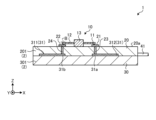
- FIG. 1 is a perspective view showing a heater according to an embodiment
- the heater 1 includes a bimetal switch 10, a first substrate 20, a second substrate 30, a heating resistor 31, and a pair of lead wires 40.
- the heater 1 is configured such that the energization state of the heating resistor 31 electrically connected to the pair of lead wires 40 can be switched by the bimetal switch 10 located on the first surface 1a which is the surface of the heater 1. is.
- Such a heater 1 is used for applications such as a hair iron, for example.
- FIG. 1 shows a three-dimensional orthogonal coordinate system including the Z-axis extending along the thickness direction of the heater 1 .
- Such an orthogonal coordinate system is also shown in other drawings used in the description below.
- FIG. 2 is an exploded perspective view showing an example of the heater according to the embodiment.
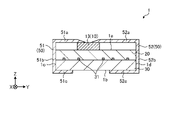
- FIG. 3 is a plan view showing the heater according to the embodiment. 4 is a cross-sectional view taken along the line AA shown in FIG. 3.
- FIG. 3 is a plan view showing the heater according to the embodiment. 4 is a cross-sectional view taken along the line AA shown in FIG. 3.
- the bimetal switch 10 has a fixed portion 13 and bimetal portions 11 and 12 .
- the fixed part 13 is fixed to the surface of the heater 1 .
- the fixing portion 13 can be made of heat-resistant material such as phenol resin, polyphenylene sulfide resin, or ceramic material such as alumina.
- the fixed portion 13 may be fixed to the first surface 1a of the heater 1 by, for example, a bonding material.
- the bimetal parts 11 and 12 are plate-like members, for example, and are laminates in which two types of metal materials having different coefficients of thermal expansion are superimposed.
- the laminate may have, for example, a high-expansion layer containing a small amount of Cr, Mn, Mg, etc. in an alloy of iron and nickel, and a low-expansion layer made of Invar.
- the bimetal parts 11 and 12 are deformed so that the contacts with the pads 21 and 22 described later are separated. As a result, the bimetal parts 11 and 12 cancel the energization of the heating resistor 31 through the lead wire 40 . Also, the bimetal parts 11 and 12 are deformed so as to come into contact with the pads 21 and 22, for example, when the temperature of the bimetal switch 10 drops below a predetermined temperature. As a result, the bimetal parts 11 and 12 restart the energization of the heating resistor 31 . That is, the bimetal parts 11 and 12 repeat contact and separation with the pads 21 and 22 in response to the temperature change of the heater 1 .
- the contact point is slightly displaced due to the difference in thermal expansion. Even so, the stress due to the difference in thermal expansion is difficult to concentrate. Therefore, even if the heater 1 is used for a long period of time, the contacts between the bimetal parts 11 and 12 and the pads 21 and 22 are unlikely to be broken, and the detection sensitivity is unlikely to be lowered.
- the first substrate 20 has a ceramic body 201 , pads 21 and 22 , vias 23 and 24 and recesses 25 .
- the ceramic body 201 is a flat member having a first surface 20a and a second surface 20b.
- the first surface 20a is located on the surface of the heater 1 and also serves as the first surface 1a (see FIG. 1).
- the second surface 20 b is located on the opposite side of the first surface 20 a and faces the second substrate 30 .
- the material of the ceramic body 201 is, for example, insulating ceramics.
- As the material of the ceramic body 201 for example, oxide ceramics, nitride ceramics, carbide ceramics, or the like can be used. Specifically, alumina ceramics, silicon nitride ceramics, aluminum nitride ceramics, silicon carbide ceramics, or the like can be used as the material of the ceramic body 201 .
- the pads 21 and 22 are located on the first surface 20a of the ceramic body 201.
- the pads 21 and 22 are positioned so as to overlap the vias 23 and 24 in plan view.
- Pads 21 and 22 are portions with which bimetal portions 11 and 12 of bimetal switch 10 are in contact.
- the spacing and size of the pads 21 and 22 are set according to the shape of the bimetal switch 10, for example.
- a metallic material such as tungsten can be used as tungsten.
- the vias 23 and 24 extend in the thickness direction of the first substrate 20 and are positioned so that one end thereof is exposed on the second surface 20b. The other ends of vias 23 and 24 are electrically connected to pads 21 and 22 .
- the vias 23,24 may have the same material as the pads 21,22, for example.
- Vias 23 and 24 may also contain, for example, molybdenum, copper, silver, nickel, or the like.
- the concave portion 25 is positioned so as to be in contact with the end surface 20c positioned at one end in the length direction of the ceramic body 201 .
- the recess 25 is open so as to penetrate the first surface 20 a and the second surface 20 b of the first substrate 20 .
- a lead wire 40 fixed with a bonding material is accommodated in the recess 25 .
- the second substrate 30 has a ceramic body 301, a heating resistor 31, terminals 31a and 31b, and a conductor 32.
- the ceramic body 301 is a flat member having a first surface 30a and a second surface 30b.
- the first surface 30 a faces the first substrate 20 .
- the second surface 20b is located on the opposite side of the first surface 30a and also serves as the second surface 1b of the heater 1 (see FIG. 8).
- the ceramic bodies 201 and 301 may be collectively referred to as the ceramic body 2 .
- the heating resistor 31 is positioned on the ceramic body 301 .
- the heating resistor 31 is a member that generates heat when current flows.
- the heat generating resistor 31 forms a heat generating region 35 on the other end side (X-axis negative direction side) of the heater 1 in the length direction.
- Heating resistor 31 may include a high resistance conductor including, for example, tungsten, molybdenum, and the like.
- the heating resistor 31 has a first resistor 311 and a second resistor 312 .
- the first resistor 311 has one end connected to the terminal 31 a and the other end connected to the first conductor 32 a of the conductor 32 .
- the second resistor 312 has one end connected to the terminal 31 b and the other end connected to the second conductor 32 b of the conductor 32 .
- the shapes of the first resistor 311 and the second resistor 312 are not limited to those shown in the drawings, and can be changed as appropriate according to the heat generation characteristics required of the heater 1, for example.
- the terminals 31a and 31b are positioned directly below the vias 23 and 24 and are electrically connected to the vias 23 and 24.
- the material of the terminals 31a and 31b may be the same as that of the heating resistor 31, for example.
- the conductor 32 is electrically connected to the heating resistor 31.
- the conductor 32 has a first conductor 32a and a second conductor 32b.
- the first conductor 32a is connected to the first resistor 311 and connected to the first lead 41 of the lead wire 40 via a bonding material.
- the second conductor 32b is connected to the second resistor 312 and is connected to the second lead 42 of the lead wire 40 via a bonding material.
- the conductor 32 is positioned so as to overlap the recess 25 in plan view.
- the conductor 32 may be, for example, a metal material containing tungsten, molybdenum, or the like, or plated with a metal material such as nickel.
- the material of the conductor 32 may be the same as that of the heating resistor 31, or may be different.
- As a bonding material for bonding the conductor 32 and the lead wire 40 for example, solder or brazing material such as silver solder can be used.
- the lead wire 40 is, for example, a wire containing a metal material such as nickel, iron, or a nickel-based heat-resistant alloy.
- the lead wire 40 is drawn out of the heater 1 from the recess 25 .
- the cross section of the lead wire 40 may be circular, elliptical, or rectangular, for example.
- the outer diameter of the lead wire 40 may be, for example, 0.5-2.0 mm.
- the lead wire 40 has a first lead 41 and a second lead 42 .
- the first lead 41 is connected to the first resistor 311 .
- the second lead 42 is connected to the second resistor 312 .
- the first lead 41 and the second lead 42 are electrically connected to an external power supply.
- FIG. FIG. 5 is an enlarged view of area B shown in FIG.
- pads 21 and 22 may be located directly above vias 23 and 24, respectively. Since the vias 23 and 24 have higher thermal conductivity than the ceramic body 2, the excessive temperature rise inside the heater 1 is likely to be reflected. If the pads 21 and 22, which are the contacts of the bimetal switch 10, are positioned directly above the vias 23 and 24, for example, responsiveness to excessive temperature rise is enhanced.
- the pads 21 and 22 may protrude from the first surface 20a toward the bimetal parts 11 and 12 of the bimetal switch 10, respectively. As a result, even if the ceramic body 2 is deformed due to thermal expansion, the pads 21 and 22 are positioned higher than the first surface 20a, thereby ensuring conduction except when an excessive temperature rise is detected. easier.
- the bimetal portion 12 of the bimetal switch 10 may have a contact portion 12a projecting toward the pad 22.
- the pad 22 may have a concave receiving portion 22a for receiving the contact portion 12a.
- FIG. 6 is a cross-sectional view showing another example of the heater according to the embodiment.
- the pad 22 may have a first layer 221 located on the first surface 20a (see FIG. 4) and a second layer 222 located on the first layer 221. good.
- the hardness of the second layer 222 may be lower than that of the first layer 221 .
- the second layer 222 may have a recessed receiving portion 22a for receiving the contact portion 12a.
- the material of the first layer 221 may be tungsten, for example.
- the material of the second layer 222 may be nickel, tin-nickel alloy, gold-nickel alloy, for example.
- the pad 22 may be laminated with three or more layers.
- the bimetal portion 12 and the pad 22 of the bimetal switch 10 have been described as an example, but the bimetal portion 11 and the pad 21 may be configured in the same manner.
- the heater 1 may further include a holding member 50.
- the clamping member 50 has clamping pieces 51 and 52 .
- the clamping piece 51 has a first portion 51a, a second portion 51b, and a third portion 51c.
- the first portion 51a is in contact with the fixing portion 13 of the bimetal switch 10 so as to press it toward the first substrate 20 side.
- the third portion 51 c is in contact with the second substrate 30 so as to press the second surface 1 b of the heater 1 .
- the second portion 51b is positioned between the first portion 51a and the third portion 51c and faces the side surface 1c of the heater 1 .
- the second portion 51b may be in contact with or separated from the side surface 1c.
- the clamping piece 52 has a first portion 52a, a second portion 52b, and a third portion 52c.
- the first portion 52a is in contact with the fixing portion 13 so as to press it toward the first substrate 20 side.
- the third portion 52c is in contact with the second substrate 30 so as to press the second surface 1b of the heater 1.
- the second portion 52b is positioned between the first portion 52a and the third portion 52c and faces the side surface 1d of the heater 1. As shown in FIG.
- the second portion 52b may be in contact with or separated from the side surface 1d.
- the material of the holding member 50 may be stainless steel, for example.
- the holding member 50 may fix the bimetal switch 10 by, for example, holding the bimetal switch 10 and the ceramic body 2 together.
- the bimetal switch 10 and the ceramic body 2 are integrally sandwiched, the bimetal switch 10 can be easily fixed directly to the first surface 1a of the ceramic body 2 without using a bonding material. This makes it difficult for heat to dissipate via the bonding material, making it easier to detect an excessive temperature rise.
- the holding member 50 may be fixed to the first surface 1a via a bonding material, for example.
- FIG. 9 is a perspective view showing another example of the heater according to the embodiment. 10 is a cross-sectional view of the heater shown in FIG. 9.
- FIG. 9 and 10 the holding member 50 shown in FIG. 8 may be configured to cover the first substrate 20 and the second substrate 30 entirely.
- the holding member 50 may have a first portion 50a, a second portion 50b, a third portion 50c, a fourth portion 50d, and a fifth portion 50e.
- the first portion 50a and the fifth portion 50e located at both ends of the clamping member 50 press the fixing portion 13 of the bimetal switch 10 toward the first substrate 20 side.
- the third portion 50 c is in contact with the second substrate 30 so as to press the second surface 1 b of the heater 1 .
- the second portion 50b is positioned between the first portion 50a and the third portion 50c and faces the side surface 1c of the heater 1.
- the fourth portion 50d is positioned between the third portion 50c and the fifth portion 50e and faces the side surface 1d of the heater 1.
- the second portion 50b and the fourth portion 50d may be in contact with or separated from the side surfaces 1c and 1d, respectively.
- the holding member 50 shown in FIGS. 9 and 10 may function as a case that accommodates the ceramic body 2 and the bimetal switch 10. As a result, even if the contact points between the bimetal switch 10 and the pads 21 and 22 are displaced due to differences in thermal expansion at various parts in the heater 1, stress is not applied to the bimetal switch 10, and durability is improved. do. Further, since the bimetal switch 10 detects an excessive temperature rise inside the clamping member 50 as a case, for example, detection accuracy is improved.
- FIG. 11 is a cross-sectional view showing another example of the heater according to the embodiment. As shown in FIG. 11, a pressing member 60 positioned above the bimetal switch 10 shown in FIG. 10 may be further provided.
- the material of the pressing member 60 may be, for example, a heat-resistant material, such as a resin such as phenol resin or polyphenylene sulfide resin. Also, the material of the pressing member 60 may be a ceramic material such as alumina. The material of the pressing member 60 may also be a metal material such as nickel, iron, or a nickel-based heat-resistant alloy.
- the clamping member 50 may, for example, indirectly press the bimetal switch 10 via the pressing member 60 without contacting it. This improves the durability of the bimetal switch 10 .
- FIG. 12 is a perspective view showing another example of the heater according to the embodiment.
- 13 is a sectional view of the heater shown in FIG. 12.
- the pressing member 60 that presses the bimetal switch 10 may have a width in the Y-axis direction larger than that of the fixed portion 13 .
- the pressing member 60 may have a first region 61 that contacts the fixed portion 13 of the bimetal switch 10 and a second region 62 that does not contact the fixed portion 13 .
- the first portion 50 a and the fifth portion 50 e of the holding member 50 may be positioned so as to contact the second region 62 of the pressing member 60 .
- the pressing member 60 can be flexed like a spring to fix the bimetal switch 10 . Therefore, the durability of the bimetal switch 10 is improved.
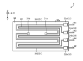
- FIG. 14 is a plan view showing another example of the heater according to the embodiment. 14, the illustration of the bimetal switch 10 and the first substrate 20 is omitted.
- the heater 1 may further include a temperature measuring resistor 33 and a conductor 34.
- the temperature measuring resistor 33 is located on the first surface 30a of the second substrate 30.
- the temperature measuring resistor 33 is arranged side by side with the first resistor 311 and the second resistor 312 .
- the resistance temperature detector 33 is connected to lead wires 43 and 44 via a conductor 34 .
- the conductor 34 has a first conductor 34a and a second conductor 34b.
- the first conductor 34a and the second conductor 34b are positioned with a predetermined gap between the first conductor 32a and the second conductor 32b.
- the temperature measuring resistor 33 has one end connected to the first conductor 34a and the other end connected to the second conductor 34b.
- the first conductor 34 a is connected to the lead wire 43 and the second conductor 34 b is connected to the lead wire 44 .
- the temperature measuring resistor 33 may be a temperature sensor for controlling the internal temperature of the heater 1, for example.
- the material of the temperature sensing resistor 33 may be, for example, a high-resistance conductor containing tungsten, molybdenum, or platinum.
- the temperature sensing resistor 33 can detect the temperature of the entire heater 1 and control the temperature of the heater 1 . For example, by detecting excessive temperature rise with the bimetal switch 10 while performing temperature control with the temperature measuring resistor 33, user convenience is improved.
- FIG. 15 is a plan view showing another example of the heater according to the embodiment. As shown in FIG. 15, a resistance temperature detector 33 may be positioned in a terminal-to-terminal region 31c between terminals 31a and 31b of the heater 1 shown in FIG.
- the temperature measuring resistor 33 may have an inter-terminal portion 33a positioned in the inter-terminal region 31c.
- the inter-terminal portion 33a may be repeatedly bent so as to extend along the second direction along the Y-axis direction intersecting the X-axis with respect to the first direction along the X-axis.
- the temperature sensing resistor 33 may have a cross-sectional area of the inter-terminal portion 33a smaller than the cross-sectional area of the portion other than the inter-terminal portion 33a. As a result, the accuracy of detection by the resistance temperature detector 33 is improved immediately below the bimetal switch 10 .
- the heater 1 includes the ceramic body 2, the heating resistor 31, and the bimetal switch 10.
- the ceramic body 2 has a first side 1a and a second side 1b opposite the first side 1a.
- the heating resistor 31 is positioned inside the ceramic body 2 and has a first resistor 311 and a second resistor 322 .
- the bimetal switch 10 is positioned between the first resistor 311 and the second resistor 312 and switches the energization state to the heating resistor 31 . Thereby, user convenience can be improved.
- the hair iron according to the embodiment includes the heater 1 described above.
- the heater 1 is less likely to overheat and can be stably used for a long period of time, so that, for example, it is possible to provide an excellent curling iron that does not damage the hair.
Abstract
This heater comprises a ceramic body, a heat generation resistor, and a bimetal switch. The ceramic body has: a first surface; and a second surface located opposite to the first surface. The heat generation resistor is located inside the ceramic body, and has a first resistor and a second resistor. The bimetal switch is located between the first resistor and the second resistor.
Description
開示の実施形態は、ヒータおよびヘアアイロンに関する。
The disclosed embodiments relate to heaters and curling irons.
従来、セラミック体の内部に発熱抵抗体を有するヒータが知られている。このようなヒータは、例えばヘアアイロンなどの電熱器具に利用される。
A heater having a heating resistor inside a ceramic body is conventionally known. Such heaters are used, for example, in electric heating appliances such as hair irons.
実施形態の一態様に係るヒータは、セラミック体と、発熱抵抗体と、バイメタルスイッチとを備える。セラミック体は、第1面および前記第1面の反対に位置する第2面を有している。発熱抵抗体は、前記セラミック体の内部に位置し、第1抵抗体および第2抵抗体を有している。バイメタルスイッチは、前記第1抵抗体と前記第2抵抗体との間に位置している。
A heater according to one aspect of an embodiment includes a ceramic body, a heating resistor, and a bimetal switch. The ceramic body has a first side and a second side opposite the first side. The heating resistor is located inside the ceramic body and has a first resistor and a second resistor. A bimetal switch is positioned between the first resistor and the second resistor.
かかるヒータは、例えば、異常昇温時に通電を遮断させるヒューズとともに用いられる場合がある。しかしながら、通電を遮断したヒューズは再利用できず、交換する必要があることから、ユーザの利便性向上が望まれている。
Such a heater may be used, for example, with a fuse that cuts off current when the temperature rises abnormally. However, since a fuse that has been de-energized cannot be reused and needs to be replaced, it is desired to improve user convenience.
さらには、ヒータ表面にヒューズを接触するように搭載した場合において、ヒータとの接触が悪い場合には、温度が低めに検知されてヒータが過昇温するおそれがあった。また、精度よく接触させた場合でも、ヒータが急速に昇温した場合、ヒータ周囲の熱引きが悪い場合、ヒータが局所的に加熱した場合などにヒューズの検知速度がヒータの昇温速度に追随できずにヒューズが温度を低めに検知することで、ヒータが過昇温するおそれがあった。
Furthermore, when the fuse is mounted in contact with the surface of the heater, if the contact with the heater is poor, the temperature may be detected as low and the heater may overheat. In addition, even when contact is made with good precision, the fuse detection speed follows the heater temperature rise speed when the heater temperature rises rapidly, when the heat transfer around the heater is poor, when the heater heats up locally, etc. There was a risk that the heater would overheat due to the fuse detecting the temperature at a low level.
そこで、ユーザの利便性を向上することができるヒータおよびヘアアイロンの提供が期待されている。
Therefore, the provision of heaters and curling irons that can improve user convenience is expected.
以下、添付図面を参照して、本願の開示するヒータおよびヘアアイロンの実施形態について説明する。なお、以下に示す実施形態により本開示が限定されるものではない。また、図面は模式的なものであり、各要素の寸法の関係、各要素の比率などは、現実と異なる場合があることに留意する必要がある。
Hereinafter, embodiments of a heater and a hair iron disclosed in the present application will be described with reference to the accompanying drawings. It should be noted that the present disclosure is not limited by the embodiments shown below. Also, it should be noted that the drawings are schematic, and the relationship of dimensions of each element, the ratio of each element, and the like may differ from reality.
<実施形態>
最初に、実施形態に係るヒータについて、図1~図5を参照しながら説明する。図1は、実施形態に係るヒータを示す斜視図である。 <Embodiment>
First, a heater according to an embodiment will be described with reference to FIGS. 1 to 5. FIG. 1 is a perspective view showing a heater according to an embodiment; FIG.
最初に、実施形態に係るヒータについて、図1~図5を参照しながら説明する。図1は、実施形態に係るヒータを示す斜視図である。 <Embodiment>
First, a heater according to an embodiment will be described with reference to FIGS. 1 to 5. FIG. 1 is a perspective view showing a heater according to an embodiment; FIG.
図1に示すように、実施形態に係るヒータ1は、バイメタルスイッチ10と、第1基板20と、第2基板30と、発熱抵抗体31と、一対のリード線40とを備える。ヒータ1は、一対のリード線40と電気的に接続された発熱抵抗体31への通電状態を、ヒータ1の表面である第1面1aに位置するバイメタルスイッチ10によって切り替え可能に構成されたものである。かかるヒータ1は、例えば、ヘアアイロンなどの用途に用いられる。
As shown in FIG. 1, the heater 1 according to the embodiment includes a bimetal switch 10, a first substrate 20, a second substrate 30, a heating resistor 31, and a pair of lead wires 40. The heater 1 is configured such that the energization state of the heating resistor 31 electrically connected to the pair of lead wires 40 can be switched by the bimetal switch 10 located on the first surface 1a which is the surface of the heater 1. is. Such a heater 1 is used for applications such as a hair iron, for example.
なお、説明を分かりやすくするために、図1には、ヒータ1の厚み方向に沿って延びるZ軸を含む3次元の直交座標系を図示している。かかる直交座標系は、後出の説明に用いる他の図面でも示している。
In order to make the explanation easier to understand, FIG. 1 shows a three-dimensional orthogonal coordinate system including the Z-axis extending along the thickness direction of the heater 1 . Such an orthogonal coordinate system is also shown in other drawings used in the description below.
図2は、実施形態に係るヒータの一例を示す分解斜視図である。図3は、実施形態に係るヒータを示す平面図である。図4は、図3に示すA-A線の断面図である。
FIG. 2 is an exploded perspective view showing an example of the heater according to the embodiment. FIG. 3 is a plan view showing the heater according to the embodiment. 4 is a cross-sectional view taken along the line AA shown in FIG. 3. FIG.
バイメタルスイッチ10は、固定部13と、バイメタル部11,12とを有する。固定部13は、ヒータ1の表面に固定される。固定部13は、耐熱性を有する材料、例えば、フェノール樹脂、ポリフェニレンサルファイド樹脂またはアルミナ等のセラミック材料などを使用できる。固定部13は、例えば接合材によりヒータ1の第1面1aに固定されてもよい。
The bimetal switch 10 has a fixed portion 13 and bimetal portions 11 and 12 . The fixed part 13 is fixed to the surface of the heater 1 . The fixing portion 13 can be made of heat-resistant material such as phenol resin, polyphenylene sulfide resin, or ceramic material such as alumina. The fixed portion 13 may be fixed to the first surface 1a of the heater 1 by, for example, a bonding material.
バイメタル部11,12は、例えば、板状部材であり、熱膨張率の異なる二種類の金属材料を重ね合わせた積層体である。積層体は、例えば、鉄とニッケルの合金に、少量のCr、Mn、Mgなどを含む高膨張層と、インバーからなる低膨張層とを有してもよい。
The bimetal parts 11 and 12 are plate-like members, for example, and are laminates in which two types of metal materials having different coefficients of thermal expansion are superimposed. The laminate may have, for example, a high-expansion layer containing a small amount of Cr, Mn, Mg, etc. in an alloy of iron and nickel, and a low-expansion layer made of Invar.
バイメタル部11,12は、例えば、バイメタルスイッチ10が所定温度以上になると、後述するパッド21,22との接点が離れるように変形する。これにより、バイメタル部11,12は、リード線40を介した発熱抵抗体31への通電を解除させる。また、バイメタル部11,12は、例えば、バイメタルスイッチ10が所定温度以下になると、パッド21,22と接触するように変形する。これにより、バイメタル部11,12は、発熱抵抗体31への通電を再開させる。すなわち、バイメタル部11,12は、ヒータ1の温度変化に応答し、パッド21,22との接離を繰り返す。
For example, when the temperature of the bimetal switch 10 reaches or exceeds a predetermined temperature, the bimetal parts 11 and 12 are deformed so that the contacts with the pads 21 and 22 described later are separated. As a result, the bimetal parts 11 and 12 cancel the energization of the heating resistor 31 through the lead wire 40 . Also, the bimetal parts 11 and 12 are deformed so as to come into contact with the pads 21 and 22, for example, when the temperature of the bimetal switch 10 drops below a predetermined temperature. As a result, the bimetal parts 11 and 12 restart the energization of the heating resistor 31 . That is, the bimetal parts 11 and 12 repeat contact and separation with the pads 21 and 22 in response to the temperature change of the heater 1 .
例えば、バイメタル部11,12とパッド21,22とが接触して導通している状態において、ヒータ1が温度上昇に伴って熱膨張した場合には、熱膨張差でわずかに接点がずれた場合であっても、熱膨張差による応力は集中しにくい。そのため、ヒータ1を長期間使用してもバイメタル部11,12とパッド21,22との接点は壊れにくく、検知感度が低下しにくい。
For example, when the heater 1 thermally expands due to a rise in temperature in a state where the bimetal parts 11 and 12 and the pads 21 and 22 are in contact with each other and are electrically connected to each other, the contact point is slightly displaced due to the difference in thermal expansion. Even so, the stress due to the difference in thermal expansion is difficult to concentrate. Therefore, even if the heater 1 is used for a long period of time, the contacts between the bimetal parts 11 and 12 and the pads 21 and 22 are unlikely to be broken, and the detection sensitivity is unlikely to be lowered.
第1基板20は、セラミック体201と、パッド21,22と、ビア23,24と、凹部25とを有する。セラミック体201は、第1面20aおよび第2面20bを有する平板状の部材である。第1面20aは、ヒータ1の表面に位置しており、第1面1a(図1参照)を兼ねている。第2面20bは、第1面20aとは反対側に位置し、第2基板30と向かい合っている。
The first substrate 20 has a ceramic body 201 , pads 21 and 22 , vias 23 and 24 and recesses 25 . The ceramic body 201 is a flat member having a first surface 20a and a second surface 20b. The first surface 20a is located on the surface of the heater 1 and also serves as the first surface 1a (see FIG. 1). The second surface 20 b is located on the opposite side of the first surface 20 a and faces the second substrate 30 .
セラミック体201の材料は、例えば、絶縁性を有するセラミックスである。セラミック体201の材料としては、例えば、酸化物セラミックス、窒化物セラミックスまたは炭化物セラミックス等を使用することができる。具体的には、アルミナ質セラミックス、窒化珪素質セラミックス、窒化アルミニウム質セラミックス、炭化珪素質セラミックス等をセラミック体201の材料として用いることができる。
The material of the ceramic body 201 is, for example, insulating ceramics. As the material of the ceramic body 201, for example, oxide ceramics, nitride ceramics, carbide ceramics, or the like can be used. Specifically, alumina ceramics, silicon nitride ceramics, aluminum nitride ceramics, silicon carbide ceramics, or the like can be used as the material of the ceramic body 201 .
パッド21,22は、セラミック体201の第1面20a上に位置している。パッド21,22は、平面視でビア23,24と重なるように位置している。パッド21,22は、バイメタルスイッチ10のバイメタル部11,12が接する部分である。パッド21,22の間隔およびサイズは、例えば、バイメタルスイッチ10の形状等に応じて設定される。パッド21,22の材料としては、例えば、タングステンなどの金属材料を使用することができる。
The pads 21 and 22 are located on the first surface 20a of the ceramic body 201. The pads 21 and 22 are positioned so as to overlap the vias 23 and 24 in plan view. Pads 21 and 22 are portions with which bimetal portions 11 and 12 of bimetal switch 10 are in contact. The spacing and size of the pads 21 and 22 are set according to the shape of the bimetal switch 10, for example. As a material for the pads 21 and 22, for example, a metallic material such as tungsten can be used.
ビア23,24は、第1基板20の厚み方向に延び、一端が第2面20bに露出するように位置している。ビア23,24の他端は、パッド21,22と電気的に接続されている。
The vias 23 and 24 extend in the thickness direction of the first substrate 20 and are positioned so that one end thereof is exposed on the second surface 20b. The other ends of vias 23 and 24 are electrically connected to pads 21 and 22 .
ビア23,24は、例えば、パッド21,22と同じ材料を有してもよい。また、ビア23,24は、例えば、モリブデン、銅、銀、ニッケルなどを含有してもよい。
The vias 23,24 may have the same material as the pads 21,22, for example. Vias 23 and 24 may also contain, for example, molybdenum, copper, silver, nickel, or the like.
凹部25は、セラミック体201の長さ方向の一端に位置する端面20cに接するように位置している。凹部25は、第1基板20の第1面20aおよび第2面20bを貫通するように開口している。凹部25には、接合材で固定されたリード線40が収容される。
The concave portion 25 is positioned so as to be in contact with the end surface 20c positioned at one end in the length direction of the ceramic body 201 . The recess 25 is open so as to penetrate the first surface 20 a and the second surface 20 b of the first substrate 20 . A lead wire 40 fixed with a bonding material is accommodated in the recess 25 .
第2基板30は、セラミック体301と、発熱抵抗体31と、端子31a,31bと、導体32とを有する。セラミック体301は、第1面30aおよび第2面30bを有する平板状の部材である。第1面30aは、第1基板20と向かい合っている。第2面20bは、第1面30aとは反対側に位置し、ヒータ1の第2面1b(図8参照)を兼ねている。以下、セラミック体201,301を総称して、セラミック体2と称する場合がある。
The second substrate 30 has a ceramic body 301, a heating resistor 31, terminals 31a and 31b, and a conductor 32. The ceramic body 301 is a flat member having a first surface 30a and a second surface 30b. The first surface 30 a faces the first substrate 20 . The second surface 20b is located on the opposite side of the first surface 30a and also serves as the second surface 1b of the heater 1 (see FIG. 8). Hereinafter, the ceramic bodies 201 and 301 may be collectively referred to as the ceramic body 2 .
発熱抵抗体31は、セラミック体301の上に位置している。発熱抵抗体31は、電流が流れることによって発熱する部材である。発熱抵抗体31は、ヒータ1の長さ方向の他端側(X軸負方向側)に発熱領域35を形成する。発熱抵抗体31は、例えば、タングステン、モリブデンなどを含む高抵抗の導体を含んでよい。
The heating resistor 31 is positioned on the ceramic body 301 . The heating resistor 31 is a member that generates heat when current flows. The heat generating resistor 31 forms a heat generating region 35 on the other end side (X-axis negative direction side) of the heater 1 in the length direction. Heating resistor 31 may include a high resistance conductor including, for example, tungsten, molybdenum, and the like.
発熱抵抗体31は、第1抵抗体311と第2抵抗体312とを有する。第1抵抗体311は、一端が端子31aに接続され、他端が導体32の第1導体32aに接続されている。第2抵抗体312は、一端が端子31bに接続され、他端が導体32の第2導体32bに接続されている。なお、第1抵抗体311および第2抵抗体312の形状は、図示したものに限られず、例えば、ヒータ1に要求される発熱特性に応じて適宜変更することができる。
The heating resistor 31 has a first resistor 311 and a second resistor 312 . The first resistor 311 has one end connected to the terminal 31 a and the other end connected to the first conductor 32 a of the conductor 32 . The second resistor 312 has one end connected to the terminal 31 b and the other end connected to the second conductor 32 b of the conductor 32 . The shapes of the first resistor 311 and the second resistor 312 are not limited to those shown in the drawings, and can be changed as appropriate according to the heat generation characteristics required of the heater 1, for example.
端子31a,31bは、ビア23,24の直下に位置しており、ビア23,24と電気的に接続されている。端子31a,31bの材料は、例えば、発熱抵抗体31と同じであってもよい。
The terminals 31a and 31b are positioned directly below the vias 23 and 24 and are electrically connected to the vias 23 and 24. The material of the terminals 31a and 31b may be the same as that of the heating resistor 31, for example.
導体32は、発熱抵抗体31と電気的に接続されている。導体32は、第1導体32aと第2導体32bとを有する。第1導体32aは、第1抵抗体311に接続され、接合材を介してリード線40の第1リード41に接続されている。第2導体32bは、第2抵抗体312に接続され、接合材を介してリード線40の第2リード42に接続されている。導体32は、平面視で凹部25と重なるように位置している。導体32は、例えば、タングステン、モリブデンなどを含む金属材料、さらにニッケルなどの金属材料をメッキしたものであってよい。導体32の材料は、発熱抵抗体31と同じであってもよく、異なってもよい。なお、導体32とリード線40とを接合する接合材としては、例えば、はんだまたは銀ろう等のろう材を用いることができる。
The conductor 32 is electrically connected to the heating resistor 31. The conductor 32 has a first conductor 32a and a second conductor 32b. The first conductor 32a is connected to the first resistor 311 and connected to the first lead 41 of the lead wire 40 via a bonding material. The second conductor 32b is connected to the second resistor 312 and is connected to the second lead 42 of the lead wire 40 via a bonding material. The conductor 32 is positioned so as to overlap the recess 25 in plan view. The conductor 32 may be, for example, a metal material containing tungsten, molybdenum, or the like, or plated with a metal material such as nickel. The material of the conductor 32 may be the same as that of the heating resistor 31, or may be different. As a bonding material for bonding the conductor 32 and the lead wire 40, for example, solder or brazing material such as silver solder can be used.
リード線40は、例えば、ニッケル、鉄またはニッケル系耐熱合金等の金属材料を含む線材である。リード線40は、凹部25からヒータ1の外部に引き出されている。リード線40の断面は、例えば円形状であってもよく、楕円形状、矩形状であってもよい。リード線40の外径は、例えば0.5~2.0mmであってもよい。
The lead wire 40 is, for example, a wire containing a metal material such as nickel, iron, or a nickel-based heat-resistant alloy. The lead wire 40 is drawn out of the heater 1 from the recess 25 . The cross section of the lead wire 40 may be circular, elliptical, or rectangular, for example. The outer diameter of the lead wire 40 may be, for example, 0.5-2.0 mm.
リード線40は、第1リード41と第2リード42とを有する。第1リード41は、第1抵抗体311に接続されている。第2リード42は、第2抵抗体312に接続されている。第1リード41および第2リード42は、外部電源に電気的に接続される。
The lead wire 40 has a first lead 41 and a second lead 42 . The first lead 41 is connected to the first resistor 311 . The second lead 42 is connected to the second resistor 312 . The first lead 41 and the second lead 42 are electrically connected to an external power supply.
次に、図4~図5を用いて、実施形態に係るヒータ1についてさらに説明する。図5は、図4に示す領域Bの拡大図である。
Next, the heater 1 according to the embodiment will be further described with reference to FIGS. 4 and 5. FIG. FIG. 5 is an enlarged view of area B shown in FIG.
図4に示すように、パッド21,22は、ビア23,24の直上にそれぞれ位置していてもよい。ビア23,24は、セラミック体2よりも熱伝導性が高いことから、ヒータ1内部の過昇温が反映されやすい。かかるビア23,24の直上にバイメタルスイッチ10の接点であるパッド21,22が位置していると、例えば、過昇温に対する応答性が高くなる。
As shown in FIG. 4, pads 21 and 22 may be located directly above vias 23 and 24, respectively. Since the vias 23 and 24 have higher thermal conductivity than the ceramic body 2, the excessive temperature rise inside the heater 1 is likely to be reflected. If the pads 21 and 22, which are the contacts of the bimetal switch 10, are positioned directly above the vias 23 and 24, for example, responsiveness to excessive temperature rise is enhanced.
また、パッド21,22は、第1面20aからバイメタルスイッチ10のバイメタル部11,12側に向けてそれぞれ突出していてもよい。これにより、セラミック体2が熱膨張により変形した場合であっても、パッド21,22が第1面20aよりも高い位置にあることで、過昇温を検知した場合を除いて導通が確保しやすくなる。
Also, the pads 21 and 22 may protrude from the first surface 20a toward the bimetal parts 11 and 12 of the bimetal switch 10, respectively. As a result, even if the ceramic body 2 is deformed due to thermal expansion, the pads 21 and 22 are positioned higher than the first surface 20a, thereby ensuring conduction except when an excessive temperature rise is detected. easier.
また、図5に示すように、バイメタルスイッチ10のバイメタル部12は、パッド22に向かうように突出する接点部12aを有してもよい。また、パッド22は、接点部12aを受ける凹状の受け部22aを有してもよい。これにより、バイメタル部12とパッド22との接触面積が増大することから、例えばセラミック体2が熱膨張により変形した場合であっても、過昇温を検知した場合を除いて導通が確保しやすくなる。
Further, as shown in FIG. 5, the bimetal portion 12 of the bimetal switch 10 may have a contact portion 12a projecting toward the pad 22. Also, the pad 22 may have a concave receiving portion 22a for receiving the contact portion 12a. As a result, the contact area between the bimetal portion 12 and the pad 22 is increased, so even if the ceramic body 2 is deformed due to thermal expansion, for example, it is easy to ensure continuity except when an excessive temperature rise is detected. Become.
<別の実施形態>
図6は、実施形態に係るヒータの別の一例を示す断面図である。図6に示すように、パッド22は、第1面20a(図4参照)の上に位置する第1層221と、第1層221の上に位置する第2層222とを有してもよい。 <Another embodiment>
FIG. 6 is a cross-sectional view showing another example of the heater according to the embodiment. As shown in FIG. 6, thepad 22 may have a first layer 221 located on the first surface 20a (see FIG. 4) and a second layer 222 located on the first layer 221. good.
図6は、実施形態に係るヒータの別の一例を示す断面図である。図6に示すように、パッド22は、第1面20a(図4参照)の上に位置する第1層221と、第1層221の上に位置する第2層222とを有してもよい。 <Another embodiment>
FIG. 6 is a cross-sectional view showing another example of the heater according to the embodiment. As shown in FIG. 6, the
第2層222は、第1層221よりも硬度が小さくてもよい。第2層222は、接点部12aを受ける凹状の受け部22aを有してもよい。これにより、バイメタル部12がパッド22に圧接されることで接触面積の増大が期待できることから、例えばセラミック体2が熱膨張により変形した場合であっても、過昇温を検知した場合を除いて導通が確保しやすくなる。
The hardness of the second layer 222 may be lower than that of the first layer 221 . The second layer 222 may have a recessed receiving portion 22a for receiving the contact portion 12a. As a result, since the bimetal portion 12 is pressed against the pad 22, an increase in the contact area can be expected. It becomes easier to ensure continuity.
ここで、第1層221の材料は、例えば、タングステンであってもよい。また、第2層222の材料は、例えば、ニッケル、錫-ニッケル合金、金-ニッケル合金であってもよい。また、パッド22は、3層以上が積層されていてもよい。
Here, the material of the first layer 221 may be tungsten, for example. Also, the material of the second layer 222 may be nickel, tin-nickel alloy, gold-nickel alloy, for example. Moreover, the pad 22 may be laminated with three or more layers.
なお、図5、図6では、バイメタルスイッチ10のバイメタル部12とパッド22を例に挙げて説明したが、バイメタル部11とパッド21についても、同様に構成されてもよい。
5 and 6, the bimetal portion 12 and the pad 22 of the bimetal switch 10 have been described as an example, but the bimetal portion 11 and the pad 21 may be configured in the same manner.
図7は、実施形態に係るヒータの別の一例を示す斜視図である。図8は、図7に示すヒータの断面図である。
FIG. 7 is a perspective view showing another example of the heater according to the embodiment. 8 is a sectional view of the heater shown in FIG. 7. FIG.
図7および図8に示すように、ヒータ1は、挟持部材50をさらに備えてもよい。
As shown in FIGS. 7 and 8, the heater 1 may further include a holding member 50.
挟持部材50は、挟持部片51,52を有する。挟持部片51は、第1部分51aと、第2部分51bと、第3部分51cとを有する。第1部分51aは、バイメタルスイッチ10の固定部13を第1基板20側に押圧するように接している。第3部分51cは、ヒータ1の第2面1bを押圧するように第2基板30に接している。第2部分51bは、第1部分51aと第3部分51cとの間に位置しており、ヒータ1の側面1cと向かい合って位置している。第2部分51bは、側面1cと接していてもよく、離れていてもよい。
The clamping member 50 has clamping pieces 51 and 52 . The clamping piece 51 has a first portion 51a, a second portion 51b, and a third portion 51c. The first portion 51a is in contact with the fixing portion 13 of the bimetal switch 10 so as to press it toward the first substrate 20 side. The third portion 51 c is in contact with the second substrate 30 so as to press the second surface 1 b of the heater 1 . The second portion 51b is positioned between the first portion 51a and the third portion 51c and faces the side surface 1c of the heater 1 . The second portion 51b may be in contact with or separated from the side surface 1c.
挟持部片52は、第1部分52aと、第2部分52bと、第3部分52cとを有する。第1部分52aは、固定部13を第1基板20側に押圧するように接している。第3部分52cは、ヒータ1の第2面1bを押圧するように第2基板30に接している。第2部分52bは、第1部分52aと第3部分52cとの間に位置しており、ヒータ1の側面1dと向かい合って位置している。第2部分52bは、側面1dと接していてもよく、離れていてもよい。
The clamping piece 52 has a first portion 52a, a second portion 52b, and a third portion 52c. The first portion 52a is in contact with the fixing portion 13 so as to press it toward the first substrate 20 side. The third portion 52c is in contact with the second substrate 30 so as to press the second surface 1b of the heater 1. As shown in FIG. The second portion 52b is positioned between the first portion 52a and the third portion 52c and faces the side surface 1d of the heater 1. As shown in FIG. The second portion 52b may be in contact with or separated from the side surface 1d.
挟持部材50の材料は、例えば、ステンレス鋼であってもよい。挟持部材50は、例えば、バイメタルスイッチ10とセラミック体2とを一体に挟み込むことでバイメタルスイッチ10を固定してもよい。バイメタルスイッチ10とセラミック体2とを一体に挟み込むと、例えば接合材を介することなく、バイメタルスイッチ10をセラミック体2の第1面1aに直接固定しやすくなる。これにより、接合材を介した熱の散逸が生じにくくなることから、過昇温を検知しやすくなる。なお、挟持部材50は、例えば接合材を介して第1面1aに固定されてもよい。
The material of the holding member 50 may be stainless steel, for example. The holding member 50 may fix the bimetal switch 10 by, for example, holding the bimetal switch 10 and the ceramic body 2 together. When the bimetal switch 10 and the ceramic body 2 are integrally sandwiched, the bimetal switch 10 can be easily fixed directly to the first surface 1a of the ceramic body 2 without using a bonding material. This makes it difficult for heat to dissipate via the bonding material, making it easier to detect an excessive temperature rise. The holding member 50 may be fixed to the first surface 1a via a bonding material, for example.
図9は、実施形態に係るヒータの別の一例を示す斜視図である。図10は、図9に示すヒータの断面図である。図9および図10に示すように、図8に示す挟持部材50は、第1基板20および第2基板30の全体を覆うように構成されてもよい。
FIG. 9 is a perspective view showing another example of the heater according to the embodiment. 10 is a cross-sectional view of the heater shown in FIG. 9. FIG. As shown in FIGS. 9 and 10, the holding member 50 shown in FIG. 8 may be configured to cover the first substrate 20 and the second substrate 30 entirely.
挟持部材50は、第1部分50aと、第2部分50bと、第3部分50cと、第4部分50dと、第5部分50eとを有してもよい。挟持部材50の両端に位置する第1部分50aおよび第5部分50eはそれぞれ、バイメタルスイッチ10の固定部13を第1基板20側に押圧している。第3部分50cは、ヒータ1の第2面1bを押圧するように第2基板30に接している。第2部分50bは、第1部分50aと第3部分50cとの間に位置しており、ヒータ1の側面1cと向かい合って位置している。第4部分50dは、第3部分50cと第5部分50eとの間に位置しており、ヒータ1の側面1dと向かい合って位置している。第2部分50bおよび第4部分50dはそれぞれ、側面1c,1dと接していてもよく、離れていてもよい。
The holding member 50 may have a first portion 50a, a second portion 50b, a third portion 50c, a fourth portion 50d, and a fifth portion 50e. The first portion 50a and the fifth portion 50e located at both ends of the clamping member 50 press the fixing portion 13 of the bimetal switch 10 toward the first substrate 20 side. The third portion 50 c is in contact with the second substrate 30 so as to press the second surface 1 b of the heater 1 . The second portion 50b is positioned between the first portion 50a and the third portion 50c and faces the side surface 1c of the heater 1. As shown in FIG. The fourth portion 50d is positioned between the third portion 50c and the fifth portion 50e and faces the side surface 1d of the heater 1. As shown in FIG. The second portion 50b and the fourth portion 50d may be in contact with or separated from the side surfaces 1c and 1d, respectively.
図9および図10に示す挟持部材50は、セラミック体2およびバイメタルスイッチ10を収容するケースとして機能してもよい。これにより、例えば、ヒータ1内の各部位における熱膨張差によってバイメタルスイッチ10とパッド21,22との接点がずれた場合であっても、バイメタルスイッチ10には応力がかからないため、耐久性が向上する。また、バイメタルスイッチ10は、ケースとしての挟持部材50の内部における過昇温の検知になることから、例えば、検知精度が向上する。
The holding member 50 shown in FIGS. 9 and 10 may function as a case that accommodates the ceramic body 2 and the bimetal switch 10. As a result, even if the contact points between the bimetal switch 10 and the pads 21 and 22 are displaced due to differences in thermal expansion at various parts in the heater 1, stress is not applied to the bimetal switch 10, and durability is improved. do. Further, since the bimetal switch 10 detects an excessive temperature rise inside the clamping member 50 as a case, for example, detection accuracy is improved.
図11は、実施形態に係るヒータの別の一例を示す断面図である。図11に示すように、図10に示すバイメタルスイッチ10の上に位置する押圧部材60をさらに備えてもよい。
FIG. 11 is a cross-sectional view showing another example of the heater according to the embodiment. As shown in FIG. 11, a pressing member 60 positioned above the bimetal switch 10 shown in FIG. 10 may be further provided.
押圧部材60の材料は、例えば、耐熱性を有する材料であってもよく、例えば、フェノール樹脂、ポリフェニレンサルファイド樹脂などの樹脂であってもよい。また、押圧部材60の材料は、アルミナ等のセラミック材料であってもよい。押圧部材60の材料は、さらにはニッケル、鉄またはニッケル系耐熱合金等の金属材料などであってもよい。挟持部材50は、例えば、バイメタルスイッチ10には接触せず、押圧部材60を介して間接的に押圧してもよい。これにより、バイメタルスイッチ10の耐久性が向上する。
The material of the pressing member 60 may be, for example, a heat-resistant material, such as a resin such as phenol resin or polyphenylene sulfide resin. Also, the material of the pressing member 60 may be a ceramic material such as alumina. The material of the pressing member 60 may also be a metal material such as nickel, iron, or a nickel-based heat-resistant alloy. The clamping member 50 may, for example, indirectly press the bimetal switch 10 via the pressing member 60 without contacting it. This improves the durability of the bimetal switch 10 .
図12は、実施形態に係るヒータの別の一例を示す斜視図である。図13は、図12に示すヒータの断面図である。図12および図13に示すようにバイメタルスイッチ10を押圧する押圧部材60は、Y軸方向の幅が固定部13よりも大きくてもよい。
FIG. 12 is a perspective view showing another example of the heater according to the embodiment. 13 is a sectional view of the heater shown in FIG. 12. FIG. As shown in FIGS. 12 and 13 , the pressing member 60 that presses the bimetal switch 10 may have a width in the Y-axis direction larger than that of the fixed portion 13 .
押圧部材60は、バイメタルスイッチ10の固定部13に接する第1領域61と、固定部13に接していない第2領域62とを有してもよい。挟持部材50の第1部分50aおよび第5部分50eは、押圧部材60のうち、第2領域62に接するように位置してもよい。これにより、例えばセラミック体2が熱膨張により変形した場合であっても、押圧部材60がばねのようにたわみながらバイメタルスイッチ10を固定することができる。このため、バイメタルスイッチ10の耐久性が向上する。
The pressing member 60 may have a first region 61 that contacts the fixed portion 13 of the bimetal switch 10 and a second region 62 that does not contact the fixed portion 13 . The first portion 50 a and the fifth portion 50 e of the holding member 50 may be positioned so as to contact the second region 62 of the pressing member 60 . As a result, even if the ceramic body 2 is deformed due to thermal expansion, the pressing member 60 can be flexed like a spring to fix the bimetal switch 10 . Therefore, the durability of the bimetal switch 10 is improved.
図14は、実施形態に係るヒータの別の一例を示す平面図である。なお、図14では、バイメタルスイッチ10および第1基板20の図示を省略している。
FIG. 14 is a plan view showing another example of the heater according to the embodiment. 14, the illustration of the bimetal switch 10 and the first substrate 20 is omitted.
図14に示すように、ヒータ1は、測温抵抗体33と導体34とをさらに備えてもよい。
As shown in FIG. 14, the heater 1 may further include a temperature measuring resistor 33 and a conductor 34.
測温抵抗体33は、第2基板30の第1面30a上に位置している。測温抵抗体33は、第1抵抗体311および第2抵抗体312と並ぶように配列されている。測温抵抗体33は、導体34を介してリード線43,44に接続されている。
The temperature measuring resistor 33 is located on the first surface 30a of the second substrate 30. The temperature measuring resistor 33 is arranged side by side with the first resistor 311 and the second resistor 312 . The resistance temperature detector 33 is connected to lead wires 43 and 44 via a conductor 34 .
導体34は、第1導体34aと第2導体34bとを有している。第1導体34aおよび第2導体34bは、第1導体32aと第2導体32bとの間に、所定の間隔を設けて位置している。測温抵抗体33は、一端が第1導体34aに接続され、他端が第2導体34bに接続されている。第1導体34aは、リード線43に接続され、第2導体34bは、リード線44に接続されている。
The conductor 34 has a first conductor 34a and a second conductor 34b. The first conductor 34a and the second conductor 34b are positioned with a predetermined gap between the first conductor 32a and the second conductor 32b. The temperature measuring resistor 33 has one end connected to the first conductor 34a and the other end connected to the second conductor 34b. The first conductor 34 a is connected to the lead wire 43 and the second conductor 34 b is connected to the lead wire 44 .
測温抵抗体33は、例えば、ヒータ1の内部温度を制御するための温度センサであってもよい。測温抵抗体33の材料は、例えば、タングステン、モリブデンなどを含む高抵抗の導体や、白金であってもよい。測温抵抗体33は、ヒータ1全体の温度を検知して、ヒータ1の温度制御を行うことができる。例えば、測温抵抗体33で温度制御を行いつつ、バイメタルスイッチ10で過昇温を検知することにより、ユーザの利便性が向上する。
The temperature measuring resistor 33 may be a temperature sensor for controlling the internal temperature of the heater 1, for example. The material of the temperature sensing resistor 33 may be, for example, a high-resistance conductor containing tungsten, molybdenum, or platinum. The temperature sensing resistor 33 can detect the temperature of the entire heater 1 and control the temperature of the heater 1 . For example, by detecting excessive temperature rise with the bimetal switch 10 while performing temperature control with the temperature measuring resistor 33, user convenience is improved.
図15は、実施形態に係るヒータの別の一例を示す平面図である。図15に示すように、図14に示すヒータ1が有する端子31a,31bの間の端子間領域31cに測温抵抗体33が位置してもよい。
FIG. 15 is a plan view showing another example of the heater according to the embodiment. As shown in FIG. 15, a resistance temperature detector 33 may be positioned in a terminal-to-terminal region 31c between terminals 31a and 31b of the heater 1 shown in FIG.
測温抵抗体33は、端子間領域31cに位置する端子間部33aを有してもよい。端子間部33aは、X軸に沿う第1方向に対し、X軸に交差するY軸方向に沿う第2方向に沿って延びるように繰り返し折り曲げられていてもよい。これにより、バイメタルスイッチ10の直下に、測温抵抗体33が位置することとなることから、測温抵抗体33による検知精度が向上する。
The temperature measuring resistor 33 may have an inter-terminal portion 33a positioned in the inter-terminal region 31c. The inter-terminal portion 33a may be repeatedly bent so as to extend along the second direction along the Y-axis direction intersecting the X-axis with respect to the first direction along the X-axis. As a result, since the temperature measuring resistor 33 is positioned directly below the bimetal switch 10, the detection accuracy of the temperature measuring resistor 33 is improved.
また、測温抵抗体33は、端子間部33aの断面積が、端子間部33a以外の部分の断面積よりも小さくてもよい。これにより、バイメタルスイッチ10の直下において、測温抵抗体33による検知精度が向上する。
In addition, the temperature sensing resistor 33 may have a cross-sectional area of the inter-terminal portion 33a smaller than the cross-sectional area of the portion other than the inter-terminal portion 33a. As a result, the accuracy of detection by the resistance temperature detector 33 is improved immediately below the bimetal switch 10 .
以上のように、実施形態に係るヒータ1は、セラミック体2と、発熱抵抗体31と、バイメタルスイッチ10とを備える。セラミック体2は、第1面1aおよび第1面1aの反対に位置する第2面1bを有する。発熱抵抗体31は、セラミック体2の内部に位置し、第1抵抗体311および第2抵抗体322を有する。バイメタルスイッチ10は、第1抵抗体311と第2抵抗体312との間に位置し、発熱抵抗体31への通電状態を切り替える。これにより、ユーザの利便性を向上することができる。
As described above, the heater 1 according to the embodiment includes the ceramic body 2, the heating resistor 31, and the bimetal switch 10. The ceramic body 2 has a first side 1a and a second side 1b opposite the first side 1a. The heating resistor 31 is positioned inside the ceramic body 2 and has a first resistor 311 and a second resistor 322 . The bimetal switch 10 is positioned between the first resistor 311 and the second resistor 312 and switches the energization state to the heating resistor 31 . Thereby, user convenience can be improved.
また、実施形態に係るヘアアイロンは、上記に記載のヒータ1を備える。これにより、ヒータ1が過昇温しにくく、長期間安定して使用することができることから、例えば、髪を痛めることのない優れたヘアアイロンを提供することができる。
Also, the hair iron according to the embodiment includes the heater 1 described above. As a result, the heater 1 is less likely to overheat and can be stably used for a long period of time, so that, for example, it is possible to provide an excellent curling iron that does not damage the hair.
さらなる効果や他の態様は、当業者によって容易に導き出すことができる。このため、本開示のより広範な態様は、以上のように表しかつ記述した特定の詳細および代表的な実施形態に限定されるものではない。したがって、添付の請求の範囲およびその均等物によって定義される総括的な発明の概念の精神または範囲から逸脱することなく、様々な変更が可能である。
Further effects and other aspects can be easily derived by those skilled in the art. Therefore, the broader aspects of the disclosure are not limited to the specific details and representative embodiments so represented and described. Accordingly, various changes may be made without departing from the spirit or scope of the general inventive concept defined by the appended claims and equivalents thereof.
1 ヒータ
2 セラミック体
10 バイメタルスイッチ
20 第1基板
21,22 パッド
23,24 ビア
30 第2基板
31 発熱抵抗体
40 リード線
50 挟持部材
60 押圧部材Reference Signs List 1 heater 2 ceramic body 10 bimetal switch 20 first substrate 21, 22 pads 23, 24 via 30 second substrate 31 heating resistor 40 lead wire 50 holding member 60 pressing member
2 セラミック体
10 バイメタルスイッチ
20 第1基板
21,22 パッド
23,24 ビア
30 第2基板
31 発熱抵抗体
40 リード線
50 挟持部材
60 押圧部材
Claims (12)
- セラミック体と、
発熱抵抗体と、
バイメタルスイッチと
を備え、
前記セラミック体は、第1面および前記第1面の反対に位置する第2面を有しており、
前記発熱抵抗体は、前記セラミック体の内部に位置し、第1抵抗体および第2抵抗体を有しており、
前記バイメタルスイッチは、前記第1抵抗体と前記第2抵抗体との間に位置している
ヒータ。 a ceramic body;
a heating resistor;
with bimetal switch and
the ceramic body has a first side and a second side opposite the first side;
The heating resistor is located inside the ceramic body and has a first resistor and a second resistor,
The said bimetal switch is located between the said 1st resistor and the said 2nd resistor. Heater. - 前記セラミック体の前記第1面上に位置し、ビアを介して前記第1抵抗体および前記第2抵抗体と電気的に接続される一対のパッドを有し、
前記バイメタルスイッチは、前記一対のパッドのそれぞれに接離可能に位置している
請求項1に記載のヒータ。 a pair of pads located on the first surface of the ceramic body and electrically connected to the first resistor and the second resistor via vias;
The heater according to claim 1, wherein the bimetal switch is positioned so as to be able to contact and separate from each of the pair of pads. - 前記パッドは、前記セラミック体の前記第1面から突出している
請求項2に記載のヒータ。 3. The heater according to claim 2, wherein said pad protrudes from said first surface of said ceramic body. - 前記パッドは、前記セラミック体の上に位置する第1層と、前記第1層の上に位置し、前記第1層よりも硬度が小さい第2層とを有する
請求項2または3に記載のヒータ。 4. The pad according to claim 2, wherein the pad has a first layer positioned on the ceramic body, and a second layer positioned on the first layer and having a lower hardness than the first layer. heater. - 前記バイメタルスイッチは、前記パッドに向かうように突出する接点部を有し、
前記パッドは、前記接点部を受ける凹状の受け部を有する
請求項2~4のいずれか1つに記載のヒータ。 The bimetal switch has a contact portion projecting toward the pad,
The heater according to any one of claims 2 to 4, wherein the pad has a concave receiving portion that receives the contact portion. - 前記バイメタルスイッチが位置する前記セラミック体の前記第1面とは反対側に位置する前記セラミック体の前記第2面と前記バイメタルスイッチとを挟む挟持部材をさらに備える
請求項1~5のいずれか1つに記載のヒータ。 6. The device according to any one of claims 1 to 5, further comprising a clamping member that clamps the bimetal switch and the second surface of the ceramic body located opposite to the first surface of the ceramic body on which the bimetal switch is located. heater according to one. - 前記挟持部材は、前記セラミック体および前記バイメタルスイッチを収容している
請求項6に記載のヒータ。 The heater according to claim 6, wherein the clamping member accommodates the ceramic body and the bimetal switch. - 前記バイメタルスイッチを挟んで前記第1面と向かい合う押圧部材をさらに備え、
前記押圧部材は、前記バイメタルスイッチに接する第1領域と、前記挟持部材に接しており、前記バイメタルスイッチに接していない第2領域とを有する
請求項6または7に記載のヒータ。 further comprising a pressing member facing the first surface with the bimetal switch interposed therebetween;
The heater according to claim 6 or 7, wherein the pressing member has a first region in contact with the bimetal switch and a second region in contact with the clamping member and not in contact with the bimetal switch. - 前記第1抵抗体および前記第2抵抗体と並ぶように前記セラミック体の内部に位置する測温抵抗体をさらに備える
請求項1~8のいずれか1つに記載のヒータ。 The heater according to any one of claims 1 to 8, further comprising a temperature measuring resistor positioned inside the ceramic body so as to be aligned with the first resistor and the second resistor. - 前記測温抵抗体は、第1方向に並ぶ前記第1抵抗体および前記第2抵抗体の端子間に位置し、前記第1方向に交差する第2方向に沿って延びるように繰り返し折り曲げられる端子間部を有する
請求項9に記載のヒータ。 The temperature-measuring resistor is located between terminals of the first resistor and the second resistor arranged in a first direction, and is repeatedly bent so as to extend along a second direction crossing the first direction. 10. The heater of claim 9, having an interspace. - 前記測温抵抗体は、前記端子間部の断面積が、前記端子間部以外の部分の断面積よりも小さい
請求項10に記載のヒータ。 11. The heater according to claim 10, wherein the resistance temperature detector has a cross-sectional area of the inter-terminal portion smaller than a cross-sectional area of a portion other than the inter-terminal portion. - 請求項1~11のいずれか1つに記載のヒータを備えるヘアアイロン。 A hair iron comprising the heater according to any one of claims 1 to 11.
Applications Claiming Priority (2)
| Application Number | Priority Date | Filing Date | Title |
|---|---|---|---|
| JP2021141905 | 2021-08-31 | ||
| JP2021-141905 | 2021-08-31 |
Publications (1)
| Publication Number | Publication Date |
|---|---|
| WO2023032991A1 true WO2023032991A1 (en) | 2023-03-09 |
Family
ID=85411281
Family Applications (1)
| Application Number | Title | Priority Date | Filing Date |
|---|---|---|---|
| PCT/JP2022/032628 WO2023032991A1 (en) | 2021-08-31 | 2022-08-30 | Heater and hair iron |
Country Status (1)
| Country | Link |
|---|---|
| WO (1) | WO2023032991A1 (en) |
Citations (7)
| Publication number | Priority date | Publication date | Assignee | Title |
|---|---|---|---|---|
| JPH0684584A (en) * | 1992-09-01 | 1994-03-25 | Canon Inc | Heater |
| JPH10189228A (en) * | 1996-12-27 | 1998-07-21 | Ngk Spark Plug Co Ltd | Ceramic heater unit |
| JP2000181264A (en) * | 1998-12-17 | 2000-06-30 | Arai Pump Mfg Co Ltd | Energizing method for fixing device and fixing device |
| JP2001102159A (en) * | 1999-07-27 | 2001-04-13 | Toto Ltd | Metal heater for heating water, hot water supplier using it, and hygienic cleaner with it |
| JP2005317233A (en) * | 2004-04-27 | 2005-11-10 | Kyocera Corp | Ceramic heater and manufacturing method of the same |
| WO2016009489A1 (en) * | 2014-07-14 | 2016-01-21 | 三菱電機株式会社 | Warm air device |
| KR20180026978A (en) * | 2016-09-05 | 2018-03-14 | 엘지전자 주식회사 | Defrosting device and refrigerator having the same |
-
2022
- 2022-08-30 WO PCT/JP2022/032628 patent/WO2023032991A1/en active Application Filing
Patent Citations (7)
| Publication number | Priority date | Publication date | Assignee | Title |
|---|---|---|---|---|
| JPH0684584A (en) * | 1992-09-01 | 1994-03-25 | Canon Inc | Heater |
| JPH10189228A (en) * | 1996-12-27 | 1998-07-21 | Ngk Spark Plug Co Ltd | Ceramic heater unit |
| JP2000181264A (en) * | 1998-12-17 | 2000-06-30 | Arai Pump Mfg Co Ltd | Energizing method for fixing device and fixing device |
| JP2001102159A (en) * | 1999-07-27 | 2001-04-13 | Toto Ltd | Metal heater for heating water, hot water supplier using it, and hygienic cleaner with it |
| JP2005317233A (en) * | 2004-04-27 | 2005-11-10 | Kyocera Corp | Ceramic heater and manufacturing method of the same |
| WO2016009489A1 (en) * | 2014-07-14 | 2016-01-21 | 三菱電機株式会社 | Warm air device |
| KR20180026978A (en) * | 2016-09-05 | 2018-03-14 | 엘지전자 주식회사 | Defrosting device and refrigerator having the same |
Similar Documents
| Publication | Publication Date | Title |
|---|---|---|
| JP6482654B2 (en) | Planar heating element having PTC resistance structure | |
| JP6114398B2 (en) | Thermoelectric module | |
| JP3983304B2 (en) | Heating element | |
| JP2009289770A (en) | Resistor | |
| JPH0426171B2 (en) | ||
| JPH05303931A (en) | Thermostat with built-in film-like heat generation body | |
| JP2002124172A (en) | Thermal protector | |
| KR970006298B1 (en) | Image heating apparatus and heater | |
| WO2023032991A1 (en) | Heater and hair iron | |
| US20230040761A1 (en) | Temperature sensor and method of manufacturing temperature sensor | |
| JP4084306B2 (en) | Heat flux comparator | |
| JP3758331B2 (en) | Shunt resistor element for semiconductor device, mounting method thereof, and semiconductor device | |
| JPH10239170A (en) | Temperature sensor | |
| JP2006112868A (en) | Resistor for current detection | |
| KR100840796B1 (en) | A terminal for ceramic heater | |
| JP2004219123A (en) | Temperature measuring probe | |
| KR100914938B1 (en) | Micro Heater, micro heater manufacturing method and environment sensor using thereof | |
| JP2017016997A (en) | Temperature sensible electronic component | |
| JP2505631Y2 (en) | Temperature sensor | |
| JP7205357B2 (en) | temperature sensor unit | |
| WO2016017283A1 (en) | Temperature detection device and electronic device | |
| JP4473985B2 (en) | Temperature sensor | |
| JP2007242445A (en) | Micro-heater and flow sensor using it | |
| KR200156191Y1 (en) | Heating assembly of ptc | |
| TW200306753A (en) | Heater chip for thermo-compression bonding |
Legal Events
| Date | Code | Title | Description |
|---|---|---|---|
| 121 | Ep: the epo has been informed by wipo that ep was designated in this application |
Ref document number: 22864573 Country of ref document: EP Kind code of ref document: A1 |
|
| WWE | Wipo information: entry into national phase |
Ref document number: 2023545608 Country of ref document: JP |